
SIM921 - Electrical measuring device SRS - Free user manual and instructions
Find the device manual for free SIM921 SRS in PDF.


| Product Type | Precision Voltage and Current Source |
| Model | SIM921 |
| Brand | SRS (Stanford Research Systems) |
| Output Voltage Range | ±10 V (typical) |
| Output Current Range | ±100 mA (typical) |
| Resolution | 16-bit DAC |
| Accuracy | 0.1% of setting + 1 mV / 0.1 mA |
| Noise | < 1 mVrms (typical) |
| Interface | GPIB, RS-232 |
| Power Supply | AC 100-240 V, 50/60 Hz, 20 VA |
| Dimensions | 2U rackmount, 483 x 89 x 270 mm |
| Weight | 3.2 kg (approx.) |
| Operating Temperature | 0°C to 40°C |
| Storage Temperature | -20°C to 70°C |
| Protection | Overvoltage and overcurrent protection |
| Front Panel Display | 2-line alphanumeric LCD |
| Control | Front panel keys and rotary encoder |
| Calibration Interval | 1 year recommended |
| Compliance | CE, RoHS |
| Accessories Included | Power cord, manual, test leads |
| Maintenance | Clean with dry cloth; no user-serviceable parts inside |
| Repairability | Refer to SRS service center; no DIY repair |
Frequently Asked Questions - SIM921 SRS
User questions about SIM921 SRS
0 question about this device. Answer the ones you know or ask your own.
Ask a new question about this device
Download the instructions for your Electrical measuring device in PDF format for free! Find your manual SIM921 - SRS and take your electronic device back in hand. On this page are published all the documents necessary for the use of your device. SIM921 by SRS.
USER MANUAL SIM921 SRS
Revision2.3• September12,2011
Certification
StanfordResearchSystemscertifiesthatthisproductmetitspublishedspecificationsatthetime ofshipment.
Warranty
ThisStanfordResearchSystemsproductiswarrantedagainstdefectsinmaterialsandworkmanshipforaperiodofone(1)yearfromthedateofshipment.
Service
Forwarrantyserviceorrepair, thisproductmustbereturnedtoaStanfordResearchSystems authorizedservicefacility.ContactStanfordResearchSystemsoranauthorizedrepresentative beforereturningthisproductforrepair.
Informationinthisdocumentissubjecttochangewithoutnotice.
Copyright © StanfordResearchSystems, Inc., 2003–2011. All rights reserved.
StanfordResearchSystems, Inc.
1290-DReamwoodAvenue
Sunnyvale, CA94089USA
Phone:(408)744-9040• Fax:(408)744-9049
www.thinkSRS.com• e-mail:info@thinkSRS.com
PrintedinU.S.A.Documentnumber9-01555-903
Contents
GeneralInformationiii
Service......iii
Symbols......iv
Notation......v
Specifications......vi
1GettingStarted1-1
1.1 Introduction to the Instrument......1-2
1.2Front-PanelOperation....1-3
1.3SensorInterface....1-8
1.4SIMInterface....1-11
2RemoteOperation
2.1IndexofCommands....2-2
2.2AlphabeticListofCommands ......2-4
2.3Introduction....2-7
2.4Commands 2-8
2.5StatusModel 2-26
3Circuitry
3.1 CircuitDiscussion ....3-2
3.2PartsLists ....3-6
3.3SchematicDiagrams....3-8
GeneralInformation
TheSIM921ACResistanceBridge, part of Stanford Research Systems' Small Instrumentation Modules family, is a precision, high-sensitivity instrument designed for ultra-low power resistance measurements, typically for cryogenic thermometry.
Service
Donotinstallsubstitutepartsorperformanyunauthorizedmodificationstothisinstrument.
TheSIM921isadouble-widemoduledesignedtobeusedinsidethe SIM900Mainframe.Donotturnonthepoweruntilthemoduleis completelyinsertedintothemainframeandlockedinplace.
SymbolsyoumayFindonSRSProducts
| Symbol Description | |
 | Alternating current |
 | Caution - risk of electric shock |
 | Frame or chassis terminal |
 | Caution - refer to accompanying documents |
 | Earth (ground) terminal |
 | Battery |
 | Fuse |
| On (supply) | |
| Off (supply) | |
Notation

WARNING

CAUTION
The following notation will be used throughout this manual.
A warning mean that injury or death is possible if the instructions are not obeyed.
Acautionmeansthatdamagetotheinstrumentorotherequipment is possible.
Typesetting conventions used in this manual are:
- Front-panelbuttonsaresetas[Button]; [Adjust]!shorthandfor"[Adjust]&[Adjust]".
- Front-panelindicatorsaresetasOverload.
- Remotecommandnamesaresetas*IDN?
- LiteraltextotherthancommandnamesissetasOFF.
Remote command examples will all beset in monospaced font. In these examples, data sent by the host computer to the SIM921 areset as straightte type font, while responses received by the host computer from the SIM921 areset asslanted te type font.
Specifications
PerformanceCharacteristics
| MeasurementMeasurementtype4wireACbridge | ||
| Numberofinputs1 | ||
| Resistancerange1mΩto100MΩ | ||
| Timeconstant0.3sto300s, | orsync.only | |
| Readingrate2updates/s | ||
| Demodulatorresolution32-bit | ||
| Resolutionseetable | ||
| Accuracy(%reading+%range)2Ω to 200kΩ, ≥ 30 μV, ≥ 3 nA200 mΩ to 2 MΩ, ≥ 100 pA | ±(0.05% + 0.05%)±(0.15% + 0.15%) | |
| Stabilityafterautocalwithoutautocal(±0.02%ofreading)/ | (±0.001%ofreading)/ °C/°C | |
| Max.leadresistance | 100Ω+25%range | |
| Inputimpedance | >10GΩ,typical | |
| Source | Type | Sinusoid, constant I,V, or P |
| Frequency | 2Hzto60Hz,continuouslyadjustable | |
| Excitation | 3μVto30mV,10mAmax. | |
| Max. DC current | <3 μV/range | |
| ThermometrySensorssupported | All resistivesensors(- and+tempco) | |
| AnalogOutputRange | ±10V | |
| Resolution300μV | ||
| Accuracy | 1mV | |
| OperatingTemperature0 | °Cto40 °C,non-condensing | |
| Interface | SerialviaSIMinterface | |
| Connectors | ||
| Sensor | DB-9(female) | |
| Analogout | BNC(front) | |
| SIM | DB-15(male)SIMInterface | |
| Power | ±15VDC,+5VDC | |
| Supply current | 150 mA (±15 V), 250 mA (+5 V) | |
Resolution
Resolutionisgiveninthetablebelow.Uppervaluesgiveexcitationcurrent,whilelowervaluesaretypicalRMSresistancenoise measuredat50%fullscaleonaroom-temperatureresistorwitha 3secondoutputtimeconstant.
| Range | Excitation | ||||||||
| 30 mV | 10 mV | 3 mV | 1 mV | 300 μV | 100 μV | 30 μV | 10 μV | 3 μV | |
| 20 mΩ | N/A | N/A | N/A | N/A | N/A | 10 mA | 3 mA | 1 mA | 300 μA |
| 44 μΩ | 130 μΩ | 510 μΩ | 1.5 mΩ | ||||||
| 200 mΩ | N/A | N/A | N/A | 10 mA | 3 mA | 1 mA | 300 μA | 100 μA | 30 μA |
| 8.9 μΩ | 12 μΩ | 32 μΩ | 120 μΩ | 590 μΩ | 1.4 mΩ | ||||
| 2 Ω | N/A | 10 mA | 3 mA | 1 mA | 300 μA | 100 μA | 30 μA | 10 μA | 3 μA |
| 4.3 μΩ | 5.5 μΩ | 7.9 μΩ | 23 μΩ | 70 μΩ | 220 μΩ | 730 μΩ | 1.8 mΩ | ||
| 20 Ω | 3 mA | 1 mA | 300 μA | 100 μA | 30 μA | 10 μA | 3 μA | 1 μA | 300 nA |
| 20 μΩ | 21 μΩ | 33 μΩ | 41 μΩ | 100 μΩ | 390 μΩ | 1.7 mΩ | 4.1 mΩ | 10 mΩ | |
| 200 Ω | 300 μA | 100 μA | 30 μA | 10 μA | 3 μA | 1 μA | 300 nA | 100 nA | 30 nA |
| 200 μΩ | 200 μΩ | 370 μΩ | 430 μΩ | 1.1 mΩ | 2.8 mΩ | 9.7 mΩ | 25 mΩ | 120 mΩ | |
| 2 kΩ | 30 μA | 10 μA | 3 μA | 1 μA | 300 nA | 100 nA | 30 nA | 10 nA | 3 nA |
| 2.0 mΩ | 2.0 mΩ | 2.9 mΩ | 4.0 mΩ | 12 mΩ | 40 mΩ | 120 mΩ | 300 mΩ | 900 mΩ | |
| 20 kΩ | 3 μA | 1 μA | 300 nA | 100 nA | 30 nA | 10 nA | 3 nA | 1 nA | 300 pA |
| 20 mΩ | 25 mΩ | 31 mΩ | 56 mΩ | 200 mΩ | 640 mΩ | 2.4 Ω | 5.3 Ω | 23 Ω | |
| 200 kΩ | 300 nA | 100 nA | 30 nA | 10 nA | 3 nA | 1 nA | 300 pA | 100 pA | 30 pA |
| 250 mΩ | 350 mΩ | 640 mΩ | 1.4 Ω | 4.5 Ω | 16 Ω | 47 Ω | 150 Ω | 710 Ω | |
| 2 MΩ | 30 nA | 10 nA | 3 nA | 1 nA | 300 pA | 100 pA | 30 pA | 10 pA | 3 pA |
| 3.4 Ω | 5.9 Ω | 16 Ω | 46 Ω | 190 Ω | 480 Ω | 1.7 kΩ | 5.4 kΩ | 15 kΩ | |
| 20 MΩ | 3 nA | 1 nA | 300 pA | 100 pA | 30 pA | 10 pA | 3 pA | 1 pA | 300 fA |
| 50 Ω | 190 Ω | 540 Ω | 1.1 kΩ | 5.4 kΩ | 12 kΩ | 56 kΩ | 180 kΩ | 750 kΩ | |
General Characteristics
| Interface | Serial(RS-232)throughSIMinterface |
| Connectors | DB-9(female)AC4-wiremeasurement+ground |
| DB-15(male)SIMinterface | |
| Weight | 1.4lbs |
| Dimensions | 1.5” W × 3.6” H × 7.0” D |
1GettingStarted
Thischaptergivestheuserthenecessaryinformationtogetstarted quicklywiththeSIM921ACResistanceBridge.
InThisChapter
1.1 Introduction to the Instrument......1-2
1.1.1Overview....1-2
1.2Front-PanelOperation....1-3
1.2.1 Resettingtofactorydefaults......1-3
1.2.2Numericdisplay....1-3
1.2.3Display....1-3
1.2.4Range....1-5
1.2.5Excite....1-6
1.2.6Output....1-7
1.2.7Autocal....1-7
1.3SensorInterface....1-8
1.3.1 Four-wiremeasurement .....1-9
1.3.2 Two-wire measurement 1-9
1.3.3 Wiringforhighimpedance .....1-9
1.4SIMInterface 1-11
1.4.1SIMinterfaceconnector .....1-11
1.4.2 Directinterfacing....1-11
1.1 Introduction to the Instrument
TheSIM921ACResistanceBridgemonitorsasingleresistive sample—typicallyacryogenicthermometer—withanadjustable ACcurrent.Withachievableexcitationpowerbelow100aW,self-heatingerrorscanberoutinelyeliminated.
1.1.1 Overview
TheSIM921usesahalf-bridgetopology,wheretheexcitationcurrent ispassedthroughbothaninternal,stablereferenceresistor,R R ,and theuser'sresistivethermometer,R M (seeFigure1.1).Eightseparate referenceresistors,from1Ωto10MΩ,arebuiltintotheinstrument, withtwoexpandedscales(200mΩand20mΩ)implementedwith additionalgain.
The basic measurement is made by a parirof dual-phased modulator to recover the vector AC voltage (amplitude and phase) developed across the internal reference resistor, VR and acrosstheuser's resistor under measurement, VM . The SIM921 determinestheuser's resistance valuation metrically from
R _ M = | V _ M | ^ 2 V _ Rµ _ M × µR
Bytaking the in-phase component of V R in theratio, themeasurement is largely insensitive to capacitive loads in parallel with the R M ; the phaseshift they introduce is corrected in the denominator.
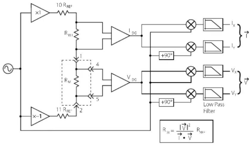
Figure1.1: BlockdiagramoftheSIM921.
1.2Front-PanelOperation
ThefrontpaneloftheSIM921isdividedintoseveralmajorfunctional blocks,eachofwhichwillbediscussed.

Figure1.2:TheSIM921frontpanel.
1.2.1 Resetting to factory defaults
ToresettheSIM921tofactorydefaults,hold[Set]depressedwhile turningpowerontothemodule.Thisisequivalenttotheremote command*RST.
1.2.2Numericdisplay
Theupperblockofthefrontpanelisthenumericdisplayfield. In addition to 5 1/2 digits, six units LEDs (mΩ, Ω, kΩ, MΩ, mK, and K) indicate the physical unit of the quantity displayed. The two buttonstothe left of thenumeric display, [Set ], allow the userto modify settable parameters.
1.2.3Display
Directlybeneath[Set 1]stheDISPLAYblockofthepanel. Thetwo buttonsatthebottomofthissection, [Display ], selectthequantity fordisplayinthenumericfield.
Theselectionsare:
Value: Themeasuredvalueoftheuser'sresistor-under-testisdisplayed, eitherinresistanceunitsortemperatureunits(dependingontheunitsselection,below).
When Valueisdisplayed, pressing[Set]act:basashort-cutto resettheoutputfilter. This can be useful to speed settling with alogtime constant after larger resistance change is made, or after the range excitation is changed.
Value-Offset: This selection (also known as "deviation") also displays the measurementresult(eitherinresistanceortemperatureunits), but after subtracting the user-settable Offset. Pressing [Set 1] willresettheoutputfilter.
Phase (deg.): This selection shows the phase angle between measured currentandvoltage(indegrees), and is an indication of how much capacitive loading is present. Phase is positive for capacitive loads. A phase angle near +90 ° should be viewed with caution: this indicates that most of the current is flowing through there active part of the load, and measurement accuracy may suffer.
Whenphaseisdisplayed,[Set]chbeusedtomodify the modelusedintheSIM921todetermineresistance. Bypassing[Set],thenumericdisplaywillshowtheword: 2E.r o Thisforcesthemetertoassumethephaseanglebetween the voltageandcurrentiszerowhensolvingforR.Thisishelpful whenmeasuringverysmallresistances(suchassuperconductingsamples),sincethephase determination becomesotherwise ill-conditionedwhenthevoltagesignalapproacheszero,and causesexcessnoiseintheresults.Pressing[Set]restoresnormaloperation.
Offset : The offset, or setpoint, is the user-selected value to subtract from the sensor measurement. The offset is used in the Value-Offset display (above), as well as to determine the analogoutputvoltage(seebelow). The[Set ]buttonswill acceleratethroughmultipledigitstoadjusttheoffset;twoshort cutsalsoexist.Ifboth[Set]and[Set]arepressedsimultaneously,Offsetispreloadedwiththelatestmeasurementresult of Value. Depressing both buttons again will force Offset to zero.
Freq. (Hz): This field controls the excitation frequency for the SIM921. [Set ▲]adjuststhefrequencyfrom2Hzto60Hz. Depressing both [Set ▲] and [Set ▼] together will step between 15 Hz, 10 Hz,5Hz,and2.5 Hz.
AOUT :Thisparameteristheslope(inV/ΩorV/K)usedtoscalethe deviationsignalforanalogoutput.Use[Set]toaccelerate throughmanyordersofmagnitudeforA OUT;releasingthe buttonandre-pressingitallowsfinecontroloverthelower digits,asthesettingbeginsacceleratingagain.Ifresistance unitsareselectedforanalogoutput,theΩindicatorwillbelit nexttothenumericdisplay;iftemperatureunitsareselected, theKindicatorwillbelit.
Units (Ω, K): This is actually three separate selections that are stepped throughbycontinuingtopress[Display ].Thefirstselection lights both the Value and Units indicators. This selects either resistance or temperature units for the Value display. Use [Set ▲] to switch between resistance (the display will show r E S.) and temperature (the display will show the ID message oftheselectedsensorcalibrationcurve).
Pressing[Display]againwilllightA OUT and Unit together. Now,[Set]selectsbetweenresistanceortemperatureunits for the analog output function. Note that the deviation display and offset parameter units are also determined by AOUT -Units.
Pressing[Display]onefinaltimewillleaveUnits litalone. Nowthe[Set]selectsamongthreesensorcalibrationcurves stored in the SIM921. If a particular curve has not been loaded, the - islittoindicatethisisnotausablecurve;once(atleast) twopointsareloadedinasensorcurvememory,thedisplay willshow * totheleftofthecurveID.Onlyonecurvecanbe selectedatatime.
1.2.4Range
TheRANGEblockofthefrontpanelselectsthereferenceresistor. Press [Range ▲] to step between ranges from 20 mΩ to 20 MΩ. For all ranges ≥ 2 Ω, the reference resistor RR is1/2thetotalrange. For example, onthe20 kΩrange, RR = 10 kΩ. For ranges ≤ 2 Ω, the RR = 1.0 Ω.
The Autorange subblock controls two independent functions related torange.Brieflytapping[Autorange]willtoggleautorangeDisplay on and off. When Autorange Display is off, the numeric display decimalpointisfixedbasedontheselectedrange.WithAutorange Display on, the decimal point (and possibly the units indicator) shifts todisplaytheresultwithmaximumresolution.
Holding [Autorange] for 2 seconds light Gain and initiate an autogaincycle. Whenever the SIM921 issettoanewrangeorexcitation, the internal amplifiers are preset to nominal gains. This might not be
optimalform measuring resistor that are much smaller than, or larger than, then nominal rangesetting. Also, if the user is in a high-noise environment, out-of-band pick-up might cause amplifiers saturation. In either of these cases, initiating an autogain cycle will force the SIM921 to optimize gains for the signals present at that time. Once completed, the Gain is unlit, and the amplifier gains remain fixed at their new levels. Changing excitation or rangewill reset the amplifier to their (new) nominal settings.
1.2.5Excite
The EXCITEblockcontrol the excitation amplitude for theme measurement. [Excite] step between excitation levels in 1–3–10 steps from 3µV to 30 mV. It is possible to step the amplitudesetting down oncemore from the 3µV setting, setting the excitation amplitude zero. Not that this does not close the hunting relay, as On/Off does (below).
Theamplitude, together with the excitation mode, determines the actual conditions for themeasurement. [Mode], at the bottom of the EXCITEblock, is another dual-function control. Briefly tapping [Mode] toggles the excitation On/Off; when Off, a mechanical relay shunts the excitation current, preventing any current from flowing to the user's resistor.
While the excitation is off, holding [Mode] for 2 secondswill step between four (4) distinct excitation modes:
Constant Current: With Current lit, the SIM921 will operate in constant current mode. This programs an AC current with rms amplitude of excite/ RR ;forexample, if the excitation is set to 100µV and the range is 20kΩ , the excitation current will equal 10nA ( 100µV / 10kΩ = 10nA ). This is implemented by serving the measured voltage across thereferenceresistor, RR to these selected excitation amplitude.
Constant Voltage: With Voltage lit, the SIM921 will operate in constant voltage mode. In this mode, the excitation is served to keep them measured voltage across the user's resistor, RM equal to these selected excitation. This can be particularly useful for negative temperature thermometers at low temperatures, where a constant current would lead to increasing power dissipation at low temperatures ( P=I-2RM, RM, P as T ). With constant voltage, the ohmic dissipation goes down with decreasing temperature ( P=V-2/RM, RM, P as T ).
Constant Power: With both Current and Voltage lit, the SIM921 servoes the excitationtokeepthepowerdissipatedintheuser'sresistor
constant,atthelevel V2 /(RR / 2)
Passive: With neither indicatorlit, the SIM921 disable sex citationserving, and simply sets a fixed AC amplitude acrossthe entire bridge circuit. The amplitude eisset so that for R M upto about the 2RR , the current will approximately equal the corresponding constant-current setting (above). For user resistances much larger than the angesetting ( R M R ), the voltage acrossthe user resistor will approach \~ 20× thenominal excitation (see Figure 1.1).
1.2.6Output
The OUTPUTblockofthefrontpanelselectsthepost-detectionfilter setting, and contains the BNC connector for the analog output. The filter is simple 6dB/octavelow pass filter that calculates a running exponential average of the vector voltages (prior to her at iocalculation). Highersetting of the time constant will reduce measurement noise at the expense of slower settling times. The filter affects the display values as well as the analog output voltages.
[TimeConst.]stepthefiltertimeconstantin1-3-10stepsfrom 0.3s to 300s. Stepping the time constant downwards from 0.3s turns off the 6dB/octave filter completely, leaving only a running boxcar"sync"filter(thataveragesthesignalsovertheoneexcitation period) active. The sync filter effectively eliminates the 2 × f signals fromthedemodulatoroutput,butotherwiseprovideslittlenoise reduction. Thisisanappropriatesettingforrelativelyhighsignal-to-noisemeasurementswheresignalbandwidththisimportant.
ItcantakesixorseventimeconstantsfortheoutputoftheSIM921 tofullysettleafterastepchange;forslowtimeconstantsettings,this can be a bothersome delay. The filter can be reset by pressing [Set Ⅱ] when the display is Value or Value-Offset.
1.2.7 Autocal
The AUTOCAL block controls the internal autocalibration of the SIM921Autocalibrationcross-calibratestherelativegainofthetwo amplifierchainsinthesystem. Theprocesstakesaboutthree(3) minutestocomplete,andcanbestartedbyholding[Autocal]for \~2seconds.Acountdownisdisplayedtoindicateapproximatetime remaining.Theautocalibrationcanbeabortedbypressing[Autocal] againbeforethecyclecompletes—thiswillabandonthecalibration inprogress,andreverttothepreviouscalibrationvalues.
1.3 SensorInterface
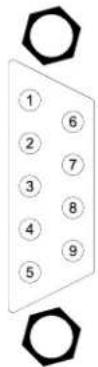
ThesensorinterfaceontheSIM921consistsarear-panelDB-9/Fconnector, labeled "INPUT"(seeFigure1.3). Thepinassignmentsfor thisconnectoraregiveninTable1.1.
| PinSignal |
| 1I+(currentlead) |
| 2I-(currentlead) |
| 3ground |
| 4V+(voltagelead) |
| 5V-(voltagelead) |
| 6ground |
| 7ground |
| 8ground |
| 9ground |
Table1.1:SIM921SensorInterfaceConnectorPins,DB-9.Drawing showspinnumberslookingintotherearoftheinstrument.
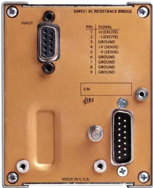
Figure1.3:TheSIM921rearpanel.
1.3.1 Four-wiremeasurement
Toavoidsensitivitytowiringleadresistance,theSIM921isconfiguredforfour-wiremeasurements.Thebasiccircuitforthiswiring schemeisshowninFigure1.4.

Figure1.4: Wiringdiagramforfour-wirereadout.
1.3.2 Two-wiremeasurement
Ifapplication-specificiconstraintslimitthenumberofleadstothe sensor,theSIM921canbewiredtomeasurethesensorresistance withasimpletwo-wirecircuit,showninFigure1.5.Notethatthe leadresistance(pastthejunctionpointsofthecurrentandvoltage leads)willaddasadirectresistanceerrorwhenmeasuringthesensor.

Figure1.5: Wiringdiagramfortwo-wirereadout.
1.3.3 Wiringforhighimpedance
When using the SIM921 to measure high impedances (>fewMΩ), cable construction becomes crucial. It is important that the wire lead should equal low-loss dielectric insulation, such as PTFE (Teflon TM). Ordinary PVC-insulated wire is not well suited to this application, as it can suffer from dielectric absorption effects. Regardless of a
veryhighDCinsulationresistance(>100GΩ),smallACdielectric losses,evenatthelowfrequenciesusedbytheSIM921,canappear as (10s\~100s) MΩ of real impedance in parallel with the user load.
1.4SIMInterface
The primary connection to the SIM921 AC Resistance Bridge is the rear-panel DB-15 SIM interface connector. Typically, the SIM921 is mated to a SIM900 Mainframe viathis connection, either through one of the internal mainframeslots, or theremotecable interface.
ItisalsopossibletooperatetheSIM921directly, without using the SIM900Mainframe. Thissectionprovidesdetailsontheinterface.

CAUTION
TheSIM921hasnointernalprotectionagainstreversepolarity,missing supply,orovervoltageonthepowersupplypins.Misapplicationofpower maycausecircuitdamage.SRSrecommendsusingtheSIM921together withtheSIM900Mainframeformostapplications.
1.4.1 SIMinterfaceconnector
The DB-15 SIM interface connector carries all the power and communications lines to the instrument. The connector signals are specified in Table 1.2
| Pin | Signal | DirectionSrc ⇒ Dest | Description |
| 1 | SIGNAL_GND | MF ⇒ SIM | Ground reference for signal |
| 2 | -STATUS | SIM ⇒ MF | Status/service request (GND = asserted, +5 V= idle) |
| 3 | RTS | MF ⇒ SIM | HW handshake (+5 V= talk; GND = stop) |
| 4 | CTS | SIM ⇒ MF | HW handshake (+5 V= talk; GND = stop) |
| 5 | -REF_10MHZ | MF ⇒ SIM | 10 MHz reference (optional connection) |
| 6 | -5 V | MF ⇒ SIM | Power supply (no connection in SIM921) |
| 7 | -15 V | MF ⇒ SIM | Power supply (analog circuitry) |
| 8 | PS_RTN | MF ⇒ SIM | Power supply return |
| 9 | CHASSISGND | Chassis ground | |
| 10 | TXD | MF ⇒ SIM | Async data (start bit = “0”= +5 V; “1” = GND) |
| 11 | RXD | SIM ⇒ MF | Async data (start bit = “0”= +5 V; “1” = GND) |
| 12 | +REF_10MHz | MF ⇒ SIM | 10 MHz reference (optional connection) |
| 13 | +5 V | MF ⇒ SIM | Power supply (digital circuitry) |
| 14 | +15 V | MF ⇒ SIM | Power supply (analog circuitry) |
| 15 | +24 V | MF ⇒ SIM | Power supply (no connection in SIM921) |
Table1.2:SIMInterfaceConnectorPinAssignments,DB-15
1.4.2 Directinterfacing
TheSIM921isintendedforoperationintheSIM900Mainframe, but users may wish to directly interface the module to their own systems withouttheuseofadditionalhardware.
ThematingconnectorneededisastandardDB-15receptacle,suchas Amppart#747909-2(orequivalent).Clean,well-regulatedsupply voltagesof+5,±15VDCmustbeprovided,followingthepin-out specifiedinTable1.2.Groundmustbeprovidedonpins1and8, withchassisgroundonpin9.The-STATUSsignalmaybemonitored onpin2foralow-goingTTL-compatibleoutputindicatingastatus message.
1.4.2.1 Directinterfacecabling
If the user intend stodirectly wire the SIM921 independent of the SIM900 Mainframe, communication is usually possible by directly connecting the appropriate interfacelines from the SIM921 DB-15 plug to the RS-232 serial port of a personal computer. 1 Connect RXD from the SIM921 directly to RD on the PC, TXD directly to TD, and similarly RTS → RTS and CTS → CTS. In other words, anull-modem styleable is not needed.
TointerfacedirectlytotheDB-9male(DTE)RS-232porttypically foundoncontemporarypersonalcomputers,acablemustbemade withafemaleDB-15sockettomatewiththeSIM921,andafemale DB-9sockettomatewiththePC'sserialport.Separateleadsfrom theDB-15needtogotothepowersupply,makingwhatissometimes knowasa"hydra"cable.Thepin-connectionsaregiveninTable1.3.
DB-15/FtoSIM921Name
DB-9/F
10←→ 3 TxD
11←→ 2 RxD
5 ComputerGround
toP/S
7←→ -15VDC
14←→ +15 VDC
13←→ +5 VDC
8,9←→ Ground (P/S return current)
1←→ Signal Ground (separate wire to Ground)
Table1.3:SIM921DirectInterfaceCablePinAssignments
1 Although the serial interfaces on the DB-15 donots satisfy the minimum voltage level so of the RS-232 standard, they are typically compatible with desktop personal computers
1.4.2.2 Serialsettings
The serial port settings at power-on are: 9600 baud, 8-bits, noparity, 1 stop bit, and no flow control (see Section 2.3.1). The serial settings cannot be changed on the SIM921.
2RemoteOperation
ThischapterdescribesoperatingtheSIM921overtheserialinterface.
InThisChapter
2.1IndexofCommands......2-2
2.2AlphabeticListofCommands......2-4
2.3Introduction....2-7
2.3.1 Power-onconfiguration......2-7
2.3.2Buffers....2-7
2.3.3DeviceClear....2-7
2.4Commands....2-8
2.4.1 Commandsyntax....2-8
2.4.2 Notation ......2-9
2.4.3Examples 2-9
2.4.4Excitationcommands .....2-10
2.4.5 Measurement commands .....2-12
2.4.6 Post-detection processing commands .....2-14
2.4.7 Calibrationcurve commands.....2-15
2.4.8 Autoranging commands.....2-17
2.4.9 Autocalibrationcommand .....2-17
2.4.10 Setpointandanalogoutputcommands....2-17
2.4.11 Interface commands....2-18
2.4.12Statuscommands....2-23
2.5StatusModel 2-26
2.5.1StatusByte(SB)....2-27
2.5.2ServiceRequestEnable(SRE) .....2-28
2.5.3 StandardEventStatus(ESR) .....2-28
2.5.4 StandardEventStatusEnable(ESE).....2-29
2.5.5CommunicationErrorStatus(CESR) .....2-29
2.5.6CommunicationErrorStatusEnable(CESE) .2-30
2.5.7OverloadStatus(OVCR)....2-30
2.5.8OverloadStatus(OVSR)......2-31
2.5.9OverloadStatusEnable(OVSE)......2-31
2.1IndexofCommands
symboldefinition
i,jIntegers
f,gFloating-pointvalues
zLiteraltoken
sArbitrarycharactersequence(no", "or";")
(?)Requiredforqueries;illegalforsetcommands
varParameteralwaysrequired
{var} Requiredparameterforsetcommands;illegalforqueries
[var]Optionalparameterforbothsetandqueryforms
Excitation
| FREQ(?){f} | 2-10Frequency |
| RANG(?){i} | 2-10Range |
| EXCI(?) {i} | 2 - 11 Excitation |
| EXON(?) {z} | 2 - 11 Excitation On/Off |
| MODE(?) {z} | 2 - 11 Excitation Mode |
| IEXC? | 2-11QueryExcitationCurrent |
| VEXC? | 2-11QueryExcitationVoltage |
Measurement
| RVAL? [i] | 2 – 12 Resistance Value |
| RDEV?[i] | 2–12ResistanceDeviation |
| TVAL? [i] | 2 – 12 Temperature Value |
| TDEV? [i] | 2 – 13 Temperature Deviation |
| PHAS?[i] | 2–13Phase |
| TPER(?) {i} | 2 – 13 Time Period for Streaming |
| SOUT | 2–13StopStreaming |
| DISP(?) {i} | 2 – 14 Display |
Post-Detection
| FRST | 2-14FilterReset |
| TCON(?) {i} | 2 - 14 Time Constant |
| PHLD(?) {z} | 2 - 15 Phase Hold |
CalCurves
| DTEM(?) {z} | 2-15 Display Temperature |
| ATEM(?) {z} | 2-15 Analog Output Temperature |
| CURV(?) {i} | 2-15 Sensor Calibration Curve |
| CINI(?) i {,z,s} | 2-16 Initialize Sensor Calibration |
| CAPT i,f,g | 2-16 Add Point to Sensor Calibration |
| CAPT? i,j | 2-16 Query Point in Sensor Calibration |
Autorange
AGAI(?){z} 2-17AutorangeGain
ADIS(?){z} 2-17AutorangeDisplay
Autocalibration
ACAL2-17Autocalibration
Setpoint/AnalogOutput
RSET(?){f} 2-17ResistanceSetpoint
TSET(?){f} 2-18TemperatureSetpoint
VOHM(?) {f} 2-18 Analog Output Scale (V/Ω)
VKEL(?) {f} 2-18 Analog Output Scale (V/K)
AMAN(?) {z} 2-18 Analog Output Manual Mode
AOUT(?) {f} 2-18 Analog Output Manual Value
Interface
*RST 2-19Reset
*IDN? 2-20Identify
*TST? 2-20SelfTest
*OPC(?) 2-20OperationComplete
CONS(?) {z} 2-20 Console Mode
LEXE? 2-21ExecutionError
LCME? 2-21CommandError
LBTN? 2-22Button
TOKN(?) {z} 2-22 Token Mode
TERM(?) {z} 2-22 Response Termination
Status
*STB?[i] 2-23StatusByte
*SRE(?) [i,] {j} 2 - 23 Service Request Enable
*CLS 2-23ClearStatus
PSTA(?) {z} 2-23 Pulsed Status Mode
*ESR?[i] 2-24StandardEventStatus
*ESE(?) [i,] {j} 2-24 Standard Event Status Enable
CESR?[i] 2-24CommunicationErrorStatus
CESE(?) [i,]{j} 2-24 Communication Error Status Enable
OVCR?[i] 2-24OverloadCondition
OVSR?[i] 2-24OverloadStatus
OVSE(?) [i,]{j} 2-25 Overload Status Enable
2.2AlphabeticListofCommands
★
*CLS2-23ClearStatus
*ESE(?) [i,] {j} 2-24 Standard Event Status Enable
*ESR?[i]2-24StandardEventStatus
*IDN?2-20Identify
*OPC(?)2-20OperationComplete
*RST2-19Reset
*SRE(?) [i,] {j} 2 - 23 Service Request Enable
*STB?[i]2-23StatusByte
*TST? 2-20SelfTest
A
ACAL 2-17Autocalibration
ADIS(?) {z} 2-17 Autorange Display
AGAI(?) {z} 2-17 Autorange Gain
AMAN(?) {z} 2-18 Analog Output Manual Mode
AOUT(?) {f} 2-18 Analog Output Manual Value
ATEM(?) {z} 2-15 Analog Output Temperature
C
CAPT i,f,g 2-16 Add Point to Sensor Calibration
CAPT? i,j 2-16 Query Point in Sensor Calibration
CESE(?) [i,]{j} 2-24 Communication Error Status Enable
CESR?[i] 2-24CommunicationErrorStatus
CINI(?) i {,z,s} 2-16 Initialize Sensor Calibration
CONS(?) {z} 2-20 Console Mode
CURV(?) {i} 2-15 Sensor Calibration Curve
D
DISP(?) {i} 2-14 Display
DTEM(?) {z} 2-15 Display Temperature
E
EXCI(?) {i} 2-11 Excitation
EXON(?) {z} 2-11 Excitation On/Off
F
FREQ(?) {f} 2-10 Frequency
FRST 2-14FilterReset
|
IEXC?2-11QueryExcitationCurrent
L
LBTN?2-22Button
LCME?2-21CommandError
LEXE?2-21ExecutionError
M
MODE(?){z} 2-11ExcitationMode
0
OVCR?[i]2-24OverloadCondition
OVSE(?) [i,]{j} 2-25 Overload Status Enable
OVSR?[i]2-24OverloadStatus
P
PHAS?[i]2-13Phase
PHLD(?) {z} 2-15 Phase Hold
PSTA(?) {z} 2-23 Pulsed Status Mode
R
RANG(?) {i} 2-10 Range
RDEV?[i]2-12ResistanceDeviation
RSET(?) {f} 2-17 Resistance Setpoint
RVAL? [i] 2 - 12 Resistance Value
S
SOUT 2-13StopStreaming
T
TCON(?) {i} 2-14 Time Constant
TDEV? [i] 2-13 Temperature Deviation
TERM(?) {z} 2-22 Response Termination
TOKN(?) {z} 2-22 Token Mode
TPER(?) {i} 2-13 Time Period for Streaming
TSET(?) {f} 2-18 Temperature Setpoint
TVAL? [i] 2 – 12 Temperature Value
V
VEXC? 2-11QueryExcitationVoltage
VKEL(?) {f} 2-18 Analog Output Scale (V/K)
VOHM(?) {f}
2-18 Analog Output Scale (V/Ω)
2.3 Introduction
RemoteoperationoftheSIM921istroughasimplecommandlanguagedocumentedinthischapter.Bothsetandqueryformsofmost commandsaresupported,allowingtheusercompletecontrolofthe amplifierfromaremotecomputer,eitherthroughtheSIM900MainframeordirectlyviaRS-232(seeSection1.4.2.1).
SeeTable1.2forspecificationoftheDB-15SIMinterfaceconnector.
2.3.1 Power-onconfiguration
Thesettingsfortheremoteinterfaceare9600baudwithnoparity andnoflowcontrol,andlocalechodisabled(CONS0FF).
MostoftheSIM921instrumentsettingsarestoredinnon-volatile memory, andatpower-ontheinstrumentreturnstothestateitwas lastinwhenpowerwasremoved.Exceptionsarenotedinthecommanddescriptions.
Resetvaluesofparametersareshowninboldface.
2.3.2Buffers
Incomingdatafromthehostinterfaceisstoredina64-byteinput buffer. Charactersaccumulateintheinputbufferuntilacommand terminator (either CR or LF ) is received, at which point the messageis parsedandexecuted. QueryresponsesfromtheSIM921are bufferedina64-byteoutputqueue.
If the input buffer overflows, then all data in both the input buffer and the output queue are discarded, and an error is recorded in the CESRandESRstatus registers.
2.3.3DeviceClear
TheSIM921hostinterfacecanbeasynchronouslyresettoitspower-onconfigurationbysendinganRS-232-style(break) signal.Fromthe SIM900Mainframe,thisisaccomplishedwiththeSRSTcommand; ifdirectlyinterfacingviaRS-232,thenuseaserialbreaksignal.After receivingtheDeviceClear,theinterfaceisresetto9600baudand CONS mode is turned 0FF. Note that this only resets the communicationinterface;thebasicfunctionoftheSIM921isleftunchanged; toresettheinstrument,see*RST.
TheDeviceClearsignalwillalsoterminateanystreamingoutputs from the SIM921 due to a TVAL? or RVAL? query of multiple conversions.
2.4Commands
Thissectionprovidessyntaxandoperationaldescriptionsforremote commands.
2.4.1 Commandsyntax
The four letter mnemonic (shown in CAPS) in each command sequence specifies the command. Therest of these sequence consists of parameters.
Commandsmaytakeeithersetorqueryform,dependingonwhether the“?”characterfollowsthemnemonic.Setonlycommandsare listed without the “?”, query only commands show the “?” after the mnemonic,andoptionallyquerycommandsaremarkedwitha“(?)”.
Parametersshownin{ } and[]arenotalwaysrequired.Parametersin{ } arerequiredtosetavalue,andareomittedforqueries.Parametersin[]areoptionalinbothsetandquerycommands.Parameterslisted withoutanysurroundingcharactersarealwaysrequired.
Donotsend()or{ } or[]aspartofthecommand.
Multipleparametersareseparatedbycommas.Multiplecommands maybesentononecommandlinebyseparatingthemwithsemicolons(;)solongastheinputbufferdoesnotoverflow.Commands are terminated by either CR or LF characters. Null commands andwhitespaceareignored. Executionofcommand(s)doesnot beginuntilthecommandterminatorisreceived.
tokens Token parameters (generically shown as z in the command descriptions) can be specified either as a keyword or integer value. Command descriptions list the valid keyword options, with each keyword followed by its corresponding integer value. Forexample, to set the response termination sequence to CR + LF , the following two commands are equivalent:
TERM CRLF —or— TERM 3
Forqueriesthatreturntokenvalues,thereturnformat(keywordor integer)isspecifiedwiththeTOKNcommand.
2.4.2 Notation
The following tables summarize the notation used in the command descriptions:
SymbolDefinition
i,jIntegers
f,gFloating-pointvalues
zLiteraltoken
sArbitrarycharactersequence(no", "or";")
(?)Requiredforqueries;illegalforsetcommands
varParameteralwaysrequired
{var} Requiredparameterforsetcommands;illegalforqueries
[var]Optionalparameterforbothsetandqueryforms
2.4.3Examples
Each command is provided with as simple example illustrating its usage. In these examples, all data sent by the host computer to the SIM921 are set as straight teletype font, while responses received the host computer from the SIM921 are set as slanted teletype font.
Theusageexamplesvarywithrespecttoset/query,optionalparameters,andtokenformats. Theseexamplesarenotexhaustive,butare intended to provide a convenient starting point for user programming.
2.4.4 Excitation commands
FrequencyFREQ(?){f}
Set (query) the excitation frequency {to f Hz}.
Theexcitationfrequencycanbesetwithapproximately10mHzresolution. The parameter f must be in the range 1.95 ≤ f ≤ 61.1 . The resetvalueis10.0.
Inthefollowing, theexcitationissetto13.7Hz. Example:
FREQ13.7;FREQ?
13.7025
RangeRANG(?){i}
Set(query)theresistancerange{toi}.
Validrangecodesare:
| i | Range |
| 0 | 20mΩ |
| 1 | 200mΩ |
| 2 | 2Ω |
| 3 | 20Ω |
| 4 | 200Ω |
| 5 | 2kΩ |
| 6 | 20kΩ |
| 7 | 200kΩ |
| 8 | 2MΩ |
| 9 | 20MΩ |
Example: RANG5
| ExcitationEXCI(?){i} | |
| Set(query)thenominalexcitation{toi}. | |
| Validexcitationcodesare: | |
| i|Excitation | |
| -10(excitationoff) | |
| 03μV | |
| 110μV | |
| 230μV | |
| 3100μV | |
| 4300μV | |
| 51mV | |
| 63mV | |
| 710mV | |
| 830mV | |
| EXCI?Example: | |
| 3 | |
| EXON(?) {z} | Excitation On/Off |
| Set (query) the excitation source {to z=(OFF 0, ON 1)}. | |
| EXON1Example: | |
| ExcitationModeMODE(?){z} | |
| Set (query) the excitation mode {to z=(PASSIVE 0, CURRENT 1, VOLTAGE 2, POWER 3)}. | |
| Example: TOKNON; MODE?PASSIVE | |
| IEXC? | QueryExcitationCurrent |
| Querytheactualexcitationcurrentamplitude,inamperes. | |
| IEXC?Example:+1.043700E-07 | |
| VEXC? | QueryExcitationVoltage |
| Query the actual excitation voltage amplitude, in volts. This is the voltage measured across the sensor itself, not the “nominal” excita-tionacrosstheentirebridge(setbyEXCI). | |
| VEXC?Example:+1.176760E-05 |
2.4.5 Measurement commands
| ResistanceValueRVAL?[i]Querythemeasuredvalueofresistance,inohms.Iftheoptional/isspecified,then/measurementresultsarereturned to the host, separated by TPER milliseconds. If i=0 is specified, then streamingofRVAL?resultscontinuesindefinitelyuntiltheSOUT commanddisreceived.RVAL?4Example:+1.130924E+02+1.131047E+02+1.130922E+02+1.130764E+02 | |
| ResistanceDeviationRDEV?[i]Querythemeasuredvalueofresistance,inohms,offsetbytheresistancesetpoint(seeRSET).Iftheoptional/isspecified,then/measurementresultsarereturned to the host, separated by TPER milliseconds. If the optional i is specified,then/measurementresultsarereturnedtothehost,separated by TPER milliseconds. If i=0 is specified, then streaming results continuesindefinitelyuntiltheSOUTcommanddisreceived. | |
| Example: | RSET100RDEV?+1.308144E+01 |
| TVAL?[i] | TemperatureValueQuerythemeasuredvalueoftemperature,inkelvin.Iftheoptional/isspecified,then/measurementresultsarereturned to the host, separated by TPER milliseconds. If the optional i is specified,then/measurementresultsarereturnedtothehost,separated by TPER milliseconds. If i=0 is specified, then streaming results continuesindefinitelyuntiltheSOUTcommanddisreceived. |
| Example: | TVAL?+3.067459E+02TemperatureDeviationTDEV?[i]Querythemeasuredvalueoftemperature,inkelvin, offsetby the temperaturesetpoint(seeTSET).Iftheoptionalisspecified, thenimeasurementresultsarereturned to the host, separated by TPER milliseconds. If the optional i is spec- ified, thenimeasurementresultsarereturnedtothehost,separated by TPER milliseconds. If i=0 is specified, then streaming results continuesindefinitelyuntiltheSOUTcommandisreceived. |
| Example: | TSET 306TDEV?+7.345581E-01 |
| PHAS?[i] | PhaseQuerythephaseofthemeasuredvoltage(indegrees)withrespect totheexcitationcurrent. Positiveanglescorrespondtocapacitive loads.ThisquerydisregardsthePHLDsetting.Iftheoptionalisspecified, thenimeasurementresultsarereturned to the host, separated by TPER milliseconds. If the optional i is spec- ified, thenimeasurementresultsarereturnedtothehost,separated by TPER milliseconds. If i=0 is specified, then streaming results continuesindefinitelyuntiltheSOUTcommandisreceived. |
| Example: | PHAS?+0.022 |
| TPER(?) {i} | Time Period for StreamingSet (query) the time period {to i}, in ms. TPER can be set with 10 ms resolution in the range 100 ≤ i ≤ 6555350. The reset value is 1000. |
| Example: | TPER 500 |
| SOUT | StopStreamingTurnoffstreamingoutput.StreamingisalsohaltedbytheDeviceClearsignal(serialbreak),but notby*RST. |
| Example: | TDEV?0+8.273926E-01+8.048706E-01SOUT |
DisplayDISP(?) i
Set(query)thedisplayselection{toi}.
Validdisplaycodesare:
iDisplay
Units
1Units+A OUT
2 Units+ Value
3A OUT
4Freq.(Hz)
5Offset
6Phase(deg.)
7 Value-Offset
8Value
DISPVALUEExample:
2.4.6 Post-detection processing commands
| FilterResetFRSTResetthepost-detectionfilter.FRSTExample: | |
| TCON(?) {i} | Time ConstantSet (query) the time constant for the post-detection filter { to i }.Validtimeconstantcodesare:iTimeConstant-1filteroff(synconly)00.3 s11 s23 s310 s430 s5100 s6300 s |
| Example: | TCON2 |
| PhaseHoldPHLD(?){z} |
| Set (query) the phase hold mode {to z=(OFF 0, ON 1)}. |
| Forcestheresistancecalculationtoassumezerophase.Thismode isusefulformemeasurementsofverylowresistance(suchassuper-conductingtransitions)wheretherawsignal-to-noiseratiobecomes muchlessthanunity. |
| PHLDONExample: |
2.4.7 Calibrationcurve commands
| DisplayTemperatureDTEM(?){z} | |
| Set (query) the display temperature mode {to z=(OFF 0, ON 1)}. | |
| When ON, the SIM921 display for Value will be in temperature units insteadofresistance. | |
| Example: | DTEM? |
| ON | |
| ATEM(?) {z} | Analog Output Temperature |
| Set (query) the analog output temperature mode {to z=(OFF 0, ON 1)}. | |
| WhenON,theSIM921generatesananalogoutputproportional to temperaturedeviationinsteadofresistancedeviation.Also,thedis-play units for Value-Offset and Offset are set with ATEM. | |
| Example: | ATEM? |
| 1 | |
| CURV(?) {i} | Sensor Calibration Curve |
| Set (query) the selected sensor calibration curve {to i}. Valid curve numbers are 1, 2, and 3. A curve number may be selected with CURV evenifnocorrespondingcurvehasbeenloadedintotheSIM921. | |
| Example: | CURV? |
| 2 | |
| CINI(?) i {,z,s} | Initialize Sensor CalibrationInitialize sensor calibration curve i=(1, 2, or 3).Thesetformofthecommand,CINIIi,z,s,erasestheoldcontentsof curve i. The second parameter z=(LINEAR 0, SEMILOGT 1, SEMILOGR 2,LOGLOG3)definesthesensorcurveformat.ThethirdparameterSisanarbitraryidentificationstringforthissensorcalibration curve.Thisstringcanconsistofanynon-blankcharactersexcept thecomma“,”orsemicolon“;”,andcanbeupto15charactersin length.Theleading5characterswillbedisplayedontheSIM921 frontpanelwhenthecurveisselected,withinthelimitationsofthe seven-segmentdisplayhardware. |
| Example: | CINI3, SEMILOGR,GRT75 _Thequeryformofthecommand,CINI?i,returnsthefollowingresponse: <format>,<serial>,nwhere <format> is the calibration curve format (same as z above),<serial> is the full identification string for the curve, and n is the numberofpointscurrentlystoredinthecurve. |
| Example: | CINI?2LINEAR,PT100,225 |
| CAPTi,f,g | AddPointtoSensorCalibrationAdd a new point to sensor calibration curve i. f is the raw sensor value(ineitherohmsorlog 10(ohms),dependingoncurveformat), and g is the corresponding temperature value (in either kelvin or log10(kelvin),againdependingoncurveformat).Notethatcurvepointsmustbeaddedinincreasingorderofsensor valuef. |
| Example: | CAPT 3, 3.223631, 127.542E-3 In the preceding, a point is added for R = 1.67352 kΩ, T = 127.542 mK. The curve format is SEMILOGR, sotherawsensorvaluetransmittedislog 10(1.67352 × 10³) |
| CAPT?i,j | QueryPointinSensorCalibrationQuerythevalueofsensorcalibrationcurvei,entrypointj.Theresponse is<sensor>,<temperature>,where <sensor> is the raw sensor value (in either ohms or log10(ohms), depending on curve format), and <temperature> is the corresponding temperature value (in either kelvin or log10(kelvin), again depending oncurveformat). |
CAPT?3,45Example:
3.223631E+00,1.275420E-01
2.4.8 Autoranging commands
| AutorangeGainAGAI(?){z} | |
| Set (query) autoranging of gain {to z=(OFF 0, ON 1)}. When autoranginggain,theSIM921willoptimizesignal-to-noiseforthecurrentandvoltagemeasurementchannels.Afterautoranginggain completes, the SIM921 automatically turns AGAI OFF. Nominal gains are restored by sending the RANG or EXCI commands, with either thepriorsettingoranewsetting. | |
| Note that if AGAI is commanded off with a remote command prior to the completion of the autoranging cycle, the internal gains will be left in an indeterminate state. To restore proper operation, either re-issue the AGAI ON command, or send a new RANG or EXCI command. | |
| Example: | AGAION |
| ADIS(?) {z} | Autorange Display |
| Set (query) autoranging of the display {to z=(OFF 0, ON 1)}. The ADIS setting has no effect on the SIM921 measurement, and only modifiesthefront-paneldatapresentation. | |
| Example: | ADISON |
2.4.9 Autocalibration command
| ACAL | AutocalibrationInitiate the internal autocalibration cycle (takes approximately 3 minutes). Remotecommandswillnotbeprocessedfurtheruntilthe autocalibrationiscompleted. |
| Example: ACAL |
2.4.10 Setpointandanalogoutputcommands
| RSET(?) {f} | Resistance Setpoint |
| Set (query) the resistance setpoint {to f ohms}. This is the “offset” or “setpoint” valueusing generating the analog output when ATEM OFF. The reset value is 1.0. | |
| Example: | RSET? |
| +1.000000E+02 | |
| TemperatureSetpointTSET(?){f} | |
| Set (query) the temperature setpoint {to f kelvin}. This is the “offset” or “setpoint” value used generating the analog output when ATEMON.Theresetvalueis1.0. | |
| TSET?Example: +3.060000E+02 | |
| VOHM(?) {f} | Analog Output Scale (V/Ω) |
| Set (query) the analog output scale { to f V/Ω}. This is the scale used when ATEM OFF. The reset value is 1.0. | |
| VOHM1E-3Example: | |
| VKEL(?) {f} | Analog Output Scale (V/K) |
| Set (query) the analog output scale { to f V/K}. This is the scale used when ATEM ON. The reset value is 1.0. | |
| VKEL?Example: 1.000000E+00 | |
| AMAN(?) {z} | Analog Output Manual Mode |
| Set (query) the analog output manual mode {to z=(OFF 0, ON 1)}. When ON, the analog output is simply equal to the AOUT value; whenOFF,theoutputisthescaledandoffsetmeasurementresult. | |
| Example: | AMANON |
| AOUT(?) {f} | Analog Output Manual Value |
| Set (query) the Analog Output Manual value {to f volts}. This is the output value when AMAN ON. The initial value after power-on is 0.0, butthisvalueisnotmodifiedby*RST. | |
| Example: | AOUT-1.234 |
2.4.11 Interfacecommands
Reset*RST
ResettheSIM921todefaultconfiguration.*RSTexecutesthefollowingcommands:
- FREQ10
• RANG6 - EXCI1
- EXONON
- MODEPASSIVE
- TPER1000
- DISP0
- TCON1
- PHLDOFF
• DTEMOFF - ATEMOFF
- ADISON
- RSET1.0
- TSET1.0
VOHM1.0 - VKEL1.0
- AMANOFF
- TOKNOFF
Commands or settings which are not altered by *RST are: SOUT, CURV, AOUT, CONS, TERM, PSTA, and all service-enable registers (*SRE, *ESE, CESE, OVSE).
*RSTExample:
| Identify*IDN?Readthedeviceidentificationstring.Theidentificationstringisformattedas:StanfordResearchSystems, SIM921, s/n******, ver#.#where*****isthe6-digitserialnumber,and#.#isthefirmware revisionlevel.*IDN?Example:StanfordResearchSystems, SIM921, s/n003075, ver3.6 | |
| SelfTest*TST?Thereisnoself-testfunction.*TSTwillalwaysreturn0.*TST?Example:0 | |
| OperationComplete*OPC(?)OperationComplete.SetstheOPCflagintheESRregister.Thequeryform*OPC?writesa1intheoutputqueuewhencomplete, butdoesnotaffecttheESRregister.*OPCExample: | |
| ConsoleModeCONS(?){z}Set (query) the console mode {to z=(OFF 0, ON 1)}.CONScauseseachcharacterreceivedattheinputbuffertobecopied totheoutputqueue.Atpower-onandDevice-Clear,CONSissettoOFF.CONS?Example:0 |
ExecutionErrorLEXE?
Querythelastexecutionerrorcode.AqueryofLEXE?alwaysclears theerrorcode,soasubsequentLEXE?willreturn0. Validcodesare:
ValueDefinition
0NoexecutionerrorsincelastLEXE?
1Illegalvalue
2Wrongtoken
3Invalidbit
16Uninitializedcurve
17Curvefull
18Curvepointout-of-order
19Curvepointpastend
*STB?12;LEXE?;LEXE?Example:3
0 The error (3, "Invalid bit," ) is because *STB? only allows bit-specific queries of 0-7. ThesecondreadofLEXE? returns 0.
CommandErrorLCME?
Querythelastcommanderrorcode.AqueryofLCME?alwaysclears theerrorcode,soasubsequentLCME?willreturn0. Validcodesare:
ValueDefinition
0NoexecutionerrorsincelastLCME?
1Illegalcommand
2Undefinedcommand
3Illegalquery
4Illegalset
5Missingparameter(s)
6Extraparameter(s)
7Nullparameter(s)
8Parameterbufferoverflow
9Badfloating-point
10Badinteger
11Badintegertoken
12Badtokenvalue
13Badhexblock
14Unknowntoken
*IDNExample:
LCME?
4Theerror(4,"Illegalset")isduetothemissing"?".
ButtonLBTN? Querythelastbutton-presscode.AqueryofLBTN?alwaysclears thebuttoncode,soasubsequentLBTN?willreturn0. Validcodes are:
ValueDefinition
0nobuttonpressedsincelastLBTN?
1[Display] ▼
2[Display] ▲
3[Set] ▼
4[Set] ▲
5undef
6[Excite] ▼
7[Excite] ▲
8[Range] ▼
9[Range] ▲
10[Autocal]
11[Autorange]
12[Mode]
13[TimeConst.] ▼
14[TimeConst.] ▲
LBTN?Example: 12
TokenModeTOKN(?) {z} Set (query) the Token Query mode {to z=(OFF 0, ON 1)}. If TOKN ON is set, then queries to the SIM921 that return tokens will returnthetextkeyword; otherwise they returnthedecimalinteger value. Aninterestingillustration of this is the observation that the only possible responses to the TOKN? query are ON and 0. At power-on, TOKNissettoOFF.
Example: TOKNOFF
TERM(?) {z}
Response Termination
Set (query) the term sequence {to z=(NONE\ 0, CR\ 1, LF\ 2, CRLF\ 3, LFCR\ 4) }. The term sequence is appended to all query responses sent by the module, and is constructed of ASCII character(s) 13 (carriage return) and 10 (line feed). The token mnemonic gives the sequenceofcharacters.
Atpower-on, TERMissettoCRLF.
TERM?Example: 3
2.4.12Statuscommands
| TheStatuscommandsqueryandconfigureregistersassociatedwith statusreportingoftheSIM921. | |
| StatusByte*STB?[i]ReadstheStatusByteregister[biti].The*STB?querycausesthe-STATUSsignaltobereleasedifasserted.(SeealsoPSTA)*STB?Example:16 | |
| *SRE(?) [i,] {j} | Service Request EnableSet (query) the Service Request Enable register [bit i] {to j}.Notethatbit1oftheSREimplementsalocal(front-panel)keypadfirmwarerelease4.0 lockout function. Setting bit 1 (*SRE 1,1) disables the keypad. Clear-ingbit1(*SRE 1,0)re-enablesthefrontpanel. |
| Example: | *SRE 0,1 |
| *CLS | ClearStatus*CLSimmediatelyclearstheESR,CESR,andOVSR. |
| Example: | *CLS |
| PSTA(?) {z} | Pulsed Status ModeSet (query) the Pulse -STATUS Mode {to z=(OFF 0,ON 1)}.When PSTA ON is set, any new service request will only pulse the -STATUS signal low (for a minimum of 1 μs). The default behavior istolatch-STATUSlowuntila*STB?queryisreceived.Onreset,PSTAassettoOFF.PSTA?Example:OFFStandardEventStatus*ESR?[i]ReadstheStandardEventStatusRegister[biti].Uponexecuting*ESR?,thereturnedbit(s)oftheESRregisterare cleared.*ESR?Example:64 |
| *ESE(?) [i,]{j} | Standard Event Status EnableSet (query) the Standard Event Status Enable Register [bit i] {to j}.*ESE6, 1Example:ESE?64 |
| CommunicationErrorStatusCESR?[i]QueryCommunicationErrorStatusRegister[forbiti].UponexecutingaCESR?query,thereturnedbit(s)oftheCESR registerarecleared.CESR?Example:0 | |
| CESE(?) [i},{j} | Communication Error Status EnableSet (query) Communication Error Status Enable Register [for bit i] {toj}CESE?Example:0 |
| OVCR?[i] | OverloadConditionQueryOverloadConditionRegister[forbiti].0VCR?Example:0 |
| OVSR?[i] | OverloadStatusQueryOverloadStatusRegister[forbiti].UponexecutingaOVSR?query,thereturnedbit(s)oftheOVSR registerarecleared.0VSR?Example:0 |
OVSE(?) [i,]j
Overload Status Enable
Set (query) Overload Status Enable Register [for bit i] {to j}
0VSE3Example:
2.5StatusModel
TheSIM921statusregistersfollowthehierarchicalIEEE-488.2format.AblockdiagramofthestatusregisterarrayisgiveninFigure2.1.
TherearethreecategoriesofregistersintheSIM921statusmodel:
ConditionRegisters: Theseread-only registers correspond to thereal-time condition of some underlying physical property being monitored. Queries return the latest value of the property, and haveno othereffect. Condition regist names end with CR.
EventRegisters: Theseread-only registers record the occurrence of defined events. Whentheevent occurs, the corresponding bit is set to 1. Upon querying an event register, any set bits within it are cleared. These are sometimes known as "sticky bits," since once set, a bit can only be cleared by reading its value. Event register names end with SR.
Enable Registers : These read/write registers define a bitwise mask for their corresponding event register. If any bit position is set in an event registerwhilethesamebitpositionisalsosetinthecenable register,thenthecorrespondingsummarybitmessageisset. Enableregister namesendwithSE.
![graph TD A["Standard Event Status"] --> B["ESR ESE"] A --> C["Overload Status"] C --> D["OGVCR OVSR OVSE"] A --> E["Status Byte"] E --> F["-STATUS"] subgraph Standard Event Status G["PON: Power On 7, URQ: User Request 6, CME: Command Error 5, EXE: Execution Error 4, DDE: Device Error 3, QYE: Query E…](/content/2026/05/931254/images/646bcad9bf074fa2eba5915a5ea002995bbae393eaef6ce8455614e30c6da04e.jpg)
Figure2.1:StatusRegisterModel for theSIM921AC Resistance Bridge.
2.5.1StatusByte(SB)
TheStatusByteisthetop-levelsummaryoftheSIM921statusmodel. WhenmaskedbytheServiceRequestEnableregister,abitsetintheStatusBytecausesthe-STATUSsignaltobeassertedontherear-panelSIMinterfaceconnector.
Typically, -STATUSremainsasserted(low)untila*STB?queryis received, atwhichtime-STATUSisdeasserted(raised) 1 . Afterclearingthe-STATUSsignal, itwillonlybere-assertedinresponseoa newstatus-generatingcondition.
| WeightBitFlag | |
| 10 | OVSB |
| 21 | undef(0) |
| 42 | undef(0) |
| 83 | undef(0) |
| 164 | IDLE |
| 325 | ESB |
| 646 | MSS |
| 1287 | CESB |
OVSB:OverloadStatusSummaryBit.Indicateswhetheroneormore oftheenabledflagsintheOverloadStatusRegisterhasbecome true.
IDLE: Indicates that the input buffer is empty and the command parserisidle. CanbeusedtohelpsynchronizeSIM921query responses.
ESB:EventStatusBit.Indicateswhetheroneormoreoftheenabled eventsintheStandardEventStatusRegisteristrue.
MSS:MasterSummaryStatus. Indicateswhetheroneormoreof theenabledstatusmessagesintheStatusByteregisteristrue. Notethatwhile-STATUSisreleasedbythe*STB?query,MSS isonlyclearedwhentheunderlyingenabledbitmessage(s)are cleared.
CESB:CommunicationErrorSummaryBit.Indicateswhetheroneor moreoftheenabledflagsintheCommunicationErrorStatus Registerhasbecometrue.
Bits in the Status Byte are not cleared by the *STB? query. These bits are only cleared by reading the underlying event registers, or by clearing the corresponding enableregisters.
2.5.2ServiceRequestEnable(SRE)
EachbitintheSREcorrespondsone-to-onewithabitintheSB register, and acts as a bitwise AND of the SB flag to generate the MSSbitintheSB and the -STATUS signal.
| WeightBitFlag |
| 10OVSBEnable |
| 21KEYLOCK |
| 42undef(0) |
| 83undef(0) |
| 164IDLEEnable |
| 325ESBEnable |
| 646undef(0) |
| 1287CESBEnable |
Bit6oftheSREisundefined—settingithasnoeffect,andreadingit alwaysreturns0.Thisregisterissetandqueriedwiththe*SRE(?) command.
Bit1oftheSRE(binaryweight2)isaspecialfunction, "KEYLOCK", firmwarerelease4.0 and is unrelated to the SIM921 status system. Setting this bit resultsintheSIM921ignoringallfrontpanelkeypresses, essentially implementingalocallockoutfunction.
Thisregisterisclearedatpower-on.
2.5.3 StandardEventStatus(ESR)
TheStandardEventStatusregisterconsistsof8eventflags. These event flags are all "sticky bits" that are set by the corresponding event, andclearedonlybyreadingorwiththe*CLScommand.Readinga single bit (with the *ESR? i query) clears only bit i.
| WeightBitFlag | |
| 10 | OPC |
| 21 | INP |
| 42 | QYE |
| 83 | DDE |
| 164 | EXE |
| 325 | CME |
| 646 | URQ |
| 1287 | PON |
OPC: OperationComplete.Setbythe*OPCcommand.
INP : Input buffer Error. Indicates data has been discarded from the inputbuffer.
QYE: QueryError. Indicates data in the output queue has been lost.
DDE: DeviceDependentError. Undefined for SIM921.
EXE:ExecutionError.Indicatesanerrorinacommandthatwas successfully parsed. Out-of-rangeparametersareanexample. The error code can be queried with LEXE?.
CME:CommandError.Indicatesaparser-detectederror.Theerror codecanbequeredwithLCME?.
URQ:UserRequest.Indicatesafront-panelbuttonwaspressed.
PON:PowerOn.Indicatesthatanoff-to-ontransitionhasoccurred.
2.5.4 StandardEventStatusEnable(ESE)
TheESEactsasabitwiseANDwiththeESRregistertoproducethe singlebitESBmessageintheStatusByteRegister(SB).Itcanbeset andqueriedwiththe*ESE(?)command.
Thisregisterisclearedatpower-on.
2.5.5 CommunicationErrorStatus(CESR)
TheCommunicationErrorStatusregisterconsistsof8eventflags; eachofwhichissetbythecorrespondingevent,andclearedonlyby readingorwiththe*CLScommand.Readingasinglebit(withthe CESR?iquery)clearsonlybiti.
| WeightBitFlag | |
| 1 | 0PARITY |
| 2 | 1FRAME |
| 4 | 2NOISE |
| 8 | 3HWOVRN |
| 16 | 4OVR |
| 32 | 5RTSH |
| 64 | 6CTSH |
| 128 | 7DCAS |
PARITY:ParityError. Setbyserialparitymismatchonincomingdata byte.
FRAME : Framing Error. Set when an incoming serial data byte is missing the STOPbit.
NOISE:NoiseError. Setwhenanincomingserialdatabytedoesnot presentasteadylogiclevel during eachasynchronousbit-periodwindow.
HWOVRN:HardwareOverrun.Setwhenanincomingserialdatabyteis lostduetointernalprocessorlatency. Causestheinputbuffer tobeflushed,andresetsthecommandparser.
OVR:InputbufferOverrun.Setwhentheinputbufferisoverrun byincomingdata.Causestheinputbuffertobeflushed,and resetsthecommandparser.
RTSH:UndefinedfortheSIM921.CommandError.Indicatesaparser-detectederror.
CTSH:UndefinedfortheSIM921.
DCAS:DeviceClear.Indicates the SIM921 received the Device Clear signal (an RS-232
2.5.6 CommunicationErrorStatusEnable(CESE)
TheCESEactsasabitwiseANDwiththeCESRregistertoproduce thesinglebitCESBmessageintheStatusByteRegister(SB).Itcan besetandqueriedwiththeCESE(?)command.
Thisregisterisclearedatpower-on.
2.5.7 OverloadStatus(OVCR)
TheOverloadConditionRegisterconsistsof7single-bitmonitorsof conditioneventswithintheSIM921.BitsintheOVCRreflectthe real-timevaluesoftheircorrespondingsignals. Readingtheentire register,orindividualbitswithinit,doesnotaffecttheOVCR.
| Weight | Bit | Flag |
| 1 | 0 | ANALOG |
| 2 | 1 | PREAMP |
| 4 | 2 | CURRENT |
| 8 | 3 | UNDERSP |
| 16 | 4 | OVERSP |
| 32 | 5 | UNDERT |
| 64 | 6 | OVERT |
| 128 | 7 | undef(0) |
ANALOG: Analogoverload. Asignalamplifierwassaturated.
PREAMP: Thefront-endpreampsaturated.
CURRENT:Theexcitationcurrentexceeded12mA(saturation).
UNDERSP:Theexcitationservofellbelow90%ofthecommandedexcitation.
OVERSP:Theexcitationservoexceeded110%ofthecommandedexcitation.
UNDERT: Calibrationcurveunderflow(R<R min).
OVERT: Calibrationcurveoverflow(R>R min).
2.5.8 OverloadStatus(OVSR)
TheOverloadStatusRegisterconsistsof(latching)eventflagsthat correspondone-to-onewiththebitsoftheOVCR(seeabove).Upon thetransition0→ 1ofanybitwithintheOVCR,thecorresponding bitintheOVSRbecomesset.
BitsintheOVSRareunaffectedbythe1→ 0transitionsintheOVCR, andareclearedonlybyreadingorwiththe*CLScommand.Reading a single bit (with the OVSR? i query) clears only bit i.
Anadditionalbit,AUTOGAINDONE(weight=128,bit=7)isdefinedintheOVSRtosignalcompletionofanautorangegaincycle.
2.5.9 Overload Status Enable (OVSE)
TheOVSEactsasabitwiseANDwiththeOVSRregistertoproduce thesinglebitOVSBmessageintheStatusByteRegister(SB).Itcan besetandqueriedwiththeOVSE(?)command.
Thisregisterisclearedatpower-on.
3PartsListsandSchematics
ThischapterpresentsabriefdescriptionoftheSIM921circuitdesign. Acompletepartslistandcircuitschematicsareincluded.
InThisChapter
3.1 CircuitDiscussion....3-2
3.1.1 Digitalboard....3-2
3.1.2 Front-panelboard....3-3
3.1.3 Sourceboard....3-3
3.1.4AmplifierBoard....3-4
3.2PartsLists ....3-6
3.2.1 DigitalandFrontPanelBoards .....3-6
3.2.2SourceBoard....3-7
3.2.3AmplifierBoard....3-8
3.3SchematicDiagrams ......3-8
3.1 CircuitDiscussion
TheSIM921isassembledfrom4interconnectedprintedcircuit boards:threefull-sizedboardsrunningthelengthofthemodule, andonefront-paneldisplayboard.Inthischapter,pagereferences aretothe9-sheetschematicspagesattheendofthemanual.
3.1.1 Digitalboard
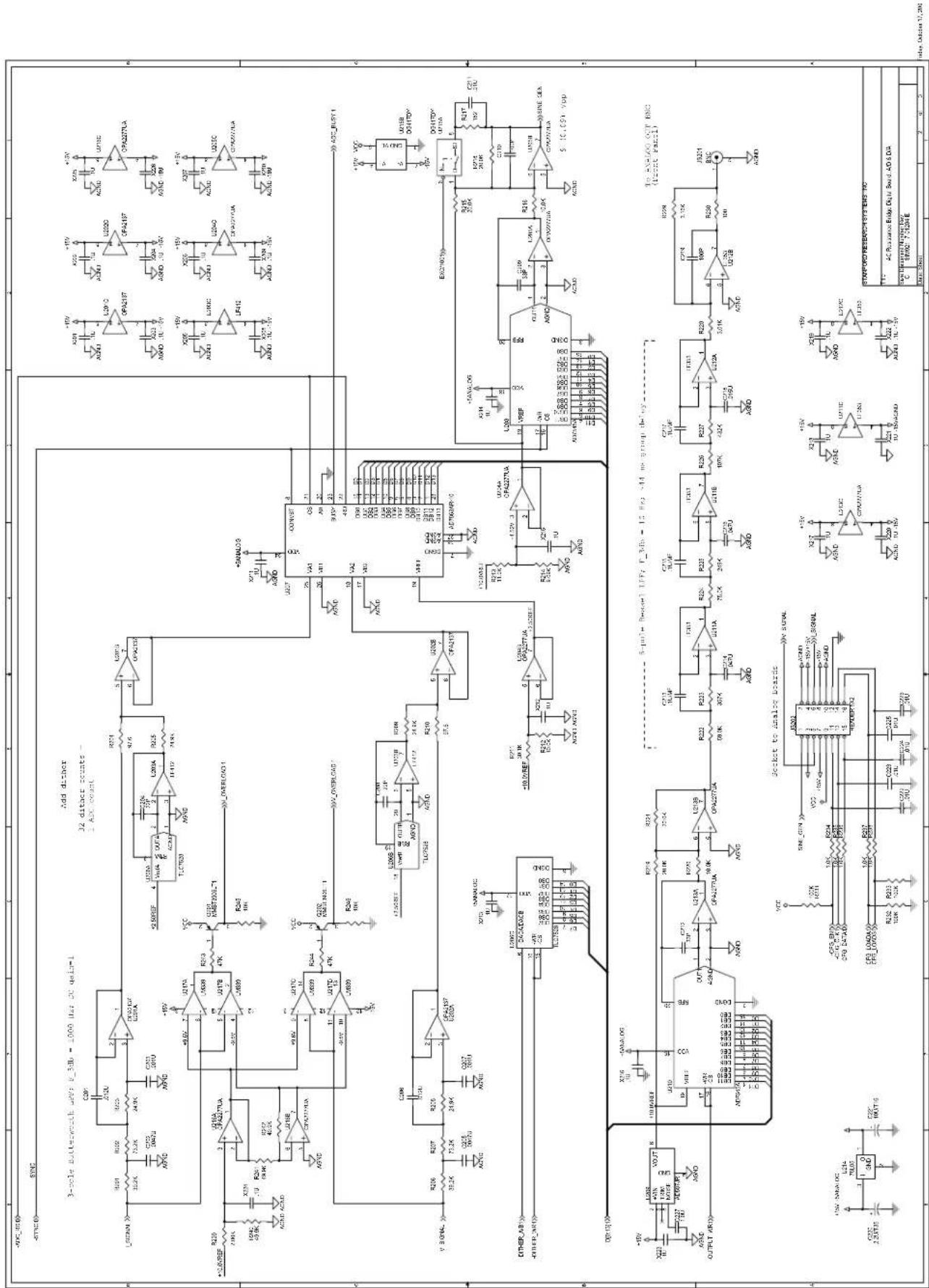
Thedigitalboard(pages1,2,&3)containsthemicrocontrollerchip, digitalI/O,andtheanalog-to-digitalanddigital-to-analogconverters.Beawarethatthefourmountingscrewssecuringthisboard tothechassisare"locked"bythethreadedstand-offsholdingthe sourceboard.Beforeattemptingtoremovethesescrews,theamplifierboard,sourceboard,andthreadedstand-offsmustberemoved,orthescrewswilllikelystriporbreak.
3.1.1.1 ClockandMCU
AllfunctionsoftheSIM921arecoordinatedbythemicrocontroller, U103,whichoperatesin"single-chip" mode (internalRAMand ROM).Extendednon-volatilememoryisprovidedbyU105forstorageofuseralibrationcurves. Theclockcircuit(Y101,U102,and relatedcomponents)isamodifiedPierceoscillator. Inthepresence ofanexternal10 MHzreferenceclockfromtheSIM900Mainframe, the oscillator will lock to the reference (over a several hundred Hertz window)through thecouplingofR108.Ifnoexternal10 MHzreferenceispresent, thentheoscillatorsimplyfree-runs.
3.1.1.2 Sinegenerator
The excitation sine-wave is created with a 4kHz direct digital synthesis. DAC U208 is updated with new values every 250 µs ; these values are calculated from asinetable within interpolation, scaled for excitation amplitude. Forsmallamplitudes, U215 canswitchina divide-by-100 feedback network. Theresultissent to the analog source board via JS202.
3.1.1.3I and V Analog-to-Digitalconverter
The main signals from the amplifier board, I_SIGNAL and V_SIGNAL, are received at JS202 (which interconnects with both analog boards). ThesignalsareNyquistfilteredwith3-poleButterworthlow-pass filters(U201A&U202A),andthensummedwithaDAC-generated dithersignal(U206)toincreasetheeffectiveresolutionandlinearity
of the ADC. Themainconverter, U207, isa14-bitsimultaneously-sampling two-channel analog-to-digital converter, readout data samplerate of \~4kHz.
3.1.1.4 Analogoutput
Thefront-panelanalogoutputisgeneratedatU210,a12-bitdigital-to-analogconverter.ThisDACisupdatedat\~4kHzwiththesum oftheslowly-varyingoutputsignalandahigh-freqencyrandom dither.The6-pole,10HzoutputBessellow-passfilter(U211&U212) completelyblocksthedithercomponent,providinga16-bitoutput resolution.
3.1.2 Front-panelboard
Thefront-panelboard(page3)containsthedrivecicuitryforthe displaycomponentsoftheSIM921.NotethatallLEDsaredriven staticallyfromU307-U318.
Thereadoutforthebuttonswitchesissomewhatsubtle.Initially,the BUTTONSENSElinesarealldrivenlow,andtheBUTTONPRESS lines are diode-or'd together (D103, D104, page 1) to detect any button closure. Once a button closure is detected, the the BUTTONSENSElinesarechangedintoinputs,andtheBUTTONPRESS linesaredrivenhigh, one-by-one, todecodewhichbutton(s)are pressed.
3.1.3 Sourceboard
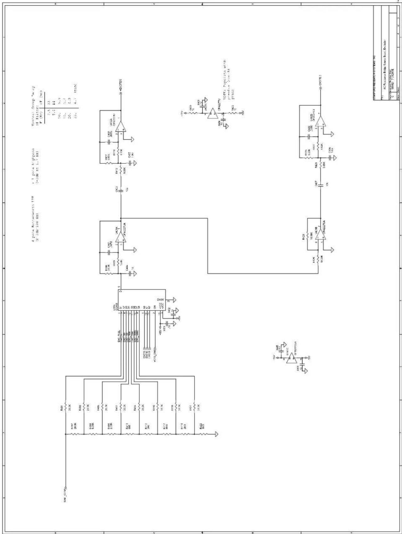
The analog source board (pages 4,5, & 6) receives the SINEGEN output from the sine-wave generator, filters it, and switches in the appropriate half-bridgeset of resistors for these selected range.
The attenuator selector (U403) is only switched between the top three settings (EXC_FULL, EXC_/3, EXC_/10); greater attenuations areswitchedinwithU215,orbyreducingthenumericamplitudeofthesinetablevalues.Afterattenuating,thesignalisfilteredandsplit into complementary polarities, ±EXCITE. The first two poles of the low-pass filter are implemented by U401A, while the last two poles areimplementedseparatelyforthetwopolaritiesbyU402A&B.In themiddleofthisfilter,theinvertedpolarityisgeneratedbyU401B,andtheDC-offsetofbothpolaritiesisblockedbyC403&C407.Noticethataftertheblockingcapacitors,alow-offset(non-A)grade opampmustbeusedforU402.
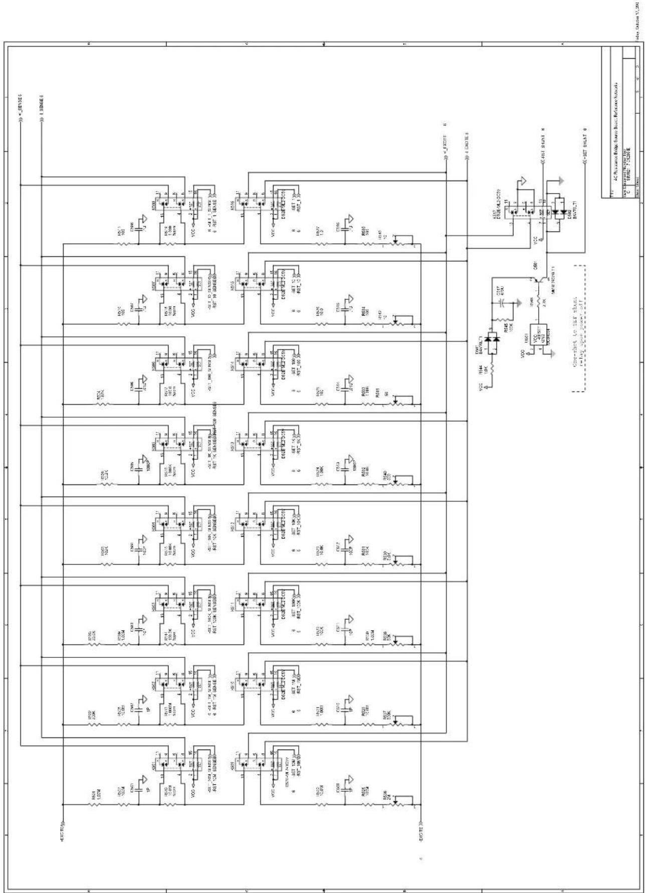
3.1.3.2 Referenceresistorbridges
Eachrangefrom1Ωto100MΩhasitsownhalf-bridgenetwork (page5),alldrivenby±EXCITE.Theselectedrangeisswitchedto the±IEXCITEleadstotheuser's(external)resistorthroughone ofrelaysK509–K516,whilethecorresponding(internal)reference resistorR512–R519isswitchedonto±ISENSEwithoneofK501–K508. Thetrim-pots(R536–R543)areallaccessiblethroughthetop ventilationslots,andfactory-adjustedtobalancethetopandbottom legsofthehalf-bridges.
RelayK517shortsthe±IEXCITElinestoeachotherandground. Thisrelayisclosedwhenevertheexcitationiscommandedoff,and alsouponpower-offbytheone-shotcircuitaroundU501.
Noticethat±IEXCITEisconnectedtotheamplifierboardbyJP603 neartheupper-rearcorneroftheboard,while±ISENSEisconnected totheamplifierboardbyJP602nearthelower-frontcornerofthe board.Thesesignalsareroutedasfarfromeachotheraspossibleto minimizecross-talk.
3.1.3.3 Interconnect
Themainconnectionforpower, control, and high-level analog signals is JP601. Notethatthisisa "tall" header, with pinsextending through both sides of the source board. This connectermates with JS202 on the digital board, and also with JS901 on the amplifier board.
3.1.4AmplifierBoard
All the circuitry on the preamp board (pages 7, 8, & 9) is duplicated identically, as much as possible, for the two signal paths, V and I .
3.1.4.1 Preamplifiers
Thetwosignals±V _SENSEcomefromtheKelvin(voltage-sense) leadsacrossstheuser'sexternalresistorundermeasurement,while the±ISENSEsignalsarethesenseleadsfromtheinternalreference resistor(page5). Undernormaloperation,relaysK701&K702are in the reset position, connecting the ±V SENSE to the V-channel preamp (Q702 and associated circuitry), and connecting ±I SENSE to the I-channelpreamp(Q701andassociated).Thepreampsarefixed gain(10×),high-impedance DC-coupledvoltageamplifiersusingthe LSK389dualJFETforinputs.
During an autocalibration cycle, the two relays K701, K702 are both switched to the set position, tying both preampstothe ± ISENSE internal signal (K517 is also switched closed, providing a complete
internalcurrentpath, and disconnecting all circuitry from the external resistor). Sincethe fundamental measurement of the SIM921 is ratiometric, this cross-calibration of the two amplifier channels sufficient to remove gain-dependent systematic errors in the resistance measurement.
3.1.4.2 Programmablegainamplifier
Page8showsthetwo(identical)channelsofprogrammablegain amplifier.Eachamplifierisconstructedoftwostagesofvariable gain(upto+50dB),connectedbyavariableattenuatorandAC-couplingstage.The-3dBpointfortheAC-couplingis\~1.6Hz. Notethatthefactorycalibrationincludesamodelforeachofthese AC-couplingfilters,sotofirstordertheautocalibrationcycleshould notbenecessarywhenchangingexcitationfrequencies.
3.1.4.3RFfiltering
The4signalsthatconnecttotheexternalresistorundermeasurement (±I_EXCITEand±VSENSE)eachpassthroughanL-R-Cπ-filter locatedrightbehindtheexternalDB-9connector(JS904).
3.2PartsLists
Thepartslistsareseparatedbytheinternal(SRS)assemblykit,which consistofoneortwoboardseach.
3.2.1 DigitalandFrontPanelBoards
Reference SRS P/N Part Value Reference SRS P/N Part Value
| C101 5-00345 4.0-34P R206,R201 4-01270 | 39.2K | ||||||
| C102 5-00366 18P | R207,R202 4-01296 | 73.2K | |||||
| C103 | 5-00376 | 120P | R203,R205,R208,R209 | 4-01251 | 24.9K | ||
| C104 5-00368 27P | R210,R204 4-01020 | 97.6 | |||||
| C105,C106,C107 | 5-00102 | 4.7U | R211 | 4-01259 | 30.1K | ||
| C108,C109,C110 | 5-00387 | 1000P | R212,R216,R220 | 4-01213 | 10.0K | ||
| C206,C201 5-00455 .012U | R213 4-01217 | 11.0K | |||||
| C202,C205 5-00450 .0047U | R214 4-01209 | 9.09K | |||||
| C203,C207 | 5-00442 | .001U | R215,R218,R219,R221 | 4-01242 | 20.0K | ||
| C204,C208 5-00367 22P | R217 4-01046 | 182 | |||||
| C212,C209 5-00369 33P | R222 4-01287 | 59.0K | |||||
| C210,C219 5-00375 100P | R223 4-01362 | 357K | |||||
| C211 5-00454 .01U | R224 4-01297 | 75.0K | |||||
| C213,C215,C217 | 5-00466 | .1U/MF | R225 | 4-01347 | 249K | ||
| C216,C214 5-00462 .047U | R226 4-01312 | 107K | |||||
| C218 5-00456 .015U | R227 4-01370 | 432K | |||||
| C220 5-00318 2.2U/T35 | R228 4-01163 | 3.01K | |||||
| C221 5-00471 10U/T16 | R229 4-01165 | 3.16K | |||||
| C222,C223,C224,C225,C226 | 5-00298 | .01U | R230 | 4-01021 | 100 | ||
| C227 5-00542 1.0U | R239 4-01146 | 2.00K | |||||
| D101,D102 | 3-00945 | BAT54S | R240,R241,R242 | 4-01280 | 49.9K | ||
| D103,D104 3-00649 BAW56LT1 | R243,R244 4-01519 | 47K | |||||
| D301,D302,D303,D304,D305, | 3-00424 | GREEN | R301 | 4-01489 | 2.7K | ||
| D306,D307,D308,D309,D310, | S301,S302,S303,S304,S305, | 2-00053 | B3F-1052 | ||||
| D311,D312,D313,D314,D315, | S306,S307,S308,S309,S310, | ||||||
| D316,D317,D318,D319,D320, | S311,S312,S313 | ||||||
| D321,D322,D323,D324,D326, | U101 3-00903 MAX6348 | ||||||
| D327,D328,D329,D330,D331, | U102 3-01378 74HCU04 | ||||||
| D332,D333,D334,D335,D336, | U103 3-01379 68HC912B32 | ||||||
| D337,D338,D339,D340,D341, | U104 3-00662 74HC14 | ||||||
| D342,D343,D344 | U105 3-01390 25LC640 | ||||||
| D325 3-00426 YELLOW | U106 3-00902 | 74HC00 | |||||
| JP101 | 1-00302 | 6 PIN DIF CES | U202,U201 | 3-01385 | OPA2137 | ||
| JP103 | 1-00367 | 15 PIN D | U203 | 3-00726 | LF412 | ||
| JP301 | 1-00219 | TMS-115-01-G-S | U204,U205,U213 | 3-01373 | OPA2277UA | ||
| JS201 | 1-00003 BNC | U206 3-01391 TLC7528 | |||||
| JS202 | 1-00104 | HEADER 8X2 | U207 | 3-01392 | AD7863AR-10 | ||
| JS301 | 1-00351 | SMS-115-01-G-S | U210,U208 | 3-01393 | AD7545A | ||
| L101,L102,L103 | 6-00174 | BEAD U209 3-00542 | AD587JR | ||||
| Q201,Q202 | 3-00580 | MMBT3906LT1 | U211,U212 | 3-00724 | LF353 | ||
| RN301,RN302,RN303,RN304, | 4-00407 | 2.7K | U214 | 3-00116 | 78L05 | ||
| RN305,RN306,RN307,RN308, | U215 3-01371 DG417DY | ||||||
| RN309,RN310,RN311 | U216 3-00952 OPA2277UA | ||||||
| RN312,RN313,RN314,RN315, | 4-00442 | 1.2K | U217 | 3-00727 | LM339 | ||
| RN316,RN317,RN318,RN319, | U301 3-01424 HDSP-A107 | ||||||
| RN320,RN321,RN322,RN323 | U302,U303,U304,U305,U306 | 3-00290 | HDSP-A101 | ||||
| R101 | 4-01495 | 4.7K | U307,U308,U309,U310,U311, | 3-00672 | 74HC595ADT | ||
| R102 4-01511 22K | U312,U313,U314,U315,U316, | ||||||
| R103 4-01431 10 | U317,U318 | ||||||
| R104,R106,R113,R118,R245, | 4-01503 | 10K | X101,X102,X103,X104,X105, | 5-00299 | .1U | ||
| R246 | X106,X107,X108,X109,X110, | ||||||
| R105,R107,R234,R235,R236, | 4-01479 1.0K | X111,X112,X201,X202,X203, | |||||
| R237,R238 | X204,X205,X206,X207,X208, | ||||||
| R108 4-01057 237 | X209,X210,X211,X212,X213, | ||||||
| R109 4-01405 1.00M X214,X215,X216,X217,X218, | |||||||
| R110,R115,R117,R121 | 4-01455 100 | X219,X220,X221,X222,X223, | |||||
| R111,R112,R119,R231,R232, | 4-01527 100K | X224,X225,X226,X301,X302, | |||||
| R233 | X303,X304,X305,X306,X307, | ||||||
| R114,R116,R120 | 4-01465 270 | X308,X309,X310,X311,X312 | |||||
| R122 4-01510 20K | Y101 | 6-00571 10.000MHz | |||||
3.2.2 SourceBoard
Reference SRS P/N Part Value Reference SRS P/N Part Value
| C401 5-00462 .047U R502 4-01338 200K | ||
| C402,C406 5-00464 .068U R504 4-01118 1.02K | ||
| C403,C407 5-00072 10U R505 4-01310 102K | ||
| C404 5-00466 .1U R506 4-01214 10.2K | ||
| C405,C408 5-00245 1.0U R507,R528 4-00306 100M | ||
| C501,C502,C509,C510 5-00313 1P R508,R520,R529 4-00139 10.0M | ||
| C511,C503 5-00363 10P | R510,R511 4-01023 105 | |
| C512,C504 5-00375 100P | R512 4-01654 10.0M | |
| C505,C513 5-00387 1000P | R513 4-01652 1.000M | |
| C506,C514 5-00411 .01U R514 4-01651 100.0K | ||
| C507,C508,C515,C516 5-00411 .1U R515 4-01650 10.00K | ||
| C517 5-00260 470U | R516 4-01649 1.000K | |
| D501,D502 3-00544 BAV70LT1 | R517 4-01648 100.0 | |
| JP601 | 1-00406 16 PIN DIL (long) | R518 4-01647 10.00 |
| JP602,JP603 | 1-00488 2 PIN | R519 4-01646 1.000 |
| K501,K502,K503,K504,K505, | 3-00308 DS2E-ML2-DC5V | R521 4-00131 1.00M |
| K506,K507,K508,K509,K510, | R522 4-00142 100K | |
| K511,K512,K513,K514,K515, | R523 4-00138 10.0K | |
| K516,K517 | R524 4-00130 1.00K | |
| Q501,Q601,Q602,Q603,Q604, | 3-00927 MMBT2907ALT1 | R525 4-00141 100 |
| Q605,Q606,Q607,Q608,Q609, | R526 4-00234 10.0 | |
| Q610,Q611,Q612,Q613,Q614, | R527 4-00800 1.0 | |
| Q615,Q616,Q617,Q618,Q619, | R531 4-01309 100K | |
| Q620,Q621,Q622,Q623,Q624, | R532 4-01213 10.0K | |
| Q625,Q626,Q627,Q628,Q629, | R533 4-01117 1.00K | |
| Q630,Q631,Q632,Q633,Q634 | R535,R534 4-01021 100 | |
| R401,R406,R414,R416,R418, | 4-01261 31.6K | R536 4-00250 2M |
| R421 | R537 4-00624 500K | |
| R402,R503 4-01242 20.0K | R538 4-00232 50K | |
| R403 4-01251 24.9K | R539 4-00240 5.0K | |
| R404 4-01198 6.98K | R540 4-00253 500 | |
| R405 4-01257 28.7K | R541 4-00342 50 | |
| R407,R412,R425,R428 4-01209 9.09K | R542,R543 4-00349 10 | |
| R408 4-01146 2.00K | R544 4-01479 1.0K | |
| R409 4-01232 15.8K | R545 4-01527 100K | |
| R410,R427 4-01180 4.53K | R546,R601 4-01489 2.7K | |
| R411 4-01260 30.9K | U401 3-01471 OPA2227UA | |
| R413 4-01102 698 | U402 3-00670 OPA2277U | |
| R415 4-01050 200 | U403 3-01386 DG408 | |
| R417 4-01006 69.8 | U501 3-00671 MC34064 | |
| R419 4-00954 20.0 | U601 3-00662 74HC14 | |
| R420,R423 4-01431 10 | U602,U603,U604,U605,U606 | 3-00787 74HC595 |
| R422 4-00925 10.0 | X401,X402,X403,X404,X405, | 5-00299 .1U |
| R426,R424 4-00218 10.00K | X406,X601,X602,X603,X604, | |
| R501,R509,R530 4-01405 1.00M | X605,X606 | |
3.2.3AmplifierBoard
Reference SRS P/N Part Value Reference SRS P/N Part Value
C701,C704,C711,C716,C719,5-001002.2U R853
C721,C723,C724,C727,C733,R723,R757 4-00983 40.2
C738,C742,C743,C746,C810,R724,R725,R758,R759 4-01648 100
C811,C813,C815,C816,C817,R760,R727 4-00487 20
C827,C828,C830,C832,C833,R730,R763 4-01280 49.9K
C834 R731,R767 4-01164 3.09K
C707,C713,C730,C736 5-00098 10U
C710,C734 5-00363 10P
C801,C802,C818,C819 5-00372 56P
C803,C804,C820,C821 5-00382 390P
C805,C806,C822,C823 5-00450 .0047U
C807,C808,C824,C825,C901,5-00375 100P
C902,C903,C904,C905,C906,R808,R809,R835,R836 4-01145 1.96K
C907,C908
C809,C826 5-00244 .1U
C812,C814,C829,C831 5-00367 22P
D702,D705 3-00674 MMBZ5228 R843,R816 4-01064 280
JS901 1-00104 SOCKET 8x2
JS903,JS902 1-00115 SOCKET 1x2
JS904
K701,K702
L901,L902,L903,L904
Q701,Q702 3-01674 LSK389B
Q901.Q902.Q903.Q904
R701,R735 4-01042 165
R702,R706,R736,R740 4-01021 100
R737,R703 4-00013 50K
R704,R705,R738,R739 4-00528 499
R707,R708,R709,R710,R741,4-01309 100K
R742,R744,R745
R711,R733,R743,R766 4-01060 255
R714,R715,R750,R751 4-01649 1.000K
R716,R752 4-00954 20
R718,R728,R748,R762 4-01141 1.78K
R719,R756 4-00971 30.1
R720,R734,R749,R765,R817,4-01431 10
R818,R820,R823,R825,R826,X808,X809,X810,X811,X812,
R844,R845,R847,R850,R852,X901,X902,X903,X904
R732,R768 4-01213 10.0K
R801,R802,R828,R829 4-01386 634K
R803,R804,R830,R831 4-01338 200K
R805,R806,R810,R812,R832,4-01242 20.0K
R833,R837,R839
R834.R807 4-01088 499
1145 1.96K
R838.R811 4-01076 374
R813,R814,R840,R841 4-01146 2.00K
R815,R842 4-01405 1.00M
|
2 R846,R819 4-01052 210
2 R848,R821 4-01040 158
R849,R822 4-01028 118
0C5V R824,R851 4-01016 88.7
D R854,R827 4-01062 267
R901,R902,R903,R904 4-00992 49.9
07ALT1 U701,U710
U702,U711 3-00998 OPA227UA
U703,U712 3-00096 LM317L
U718,U709 3-00100 LM337L
U801,U802,U807,U808 3-01369 DG409
U803,U809 3-01386 DG408DY
U804,U810 3-00133 OPA131
U805,U806,U811,U812 3-00731 5534
U901 3-00662 74HC14
U902,U903,U904 3-00787 74HC595
X701,X702,X706,X707,X709, 5-00299 .1U
X710,X714,X715,X801,X802,
X803,X804,X805,X806,X807,
3.3 SchematicDiagrams
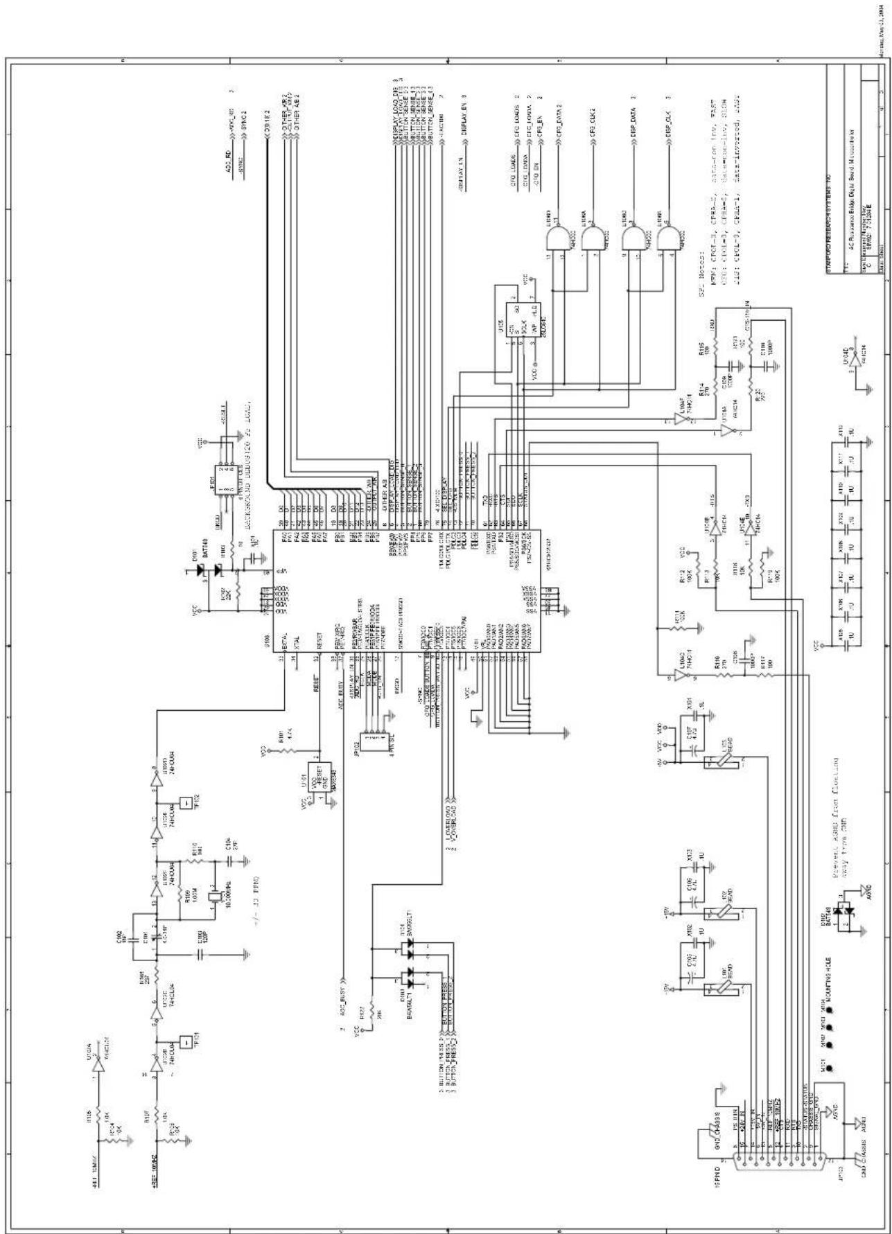
Schematicdiagramsfollowthispage.









- CERTIFICATION
- WARRANTY
- SERVICE
- CONTENTS
- GENERALINFORMATIONIII
- 1GETTINGSTARTED1-1
- 2REMOTEOPERATION
- 3CIRCUITRY
- GENERALINFORMATION
- NOTATION
- SPECIFICATIONS
- RESOLUTION
- GENERAL CHARACTERISTICS
- 1GETTINGSTARTED
- INTHISCHAPTER
- 1.1 INTRODUCTION TO THE INSTRUMENT......1-2
- 1.2FRONT-PANELOPERATION....1-3
- 1.3SENSORINTERFACE....1-8
- 1.4SIMINTERFACE 1-11
- 1.1 INTRODUCTION TO THE INSTRUMENT
- 1.1.1 OVERVIEW
- 1.2FRONT-PANELOPERATION
- 1.2.1 RESETTING TO FACTORY DEFAULTS
- 1.2.2NUMERICDISPLAY
- 1.2.3DISPLAY
- THESELECTIONSARE
- 1.2.4RANGE
- 1.2.5EXCITE
- 1.2.6OUTPUT
- 1.2.7 AUTOCAL
- 1.3 SENSORINTERFACE
- 1.3.1 FOUR-WIREMEASUREMENT
- 1.3.2 TWO-WIREMEASUREMENT
- 1.3.3 WIRINGFORHIGHIMPEDANCE
- 1.4SIMINTERFACE
- CAUTION
- 1.4.1 SIMINTERFACECONNECTOR
- 1.4.2 DIRECTINTERFACING
- 1.4.2.1 DIRECTINTERFACECABLING
- 1.4.2.2 SERIALSETTINGS
- 2.1INDEXOFCOMMANDS
- AUTORANGE
- AUTOCALIBRATION
- SETPOINT/ANALOGOUTPUT
- INTERFACE
- STATUS
- 2.2ALPHABETICLISTOFCOMMANDS
- ★
- A
- C
- D
- E
- F
- L
- M
- 0
- P
- R
- S
- T
- V
- 2.3 INTRODUCTION
- 2.3.1 POWER-ONCONFIGURATION
- 2.3.2BUFFERS
- 2.3.3DEVICECLEAR
- 2.4COMMANDS
- 2.4.1 COMMANDSYNTAX
- 2.4.2 NOTATION
- 2.4.3EXAMPLES
- 2.4.4 EXCITATION COMMANDS
- 2.4.5 MEASUREMENT COMMANDS
- 2.4.6 POST-DETECTION PROCESSING COMMANDS
- 2.4.11 INTERFACECOMMANDS
- RESET*RST
- EXECUTIONERRORLEXE
- VALUEDEFINITION
- COMMANDERRORLCME
- 2.5STATUSMODEL
- 2.5.1STATUSBYTE(SB)
- 2.5.2SERVICEREQUESTENABLE(SRE)
- 2.5.3 STANDARDEVENTSTATUS(ESR)
- 2.5.4 STANDARDEVENTSTATUSENABLE(ESE)
- 2.5.5 COMMUNICATIONERRORSTATUS(CESR)
- 2.5.6 COMMUNICATIONERRORSTATUSENABLE(CESE)
- 2.5.7 OVERLOADSTATUS(OVCR)
- 2.5.8 OVERLOADSTATUS(OVSR)
- 2.5.9 OVERLOAD STATUS ENABLE (OVSE)
- 3PARTSLISTSANDSCHEMATICS
- 3.1 CIRCUITDISCUSSION....3-2
- 3.2PARTSLISTS ....3-6
- 3.3SCHEMATICDIAGRAMS ......3-8
- 3.1 CIRCUITDISCUSSION
- 3.1.1 DIGITALBOARD
- 3.1.1.1 CLOCKANDMCU
- 3.1.1.2 SINEGENERATOR
- 3.1.1.3I AND V ANALOG-TO-DIGITALCONVERTER
- 3.1.1.4 ANALOGOUTPUT
- 3.1.2 FRONT-PANELBOARD
- 3.1.3 SOURCEBOARD
- 3.1.3.2 REFERENCERESISTORBRIDGES
- 3.1.3.3 INTERCONNECT
- 3.1.4AMPLIFIERBOARD
- 3.1.4.1 PREAMPLIFIERS
- 3.1.4.2 PROGRAMMABLEGAINAMPLIFIER
- 3.1.4.3RFFILTERING
- 3.2PARTSLISTS
- 3.2.1 DIGITALANDFRONTPANELBOARDS
- 3.2.2 SOURCEBOARD
- 3.2.3AMPLIFIERBOARD
- 3.3 SCHEMATICDIAGRAMS
Brand : SRS
Model : SIM921
Category : Electrical measuring device