
Strider ST85F-PT - Mobile Device Charger SILVERSTONE - Free user manual and instructions
Find the device manual for free Strider ST85F-PT SILVERSTONE in PDF.


| Product Type | ATX Power Supply |
| Model | Strider ST85F-PT |
| Brand | SilverStone |
| Max. DC Output | 850W |
| Efficiency Certification | 80 PLUS Platinum |
| Form Factor | PS/2 (ATX) |
| Dimensions (W x H x D) | 150 mm x 86 mm x 140 mm |
| Weight | Approx. 2.5 kg |
| Input Voltage | 100-240 VAC (90-264 VAC) |
| Input Frequency | 50-60 Hz (47-63 Hz) |
| Max. Input Current | 12A |
| +3.3V Output | 22A, ±3% regulation, 50 mV ripple |
| +5V Output | 22A, ±3% regulation, 50 mV ripple |
| +12V Output | 70.9A, ±3% regulation, 120 mV ripple |
| -12V Output | 0.3A, ±10% regulation, 120 mV ripple |
| +5VSB Output | 3.0A, ±5% regulation, 50 mV ripple |
| Combined +3.3V & +5V | 120W max |
| Combined +12V | 850W max |
| Fan Size | 120 mm |
| Fan Control | Semi-fanless operation (intelligent) |
| Modular Cabling | 100% modular |
| RAIL Design | Single +12V rail |
| Protections | OVP, UVP, OCP, OPP, SCP, OTP |
| MTBF | 100,000 hours |
| Operating Temperature | 0°C to 40°C |
| Safety Certifications | cTUVus, CB, TUV |
| EMI Compliance | CE, FCC |
Frequently Asked Questions - Strider ST85F-PT SILVERSTONE
User questions about Strider ST85F-PT SILVERSTONE
0 question about this device. Answer the ones you know or ask your own.
Ask a new question about this device
Download the instructions for your Mobile Device Charger in PDF format for free! Find your manual Strider ST85F-PT - SILVERSTONE and take your electronic device back in hand. On this page are published all the documents necessary for the use of your device. Strider ST85F-PT by SILVERSTONE.
USER MANUAL Strider ST85F-PT SILVERSTONE
STRIDER PLATINUM SERIES ST85F-PT
World's smallest 80 PLUS Platinum, full-modular ATX power supplies
High efficiency with 80 PLUS Platinum certification
Compact design with a depth of 140mm for easy integration
100% modular cables
24/7 continuous power output with 40°C operating temperature
Class-leading single +12V rail
Strict ±3% voltage regulation and low ripple & noise
Ultra silent 120mm fan with intelligent semi-fanless operation
SPECIFICATION
SilverStone Strider Platinum
SST-ST85F-PT
ATX12V / EPS 12V Switching Power Supply
With Active PFC
80Plus Platinum
PS/2
1. General
1.1 Scope
This specification defines the performance characteristics of a single phase 750, 650, 550 watts, 5 output power supply. This specification also defines worldwide safety and electromagnetic compatibility requirements for the power supply which is intended for use in computer products.
2. Input Characteristics
2.1 Input Voltage
Nominal Voltage
100-240 Vrms
Voltage Variation Range
90 - 264 Vrms
2.2 Input Frequency
Nominal Frequency
50-60 Hz
Frequency Variation Range
47 Hz to 63 Hz
2.3 Max. Input AC Current
Max. Input Current
12A
Measuring Range
90 - 264 Vrms
2.4 Inrush Current
The power supply must meet inrush requirements for any rated AC voltage, during turn on at any phase of AC voltage, during a single cycle AC dropout condition, during repetitive ON/OFF cycling of AC, and over the specified temperature range. The peak inrush current shall be less than the ratings of its critical components (including input fuse, bulk rectifiers, and surge limiting device).
2.5 Efficiency
ST85F-PT provides an efficiency of 90% minimum when measured at 20% load, provides an efficiency of 92% minimum when measured at 50% load, provides an efficiency of 89% minimum when measured at 100% load, under 115V/60Hz and 230V/50Hz condition.
3. Output characteristics
3.1 Normal Operation Output
| Output Voltage | Load MIN | Range MAX | Regulation | Ripple & Noise P-P Max. |
| 1. +5V | 0.2A | 22A | ±3% | 50mV |
| 2. +12V | 0.0A | 70.9A | ±3% | 120mV |
| 3. -12V | 0.0A | 0.3A | ±10% | 120mV |
| 4. +5Vs | 0.0A | 3.0A | ±5% | 50mV |
| 5. +3.3V | 0.0A | 22.0A | ±3% | 50mV |
■ Maximum continuous total DC output power should not exceed 850W.
■ Maximum continuous combined load on +3.3VDC and +5VDC outputs shall not exceed 120W.
■ Maximum combined load on +12V outputs shall not exceed 850W.
NOTE:
Noise test should be measured with 20 MHz bandwidth frequency oscilloscope. The output terminal shall add a tantalum capacitor of 10uF in parallel with a ceramic capacitor of 0.1uF.
3.2 Remote On/Off Controlled mode
The PSON# signal is required to remotely turn on/off the power supply, PSON# is an active low signal that turns on the output power rails. When this is not pulled low by the system, or left open, the outputs (except the +5VSB) turn off. This signal is pulled to a standby voltage by a pull-up resistor internal to the power supply.
TTL level "H" 2.0 V - 5.25 V
"L" 0.0 V - 1.0 V
3.3 Regulation
The cross regulation defined as follows, the output regulation should be within the specified range.
| Load | +5V | +3.3V | +12V | -12V | +5Vsb |
| Light Load. | 2.49A | 2.49A | 12.18A | 0.05A | 0.52A |
| Typical Load | 6.22A | 6.22A | 30.45A | 0.13A | 1.29A |
| Full Load | 12.43A | 12.43A | 60.90A | 0.26A | 2.58A |
3.4 Rise Time
DC output rise time is less than 20 mS at nominal line and full load.
3.5 Hold-up Time
DC +5V, +3.3V, 12V output maintains at least 16mS after power off which hold within 70% loads under 230V/50Hz condition.
3.6 5VSB
5VSB is required for the implementation of PS-ON described above. 5VSB is a standby voltage that may be used to power circuits that require power input during the powered-down state of all power rails. The 5 VSB pin should deliver 5V ± 5% at a minimum of 3.0 A for PC board circuits to operate. Conversely, PC board should draw no more than 3.0A maximum form this pin. This power may be used to operate circuits such as soft power control.
3.7 PG-OK
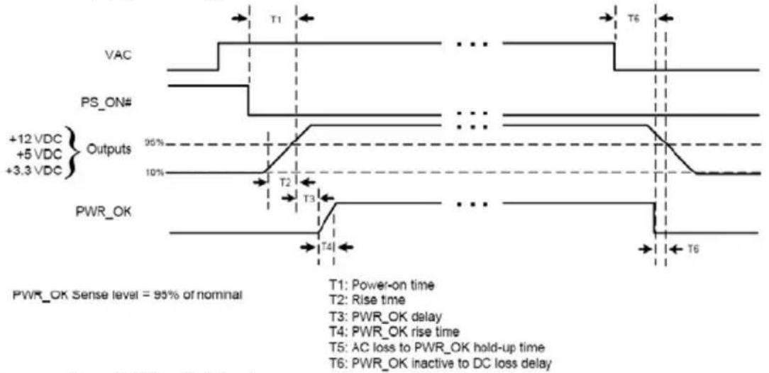
PG-OK is a power good signal and should be asserted high by power supply to indicate that the +5 VDC and +3.3 VDC outputs are above the under-voltage thresholds of the power supply. When this signal is asserted high, there should be sufficient mains energy stored by the converter to guarantee continuous power operation within specification. Conversely, when either the +5VDC or the +3.3VDC output voltage falls below the under-voltage threshold, or when mains power has been removed for a time sufficiently long so that power supply operation is no longer guaranteed, PG-OK should be deasserted to a low state. See Figure 1 for a representation of the timing characteristics of the PG-OK,PS-ON, and germane power rail signals.
3.8 3.3V Sense
A default 3.3V sense line should be implemented pin 13 of the connector.
3.9 Capacitive Load
The power supply should be able to power up and operate normally with the following capacitances simultaneously present on the DC outputs.
| Output | Capacitive load (uF) |
| +5V | 10,000 |
| +12V | 10,000 |
| +3.3V | 10,000 |
| -12V | 330 |
| +5VS | 10,000 |
4. Protection
4.1 Input Protection
In primary circuit of the power supply, a protected fuse is inserted. Only internal fault of the power supply will cause the fuse blown. Any overload or short circuit at DC output will keep from fuse brown or fire hazard.
4.2 Output Protection
4.2.1 Under voltage protection
The +5V/+12V/+3.3V DC output are protected against the under voltage condition. range value can't be exceed 3.3\~3.7V at 5V terminal and 8.5\~9.5V at 12V, 2.0\~2.4V at 3.3V.
4.2.2 Over Voltage Protection
The +12V/ DC output are protected against the over voltage condition. Maximum value can't be over 15.5V at 12V.
4.2.3 Over Power Protection
The power supply can be used electronic circuit to limit the output current against exceeding 10%-60% of surge output power or protected against excessive power delivery since short circuit of any output or over total power at high line.
4.2.4 Short Circuit Protection
Short circuit placed on +5V,+12V,+3.3V,-12V will latch off. +5VSB will auto-recovery.
4.2.5 Over-Current Protection
Current protection should be designed to limit the current to operate within safe operating conditions. Over current protection schemes where only the voltage output that experiences the over current event is shut off may be adequate to maintain safe operation of the power supply and the system; however, damage to the motherboard or other system components may occur. The recommended over current protection scheme is for the power supply to latch into the shutdown state. The setting of over current protection for each output rail is as following.
4.2.6 Over-Temperature Protection
This power supply includes an over-temperature protection sensor, which can trip and shut down the power supply at 110^ C
5. Start Stability
5.1 No Load Start
When power is applied to ST85F-PT with no load connected or under minimum load connected, neither damage to power supply nor hazards to users will occur.
5.2 Cold Start
The power supply shall operate properly when first applied at normal input voltage and or so maximum load after 4 hours storage in 0^ C environment.
6. Environments
6.1 Temperature and Humidity
6.1.1 Operating
Temperature ^ 0 to 40C
Relative Humidity 20 to 90 %
6.1.2 Storage
Temperature -40 to 70C
Relative Humidity 20 to 95 % noncondensing
6.2 Altitude
The power supply can operate normally at any altitude between 0 to 10000 feet.
6.3 Vibration and Shock
Sweep and resonance search for each of X,Y,Z, axis at the sweep.
RATE of 1/OCTAVE/Min.
| Frequency | Duration | Amplitude |
| 5-55-10 Hz | 30 minutes | 0.35 mm |
7. Conducted EMI
CE,FCC
8. Product Safety
8.1 Safety Requirement
cTUVus, CB, TUV
8.2 Leakage Current
The AC leakage current is less than 3.5mA when the power supply connect to 264Vac/50Hz.
8.3 Insulation Resistance
The insulation resistance should be not less than 30M ohm after applying of 500VDC for 1 minute.
8.4 Dielectric Voltage Withstand
The power supply shall withstand for 1 minute without breakdown the application of a 60Hz 1500V AC voltage applied between both input line and chassis (20mA DC cut-off current). Main transformer shall similarly withstand 3000Vac applied between both primary and secondary windings for a minimum of one minute.
9. Power Good Signal
A TTL compatible signal for the purpose of initiating an orderly start-up procedure under normal input operating conditions. During power up, this signal is asserted (low) until +5V is under regulation and AC reaches min. line specification range. After all voltage are going appropriate level, the system may have a turn on delay of 100mS, but no greater than 500mS. During power off the signal should go to low level before +5V is out of regulation. The low level is 0 to 0.8V and high level is 4.75 to 5.25V. The "Power Good" signal can drive up to 6 standard TTL loads.
Time Diagram
Figure 1
Power Supply Timing
other
| Signal | Time Step | |-----------------|-----------| | VAC | T1 | | PS_ON# | T6 | | Outputs | 95% | | PWR_OK | T4 | | Power-on time | T1: Power-on time | | Rise time | T2: Rise time | | PWR_OK delay | T3: PWR_OK delay | | Rise time | T4: PWR_OK rise time | | AC loss to PWR_OK hold-up | T5: AC loss to PWR_OK hold-up time | | PWR_OK inactive to DC loss delay | T6: PWR_OK inactive to DC loss delay |* T1 : Turn on time (500mS Max.)
* T2 : Rise time ( ≤ 20mS Max.)
* T3 : Power good turn on delay time ( 100 < T3 < 500 mS )
* T4 : Switch on time (10mS Max.)
* T5 : Power hold-on time ( 16 mS Min at 70%load)
* T6 : Power good turn off delay time ( 1.0 mS Min.)
* Power on-off cycle :
When the power supply is turned off for a minimum of 2.0 sec. and turn on again, the power good signal will be asserted.
10. MTBF
The MTBF of the power should be 100,000 hours min.
11. Burn-In
11.1 Input Voltage
Applying 220Vac.
11.2 Test Condition
Applying 75% loads for the power supply in 45 (+/-5) ^ C chamber for 4 hours.
12. Harmonics
The product shall meet requirement for EN61000-3-2 & EN61000-3-3 :1995 standard of class D, test at 230Vac 50Hz.
13. Power Factor
The power supply with active power factor correction, and meet the EN61000-3-2 standards. The power factor is greater than 0.9 at 230V/50Hz, Max. load.
14. Mechanical Specification
150 mm (W) × 86 mm (H) × 140mm (D)
SilverStone Technology Co., Ltd.
www.silverstonetek.com
support@silverstonetek.com
NO. G11226830
- STRIDER PLATINUM SERIES ST85F-PT
- World's smallest 80 PLUS Platinum, full-modular ATX power supplies
- SPECIFICATION
- SilverStone Strider Platinum
- SST-ST85F-PT
- ATX12V / EPS 12V Switching Power Supply
- With Active PFC
- 80Plus Platinum
- PS/2
- General
- Scope
- Input Characteristics
- Input Voltage
- Input Frequency
- Max. Input AC Current
- Inrush Current
- Efficiency
- Output characteristics
- Normal Operation Output
- NOTE:
- Remote On/Off Controlled mode
- Regulation
- Rise Time
- Hold-up Time
- 5VSB
- PG-OK
- 3.3V Sense
- Capacitive Load
- Protection
- Input Protection
- Output Protection
- Under voltage protection
- Over Voltage Protection
- Over Power Protection
- Short Circuit Protection
- Over-Current Protection
- Over-Temperature Protection
- Start Stability
- No Load Start
- Cold Start
- Environments
- Temperature and Humidity
- Operating
- Storage
- Altitude
- Vibration and Shock
- Conducted EMI
- Product Safety
- Safety Requirement
- Leakage Current
- Insulation Resistance
- Dielectric Voltage Withstand
- Power Good Signal
- Time Diagram
- Figure 1
- MTBF
- Burn-In
- Harmonics
- Power Factor
- Mechanical Specification
Brand : SILVERSTONE
Model : Strider ST85F-PT
Category : Mobile Device Charger