
LIBSESMG17UL - Electric battery APC - Free user manual and instructions
Find the device manual for free LIBSESMG17UL APC in PDF.


| Product Type | Uninterruptible Power Supply (UPS) |
| Model Number | LIBSESMG17UL |
| Brand | APC by Schneider Electric |
| VA / Watt Rating | 1700 VA / 1500 W |
| Input Voltage | 100-127 VAC |
| Output Voltage | 100-127 VAC (sine wave) |
| Input Frequency | 50/60 Hz +/- 3 Hz |
| Battery Type | Sealed Lead-Acid (SLA), replaceable |
| Typical Battery Life | 3-5 years |
| Recharge Time | 6-8 hours to 90% capacity |
| Number of Battery Outlets | 8 (battery backup + surge only) |
| Number of Surge Only Outlets | 2 |
| Surge Protection Rating | 1800 joules |
| Dimensions (H x W x D) | 14.3 x 6.7 x 11.3 inches (363 x 170 x 287 mm) |
| Weight | 24.3 kg (53.5 lbs) |
| Form Factor | Tower |
| USB/Serial Port | USB port for monitoring |
| LCD Display | Yes, for status and diagnostics |
| Operating Temperature | 32-104°F (0-40°C) |
| Noise Level | Less than 45 dBA |
| Warranty | 3 years |
Frequently Asked Questions - LIBSESMG17UL APC
User questions about LIBSESMG17UL APC
0 question about this device. Answer the ones you know or ask your own.
Ask a new question about this device
Download the instructions for your Electric battery in PDF format for free! Find your manual LIBSESMG17UL - APC and take your electronic device back in hand. On this page are published all the documents necessary for the use of your device. LIBSESMG17UL by APC.
USER MANUAL LIBSESMG17UL APC
Galaxy Lithium-ion Battery Cabinet
With 13, 16, or 17 Battery Modules
Installation and Operation
LIBSESMG13IEC, LIBSESMG16IEC, LIBSESMG17IEC
LIBSESMG13UL, LIBSESMG16UL, LIBSESMG17UL
Latest updates are available on the Schneider Electric website 5/2021
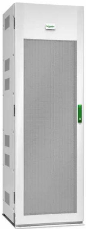
natural_image
Exterior view of a large industrial electrical cabinet (no visible text or symbols)Legal Information
The Schneider Electric brand and any trademarks of Schneider Electric SE and its subsidiaries referred to in this guide are the property of Schneider Electric SE or its subsidiaries. All other brands may be trademarks of their respective owners.
This guide and its content are protected under applicable copyright laws and furnished for informational use only. No part of this guide may be reproduced or transmitted in any form or by any means (electronic, mechanical, photocopying, recording, or otherwise), for any purpose, without the prior written permission of Schneider Electric.
Schneider Electric does not grant any right or license for commercial use of the guide or its content, except for a non-exclusive and personal license to consult it on an "as is" basis. Schneider Electric products and equipment should be installed, operated, serviced, and maintained only by qualified personnel.
As standards, specifications, and designs change from time to time, information contained in this guide may be subject to change without notice.
To the extent permitted by applicable law, no responsibility or liability is assumed by Schneider Electric and its subsidiaries for any errors or omissions in the informational content of this material or consequences arising out of or resulting from the use of the information contained herein.

Go to https://www.productinfo.schneider-electric.com/galaxyliion/ or scan the QR code above for digital experience and translated manuals.
Table of Contents
Important Safety Instructions — SAVE THESE
INSTRUCTIONS....5
FCC Statement 6
Electromagnetic Compatibility 6
Safety Precautions 6
Electrical Safety 8
Battery Safety 9
Specifications....10
Recommended Cable Sizes ....10
Recommended Cable Lugs 11
Torque Specifications....11
Weights and Dimensions....11
Clearance 12
Environment....12
Overview of Accessory Kits....13
Installation Procedure 14
Prepare for Installation ....15
Install the Rear Seismic Anchoring....17
Position and Interconnect the Battery Cabinets ....19
Install the Front Seismic Anchoring 21
Install the Battery Modules in the Battery Cabinet....22
Connect the Power Cables....25
Overview of Communication Interface....28
Route the Signal Cables to the Switchgear, Rack BMS, and System BMS
Ports 29
Overview of Signal Cables between the Battery Cabinets and the Auxiliary Contacts in the UPS 32
Overview of Signal Cables for Alarms and Battery Breaker Trip ....33
Overview of CAN Bus Cables between the Battery Cabinets ....34
Overview of EPO Signal Cables....34
Operation Procedures....35
Shut Down the Battery Solution ....35
Restart the Battery Solution....35
Troubleshooting 36
Status LEDs....36
PSU LEDs 37
Alarm List....38
Protection Protocols....38
Important Safety Instructions — SAVE THESE INSTRUCTIONS
Read these instructions carefully and look at the equipment to become familiar with it before trying to install, operate, service or maintain it. The following safety messages may appear throughout this manual or on the equipment to warn of potential hazards or to call attention to information that clarifies or simplifies a procedure.
The addition of this symbol to a “Danger” or “Warning” safety message indicates that an electrical hazard exists which will result in personal injury if the instructions are not followed.

This is the safety alert symbol. It is used to alert you to potential personal injury hazards. Obey all safety messages with this symbol to avoid possible injury or death.
⚠️ DANGER
DANGER indicates a hazardous situation which, if not avoided, will result in death or serious injury. Failure to follow these instructions will result in death or serious injury.
▲WARNING
WARNING indicates a hazardous situation which, if not avoided, could result in death or serious injury. Failure to follow these instructions can result in death, serious injury, or equipment damage.
▲CAUTION
CAUTION indicates a hazardous situation which, if not avoided, could result in minor or moderate injury. Failure to follow these instructions can result in injury or equipment damage.
NOTICE
NOTICE is used to address practices not related to physical injury. The safety alert symbol shall not be used with this type of safety message. Failure to follow these instructions can result in equipment damage.
Please Note
Electrical equipment should only be installed, operated, serviced, and maintained by qualified personnel. No responsibility is assumed by Schneider Electric for any consequences arising out of the use of this material.
A qualified person is one who has skills and knowledge related to the construction, installation, and operation of electrical equipment and has received safety training to recognize and avoid the hazards involved.
FCC Statement
NOTE: This equipment has been tested and found to comply with the limits for a Class A digital device, pursuant to Part 15 of the FCC Rules. These limits are designed to provide reasonable protection against harmful interference when the equipment is operated in a commercial environment. This equipment generates, uses, and can radiate radio frequency energy and, if not installed and used in accordance with the instruction manual, may cause harmful interference to radio communications. Operation of this equipment in a residential area is likely to cause harmful interference in which case the user will be required to correct the interference at his own expense.
Any changes or modifications not expressly approved by the party responsible for compliance could void the user's authority to operate the equipment.
Electromagnetic Compatibility
NOTICE
RISK OF ELECTROMAGNETIC DISTURBANCE
This is a product category C2 UPS product. In a residential environment, this product may cause radio inference, in which case the user may be required to take additional measures.
Failure to follow these instructions can result in equipment damage.
Safety Precautions
⚠️ DANGER
HAZARD OF ELECTRIC SHOCK, EXPLOSION, OR ARC FLASH
Read all instructions in the installation manual before installing or working on this product.
Failure to follow these instructions will result in death or serious injury.
⚠️ DANGER
HAZARD OF ELECTRIC SHOCK, EXPLOSION, OR ARC FLASH
- Do not install the product until all construction work has been completed and the installation room has been cleaned.
- Build a clear, permanent, restricted access area around the system.
Failure to follow these instructions will result in death or serious injury.
⚠️! DANGER
HAZARD OF ELECTRIC SHOCK, EXPLOSION, OR ARC FLASH
The product must be installed according to the specifications and requirements as defined by Schneider Electric. It concerns in particular the external and internal protections (upstream breakers, battery breakers, cabling, etc.) and environmental requirements. No responsibility is assumed by Schneider Electric if these requirements are not respected.
Failure to follow these instructions will result in death or serious injury.
⚠️ DANGER
HAZARD OF ELECTRIC SHOCK, EXPLOSION, OR ARC FLASH
The UPS system must be installed according to local and national regulations. Install the UPS according to:
- IEC 60364 (including 60364-4-41- protection against electric shock, 60364-4-42 - protection against thermal effect, and 60364-4-43 - protection against overcurrent), or
- NEC NFPA 70, or
• Canadian Electrical Code (C22.1, Part 1)
depending on which one of the standards apply in your local area.
Failure to follow these instructions will result in death or serious injury.
⚠️ DANGER
HAZARD OF ELECTRIC SHOCK, EXPLOSION, OR ARC FLASH
• Install the product in a temperature controlled indoor environment free of conductive contaminants and humidity.
- Install the product on a non-flammable, level and solid surface (e.g. concrete) that can support the weight of the system.
Failure to follow these instructions will result in death or serious injury.
⚠️ DANGER
HAZARD OF ELECTRIC SHOCK, EXPLOSION, OR ARC FLASH
The product is not designed for and must therefore not be installed in the following unusual operating environments:
- Damaging fumes
- Explosive mixtures of dust or gases, corrosive gases, or conductive or radiant heat from other sources
- Moisture, abrasive dust, steam or in an excessively damp environment
- Fungus, insects, vermin
- Salt-laden air or contaminated cooling refrigerant
- Pollution degree higher than 2 according to IEC 60664-1
- Exposure to abnormal vibrations, shocks, and tilting
- Exposure to direct sunlight, heat sources, or strong electromagnetic fields
Failure to follow these instructions will result in death or serious injury.
⚠️ DANGER
HAZARD OF ELECTRIC SHOCK, EXPLOSION, OR ARC FLASH
Do not drill or cut holes for cables or conduits with the gland plates installed and do not drill or cut holes in close proximity to the product.
Failure to follow these instructions will result in death or serious injury.
⚠️ ⚠️ WARNING
HAZARD OF ARC FLASH
Do not make mechanical changes to the product (including removal of cabinet parts or drilling/cutting of holes) that are not described in the installation manual.
Failure to follow these instructions can result in death, serious injury, or equipment damage.
▲WARNING
CHEMICAL HAZARD
This product can expose you to chemicals including Tetrabromobisphenol A, which is known to the State of California to cause cancer. For more information, go to www.P65Warnings.ca.gov
Failure to follow these instructions can result in death, serious injury, or equipment damage.
NOTICE
RISK OF OVERHEATING
Respect the space requirements around the product and do not cover the ventilation openings when the product is in operation.
Failure to follow these instructions can result in equipment damage.
Electrical Safety
⚠️ DANGER
HAZARD OF ELECTRIC SHOCK, EXPLOSION OR ARC FLASH
- Electrical equipment must be installed, operated, serviced, and maintained only by qualified personnel.
- Apply appropriate personal protective equipment (PPE) and follow safe electrical work practices.
- Turn off all power supplying the UPS system before working on or inside the equipment.
- Before working on the UPS system, check for hazardous voltage between all terminals including the protective earth.
- The battery cabinet contains an internal energy source. Hazardous voltage can be present even when the UPS system is disconnected from the utility/ mains supply. Before installing or servicing the UPS system, ensure that the units are OFF and that utility/mains and batteries are disconnected.
- A disconnection device (e.g. disconnection circuit breaker or switch) must be installed to enable isolation of the system from upstream power sources in accordance with local regulations. This disconnection device must be easily accessible and visible.
- The battery cabinet must be properly earthed/grounded and due to a high leakage current, the earthing/grounding conductor must be connected first.
Failure to follow these instructions will result in death or serious injury.
Battery Safety
⚠️ DANGER
HAZARD OF ELECTRIC SHOCK, EXPLOSION, OR ARC FLASH
- Battery circuit breakers must be installed according to the specifications and requirements as defined by Schneider Electric.
- Servicing of batteries must only be performed or supervised by qualified personnel knowledgeable of batteries and the required precautions. Keep unqualified personnel away from batteries.
- Disconnect charging source prior to connecting or disconnecting battery terminals.
- Do not dispose of batteries in a fire as they can explode.
- Do not open, alter, or mutilate batteries.
Failure to follow these instructions will result in death or serious injury.
⚠️! DANGER
HAZARD OF ELECTRIC SHOCK, EXPLOSION, OR ARC FLASH
Batteries can present a risk of electric shock and high short-circuit current. The following precautions must be observed when working on batteries
- Remove watches, rings, or other metal objects.
- Use tools with insulated handles.
- Wear protective glasses, gloves and boots.
- Do not lay tools or metal parts on top of batteries.
- Disconnect the charging source prior to connecting or disconnecting battery terminals.
- Determine if the battery is inadvertently grounded. If inadvertently grounded, remove source from ground. Contact with any part of a grounded battery can result in electric shock. The likelihood of such shock can be reduced if such grounds are removed during installation and maintenance (applicable to equipment and remote battery supplies not having a grounded supply circuit).
Failure to follow these instructions will result in death or serious injury.
⚠️! DANGER
HAZARD OF ELECTRIC SHOCK, EXPLOSION, OR ARC FLASH
When replacing batteries, always replace with the same battery module type.
Failure to follow these instructions will result in death or serious injury.
NOTICE
RISK OF EQUIPMENT DAMAGE
- Batteries should not be stored beyond 12 months from the date of production. If they are stored for longer the calendar degradation will cause the batteries to be irreversible degraded beyond what is expected – a reduced runtime will be the consequence. Performance guarantee will be measured from the time of deployment or from production date +12 months whichever comes first. For storage beyond 12 months, contact Schneider Electric.
- If the UPS system remains de-energized for a long period, Schneider Electric recommends to shut down the battery cabinet completely.
Failure to follow these instructions can result in equipment damage.
Specifications
| Commercial reference LIBSE$MG13IEC/LIBSESMG13UL | LIBSESMG16IEC/LIBSESMG16UL | LIBSESMG17IEC/LIBSESMG17UL | |
| Battery designation IMP46/175/127/[(8S)13S]M/-20+60/90 | IMP46/175/127/[(8S)16S]M/-20+60/90 | IMP46/175/127/[(8S)17S]M/-20+60/90 | |
| Number of battery modules 13 | 16 17 | ||
| Number of type A battery modules (LIBSMG95MODA) | 6 8 8 | ||
| Number of type B battery modules (LIBSMG95MODB) | 7 8 9 | ||
| Number of battery cells in a string | 104 128 136 | ||
| Nominal energy (kWh) 26.5 32.6 | 34.6 | ||
| Nominal battery voltage (VDC) | 395 486 517 | ||
| Nominal capacity (Ah) 67 67 67 | |||
| Charge current rate (CA rate) | 0.7 0.7 0.7 | ||
| Float charge voltage (VDC) 436 | 537 571 | ||
| End of discharge voltage (VDC) | 312 384 408 | ||
| Maximum continuous discharge power (kW) | 140 173 184 | ||
| Peak current at end of discharge (A) | 450 450 450 | ||
| Maximum short circuit current (kA) | 9.0 9.0 9.0 | ||
NOTE: If the battery temperature is higher than the threshold after a full discharge at maximum continuous discharge power, the UPS may have to reduce the charge current to zero to protect the battery.
NOTE: The battery temperature must return to ±3 ^/±37.4 ^ of the room temperature before a new discharge at maximum continuous discharge power. If not, the battery breaker may be tripped due to overtemperature protection.
Recommended Cable Sizes
⚠️! DANGER
HAZARD OF ELECTRIC SHOCK, EXPLOSION, OR ARC FLASH
All wiring must comply with all applicable national and/or electrical codes. The maximum allowable cable size is 185 mm^2 (IEC) / 350 kcmil (UL).
Failure to follow these instructions will result in death or serious injury.
NOTE: Refer to the UPS installation manual for recommended cable sizes.
Recommended Cable Lugs
Copper – One Hole Cable Lug
| Cable size Bolt size Cable lug type Crimp tool Die | ||||
| 3/0 AWG M10x30 LCA3/0-12-X CT-720 CD-720-2 | Orange P50 | |||
| 4/0 AWG M10x30 LCA4/0-12-X CT-720 CD-720-3 | Purple P54 | |||
| 300 kcmil M10x30 LCA300-12-X CT-720 CD-720-4 | White P66 | |||
| 350 kcmil M10x30 LCA350-12-X CT-720 CD-720-5 | Red P71 | |||
Copper - Two Hole Cable Lug
| Cable size Bolt size Cable lug type Crimp tool Die | |||||
| 3/0 AWG M10x30 LCC3/0-12D-X | CT-930 | CD-920-3/0 Orange P50 | |||
| 4/0 AWG M10x30 LCC4/0-12D-X | CT-930 | CD-920-4/0 Purple P54 | |||
| 300 kcmil M10x30 LCC300-12-X | CT-930 | CD-920-300 White P66 | |||
| 350 kcmil M10x30 LCC350-12-X | CT-930 | CD-920-350 Red P71 | |||
Torque Specifications
| Bolt size | Torque |
| M4 | 1.7 Nm (1.25 lb-ft) |
| M6 | 5 Nm (3.69 lb-ft) |
| M8 | 14 Nm (10.33 lb-ft) |
| M10 | 30 Nm (22.13 lb-ft) |
| M12 | 46 Nm (33.93 lb-ft) |
Weights and Dimensions
| Commercial reference | Weight kg (lbs) | Height mm (in) | Width mm (in) | Depth mm (in) |
| LIBSESMG13IEC/LIBSESMG13UL | 415 (915) | 1970 (77.56) | 650 (25.59) | 587 (23.11) |
| LIBSESMG16IEC/LIBSESMG16UL | 470 (1036) | 1970 (77.56) | 650 (25.59) | 587 (23.11) |
| LIBSESMG17IEC/LIBSESMG17UL | 490 (1080) | 1970 (77.56) | 650 (25.59) | 587 (23.11) |
Clearance
NOTE: Clearance dimensions are published for airflow and service access only. Consult with the local safety codes and standards for additional requirements in your local area.

* For system with seismic anchoring.
Environment
| Operating Storage | ||
| Temperature Recommended operating temperature: 18 to 28 °C (64 to 82 °F) | Battery cabinet: 0 °C to 40 °C (32 °F to 104 °F)Battery modules: Recommended storage for battery modules is 20 °C (68 °F) or cooler (non-freezing) | |
| Relative humidity 0-95% non-condensing Battery cabinet: 0-90% non-condensing | Battery modules: Recommended storage for battery modules is 40-80% non-condensing | |
| Elevation 0-3000 m (0-10000 feet) | ||
| Protection class IP20 | ||
| Color RAL 9003, gloss level 85% | ||
Overview of Accessory Kits
Accessory Kit 0M-95318: Busbar Kit
NOTE: Save this accessory kit for the field service representative. The busbars will be installed by Schneider Electric during the start-up service.
Accessory Kit 0M-95319: Cover Kit
NOTE: Save this accessory kit for the field service representative. The covers will be installed by Schneider Electric during the start-up service.
Accessory Kit 0M-95320: Cable Kit
| Part Number Description Quantity | Used in | ||
| 0W76926 Signal cable from battery module to battery module - standard | 15 Note: Save these signal cables for the field service representative. These signal cables will be installed by Schneider Electric during the start-up service. | ||
| 0W76936 Signal cable from battery module to battery module - long | 1 | ||
| 0W76933 Signal cable from battery module to RBMS | 1 | ||
| 0W76928 Signal cable from RBMS CAN 2 to RBMS CAN 1 in next battery cabinet | 1 Route the | Signal Cables to the Switchgear, Rack BMS, and System BMS Ports, page 29 | |
| 0W76929 Signal cable from MCCB AUX 1 to UPS | 1 | ||
| 0W76934 Signal cable from MCCB AUX 2 to MCCB AUX 1 in next battery cabinet | 1 | ||
| 0W13444 Signal cable from SGB I/O | 1 to the UPS | 1 | |
| 0W13442 Signal cable from SGB I/O | 2 to the UPS | 1 | |
| 0W76972 Signal cable from SGB I/O | 1 to SGB I/ O 1 between the battery cabinets | 1 | |
Accessory Kit 0M-95331: Seismic Anchoring and Fuse Kit
| Part Number Description Quantity | Used in | ||
| 870-50102 Anchor parts 4 Install the | Rear Seismic Anchoring, | page 17 | |
| 870-51172 Interconnection plate between seismic brackets | 1 | ||
| 803-0684 | M6 x 12 torx screw with washer | 4 | |
| 803-0686 | M6 x 16 torx with washer | 18 | Install the Rear Seismic Anchoring, page 17 and Position and Interconnect the Battery Cabinets, page 19 |
| TME00409 | 500 A fast acting fuse | 3 Note: | Save for the field service representative. The fuses will be installed by Schneider Electric during the start-up service. |
| HUA29593 | Washer | 6 | |
| HUA13751 | M12 x 16 hexagonal screw | 6 | |
| HUA41574 | 3 A rated fuse | 2 |
Installation Procedure
- Prepare for Installation, page 15.
- Install the Rear Seismic Anchoring, page 17.
- Position and Interconnect the Battery Cabinets, page 19.
- Install the Front Seismic Anchoring, page 21.
- Install the Battery Modules in the Battery Cabinet, page 22.
- Connect the Power Cables, page 25.
- Route the Signal Cables to the Switchgear, Rack BMS, and System BMS Ports, page 29.
Prepare for Installation
- Remove the indicated cover.
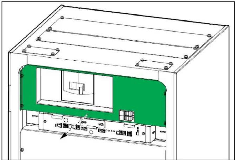
natural_image
Technical line drawing of an electronic device casing with internal components and mounting brackets (no text or symbols)- Remove the two transparent covers.
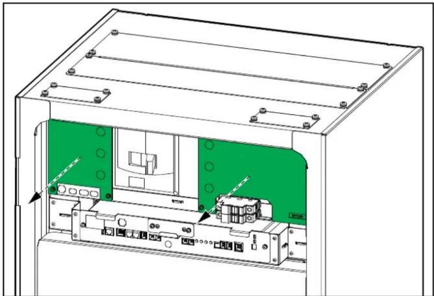
natural_image
Technical line drawing of an electronic device chassis showing internal components and mounting brackets (no text or symbols)- Remove the plate in front of the battery shelves.

natural_image
Technical line drawing of a rectangular electronic device with internal components and directional arrows indicating flow or movement (no text or symbols)- Remove the four boxes with accessory kits from the bottom of the cabinet. Refer to Overview of Accessory Kits, page 13 for more information on the accessory kits.

natural_image
Technical diagram of a multi-chamber electrical enclosure with green panel compartments and mounting brackets (no text or symbols)Install the Rear Seismic Anchoring
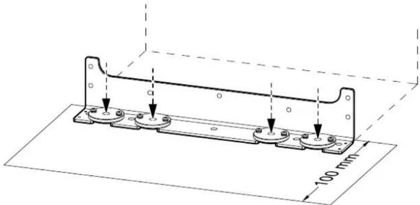
- Mount the rear seismic assembly (4 x 870-50102 and M6 x 16 torx screws from accessory kit 0M-95331 and the rear shipping bracket) to the floor. Use appropriate hardware for the floor type – the hole diameter in the rear seismic bracket is 14 mm. The minimum requirement is M12 strength grade 8.8 hardware.
Rear View
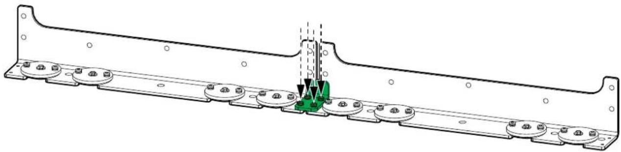
- In systems with more battery cabinets, interconnect the seismic assemblies with the interconnection plate 870-51172 from the accessory kit OM-95331.
Rear View
natural_image
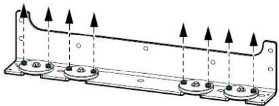
Technical line drawing of a mechanical assembly with mounting flanges and a green component inserted (no text or symbols)- Remove the indicated screws.
Rear View
natural_image
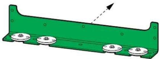
Technical diagram of a mechanical component with multiple circular features and upward-pointing arrows indicating force or direction (no text or symbols present)- Remove the rear seismic bracket.
Rear View
natural_image
Green metal bracket with four circular components and a dashed arrow indicating direction (no text or symbols)- Install the rear seismic bracket on the battery cabinet(s).
Rear View
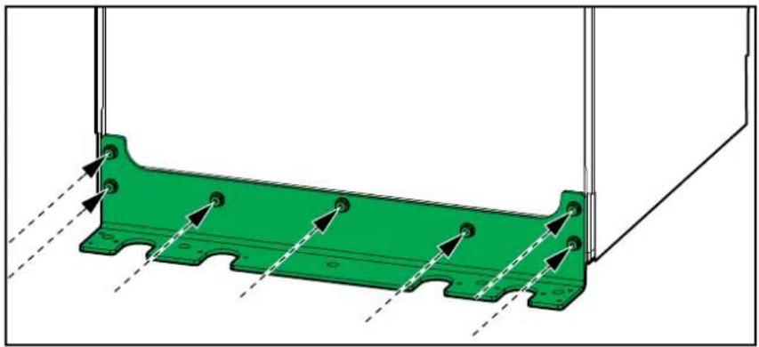
natural_image
Green mechanical bracket with mounting holes and dashed alignment lines (no text or symbols)Position and Interconnect the Battery Cabinets
NOTE: This procedure describes how to position and interconnect several battery cabinets. If your system only has one battery cabinet, you only need to follow step 2 and step 3.
- Remove the side panels that are adjacent to the other battery cabinets.
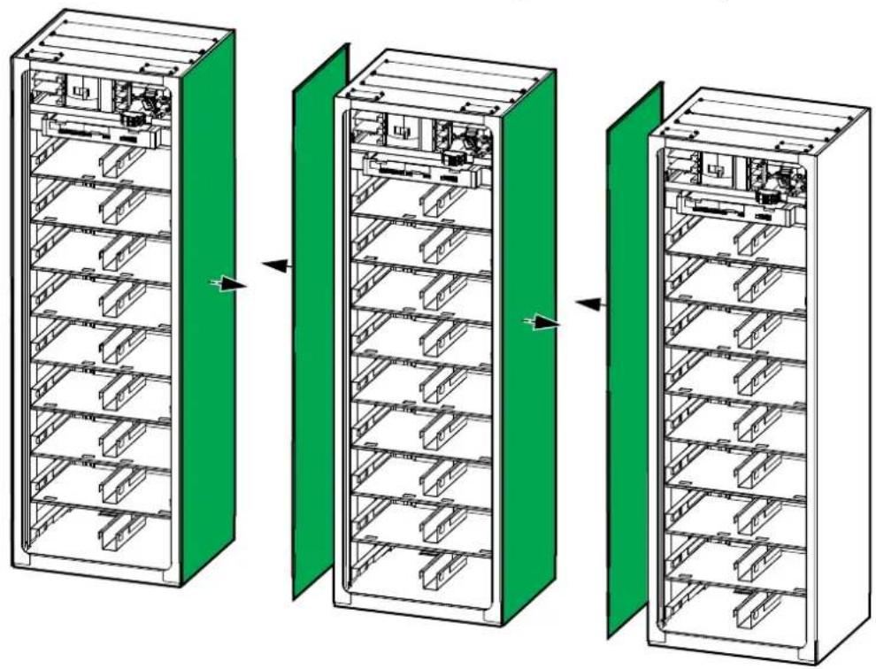
natural_image
Three-step diagram showing internal storage racks in green-shaded compartments, no text or symbols present- Push the right-most battery cabinet into position. For seismic anchoring, ensure that the rear seismic bracket connects to the rear anchors.
Rear View

natural_image
Green electronic component with mounting holes and a black arrow indicating direction (no text or symbols)- Lower the levelling feet until they connect with the floor - use a bubble-leveler to ensure that the cabinet is level.

natural_image
Technical line drawing of a mechanical component with arrows indicating force or movement (no text or symbols)-
Push the second right-most battery cabinet into position, align with the seismic anchoring (if any), and level the battery cabinet as described in step 2 and step 3.
-
Install the ten interconnection screws (five in the front and five in the rear) between the two battery cabinets.
NOTE: To reach the five interconnection screws in the rear of the left-most battery cabinet, the left side panel can be removed. Reinstall the left side panel on the left-most battery cabinet after interconnection.
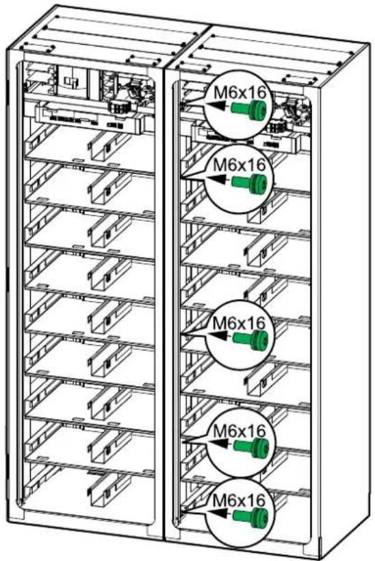

- Push the third battery cabinet into position, align with the seismic anchoring (if any), level the battery cabinet, and interconnect with the other battery cabinets as described in step 2, step 3, and step 5. Continue until all the battery cabinets are in place, levelled, and interconnected.
Install the Front Seismic Anchoring
- Install the front seismic bracket (front shipping bracket) on the battery cabinet.

natural_image
Technical diagram of a green metal bracket with mounting holes and dashed alignment lines (no text or symbols)- Anchor the front seismic bracket to the floor using appropriate hardware for the floor type – the hole diameter in the front seismic bracket is 14 mm. The minimum requirement is M12 strength grade 8.8 hardware.
NOTE: Floor anchoring bolts are not supplied.
Install the Battery Modules in the Battery Cabinet
Type A Battery Module Type B Battery Module
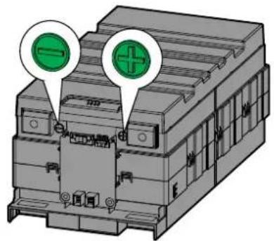

⚠️ ⚠ WARNING
HAZARD OF INJURY AND ELECTRIC SHOCK
- Be careful when installing and removing the battery modules (>17 kg).
Failure to follow these instructions can result in death, serious injury, or equipment damage.
- Install the battery modules on the shelves from top to bottom.
NOTE: Pay special attention to the location of type A and type B battery modules.
Battery Configurations for Battery Cabinets with 17, 16, and 13 Battery Modules
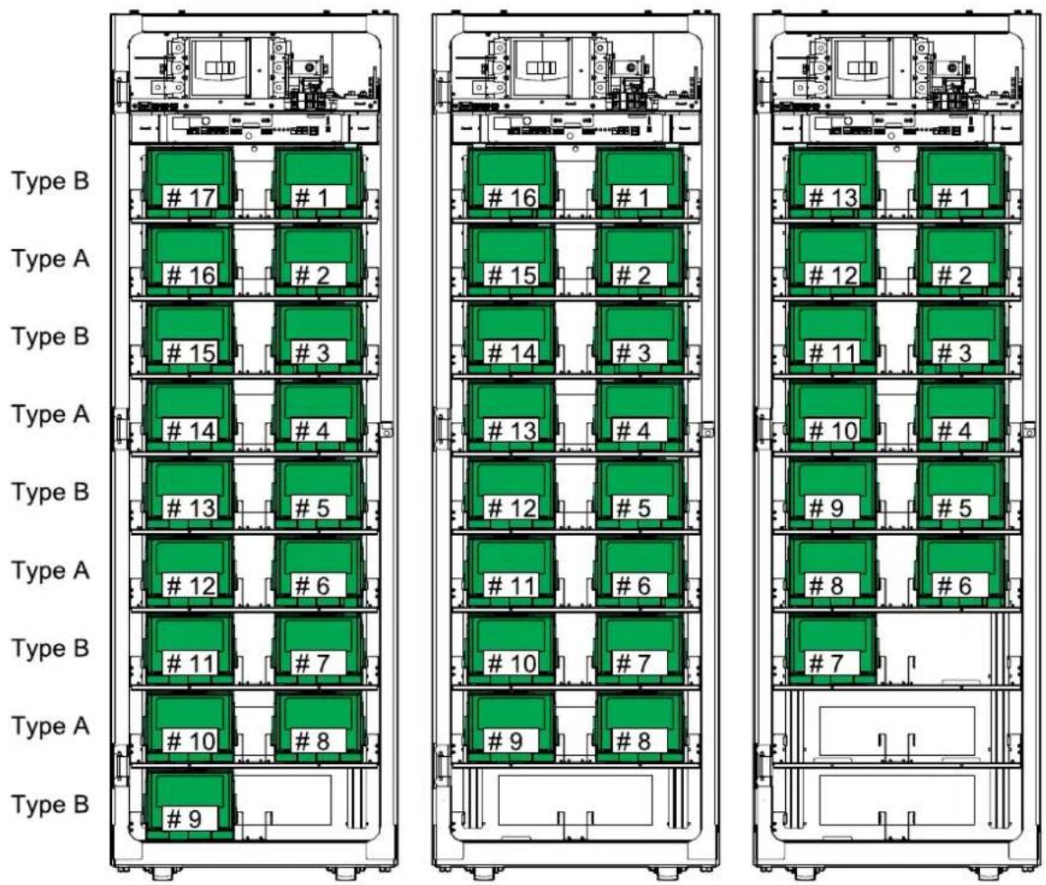
- Reinstall the plate in front of the battery shelves.

natural_image
Technical line drawing of a rectangular electronic device with internal components and directional arrows indicating flow or movement (no text or symbols)Connect the Power Cables
⚠️ DANGER
HAZARD OF ELECTRIC SHOCK, EXPLOSION, OR ARC FLASH
Do not drill or punch holes with the gland plates installed and do not drill or punch holes in close proximity to the battery cabinet.
Failure to follow these instructions will result in death or serious injury.
- Remove the gland plates.

- Drill or punch holes for cables/conduits in the rear gland plate according to the label on the gland plate.
⚠️ DANGER
HAZARD OF ELECTRIC SHOCK, EXPLOSION, OR ARC FLASH
Ensure that there are no sharp edges that can damage the cables.
Failure to follow these instructions will result in death or serious injury.
-
Install conduits (if applicable) and reinstall the gland plates.
-
Route the power cables through the gland plate and connect to the terminals:
a. Connect the PE cable to the PE terminal/Connect the EGC cable to the grounding terminal.
b. For installations with two hole cable lugs only, temporarily remove the protection cover.
NOTE: The protection cover must be reinstalled when the DC-cable has been connected.
c. Connect the DC+ and DC- cables to the DC+ and DC- terminals.
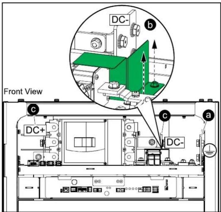

- Connect the power cables in the UPS. If more battery cabinets are part of the solution, connect all battery cabinets to the UPS according to the diagram below.
NOTE: If the combined short circuit current of the battery cabinets exceeds the short circuit rating of the UPS, a pull box with fuses or an external box with a battery breaker must be installed. Please contact Schneider Electric for more information and refer to the submittal drawings for your specific UPS.

flowchart
graph TD
    A["Battery cabinet 4"] --> B["DC+"]
    C["Battery cabinet 3"] --> D["DC+"]
    E["Battery cabinet 2"] --> F["DC+"]
    G["Battery cabinet 1"] --> H["DC+"]
    I["UPS"] --> J["DC+"]
    I --> K["DC-"]
    style A fill:#f9f,stroke:#333
    style C fill:#f9f,stroke:#333
    style E fill:#f9f,stroke:#333
    style G fill:#f9f,stroke:#333
    style I fill:#ccf,stroke:#333
    style I fill:#ccf,stroke:#333
    style I fill:#ccf,stroke:#333
- Reinstall the two transparent covers.

natural_image
Technical line drawing of an electronic device chassis showing internal components and mounting brackets (no text or symbols)Overview of Communication Interface

A. TCP/IP
B. Dry contact
C. SMPS I/O
D. CAN I/O
E. RS485
F. System BMS CAN I/O
G. DC OUT 1 and DC OUT 2
H. Reset switch
I. Start-up button
J. DC IN 1 and DC IN 2
K. Status LEDs
L. CAN bus loop termination resistor switch
M. CAN 1 port, CAN 2 port
N. Module
O. EPO
P. PSU 1 and PSU2 LEDs
Q. SG IO 1
R. SG IO 2
S. MCCB AUX 1
T. MCCB AUX 2
Route the Signal Cables to the Switchgear, Rack BMS, and System BMS Ports
⚠️ DANGER
HAZARD OF ELECTRIC SHOCK, EXPLOSION, OR ARC FLASH
Do not drill or punch holes with the gland plates installed and do not drill or punch holes in close proximity to the battery cabinet.
Failure to follow these instructions will result in death or serious injury.
NOTE: Please refer to the UPS submittal drawings to get a complete overview of the connections before preparing for and routing the signal cables.
NOTE: The signal cables provided with the battery cabinet are 5 m (16.4 ft) long. A 25 m (82 ft) signal cable kit LIBSEOPT001 can be ordered from Schneider Electric.
- Remove the gland plates for signal cables.

natural_image
Technical line drawing of an electronic device chassis with green connectors and internal components (no text or symbols)- Drill or punch holes for cables/conduits and install conduits (if applicable).
⚠️ DANGER
HAZARD OF ELECTRIC SHOCK, EXPLOSION, OR ARC FLASH
Ensure that there are no sharp edges that can damage the cables.
Failure to follow these instructions will result in death or serious injury.
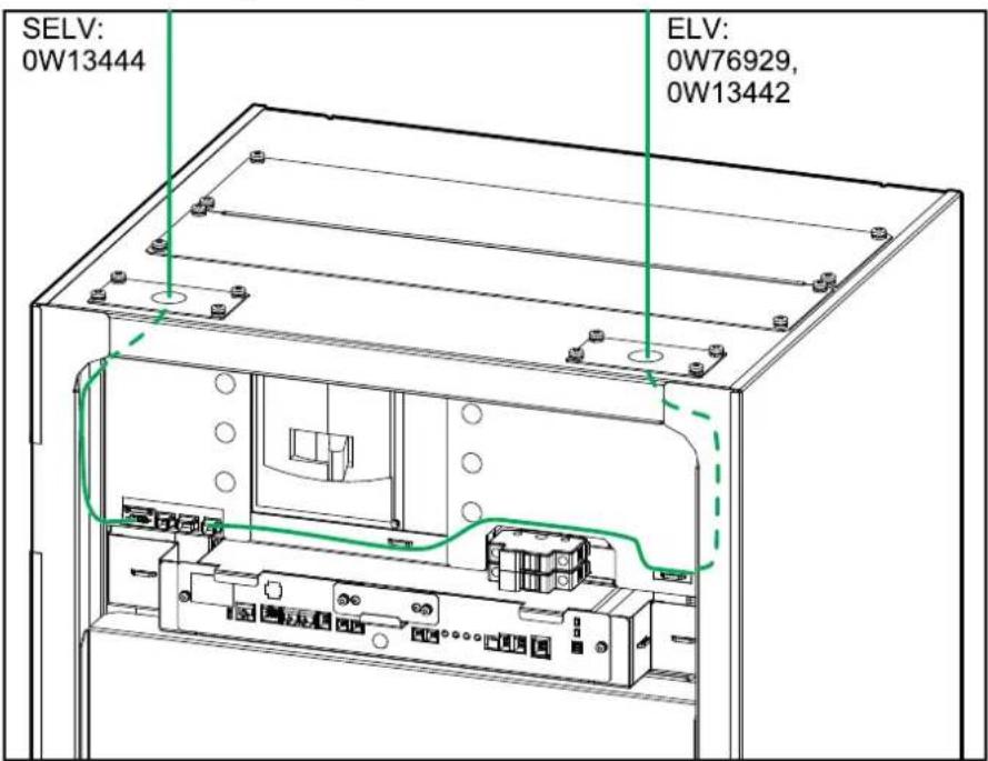
- Route the SELV signal cable 0W13444 and the ELV signal cables 0W76929 and 0W13442 into the battery cabinet and to the switchgear ports. Do not connect the signal cables, Schneider Electric service will complete the connections during start-up.
- Route the signal cable 0W76928, 0W76934, and 0W76972 through the openings in the sides of the battery cabinets and to the ports in the rack BMS and the switchgear ports. Do not connect the signal cables, Schneider Electric service will complete the connections during start-up.
NOTE: All cables between rack BMS and rack BMS as well as between system BMS and rack BMS are considered Class 2/SELV.

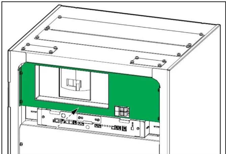
- Reinstall the plate in front of the battery breaker.
natural_image
Technical line drawing of an electronic device casing with internal components and mounting brackets (no text or symbols)-
Reinstall the front door of the battery cabinet.
-
Install the temperature sensor provided with the UPS above the battery cabinet, approximately 300 mm (12 in) from the top. Route the signal cable to the UPS and connect according to the instructions in the UPS installation manual.

NOTE: The temperature sensor measures the ambient temperature. Do not place the temperature sensor close to external heating or cooling equipment which may give an incorrect measurement of the ambient temperature.
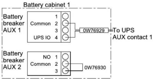
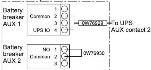
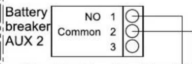
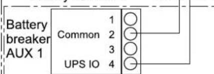
Overview of Signal Cables between the Battery Cabinets and the Auxiliary Contacts in the UPS
The connection of auxiliary contacts is dependent on the number of battery breakers supported by the UPS. In the examples below two banks of battery breakers are supported.
NOTE: If the combined short circuit current of the battery cabinets exceeds the short circuit rating of the UPS, a pull box with fuses or an external box with a battery breaker must be installed. Please contact Schneider Electric for more information.
System with One Battery Cabinet


System with Two Battery Cabinets
Battery cabinet 2
System with Four Battery Cabinets in Two Battery Banks
Battery bank 2


Battery cabinet 4


Battery bank 1

flowchart
graph LR
    A["Battery cabinet 1"] --> B["Battery breaker AUX 1"]
    B --> C["Common 1 2 3 4"]
    C --> D["0W76929"]
    D --> E["To UPS AUX contact 1"]
Battery cabinet 2

Overview of Signal Cables for Alarms and Battery Breaker Trip
Only the system BMS of battery cabinet 1 (cabinet closest to the UPS) is connected to the UPS.
- SG IO 1: Used for sending signals for minor and major alarms to the UPS.
• SG IO 2: Used for receiving trip signal from the UPS.
System with One Battery Cabinet


System with Three Battery Cabinets in Two Battery Banks

flowchart
graph LR
    subgraph_Battery_bank_1["Battery bank 1"]
        A1["SG IO 1: MA+ 1, MA- 2, MI+ 3, MI- 4"] --> B1["SG IO 1: MA+ 1, MA- 2, MI+ 3, MI- 4"]
    end
    subgraph_Battery_bank_2["Battery bank 1"]
        A2["SG IO 2: BB Trip 1, GND 3"] --> B2["SG IO 2: BB Trip 1, GND 3"]
    end
    subgraph_Battery_bank_3["Battery bank 3"]
        A3["SG IO 1: MA+ 1, MA- 2, MI+ 3, MI- 4"] --> B3["SG IO 1: MA+ 1, MA- 2, MI+ 3, MI- 4"]
    end
    B1 --> C1["0W76972"]
    B2 --> C2["0W76972"]
    B3 --> C3["0W76972"]
    C1 --> D1["0W13444: To UPS input contacts"]
    C2 --> D2["0W13442: To BB trip in UPS"]
    C3 --> D3["0W13442: To UPS input contacts"]
Overview of CAN Bus Cables between the Battery Cabinets
NOTE: In systems with more battery cabinets, remove the cables 0W76935 from CAN 1 in the rack BMS to the System BMS CAN I/O except in battery cabinet 1.
- Route signal cable 0W76928 from CAN 2 port of battery cabinet 1 to the CAN 1 port of battery cabinet 2. Repeat for the remaining battery cabinets. Do not connect the CAN cables, Schneider Electric service will complete the connections during start-up.

Overview of EPO Signal Cables
Connect the Class 2/SELV signal cables from the building EPO to the rack BMS. Class 2/SELV circuits must be isolated from the primary circuitry. Do not connect any circuit to the EPO terminal block unless it can be confirmed that the circuit is Class 2/SELV.

Operation Procedures
Shut Down the Battery Solution
NOTE: This procedure is only for a short temporary shutdown of the battery solution. If the battery solution should remain shut down for a longer period, please contact Schneider Electric.
⚠️ DANGER
HAZARD OF ELECTRIC SHOCK, EXPLOSION OR ARC FLASH
The battery cabinet contains an internal energy source. Hazardous voltage is still present after the battery breaker has been opened.
Failure to follow these instructions will result in death or serious injury.
- Manually set the battery breaker of each individual battery cabinet to the OFF (open) position to disconnect the battery power from the UPS.
NOTE: The system BMS and rack BMS will still be operating.
Restart the Battery Solution
- Perform the following steps on all battery cabinets in the battery solution.
a. Remove the cover in front of the start-up button and push the start-up button.
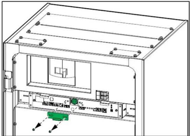
natural_image
Technical line drawing of an electronic device chassis with labeled ports and internal components (no text or symbols)• The PSU2 LED and the POWER LED will turn on.
- The ABNORMAL and ALARM LEDs should remain off.

b. Reinstall the cover in front of the start-up button.
c. Set the battery breaker to the ON (closed) position.
Troubleshooting
Status LEDs
| LED | Battery Status | Description | |||
ABNORMAL |  | CURRENT | Normal | The battery breaker is in the OFF(open) position. | |
ABNORMAL |  | CURRENT | Normal | The battery breaker is in the ON(closed) position. | |
ABNORMAL |  | CURRENT | Normal The batteries are being discharged. | ||
ABNORMAL |  | CURRENT | Normal The batteries are being recharged. | ||
ABNORMAL |  | CURRENT | Major alarm The battery breaker has trippedand is in the OFF (open) position | ||
ABNORMAL |  | CURRENT | Minor alarm | The battery breaker is in the ON(closed) position. | |
PSU LEDs

- When the LED is green, the PSU is powered ON.
- When the LED is OFF, the PSU is powered OFF or inoperable.
Alarm List
Protection Protocols
Protection Protocol for Battery Cabinet with 17 Battery Modules
| No | Item Level Set condition Soft- | ware set time (sec) | Battery breaker status1 | Release condition Time (sec) | Battery breaker status | ||
| 1 | Over voltage protection - cell | Major Max cell ≥ 4.28 V 5 | OFF Max cell <4.25 V and reset | 5 | ON | ||
| 2 | Under voltage protection - cell | Major Min cell ≤ 2.5 V | 3 OFF | Min cell > 2.70 V and reset | 3 | ON | |
| 3 | Over voltage protection - cabinet | Major Cabinet voltage ≥ 582.08 V | 5 | OFF Cabinet voltage < 578 V and reset | 5 | ON | |
| 4 | Under voltage protection - cabinet | Major Cabinet voltage ≤ 340 V | 3 OFF | Cabinet voltage > 367.2 V and reset | 3 | ON | |
| 5 | Voltage imbalance Major Max | cell ≥ 3.80 V and △Vcell ≥ 100 mV | 5 | OFF △Vcell 30 mV and reset 5 | ON | ||
| 6 | Voltage sensing error (cabinet) | Minor Cabinet V- cell sum V| ≥40.8 V | 10 | ON | [Rack V- cell sum V] < 20.4 V and reset | 3 | ON |
| 7 | Voltage sensing error (module) | Minor | Module V- cell sum V| ≥190 mV | 5 | ON | [Module V- cell sum V] < 190 mV and reset | 3 | ON |
| 8 | Over temperature protection | Major Max temp ≥ 75 °C | 3 | OFF | Max temp < 65 °C and reset | 3 | ON |
| 9 | Under temperature protection | Minor Min temp ≤ 0 °C | 3 | ON | Min temp > 5°C & reset | 3 | ON |
| 10 | Temperature imbalance | Major Max cell T-min cell T ≥ 40 °C | 30 | OFF Max cell T-min cell T < 20 °C and reset | 3 | ON | |
| 11 | Over current protection (charge) | Major Level2 current ≥ 250 A 2 | OFF |Current| < 10 A and reset | 3 | ON | ||
| Major Level1 current ≥ 200 A 60 | OFF |Current| < 10 A and reset | 3 | ON | ||||
| 12 | Over current protection (discharge) | Major Level4 |current| ≥ 600 A | 1 OFF | |Current| < 10 A and reset | 3 | ON | |
| Major Level3 |current| ≥ 540 A | 10 | OFF |Current| < 10 A and reset | 3 | ON | |||
| Major Level2 |current| ≥ 495 A | 30 | OFF |Current| < 10 A and reset | 3 | ON | |||
| Major Level1 |current| ≥ 470 A | 60 | OFF |Current| < 10 A and reset | 3 | ON | |||
| 13 | Communication lost (module ↔ cabinet) | Major No communication | 30 | OFF Communication reestablished + reset | - | ON | |
| 14 | Communication lost (cabinet ↔ system ) | Minor No communication | 30 | ON Communication reestablished + reset | - | ON | |
| 15 | SW failure - battery breaker | Minor Battery breaker OFF and |current| ≥ 2.4 A | 3 ON | (Battery breaker OFF and (|current| < 2.4 A) and reset | - | ON | |
| 16 | SW sensor failure - battery breaker | Minor Battery breaker contact ON = battery breaker trip ON | 3 ON | (Battery breaker contact ≠ battery breaker trip) and reset | - | ON | |
| 17 | Current sensing error | Minor No communication with Current IC | 3 ON | Communication with current IC OK | - | ON | |
| 18 | Fuse failure | Minor Fuse blown | 10 | ON | Fuse ON and reset | - | ON |
Protection Protocol for Battery Cabinet with 16 Battery Modules
| No | Item Level Set condition Soft- | ware set time (sec) | Battery breaker status2 | Release condition Time (sec) | Battery breaker status | |
| 1 | Over voltage protection - cell | Major Max cell ≥ 4.28 V 5 | OFF Max cell < 4.25 V and reset | 5 | ON | |
| 2 | Under voltage protection - cell | Major Min cell ≤ 2.5 V 3 OFF | Min cell > 2.70 V and reset | 3 | ON | |
| 3 | Over voltage protection - cabinet | Major Cabinet voltage ≥ 547.84 V | 5 | OFF Cabinet voltage < 544 V and reset | 5 | ON |
| 4 | Under voltage protection - cabinet | Major Cabinet voltage ≤ 320 V | 3 OFF | Cabinet voltage > 345.6 V and reset | 3 | ON |
| 5 | Voltage imbalance Major Max | cell ≥ 3.80 V and △Vcell ≥ 100 mV | 5 | OFF △Vcell < 30 mV and reset | 5 | ON |
| 6 | Voltage sensing error (cabinet) | Minor Cabinet V - cell sum V ≥38.4 V | 10 | ON | |Rack V - cell sum V| < 19.2 V and reset | 3 |
| 7 | Voltage sensing error (module) | Minor |Module V - cell sum V| ≥190 mV | 5 | ON | |Module V - cell sum V| < 190 mV and reset | 3 |
| 8 | Over temperature protection | Major Max temp ≥ 75 °C | 3 | OFF | Max temp < 65 °C and reset | 3 |
| 9 | Under temperature protection | Minor Min temp ≤ 0 °C | 3 | ON | Min temp > 5°C & reset | 3 |
| 10 | Temperature imbalance Major Max cell T - min cell T ≥ 40 °C | 30 | OFF Max cell T - min cell T < 20 °C and reset | 3 | ON | |
| 11 | Over current protection (charge) | Major Level2 current ≥ 250 A 2 | OFF |Current| < 10 A and reset | 3 | ON | |
| Major Level1 current ≥ 200 A 60 | OFF |Current| < 10 A and reset | 3 | ON | |||
| 12 | Over current protection (discharge) | Major Level4 |current| ≥ 600 A | 1 OFF |Current| < 10 A and reset | 3 | ON | |
| Major Level3 |current| ≥ 540 A | 10 | OFF |Current| < 10 A and reset | 3 | ON | ||
| Major Level2 |current| ≥ 495 A | 30 | OFF |Current| < 10 A and reset | 3 | ON | ||
| Major Level1 |current| ≥ 470 A | 60 | OFF |Current| < 10 A and reset | 3 | ON | ||
| 13 | Communication lost (module ↔ cabinet) | Major No communication | 30 | OFF Communication reestablished + reset | - | ON |
| 14 | Communication lost (cabinet ↔ system ) | Minor No communication | 30 | ON Communication reestablished + reset | - | ON |
| 15 | SW failure - battery breaker | Minor Battery breaker OFF and |current| ≥ 2.4 A | 3 ON (Battery breaker OFF and (|current| < 2.4 A) and reset | - | ON | |
| 16 | SW sensor failure - battery breaker | Minor Battery breaker contact ON = battery breaker trip ON | 3 ON (Battery breaker contact ≠ battery breaker trip) and reset | - | ON | |
| 17 | Current sensing error | Minor No communication with Current IC | 3 ON Communication with current IC OK | - | ON | |
| 18 | Fuse failure | Minor Fuse blown | 10 | ON | Fuse ON and reset | - |
Protection Protocol for Battery Cabinet with 13 Battery Modules
| No | Item Level Set condition Soft- | ware set time (sec) | Battery breaker status3 | Release condition Time (sec) | Battery breaker status | ||
| 1 | Over voltage protection - cell | Major Max cell ≥ 4.28 V 5 | OFF Max cell <4.25 V and reset | 5 | ON | ||
| 2 | Under voltage protection - cell | Major Min cell ≤ 2.5 V 3 OFF | Min cell | >2.70 V and reset | 3 | ON | |
| 3 | Over voltage protection - cabinet | Major Cabinet voltage ≥ 445.12 V | 5 | OFF Cabinet voltage < 442 V and reset | 5 | ON | |
| 4 | Under voltage protection - cabinet | Major Cabinet voltage ≤ 260 V | 3 OFF | Cabinet voltage >280.8 V and reset | 3 | ON | |
| 5 | Voltage imbalance Major Max | cell ≥ 3.80 V and △Vcell ≥ 100 mV | 5 | OFF △Vcell < 30 mV and reset | 5 | ON | |
| 6 | Voltage sensing error (cabinet) | Minor Cabinet V - cell sum V ≥31.2 V | 10 | ON | |Rack V - cell sum V| < 15.6 V and reset | 3 | ON |
| 7 | Voltage sensing error (module) | Minor | Module V - cell sum V| ≥190 mV | 5 | ON | | Module V - cell sum V| < 190 mV and reset | 3 | ON |
| 8 | Over temperature protection | Major Max temp ≥ 75 °C | 3 | OFF | Max temp < 65 °C and reset | 3 | ON |
| 9 | Under temperature protection | Minor Min temp ≤ 0 °C | 3 | ON | Min temp >5°C & reset | 3 | ON |
| 10 | Temperature imbalance Major Max cell T - min cell T ≥ 40 °C | 30 | OFF Max cell T - min cell T < 20 °C and reset | 3 | ON | ||
| 11 | Over current protection (charge) | Major Level2 current ≥ 250 A 2 | OFF |Current| < 10 A and reset | 3 | ON | ||
| Major Level1 current ≥ 200 A 60 | OFF |Current| < 10 A and reset | 3 | ON | ||||
| 12 | Over current protection (discharge) | Major Level4 |current| ≥ 600 A | 1 OFF | |Current| < 10 A and reset | 3 | ON | |
| Major Level3 |current| ≥ 540 A | 10 | OFF |Current| < 10 A and reset | 3 | ON | |||
| Major Level2 |current| ≥ 495 A | 30 | OFF |Current| < 10 A and reset | 3 | ON | |||
| Major Level1 |current| ≥ 470 A | 60 | OFF |Current| < 10 A and reset | 3 | ON | |||
| 13 | Communication lost (module ↔ cabinet) | Major No communication | 30 | OFF Communication reestablished + reset | - | ON | |
| 14 | Communication lost (cabinet ↔ system ) | Minor No communication | 30 | ON Communication reestablished + reset | - | ON | |
| 15 | SW failure - battery breaker | Minor Battery breaker OFF and |current| ≥ 2.4 A | 3 ON (Battery breaker OFF and (|current| < 2.4 A) and reset | - | ON | ||
| 16 | SW sensor failure - battery breaker | Minor Battery breaker contact ON = battery breaker trip ON | 3 ON (Battery breaker contact ≠ battery breaker trip) and reset | - | ON | ||
| 17 | Current sensing error | Minor No communication with Current IC | 3 ON Communication with current IC OK | - | ON | ||
| 18 | Fuse failure | Minor Fuse blown | 10 | ON | Fuse ON and reset | - | ON |
Schneider Electric
As standards, specifications, and design change from time to time, please ask for confirmation of the information given in this publication.
- Galaxy Lithium-ion Battery Cabinet
- Legal Information
- Table of Contents
- Important Safety Instructions — SAVE THESE
- INSTRUCTIONS....5
- Specifications....10
- Overview of Accessory Kits....13
- Installation Procedure 14
- Operation Procedures....35
- Troubleshooting 36
- Important Safety Instructions — SAVE THESE INSTRUCTIONS
- ⚠️ DANGER
- ▲WARNING
- ▲CAUTION
- NOTICE
- Please Note
- FCC Statement
- Electromagnetic Compatibility
- RISK OF ELECTROMAGNETIC DISTURBANCE
- Safety Precautions
- HAZARD OF ELECTRIC SHOCK, EXPLOSION, OR ARC FLASH
- ⚠️! DANGER
- ⚠️ ⚠️ WARNING
- HAZARD OF ARC FLASH
- CHEMICAL HAZARD
- RISK OF OVERHEATING
- Electrical Safety
- HAZARD OF ELECTRIC SHOCK, EXPLOSION OR ARC FLASH
- Battery Safety
- RISK OF EQUIPMENT DAMAGE
- Recommended Cable Sizes
- Recommended Cable Lugs
- Torque Specifications
- Weights and Dimensions
- Clearance
- Overview of Accessory Kits
- Accessory Kit 0M-95318: Busbar Kit
- Accessory Kit 0M-95319: Cover Kit
- Installation Procedure
- Prepare for Installation
- Install the Rear Seismic Anchoring
- Position and Interconnect the Battery Cabinets
- Install the Front Seismic Anchoring
- Install the Battery Modules in the Battery Cabinet
- ⚠️ ⚠ WARNING
- HAZARD OF INJURY AND ELECTRIC SHOCK
- # 1
- # 2
- # 3
- # 4
- # 5
- # 6
- # 7
- # 8
- 9
- # 1
- # 2
- # 3
- # 4
- # 5
- # 6
- # 7
- # 8
- # 1
- # 2
- # 3
- # 4
- # 5
- # 6
- 7
- Connect the Power Cables
- Overview of Communication Interface
- Route the Signal Cables to the Switchgear, Rack BMS, and System BMS Ports
- Overview of Signal Cables between the Battery Cabinets and the Auxiliary Contacts in the UPS
- System with Four Battery Cabinets in Two Battery Banks
- Overview of Signal Cables for Alarms and Battery Breaker Trip
- Overview of CAN Bus Cables between the Battery Cabinets
- Overview of EPO Signal Cables
- Operation Procedures
- Shut Down the Battery Solution
- Restart the Battery Solution
- Troubleshooting
- Status LEDs
- PSU LEDs
- Alarm List
- Protection Protocols
Brand : APC
Model : LIBSESMG17UL
Category : Electric battery