
Adaptive Trim Tab System - Tilt Compensation System DOMETIC - Free user manual and instructions
Find the device manual for free Adaptive Trim Tab System DOMETIC in PDF.


| Product Type | Adaptive Trim Tab System |
| Brand | Dometic |
| Model | Adaptive Trim Tab System |
| Voltage | 12 VDC |
| Actuator Current Draw | 10–15 A (peak 20 A) per actuator |
| Actuator Stroke (Short) | 2.25 in (57 mm) |
| Actuator Stroke (Long) | 4.25 in (108 mm) |
| Controller Cutout Diameter | 2.5 in (64 mm) |
| Network Type | Private CAN bus with NMEA2000 option |
| Key Functions | Automatic trim control, Holeshot mode, Favorite position, Reverse gear retraction |
| Communication Harness Length | 9 ft (2.7 m) combined actuator and communication harness |
| Fuse/Circuit Breaker Rating | 20 A per actuator |
| Network Power Fuse | 3 A |
| Installation Requirements | Marine sealant for all hull penetrations, minimum 14 AWG wire (preferred 12 AWG) |
| Compatibility | Works with Optimus EPS, NMEA2000 networks |
| Maintenance | No user-serviceable parts; periodic inspection of harness connections |
| Safety Features | Automatic tab retraction in reverse, ignition-off retraction, joystick integration |
| Spare Parts Available | Harness extensions, tees, terminators, power drop tee, communication harnesses |
| Environment | Marine (saltwater) installation |
| Warranty | Refer to manufacturer |
Frequently Asked Questions - Adaptive Trim Tab System DOMETIC
User questions about Adaptive Trim Tab System DOMETIC
0 question about this device. Answer the ones you know or ask your own.
Ask a new question about this device
Download the instructions for your Tilt Compensation System in PDF format for free! Find your manual Adaptive Trim Tab System - DOMETIC and take your electronic device back in hand. On this page are published all the documents necessary for the use of your device. Adaptive Trim Tab System by DOMETIC.
USER MANUAL Adaptive Trim Tab System DOMETIC
natural_image
Two SEAST electric shock absorbers mounted on metal plates, with a separate close-up of the lower-right component (no text or symbols visible)EN
Optimus Adaptive Trim Tab System Adaptive Trim Tab System
Installation and Setup manual
© 2020 Dometic Group. The visual appearance of the contents of this manual is protected by copyright and design law. The underlying technical design and the products contained herein may be protected by design, patent or be patent pending. The trademarks mentioned in this manual belong to Dometic Sweden AB unless otherwise noted.
All rights are reserved. Blue Sea is a trademark of Blue Sea Systems.
Installer: Please read this manual, and any other documentation included with this system, before attempting installation. This manual assumes you are familiar with the Adaptive Trim Tab System components and the information presented in the Operating Manual. All manuals included with this system must be delivered to the boat owner when installation is complete.
Owner: store your manuals on the boat or in a safe place for future reference. If you sell your boat, hand over the manuals along with it.
Table of contents
1 Explanation of symbols....2
2 General safety instructions 2
3 Tab and actuator installation .... 3
4 Controller installation 12
5 System wiring 14
6 Setup....33
7 Testing and commissioning 42
8 Installation template 47
1 Explanation of symbols

WARNING!
Safety instruction: Indicates a hazardous situation that, if not avoided, could result in death or serious injury.

CAUTION!
Safety instruction: Indicates a hazardous situation that, if not avoided, could result in minor or moderate injury.

NOTICE!
Indicates a situation that, if not avoided, can result in property damage.

NOTE
Supplementary information for operating the product.
2 General safety instructions
The manufacturer accepts no liability for damage in the following cases:
• Physical damage to the product.
- Damage due to incorrect installation or connection voltage.
• Alterations to the product.
- Use for purposes other than those described in the operating manual.
The CE declaration of conformity can be requested from the manufacturer (contact information on the back of this manual).
2.1 General safety
- Read and understand all instructions included with the system prior to use.
- Disconnect power from the actuators (with battery switches or circuit breaker) before working at the transom of the boat.
- Only use the trim tabs as intended.
- Do not use tabs as a boarding step.
- When lifting the boat, do not place the lifting straps or forks on the tabs or actuators.
- Do not push or pull on the tabs or actuators when putting the boat on or off a trailer.
- Do not tie off or secure anything to the actuators.
- See your dealer for repairs if the trim tabs, actuators, or controller are modified, damaged or not working correctly.
- The controller and actuators are not user serviceable; do not attempt to disassemble.
3 Tab and actuator installation

WARNING!
- Read the instructions thoroughly before beginning the installation.
- Before drilling holes in the hull, check that there is nothing in the hull that might be damaged, such as fuel or water tanks, electrical wiring, hydraulic steering hoses, etc.
3.1 Planning
When deciding where to mount the tabs, there are several things to consider. Be sure you have considered all these items and perform a test fit before drilling any holes in the hull.
- The outboard edge of the tab should be inboard 1"-4" (25-100 mm) from the chine. The further outboard the tab, the more effective it is for controlling the side-to-side level of the boat.
- The edges of the tab should be at least 2" (51 mm) from a hull strake, if possible.
- To avoid interference with the engine, the tab must be at least 8" (205 mm) from the drive centerline.
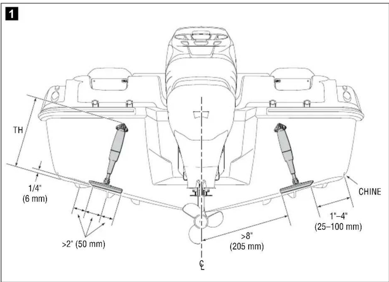
- There are different tab configurations available and they will have different transom height (TH) requirements as shown in figure 2. The actual transom height will vary with the angle of the transom, so the maximum value for TH is shown.
2
Dimensions shown apply to standard 11.5" actuator only.

STANDARD MOUNT

12" EDGE MOUNT — POCKET MOUNTED

12" EDGE MOUNT — TRANSOM MOUNTED
- There must be space behind the transom for the actuator harness to enter the boat in a dry location away from sources of heat.
3.2 Tab installation — standard and edge mount tabs
▶ Position the tab (fig 3 item 1) so that the hinge plate (fig 3 item 2) is approximately 1/4'' (6mm) up from the bottom of the hull and parallel to the hull. See also figure 1.
▶ If mounting in a pocket, center the tab in the pocket.
▶ Mark the hinge hole pattern on the transom as shown in figure 3.
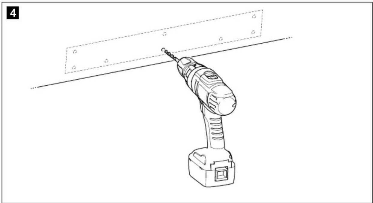
▶ Drill holes in the transom at the marked locations with a 3/16" (4.8 mm) drill bit to a depth of 1-1/4" (32 mm) as shown in figure 4.

natural_image
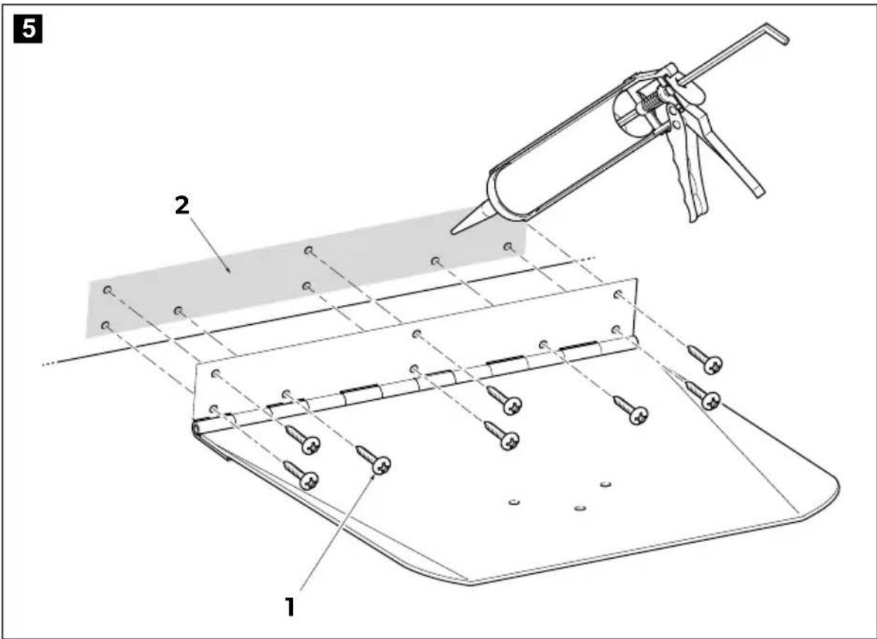
Line drawing of a power tool with a rectangular panel and screwdriver inserted, no text or symbols present▶ Liberally apply marine grade adhesive caulking (fig 5 item 2) at the interface between the hinge and transom, the drilled holes, and the supplied fasteners (fig 5 item 1) to ensure a watertight seal.
▶ Install the screws through the hinge plate and into the transom. The screws are designed to work in both fiberglass and aluminum hulls. We recommend tightening these screws by hand. Do not overtighten.

NOTICE! Potential damage to hull
Do not overtighten the screws, because you may strip the hull material.
3.3 Actuator installation — standard and edge mount tabs
The first step is to mark and drill the holes for the transom mounting bracket and the harness entry into the hull. You'll use the transom bracket itself, installed to the actuator, as your template.
Loosely assemble the transom bracket to the actuator as shown in figure 6. Insert the actuator mounting clevis into the bracket and install the pivot bolt in the bracket and loosely fasten the washer and nut. Do not route the harness through the bracket just yet.

natural_image
Technical line drawing of a mechanical clamp assembly with bolts and a connecting rod (no text or symbols)
▶ Ensure the actuator shaft (fig 7 item 9) is fully retracted by rotating it clockwise until travel stops. The shaft can safely be forced to continue rotating clockwise to align the mounting holes at each end of the actuator. The actuator should come in this position out of the box, so adjustment may not be necessary.
Insert the pivot bolt (fig 7 item 8) through the foot bracket and the actuator shaft. Install the washer and nut (fig 7 item 10 and item 4) and tighten to 30–40 in-lbs. Check that the actuator shaft pivots freely. A small amount of resistance to movement is acceptable, but it must not bind or require more than a few pounds of force to move. If necessary, loosen the nut slightly.
Install the foot bracket (fig 7 item 3) to the tab (fig 7 item 2) using the supplied screws (fig 7 item 1) and nuts (fig 7 item 5). Insert the screws from the bottom of the tab. Torque the foot bracket fasteners (fig 7 item 1 and item 5) to 60–70 in-lbs. in place of instruction to tighten until snug.

NOTE
If a 10" or 12" actuator is being installed, install screws into the threaded inserts in the foot brackets provided.

other
| TAB LENGTH | TRAILING EDGE HEIGHT (mm) | | ---------- | ------------------------- | | 0 | 1/4" (6.4 mm) | | 4" | 3/8" (9.5 mm) | | 9" | 1/2" (12.7 mm) | | 12" | 5/8" (15.9 mm) | | 14" | 3/4" (19.0 mm) | | 16" | 7/8" (22.2 mm) | | 18" | 1" (25.4 mm) |▶ Lift the tab into the running position as shown in figure 8. To ensure the tabs do not drag when retracted, they must be tilted up from the hull level. The longer the tab, the greater the height above the hull level at the trailing edge of the tab. You will need a long straight edge, such as a carpenter's level, and a helper for this step.
Once the tab angle is correct, position the transom bracket flush against the hull. Ensure that it lays naturally against the hull, with no force to the side.

NOTICE! Actuator wear
Misalignment will cause accelerated wear of the actuator.
▶ Trace the outline of the mounting bracket (fig 9 item 2) on the hull.
Remove the bracket from the actuator, line it up with the traced outline, and mark the mounting holes and the harness hole.
▶ Drill the mounting holes with a 3/16" (4.8 mm) drill bit to a depth of 1-1/4" (32 mm).
▶ Drill a 3/8" (9.5 mm) hole through the transom for the wiring harness.

NOTICE! Potential damage
Ensure there is nothing behind the hull that could be damaged by drilling the hole through the hull for the cable.
Now that the holes are drilled, you're ready to mount the actuator to the hull.
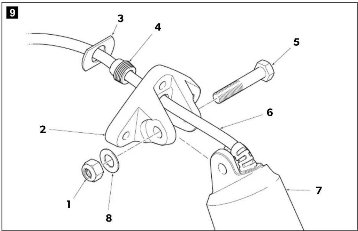
▶ Slide the mounting bracket (fig 9 item 2) over the actuator harness (fig 9 item 6) until you can mate it with the actuator (fig 9 item 7).
▶ Fit pivot bolt (fig 9 item 5) through the joint without installing the washer and nut (fig 9 item 8 and item 1).
▶ Grease the sealing grommet (fig 9 item 4) and slide it over the harness. Apply marine sealant to the sealing surface, then adjust it until it contacts the bracket.
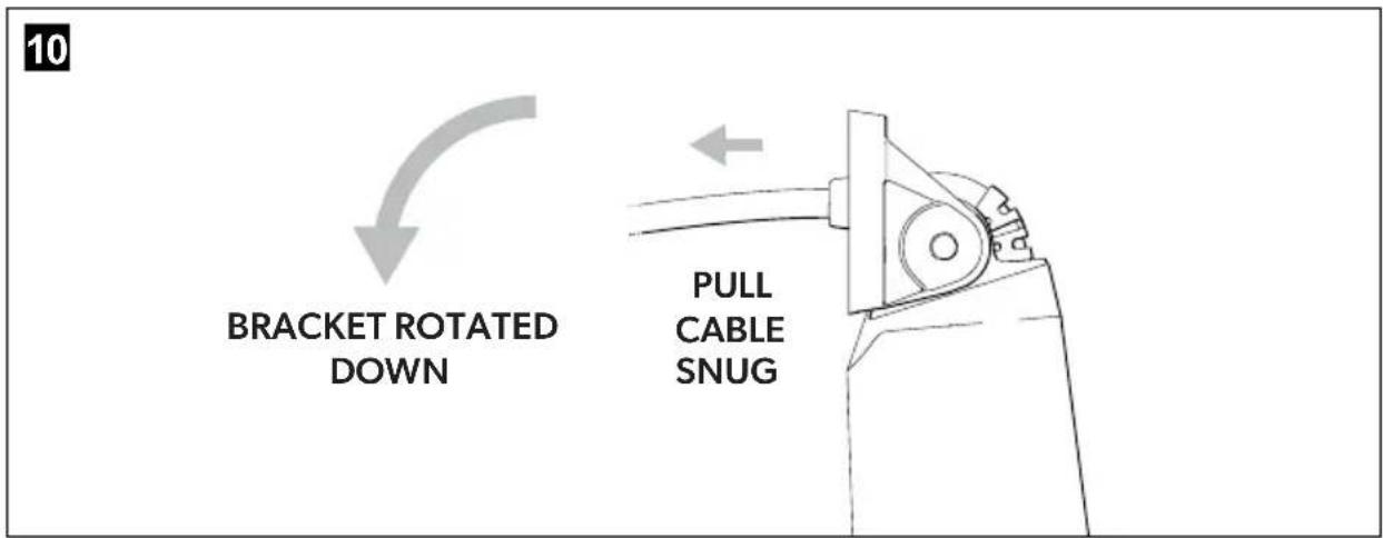
▶ While the sealant is still pliable, adjust the slack in the harness by pulling it snug with the bracket rotated down as shown in figure 10.
▶ Slide the harness compression plate (fig 9 item 3) over the harness until it fits in the recess in the rear of the bracket as shown in figure 11. Some sealant on the mating surfaces will help keep the compression plate in place during the following steps.

Insert the harness into the hole in the hull and feed it through until the actuator bracket is almost at the hull.
▶ Liberally apply marine grade sealant to the bracket, grommet, mounting holes and to the harness entry.
▶ Double check that there is a small amount of slack in the harness between the bracket and the entry into the actuator (fig 12 item 2). Mate the bracket to the hull, and install the 2 screws (fig 12 item 1). Do not over-tighten the screws.
This is done to ensure the center screw does not damage the actuator harness during installation.

When the bracket is fixed to the hull, remove the pivot bolt (fig 12 item 3) and lower the actuator to create clearance for the final screw, taking care not to pull the actuator harness out of the hull. Install the final screw, again taking care not to over-tighten. Reinstall pivot bolt, including the washer provided beneath the nut. Tighten nut to 30–40 in-lbs. Take care not to over-tighten.
4 Controller installation
The controller can be installed in a dash that is 1/4" to 1.5" thick and at any angle from horizontal to vertical. When determining where on the dash to place the trim tab controller, consider:
- are the buttons and indicator lights visible while operating the boat?
- is the dial accessible without interference from other dash components?
- is there enough clear space behind the dash? You will need at least 6" (155mm) from the surface of the dash to any obstructions behind it.
Once you've determined the controller location:
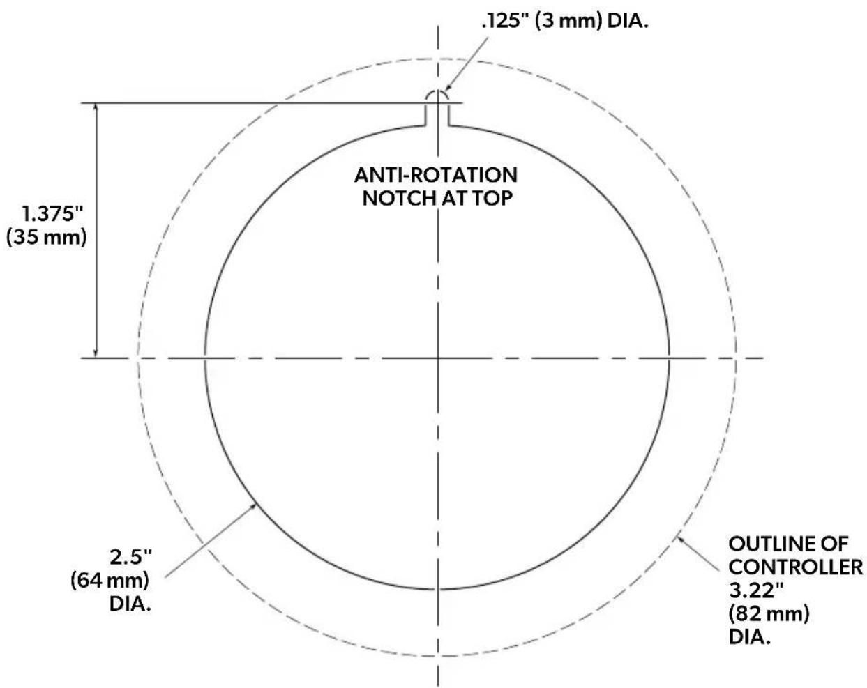
▶ Tape the template (section 8) to the dash and mark the center point of the controller and the anti-rotation notch. The notch must be at the top.
At the notch center point, drill a 1/8" diameter hole through the dash.
At the controller center, cut a circular hole through the dash with a 2.5" (64 mm) hole saw. Take care to cut perpendicularly to the dash.

NOTICE! Potential damage
Check that there are no wires behind the dash before drilling holes.
▶ Use a saw or file to remove any remaining material between the large hole and the small hole to create the notch.
Remove all rough edges and burrs from both front and rear surfaces of the dash.
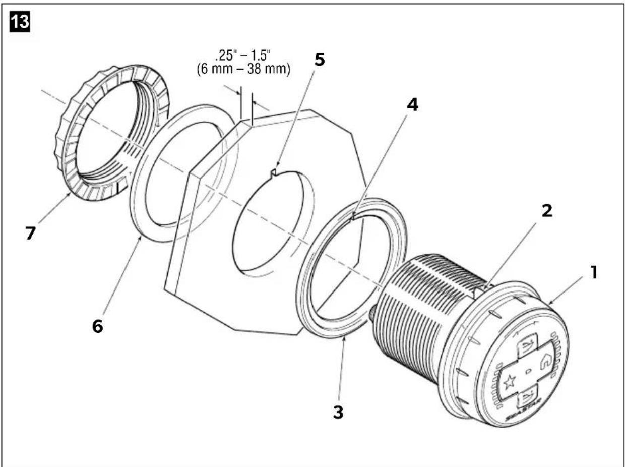
Remove the bezel nut (fig 13 item 7) and rear gasket (fig 13 item 6) from the controller (fig 13 item 1).
▶ Install the front gasket (fig 13 item 3) onto the controller with the notch (fig 13 item 4) aligned with the anti-rotation feature (fig 13 item 2) on the controller.
Install the controller in the dash opening (fig 13 item 5). Make any adjustments necessary so that the front gasket fits flush and smooth with the dash surface.
Place the rear gasket over the controller housing until it contacts the rear of the dash. Thread on the bezel nut and tighten securely by hand. Do not use a tool to tighten.

NOTE
If space is limited behind the dash, you may find it easier to connect the harness to the controller before installing it. See section 5 for harness information.
For installation of the controller into a location where pre-existing controller or rocker panel holes will still be visible, see "Trim Tab Cosmetic Controller Cover installation manual" (part # 682237).
5 System wiring
Planning the electrical installation is critical to a successful installation. Considering the electrical installation as a sequence of discrete steps can help organize your plan.
Section 5.1, Step 1 – Plan the installation
Section 5.2, Step 2 – Install the private CAN network
Section 5.3, Step 3 – Install connectors on actuator harnesses
Section 5.4, Step 4 – Connect devices to the private network
Section 5.5, Step 5 – Connect actuator power
Section 5.6, Step 6 – Connect to public network (optional)

NOTICE! This system is designed for use with 12VDC only.
It is not compatible with 24VDC. Connecting to 24VDC will damage the electrical components

WARNING!
All parts of the electrical installation must comply with relevant ABYC or ISO standards. Harnesses and wiring must be rated for 105°C and comply with the latest revisions of SAE J1128 or ISO 6722.
5.1 Step 1 — Plan the installation
The Adaptive Trim Tab system uses three distinct electrical sub-circuits:
-
a private CAN network to which the actuators and dial controllers are connected.
-
an individual power circuit for each actuator.
-
a public NMEA2000 network.
Each of these elements requires planning before you begin installation.
CAN network
Review section 5.2 and 5.4. Before you begin installation, you should:
- Know what the network schematic will look like. Sketch it out if there are any differences from the generic diagrams in this manual.
- Have all the required tees, harnesses, terminators, and mounting hardware.
- Know where you will mount the network tees.
- Know how you will route and secure the network harnesses.
- Know how you are powering the network and have the required parts.
Actuator power
Review section 5.5. Before you begin installation, you should:
- Know what power source you're using.
- Ensure the power source is suitable for the actuator power requirements.
- Have a plan to extend the power source to the stern of the boat if necessary.
- Have all the required circuit breakers/fuses, harnesses, and connecting wires.
Public NMEA2000 network
Connection to a public NMEA2000 network is required to get the following features on non-Optimus systems:
- Holeshot mode
• Automatic tab retraction in reverse gear
On both Optimus and non-Optimus systems you will need a public network connection if you want to display trim tab position on a multi-function display (MFD).
Review section 5.6. Before you begin installation, you should:
- Have the parts required to build a network or tie into an existing one.
- Know where the network power is coming from, if required.
- Have an NMEA2000 interface device for your engine (supplied by engine manufacturer).
5.2 Step 2 — Install the private CAN network
The CAN network used by the Adaptive Trim Tab system is private, meaning that only approved devices may be connected to it. Only components shown in this manual, or in the Optimus EPS installation manual, may be connected to the network.

WARNING!
Do not cut or splice network harnesses.
5.2.1 CAN network fundamentals
The generic network diagrams in this manual cannot represent every possible configuration and boat layout, so the network you build may look slightly different. It will help to understand the basics of CAN networks as you install your system.
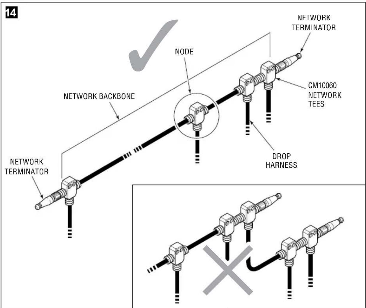
A CAN network is a communication bus with a trunk/drop topology as illustrated in figure 14.
- The trunk, or backbone, is formed by tees connected linearly, either directly to each other or with harnesses (table 5-1). Each tee has two backbone connectors (male and female), and a female drop connector.
- Drops are connections to devices on the network.
• Each connection point is called a node of the network. (Drop and node are often used interchangeably.) - The network is powered by a fused 12V supply, connected to the drop connector at a node. Low power devices (less than 1A) can be powered directly from the network.

Important things to consider when building a CAN network:
- Every network must have two – and only two – terminating resistors, one at each end of the backbone. One male and one female terminator are included in your installation kit.
- The backbone must be connected linearly. Do not branch the backbone at a node connector.
- Devices always connect to the drop connector. Do not connect to the backbone connector.
- Do not cap unconnected nodes with a terminating resistor. Either remove the node or install a sealing cap.
- Consider the length of the drop harnesses when mounting the tees. It is preferable to build the network backbone so that the tee is within reach rather than extending the harness.
- Do not use tools to tighten the connectors. Hand-tighten only.
All kits include harnesses for each component in your system. If you need longer harnesses, you can order extensions from table 5-1.
| Micro-C DevicNet harness | ||
| Description Length, ft (m) Part No. | ||
| Micro C Extension, Male/Female 1 (0.3) CM10001 | ||
| 3 (0.9) CM10003 | ||
| 6 (1.8) CM10006 | ||
| 9 (2.7) CM10009 | ||
| 12 (3.6) CM10012 | ||
| 16 (4.9) CM10016 | ||
| 20 (6.1) CM10020 | ||
| 30 (9.1) CM10030 | ||
Table 5-1.
5.2.2 CAN tee installation
▶ Install tees in a dry location.
▶ Secure the tees and harnesses as shown in figure 14.
▶ Mark the connections with a felt marker. This will make loose connections visible.

5.2.3 Network installation — Adaptive Trim Tab

NOTE
If the boat is equipped with Optimus EPS, skip to section 5.2.4.
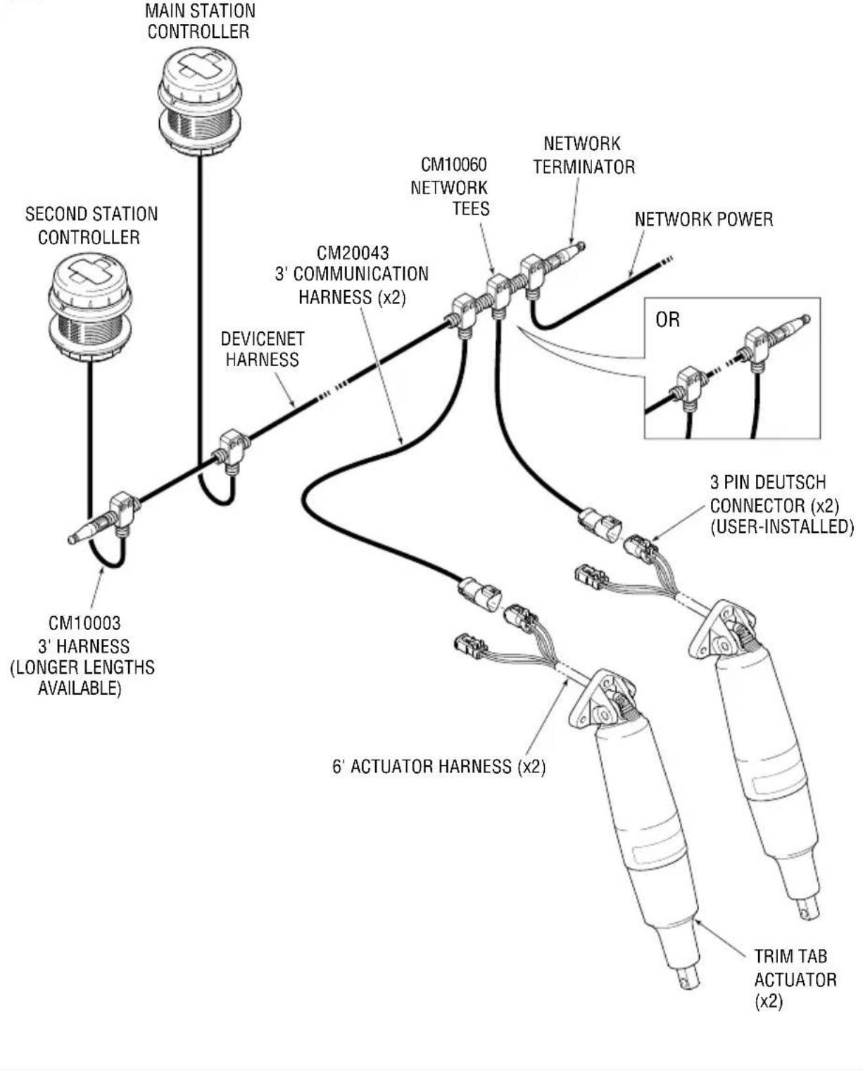
The CAN network is shown in figure 15 (single controller) and figure 16 (dual controller).
Installation notes:
- Your kit will include device tees, terminating resistors, and a power drop tee, but the backbone harness(es) must be ordered separately (table 5-1).
- The combined length of the actuator and communication harness is 9' (2.7m). The actuator tees must be within reach of the properly routed, protected, and secured harness. You may be able to mount the actuator drop tees together, or it may be better to mount them closer to the sides of the boat with a backbone harness joining them.
- The location of the actuator power source (section 5.5) may affect the reach of the communication harness.
Installation:
▶ Mount a tee for each actuator and controller in your system.
▶ Review the requirements for the network power (page 21) and determine the best location for the network power tee. It may not be as shown in the diagrams.
Connect the tees with harnesses to build the CAN network backbone. Route the harness(es) so they are dry, away from sources of heat, and properly secured.
▶ Install one network terminator at each end of the backbone.
▶ Connect the devices to the network (section 5.4).

flowchart
graph TD
    A["CONTROLLER"] --> B["CM10003 3' HARNESS (LONGER LENGTHS AVAILABLE)"]
    B --> C["DEVICENET HARNESS"]
    C --> D["CM20043 3' COMMUNICATION HARNESS (x2)"]
    D --> E["CM10060 NETWORK TEES"]
    E --> F["NETWORK TERMINATOR"]
    F --> G["NETWORK POWER"]
    G --> H["OR"]
    H --> I["3 PIN DEUTSCH CONNECTOR (x2) (USER-INSTALLED)"]
    I --> J["6' ACTUATOR HARNESS (x2)"]
    J --> K["TRIM TAB ACTUATOR (x2)"]
17
Network power connection

NOTE
If the boat is equipped with Optimus EPS the control power will come from the CAN2 network and you may ignore this section.
Network power turns the trim tab system on and off. The dial controller is powered directly from the network, and the actuators receive a wake-up signal when the network is powered on.
The network is powered from a 12V source with the power drop tee (P/N CM21403) supplied with your installation kit. You must wire a fuse (3A, not supplied) into the circuit as shown in the diagrams.
It is important that the power supply is one that cannot be left on while the boat is not in use. The dial controllers will draw a small amount of current continuously and could drain a battery if left on. Some connection options are shown here.
Option 1 — Engine ignition (preferred)
To turn the trim tab system on and off with the engine ignition, switch the source through the engine ignition switch as shown in figure 18. If there is more than one ignition switch you will need one or more Dual Ignition Kits (HA1201) to ensure that the trim tab system is powered when any of the engines are running. The number of kits you will require is one less than the number of ignition switches. The kit includes wiring diagrams.
18

Option 2 — Accessory bus
If you have a 12V accessory bus that is switched on with a master control relay, accessory power switch, or battery switch, you can connect the power drop to it as illustrated in figure 18.

NOTE
If the accessory bus does not switch off with engine ignition you will lose the automatic tab retraction on ignition-off feature.
19

5.2.4 Network installation — Optimus Adaptive Trim Tab

NOTE
This section is for boats equipped with an Optimus EPS system.
For other installations go to section 5.2.3.
The Optimus Adaptive Trim Tab system uses the existing Optimus EPS CAN2 network as shown in figure 19 (single controller) and figure 20 (dual controller). It isn't possible to show every possible configuration that the combined network can take, so these figures omit the Optimus EPS components.
Installation notes:
- Your kit will include device tees, but if you need additional backbone harness(es) they must be ordered separately (table 5-1).
- The combined length of the actuator and communication harness is 9' (2.7m). The actuator tees must be within reach of the properly routed, protected, and secured harness. You may be able to mount the actuator drop tees together, or it may be better to mount them closer to the sides of the boat with a backbone harness joining them.
- The location of the actuator power source (section 5.5) may affect the reach of the communication harness.
- The CAN2 network is already powered, so no additional power connection is required.
Installation:
▶ Mount a tee for each actuator and controller in your system.
▶ Run harnesses as required to connect the tees to the CAN2 network backbone. Route the harness(es) so they are dry, away from sources of heat, and properly secured.
▶ Check that there is one network terminator at each end of the backbone.
▶ Connect the devices to the network (section 5.4).
20
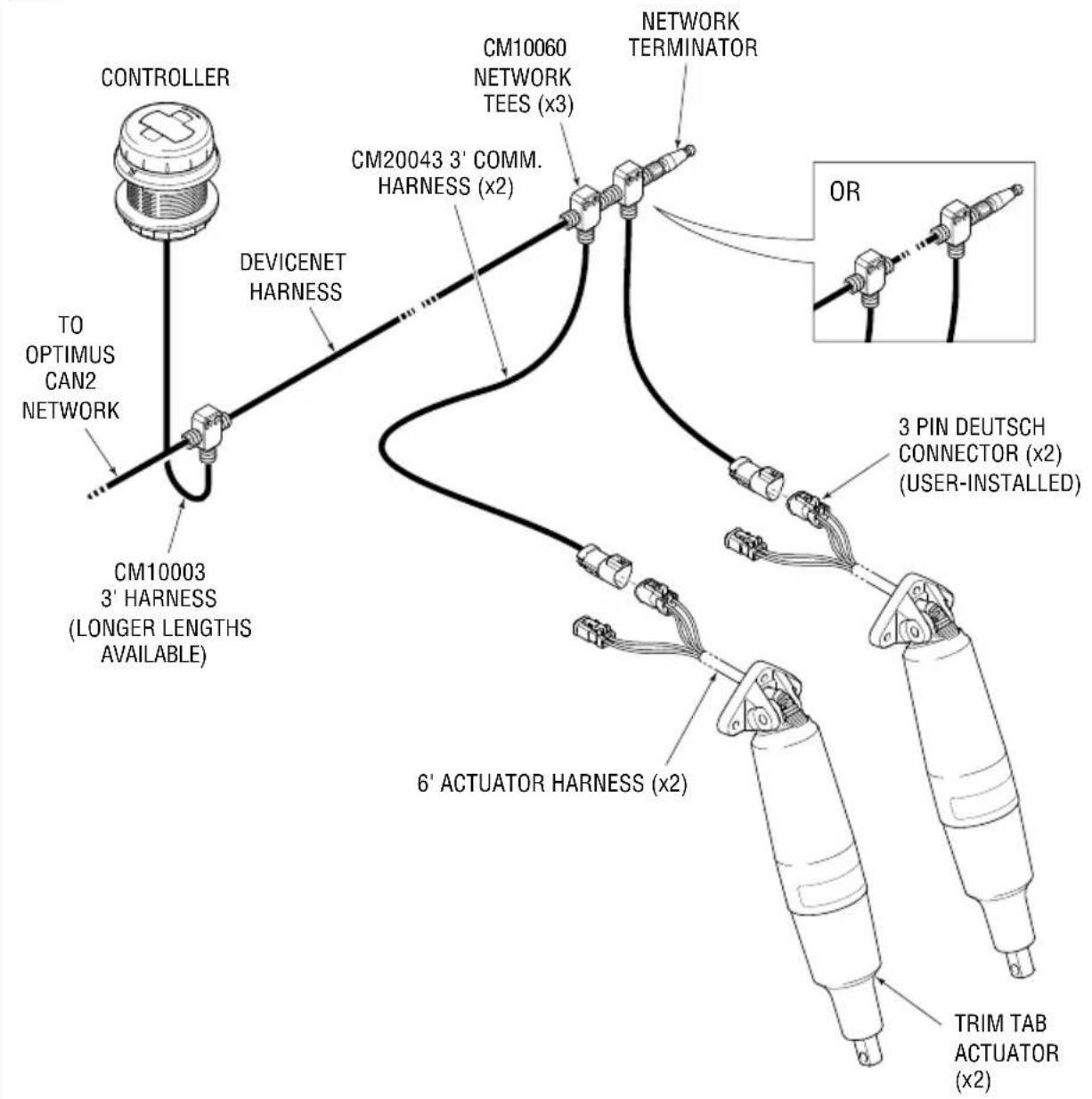
flowchart
graph TD
    A["CONTROLLER"] --> B["TO OPTIMUS CAN2 NETWORK"]
    B --> C["CM10003 3' HARNESS (LONGER LENGTHS AVAILABLE)"]
    C --> D["DEVICENET HARNESS"]
    D --> E["CM20043 3' COMM. HARNESS (x2)"]
    E --> F["CM10060 NETWORK TEES (x3)"]
    F --> G["NETWORK TERMINATOR"]
    G --> H["OR"]
    H --> I["3 PIN DEUTSCH CONNECTOR (x2) (USER-INSTALLED)"]
    I --> J["6' ACTUATOR HARNESS (x2)"]
    J --> K["TRIM TAB ACTUATOR (x2)"]
21
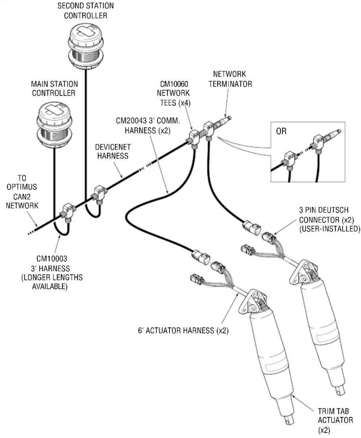
flowchart
graph TD
    A["SECOND STATION CONTROLLER"] --> B["MAIN STATION CONTROLLER"]
    B --> C["TO OPTIMUS CAN2 NETWORK"]
    C --> D["CM10003 3' HARNESS (LONGER LENGTHS AVAILABLE)"]
    D --> E["DEVICENET HARNESS"]
    E --> F["CM20043 3' COMM. HARNESS (x2)"]
    F --> G["Network TERMINATOR"]
    G --> H["OR"]
    H --> I["3 PIN DEUTSCH CONNECTOR (x2) (USER-INSTALLED)"]
    I --> J["6' ACTUATOR HARNESS (x2)"]
    J --> K["TRIM TAB ACTUATOR (x2)"]
5.3 Step 3 — Install connectors on actuator harnesses
The actuators come with a 6' (1.8m) harness containing the five conductors listed in table 5-2. The conductors are fitted with crimped terminals, but the connectors must be installed after the harness has been routed into the boat and sealed. These connectors will mate with the power and communication harnesses that come with the actuator kit.
To install the connectors:
▶ Refer to table 5-2 to determine the wire pinouts.
| Wire Color | Function | Connector | Pin ID (molded into connector) |
| White CAN High J1 - 3 pin A | |||
| Blue CAN Low J1 - 3 pin B | |||
| Purple Wake-up J1 - 3 pin C | |||
| Red | 12V Battery +ve | J2 - 2 pin 1 | |
| Black | 12V Battery -ve | J2 - 2 pin | 2 |
Table 5-2.
▶ Grip the wire just behind the crimped contact barrel and hold the connector with the grommet facing you.
▶ Push the contact straight into the grommet until you feel a positive stop.
▶ You will hear a click and the contact will lock into place. A tug on the wire will confirm that it is properly secured
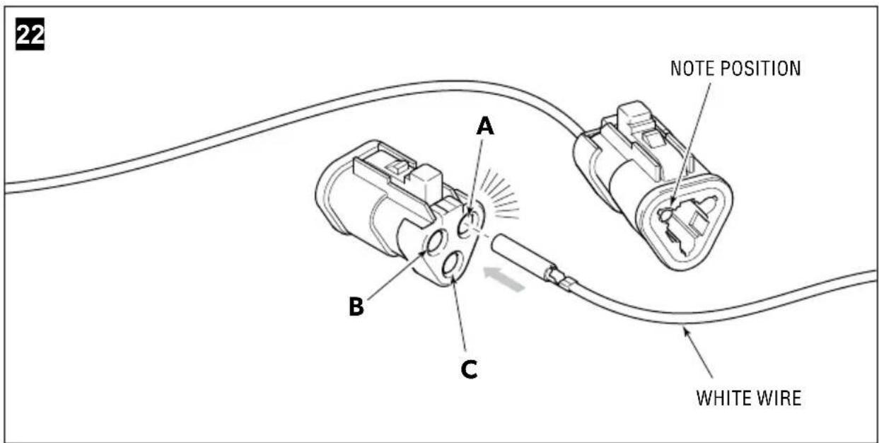
▶ Repeat for all the contacts in the connector.
When all the contacts are inserted, install the locking wedge from the pin side. Press it in firmly until you hear a click

natural_image
Diagram of two electrical connectors with wires, one being held by a finger (no text or symbols present)If the wire needs to be removed:
Remove the wedge lock.

natural_image
Technical line drawing of a mechanical component with wires and a screwdriver (no text or symbols)Gently pry on the inner lock tab and then pull the wire out the back (wire side) of the connector until the terminal and wire is removed from the connector. Ensure all open cavities are plugged.
5.4 Step 4 — Connect devices to the private network
5.4.1 Dial controller
The dial controller has two connectors on the back, labeled 'CAN2' and 'N2K.' The N2K port is shipped with a sealing cap; leave it in place unless you are connecting to a public network (section 5.6).
For each dial controller:
Connect the female end of the supplied harness (CM10003) to the port labeled 'CAN2.'
▶ Connect the male end of the harness to the network tee. (Use an extension harness from table 5-1 if the harness is not long enough.)
▶ Secure the harness at both ends for strain relief.
▶ Coil up any slack in the harness and secure it.
25

5.4.2 Adaptive actuator
The communication harness (CM20043) has a 3-pin triangular connector at one end and a round connector at the other end. For each actuator:
Plug the communication harness into the mating connector on the actuator harness until the lock engages. (section 5.3).
▶ Connect the round connector to a network tee.
▶ Secure the communication harness at both ends to relieve strain on the connectors.
▶ Coil and secure any slack in the actuator harness.
5.5 Step 5 - Connect actuator power
The actuators connect to a 12VDC power source using the 3' (.9m) power harness (CM20044) supplied with your kit. The source may be the engine battery terminals, a battery switch, a panelboard, or a busbar. The combined length of the actuator and power harness is 9' (2.7m), so the power source must be aft and within reach of the harness. If you do not have a power source within reach, refer to section 5.5.1.
In operation each trim tab actuator will draw 10–15A, with momentary peaks up to 20A. Each actuator must be protected with a dedicated fuse or breaker. It is important that power supply wires are correctly sized for the load according to ABYC or ISO requirements.

WARNING!
Each trim tab actuator requires its own circuit protection device. Use only fuses or circuit breakers designed for marine use.

WARNING!
Panelboards or busbars must be supplied with a conductor and circuit protection device appropriately sized for all loads that may be connected to it.
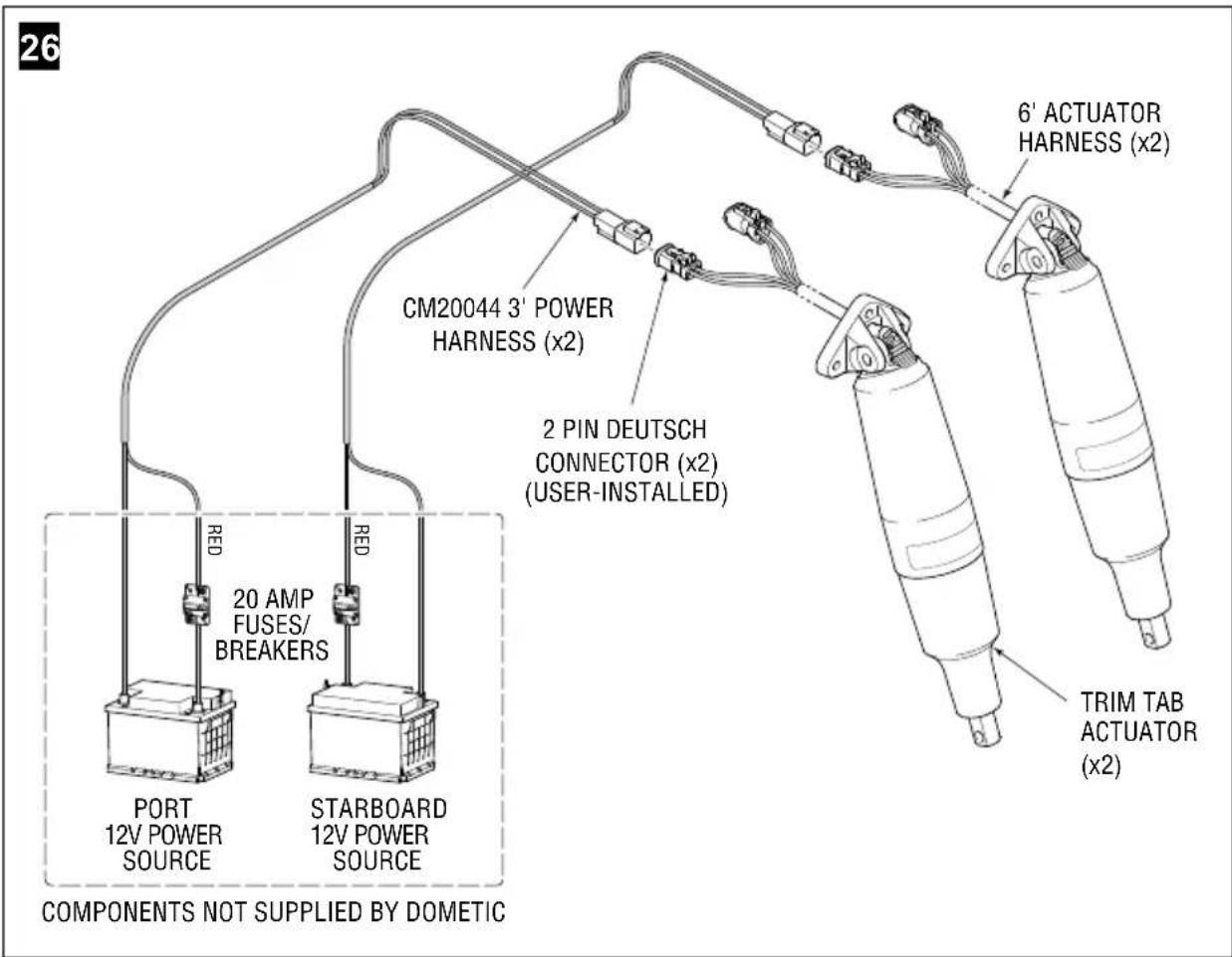
Connect the port and starboard actuators to separate port and starboard power sources. Exception: on a single engine boat you may connect both actuators to the main power source.

For each trim tab actuator:
Install a 20A fuse or circuit breaker within 7" (200 mm where ISO applies) of the power source as required by ABYC standards. Use minimum 14AWG wire (12AWG is preferred).
▶ Connect the red wire of the power harness to the fuse/breaker and the black wire to the battery negative terminal or negative bus.
▶ Plug the power harness into the actuator harness until the locking tab engages.
▶ Properly secure and strain-relieve the harnesses.
Figure 25 and figure 26 show these connections for standard tabs and heavy-duty tabs (two actuators per tab) respectively.
5.5.1 No power source aft
If there is no DC power source of suitable capacity in the stern you will need to create one. We recommend you use an insulated stud terminal connector (such as Blue Sea PowerPost or similar) for this purpose. One possibility is illustrated in figure 27 and described below.
For each trim tab actuator:
▶ Install an insulated stud connector within reach of the actuator power harness.
Install a 20A fuse or circuit breaker within 7" (200 mm where ISO applies) of an available power source as required by ABYC standards. Use wire size shown in table 5-3.
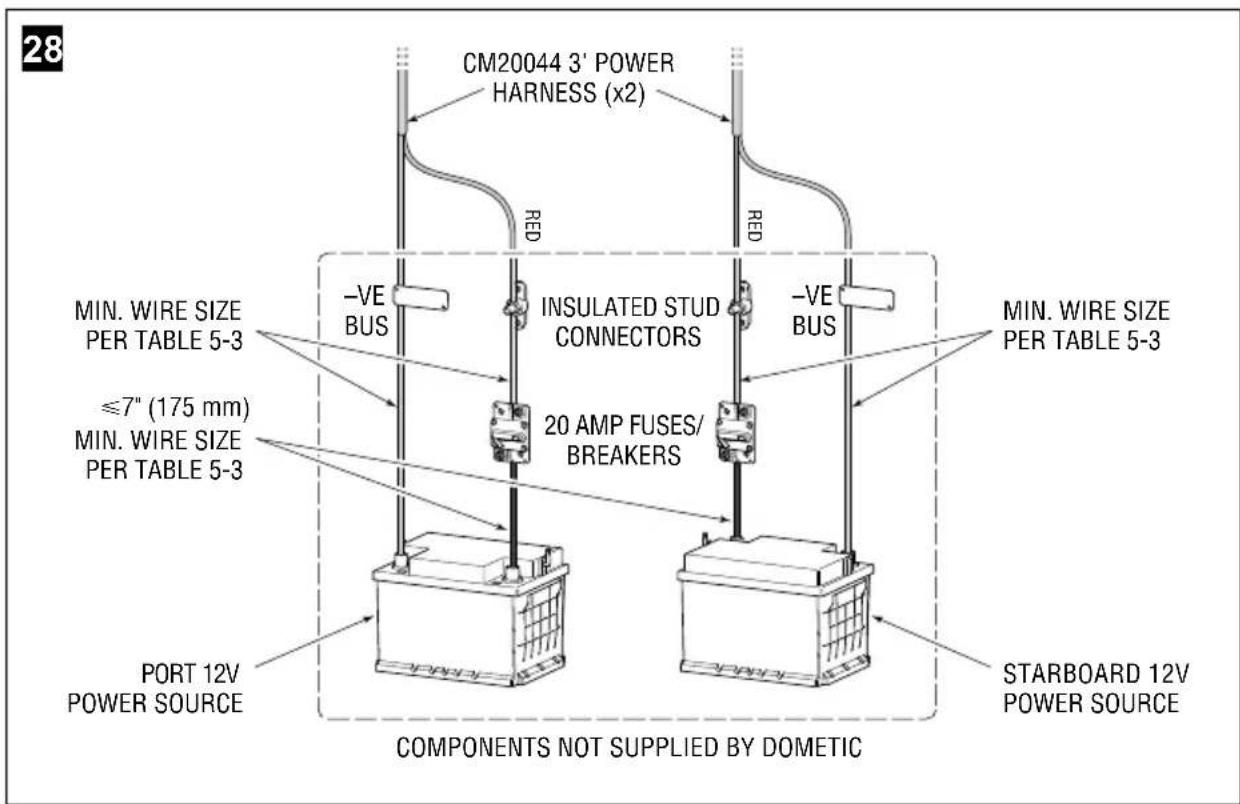
▶ Use red wire of the size shown in table 5-3 to connect the breaker to the insulated stud connector. Take care to route and secure the wire properly.
If there is no negative bus aft, install one and connect to the battery -ve with black or yellow wire of the size shown in table 5-3.
▶ Connect the actuator harness as described in the previous section.
| Total length of wire from power source to power harness connection and back to source | Recommended wire size AWG (mm2)* |
| < 18' (5.5m) 12 (4.0) | |
| < 48' (14.6m) 10 (6.0) | |
| < 78' (23.8m) 8 (10) | |
| < 138' (42m) 6 (16) |
Table 5-3. *Based on 10% voltage drop per ABYC E-11.
5.6 Step 6 — Connect public network
The Adaptive Trim Tab system reads engine RPM and gear position from this network and broadcasts the trim tab positions for display on MFDs. In a multi-station boat, only the main controller should be connected to a public network.

Boat has a NMEA2000-compliant network
▶ Add a tee to the existing public network.
Remove the sealing cap from the port marked 'N2K' on the main station dial controller.
▶ Use a harness (table 5-1) to connect the dial controller N2K port to the tee.
▶ Secure the harness at both ends for strain relief.
▶ Coil up any slack in the harness and secure it.
Boat does not have a NMEA2000-compliant network

NOTE
It is not mandatory that you install a NMEA2000 network, but it is required to get the full functionality of the Adaptive Trim Tab system.
You will need kit CM20003. It includes everything you need to build the small network shown in figure 28:
▶ Assemble the power drop tee to the multi-port tee and install the assembly close to the main station dial controller. Install the terminating resistors.
▶ Wire the power drop tee to a 3A fused 12V power source (see figure 18 for a sample power connection).
▶ Connect an engine gateway to one of the open nodes.
Remove the sealing cap from the port marked 'N2K' on the main station dial controller.
▶ Use a harness (table 5-1) to connect the dial controller N2K port to the other open node.
▶ Secure all the harnesses at both ends for strain relief. Ensure they are all routed neatly and securely, with any slack coiled up.
6 Setup
The Adaptive Trim Tab System needs to be configured before use. Setup is done with a CANtrak display (section 6.1) or the dial controller (section 6.2).
6.1 Setup with display

NOTE
If the boat is not equipped with a CANtrak display, you will need to add a temporary tee to the CAN network and connect a display tool to it. You will need software version SW0292RevAA or higher on the display.
6.1.1 Basic setup
The system will detect the number of devices on the network, but they need to be instanced. That is, you must tell the system which actuator(s) are port, which are starboard, and which dial controller is main.
From the dealer menu:
▶ Go to Initial Setup > System > Select Device Locations.
√ Actuators and dial controllers will be displayed with their serial numbers and assigned an instance by default.
Record the device serial numbers. The serial numbers are 12-digit alphanumeric strings, found on the back of the controller (starting "TTC") and on the end of the actuator harness (starting "TTA").
▶ Match the serial number for each actuator and controller and use the + and - buttons to adjust the instance location as required.

6.1.2 Stroke limit
In some applications you may need to limit the stroke of the actuators. The system provides several stroke lengths that can be configured, as shown in the table. Note that the stroke length affects extension, not retraction. The actuators will always retract to the home position—you can't limit the retraction stroke.
From the dealer menu:
▶ Go to Initial Setup > Adaptive Dial Controller > Control.
Use the + and - buttons to change the Tab Actuator Stroke Limit Level parameter value if necessary.
| Stroke limit level 1 2 3 | 4 5 | ||||
| Short actuator (2.25") | 1.0" | 1.5" | 1.75" | 2.0" | 2.25" (full) |
| Long actuator (4.25") | 2.5" | 3.5" | 4.0" | 4.25" (full) | N/A |
Table 6-1.
Example: A short actuator (2.25" standard stroke) with stroke limit level set to 3 will have an operating stroke of 1.75" from fully retracted.
6.1.3 Additional setup
There are additional parameters, listed in section 6.3 and 6.4, that are used to tune trim tab performance. Most of these will be set during the testing and commissioning phase of the installation (section 7).
6.2 Setup with dial controller
The function of the dial controller during setup is illustrated below.
30
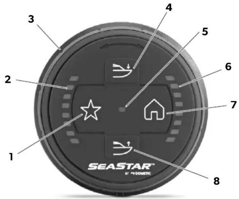
| No. in figure | Name in this section | Function |
| 1 | Favorite Saves the parameter and advances to the next step. | |
| 2 | Port LEDs | Indicates the setup step, from 0 (no LEDs) to 8 (all LEDs). |
| 3 | Dial Clockwise rotation increases the parameter, counterclockwise decreases it. | |
| 4, 8 | Bow Down Bow Up | Enters setup mode when pressed and held together for five seconds. |
| 5 | Status LED | Indicates mode. Alternates blue and magenta when in setup mode. |
| 6 | Stbd LEDs Indicates the parameter value. | |
| 7 | Home Exits setup mode without saving current parameter. | |
Table 6-2.
To enter setup mode:
▶ Key on the ignition.
▶ Simultaneously press and hold the Bow Down and Bow Up buttons for five seconds.
√ The status LED will alternate blue and magenta.
√ The port LEDs are all off, indicating that you are in step 0.
6.2.1 Step 0 — Actuator and controller instancing
The system will detect the number of devices on the network, but they need to be instanced. That is, you must tell the system which actuator(s) are port, which are starboard, and which dial controller is main. The controller you use for setup is automatically instanced as the main controller, so you only need to instance the actuators manually.
When you enter Step 0 the controller LEDs will illuminate as shown. If you haven't yet instanced the actuators the LEDs representing them will flash. When properly instanced they illuminate solid. If only the top LED is flashing, there is an error in one of the instances and you should repeat the instancing procedure.
31

To instance the actuators:
▶ Unplug the starboard actuator at the three-pin communication harness (figure 32). In an HD system with two actuators you must unplug both actuators.
▶ Plug the actuator(s) back in.
√ The stbd LEDs will stop flashing and become solid.

natural_image
Illustration of a hand holding a cable with connector pins, no text or symbols present√ The actuator(s) you unplugged are instanced as starboard. The actuator(s) that remained plugged in are instanced as port.
√ On HD installations with two actuators per tab, the lower serial number will be instanced as main, the other will be second.
▶ Press the Favorite button to save and continue to Step 1.
√ One port LED illuminates to indicate you are in Step 1.
6.2.2 Step 1-8
Most of these parameters will be set during the testing and commissioning phase of the installation (section 7).
Table 6-3 lists the parameter for each step of the setup and the parameter value corresponding to the number of stbd LEDs that are illuminated. It also lists the parameter units and tells you where you can find a detailed parameter description.
For each step:
▶ Rotate the dial to increase or decrease the parameter to the desired value.
▶ Press Favorite to save the parameter and move to the next step.
Press Home to exit when setup is finished, or if you need to exit before completion. The current parameter will not be saved, but previously saved parameters are not affected.

NOTE
When configuring SOG and RPM parameters, if the actual SOG or RPM is between the available values select the higher value. For example, if actual Planing Boat RPM is 3500, select 3700.
Table 6-3. * see section 6.2.3.
| Step Parameter no. name | See for parameter description | Units | Number of starboard LEDs illuminated | |||||||
| 1 Pitch and roll sensitivity | Table 6-5 - Least | Sensitive Default | ||||||||
| 2 Stroke limit (short actuator) | Sec 6.1.2 | Inch | 1.0 | 1.5 | 1.75 | 2.0 | 2.25 (full) | n/a | n/a | n/a |
| 3 Planning boat SOC* (long actuator) | Sec 6.1.2 | Inch | 2.5 | 3.5 | 4.0 | 4.25 (full) | n/a | n/a | n/a | n/a |
| 4 Planing boat RPM | Table 6-4 | RPM | 2300 | 2600 | 2800 | 3000 | 3200 | 3400 | 3700 | 4000 |
| 5 Deputy position | Table 6-4 | % of Max. | 60 | 70 | 75 | 80 | 85 | 95 | 100 | |
| 6 Deputy hold duration | Table 6-4 | Seconds | 1.5 | 2.0 | 2.5 | 3.0 | 3.5 | 4.0 | 5.0 | 6.0 |
| 7 Retract to favorable speed | Table 6-4 | Seconds | 2.0 | 2.5 | 3.0 | 3.5 | 4.0 | 4.5 | 5.5 | 6.0 |
| 8 Min deploy RPM | Table 6-4 | RPM | 1400 | 1600 | 1800 | 2000 | 2400 | 2600 | 2800 | 3000 |

The parameter values available in this setup procedure will work for most boats. In some rare cases you may get
improved performance with finer parameter increments, in which case you will need to use a CA/tract display.
NOTE
6.2.3 Planing boat SOG
If the boat does not have a speed-over-ground (SOG) source, or you need to disable it for any reason:
In setup mode, step 3, rotate the dial counterclockwise until no starboard LEDs are illuminated.
√ SOG is disabled.
▶ Press Favorite to save.
Notes on SOG source:
- In an Optimus Adaptive system, if the boat has the GPS sensor that comes with SeaStation it will have an SOG source.
- When connected to a public NMEA2000 network (section 5.6) the system can use any SOG source available on the network. Typical sources include chart plotters and/or autopilots with internal or external GPS.
- The public network may have several SOG sources. The system will take the first source it finds with a valid signal and latch to it. If the signal becomes invalid, the system will repeat the search for a valid signal and latch to the next one it finds.
6.3 Holeshot Mode parameters
Holeshot Mode is a semi-automatic mode designed to get a boat up on plane quickly without having to manually operate the trim tabs. When enabled (see table 6-5), and when activated by the operator, the controller will automatically deploy and retract the tabs when getting up on plane.
The controller uses engine RPM and, if available, speed-over-ground (SOG) to detect a holeshot and trigger tab deployment and retraction. Best performance is achieved with an SOG source, as speed is more directly related to planing than RPM. See section 6.2.3 for more information on SOG sources.
Holeshot Mode uses several parameters to control how it works, split into two groups: Initial Setup parameters and Settings parameters.
- Initial Setup parameters should be tuned during a sea trial. See section 7.1. Once you have the parameters set you can record them for use with future boats of the same hull, tab, and engine configuration. The parameters are saved along with the Optimus steering parameters, so you can import an entire configuration file into identical boat builds.
- Settings parameters are advanced parameters. The default settings should work for most boats. You should not need to change them unless advised by a Dometic technical services representative.
| Parameter Default Value Description | ||
| Initial setup parameters, found at:Dealer Menu > Initial Setup > Adaptive Dial Controller > Holeshot | ||
| Planing Boat Speed | 22 mph The minimum speed-over-ground (SOG) at which the boat gets on plane under slow acceleration. This parameter is only used if a SOG source is available and the SOG feature is enabled (table 6-5). | |
| Min Boat Planing RPM | 3000 rpm The lowest engine RPM at which the boat gets on plane under slow acceleration with all engines deployed and trimmed in their normal running position. | |
| Deploy Position | 100% The position of the tabs when deployed for a hole-shot, where 0% is fully retracted and 100% is fully extended. | |
| Deploy Hold Duration | 3.0 sec The time that the deploy position is held before tabs begin to retract. This parameter is not used if an SOG source is available and the SOG feature is enabled (table 6-5). | |
| Retract to Favorite Speed | 3.0 sec The time it takes to go from the holeshot deployed position to the adaptive cruising favorite position. | |
| Min Deploy RPM | 2000 rpm The RPM that triggers tab deployment when Holeshot Mode is activated. | |
| Settings parameters, found at:Dealer Menu > Settings > Adaptive Dial Controller > Holeshot | ||
| Planing Time Limit | 15.0 sec The user has this amount of time to initiate a holeshot once Holeshot Mode is activated. If the time expires, Holeshot Mode will be deactivated and the tabs will retract to the adaptive cruising favorite position. This parameter is not used if an SOG source is available and the SOG feature is enabled (table 6-5). | |
Table 6-4.
6.3 Control and Options parameters
There are parameters for trim control as well as optional feature settings.
| Parameter Default Value Description | ||
| These parameters are found at:Dealer Menu > Settings > Adaptive Dial Controller > Control | ||
| Pitch Control Sensitivity Level | 4 Controls the magnitude and speed of pitch adjustments (bow up/down). The higher the number, the more sensitive the adjustments (more change for each push of the button). The range is 1-7. | |
| Roll Control Sensitivity Level | 4 Controls the magnitude and speed of roll adjustments (dial control). The higher the number, the more sensitive the adjustments (more change for click of dial rotation). The range is 1-7. | |
| These parameters are found at:Dealer Menu > Settings > Trim Dial > Options | ||
| Enable Reverse Gear Integration | Yes When enabled, the trim tabs will retract when engine(s) shift into reverse gear. | |
| Enable SOG Feature | Yes When enabled, the trim tab system will use an available speed-over-ground (SOG) signal to improve holeshot performance. | |
| Enable Joystick Integration | Yes When enabled, the trim tabs will retract when the joystick is activated. Requires Optimus 360 Joystick control system. | |
| Enable Holeshot Functionality | Yes Controls the function of the Favorite button. When set to 'Yes' the Favorite button activates Holeshot mode. When 'No' the Favorite button sets or recalls a Favorite position. This parameter can be toggled from the dial controller by pressing the Favorite and Bow Up buttons together for three seconds. The status LED will flash magenta when Holeshot mode is enabled, green when Favorite position is enabled. | |
Table 6-5.
7 Testing and commissioning
Once the system has been installed, and the sealant used on all hull penetrations has had time to fully cure (refer to the sealant manufacturer's instructions), sea trial the boat to test the trim tab functions and to make any required adjustments to the system parameters.
Refer to the Operating Manual for operating instructions, including activation and use of Holeshot Mode. If you have chosen not to enable Holeshot Mode in the dealer menu, be sure to test the Favorite Position function during sea trial.
7.1 System tuning
The performance of holeshot mode is sensitive to system tuning, and for best performance the system should be tuned in a sea trial. The parameters that will most affect performance are the initial setup parameters (table 6-4).

WARNING!
Proceed carefully to deep, open water to conduct sea trials. Wear a PFD and connect the engine lanyard(s) to the operator.
Setting the Adaptive Cruising Favorite position for the first time
Before you begin tuning the system for the first time you need to set the favorite position.
With holeshot mode enabled (table 6-5), spend some time up on plane and manually trim the tabs using the Bow Up and Bow Down buttons to find a good running trim. Once you are satisfied with the trim, push the Holeshot Mode/Favorite button.
√ The center LED will light up steady magenta if a valid SOG source is latched (section 6.2.3), or lime green otherwise.
▶ Hold the trim position for twenty seconds.
√ The center LED will flash cyan rapidly for 2 seconds to indicate that the Adaptive Cruising Favorite position has been learned for the boat.
The controller will monitor and auto-learn the Adaptive Cruising Favorite position whenever it is adjusted while holeshot mode is activated.
Tune the initial setup parameters in order:
1. Min Boat Planing RPM
▶ Press the Home button to retract the trim tabs.
▶ Trim the engines to a normal running position.
▶ Shift into forward gear and slowly increase throttle until the boat gets on plane. Note the engine RPM when the boat gets on plane and enter it in this parameter.
2. Planing Boat Speed
▶ Note the speed at which the boat gets on plane and enter it in this parameter.
3. Deploy Position
▶ Activate Holeshot Mode and throttle up as you normally would when taking the boat up on plane.
The trim tabs will deploy to the Deploy Position as the boat accelerates.
Notice the boat's attitude as it gets up on plane. If there is excessive bow rise, increase the parameter value. If there is excessive bow steer, or the bow is digging in, decrease the parameter value.
▶ Make small changes to the parameter and test after each change.
4. Deploy Hold Duration
If the boat has an SOG source, you can skip this step, as this parameter is not used.
▶ Activate Holeshot Mode and throttle up as you normally would when taking the boat up on plane.
√ The trim tabs will extend to their deploy position then begin to retract after the number of seconds in this parameter has elapsed.
Once the trim tabs have deployed, notice the way the boat's attitude changes as it gets up on plane. If there is excessive bow rise, decrease the parameter value. If there is excessive bow steer, or the bow is digging in, increase the parameter value.
▶ Make small changes to the parameter and test after each change.
5. Retract to Favorite Speed
This parameter has a less noticeable effect than Deploy Position and Deploy Hold Time, but if there is still excessive bow rise after tuning those parameters you can increase the value of this parameter.
▶ Activate Holeshot Mode.
With the parameter at its default value, throttle up as you normally would when taking the boat up on plane. Observe the performance.
▶ Increase the parameter and repeat getting up on plane until you are satisfied with the amount of bow rise.
7.2 Faults and troubleshooting
7.2.1 Fault types
Non-critical faults
A flashing yellow status LED indicates a fault that does not affect the actuators.
An example is a faulty dial sensor. The trim tabs would still be operable using the bow up and bow down buttons, but the dial would not work.
Critical faults
A flashing red status LED indicates a critical fault that will prevent one or both actuators from operating.
Conditions that can cause a critical fault include:
- low or high battery voltage (these will reset automatically if the voltage condition is corrected).
Actuator faults
A flashing tab position LED indicates an actuator fault. The LED corresponding to the last known position will flash.
Conditions that can cause an actuator fault include:
- an actuator harness is unplugged, corroded, or otherwise not making a connection.
- a short circuit in the actuator or harness.
- something is preventing the tab from moving.
- a mechanical fault in the actuator.
7.2.2 Fault recovery
When a fault occurs, try cycling power to the trim tab system first. This may clear the fault. In the event of a critical fault that does not clear you will usually need to take your boat to a marine technician (or an Optimus-certified dealer when equipped with Optimus) for diagnosis and repair. If you are on the water, experience and judgment may suggest that you return to port immediately, especially if conditions are changing. A tab position that has the boat in a good running attitude now may be a poor tab position if the wind changes.
If the tabs are stuck in a position that gives the boat a poor running attitude, the best response is to slow down. The slower the boat moves the less effect the tabs have on attitude.
7.2.3 Troubleshooting
| Problem Cause | Remedy | |
| The system status LED is off. | The ignition is not on. | Turn on the ignition. |
| Circuit breaker or fuse has tripped. | Reset breaker or replace fuse. | |
| The controller is not receiving a wakeup signal. | Optimus Adaptive Trim Tab System: if the CANtrak is on, check the connections in the CAN2 network. If the CANtrak is not on, check the Optimus EPS ignition sensing wire. | |
| Adaptive trim tab system: check the ignition sensing wire. | ||
| The system status LED is flashing yellow. | If one or both tab position indicators are off, the tab(s) have failed to home correctly. | Try pressing the Home button again. |
| Check that nothing is physically preventing the tabs from moving to the home position. | ||
| Switch off power and swap the connectors between the two actuators. Turn the power back on and try homing again. If the actuator still does not home correctly it will need to be replaced. If it does home correctly, then there is a problem in the communication or power harness. | ||
| The system status LED is flashing red. Both tab position indicators are solid. | Battery voltage is too low or too high. | Check battery voltage. |
| The system status LED is flashing red. One or both tab position indicators are flashing. | Tab(s) with blinking position indicators are not making position. | Check the harness connections for the affected actuator(s) and make sure they aren't loose or disconnected. |
| Check that nothing is physically preventing the tabs from moving. | ||
| If only one position LED is flashing: switch off power, swap the connectors between the two actuators and try adjusting the trim again. If the actuator still does not move it will need to be replaced. If the problem changes sides, then there is a problem in the communication or power harness. | ||
| Holeshot mode won't activate. | Missing speed source. | Ensure you have an engine RPM or SOG source correctly installed and configured.Ensure at least one engine is running.Ensure engines are not in reverse gear.Ensure joystick (if equipped) is not activated. |
| Holeshot Mode is disabled. | Enable Holeshot mode. See section 6.3. | |
| Holeshot performance is poor. | Sea conditions are different than the mode was tuned for. | Adjust trim manually. |
| Holeshot settings have not been optimized. | Tune the system as shown in section 7.1. | |
| When in holeshot mode, status LED changes from magenta to lime green. | System has lost a valid SOG source. | Wait for system to re-establish a valid source. |
8 Installation template

NOTE
If this template has been downloaded electronically or copied from another document, please verify all template dimensions before use.
This page left intentionally blank.
Notes
© 2020 DOMETIC
PRINTED IN THE USA 10/21
DOMETIC VANCOUVER
3831 NO.6 ROAD
RICHMOND, B.C.
CANADA V6V 1P6
www.dometic.com
Please scan this QR code and watch our latest Boating Safety video.

FORM NO. 682229 REV.E

- Table of contents
- Explanation of symbols
- WARNING!
- CAUTION!
- NOTICE!
- NOTE
- General safety instructions
- General safety
- Tab and actuator installation
- Planning
- Tab installation — standard and edge mount tabs
- NOTICE! Potential damage to hull
- Actuator installation — standard and edge mount tabs
- NOTICE! Actuator wear
- NOTICE! Potential damage
- Controller installation
- System wiring
- NOTICE! This system is designed for use with 12VDC only.
- Step 1 — Plan the installation
- CAN network
- Actuator power
- Public NMEA2000 network
- Step 2 — Install the private CAN network
- CAN network fundamentals
- Important things to consider when building a CAN network:
- CAN tee installation
- Network installation — Adaptive Trim Tab
- Installation notes:
- Installation:
- Network power connection
- Option 1 — Engine ignition (preferred)
- Option 2 — Accessory bus
- Network installation — Optimus Adaptive Trim Tab
- Step 3 — Install connectors on actuator harnesses
- Step 4 — Connect devices to the private network
- Dial controller
- Adaptive actuator
- Step 5 - Connect actuator power
- No power source aft
- Step 6 — Connect public network
- Boat has a NMEA2000-compliant network
- Boat does not have a NMEA2000-compliant network
- Setup
- Setup with display
- Basic setup
- Stroke limit
- Additional setup
- Setup with dial controller
- To enter setup mode:
- Step 0 — Actuator and controller instancing
- Step 1-8
- Planing boat SOG
- Holeshot Mode parameters
- Control and Options parameters
- Testing and commissioning
- System tuning
- Setting the Adaptive Cruising Favorite position for the first time
- Min Boat Planing RPM
- Planing Boat Speed
- Deploy Position
- Deploy Hold Duration
- Retract to Favorite Speed
- Faults and troubleshooting
- Fault types
- Non-critical faults
- Critical faults
- Actuator faults
- Fault recovery
- Troubleshooting
- Installation template
- Notes
Brand : DOMETIC
Model : Adaptive Trim Tab System
Category : Tilt Compensation System