3200PSI 7HP - Pressure washer Full Boar - Free user manual and instructions
Find the device manual for free 3200PSI 7HP Full Boar in PDF.


| Product Type | Petrol Pressure Washer |
| Model | FBPPW-3200 |
| Max Pressure | 3200 PSI (220 bar) |
| Engine Type | 4-stroke, OHV |
| Engine Power | 7.0 HP |
| Displacement | 208 cc |
| Rated Flow | 10 L/min |
| Fuel Type | Unleaded petrol 91 RON |
| Fuel Tank Capacity | 3.6 L |
| Oil Type | SAE30 or 10W30 |
| Oil Sump Capacity | 600 ml |
| Detergent Tank Capacity | 4.9 L |
| Max Inlet Water Temperature | 50°C |
| Noise Level | 93 dB |
| Gross Weight | 28 kg |
| High Pressure Hose Length | 10 m |
| Nozzles Included | 5 (0°, 15°, 25°, 40°, low-pressure detergent) |
| Wheels | 2 |
| Warranty | 1 year |
Frequently Asked Questions - 3200PSI 7HP Full Boar
User questions about 3200PSI 7HP Full Boar
0 question about this device. Answer the ones you know or ask your own.
Ask a new question about this device
Download the instructions for your Pressure washer in PDF format for free! Find your manual 3200PSI 7HP - Full Boar and take your electronic device back in hand. On this page are published all the documents necessary for the use of your device. 3200PSI 7HP by Full Boar.
USER MANUAL 3200PSI 7HP Full Boar
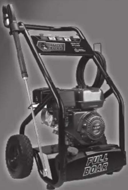
PETROL PRESSURE WASHER
• 3200 PSI MAX PRESSURE
- 7HP ENGINE
• 10M HIGH PRESSURE HOSE
natural_image
Black-and-white photo of a Full Boar pressure cooker with visible branding and model number (no text or symbols on the device body beyond branding)INSTRUCTION MANUAL

WARNING: Read all safety warnings and all instructions. Failure to follow the warnings and instructions may result in electric shock, fire and/or serious injury. Save all warnings and instructions for future reference.
SPECIFICATIONS - MODEL NO. FBPPW-3200
Engine: 7.0 HP, 4-stroke
Displacement: 208cc
Rated flow: 10 l/min
Fuel type: Unleaded petrol 91 RON
Fuel tank capacity: 3.6 litres
Oil type: SAE30, 10W30
Oil sump capacity: 600 ml
Detergent tank: 4.9 litres
Permissible pressure: 3200 psi (220 bar)
Max. inlet water temp.: 50°C
Noise level: 93 dB
Gross weight: 28 kg
KNOW YOUR PRODUCT
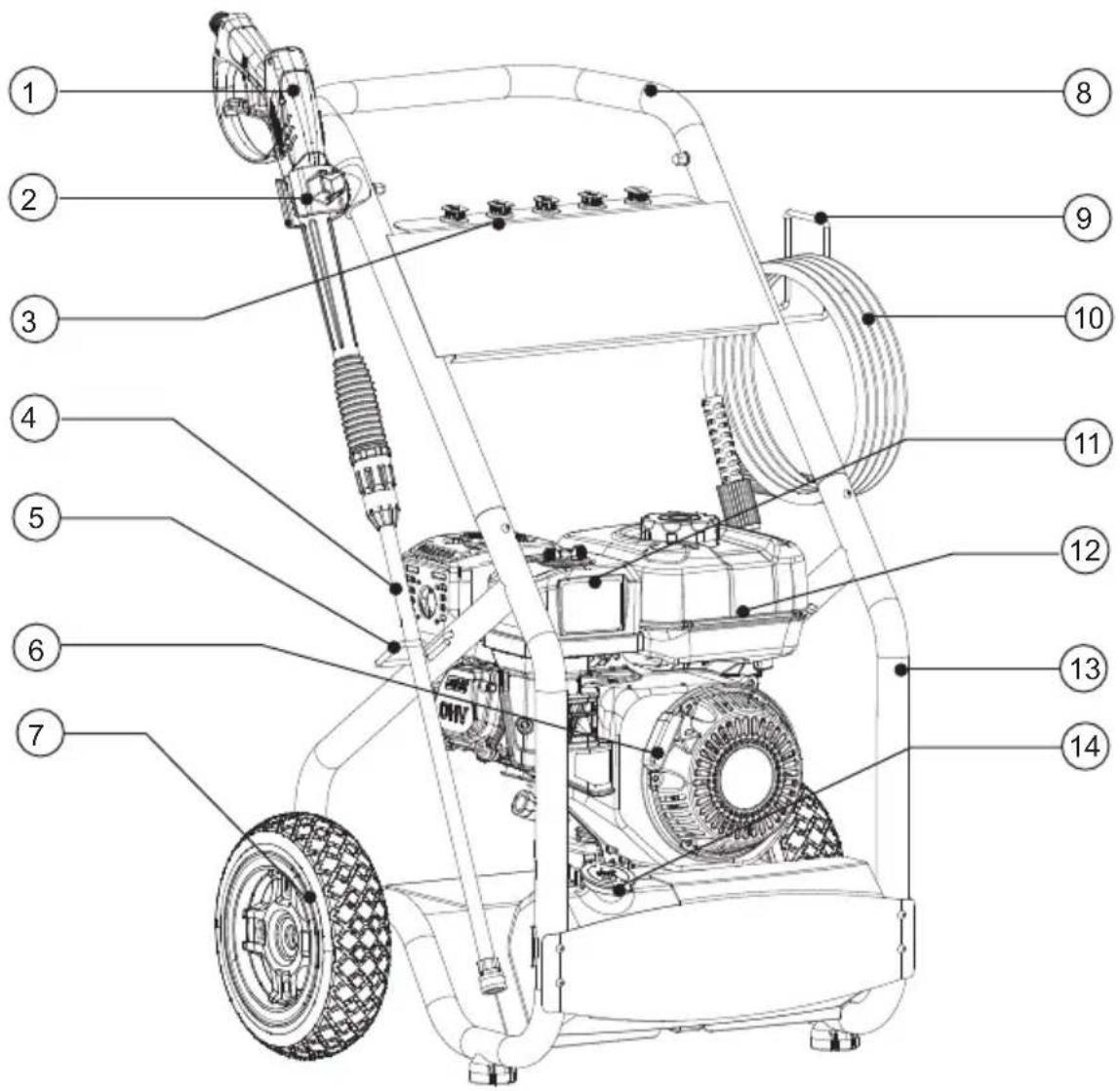
KNOW YOUR PRODUCT (cont.)
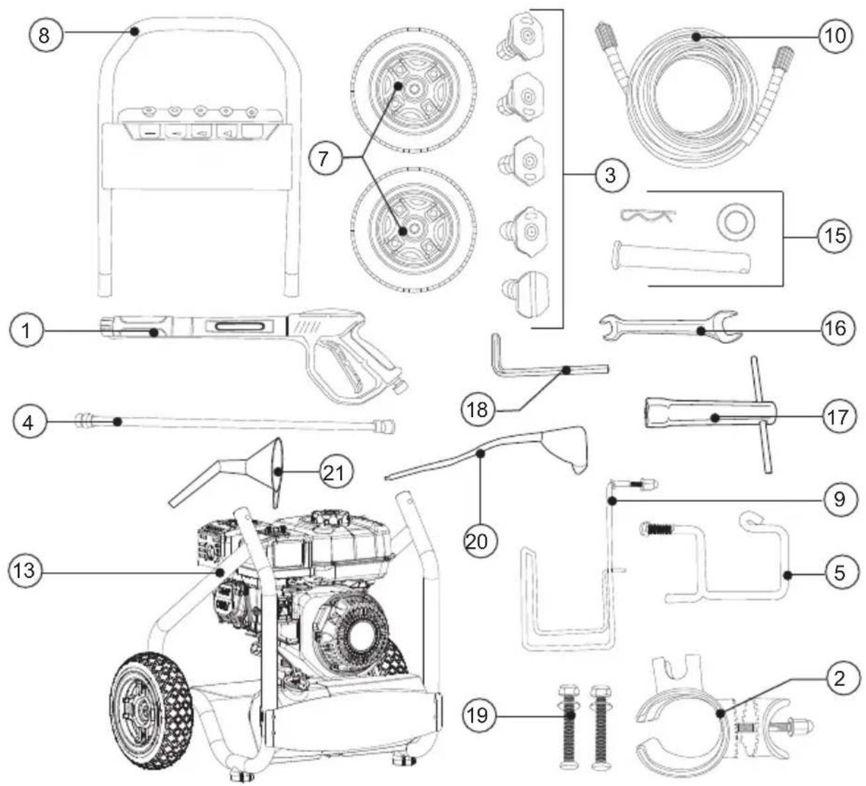
- Spray gun
- Spray gun holder (c/w nut & washer)
- Spray nozzles x 5
- Spray gun lance
- Lance holder (c/w nut & washers)
- Recoil starter
- Wheel x 2
- Top handle
- Hose holder (c/w nut & washers)
- High pressure hose
-
Air filter
-
Fuel tank
- Base frame
- Detergent tank cap
- Wheel axle, washer & R-clip x 2
- Spanner
- Spark plug tool
- Hex key
- Handle securing set x 2
- Oil funnel
- Fuel funnel
TABLE OF CONTENTS
SPECIFICATIONS...... Page 02
KNOW YOUR PRODUCT...... Page 02
INTRODUCTION...... Page 05
SAFETY INSTRUCTIONS...... Page 05
ASSEMBLY Page 09
SET-UP & PREPARATION...... Page 11
CONTROLS...... Page 17
MAINTENANCE...... Page 21
STORAGE......Page 23
TROUBLESHOOTING...... Page 25
DESCRIPTION OF SYMBOLS...... Page 27
CONTENTS...... Page 27
WARRANTY...... Page 28
INTRODUCTION
Congratulations on purchasing a Full Boar Petrol Pressure Washer.
Your Full Boar Petrol Pressure Washer FBPPW-3200 is designed to deliver a consistent high-pressure flow that's ideal for on-site cleaning bricks, driveways, patio's and pathway's or washing equipment, cars, boats, motorbikes with appropriate spray nozzle size for your application.
SAFETY INSTRUCTIONS

WARNING! When using mains-powered equipment, basic safety precautions, including the following, should always be followed to reduce the risk of fire, electric shock, personal injury and material damage.
Read and understand the manual prior to operating this tool.
Save these instructions and other documents supplied with this tool for future reference.
GENERAL SAFETY WARNINGS
RISK OF EXPLOSION OR FIRE
What can happen:
- Spilled petrol and its vapours can become ignited from cigarette sparks, electrical arcing, exhaust gases and hot engine components such as the muffler.
- Heat will expand fuel in the tank which could result in a fire.
- Operating the tool in an explosive environment could result in a fire.
- Muffler exhaust heat can damage painted surfaces, melt any materials sensitive to heat (such as siding plastic, rubber or vinyl) and damage live plants. Keep hot tool away from other objects.
- Improperly stored fuel could lead to accidental ignition. Fuel improperly secured could get into the hands of children or other unqualified persons.
How to prevent it:
- Shut off engine and allow it to cool before adding fuel to the tank.
- Use care when filling the tank to avoid spilling fuel. Move tool away from fuelling area before starting engine.
- Keep maximum fuel level 20mm below top of tank to allow for expansion.
- Operate and refuel in well ventilated areas free from obstructions. Never re-fuel indoors.
- Store fuel in a approved container (AS/NZS 2906-1999) for petrol. Store in a secure location away from the work area. Make sure the container is clearly marked "fuel".
GENERAL SAFETY WARNINGS (cont.)
RISK TO BREATHING
What can happen:
- Breathing exhaust fumes can cause serious injury or death.
How to prevent it:
- Operate tool in a well ventilated area. Avoid enclosed areas.
- Never operate unit in a location occupied by other people or animals.
SAVE THESE INSTRUCTIONS
1) Work area
a) Keep work area clean and well lit. Cluttered and dark areas invite accidents.
b) Do not operate petrol tools in explosive atmospheres, such as in the presence of flammable liquids, gases, or dust. Power tools create sparks which may ignite the dust or fumes.
c) Keep children and bystanders away while operating a petrol tool.
Distractions can cause you to lose control.
2) Personal safety
a) Stay alert, watch what you are doing and use common sense when operating a petrol tool. Do not use a power tool while you are tired or under the influence of drugs, alcohol, or medication. A moment of inattention while operating power tools may result in serious personal injury.
b) Use safety equipment. Always wear eye protection. Safety equipment such as a dust mask, non-skid safety shoes, hard hat, or hearing protection used for appropriate conditions will reduce personal injuries.
c) Remove any adjusting key or wrench before turning the tool on. A wrench or a key that is left attached to a rotating part of the petrol tool may result in personal injury.
d) Do not overreach. Keep proper footing and balance at all times. This enables better control of the petrol tool in unexpected situations.
e) Dress properly. Do not wear loose clothing or jewellery. Keep your hair, clothing and gloves away from moving parts. Loose clothes, jewellery or long hair can be caught in moving parts.
f) If devices are provided for the connection of dust extraction and collection facilities ensure that these are connected and properly used. Use of these devices can reduce dust-related hazards.
3) Petrol tool use and care
a) Do not force the petrol tool. Use the correct petrol tool for your application. The correct petrol tool will do the job better and safer at the rate for which it was designed.
b) Do not use the petrol tool if the switch does not turn it on and off. Any petrol tool that cannot be controlled with the switch is dangerous and must be repaired.
c) Turn tool off completely before making any adjustments, changing accessories, or storing petrol tools. Such preventive safety measures reduce the risk of starting the petrol tool accidentally. Hair can be caught in moving parts.
GENERAL SAFETY WARNINGS (cont.)
d) Store idle petrol tools out of the reach of children and do not allow persons unfamiliar with the petrol tool or these instructions to operate the petrol tool. Petrol tools are dangerous in the hands of untrained users.
e) Maintain petrol tools. Check for misalignment or binding of moving parts, breakage of parts and any other condition that may affect the petrol tool's operation. If damaged, have the petrol tool repaired before use. Many accidents are caused by poorly maintained petrol tools.
f) Keep cutting tools sharp and clean. Properly maintained cutting tools with sharp cutting edges are less likely to bind and are easier to control.
g) Use the petrol tool, accessories and tool bits etc., In accordance with these instructions and in the manner intended for the particular type of petrol tool, taking into account the working conditions and the work to be performed. Use of the petrol tool for operations different from intended could result in a hazardous situation.
h) This appliance is not intended for use by persons (including children) with reduced physical, sensory or mental capabilities, or lack of experience and knowledge, unless they have been given supervision or instruction concerning use of the appliance by a person responsible for their safety.
i) Children should be supervised to ensure that they do not play with the appliance.
4) Service
a) Have your petrol tool serviced by a qualified repair personnel using only identical replacement parts. This will ensure that the safety of the petrol tool is maintained.

WARNING! The engine and muffler becomes very hot during operation and remains hot for a while after stopping the engine. Be careful not to touch there components while it is hot. Let the engine cool before storing indoors.

WARNING! Exhaust contains poisonous carbon monoxide. Do not operate pressure washer in confined area. Be sure to operate the pressure washer in a well-ventilated environment or with an aerator. Using a pressure washer indoors will kill you in minutes. Never use in the home or in a partly enclosed area such as garages. Only use outdoors and far from open windows doors and vents.

WARNING! Engine exhaust contains carbon monoxide, a poisonous gas that could kill you in minutes. You cannot smell it, see it, or taste it. Even if you do not smell exhaust fumes, you could still be exposed to carbon monoxide gas. If you start to feel sick, dizzy, or weak while using this product, get fresh air right away. See a doctor. You may have carbon monoxide poisoning.

WARNING! Do not operate in hazardous location e.g. Where there may be a risk of explosion of petrol fumes, leaking gas or explosive dust.

WARNING! Do not operate in a confined area where exhaust gases, smoke or fumes could reach dangerous concentrations.

WARNING! Do not refuel while engine is running.
PRESSURE WASHER SAFETY WARNINGS

WARNING! This appliance is not intended for use by persons (including children) with reduced physical, sensory or mental capabilities, or lack of experience and knowledge, unless they have been given supervision or instruction concerning use of the appliance by a person responsible for their safety.
- Unsafe operation of your high pressure cleaner could lead to serious injury or death to you or others.
- The spray gun/wand is a powerful cleaning tool that could look like a toy to a child.
- Reactive force of spray results in gun/lance movement, potentially causing the operator to slip, fall or misdirect the spray. Improper control of gun/wand can result in injuries to self, others and property damage.
How to prevent it
- Become familiar with the operation and controls of the pressure cleaner.
- Keep children away from the pressure cleaner at all times.
- Never modify or remove the safety features of this product.
- Do not operate the machine with missing, broken or unauthorised parts.
- Never leave wand unattended while unit is running.
- Keep work area free of obstacles.
- Stand on stable surface and grip gun/lance firmly. Expect the gun to kick back when engaged
1) Do not use to pump flammable or explosive liquids such as gasoline, fuel oil, kerosene, solvents or thinners. Pump should only be used with liquids compatible with water blaster component materials. Failure to follow to this warning can result in serious personal injury, death and/or property damage.
2) Water high presser cleaner must be located on a solid level surface. Pump could tip or fall causing serious injury. 3) Do not hold or suspend pump by means of a discharge pipe. Pipe could break or come loose.
WARNING!: This appliance has been designed for use with the cleaning agent supplied or recommended by the manufacturer. The use of other cleaning agents or chemicals may adversely affect the safety of the appliance.
WARNING!: Do not use the appliance within range of persons unless they wear protective clothing.
WARNING!: High pressure jets can be dangerous if subject to misuse. The jet must not be directed at persons, live electrical equipment or the appliance itself.
- Do not direct the jet against yourself or others in order to clean clothes or foot-wear.
- To ensure appliance safety, use only original spare parts from the manufacturer or approved by the manufacturer.
WARNING!: High pressure hoses, fittings and couplings are important for the safety of the appliance. Use only hoses, fittings and couplings recommended by the manufacturer.
- Do not use the appliance if a supply cord or important parts of the appliance are damaged, e.g. safety devices, high pressure hoses, trigger gun.
WARNING!: Water that has flowed through back flow preventer is considered to be non-potable.
ASSEMBLY

WARNING! Some parts are heavy, two-person lift may be required to avoid injury.

WARNING! Ensure the tool has been shut off and completely stopped before performing any of the following operations.
Wheels & axle
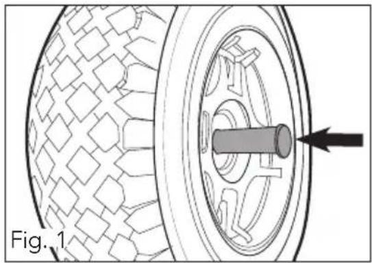
Parts required: Wheel x 2 (7), wheel axle, washer & R-clip x 2 (15)
- Slide a axle onto the wheel (7) (fig. 1).
natural_image
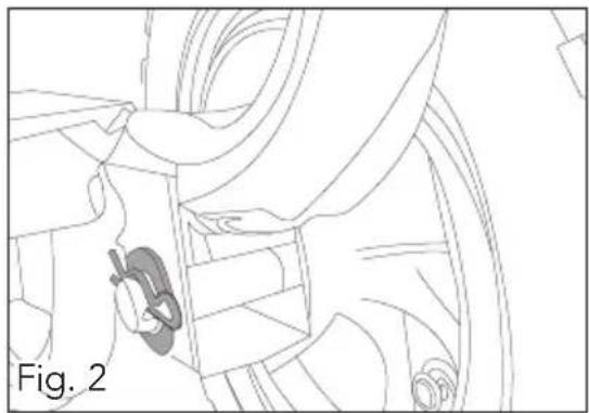
Technical diagram of a tire assembly with a central component and an arrow indicating direction (no text or symbols)- Slide the axle through the hole in the base frame (13) wheel bracket and secure in place with washer and R-clip (fig. 2).
natural_image
Technical line drawing of a mechanical assembly with no visible text or symbols- Repeat above steps for the opposite side.
Top handle
Parts required: Top handle (8), Handle securing set x 2 (19)
-
Place the top handle (8) onto the base frame (13) aligning the holes in the frame with the holes in the handle.
-
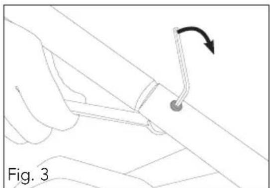
From the handle securing set (19), fit bolts through the holes and fasten the nuts using spanner (16) & hex key (18) (fig. 3).
natural_image
Diagram of a hand holding a tool with an arrow indicating rotation, labeled 'Fig. 3' (no text or symbols on the diagram itself)ASSEMBLY (cont.)
Spray gun holder
Parts required: Spray gun holder (2) & lance holder (5).
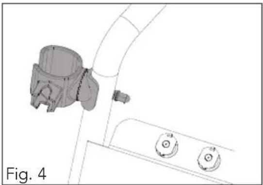
- Attach the spray gun holder (2) to the top handle frame (fig. 4).
natural_image
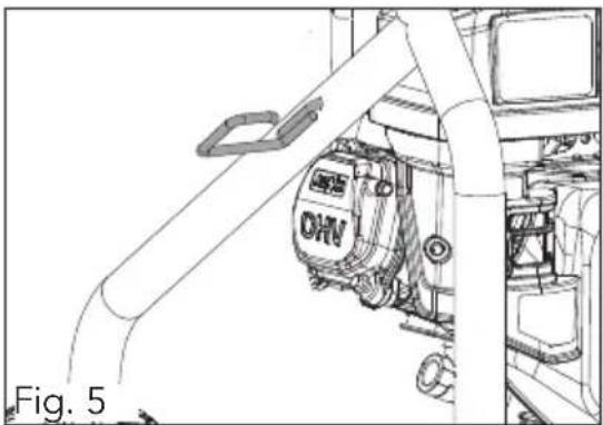
Technical line drawing of a mechanical component with two circular buttons and a cylindrical housing (no text or symbols)- Attach lance holder (5) to base frame (13) (fig. 5).
natural_image
Technical line drawing of a mechanical assembly with no visible text or symbolsHigh pressure hose holder (9)
Parts required: High pressure hose holder (9).
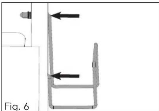
- Place hose holder (9) onto top handle (8), secure with dome nut & washers (fig. 6).
natural_image
Technical line drawing of a mechanical component with arrows indicating direction (no text or symbols)SETUP & PREPARATION

WARNING! To avoid pump damage, you must assemble the lance to the spray gun and attach all hoses before you start the engine.
Note: Remove and discard the clear shipping caps from the pumps high pressure threads.
Attaching spray gun and lance
-
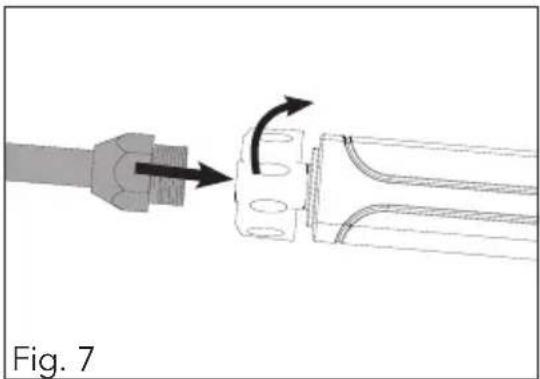
Thread lance (4) onto spray gun (1) (fig. 7).
-
Tighten the collar by hand to secure the lance to the spray gun.
natural_image
Diagram showing a mechanical component being inserted into a housing, with arrows indicating direction (no text or symbols)Attaching high pressure hose (10)
-
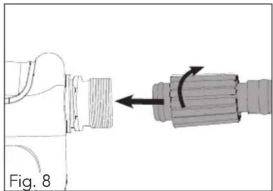
Uncoil high pressure hose (10) and thread one end onto the spray gun (1) (fig. 8).
-
Tighten the collar by hand to secure the hose to the spray gun.
natural_image
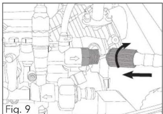
Mechanical assembly diagram showing a component being rotated into a cylindrical shaft (no text or symbols)3 Thread the opposite end onto the high pressure pump outlet (fig. 9).
- Tighten the collar by hand to secure.
natural_image
Technical diagram of a mechanical assembly with directional arrows indicating movement or force (no text or symbols present)SETUP & PREPARATION (cont.)
Spray nozzle selection
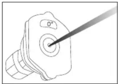
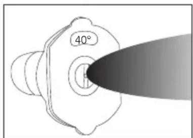
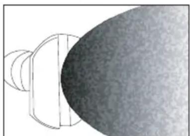
Included are five spray nozzles (3), each nozzle is colour coded and provides a specific spray pattern and pressure for a particular application.
Note: To prevent damage to your surface and to select an appropriate spray nozzle size for your application, always start with the lowest pressure nozzle size (white) and continue changing to the higher nozzle size until the best work result is achieved.
Red - 0° Jet Nozzle: Delivers a pinpoint stream of pressurized water and is extremely powerful. Should only be used on surfaces that can withstand high pressure such as concrete or metal.
Yellow – 15° Narrow Fan Nozzle: Delivers a powerful pattern for intense cleaning of small ares. Should only be used on surfaces and materials that can withstand high pressure.
Green – 25° Medium Fan Nozzle: Delivers a powerful pattern for intense cleaning of larger ares. Should only be used on surfaces and materials that can withstand medium to high pressure from the nozzle.
White – 40° Wide Fan Nozzle: Delivers a less powerful stream of water. Covers a wide area and should be used for most general cleaning applications.
Black – Low Pressure Detergent: Delivers the weakest stream of the five nozzles. Used for detergent and cleaning solutions.
natural_image
Technical line drawing of a mechanical component with a pointed tip and circular center (no text or symbols)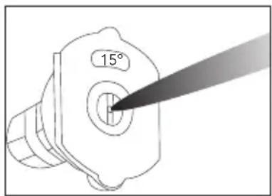
natural_image
Technical line drawing of a mechanical component with a 15° angle indicator (no text or symbols beyond the label)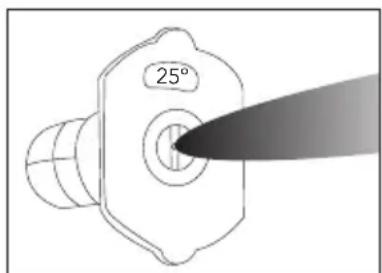
natural_image
Diagram of a mechanical component with a circular cross-section and a textured surface (no text or symbols)SETUP & PREPARATION (cont.)
Attaching spray nozzle (3)

WARNING! Never place hands in front of nozzle. Never grasp hose or fittings during pressure washer operation. Never attempt to attach or remove spray gun lance or hose fittings while pressure washer system is pressurized. Stop engine and lock gun trigger before attempting to change pressure nozzle.
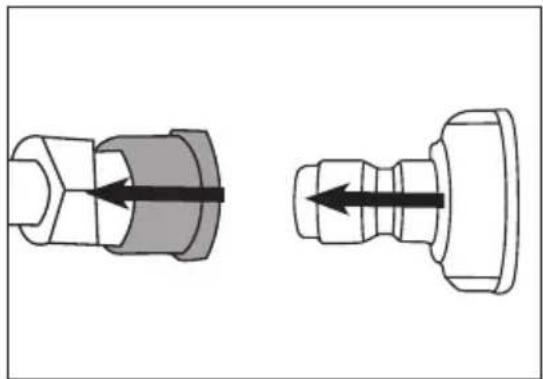
- Pull back and hold quick connector on lance (4) (fig. 10).
- Insert spray nozzle (3) and release quick connector (fig. 11).
Note: Ensure correct fitment to prevent nozzle being forced out of the connector by water pressure.
- To detach, pull back quick connector to eject the spray nozzle.
natural_image
Diagram showing two mechanical components with arrows indicating direction (no text or symbols)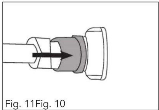
natural_image
Diagram of a mechanical component with a directional arrow, labeled Fig. 11 and Fig. 10 (no text or symbols on the diagram itself)Attaching water supply

WARNING! Never let the engine run without water. Failure to do so may damage the pump.
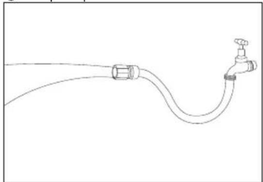
- Run water through garden hose to remove any foreign matter before attaching to the pump (fig. 12).
- Attach garden hose (min. I/D ∅½") to the inlet on the pump (fig. 13).
Note: The pump requires a minimum water supply of 15 l/min at 20 psi to avoid damaging the pump due to insufficient water supply.
natural_image
Line drawing of a pipe with a valve and bulb, no text or symbols present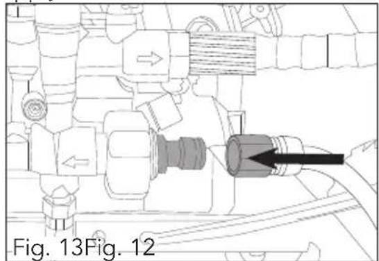
natural_image
Technical line drawing of a mechanical assembly with directional arrows and a highlighted component (no text or symbols)SETUP & PREPARATION (cont.)
-
Turn on the water supply.
-
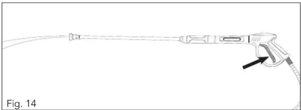
Squeeze trigger on the gun until there is a steady flow of water from the nozzle (3) (fig. 14). Release the trigger to stop water flow.
natural_image
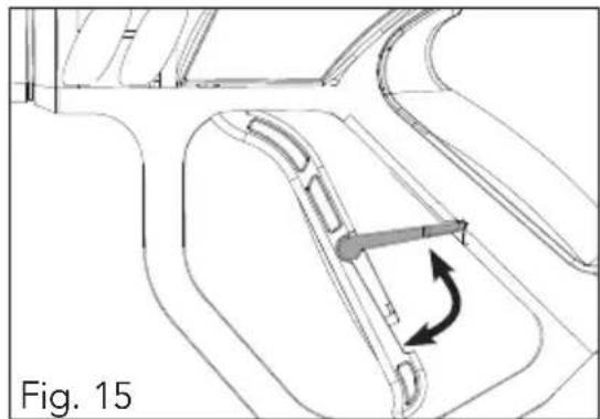
Line drawing of a medical or laboratory device with a pointed tip and cable, labeled 'Fig. 14' (no text or symbols on the device itself)Note: The trigger can be locked to prevent accidental spraying. Disengage trigger lock before squeezing the trigger (fig. 15).
natural_image
Technical line drawing of a mechanical component with an arrow indicating rotational motion (no text or symbols)SETUP & PREPARATION (cont.)
Adding engine oil
Note: The petrol pressure washer is shipped without oil and must be filled before starting. Engine sump capacity 600 ml. (Use SAE30 or 10W30 oil).
- Place pressure washer on a flat, level surface with the engine stopped.
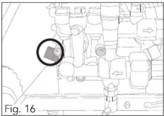
- Remove the oil filler cap and wipe the dipstick with a clean rag. Check the oil level by inserting the dipstick in the filler hole without screwing it in and then removing it again (fig. 16).
- If the oil level is below the end of the dipstick, refill (use funnel (20), do not tip pressure washer) until it registers on the halfway mark of the dipstick (fig. 17). Use premium quality 4-stroke engine oil. Recommended SAE30 or 10W30 for most climate conditions in Australia.
Note: Low Oil Cutout will shut off the engine if the oil level becomes lower than required.
natural_image
Diagram of a military vehicle with a highlighted rectangular object, labeled Fig. 16 (no readable text or symbols)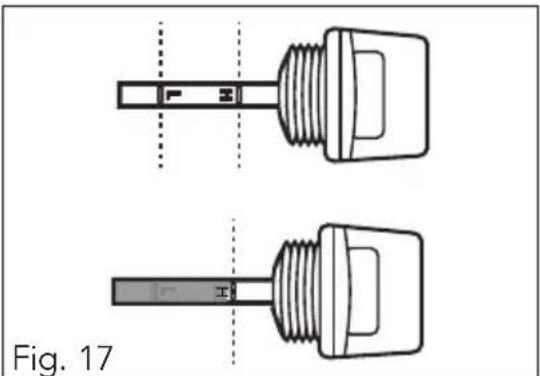
natural_image
Technical line drawing of two mechanical components with threaded ends and a central shaft, labeled Fig. 17 (no text or symbols on the components themselves)This protects your pressure washer engine from operating without proper lubrication.
If the engine shuts off and oil level is within specifications check to see if the pressure washer is sitting at an angle that forces oil to shift. Place on an even surface, if the engine fails to start, the oil level may not be sufficient to deactivate low oil level sensor. Add oil as described above.

WARNING! Never use non-detergent oil or 2-stroke engine oil. This may damage the engine beyond repair.
SETUP & PREPARATION (cont.)
Adding fuel

WARNING! Keep away from cigarettes, smoke and sparks when refuelling the engine. Always refuel in a well-ventilated location.
WARNING! Be careful not to spill fuel when refuelling. Spilled fuel or fuel vapour may ignite. If any fuel is spilled, make sure the area is dry before starting the engine.
WARNING! Do not over fill the fuel tank (12).
WARNING! Do not refill tank (12) while engine is running or hot.
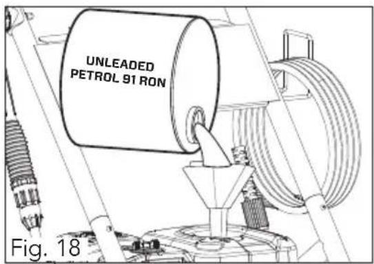
Note: Only use unleaded 91 RON (Research Octane Number) petrol. Purchase fuel in quantities that can be used every 30 days to prevent gum or foaming inside the container and/or fuel tank.
- Place the pressure washer on a flat level surface.
- Ensure the engine is switched OFF.
- Remove the fuel cap from the top of the fuel tank (12).
- Carefully fill the tank (12) with fuel (fig. 18).
- Fasten the fuel cap and clean any spillage.
OPERATION
Starting the engine

WARNING! Ensure you have filled the engine sump with engine oil before starting the engine. The dipstick must indicate the oil level is at maximum for the unit to start.

WARNING! Ensure you have connected and turned on the water supply. Damage to equipment resulting from failure to follow this instruction will void warranty.
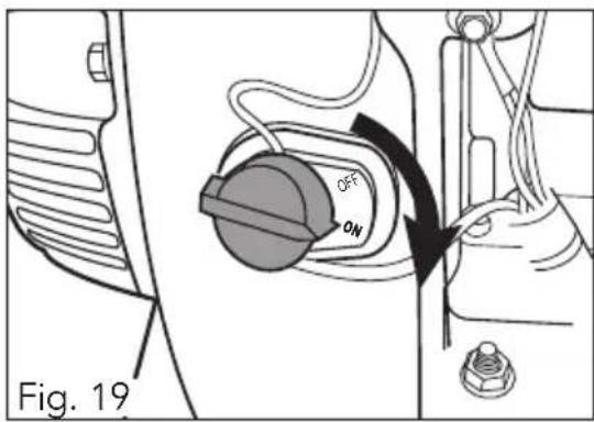
- Engine on/off switch – Move the engine on/off switch to the ON position (fig. 19).
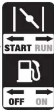
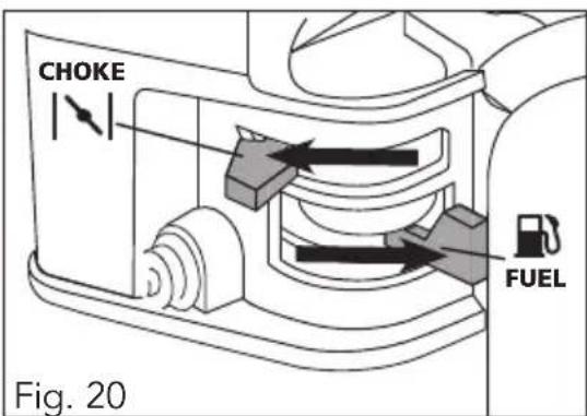
- Fuel - Move the fuel lever right, ON (open) position (fig. 20).
- Choke - Move the choke lever to the left, choke (closed) START position (fig. 20).
Note: If the engine is still hot, closing the choke is not necessary.
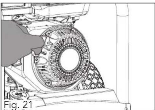
- Recoil starter - Grip the recoil starter (6) and slowly pull until resistance is felt, then pull the recoil starter rapidly. Allow the rope to rewind slowly and if necessary, repeat this procedure until the engine starts (fig. 21).
- Once started move the choke lever fully right RUN position.
natural_image
Technical line drawing of a mechanical assembly with a hand adjusting a circular component (no text or symbols)OPERATION (cont.)
Stopping the engine
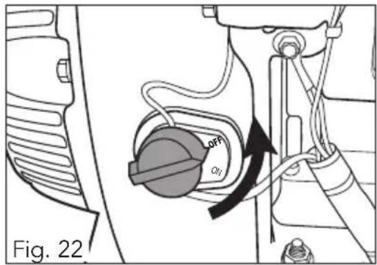
- Move the engine on/off switch to the OFF position (fig. 22).
- Move the fuel lever left OFF, (closed) position.
Washing / Cleaning

WARNING! The high pressure stream of water that this machine produces can cut through skin and its underlying tissues, leading to possible amputation. Spray gun traps high water pressure, even when the engine is stopped and water is disconnected, which can cause injury.

WARNING! Always wear approved safety glasses when operating pressure washer.
- Firmly grip spray gun (1) with both hands.

WARNING! The spray gun will kick back when the trigger is first pulled.
- Point the nozzle (3) to a safe direction and squeeze the trigger to begin spraying.
- When finished, release the trigger to stop water flow.
Using detergents
Most cleaning tasks can be completed with the pressure washer alone. For others, it is advantageous to use detergent. Use only liquid detergents designed specifically for use with pressure washers.
Note: Detergents, soaps, cleaning solvents will not siphon when a high pressure nozzle is used. Use the low pressure detergent nozzle (black).
- Prepare detergent solution as recommended by the manufacturer.
- Remove the detergent tank lid (14) and fill with prepared detergent solution. Replace the detergent tank lid (14).
- Lock the trigger and attach the low pressure detergent nozzle to the lance.
- Unlock and squeeze the trigger to apply detergent. When finished, release trigger to stop water flow.
OPERATION (cont.)
Usage tips
- For most effective cleaning, keep spray nozzle from 200 - 600 mm away from cleaning surface.
- If you get the spray nozzle too close, especially using high pressure nozzles, you may damage surface being cleaned.
- Apply a high pressure spray to a small area, and then check the surface for damage. If no damage is found, it is okay to continue cleaning.
- When using detergents, apply to a dry surface starting at the lower potion of area to be washed and work upward, using long, even, overlapping strokes.
- Allow detergents to soak in for 3 - 5 minutes before washing and rinsing. Reapply as needed to prevent surface from drying. To prevent streaking, do not allow detergent to dry on the surface.
- Wetting the surface before applying detergent is not recommended as it dilutes the detergent and reduces its cleaning ability.
- To rinse detergents, replace the nozzle with an appropriate high pressure nozzle (3) (see Spray nozzle selection). Squeeze the trigger and wait for the detergent to clear. Start at the top of the area to be rinsed, working down the same overlapping strokes as you used for washing and applying detergent.
- Never use the pressure washer water inlet to siphon detergents.
To flush system
When you have completed the use of detergent;
- Turn off the engine and fill the detergent tank with water.
- Remove the nozzle and then start the engine.
- Point the lance toward a safe direction and squeeze the trigger to flush clean water through the detergent tank and the system until it is thoroughly clean.

WARNING! Leaving cleaning solutions inside the pressure pump could damage it. Damaged created by leaving soaps and cleaning solutions inside the pump can void the warranty.
OPERATION (cont.)
Shutting down
- Stop the engine (see Stopping the engine).
- Turn off the water supply and disconnect garden hose from pressure washer.
- Point the lance toward a safe direction and squeeze the trigger to release any remaining water in the system.
- Store spray gun and hose on the brackets provided on the frame.
- Allow engine to cool down before storing.

WARNING! Never turn off water supply with engine running. This will cause the pressure pump to overheat resulting in internal damage.
MAINTENANCE
Regular maintenance will improve performance and extended the life of pressure washer. The pressure washer warranty does not cover items that have been subjected to operator abuse or negligence. To receive full value from the warranty, the operator must maintain the pressure cleaner as instructed in this manual.
- Some adjustments will need to be made periodically to properly maintain the pressure washer.
- All maintenance in this manual should be made at least once each season.
- Once a year you should clean or replace the spark plug, clean or replace the air filter and check the spray gun and lance extension assembly for wear. A new spark plug and clean air filter assure proper fuel-air mixture and help your engine run better and last longer.
- Keep your pressure washer upright when not in use and out of weather conditions.
Before each use
- Check engine oil level.
- Check air filter for build-up.
- Check water inlet screen for damage.
- Check high pressure hose for leaks or damaged kinks.
- Check chemical injection hose and filter for damage.
- Check spray gun and lance extension for leaks or any build up of foreign matter.
- Rinse out garden hose to flush out debris.
High pressure hose
The high pressure hose can develop leaks from wear, kinking, or abuse. Inspect the hose each time before using it. Check for cuts, leaks, abrasions or bulging of cover, damage or movement of couplings. If any of these conditions exist, replace the hose immediately.

WARNING! The high pressure stream of water that this equipment produces can pierce skin and its underlying tissues, leading to serious injury and possible amputation. NEVER repair high pressure hose. Replace it. Replacement hose rating MUST exceed maximum pressure rating of unit.
Spray gun & lance
Examine the hose connection to the spray gun and make sure it is secure. Test the trigger by pressing it and making sure it "springs back" into place when you release it. Put the trigger lock in the OFF position and test the trigger. You should not be able to press the trigger.
MAINTENANCE (cont.)
Nozzles
A pulsing sensation felt while squeezing the spray gun trigger may be caused by excessive pump pressure. The principal cause of excessive pump pressure is a nozzle (3) clogged or restricted with foreign materials, such as dirt, etc. To correct the problem, immediately clean the nozzle (3) following these instructions:
-
Shut off engine and turn off water supply.
-
Remove nozzle (3) from end of lance (4).
-
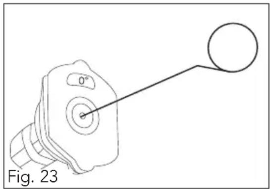
Use a small paper clip or pin to free any foreign material clogging or restricting nozzle (3) (fig. 23).
-
Using a garden hose, remove additional debris by back flushing water through lance (4). Back flush between 30 to 60 seconds.
-
Reconnect lance (4) to spray gun (1).
-
Reconnect water supply, turn on water, and start engine.
-
Test pressure cleaner by operating with each quick connect nozzle (3).
natural_image
Technical line drawing of a mechanical component with a circular end and 0° angle annotation (no text or symbols beyond label)Water inlet filter
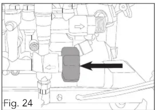
The water inlet screen filter should be checked periodically and cleaned if necessary (fig. 24).
natural_image
Technical line drawing of a mechanical assembly with no visible text or symbols
WARNING! Never operate pressure washer without screen filter in place. Impurities entering pressure pump can cause internal damage.
Note: Ozito Industries will not be responsible for any damage or injuries caused by the repair of the air mover by an unauthorised person or by mishandling of the petrol pressure washer.
STORAGE
Water should not remain in the unit for long periods of time. Sediments or minerals can deposit on pump parts and "freeze" pump action. If you do not plan to use the pressure cleaner for more than 30 days, follow this procedure:
Note: Use 1 litre automotive antifreeze / radiator coolant (non-alcohol based).
- Shut off engine and let it cool, then remove high pressure and garden hoses. Disconnect spark plug wire from spark plug.
- Empty pump of all pumped liquids by pulling recoil starter (6) about 6 times. This should remove most liquid in pump.
- Use automotive antifreeze to prevent corrosion build up and freezing of pump. (See Protecting the pump).
- Store unit in a clean, dry area and keep upright.
Protecting the pump
To protect the pump from damage caused by mineral deposits or freezing, use automotive antifreeze to treat pump. This prevents freeze damage and lubricates pistons and seals.
Note: Automotive antifreeze is available as an optional accessory. It is not included with the pressure cleaner. Automotive antifreeze can be found at your local supermarket, petrol station or automotive store.

WARNING! You must protect your unit from freezing temperatures. Failure to do so will permanently damage your pump and render your unit inoperable. Freeze damage is not covered under warranty.

WARNING! Read and follow all cautions and warnings on the automotive antifreeze container label. Always wear eye protection when using automotive antifreeze.

WARNING! Automotive antifreeze will drip from pump after treatment and will stain wood and concrete. Protect surfaces from dripping automotive antifreeze.
- Make sure the pressure cleaner is turned off and disconnected from supply water.
- Read and follow all instructions and warnings given on the automotive antifreeze container.
- Draw antifreeze into the pump by pouring the solution into a 1 metre section of garden hose connected to inlet adapter, elevate the free end of the hose and pull recoil starter (6) twice.
STORAGE (cont.)
- Cover pressure washer with a suitable cover that does not retain moisture such as a plastic or plastic coated tarp.
- Store pressure washer in a clean dry area.
Preparing for use after storage
- Slowly pull the recoil starter (6) a few times to clean oil from cylinder or to eject any antifreeze from the pump which was added prior to storage.
- Remove the spark plug from the cylinder. Wipe oil from spark plug and return to the cylinder and tighten.
- Reconnect spark plug lead.
TROUBLESHOOTING
| Symptom Possible Cause Suggested Solution | ||
| The engine does not start or starts and runs rough. | Flooded Wait 5 minutes and re-crank engine. | |
| Engine switch in OFF position. | Move switch to ON position | |
| Fuel lever in OFF position. | Move lever to ON position | |
| Fuel tank empty Fill fuel tank with fuel | ||
| Spark plug disconnected Connect spark plug | ||
| Faulty spark plug Replace spark plug | ||
| Choke lever in wrong position | Adjust choke lever position | |
| Water in fuel Drain fuel tank carburettor; fill with fresh fuel. | ||
| Dirty air cleaner Clean or replace air cleaner | ||
| Engine shuts down when running. | Out of fuel Fill fuel tank | |
| Low engine oil Add oil. | ||
| Engine lacks power. Cylinder pressure is low Call Customer Service | ||
| Dirty air cleaner Replace air filter | ||
| No pressure or low pressure | Spray gun not set to high pressure | See Spray Nozzle Selection section |
| Inadequate water supply Water supply must be 15 l/min at 20 psi | ||
| Hose fitting leaks during high pressure | Tighten hose fitting. Use thread sealant tape if necessary. | |
| Nozzle obstructed Clean nozzle (see maintenance) | ||
| Water filter screen obstructed | Remove and clean. | |
| Air in hose Squeeze trigger to remove air | ||
| Choke lever in choke position | Move choke lever to RUN position | |
TROUBLESHOOTING (cont.)
| Symptom Possible Cause Suggested Solution | ||
| Pump will not draw detergent | Spray gun not set to low pressure. | See Spray Nozzle Selection section |
| Detergent solution too thick | Dilute solution. Detergent solution should have same consistency as water. | |
| Detergent build-up in detergent injector | Clean or replace. Call Customer Service. | |
| Water leaking at spray gun/lance connection | Worn or broken O-ring Replace O-rings | |
| Loose hose connection Tighten hose connection | ||
| Pump pulsates Nozzle o | obstructed Clean nozzle (See maintenance) | |
| Air in the system Squeeze trigger to remove air | ||
CARING FOR THE ENVIRONMENT
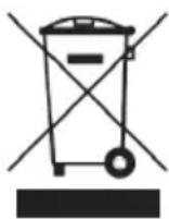
Power tools that are no longer usable should not be disposed of with household waste but in an environmentally friendly way. Please recycle where facilities exist. Check with your local council authority for recycling advice.

Recycling packaging reduces the need for landfill and raw materials. Reuse of recycled material decreases pollution in the environment. Please recycle packaging where facilities exist. Check with your local council authority for recycling advice.
DESCRIPTION OF SYMBOLS
| CC | Cubic Centimeters | rpm | Revolutions per minute | |
| psiPounds per square inch | HP | Horse power | ||
| I | Litres | ∅ | Diameter | |
| mm | Millimetres | BAR | Pressure rating | |
 | Oil | °C | Degress celsius | |
 | Read instruction manual | Regulator compliance mark | ||
 | Unleaded Petrol | Warning | ||
 | Choke control | Fire Hazard | ||
 | Carbon Monoxide | Hot Surface | ||
 | Poisonous Fumes | Wear eye and ear protection | ||
 | Sound pressure level | |||
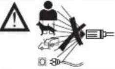 | Warning! High pressure jets can be dangerous if not used properly. Do not direct the jet at persons, animals, live electrical equipment or the pressure washer itself. | |||
CONTENTS
1 x Petrol pressure washer
1 x Gun & lance
5 x Spray nozzles
1 x High pressure hose
2 x Wheels
2 x Wheel axle, washer & R-clip
1 x Hose holder
Distributed by:
Ozito Industries Pty Ltd
AUSTRALIA (Head Office)
1-23 Letcon Drive, Bangholme Victoria, Australia, 3175
Telephone: 1800 069 486
1 x Lance holder
1 x Spray gun holder
1 x Spanner (M8 x M10)
1 x Hex key
1 x Spark plug tool
2 x Handle securing set
1 x Oil funnel
1 x Fuel funnel
WARRANTY
YOUR WARRANTY FORM SHOULD BE RETAINED BY YOU AT ALL TIMES. IN ORDER TO MAKE A CLAIM UNDER THIS WARRANTY YOU MUST RETURN THE PRODUCT TO YOUR NEAREST
BUNNINGS WAREHOUSE (see www.bunnings.com.au or www.bunnings.co.nz for store locations)
WITH YOUR BUNNINGS REGISTER RECEIPT. PRIOR TO RETURNING YOUR PRODUCT FOR
WARRANTY PLEASE TELEPHONE OUR CUSTOMER SERVICE HELPLINE:
Australia 1800 069 486
New Zealand 0508 069 486
TO ENSURE A SPEEDY RESPONSE PLEASE HAVE THE MODEL NUMBER AND DATE OF PURCHASE AVAILABLE. A CUSTOMER SERVICE REPRESENTATIVE WILL TAKE YOUR CALL AND ANSWER ANY QUESTIONS YOU MAY HAVE RELATING TO THE WARRANTY POLICY OR PROCEDURE.
1 YEAR WARRANTY
Your product is guaranteed for a period of 12 months from the original date of purchase. If a product is defective it will be repaired in accordance with the terms of this warranty. Warranty excludes consumable parts, for example: wheels, bearings.
The benefits provided under this warranty are in addition to other rights and remedies which are available to you under law. The warranty covers manufacturer defects in materials, workmanship and finish under normal use.
Our goods come with guarantees that cannot be excluded under Australian Consumer law & Consumer Guarantees Act 1993 (NZ). You are entitled to a replacement or refund for a major failure and to compensation for other reasonably foreseeable loss or damage. You are also entitled to have the goods repaired and replaced if the goods fail to be of acceptable quality and the failure does not amount to a major failure.
WARRANTY EXCLUSIONS
The following actions will result in the warranty being void.
If the tool has been operated on a supply voltage other than that specified on the tool.
If the tool shows signs of damage or defects caused by or resulting from abuse, accidents • or alterations.
- Failure to perform maintenance as set out within the instruction manual.
• If the tool is disassembled or tampered with in any way.
• The warranty excludes damage resulting from product misuse or product neglect.
This warranty is given by Ozito Industries Pty Ltd.
ABN: 17 050 731 756
Ph.1800 069 486
Australia/New Zealand (Head Office)
1-23 Letcon Drive, Bangholme, Victoria, Australia 3175
- PETROL PRESSURE WASHER
- INSTRUCTION MANUAL
- SPECIFICATIONS - MODEL NO. FBPPW-3200
- KNOW YOUR PRODUCT
- KNOW YOUR PRODUCT (cont.)
- TABLE OF CONTENTS
- INTRODUCTION
- SAFETY INSTRUCTIONS
- GENERAL SAFETY WARNINGS
- RISK OF EXPLOSION OR FIRE
- What can happen:
- How to prevent it:
- GENERAL SAFETY WARNINGS (cont.)
- RISK TO BREATHING
- SAVE THESE INSTRUCTIONS
- 1) Work area
- 2) Personal safety
- 3) Petrol tool use and care
- PRESSURE WASHER SAFETY WARNINGS
- How to prevent it
- ASSEMBLY
- Wheels & axle
- Top handle
- ASSEMBLY (cont.)
- Spray gun holder
- High pressure hose holder (9)
- SETUP & PREPARATION
- Attaching spray gun and lance
- Attaching high pressure hose (10)
- SETUP & PREPARATION (cont.)
- Spray nozzle selection
- Attaching spray nozzle (3)
- Attaching water supply
- Adding engine oil
- Adding fuel
- OPERATION
- Starting the engine
- OPERATION (cont.)
- Stopping the engine
- Washing / Cleaning
- Using detergents
- Usage tips
- To flush system
- Shutting down
- MAINTENANCE
- Before each use
- High pressure hose
- Spray gun & lance
- MAINTENANCE (cont.)
- Nozzles
- Water inlet filter
- STORAGE
- Protecting the pump
- STORAGE (cont.)
- Preparing for use after storage
- TROUBLESHOOTING
- TROUBLESHOOTING (cont.)
- CARING FOR THE ENVIRONMENT
- DESCRIPTION OF SYMBOLS
- CONTENTS
- AUSTRALIA (Head Office)
- WARRANTY
- YEAR WARRANTY
- WARRANTY EXCLUSIONS
Brand : Full Boar
Model : 3200PSI 7HP
Category : Pressure washer