A-151 - Synthesizer Doepfer - Free user manual and instructions
Find the device manual for free A-151 Doepfer in PDF.


| Product Type | Quad Sequential Switch (Eurorack synthesizer module) |
| Brand | Doepfer |
| Model | A-151 |
| Width | 8 HP (approx. 40.5 mm) |
| Height | 3U (approx. 128.5 mm) |
| Depth | Approx. 40 mm |
| Weight | Approx. 120 g |
| Power Supply | +12V: 30 mA, -12V: 10 mA (typical) |
| Voltage Range (Version 1) | -8V to +8V |
| Voltage Range (Version 2) | -12V to +12V (full A-100 range) |
| Main Functions | Quad sequential switch, trigger and reset inputs, four bi-directional I/O sockets, step number selection (2/3/4 on version 2) |
| Indicators | 4 LEDs showing active I/O |
| Additional Controls | Steps switch (version 2) to limit addressed steps to 2, 3 or 4 |
| Connections | Trig In, Res In, Common O/I, I/O 1–4 |
| Switching Function | Each trigger pulse advances common to next I/O; reset returns to first |
| Typical Applications | Switching VCO waveforms, four-step sequencing, switching filter types |
| Maintenance | Clean with dry cloth; no user-serviceable parts |
| Safety | Use only within specified voltage range; avoid exceeding power supply limits |
| Spare Parts / Repairability | Contact Doepfer or authorized dealer; module should only be repaired by qualified personnel |
| General Information | Part of Doepfer A-100 system; designed for modular synthesis |
Frequently Asked Questions - A-151 Doepfer
User questions about A-151 Doepfer
0 question about this device. Answer the ones you know or ask your own.
Ask a new question about this device
Download the instructions for your Synthesizer in PDF format for free! Find your manual A-151 - Doepfer and take your electronic device back in hand. On this page are published all the documents necessary for the use of your device. A-151 by Doepfer.
USER MANUAL A-151 Doepfer
1. Introduction
Module A-151 (Quad Sequential Switch) is like an electronic four-position rotary switch.
It includes trigger and reset inputs, four in / outputs, and a common out / input.
Each time a pulse is received at the trigger input socket, the common out / input is connected to the next in / output. After the fourth in / output, the next trigger makes it step back to the first again, and so on (see Fig. 1).
Voltages in the range -8V...+8V at the O/I resp. I/O sockets can be processed by the module.
Four LEDs indicate the active in / output (ie. the one that is connected to the out / input at any particular time).
A positive pulse at the reset input switches the out / input immediately back to the first in / output (see Fig. 1).
Version 2 of the module (from about 2005) is equipped with an additional switch that is used to set the number of steps to 2, 3 or 4. On top of that the new versions allows to switch audio or control signals within the full A-100 voltage range (i.e. -12V...+12V).
2. Overview
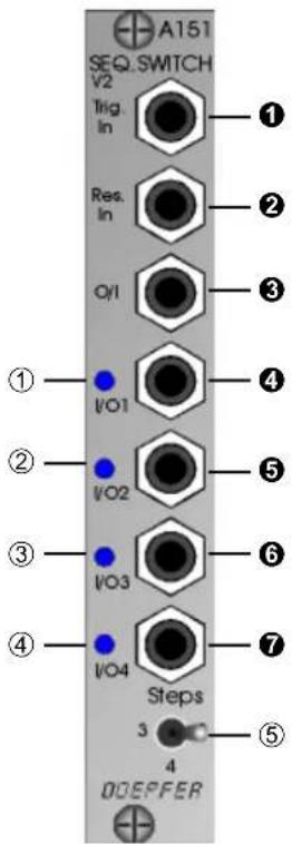
Indicators:
① LED: Indicator for in / output ④
② LED: Indicator for in / output ⑤
③ LED: Indicator for in / output ⑥
④ LED: Indicator for in / output ⑦
⑤ Steps: Switch for the limitation of the number of addressed steps to 2, 3 or 4 (available only in version 2)
In / Outputs:
① Trig. In : Input for trigger pulse
② Res. In : Input for reset pulse
③ O/I : Common out / input
④ I/O 1 : In / output 1
⑤ I/O 2: In / output 2
⑥ I/O 3 : In / output 3
⑦ I/O 4 : In / output 4
3. Indicators
① LED • ② LED • ③ LED • ④ LED
LEDs ① to ④ are the status indicators, showing which of sockets ④ to ⑦ is connected to the common out /input ③ at any moment.
⑤ Steps
This switch is used to limit the number of addressed in/outputs to 2, 3 or 4. The switch is available on in version 2 of the module (about since 2005).
4. In / Outputs
① Trig. In
Socket ① is the A-151's trigger input. With each new pulse (at the rising edge), the common out / input is switched to the next in / output.
After stepping to the fourth in / output the next trigger pulse sends the common out / input back to the first in / output again (see Fig. 1).

Don't forget that with a very fast repeating trigger, the switching process on the A-151 can produce audio-frequency modulation (see chapter 5, user examples).
② Res. In
If you want to over-ride the stepping sequence, and send the common out /input back to the first in / output, send a reset pulse to the reset input ② (see Fig. 1). The rising edge of this pulse immediately resets the common out / input to the first in / output.
Using the reset input, you can create repeated sequences which switch between three inputs or outputs (4 → 5 → 6 → 4 → 5 → 6 → 4...).
③ O/I
Socket ④ is the common out /input. Each time the A-100 is switched on, or a reset pulse is received, this socket is connected to the first in / output socket ④ (see Fig. 1).
④ I/O 1 • ⑤ I/O 2 • ⑥ I/O 3 • ⑦ I/O 4
Sockets ④ to ⑦ are the in / outputs.
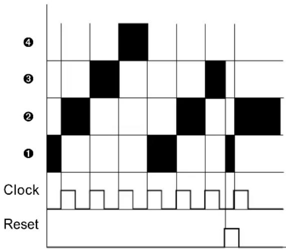
Fig. 1: How the A-151 switching works (■ : in / output connected)
The switches are bi-directional, so switching can take place from four inputs to one output, or four outputs to one input. Which process is happening at any one time will always be clear from looking at the modules connected.
Any signal from -8 V to +8 V at the O/I resp. I/O sockets can be processed by the A-151. Voltages less than -8V or more than +8V will lead to malfunction of the module ! It is possible to modify the module so that voltages in the range 0...+12V can be processed. You find a modification of the A-151 for signals in the range 0...+12V on our web site www.doepfer.com in the FAQ section (click to the FAQ button on the left side of the page).
Another solution for signals beyond -8V resp. +8V is to attenuate and/or to change the offset voltage of the signal. The A-129/3 attenuator/offset generator can be used for both purposes.
From version 2 of the module (from about 2005) the full voltage range of the A-100 (i.e. -12V...+12V) can be switched without any modification. Version 2 can be identified with the additional switch ⑤ Steps.
5. User examples
Switching VCO waveforms
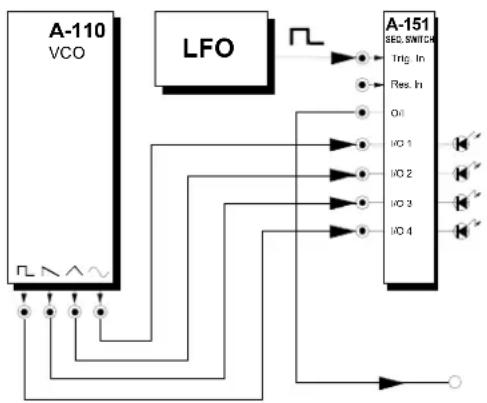
In the example in Fig. 2, every time a trigger pulse hits the A-151's trigger input socket, the VCO switches to a new waveform. Since very fast switching of the A-151 (by an LFO set to its fastest range, or even by a VCO) can produce audio frequency modulation - that is, changes so fast that the ear can't resolve them - the result is in effect a new waveform.
flowchart
graph TD
    A["A-110 VCO"] --> B["LFO"]
    B --> C["SEC SWITCH"]
    C --> D["I/O 1"]
    C --> E["I/O 2"]
    C --> F["I/O 3"]
    C --> G["I/O 4"]
    D --> H["Ground"]
    E --> H
    F --> H
    G --> H
    H --> I["Output"]
Fig. 2: Switching VCO waveforms

As an alternative to using an LFO or VCO to trigger the waveform sequencing, it's possible to get the VCO to trigger the switching itself. Simply connect the square wave output into the trigger input ① of the A-151.
Four-step tone sequencing
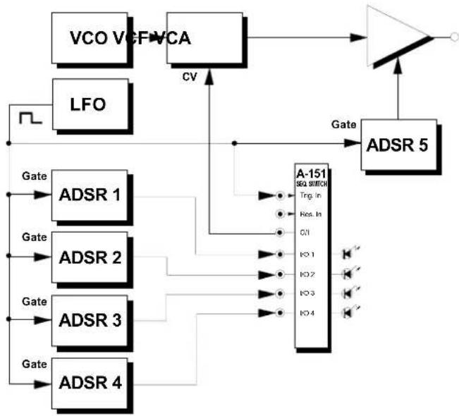
The patch in Fig. 3 on page 6 produces a four-step tonal sequence, with a different filter envelope for each of the four steps.
An LFO simultaneously triggers ADSRs 1 to 4 and the switch on the A-151, so that for each step the VCF is affected by a different one of the four envelopes.
ADSR 5 is also triggered by the LFO, and controls the VCA.

It's crucial to make the envelopes of all the ADSRs fit the LFO's speed.
flowchart
graph TD
    A["VCO V"] --> B["FFVCA"]
    C["LFO"] --> D["Gate"]
    E["ADSR 1"] --> F["Gate"]
    G["ADSR 2"] --> H["Gate"]
    I["ADSR 3"] --> J["Gate"]
    K["ADSR 4"] --> L["Gate"]
    M["CV"] --> N["A-151 SEQ SWITCH"]
    N --> O["Trg. In"]
    N --> P["Res. In"]
    N --> Q["C1"]
    N --> R["I0 1"]
    N --> S["I0 2"]
    N --> T["I0 3"]
    N --> U["I0 4"]
    N --> V["Output"]
    W["Gate"] --> X["ADSR 5"]
    X --> Y["Output"]
Fig. 3: Four-step tone sequencing

If you use a keyboard gate as the trigger instead of the LFO, each note played steps through to the next envelope.
Switching filter characteristics
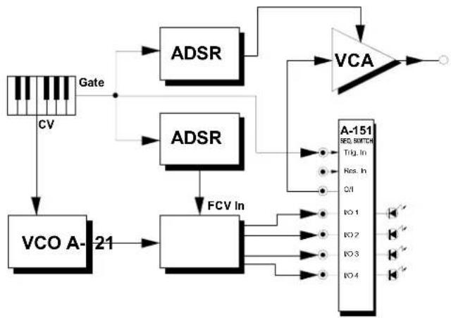
With the patch in Fig. 4, you can use an A-151 to step through each of the types of output in the A-121 multimode filter, one step for each note played.
flowchart
graph TD
    A["Gate"] --> B["CV"]
    B --> C["VCO A-21"]
    C --> D["FCV In"]
    D --> E["ADSR"]
    E --> F["VCA"]
    F --> G["A-151 SEC SWITCH"]
    G --> H["Pin 1"]
    G --> I["Pin 2"]
    G --> J["Pin 3"]
    G --> K["Pin 4"]
    F --> L["VCA"]
    L --> M["Output"]
Fig. 4: Switching filter characteristics
Brand : Doepfer
Model : A-151
Category : Synthesizer