
ZDIS150ZSS - Sorbet maker GE - Free user manual and instructions
Find the device manual for free ZDIS150ZSS GE in PDF.


| Product Type | Automatic Ice Maker |
| Brand | GE (Monogram) |
| Model | ZDIS150ZSS |
| Color | Stainless Steel |
| Dimensions (Product) | See cutout dimensions: 15-1/2" W (with filler strip) x 22-3/4" D (with panel) x 34-1/2" H (adjustable) |
| Cutout Width | 15-1/2" (including 1/2" filler strip) or 16-1/2" for custom panel |
| Cutout Depth | 22-3/4" (with 3/4" custom panel) |
| Electrical Requirements | 115 V, 60 Hz, 15 or 20 A, dedicated circuit, grounded 3-prong outlet |
| Water Supply Pressure | 30 – 120 psi |
| Recommended Water Line | 1/4" O.D. copper or GE SmartConnect tubing (not plastic other than SmartConnect) |
| Drain Type | Gravity drain; optional ZPK2 drain pump kit required if no floor drain |
| Water Filter | Included, installs in right side control housing |
| Ice Production | Not specified in manual; designed for automatic operation |
| Door Swing Reversible | Yes, instructions provided |
| Optional Accessories | ZIP75BB custom panel kit (black models), ZPK2 drain pump kit |
| Installation Type | Under-counter or freestanding, not for outdoor use |
| Ambient Temperature Range | 55°F – 110°F (13°C – 43°C), best at 70°F – 90°F |
| Power Cord Length | 66" (5.5 ft) |
| Grounding | Required; do not use extension cord or adapter |
| Service Contact | 1.800.444.1845 (US), 1.800.561.3344 (Canada) |
Frequently Asked Questions - ZDIS150ZSS GE
User questions about ZDIS150ZSS GE
0 question about this device. Answer the ones you know or ask your own.
Ask a new question about this device
Download the instructions for your Sorbet maker in PDF format for free! Find your manual ZDIS150ZSS - GE and take your electronic device back in hand. On this page are published all the documents necessary for the use of your device. ZDIS150ZSS by GE.
USER MANUAL ZDIS150ZSS GE
Installation Instructions
Automatic Ice maker
ZDIC150
ZDIS150
Design Guide
With Installation Instructions
- BEFORE YOU BEGIN:
Read these instructions completely and carefully.
- IMPORTANT:
Save these instructions for local inspector's use.
- IMPORTANT:
Observe all governing codes and ordinances.
- Note to Installer – Be sure to leave these instructions with the Consumer.
- Note to Consumer – Keep these instructions with your Owner's Manual for future reference.
WARNING:
This appliance must be properly grounded.
Failure to do so can result in death, fire or electrical shock. See "Power Supply," page 6.
⚠ AVERTISSEMENT :
If you received a damaged ice maker, you should immediately contact your dealer or builder.
Proper installation is the responsibility of the installer. Product failure due to improper installation is not covered under the GE Appliance Warranty. See the Owner's Manual for warranty information.
- Use this appliance only for its intended purpose.
Check with local utilities for electrical codes that apply in your area. Local codes vary. Installation, electrical connections and grounding must comply with applicable codes. In the absence of local codes, the ice maker should be installed in accordance with National Electrical Code ANSI/NFPA 70-1990 or latest edition.
For Monogram local service in your area, call 1.800.444.1845.
For Monogram Service in Canada, call 1.800.561.3344.
For Monogram Parts and Accessories, call 1.800.626.2002.
CONTENTS
Design Information
Models Available 3
Optional Accessories 3
Tools and Materials Required 3
Cutout & Product Dimensions ....4
Installation
Advance Planning 4
Water Supply 5
Power Supply 6
Remove Packaging 6
Water Filtration System 6,7
Adjust Height of Ice maker 7
Connect the Drain 9
Connect Water Supply to Appliance 9
Reverse Door Swing 10, 11
Accessories
ZPK2 Auxiliary Pump Kit 12-15
ZIP75BB Kit for 3/4" thick panels .....16, 17
Design Information
MODELS AVAILABLE
ZDIC150ZBB, ZDIS150ZSS
Available in black and stainless steel.
The ice maker may be installed below a countertop or used free-standing.
OPTIONAL ACCESSORIES
ZIP75BB—For the installation of a trimless
3/4" thick custom panel on black models (not for stainless steel models). This kit provides a handle that can be installed with the custom panel.
A custom handle of your choice may be installed onto the 3/4" panel. See installation instructions on pages 10 and 11.
ZPK2 Drain Pump Kit - For use when a floor drain is not available. The drain pump must be installed inside the unit and can pump discharge water at a maximum vertical height of 10 feet. 10 feet of tubing is supplied with the kit.
TOOLS AND MATERIALS REQUIRED FOR BASIC INSTALLATION
- 1/4" socket
- 3/4" adjustable wrench
- Level
- GE SmartConnect™ Refrigerator Tubing Kit or 1/4" O.D. copper tubing, of sufficient length to reach the installation
- Flat-blade screwdriver
- 7/16" and 1/2" open-end wrenches or 2 adjustable wrenches
- 1/4" nut driver
ADVANCE PLANNING
CAUTION: Due to excessive weight, TWO PEOPLE ARE REQUIRED TO MOVE AND INSTALL THIS Ice maker. Failure to do so can result in back or other injury.
⚠MISE EN GARDE :
CUTOUT & PRODUCT DIMENSIONS
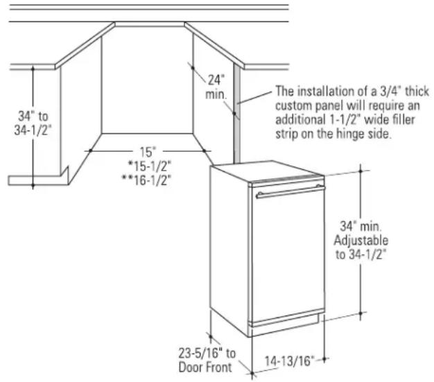
* For flush installation of ZDIS150 and ZDIC150 models: Install a 1/2"-wide filler strip on the hinge side. The filler strip will act as a spacer between the door case and adjacent cabinets and will prevent interference with the cabinet door swing. Recess the filler strip 1" back from the front face of the ice maker, or even with the front edge of the product case. The width of the opening must be 15-1/2" (including the 1/2" filler strip).
** The black model ZDIC150 with a custom panel cannot be installed flush. A 1-1/2"-wide filler strip is required on the hinge side. The ice maker will project forward 3/4" of adjacent cabinets. Recess the filler strip 1-3/4" back from the front face of the ice maker or even with the front edge of the product case. The width of the opening must be 16-1/2" wide, including the 1-1/2" filler strip.
CUTOUT & PRODUCT DIMENSIONS (Cont.)
Cutout dimensions shown allow for a full door swing.
Flush Installation, Top View

Custom Panel Installation, Top View

Corner Installation
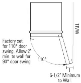
- Not designed for outdoor installation.
- The ice maker must be installed in an area protected from elements such as wind, rain, water spray or drip. The area should be ven ti lat ed with temperatures above 55°F (13°C) and below 110°F (43°C). Best results are obtained between 70°F (21°C) and 90°F (32°C).
- The ice maker may be closed in on the top and three sides as long as the front is un ob structured for air circulation and proper operation.
- Installation should be such that the ice maker can be moved forward for ser vic ing, if necessary.
- The bottom grille on the front must be unobstructed to provide proper air flow.
WATER SUPPLY
A cold water supply with water pressure of between 30 and 120 psi is required to operate the ice maker. If you have questions about your water pressure, call a licensed, qualified plumber.
ELECTRICAL REQUIREMENTS
WARNING: (Please read carefully). FOR PERSONAL SAFETY, THIS APPLIANCE MUST BE PROPERLY GROUNDED. Do not remove ground plug. Do not use an adapter. Do not use an extension cord. Failure to follow these instructions can result in death, fire or electrical shock.
!AVERTISSEMENT :
Before you move your ice maker into its final location, it is important to make sure you have the proper electrical connection:
A 115 volt, 60 Hz., AC only, 15- or 20-amp electrical supply, properly grounded in accordance with the National Electrical Code and local codes and ordinances, is required. Use an outlet which cannot be turned off by a switch or pull chain.
IMPORTANT: This unit must NOT be on a GFCI (Ground Fault Circuit Interrupter) equipped outlet or nuisance tripping may occur resulting in loss of cooling. Ice quality may be affected. If nuisance tripping has occurred, and if the condition of the ice appears poor, dispose of the ice.
Recommended Grounding Method
The ice maker must be grounded. The ice maker is equipped with a power supply cord having a 3 prong grounding plug. The cord must be plugged into a mating, 3 prong, grounding-type wall outlet, grounded in accordance with the National Electrical Code and local codes and ordinances. If a mating wall receptacle is not available, one must be installed by a qualified electrician.
DRAINING REQUIREMENTS
Determine a method of drainage. If a floor drain is to be installed, the drain must be accurately located. The installation of a custom door panel will affect the drain location. See page 7 to determine the exact location of the floor drain, front to back, with or without a custom door panel.
A drain pump kit, ZPK2, is available and will not interfere with placement of the ice maker.
BEFORE YOU BEGIN:
- If a custom panel is to be installed, follow the instructions shown on pages 10 and 11.
-Order ZIP75 (black) panel kit. - Order the custom panel from the cabinet manufacturer.
-Secure the custom panel onto the ice maker. - The door swing is reversible. If desired, change the door swing before installation following instructions on page 13.
- Slide the ice maker into the installation location.
- Open and close the door to be sure there is no interference.
- Check to be sure the ice maker can be moved back into the opening, flush with adjacent cabinetry. There should be no interference with the floor drain.
- Check to be sure the ice maker is level. The ice maker will not operate properly if it is not level. See page 6.
POWER SUPPLY
WARNING: (Please read carefully). FOR PERSONAL SAFETY, THIS APPLIANCE MUST BE PROPERLY GROUNDED. Failure to follow these instructions can result in death, fire or electrical shock.
⚠ AVERTISSEMENT :
Do not use an extension cord or adapter plug with this appliance. Follow National Electrical Code or prevailing local codes and or di nanc es.
This ice maker must be supplied with 115V, 60Hz, and connected to an individual, properly grounded branch circuit, and protected by a 15 or 20 amp circuit breaker or time delay fuse.

Electrical Supply Should Enter From Back Wall In Shaded Area
- A properly grounded three-prong outlet should be located within reach of the ice maker's 66" long power cord. For a built-in installation, locate the receptacle in the shaded area shown.
IMPORTANT: (Please read carefully).
The power cord of this appliance is equipped with a three-prong (grounding) plug that mates with a standard three-prong grounding wall re cep ta cle to minimize the possibility of electric shock. The customer should have the wall receptacle and circuit checked by a qualified electrician to make sure the re cep ta cle is properly ground ed and has the correct polarity.
- Where a standard two-prong wall receptacle is encountered, it is the personal re spon si bil i ty and obligation of the customer to have it replaced with a properly grounded three-prong wall receptacle.
Do not, under any circumstances, cut or remove the third (ground) prong from the power cord. DO NOT USE AN EXTENSION CORD.
REMOVE PACKAGING AND PARTS
- Lay the carton on rear face and break open the bottom flap.
- Set the carton upright with all four bottom flaps outward.
- Lift carton up and off ice maker.
- Remove all tape and packaging material from the outside and inside of the cabinet.
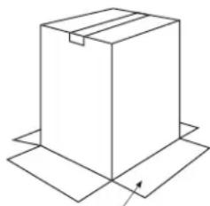
Open Bottom Flaps
WATER FILTRATION SYSTEM
Install Water Filter
- Locate the accessory packet in the ice maker and remove the water filter.
- Remove the cover from the water filter. Be sure the O-rings are still in place after the cover is removed.
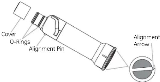
- Locate the water filter compartment on the right-hand side of the ice maker controls.
- Align the alignment pin on the side of the filter with the cutout channel in the control housing and insert filter.
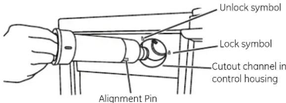
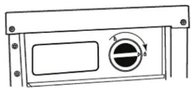
- Turn filter clockwise until it locks into the housing.
NOTE: If the filter is not correctly locked into place, the ice maker will not produce ice.
ADJUST HEIGHT AND LEVEL THE ICE MAKER
Height adjustments may be necessary to install the ice maker below a countertop, and may be accomplished by adjusting both the front and rear leveling legs. The ice maker must be level to operate properly.
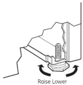
To level and adjust the height:
- With one person holding the ice maker, carefully tilt the machine to access the leveling legs.
- Use an adjustable wrench to turn the legs.
- Turn legs right to lower, turn left to raise the ice maker.
- Check top and side with a level. Continue adjusting legs until the ice maker is level and stable.
WATER SUPPLY SET-UP
- A cold water supply with water pressure between 30 and 120 p.s.i. is required for ice maker operation.
- To allow sufficient water flow to the ice maker, a minimum 1/2" diameter home supply line is recon
- Route GE SmartConnect™ Kit or 1/4" O.D. copper tubing between house cold water line and the water connection location.
- The water line should be long enough to extend to the back of the ice maker when the unit is moved forward for service.
- Install tubing only in areas where temperatures will remain above freezing.
- The water line should be flushed to clear any foreign material before connecting to the ice maker.
NOTE: The only GE approved plastic tubing is supplied in the GE SmartConnect™ Refrigerator Tubing kits. Do not use any other plastic water supply line. The line is under pressure at all times. Other types of plastic may crack or rupture with age and cause water damage to your home. Order parts below at GEApplianceParts.com or by calling 1.800.626.2002. GE SmartConnect™ Refrigerator Tubing Kits are available in the following lengths:
2' (0.6 m) WX08X10002 15' (4.6 m) WX08X10015 6' (1.8 m) WX08X10006 25' (7.6 m) WX08X10025
Tools and Parts Needed:
Gather the required tools and parts before starting installation:
● Flat-blade screwdriver
- 7/16" and 1/2" open-end wrenches or two adjustable wrenches
- 1/4" nut driver
- 1/4" (6.35 mm) soft copper or GE SmartConnect tubing
NOTE: Do not use a piercing-type or 3/16" (4.76 mm) saddle valve which reduces water flow and clogs more easily.
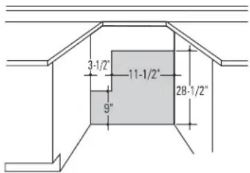
Water Supply Should Enter From Back Wall In Shaded Area
CONNECT WATER SUPPLY TO APPLIANCE
- The water line should be flushed to clear any foreign material before connecting to the ice maker.
- Connect the water line to the water supply tube outside of the rear access cover.
Copper Tubing:
- Use a standard plumbing female connector or union for 1/4" copper tubing that can be purchased locally.
GE SmartConnect™ Tubing:
- Insert the molded end of the tubing into the ice maker connection. Tighten the compression nut until it is just hand tight.
- Tighten one additional turn with a wrench. Over-tightening can cause leaks!
- Make sure there are no sharp bends or kinks that could restrict water flow.
CONNECT WATER LINE
- Turn off main water supply. Turn on nearest faucet to clear water line.
- Install a shut-off valve between the ice maker water valve and cold water pipe. The installation of an easily accessible shut-off valve in the water line is required.
For Copper Tubing:
- Use a squarely cut 1/4" (6.35 mm) soft copper tubing for the cold water supply.

- Ensure you have the proper length of copper wire and that the ends have been cut square.
- Remove and discard the short, black plastic tube, if applicable, from the end of the inlet water tube.
CONNECT WATER LINE (cont.)
For GE SmartConnect™ Tubing:
- Insert the molded end of the tubing into the ice maker connection. Tighten the compression nut until it is just hand tight.
- Tighten one additional turn with a wrench. Over-tightening can cause leaks!
-
Make sure there are no sharp bends or kinks that could restrict water flow.
-
Thread compression nut onto water supply line connector. Tighten nut until finger-tight. Tighten with a wrench two more turns. Do not over-tighten.
NOTE: To avoid rattling, be sure copper tubing does not touch the cabinet's side wall or other parts inside the cabinet.
-
Install water supply tube clamp around water supply line to reduce strain on the coupling.
-
Turn shutoff valve ON.
-
Check for leaks. Tighten any connections (including connections at the valve) or nuts that leak.
REVERSE OSMOSIS WATER SUPPLY
IMPORTANT: The performance of the ice maker may be affected when it is connected to a reverse osmosis system.
- The pressure of the water supply coming out of a reverse osmosis system going to the water inlet valve of the ice maker needs to be between 30 and 120 psi.
- If a reverse osmosis system is connected to your cold water supply, the water pressure to the system must be a minimum of 40 to 60 psi. The reverse osmosis system must provide 1 gal. of water per hour to the ice maker for proper ice maker operation.
- Reverse osmosis water filtration systems can be used only with ice maker installations that have a gravity drain.
- Do not use copper tubing when the ice maker is connected to a reverse osmosis water system.
CONNECT DRAIN
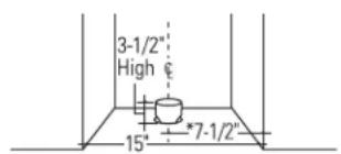
This ice maker is equipped with a gravity drain to prevent water from flowing back into the storage bin and overflowing onto the floor. The ideal installation has a standpipe with a 2" to 1-1/2" PVC drain reducer installed directly below the drain tube:

- A 1" min. physical gap between the bottom of the ice maker drain hose and the top of the house drain is required. See illustration.
-7-1/2"tocenterline of the opening.
-Approximately3-1/2"high. - 22" from the front, or 22-3/4" when installing a 3/4" door panel.
- Drain lines must be at least 5/8" inside diameter.
Locate Standpipe in Exact Center of the Icemaker
*If you have installed a custom panel and the 1-1/2" filler strip, position the drain at the exact center of the product.
NOTE: A drain pump is necessary when a floor drain is not available. Order ZPK2 Drain Pump Kit or contact your local plumber for a recommended pump available in your area.
TEST DRAIN HOSE ALIGNMENT: Before sliding the ice maker into the cabinet opening, check to be sure the bottom of the drain tube is below the rear cover. To test, place a pan below the drain hose. Slowly pour a gallon of water into the ice bin and check to be sure that water does not wet the rear cover.
REVERSE THE DOOR SWING
IMPORTANT: Disconnect power to the ice maker.
Tools Required:
• 1/4" wrench (SS models)
- Torx screwdriver, size 20
- Phillips screwdriver
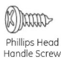
Parts Identification: (For Reference Only)




STEP 1 - REMOVE DOOR
For Black Model:
Remove the handle screws and lift off handle.

For Stainless Steel Model:
- Remove two hex screws each from the bottom of the stainless steel door skin.
- Pull out on the bottom portion of the door skin and lift up to remove.

REVERSE THE DOOR SWING (cont.)
STEP 2 - DOOR STOP AND END-CAP REVERSAL
- Remove the hinge pin from the top hinge.
- Remove the door from the hinges and replace the top hinge pin.

-
Remove the screw and door stop at upper left corner. Remove the screw and end cap at lower right corner. Place the door stop at lower right corner and tighten screw. Place the end cap at upper left corner and tighten screw.
-
Remove the screw and door stop at lower left corner. Remove screw and end cap from upper right corner. Place the door stop at upper right corner and tighten screw. Place the end cap at lower left corner and tighten screw.
-
Set the door aside.
REVERSE THE DOOR SWING (cont.) REVERSE
STEP 3 - REVERSE HINGES
- Unscrew hinge screws and remove the top hinge. Replace screws in empty hinge holes.
- Remove screws from opposite side of ice maker cabinet. Turn top hinge upside down so the hinge pin points up. Place hinge on the bottom opposite side of ice maker and tighten screws.

- Remove original bottom hinge screws and hinge. Replace screws in the empty hinge holes.
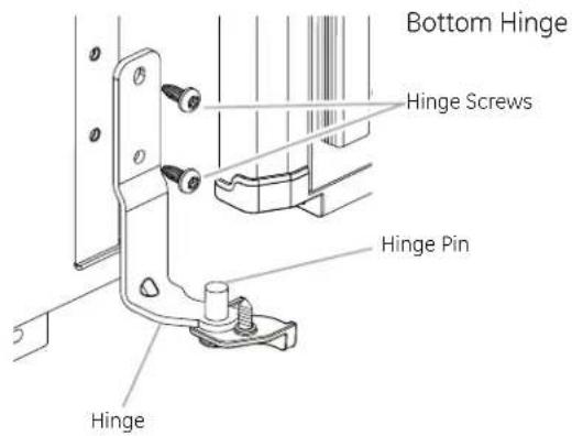
- Remove screws from top of opposite side of ice maker cabinet. Turn hinge upside down so the hinge pin points down. Place hinge on top opposite side of ice maker cabinet and tighten screws.
- Remove the top hinge pin.
THE DOOR SWING (cont.)
STEP 4 - REPLACE DOOR
For Black Model:
Align handle with the holes in the door and replace screws. Tighten.
For Stainless Steel Model:
- Replace the door skin on the door. Start by placing the top of the skin over the top of the door. Slide the sides in behind the side protectors. Line up the bottom of the skin with the two holes on the bottom of the door.
- Replace two hex screws in the bottom of the stainless steel door skin.
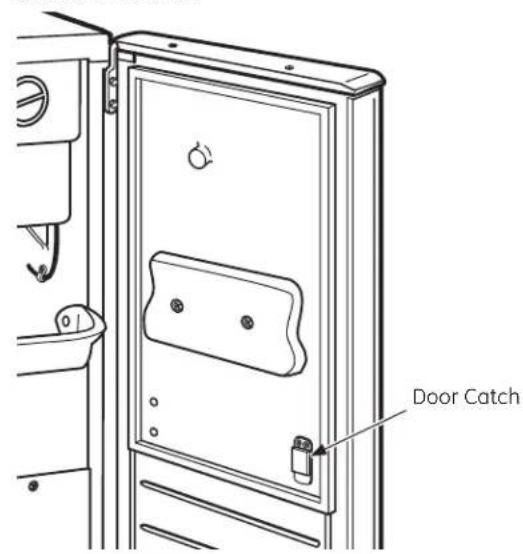
STEP 5 - REVERSE DOOR CATCH
- Remove the plastic screws from the op po site side of the door.
- Remove the metal screws from the mag net ic door catch and reinstall on the op po site side of the door.
- Install the plastic screw into place on the op po site side of the door.
- BEFORE YOU BEGIN:
Read these instructions completely and carefully.
- IMPORTANT:
Save these instructions for local inspector's use.
- IMPORTANT:
Observe all governing codes and ordinances.
- Note to Installer – Be sure to leave these instructions with the Consumer.
- Note to Consumer – Keep these instructions with your Owner's Manual for future reference.
NOTE:
- This auxiliary drain pump is designed to pump water to a maximum height of 10 feet and a maximum horizontal distance of 100 feet.
- To minimize condensation on the drain tube, insulate the full length of the tube from the pump to the drain.

WARNING:
Disconnect electrical power supply to ice maker before installing pump. Failure to do so can result in death, fire, or electrical shock. Replace all panels before operating.

AVERTISSEMENT :
- Auxiliary drain pump
- Drain tube, 5/8" ID x 5-1/8" (bin to pump reservoir inlet)
- Drain tube, 1/2" ID × 10' (pump check valve to house drain)
- Vent tube, 5/16" ID x 32" (pump reservoir vent to cabinet back)
- 3 cable clamps (secures vent tube to back of product)
- 5 screws, #8 - 32 x 3/8" (secures pump to baseplate and clamps to back of ice maker)
- Small hose clamp 5/8" (secrees vent and drain tube to pump)
- 3 large adjustable hose clamps 7/8" (secure drain tube to bin and auxiliary drain pump reservoir inlet) secure hose drain to pump
- 2 rear covers
• Installation Instruction Sheet - 1 zip tie
STEP 1 - REMOVE ORIGINAL PARTS
NOTE: If pump is being installed on a ice maker that has not been completely installed, please proceed to Drain Pump Install section.
- Unplug power cord from rear cover.
- Remove screws holding the rear cover. Retain screws. Carefully pull rear cover away from drain tube.
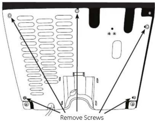
- Remove old drain tube and clamp attached to bin. Discard the tube and clamp.

STEP 2 - CONNECT ELECTRICAL
- Position pump at the right side, just outside of the opening.
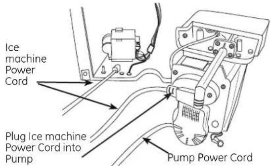
- Plug the ice machine power cord into the front of the pump.
STEP 3 -INSTALL NEW TUBING
- Attach vent tube to pump with new 5/8" hose clamp. Attach drain tube from bin to pump with 7/8" hose clamp.
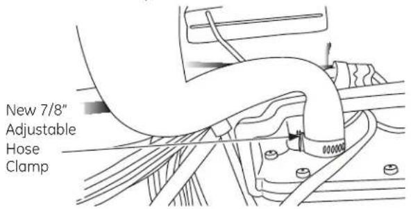
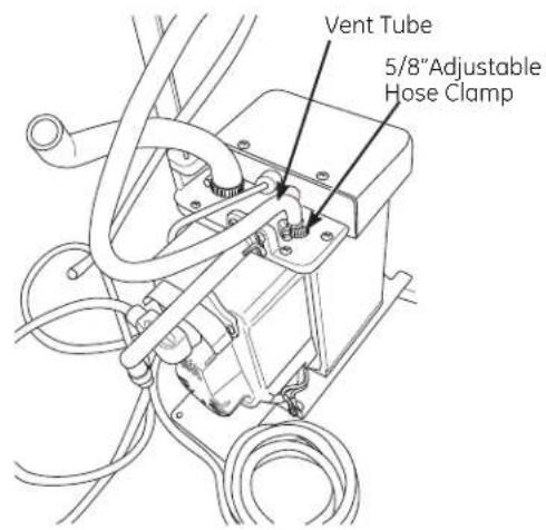
- Coil ice machine power cord into a 4" dia. coil and secure with electrical tape. Place the coil onto the top of the pump.
STEP 4 - INSERT DRAIN PUMP
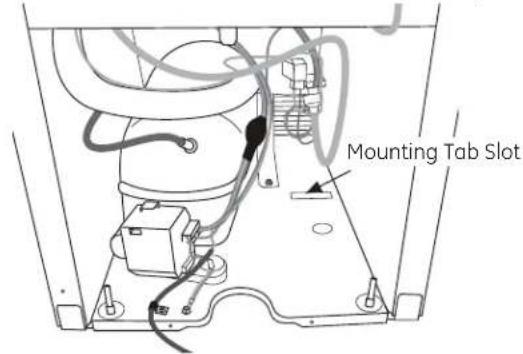
- Carefully slide the auxiliary drain pump into the bottom of the ice machine. The tab on the back of the pump should slip into the rectangular slot on the ice machine floor. It may be necessary to tip the pump slightly to engage the tab.
NOTE: The pump must be in position before connecting the bin drain tube. Slide pump tab into floor slot in the bottom of the cabinet. See Step 5.
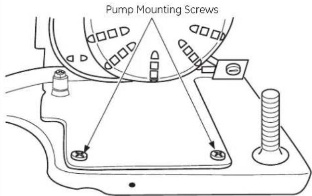
- Secure the pump to the base with the 2 supplied screws.
STEP 5 - INSTALL BIN DRAIN TUBE
Install the new drain tube with the new 7/8" clamps.

STEP 6 - SECURE VENT TUBE
- Place rear cover against the back of the ice machine. Route the vent tube, power cord, drain tube, and water supply line through cut outs in the rear cover.

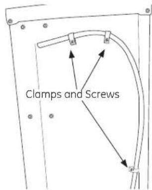
- Secure rear cover with original screws. Attach vent tube to unit with clamps as shown.
-
Trim one end of hose at 3/4" diameter. Secure 5/8" diameter section to pump with 7/8" adjustable hose clamp
-
Route drain tube to house drain.
NOTE: While performing installations described in this book, safety glasses or goggles should be worn.
NOTE: Product improvement is a continuing endeavor at General Electric. Therefore, materials, appearance and specifications are subject to change without notice.
- BEFORE YOU BEGIN:
Read these instructions completely and carefully. - IMPORTANT:
Save these instructions for local inspector's use. - IMPORTANT:
Observe all governing codes and ordinances. - Note to Installer – Be sure to leave these instructions with the Consumer.
- Note to Consumer – Keep these instructions with your Owner's Manual for future reference.
WARNING:
Disconnect electrical power supply to ice maker before installing front panel. Failure to do so can result in death, fire, or electrical shock. Do not operate ice maker while installing panel.
▲ AVERTISSEMENT :
- 2 side trim pieces
- 8 side trim screws
- Door handle
Tools and Materials Required:
- 8 #6 flat head wood screws, 1/2" long
- Drill and 1/8" bit
- Safety glasses
- Tape
- Custom panel
NOTE: If installing a 3/4" trimless custom panel, a 1-1/2" wide filler strip may be required. The filler strip will act as a spacer between the ice maker case and the adjacent cabinet, and will prevent interference with the ice maker door swing when it is installed between frameless or framed cabinetry. The width of the cutout opening must include the width of the filler strip. The product cannot be installed flush to adjacent 24" deep cabinets with a 3/4" thick custom panel.
This kit contains a new handle and two side mounting brackets to support a trimless custom door panel up to 3/4" thick. A custom handle may replace the supplied handle.
IMPORTANT:
- Cut edges of the custom door panel will be seen and must be finished for best ap pear ance. The back side of the panel should be finished a minimum of 1/2" on all sides.
- The custom panel, both raised and flat design, should be con struct ed in the same manner as typical cabinet doors.
- Order the custom panel from the cabinet manufacturer. Be sure to provide the exact dimensions so that the panel is con structured accurately.
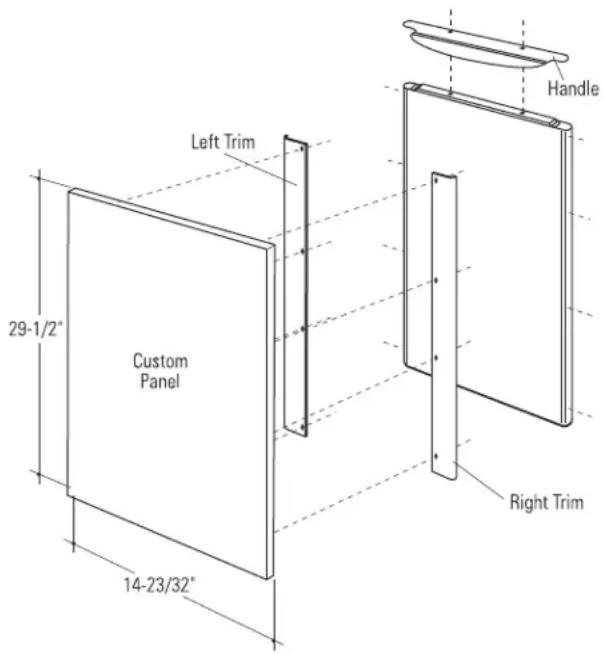
STEP 1 DISCONNECT POWER TO THE ICE MACHINE
STEP 2 REMOVE HANDLE AND NAMEPLATE
- Remove the door handle by removing the two top mounting screws. Set screws aside. Discard handle.
- The Monogram nameplate is held in place with adhesive. Remove the nameplate.
STEP 3 MARK MOUNTING SCREW LOCATIONS
- Align and hold the side trim pieces against the ice maker door and mark screw locations on the sides.
- Drill 1/8" pilot holes into the door sides of the ice maker.
STEP 4 SECURE CUSTOM HANDLE TO CUSTOM PANEL. (SKIP THIS STEP IF YOU ARE USING THE SUPPLIED HANDLE)
- A custom handle can be installed onto the 3/4" thick panel, replacing the supplied handle.
- The custom handle can be installed at the top or side of the panel.
- Drill pilot holes through the front of the custom panel to match the chosen handle.
- Secure the handle to the panel with flat head wood screws.
- Replace original handle screws in the top of the door frame.
STEP 5 SECURE SIDE TRIM PIECES TO CUSTOM PANEL
- Lay the custom panel appearance-side-down on a clean surface.
- Align top and bottom side trim to the custom panel sides.
- Tape the side trim pieces to the back of the custom panel.
- Place the panel with trim against the door to be sure that trim and panel fits the door side to side and top to bottom. Adjust as needed.
- Mark screw locations and remove trim. Drill pilot holes.
- Install side trim to the back side of the custom panel with screws (not supplied). Use flat head wood screws 1/2" long.
STEP 6 INSTALL ASSEMBLED PANEL ONTO THE ICE MACHINE
Install panel to ice maker with supplied screws, four on each side.
STEP 7 INSTALLSUPPLIED DOOR HANDLE (IF USED)
Install the new supplied handle with original screws.
Notes
NOTE: While performing installations described in this book, safety glasses or goggles should be worn.
For Monogram® local service in your area, call 1.800.444.1845.
NOTE: Product improvement is a continuing endeavor at General Electric. Therefore, materials, appearance and specifications are subject to change without notice.
Pub. No. 31-49006-1
Part No. 245D1420P001
W10136140A 07-13 GE
Printed in the United States

GE Appliances & Lighting
Appliances
General Electric Company
Louisville, KY 40225
GEAppliances.com

- INSTALLATION INSTRUCTIONS
- BEFORE YOU BEGIN
- IMPORTANT
- WARNING
- ⚠ AVERTISSEMENT
- CONTENTS
- DESIGN INFORMATION
- INSTALLATION
- ACCESSORIES
- MODELS AVAILABLE
- OPTIONAL ACCESSORIES
- TOOLS AND MATERIALS REQUIRED FOR BASIC INSTALLATION
- ADVANCE PLANNING
- CUTOUT & PRODUCT DIMENSIONS (CONT.)
- WATER SUPPLY
- ELECTRICAL REQUIREMENTS
- AVERTISSEMENT
- RECOMMENDED GROUNDING METHOD
- DRAINING REQUIREMENTS
- POWER SUPPLY
- IMPORTANT: (PLEASE READ CAREFULLY)
- REMOVE PACKAGING AND PARTS
- WATER FILTRATION SYSTEM
- INSTALL WATER FILTER
- ADJUST HEIGHT AND LEVEL THE ICE MAKER
- TO LEVEL AND ADJUST THE HEIGHT
- WATER SUPPLY SET-UP
- TOOLS AND PARTS NEEDED
- CONNECT WATER SUPPLY TO APPLIANCE
- COPPER TUBING
- GE SMARTCONNECT™ TUBING
- CONNECT WATER LINE
- FOR COPPER TUBING
- CONNECT WATER LINE (CONT.)
- FOR GE SMARTCONNECT™ TUBING
- REVERSE OSMOSIS WATER SUPPLY
- CONNECT DRAIN
- REVERSE THE DOOR SWING
- IMPORTANT: DISCONNECT POWER TO THE ICE MAKER
- TOOLS REQUIRED
- PARTS IDENTIFICATION: (FOR REFERENCE ONLY)
- STEP 1 - REMOVE DOOR
- FOR BLACK MODEL
- FOR STAINLESS STEEL MODEL
- REVERSE THE DOOR SWING (CONT.)
- STEP 2 - DOOR STOP AND END-CAP REVERSAL
- REVERSE THE DOOR SWING (CONT.) REVERSE
- STEP 3 - REVERSE HINGES
- THE DOOR SWING (CONT.)
- STEP 4 - REPLACE DOOR
- STEP 5 - REVERSE DOOR CATCH
- NOTE
- STEP 1 - REMOVE ORIGINAL PARTS
- STEP 2 - CONNECT ELECTRICAL
- STEP 3 -INSTALL NEW TUBING
- STEP 4 - INSERT DRAIN PUMP
- STEP 5 - INSTALL BIN DRAIN TUBE
- STEP 6 - SECURE VENT TUBE
- ▲ AVERTISSEMENT
- TOOLS AND MATERIALS REQUIRED
- STEP 1 DISCONNECT POWER TO THE ICE MACHINE
- STEP 2 REMOVE HANDLE AND NAMEPLATE
- STEP 3 MARK MOUNTING SCREW LOCATIONS
- STEP 4 SECURE CUSTOM HANDLE TO CUSTOM PANEL. (SKIP THIS STEP IF YOU ARE USING THE SUPPLIED HANDLE)
- STEP 5 SECURE SIDE TRIM PIECES TO CUSTOM PANEL
- STEP 6 INSTALL ASSEMBLED PANEL ONTO THE ICE MACHINE
- STEP 7 INSTALLSUPPLIED DOOR HANDLE (IF USED)
- NOTES
Brand : GE
Model : ZDIS150ZSS
Category : Sorbet maker