Splendor Pro (2013) - Motorcycle HERO - Free user manual and instructions
Find the device manual for free Splendor Pro (2013) HERO in PDF.


| Product Type | Motorcycle |
| Brand | Hero |
| Model | Splendor Pro |
| Year | 2013 |
| Engine Displacement | 97.2 cc |
| Maximum Power | 8.2 bhp @ 8000 rpm |
| Maximum Torque | 8.05 Nm @ 5000 rpm |
| Fuel System | Carburetor |
| Transmission | 4-speed manual |
| Front Suspension | Telescopic fork |
| Rear Suspension | Swingarm with dual shock absorbers |
| Front Brake | Drum, 130 mm |
| Rear Brake | Drum, 130 mm |
| Overall Length | 2010 mm |
| Overall Width | 720 mm |
| Overall Height | 1080 mm |
| Wheelbase | 1275 mm |
| Kerb Weight | 110 kg |
| Fuel Tank Capacity | 10.0 L |
| Ignition | CDI |
| Starting System | Kick start |
| Battery | 12V, 4 Ah |
| Tyre Size (Front) | 2.75-18 |
| Tyre Size (Rear) | 3.00-18 |
Frequently Asked Questions - Splendor Pro (2013) HERO
User questions about Splendor Pro (2013) HERO
0 question about this device. Answer the ones you know or ask your own.
Ask a new question about this device
Download the instructions for your Motorcycle in PDF format for free! Find your manual Splendor Pro (2013) - HERO and take your electronic device back in hand. On this page are published all the documents necessary for the use of your device. Splendor Pro (2013) by HERO.
USER MANUAL Splendor Pro (2013) HERO
Thank you for selecting a Hero MotoCorp Splendor Pro. We wish you many miles of continued riding pleasure in the years ahead.
We, at Hero MotoCorp, are committed to demonstrate excellence in our environment performance on a continual basis, as an intrinsic element of our corporate philosophy. To achieve this we commit ourselves to continue product innovations to improve environment compatibility, comply with all applicable legislation including environment legislation and strengthen the green supply chain.
Your motorcycle is conforming to latest (Bharat Stage-III norms) regulation for emission, safety & noise levels. We are also using non asbestos brake shoes and engine gaskets which are environment friendly in nature.
This booklet is your guide to the basic operation and maintenance of your new Hero MotoCorp Splendor Pro. Please take time to read it carefully. As with any fine machine, proper care and maintenance are essential for trouble-free operation and optimum performance.
Your Authorised Hero MotoCorp dealer will be glad to provide further information or assistance and is equipped to handle your future service needs.
Let us make this world a safer, healthier and more environment friendly place.
NOTE
ALL INFORMATION, ILLUSTRATION, PHOTOGRAPH, DIRECTIONS, SPECIFICATIONS AND OTHER CONTENTS COVERED IN THIS OWNER'S MANUAL ARE BASED ON THE LATEST PRODUCT INFORMATION AVAILABLE AT THE TIME OF ITS PRINTING APPROVAL, AND THE ACCURACY OR CORRECTNESS OF THE SAME IS NOT UNDERTAKEN OR GUARANTEED. Hero MotoCorp Limited. RESERVES THE RIGHT TO MAKE CHANGES IN ITS CONTENTS AT ANY TIME WITHOUT NOTICE AND/OR INCURRING ANY OBLIGATION, WHATSOEVER. NO ONE IS ALLOWED TO REPRODUCE ANY PART OF THIS PUBLICATION WITHOUT OBTAINING PRIOR WRITTEN PERMISSION FROM Hero MotoCorp Limited.
CONTENTS
| Pg. No. | Pg. No. | ||
| MOTORCYCLE IDENTIFICATION | 1 | MAINTENANCE SCHEDULE | 28 |
| PRODUCT SPECIFICATION | 2 | OIL SCREEN FILTER/ CENTRIFUGAL FILTER | 30 |
| SAFE RIDING TIPS | 4 | SPARK PLUG | 31 |
| ACCESSORIES AND MODIFICATIONS | 5 | AIR CLEANER | 32 |
| TIPS FOR HEALTHY ENVIRONMENT | 6 | THROTTLE OPERATION | 34 |
| DESCRIPTION | 7 | VALVE CLEARANCE | 34 |
| PARTS FUNCTION | 10 | CARBURETOR | 36 |
| INSTRUMENTS & INDICATORS | 10 | CLUTCH | 36 |
| IGNITION SWITCH | 11 | DRIVE CHAIN | 38 |
| LEFT HANDLE BAR CONTROLS | 12 | FRONT BRAKE | 40 |
| STARTER SWITCH | 13 | REAR BRAKE | 41 |
| CLUTCH SWITCH | 13 | 42BRAKE | |
| STEERING LOCK | 13 | BATTERY | 43 |
| HELMET LOCK | 14 | 45FUSE RI | |
| SIDE STAND INDICATOR/ SIDE STAND SWITCH | 14 | 45STOP LA | |
| FUEL VALVE | 15 | 46SIDE ST | |
| FUEL TANK | 16 | 47HEADLA | |
| ENGINE OIL | 17 | SUSPENSION | 47 |
| ENGINE OIL TOP UP PROCESS | 17 | FRONT WHEEL REMOVAL | 48 |
| ENGINE OIL REPLACEMENT PROCESS | 18 | REAR WHEEL REMOVAL | 49 |
| TYRES | 19 | WASHING THE MOTORCYCLE | 50 |
| PRE-RIDE INSPECTION | 21 | CATALYTIC CONVERTER | 50 |
| STARTING THE ENGINE | 22 | AIR SUCTION VALVE | 51 |
| RIDING | 23 | BASIC TROUBLE SHOOTING | 52 |
| BRAKING / PARKING | 24 | ROAD SIGNS | 55 |
| ANTI THEFT TIPS | 25 | DELIVERY CERTIFICATE | |
| UTILITY BOX | 25 | WARRANTY | |
| TOOL KIT / FIRST AID KIT | 26 | FREE SERVICE COUPONS | |
| SAFETY PRECAUTIONS | 27 | SERVICE RECORD SHEET | |
| MAINTENANCE | 28 | SERVICE ADVICE SHEET | |
| OWNERSHIP RECORD & DATA |
MOTORCYCLE IDENTIFICATION
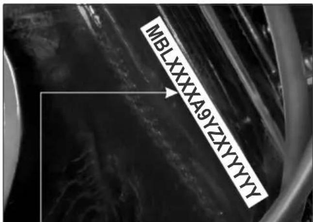
Vehicle Identification Number (VIN)
Location : Stamped on the right side of the steering head tube.
VIN: MBLXXXXA9YZXYYYYYY
| MBLManufacturerCode | XXXXA9VehicleDescription | YYear ofMfg. | ZAssemblyPlant | XMonth ofMfg. | YYYYYSerialNumber |
Model Code.:
| Model Engine | VIN | |
| Splendor Pro (Electric Start / Drum / Cast Wheel) | A9 EL |
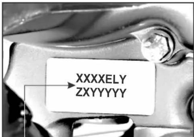
Engine No.
Location: Stamped on the lower side of the left crankcase.
Engine No.: XXXXELYZXYYYYY
| XXXXELEngineDescription | YYear ofMfg. | ZAssemblyPlant | XMonth ofMfg. | YYYYYSerialNumber |
VIN and Engine No. may be required:
- During registration of the motorcycle.
- For dealing with Legal & Insurance Departments.
PRODUCT SPECIFICATION
| ITEM SPECIFICATIONS | |
| DIMENSIONS | |
| Overall Length | 2000 mm |
| Overall Width | 720 mm |
| Overall Height | 1040 mm |
| Wheelbase | 1230 mm |
| 785 mmSaddle Height | |
| Ground Clearance | 159 mm |
| WEIGHT | |
| Kerb Weight | 112 kg |
| CAPACITIES | |
| Engine Oil | 0.95 litre at disassembly |
| 0.75 litre at draining | |
| Fuel Tank | 11.0 litres (minimum) |
| Fuel Reserve Capacity | 1.4 litres (usable) |
| Front Fork Oil | 163 ml |
| ENGINE | |
| Power | 5.74 kW (7.8 Ps) @ 7500 r/min |
| Bore and Stroke | 50.0 x 49.5 mm |
| Compression Ratio | 9.0 :1 |
| Displacement | 97.2 cc |
| Spark Plug | NGK-CR7HSA, BOSCH-UR4AC, Champion-P-RZ9HC (Federal Mogul) |
| Spark Plug Gap | 0.6 - 0.7 mm |
| Valve Clearance (cold) | IN : 0.10 mm EX : 0.10 mm |
| Idle Speed | 1400 ± 100 r/min |
| CHASSIS AND SUSPENSIONFront Suspension Telescopic Hydraulic Shock AbsorbersRear SuspensionCasterTrail lengthTyre size, frontTyre size, rearFront Brake/ Rear Brake Drum TypeFront WheelRear Wheel | Swing Arm with 5 step adjustable Hydraulic Shock Absorber 26^0 80 mm2.75 x 18 - 42P / 4 PR2.75 x 18 - 48P / 6 PRDia 130 mm/ 110 mmCast WheelCast Wheel |
| POWER TRANSMISSIONPrimary reductionFinal reductionGear ratio, 1st2nd3rd4th | 3.722 (67/18)3.071 (43/14)3.182 (35/11)1.706 (29/17)1.238 (26/21)0.958 (23/24) |
| ELECTRICALBatteryAlternatorStarting SystemHead lamp (High/Low)Tail/Stop lampTurn signal lampsMeter IlluminationNeutral indicatorTurn signal indicatorPosition lampHi Beam IndicatorSide Stand Indicator | **MF Battery, MF-4:12V 3 Ah120 WElectric start12V 35/35W Halogen Bulb -MFR*12V 5/10W MFR*12V 10Wx4 (Amber bulb) with clear lens-MFR*12V 1.7Wx212V 1.7W12V 3.0W x 212V 3.0W12V 1.7W12V 1.7W |
| FUSE | 10 A, 15 A |
SAFE RIDING TIPS
Do's:
- Always conduct simple pre-ride inspections (ref. page no 21).
- Always wear a helmet (ISI marked) with chinstrap securely fastened and insist on a helmet for your pillion rider.
- While riding, sit in a comfortable position with your legs close to fuel tank.
- Ride defensively and at a steady speed (between 40 to 50 km/hr).
- For stopping motorcycle, use both brakes simultaneously, keeping throttle in the close position.
- Respect road signs and obey traffic rules for your own safety and that of others on the road (ref. page no. 55 & 56).
- During night time, dip headlamps of your motorcycle for oncoming traffic, or when following another vehicle.
- Give way to others on the road and signal before you make a turn.
- To make yourself more visible, wear bright reflective clothing that fits well.
- Take care of loose / hanging clothes while solo / pillion riding.
- Get your motorcycle serviced regularly by the Authorised Hero MotoCorp workshop.
Hero RideSafe
Don't:
- Never use cell phone while riding the motorcycle.
- Avoid sudden acceleration, braking and turning of your motorcycle.
- Never shift gears without disengaging the clutch and closing the throttle.
- Never touch any part of the hot exhaust system like muffler.
- Never ride under the influence of alcohol or drugs.
- Concentrate on the road and avoid talking to the pillion rider or others on the road.
- Do not litter the road.
- Do not cross the continuous white/yellow line in the centre of the road, while overtaking.
- Do not attach large or heavy items to the handlebars, front forks, or fenders.
- Never take your hands off the steering op. handle while riding.
ACCESSORIES & MODIFICATIONS
Modifying your motorcycle or using non-Hero MotoCorp accessories can make your motorcycle unsafe. Before you consider making any modifications or adding an accessory, be sure to read the following information.
WARNING
Improper accessories or modifications can cause a crash in which you can be seriously hurt or killed.
Follow all instructions in this owner's manual regarding accessories and modifications.
Accessories
- Make sure that the accessory does not obscure any lamps, reduce ground clearance, limit suspension travel or steering travel, affect your riding position or interfere with operating any controls.
- Be sure electrical equipment does not exceed the motorcycle's electrical system capacity (page 3). A blown fuse can cause a loss of lights.
- Do not pull a trailer or sidecar with your motorcycle. This motorcycle was not designed for these attachments, and their use can seriously impair your motorcycle's handling.
Modifications
We strongly advise you not to remove any original equipment or modify your motorcycle in any way that would change its design or operation. Such changes could seriously impair your motorcycle's handling, stability and braking, making it unsafe to ride.
Removing or modifying your lamps, mufflers, emission control system or other equipment can also make your motorcycle illegal.
TIPS FOR HEALTHY ENVIRONMENT
The following tips shall ensure a healthy motorcycle, healthy environment, and a healthy you
- Healthy engine: The engine is the lifeline of every vehicle. To keep it healthy, it should be tuned regularly, which will also help reduce pollution and improve vehicle performance & fuel efficiency.
- Regular Servicing: Get your motorcycle serviced at an Authorised Hero MotoCorp workshop, as per the service schedule, for an optimum performance and keep the emission level under check.
- Genuine Spares: Always insist on Hero MotoCorp genuine parts as spurious or incompatible spares and accessories can upset or deteriorate your motorcycle's running condition.
- Genuine Engine Oil: Hero 4T Plus SAE 10W 30 SL grade (JASO MA2) engine oil recommended by Hero MotoCorp and make sure you change it every 6000 kms. (with top up every 3000 kilometres) to keep the engine fit and environment healthy.
- Noise Pollution: Noise beyond a certain decibel is pollution. Whether it is from horns or defective mufflers., excessive noise will cause headaches and discomfort.
- Emission Pollution: Get emission of your motorcycle checked by Authorised agencies atleast once every 3 months or as notified by the government from time to time.
- Fuel saving & reduce pollution: Switch "OFF" the engine while waiting at traffic signal points to save fuel and reduce pollution, if the waiting period is long.
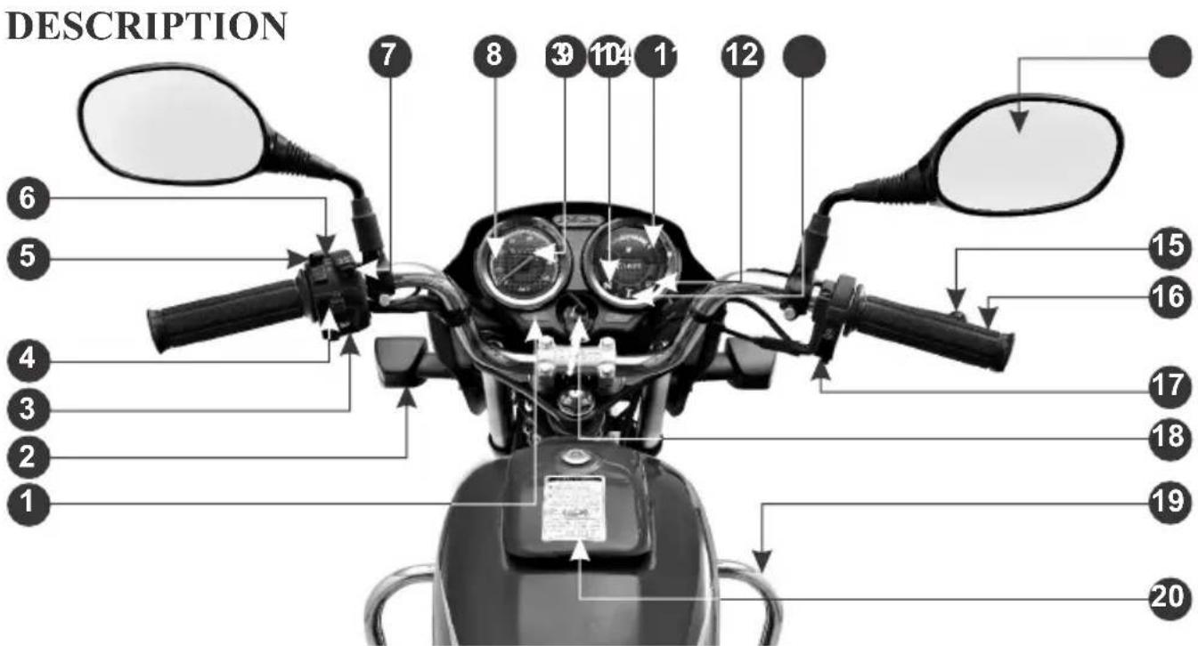
PARTS LOCATION
(1) Turn signal indicator
(2) Front turn signal lamp
(3) Horn switch
(4) Turn signal switch
(5) Headlamp switch
(6) Passing switch
(7) Dimmer switch
(8) Speedometer
(9) Odometer
(10) Neutral indicator
(11) Fuel gauge
(12) High beam indicator
(13) Side stand indicator
(14) Rear view mirror
(15) Front brake lever
(16) Throttle grip
(17) Electric starter switch
(18) Ignition switch with steering lock
(19) Leg guard
(20) Fuel tank lid
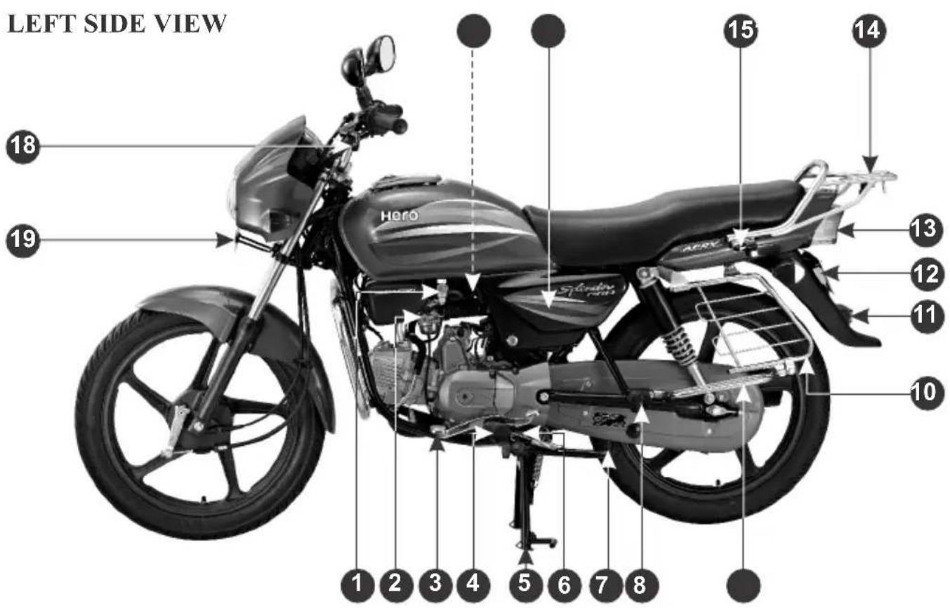
(1) Fuel valve
(2) Carburetor
(3) Gear shift pedal
(4) Rider foot rest
(5) Main stand
(6) Side stand switch
(7) Side stand
(8) Pillion foot rest
(9) Women pillion step
(10) Saree guard
(11) Reflex reflector
(12) Rear number plate
(13) Tail/Stop lamp
(14) Rear carrier
(15) Helmet lock
(16) Left side cover
(17) Air suction valve
(18) Clutch lever
(19) Front number plate
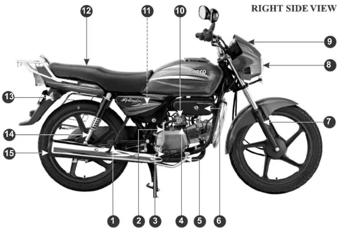
(1) Pillion foot rest
(2) Kick start pedal
(3) Rider foot rest
(4) Oil level dipstick
(5) Rear brake pedal
(6) Utility box
(7) Front suspension
(8) Headlamp
(9) Front visor
(10) Starter motor
(11) Battery compartment ( inside)
(12) Seat
(13) Re ar turn signal lamp
(14) Rear suspension
(15) Exhaust muffler
PARTS FUNCTION
INSTRUMENTS AND INDICATORS
The indicators are in the speedometer panel above the headlamp. The functions are as below.
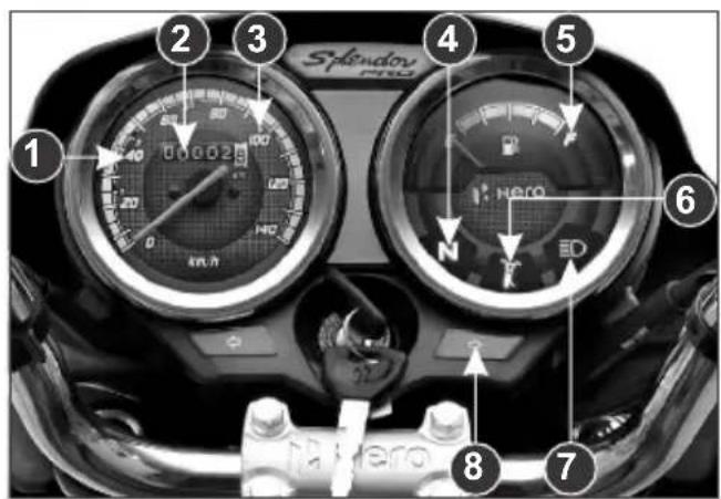
| Sl. No. | Description | Function |
| (1) Speedometer Indicates driving speed | ||
| (2) Odometer Shows accumulated mileage | ||
| (3) Gear shifting Maximum operating speed in each gear. | ||
| (4) Neutral indicator Light glows when vehicle is in neutral | ||
| (5) Fuel gauge Indicates approximate fuel quantity | ||
| (6) Side stand indicator Light glows when the vehicle is parked on the side stand | ||
| (7) High beam indicator Light glows when headlamp is in Hi Beam | ||
| (8) Turn signal indicator Flashes when turn signal switch is operated | ||
IGNITION SWITCH
flowchart
graph TD
    A[""ON" Position"] --> B["Central Node"]
    C[""OFF" Position / Lock Open"] --> B
    D[""LOCK" Position"] --> B
    B --> E["Curved Arrow to Center"]
    style A fill:#000,stroke:#000,color:#fff
    style C fill:#000,stroke:#000,color:#fff
    style D fill:#000,stroke:#000,color:#fff
    style E fill:#000,stroke:#000,color:#fff
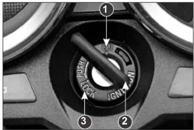
- Ignition switch
- Ignition key
- Steering lock position
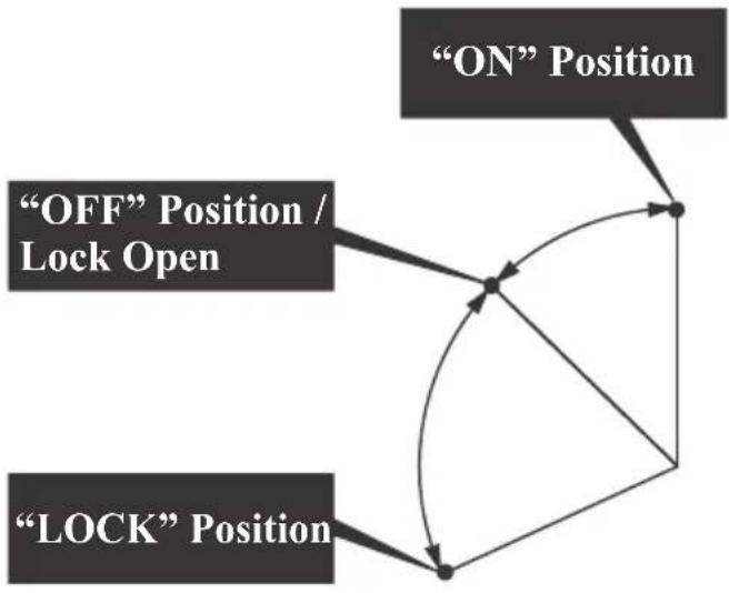
| Key Position | Function | Key Removal |
| “ON” | The engine can be started, Turn signal lamps, Horn, Tail/Stop lamp, Fuel Gauge and Pass Lamp will be functional | Key cannot be removed |
| “OFF” | Engine cannot be started and no electrical system will be functional. | Key can be removed |
| “LOCK” | Steering can be locked | Key can be removed |
LEFT HANDLEBAR CONTROLS
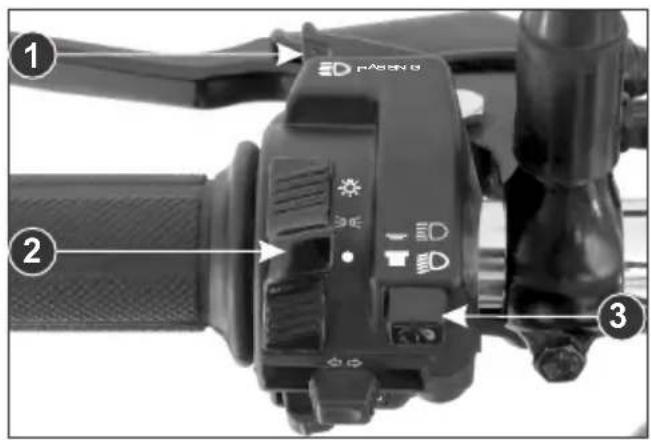
1. Passing switch
Gives an indication for passing ahead.
Functions in DC when the passing switch knob is pressed in the following condition.
-
Headlamp switch is "OFF".
-
Headlamp switch is "ON" but on low beam.
2. Headlamp switch
The switch has three position.
“☀️”, “💡” and “○” marked by white dot.
| Position | Action |
| “OFF” | |
| Following is “ON”• Position lamp• Tail/Stop lamp• Fuel gauge lamp• Speedometer lamp | |
| Head lamp “ON” |
3. Dimmer switch
Select “☐” for high beam and “☐” for low beam.
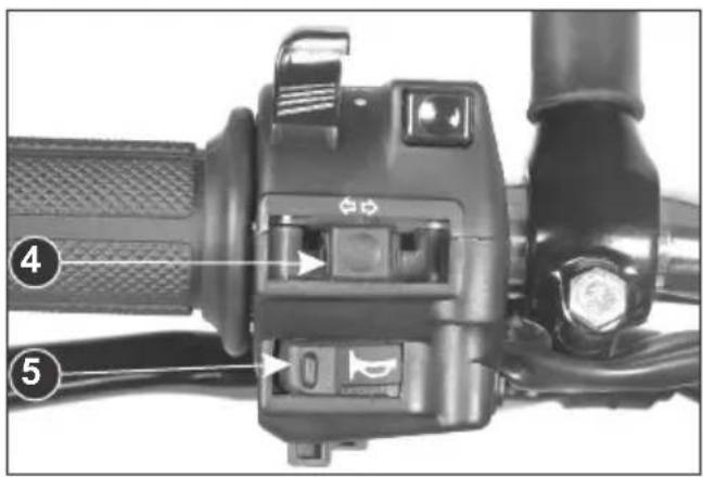
4. Turn signal lamp switch
Shift the turn signal knob sideways for right/left indications and leave it to come back to its normal position on its own.
IMPORTANT : To switch "OFF" the turn signal lamp after completing the turn, gently push the knob inside.
5. Horn switch
Press the switch to operate the horn.
STARTER SWITCH
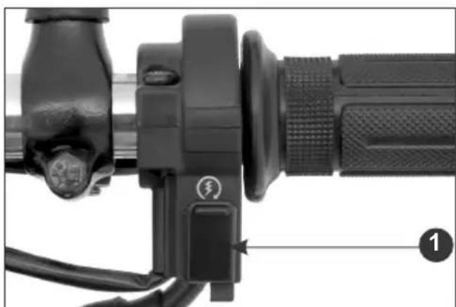
Ensure starter switch (1) is operated when the vehicle is in neutral gear. If the vehicle is engaged in gear press the clutch lever before operating the starter switch. Release starter switch after the engine has started.
CLUTCH SWITCH
There is a clutch switch provided for the safety of the rider. The motorcycle cannot be started by electric starter switch until the clutch lever is operated when the vehicle is engaged in gear.
natural_image
Close-up of a black automotive brake lever with adjustment knob and cable (no visible text or symbols)(1) Electric starter switch
CAUTION
Never hold starter switch continuously for more than 10 seconds as continuous cranking of engine will drain the battery.
STEERING LOCK
Steering lock with Ignition switch, put the key (2) to "OFF" position & turn the handle bar towards left or right & push the key downwards & turn towards "Lock" position. After locking take out the key.
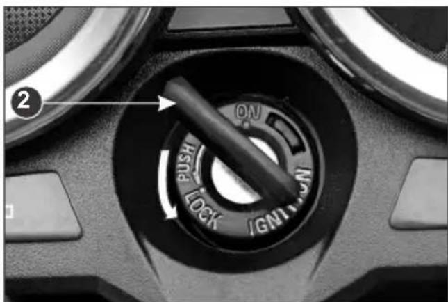
(2) Ignition key
HELMET LOCK
To open lock (1), insert key and turn it anti-clockwise. To lock, push knob (2) all the way inside.
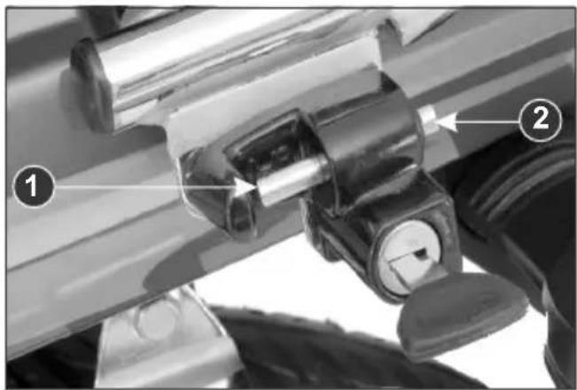
(1) Helmet lock
(2) Knob
SIDE STAND INDICATOR
For the safety of the customer a side stand indicator (1) is provided.
When the vehicle is parked on side stand (Ignition Switch "ON"), an indicator lamp glows in the speedometer panel.
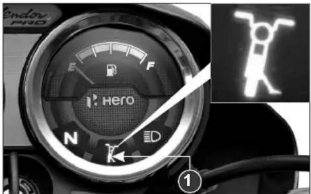
(1) Side stand indicator
SIDE STAND SWITCH
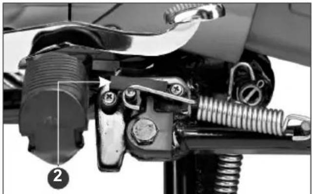
A side stand switch (2) is provided in the side stand, when the vehicle is parked on side stand (Ignition Switch "ON"), the switch enables the side stand indicator lamp to glow on the speedometer panel.
natural_image
Mechanical assembly diagram showing a motor and spring assembly (no text or symbols visible)(2) Side stand switch
FUEL VALVE
The three way fuel valve is on the left side of the carburetor.
OFF
At “OFF”, fuel cannot flow from the tank to the carburetor. Turn the valve “OFF” whenever the motorcycle is not in use.
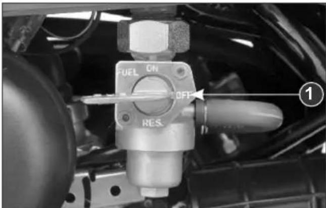
(1) "OFF" Position
ON
At “ON”, fuel will flow from fuel tank to the carburetor.
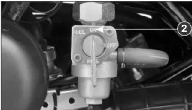
(2) "ON" Position
RES
At “RES”, fuel will flow from the reserve fuel supply to the carburetor. Use the reserve fuel only when the main supply is exhausted. Refill the tank as soon as possible after switching to “RES”. The reserve fuel supply is 1.4 litres (usable).
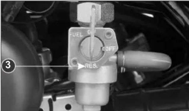
(3) "RES" Position
NOTE
- Do not operate the motorcycle with the fuel valve in the “RES” position after refilling. You may run out of fuel, with no reserve.
- Do not keep the fuel valve between "ON" and "OFF" position while riding, since this may drain reserve fuel from the Tank.
FUEL TANK
Fuel tank capacity is 11 litres (minimum) including reserve supply of 1.4 litres (usable)
- To remove the fuel tank cap (1), insert the ignition key (2), turn it anti-clockwise and lift the lid (3) as shown in the picture.
- Remove the cap by turning it anticlockwise.
- Do not overfill the tank. There should be no fuel in the filler neck (4).
- For locking, press the lid gently and turn the key clockwise.
CAUTION
Do not park the motorcycle under direct sunlight as it causes evaporation of petrol due to heat and deterioration of paint gloss due to ultra violet rays.
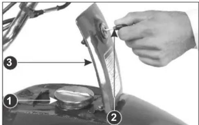
(1) Fuel tank cap
(2) Ignition key
(3) Lid
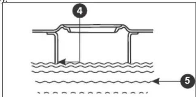
(4) Filler Neck
(5) Fuel
WARNING
Petrol is extremely flammable and is explosive under certain conditions. Refill in a well ventilated area with the engine stopped. Do not smoke or allow flames or sparks in the area where the petrol is refilled or where petrol is stored.
ENGINE OIL
Use hero genuine engine oil or recommended grade oil.
BRAND: Hero 4T plus GRADE: SAE 10W 30 SL Grade (JASO MA2).
Manufactured by :
-
Tide Water Oil Co. (India) Ltd.
-
Savita Oil Technologies Limited.
-
Bharat Petroleum Corporation Limited.
OIL CAPACITY : 0.95 litre
ENGINE OIL LEVEL CHECK
Check engine oil level each day before operating the motorcycle.
The oil level dipstick (1) is on the right crankcase cover for measuring oil level. Oil level must be maintained between the upper (2) and lower (3) level marks on the oil level dipstick.
Do top up if oil level reaches towards the lower level mark or every 3000 kms. whichever is earlier.
ENGINE OIL TOP UP PROCESS
- Start the engine & let it idle for 3-5 minutes.
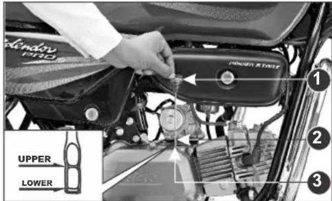
(1) Oil level dipstick (2) Upper level mark (3) Lower level mark
-
Stop the engine & park the motorcycle on its main stand on level ground, remove the oil level dipstick and wipe it clean.
-
Reinsert the oil level dipstick without screwing it in and check the oil level.
-
If required, add the specified oil up to the upper level mark. Do not overfill.
-
Quantity of oil to be filled is 0.75 litre (approx.) during oil changes.
-
Reinstall the oil level dipstick, and check for oil leaks.
ENGINE OIL REPLACEMENT PROCESS
Replace engine oil once in every 6000 kms/6 months whichever is earlier.
Drain engine oil with the engine warm and the motorcycle parked on its main stand.
- To drain the oil, remove the oil level dipstick and drain plug (1).
- After the oil has completely drained, reinstall the drain plug with a new sealing washer (2).
- Fill the crankcase through the filler hole with approximately 0.75 litre of the recommended grade oil.
- Reinstall the oil level dipstick
- Start the engine and allow it to idle for few minutes.
-
Stop the engine and let the engine oil settle down.
Recheck the oil level.7. -
Make sure that oil level is at the upper level mark of the oil level dipstick with the motorcycle parked on its main stand on level ground, and that there are no oil leaks.
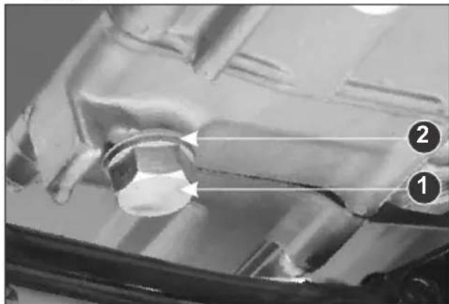
(1) Drain plug
(2) Sealing washer
CAUTION
- Running the engine with insufficient oil can cause serious engine damage.
- Running the engine with excessive oil can cause spark plug fouling & loss in performance.
- Engine oil is a major factor affecting the performance and service life of the engine. Non-detergent, vegetable, or castor based racing oils are not recommended.
TYRES
The tyres that are fitted on your motorcycle are designed to match the performance capabilities of your motorcycle and provide the best combination of handling, braking, durability and comfort. To safely operate your motorcycle, the tyres must be of recommended type and size, in good condition with adequate tread, and correctly inflated.
The recommended tyres size is :
| Front | 2.75 x 18 - 42P/4PR |
| Rear | 2.75 x 18 - 48P/6PR |
Air Pressure
Properly inflated tyres provide the best combination of handling, tread life, and riding comfort. Generally, under inflated tyres wear unevenly, adversely affect handling, and are more likely to fail from being overheated. Under inflated tyres can also cause wheel damage in rocky terrain. Over inflated tyres make your motorcycle ride more harshly, are more prone to damage from surface hazards, and wear unevenly.
natural_image
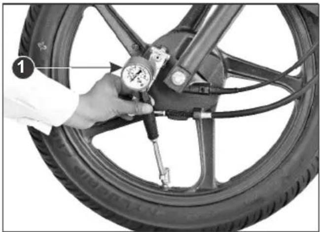
Close-up of a hand using a pressure gauge to measure the wheel rim, with no visible text or symbols.(1) Air Pressure Gauge
Make sure the valve stem caps are secure. If necessary, install a new cap.
The recommended "Cold" tyre pressures are :
| Rider only | Rider and Pillion | |
| Front | 1.75 kgf/cm2(25 psi) | 1.75 kgf/cm2(25 psi) |
| Rear | 2.00 kgf/cm2(28 psi) | 2.50 kgf/cm2(36 psi) |
CAUTION
Over inflation / under inflation will affect the performance.
Inspection
Whenever you check the tyre pressure, you should also examine tyre treads & side walls for wear, damage & foreign objects.
Look for:
- Bumps or bulges in the side of the tyre or the tread. Replace the tyre if you find any bumps or bulges.
- Cuts, splits or cracks in the tyre. Replace the tyre if you can see fabric or cord.
• Excessive tread wear.
Also, if you hit a pothole or hard object, pull to the side of the road as soon as you safely can and carefully inspect the tyres for damage.
Tread Wear
Replace tyres immediately when the wear indicator (1) appears on the tyre. The tread limits are :
Minimum tread depth
Front: 1.0 mm
Rear: 1.0 mm
Check the tread wear indicator for tyre wear.
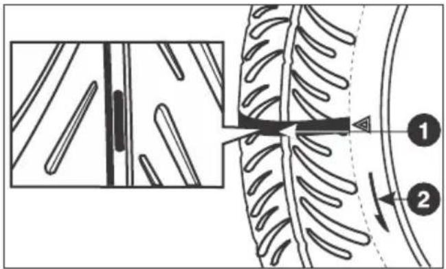
Unidirectional Tyres
Ensure the arrow mark (2) on the tyre is in the same direction as that of forward rotation of the wheel, whenever the tyre is removed and put back in case of puncture.
WARNING
- Using tyres that are excessively worn or improperly inflated can cause a crash in which you can be seriously hurt and killed.
- Operation with excessively worn tyres is hazardous and will adversely affect traction and handling.
- Follow all instructions in this owner's manual regarding tyre inflation and maintenance.
- Under-inflation may result in the tyre slipping on, or tyre coming off the rim.
PRE - RIDE INSPECTION
You should conduct pre-ride inspection before riding the motorcycle to enhance riding comfort and safety.
Clean your motorcycle regularly. It protects the surface finish. Avoid cleaning with products that are not specifically designed for motorcycle surfaces.
Inspect your motorcycle every day before you start the engine. The items listed here will only take a few minutes, and in the long run they can save time, expense, and possibly your life. Please follow the tips as given below:
- Engine oil level - check and top up engine oil if required (page 17). Check for leaks.
- Fuel level - ensure sufficient fuel is available in your fuel tank for your journey (page 16). Check for leaks.
- Front and rear brakes - check operation. Adjust free play if necessary (page 40 & 41).
-
Tyres - check condition and pressure (page 19 & 20).
-
Clutch - check for smooth operation. Adjust free play (page 36 & 37).
- Drive Chain - check condition and slackness (page 38 to 40). Adjust and lubricate if necessary.
- Throttle - check for smooth opening and closing in all steering positions (page 34).
- Lamps and Horn - check that headlamp, tail/stop lamp, turn signal lamps and horn function properly.
- Rear View Mirror - ensure that the rear view mirror gives a good rear view when you are sitting on the motorcycle.
- Fitting & Fasteners - check & tighten if necessary.
- Steering - check for smooth action for easy maneuverability.
- Air Suction Valve - make sure that all tube connections are secured properly.
- Side Stand Indicator - make sure that the side stand is up. If it is in down position the side stand indicator (page 14) will glow on the speedometer panel.
STARTING THE ENGINE
natural_image
Close-up of a black circular dial with 'PUSH LOCK IGNIT' and a diagonal bar, no readable text or symbols beyond the dial pattern.-
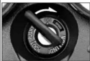
Turn the ignition switch "ON".
-
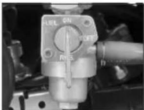
Turn the fuel valve "ON".
natural_image
Close-up of a mechanical valve component with no visible text or symbols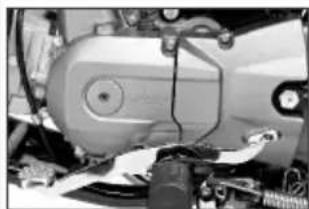
natural_image
Close-up of a mechanical device with visible components and wiring (no text or symbols)- Select neutral position & check ^® indicator glows on instrument cluster with ignition “ON”.
natural_image
Close-up of a mechanical component with a circular dial and lever mechanism (no visible text or symbols)
-
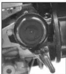
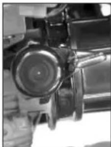
Pull the choke lever upwards to "ON" position as indicated (Use choke during cold conditions).
-
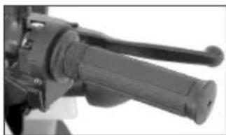
Open the throttle slightly & press the starter switch. (Alternatively kick pedal can be used for starting).
natural_image
Close-up of a mechanical component with a circular lens and lever mechanism (no visible text or symbols)
natural_image
Close-up of a mechanical lever handle and grip (no visible text or symbols)- Push the choke lever downwards to "OFF" position as indicated, after warming up the engine for few seconds.
NOTE :
- To start the engine in any gear position using the electric starter, press the clutch lever and push the starter switch.
- Kick starting will not be possible when the transmission gears are engaged. Shift the transmission into neutral before kick starting.
- Never attempt to kick start while motorcycle is moving forward or backward. This may lead to damage to the product and is not safe as well.
WARNING
Never run the engine in a closed area, the exhaust contains poisonous gases.
Flooded Engine
If the engine fails to start after repeated attempts, it may be flooded with excess fuel. To clear a flooded engine, turn the ignition switch "OFF" and turn the choke lever to "OFF". Close the throttle fully and crank the engine several times with the kick starter. Turn the ignition switch "ON" and start the engine without using choke.
Running In
During first 1000 kms, do not operate the motorcycle at more than 60 kms/hr speed in top gear, 45 kms/hr in third gear, 30 kms/hr in second gear and 15 kms/hr in first gear. Avoid full throttle operation.
During initial running in, newly machined surfaces will be in contact with each other and these surfaces will wear in quickly. Running in precautions till 1000 kms will reduce initial wear of engine components and increase its service life.
RIDING
- After the engine has been warmed up, the motorcycle is ready for riding.
-
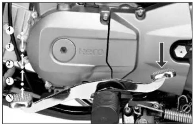
While the engine is idling, press the clutch lever and depress the gearshift pedal to shift into 1^st (low) gear.
-
Slowly release the clutch lever and at the same time, gradually increase engine speed by opening the throttle. Coordination of the throttle and clutch lever will assure a smooth positive start.
- When the motorcycle attains a moderate speed, close the throttle, press the clutch lever and shift to 2^nd gear by depressing the gearshift pedal.
- This sequence is repeated progressively to shift to 3^rd and 4^th (top gear).
Recommended Shifting Speed
1^st 0-20 km/hr
2^nd 15-30 km/hr
3^rd 20-40 km/hr
4^th 30 km/hr and above
CAUTION
Do not shift gears without operating clutch and without closing the throttle otherwise this would lead to damage of gears.
BRAKING
- For normal braking, close the throttle and gradually apply both front and rear brakes simultaneously while shifting down gears to suit your road speed.
- For maximum deceleration/quick stopping, close the throttle and apply the front and rear brakes simultaneously.
WARNING
- Independent use of only the front or rear brake increases stopping distance.
- Extreme braking may cause wheel locking and reduce control over the motorcycle.
- Wherever possible, reduce speed or apply brake before entering turn, closing the throttle or braking in mid turn may cause wheel slip. Wheel slip will reduce control over the motorcycle.
-
When riding in wet or rainy conditions, or on loose surfaces the ability to stop the motorcycle reduces.
-
All your actions should be smooth under these conditions. sudden accelerations, braking or turning may cause loss of control. For your safety, exercise extreme caution when braking, accelerating or turning.
- When descending a long steep slope use engine braking (power) by changing to lower gears, with intermittent use of both brakes. Continuous brake application can overheat the brakes and reduce their effectiveness.
PARKING
After stopping the motorcycle, shift the transmission to neutral, turn the fuel valve "OFF", turn the ignition switch "OFF", park the motorcycle on main stand, lock the steering and remove the key
CAUTION
- Park the motorcycle on firm level ground to prevent overturning.
- While parking vehicle on side stand engage the first gear.
ANTI-THEFT TIPS
-
Always lock the steering and never leave the key in the ignition switch.
-
Park your motorcycle in a locked garage whenever possible.
-
Use an additional anti-theft device of good quality.
-
Put your name, address and phone number in this Owner's Manual and keep it in your motorcycle at all times.
Many times stolen motorcycles are identified by information in the Owner's Manuals that are still with them.
NAME :
ADDRESS :
PHONE NO :
UTILITY BOX
To store some important utility items a utility box has been provided.
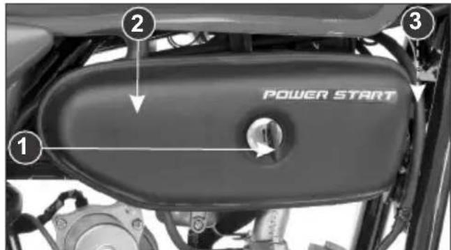
(1) Key
(2) Cover
(3) Hook
To open, insert the key (1), rotate it clockwise, pull the cover (2), and slide it sideways to disengaged it from the hook (3).
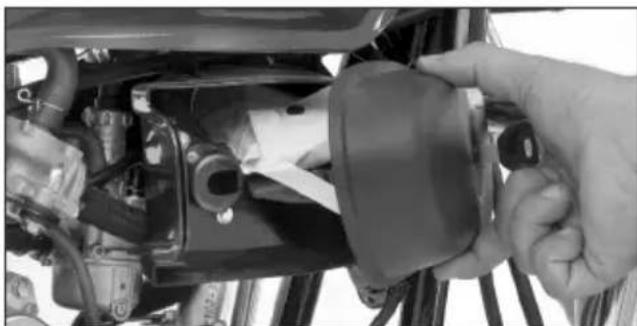
natural_image
Close-up of a hand adjusting a car seatbelt component (no visible text or symbols)To close, engage the hook and press gently. Hold the key in clockwise direction, slide the cover back and release the key.
TOOL KIT
The tool kit (1) is stored in the utility box. Some emergency repairs, minor adjustments and parts replacement can be performed with the tools contained in the kit.
Kit consists of following tool:
- Tool bag - 1 No.
• +,- No. 2 Driver - 1 No. - Grip - 1 No.
- Box wrench 16 x 14 - 1 No.
- Pin spanner- 1 No.
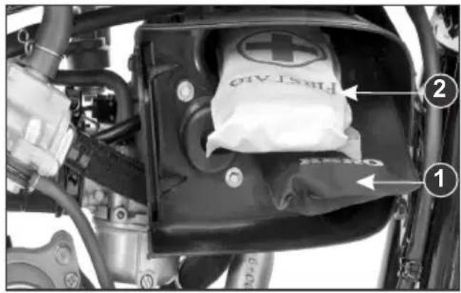
(1) Tool kit
(2) First aid kit
FIRST AID KIT
The first aid kit (2) is stored in the utility box. Some emergency first aid can be performed by medicine contained in the kit.
Kit contains the following items :
1) Anticeptic Cream - 1 No.
2) Sterilised Dressing - 1 No.
3) Water Proof Plaster - 1 No.
4) Elastic Bandage - 1 No.
5) Gauze (Rolled Bandage) - 1 No.
6) Sterilised Elastic Plaster - 1 No.
7) First Aid Bag - 1 No.
SAFETY PRECAUTIONS
- Make sure the engine is "OFF" before you begin any maintenance or repairs. This will help to eliminate several potential hazards :
* Carbon monoxide poisoning from engine exhaust.
Be sure there is adequate ventilation whenever you operate the engine.
* Burns from hot parts.
Let the engine and exhaust system cool before touching.
* Injury from moving parts.
Do not run the engine unless instructed to do so.
- Read the instruction before you begin, and make sure you have the tools and skills required.
- To help prevent the motorcycle from falling over, park it on a firm, level surface on the mainstand.
- To reduce the possibility of a fire or explosion, be careful when working around petrol or batteries. Use only nonflammable solvent, not petrol, to clean parts. Keep cigarettes, sparks and flames away from the battery and all fuel-related parts.
Remember that your Authorised Hero MotoCorp Dealer knows your motorcycle best and is fully equipped to maintain and repair it.
To ensure best quality and reliability, it is recommended to use Hero MotoCorp genuine parts for repair and replacement.
MAINTENANCE
MAINTENANCE SCHEDULE
Dear Customer,
We would strongly recommend the following schedule, to keep your motorcycle in perfect running condition and healthy environment. Motorcycle subjected to severe use or ridden in dusty area will require more frequent servicing.
| ITEMS | WHICHEVER COMES FIRST | DURING FREE SERVICE PERIOD | AFTER FREE SERVICE ONCE IN EVERY | |||||||||
| SERVICE | 1st | 2nd | 3rd | 4th | 5th | 6th | ||||||
| DAYS | 1st 60 N | Next 100 | Next 100 | Next 100 N | Next 100 Next 100 | |||||||
| KMS. | 500-750 | 3000-3500 | 5000-6500 | 9000-9500 | 12000-12500 | 15000-15500 | 3000 6000 9000 12000 15000 | |||||
| Fuel Line | I | I | I | I | I | I | I | |||||
| Throttle Operation | I,A | I,A | I,A | I,A | I,A | I,A | I,A | |||||
| Carburetor | C,A | A | C,A | A | C,A | A | A | C,A | ||||
| Air Cleaner* | C | C | C | C | R | C | C | R | ||||
| Spark Plug | I,C,A | I,C,A | I,C,A | I,C,A | R | I,C,A | I,C,A | R | ||||
| Valve Clearance | I,A | I,A | I,A | I,A | I,A | I,A | I,A | |||||
| Engine Oil** | O | I,T | O | I,T | O | I,T | I,T | O | ||||
| Engine Oil Strainer Screen | C | C | C | C | ||||||||
| Engine Oil Centrifugal Filter | C | C | C | C | ||||||||
| Electric Starter | I | I | I | I | I | I | I | |||||
| Electric Starter Chain | L | L | L | L | ||||||||
| Oil Circulation | I | I | I | I | I | I | I | |||||
| Drive Chain | I,C,L,A at every 2000 kms I,C,L,A at every 2000 kms@ | |||||||||||
| Battery Voltage | I | I | I | I | I | I | I | |||||
| Brake Shoe | I,A | I,A | I,A | I,A | I,A | I,A | I,A | |||||
| Brake System (Brake Cam & Brake Pedal) | - | C,L | - | C,L | - | C,L | - | C,L | ||||
| Stop Lamp Switch | I,A | I,A | I,A | I,A | I,A | I,A | I,A | |||||
| Headlamp Focus | I,A | I,A | I,A | I,A | I,A | I,A | I,A | |||||
| Clutch | I,A | I,A | I,A | I,A | I,A | I,A | I,A | |||||
| Side Stand/Main Stand | L | L | L | L | L | L | L | |||||
| Side Stand Switch | I,C | I,C | I,C | I,C | I,C | I,C | I,C | |||||
| Fasteners*** | I | I | I | I | I | I | I | |||||
| Wheels/Tyres | I | I | I | I | I | I | I | |||||
| Steering Head Bearing | I | I,A | I | I,A | I,L,A | I | I | I,A | I,L,A | |||
| Front Suspension/Oil**** | I | I | I | I | I | I | I | - | ||||
| Secondary Air Injection | - | - | I | - | I | - | - | I | ||||
| Muffler (Catalytic Converter) | - | - | I,E I,E I,E | - | - | - | ||||||
* More frequent cleaning may be required when riding in dusty areas.
** Replace engine oil once in every 6000 kms. Top up once in every 3000 kms.
*** Inspect & maintain specified torque.
****Replace once in every two years or 30000 kms. whichever is earlier.
- Check idle CO emission along with idle r/min CO adjustment (if required).
@ Visit Authorised Hero MotoCorp workshop for inspection, cleaning, lubrication and adjustment of drive chain at every 2000 kms.
NOTE:- Always wipe the water from the motorcycle after washing. Use clean soft cloth or pressurised air for completely drying the water.
I: INSPECT R: REPLACE C: CLEAN L: LUBRICATE A: ADJUST IF REQUIRED O: OIL CHANGE T: TOP UP E: EMISSION CHECK
OIL FILTER SCREEN & CENTRIFUGAL FILTER
- Drain the engine oil thoroughly.
- Remove the kick starter pedal (1), disconnect the clutch cable (2), remove the muffler (3), remove the rider footrest (4) and remove the right crankcase cover (5).
- Remove the oil filter screen (6) and wash it in clean non flammable high flash point solvent (kerosene).
- Reinstall the filter screen with the sharp edged side facing inwards.
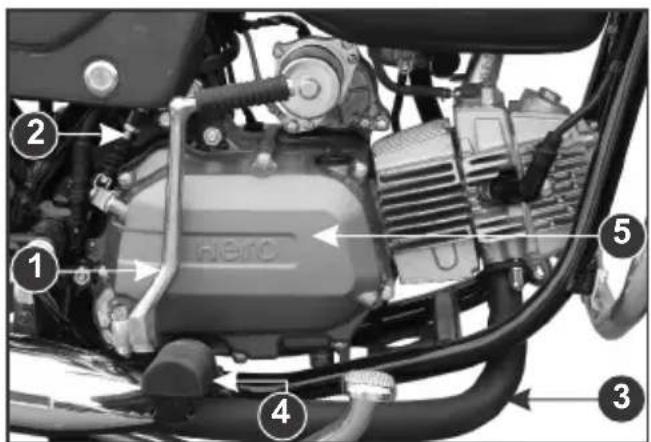
(1) Kick Starter Pedal (2)
Clutch Cable
(3) Muffler (4) Rider foot rest
(5) Right crankcase cover
- Remove centrifugal filter cover (7) & clean centrifugal filter (8) with non flammable high flash point solvent (kerosene).
- Reinstall the centrifugal filter cover, right crankcase cover, kick starter pedal, rider foot rest and muffler.
- Fill the crankcase with clean engine oil as per specification.
NOTE
Clean filters as specified in the maintenance schedule.
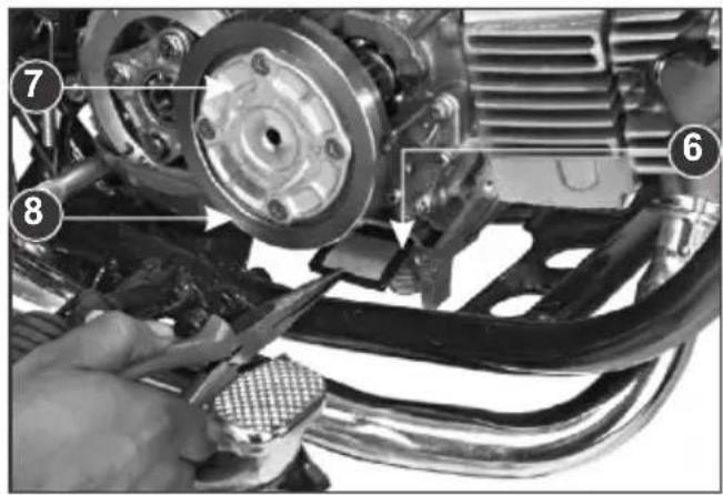
(6) Oil filter screen
(7) Centrifugal filter cover
(8) Centrifugal filter
SPARK PLUG
natural_image
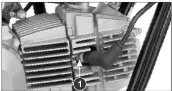
Close-up of a mechanical component with a hand adjusting a grille and cable, labeled with number 1 (no readable text or symbols)(1) Spark Plug
Recommended spark plugs : NGK-CR7HSA, BOSCH-UR4AC, Champion-P-RZ9HC (Federal Mogul)
For most riding conditions this spark plug heat range number is satisfactory. However, if the motorcycle is going to be operated for extended periods at high speeds or near maximum power in hot climates, the spark plug should be changed to a cold heat range number; consult Authorised Hero MotoCorp workshop on this if required.
- Clean any dirt around the spark plug base.
- Disconnect the spark plug cap and remove the spark plug with the help of spark plug wrench provided in the tool bag.
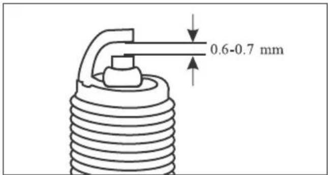
- Visually inspect the spark plug electrodes for wear. The centre electrode should have square edges and the side electrode should not be eroded. Discard the spark plug if there is apparent wear or if the insulator is cracked or chipped.
- Make sure that the spark plug gap is 0.6-0.7 mm using a wire-type feeler gauge. If adjustment is necessary, bend the side electrode carefully. Make sure the plug washer is in good condition.
- With the plug washer attached, thread the spark plug in by hand to prevent cross-threading.
- Tighten a new spark-plug 1/2 turn with a spark plug wrench to compress the washer. If you are reusing a plug, it should only take 1/8-1/4 turn after the plug seats.
AIR CLEANER
The air cleaner element is of Dry Paper Pleated type it should be serviced at regular intervals (page 28). When riding in dusty areas, more frequent service may be necessary.
- Insert the ignition key into the side cover lock (1). Remove the side cover (2) by turning the key clockwise. Pull out lug (3) from the grommet and slide the cover as per direction indicator (4).
- Remove the air cleaner cover screws (5) and the cover (6).
- Press the mounting clamp (8) to release the air cleaner assembly from the housing and remove the air cleaner assembly (7).
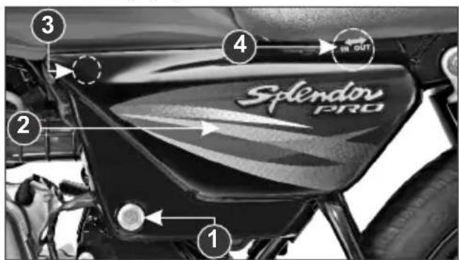
(1) Side cover lock
(2) Side cover
(3) Lug
(4) Direction indicator
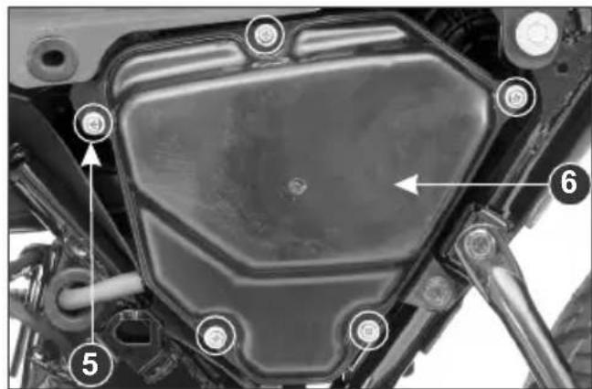
(5) Air cleaner cover screws
(6) Air cleaner cover
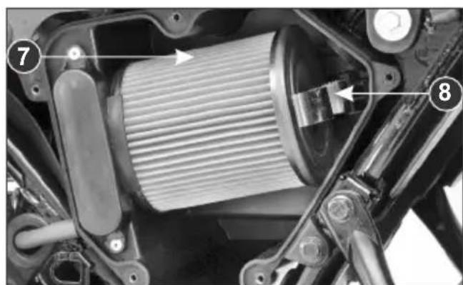
(7) Air cleaner assembly
(8) Mounting clamp
- Air Cleaner Cleaning
- Remove the Air Cleaner Element (9) from the Element Holder (10).
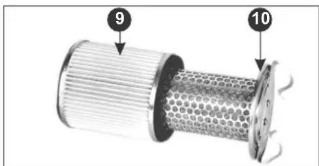
(9) Air cleaner element (10) Element holder
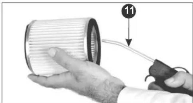
- The Air Cleaner Element should be cleaned by blowing moisture free pressurized air.
- Start cleaning by directing the air nozzle (11) inside the element and cleaning it by rotating the element about its axis.
natural_image
Close-up of hands holding a cylindrical mechanical component with a cable, no visible text or symbols(11) Air nozzle
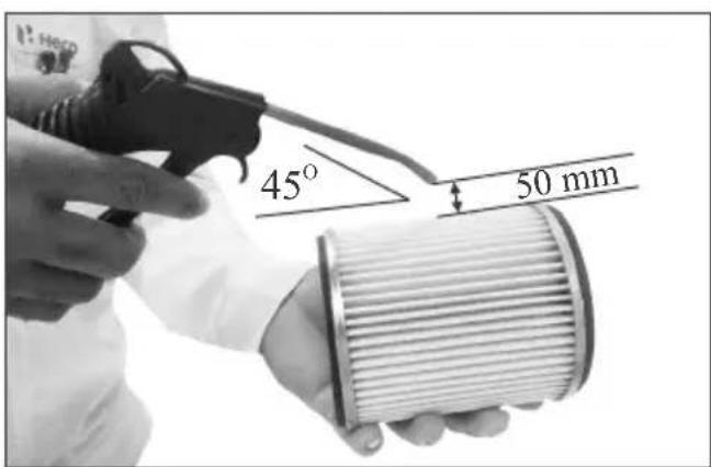
- Now blow the dust from the surface of the paper element about 50 mm away from it, with the air nozzle (11) at an angle of 45 and moving it along the paper pleats.
- Replace it earlier if it becomes very dirty, damaged on surface or on the sealing area. Install the air cleaner element on holder, insert the air cleaner assembly into the inlet air duct & press gently to fix the mounting clamp in housing. Ensure cover lug should take proper seat on the other side of the mounting clamp.
CAUTION
- Never wash the air cleaner element. Only blow air for cleaning the dust, as explained. Replace air cleaner element every 12000 kms.
- Never blow air initially from outside to inside as the fine dust particles may go deep inside the element.
THROTTLE OPERATION Cable Inspection
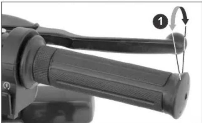
Check for smooth rotation of the throttle grip from the fully open to the fully closed position. Check at full left and full right steering positions. Inspect the condition of the throttle cable from the throttle grip down to the carburetor. If the cable is kinked, chafed or improperly routed, it should be replaced or rerouted. Standard throttle grip free play (1) is approximately 2-6 mm of grip rotation.
natural_image
Close-up of a mechanical device with a lever and adjustment knob, no visible text or symbols(1) Free play 2-6 mm
Free Play Adjustment
Slide the grommet (2), loosen the lock nut (3) and turn the adjuster (4).
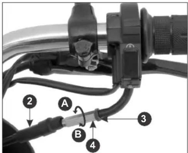
(2) Grommet
(3) Lock nut
(4) Adjuster
(A) Decrease free play
(B) Increase free play
VALVE CLEARANCE
Excessive valve clearance will cause noise, and little or no clearance will prevent the valve from closing and cause valve damage and power loss. Check valve clearance at the specified intervals (page 28).
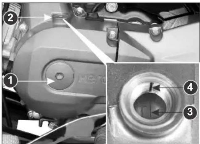
(1) Crankshaft hole cap (2) Timing hole cap (3) 'T' mark (4) Index mark
NOTE
The checking or adjustment of valve clearance should be performed while the engine is cold. The clearance will change as the engine temperature rises.
-
Remove the crankshaft hole cap (1), timing hole cap (2) and tappet covers.
-
Rotate the flywheel anticlockwise until the 'T' mark (3) on the flywheel coincides with the index mark (4) on the left crankcase cover. In this position the piston will either be on the compression or exhaust stroke.
The adjustment must be made when the piston is at Top Dead Center and both the inlet and exhaust valves are closed.
This condition can be determined by moving the rocker arms. If they are free, it is an indication that the valves are closed and the piston is in compression stroke. If they are tight, the valves are open, rotate the flywheel 360 °anticlockwise and re-align the 'T' mark with the index mark.
- Check the clearance by inserting the feeler gauge (5) between the adjusting screw (6) and valve stem.
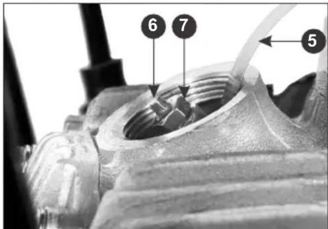
(5) Feeler gauge (6) Adjusting screw (7) Lock nut
Standard clearance
In. 0.10 mm Ex. 0.10 mm Adjust by loosening the lock nut (7) and turning the adjusting screw until there is
a slight drag on the feeler gauge. After tightening the lock nut, check again the clearance.
- Install all parts in the reverse order of disassembly.
NOTE
Before inserting the feeler gauge, smear a bit of engine oil to avoid damage to the feeler gauge.
CARBURETOR
Idle speed
The carburetor is factory pre-set in order to achieve optimum performance and meet emission standards.
However in case of specific requirement of tuning due to engine stalling in idle speed, please follow the instructions given hereunder:
-
Warm up the engine and park the motorcycle on the main stand.
-
Adjust idle speed with the throttle stop screw (1).
IDLE SPEED: 1400 ± 100 r/min
CAUTION
Never adjust air screw (2). Air screw adjustment is to be done only by Authorised
Hero MotoCorp workshop.
If air screw is tampered it affects the overall performance characteristics of the vehicle.

(1) Throttle stop screw (A) Decrease r/min
(2) Air screw (B) Increase r/min
(3) Throttle position sensor switch
Throttle Controlled Ignition System (TCIS) Throttle position sensor switch (3) alters the ignition timing as per the throttle operation and ensures optimum driving performance.
CLUTCH
Clutch adjustment may be required if the motorcycle stalls when shifting into gear or tends to creep or if the clutch slips, causing acceleration to lag behind engine speed. Normal clutch lever free play (1) is 10-20 mm at the lever (2).
- To adjust the free play, loosen the lock nut (3). Turn the adjusting nut (4) to obtain the specified free play. Tighten the lock nut and check the adjustment.
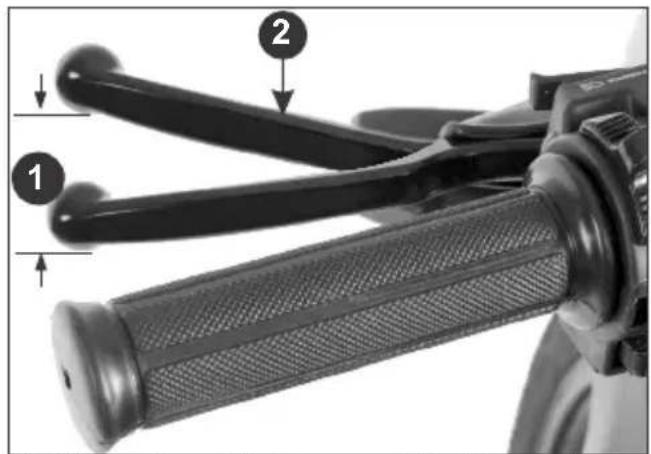
(1) Free play 10-20 mm (2) Clutch lever
- Start the engine, press the clutch lever and shift into gear. Make sure the engine does not stall and the motorcycle does not creep. Gradually release the clutch lever and open the throttle. The motorcycle should start smoothly and accelerate.
NOTE
Check that the clutch cable routing is correct.
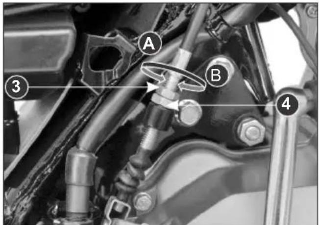
(3) Lock nut
(A) Decrease free play
(4) Clutch cable adjusting nut
(B) Increase free play
NOTE
If proper adjustment cannot be obtained or the clutch does not work correctly, visit your Authorized Hero MotoCorp workshop.
Other Checks
- Check the clutch cable for kinks or signs of wear that could cause sticking or failure.
- Check for clutch cable model. Use genuine clutch cables.
- Check for clutch cable routing.
DRIVE CHAIN
The service life of the drive chain is dependent upon proper lubrication and adjustment. Poor maintenance can cause premature wear or damage to the drive chain and sprockets. The drive chain (1) should be checked and lubricated as part of the Pre-ride Inspection (page 21). Under severe usage, or when the motorcycle is ridden in unusually dusty areas, more frequent maintenance will be necessary.
Inspection
- Turn the engine "OFF", park the motorcycle on its main stand and shift the transmission to neutral. Remove hole cap (2).
- Drive chain slack (3) should be adjusted to allow approximately 25 mm vertical movement by hand.
Rotate the wheel and check drive chain slack as the wheel rotates. Drive chain slack should remain constant as the wheel rotates. If the chain is slack in one section and tight in another, some links are kinked and binding. Binding can be eliminated by frequent lubrication.
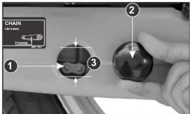
(1) Drive chain
(2) Hole cap
(3) Drive chain slack 25 mm
- Turn the chain to view chain lock plate (4) inside the hole. Ensure that the chain lock plate open end (5) is installed in the opposite direction of the chain rotation.
- Inspect the sprocket teeth for wear or damage.
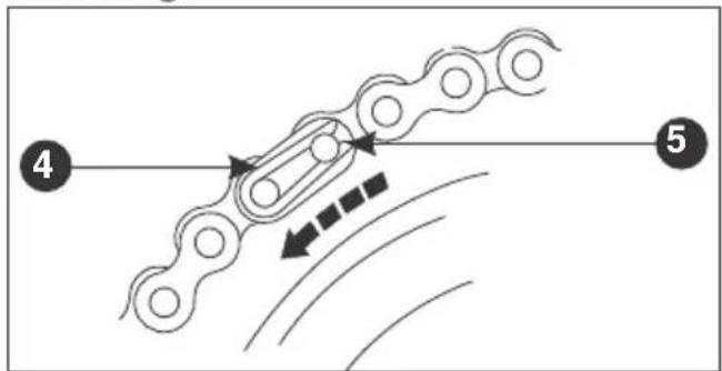
(4) Chain lock plate
(5) Open end
- If the drive chain or sprockets are excessively worn or damaged, they should be replaced. Never use a new chain with worn out sprockets since this will result in rapid chain wear.
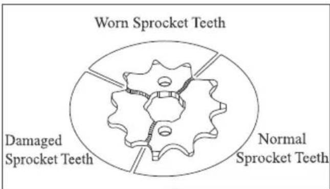
Adjustment
- Park the motorcycle on its main stand with the transmission in neutral and the ignition switch in "OFF" position.
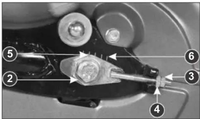
- Loosen the rear axle nut (1) and sleeve nut (2).
- Loosen the drive chain lock nut (3).
- Turn both the adjusting nuts (4) in an equal number of turns until the correct
drive chain slack is obtained. Turn the adjusting nut clockwise to decrease the slack or anticlockwise to increase the slack of the chain.
- Align the chain adjuster index mark (5) with the corresponding scale graduations (6) on both the sides of the swing arm equally.
- If the drive chain slack is excessive when the rear axle is moved to the farthest limit of adjustment, the drive chain is worn and must be replaced.
• Tighten the rear axle nut and sleeve nut. - Align the chain adjuster index mark (5) with the corresponding scale graduations (6) on both the sides of the swing arm equally.
- If the drive chain slack is excessive when the rear axle is moved to the farthest limit of adjustment, the drive chain is worn and must be replaced.
- Tighten the rear axle nut and sleeve nut.
- Rear axle nut torque: 5.4 kgf-m.
- Sleeve nut torque: 4.4 kgf-m.
- Check the drive chain slack again.
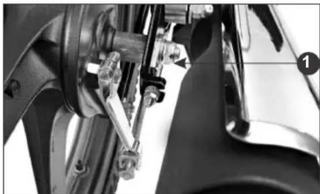
natural_image
Close-up of mechanical components including a brake caliper and suspension bracket (no visible text or symbols)(1) Rear axle nut
(2) Sleeve nut
(3) Drive chain lock nut
(4) Drive chain adjusting nut
(5) Index mark (6) Scale graduation
- Rear brake pedal free play and stop lamp switch free play are affected when repositioning the rear wheel to adjust driv chain slack. Check rear brake pedal free p and adjust as necessary (page 41 & 42).
Lubrication
- Turn the engine "OFF", park the motorcycle on its main stand and shift the transmission into neutral.
- Lubricate the drive chain by applying liberal amount of SAE # 90 oil.
CAUTION
Regular adjustment and lubrication as per the maintenance schedule would ensure high performance and longer life.
NOTE
Visit authorised Hero MotoCorp workshop for inspection, cleaning, lubrication and adjustment of drive chain at every 2000 kms.
FRONT BRAKE
Adjustment
- Park the motorcycle on its main stand.
- Measure the distance, the front brake lever (1) moves before the brake starts to take hold. Free play (2) should be 10-20 mm at the tip of the brake lever.
- If adjustment is necessary, turn the adjusting nut (3).
Make sure that cut-out on the adjusting nut is seated on the brake joint pin (4) after making final free play adjustment.
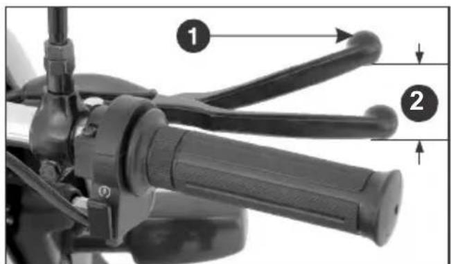
(1) Front brake lever (2) Free play 10-20 mm
- Apply the brake several times and check for free wheel rotation when released.
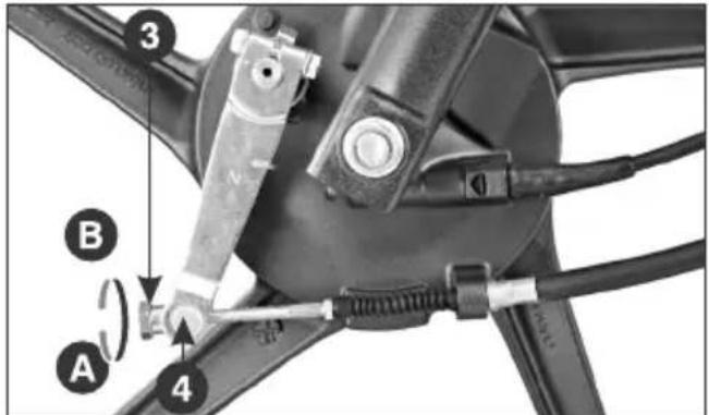
(3) Adjusting nut (4) Brake joint pin
(A) Decrease freeplay (Clockwise)
(B) Increase freeplay (Anti-Clockwise)
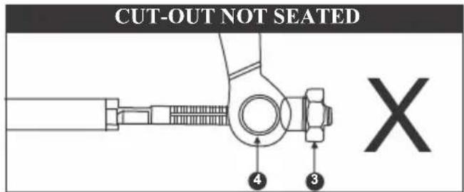
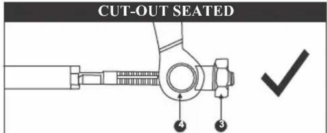
(3) Adjusting nut
(4) Brake joint pin
NOTE
If proper adjustment cannot be obtained by this method, visit your Authorized Hero MotoCorp workshop.
REAR BRAKE
Adjustment
- Park the motorcycle on its main stand.
- Measure the distance of brake pedal (1) moves before the brake starts to take hold. Free play (2) should be 20-30 mm.
- If adjustment is necessary, turn the rear brake adjusting nut (3).
Make sure that the cut-out on the adjusting nut is seated on the brake joint pin (4) after the final adjustment has been made.
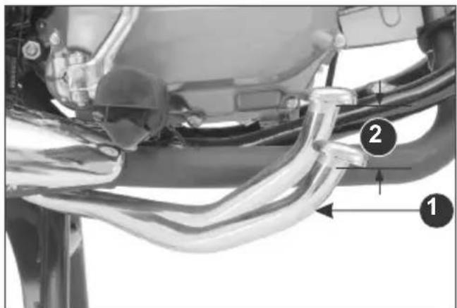
(1) Rear brake pedal (2) Free play 20-30 mm
- Apply the brake several times and check for free wheel rotation when released.
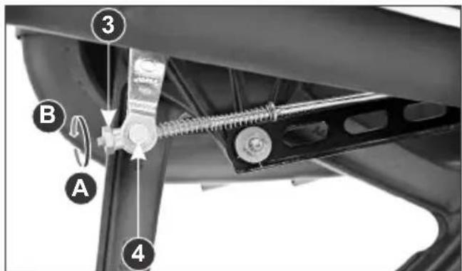
(3) Adjusting nut (4) Brake joint pin
(A) Decrease free play (Clockwise)
(B) Increase free play (Anti-Clockwise)
NOTE
If proper adjustment cannot be obtained by this method, visit your Authorised Hero MotoCorp workshop.
BRAKE WEAR INDICATORS
When the brake is applied, an arrow (1), fixed to the brake arm (2), moves toward a reference mark (3) on the brake panel (4). If the arrow aligns with the reference mark on full application of the brake, the brake shoes must be replaced.
Front Brake Wear Indication
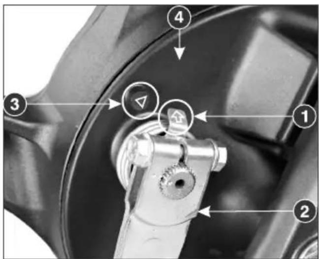
(1) Arrow
(2) Brake arm
(3) Reference mark
(4) Brake panel
Rear Brake Wear Indication
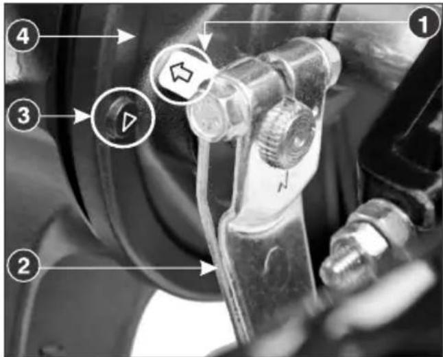
(1) Arrow
(3) Reference mark
(2) Brake arm
(4) Brake panel
BATTERY
Location
The battery (1) is located behind the right side cover.
Specification
*MF Battery, MF-4:12V 3 Ah
*MF stands for Maintenance Free
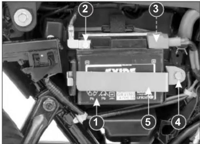
(1) Battery (2) (-)ve terminal (3) (+)ve terminal (4) Bolt (5) Battery clamp
It is not necessary to check the battery electrolyte level or add distilled water as the battery is a Maintenance-Free (sealed) type. If your battery seems weak and/or electrolyte is leaking (causing hard starting or other electrical troubles), contact your Authorised Hero MotoCorp workshop.
NOTE :
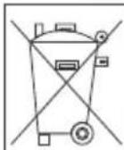
This symbol on the battery means that this product must not be treated as household waste.
| This symbol on the battery means the old battery must be returned to your Authorised Hero MotoCorp workshop as it must be treated as recyclable material. |
- Battery is a Maintenance - Free (sealed) type and can be permanently damaged if the sealing strip is removed.
- An improperly disposed battery can be harmful to the environment and human health. Always confirm local regulations for battery disposal.
WARNING
- The battery gives off explosive hydrogen gas during normal operation.
- A spark or flame can cause the battery to explode with enough force to seriously hurt you.
- Wear protective clothing and a face shield, or have skilled technician do the battery maintenance.
Battery charging
Always visit your Authorised Hero MotoCorp workshop if you see any symptom of battery discharge as earliest as
possible to get the battery charged. The battery has a tendency to discharge rapidly if optional electrical accessories are fitted on the motorcycle.
Battery storage
- If in case your motorcycle is not used for more then a month remove the battery, fully charge and store in a cool and dry place.
- If the battery is expected to be stored for more then two months, ensure to fully charge the battery once in a month.
- Always ensure the battery is fully charged before installation.
- Ensure the battery leads are properly connected to the battery terminals during installation.
Battery removal
- Make sure the ignition switch is "O FF"
- Insert the ignition key into the right side cover lock. Remove the side cover by turning the key clockwise. Pull out lug from the grommet and slide the cover as per direction indicator (available on the top of right side cover).
-
Disconnect the negative (-) terminal lead from the battery first, then disconnect the positive (+) terminal lead.
-
Remove the battery clamp bolt (page 43).
- Pull out the battery from the battery box.
Battery installation
- Reinstall in the reverse order of removal. Be sure to connect the positive (+) terminal first, then the negative (-) terminal.
- Check all bolts and other fasteners are secure.
FUSE REPLACEMENT
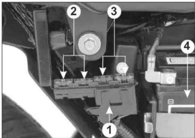
Fuse Box (1) : Location : Mounted on the clamp near battery (4).
Fuse Type : Blade fuse
In circuit fuse (2): 15A, 10A
Spare fuse (3): 15A, 10A
WARNING
- Never use a fuse with a different rating from that specified. It may lead to serious damage to the electrical system or a fire due to short circuit.
- Battery gives off explosive gases. Keep sparks, flames & cigarettes away.
CAUTION
- Do not attempt to start or ride the motorcycle without a charged battery, it can cause fusing of the bulbs and permanent damage to certain electrical components.
- Turn the ignition switch "OFF" before checking or replacing the fuse to prevent accidental short-circuiting.
STOP LAMP SWITCH
The stop lamp switch (1) must be adjusted so that stop lamp will glow when rear brake is applied. Rear brake pedal free play (page 41 & 42) should be adjusted before performing stop lamp switch adjustment. The procedure for adjusting stop lamp switch is as follows:
- Turn the ignition switch to the "ON" position.
- Turn the adjusting nut (2) to position stop lamp switch at a point where the stop lamp will glow just before the brake pedal is depressed to the limit of its free
play. Turn the adjusting nut in direction (A) to advance switch timing or in direction (B) to retard switch timing.
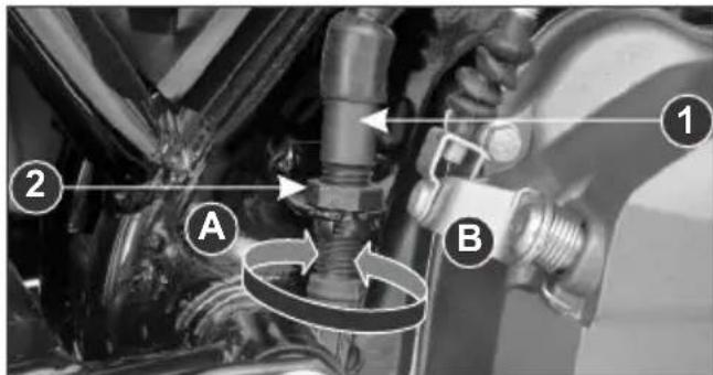
(1) Stop lamp switch
(A) Advance
(2) Adjusting nut
(B) Retard
SIDE STAND
Check the side stand for proper function.
- Check the spring (1) for damage or loss of tension and the side stand assembly for free movement.
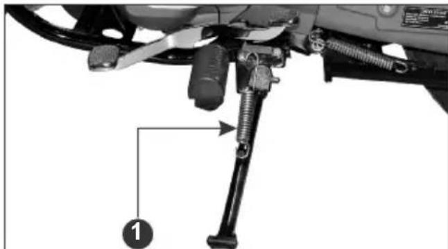
natural_image
Mechanical device with a bipod and lever assembly, labeled with number 1 (no text or symbols on the diagram itself)(1) Side stand spring
-
Check whether the side stand indicator (2) glows when vehicle is parked on side stand.
-
While the vehicle is removed from side stand, the side stand indicator (2) should not glow.
-
If the side stand indicator (2) does not operate as described in steps 2 or 3, please visit your Authorised Hero MotoCorp workshop.
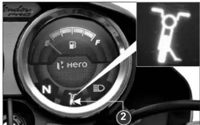
(2) Side stand indicator
CAUTION
Ensure that adequate care should be taken while cleaning the side stand switch.
HEADLAMP ADJUSTMENT
Headlamp is factory pre-set. However in case of adjustment required, please follow the steps as given below :
- Headlamp adjustment is done by the headlamp adjusting screw (1) located below headlamp.
- Park the motorcycle on level ground.
- Adjust the headlamp beam vertically by rotating the screw. Rotate the screw clockwise for downward adjustment and anticlockwise for upward adjustment of headlamp beam.
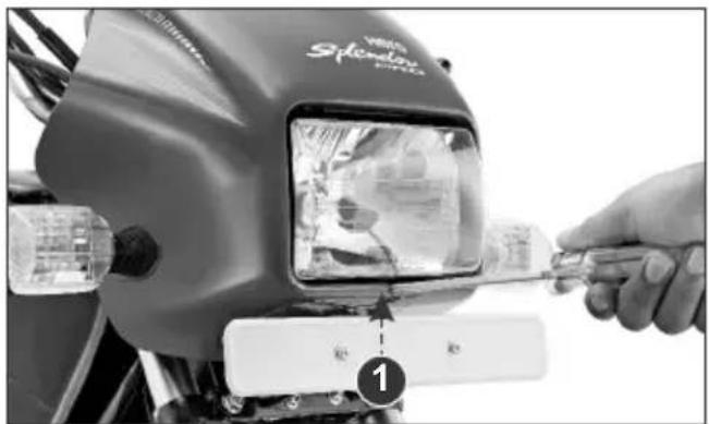
(1) Adjusting screw
WARNING
An improperly adjustedheadlamp may blind oncoming driver or it may fail to light the road for a safe distance.
SUSPENSION
Inspection
- Check the front forks by locking the front brake and pumping the front fork up and down vigorously. The suspension action should be smooth and there should be no oil leakage.
- Check the rear shock absorber by pushing hard downwards on rear carrier while the motorcycle is not parked on stand. The suspension action should be smooth and there should be no oil leakage.
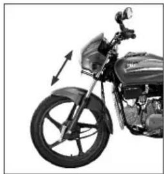
natural_image
Side view of a motorcycle with visible wheel and side-mounted sensor (no text or symbols)Front
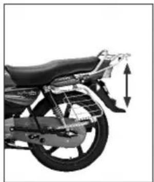
natural_image
Side view of a motorcycle's front wheel and side rear seat, showing structural components (no text or symbols visible)Rear
Rear Shock Absorber Adjustment
Rear shock absorber adjustment can be made according to the load/road conditions.
• In direction A Stiffer
• In direction B Softer
NOTE
Always adjust both the rear shock absorbers to the same position. Use the rear shock absorber adjustment tool (Pin Spanner) (1) available in the tool kit.
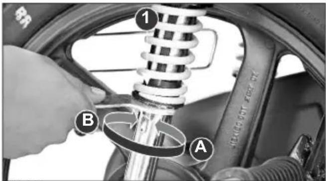
(1) Pin spanner
FRONT WHEEL REMOVAL
- Raise the front wheel off the ground.
- Remove the speedometer cable (1) by pressing tab (2) & pulling cable out.
- Disconnect the brake cable (3) from brake arm (4) and brake panel (5) by removing the front brake adjusting nut (6).
- Remove the axle nut (7).
- Remove the axle and then remove the wheel.
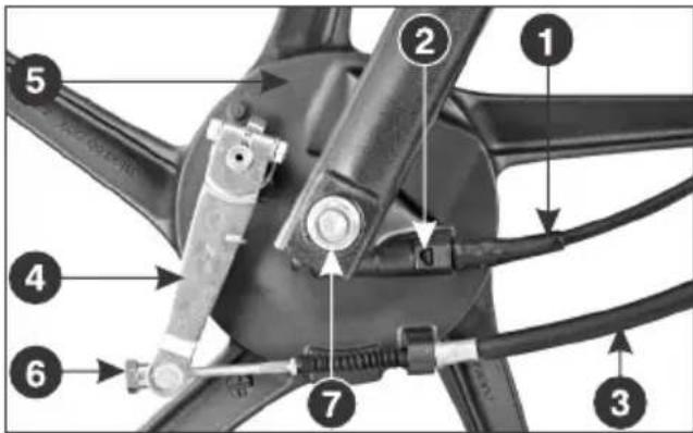
(1) Speedometer cable
(2) Tab
(3) Front brake cable
(4) Brake arm
(5) Brake panel
(6) Front brake adjusting nut
(7) Axle nut
Installation Notes
• Reverse the removal procedure.
- Install the front wheel by ensuring that the lug (8) on the left fork is located in the slot (9) in the brake panel.
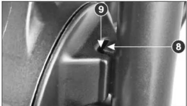
(8) Lug (9) Slot
- Rotate the front wheel & see if the speedometer needle is working.
- Tighten the axle nut. Axle nut torque : 5.4 kgf-m
- Adjust the brake (page 40 & 41).
- After installing wheel, apply the brake several times and check for free wheel rotation when released.
REAR WHEEL REMOVAL
- Raise the rear wheel off the ground.
- Remove the rear brake adjusting nut (1) and disconnect the brake rod (2) from the brake arm (3) by pushing down the brake pedal. Disconnect the brake stopper arm (4) from the brake panel (5) by removing split pin (6) and nut (7).
- Remove the axle nut (8) and pull out the axle (9). Remove the wheel.
Installation Notes
• Reverse the removal procedure
- Axle nut torque : 5.4 kgf-m
Brake stopper arm nut torque : 2.2 kgf-m
- Adjust the brake (page 41 & 42) and drive chain (page 38). to 40
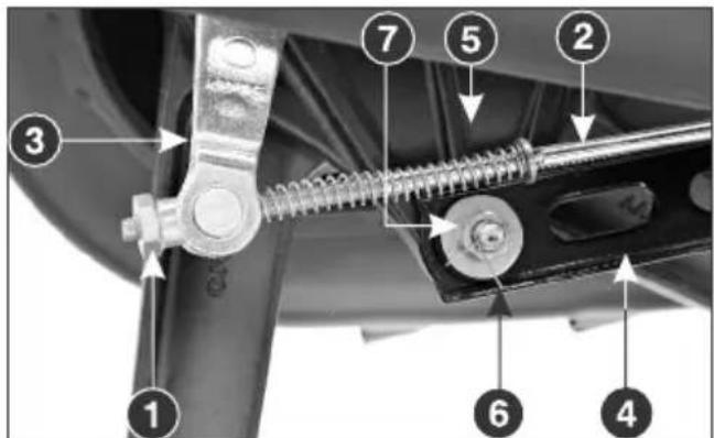
(1) Rear brake adjusting nut (2) Rear brake rod (3) Brake arm (4) Brake stopper arm (5) Brake panel (6) Split pin (7) Lock nut
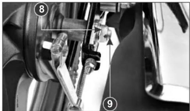
(8) Axle nut
(9) Axle
- After installing the wheel, apply the brake several times and check for free wheel rotation when released.
CAUTION
Always replace used split pins with new ones.
WASHING THE MOTORCYCLE
Follow the below mentioned steps for washing the motorcycle.
- Wet the motorcycle with light water spray. Avoid directing water to muffler outlet and electrical parts.
-
Clean the headlamp lens and other plastic parts using a cloth or sponge dampened with a solution of mild detergent and water. Rub the soiled area gently rinsing it frequently with fresh water.
-
After cleaning spray water thoroughly.
- Dry the motorcycle by wiping with dry soft cloth.
NOTE
- Our authorised dealership take all above mentioned precautions like recommended detergents and usage of muffler caps/ plugs during wash to ensure quality of wash.
- Do not use high pressure water (or air). It can damage certain parts of motorcycle.
CATALYTIC CONVERTER
This motorcycle is equipped with a catalytic converter in the muffler.
The catalytic converter contains noble metals that serve as catalyst, promoting chemical reactions to convert CO and HC in the exhaust to C_2O and H_2O (water vapour).
A defective catalytic converter contributes to air pollution and can impair your engine's performance.
Follow these guidelines to protect your motorcycle's catalytic converter.
• Always use unleaded petrol. Even a small amount of leaded petrol can contaminate the catalyst metals, making the catalytic converter ineffective.
- Keep the engine tuned up.
AIR SUCTION VALVE
natural_image
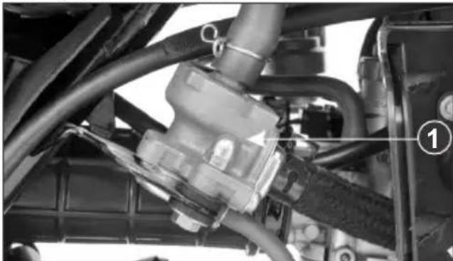
Close-up of mechanical components with hoses and connectors, no visible text or symbols(1) Air Suction Valve
To meet emission standards this motorcycle is provided with the air suction valve. Air Suction Valve (1) supplies fresh air from the air filter to the exhaust manifold to convert carbon monoxide to carbon dioxide. This reduces the CO% in the vehicle's exhaust.
BASIC TROUBLESHOOTING
1. STARTING TROUBLE - ENGINE DOES NOT START
A. Fuel System
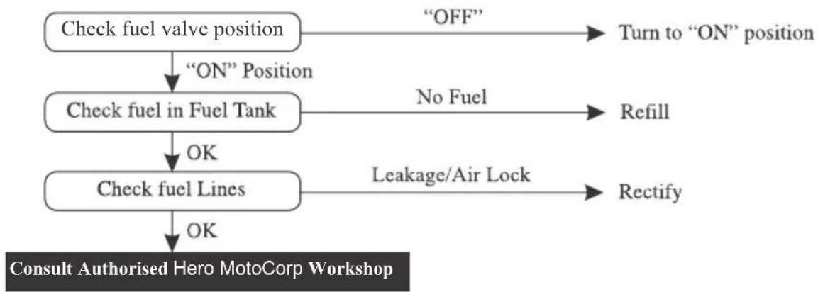
flowchart
graph TD
    A["Check fuel valve position"] -->|“ON” Position| B["Check fuel in Fuel Tank"]
    B -->|OK| C["Check fuel Lines"]
    C -->|OK| D["Consult Authorised Hero MotoCorp Workshop"]
    A -->|“OFF”| E["Turn to “ON” position"]
    B -->|No Fuel| F["Refill"]
    C -->|Leakage/Air Lock| G["Rectify"]
B. Electric Starter Not Working
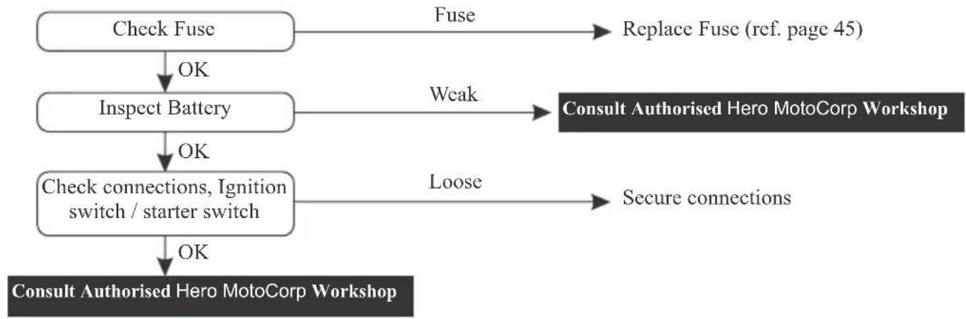
flowchart
graph TD
    A["Check Fuse"] -->|OK| B["Inspect Battery"]
    B -->|OK| C["Check connections, Ignition switch / starter switch"]
    C -->|OK| D["Consult Authorised Hero MotoCorp Workshop"]
    A -->|Fuse| E["Replace Fuse (ref. page 45)"]
    B -->|Weak| F["Consult Authorised Hero MotoCorp Workshop"]
    C -->|Loose| G["Secure connections"]
C. No Spark At Spark Plug
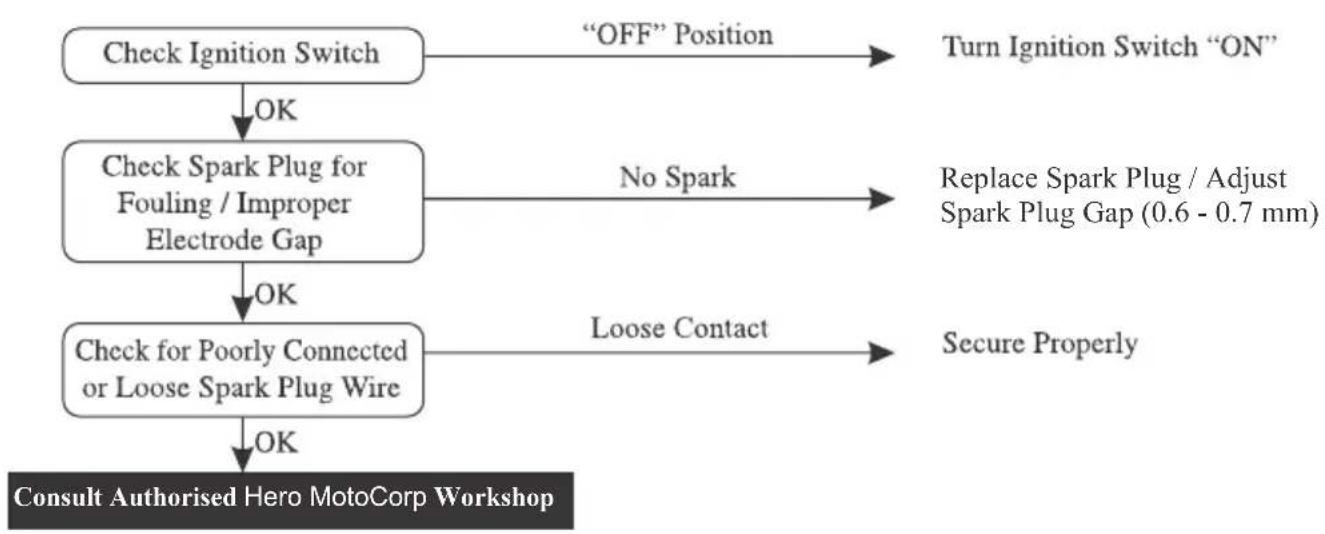
flowchart
graph TD
    A["Check Ignition Switch"] -->|OK| B["Check Spark Plug for Fouling / Improper Electrode Gap"]
    B -->|OK| C["Check for Poorly Connected or Loose Spark Plug Wire"]
    C -->|OK| D["Consult Authorised Hero MotoCorp Workshop"]
    A -->|“OFF” Position| E["Turn Ignition Switch “ON”"]
    B -->|No Spark| F["Replace Spark Plug / Adjust Spark Plug Gap (0.6 - 0.7 mm)"]
    C -->|Loose Contact| G["Secure Properly"]
- ENGINE STARTS BUT STALLS
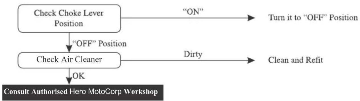
flowchart
graph TD
    A["Check Choke Lever Position"] -->|“ON”| B["Turn it to “OFF” Position"]
    A -->|“OFF” Position| C["Check Air Cleaner"]
    C -->|Dirty| D["Clean and Refit"]
    C -->|OK| E["Consult Authorised Hero MotoCorp Workshop"]
- POOR PICK-UP
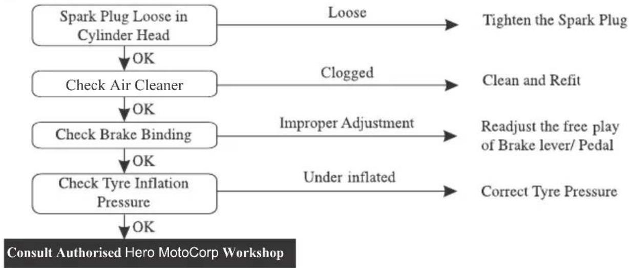
flowchart
graph TD
    A["Spark Plug Loose in Cylinder Head"] -->|OK| B["Check Air Cleaner"]
    B -->|OK| C["Check Brake Binding"]
    C -->|OK| D["Check Tyre Inflation Pressure"]
    D -->|OK| E["Consult Authorised Hero MotoCorp Workshop"]

    F["Tighten the Spark Plug"] --> A
    G["Clean and Refit"] --> B
    H["Improper Adjustment"] --> C
    I["Under inflated"] --> D

    J["Correct Tyre Pressure"] --> D
- ELECTRICAL SYSTEM
Feeble Horn Sound or No Light
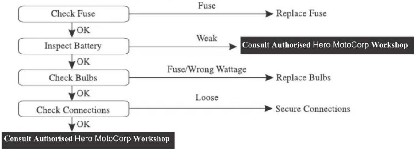
flowchart
graph TD
    A["Check Fuse"] -->|OK| B["Inspect Battery"]
    B -->|OK| C["Check Bulbs"]
    C -->|OK| D["Check Connections"]
    D -->|OK| E["Consult Authorised Hero MotoCorp Workshop"]

    F["Fuse"] --> G["Replace Fuse"]

    H["Weak"] --> I["Consult Authorised Hero MotoCorp Workshop"]

    J["Fuse/Wrong Wattage"] --> K["Replace Bulbs"]

    L["Loose"] --> M["Secure Connections"]

natural_image
Simple circular symbol with a diagonal line through it, representing no prohibition or exclusion (no text or numbers present)ROAD SIGNS
Mandatory signs: These road signs inform drivers/riders of the traffic rules that apply on a certain stretch of road, thereby instructing them on how to drive/ride. Mandatory signs are distinguished by the bright red circle with black and blue markings. It is imperative that all riders follow these signs as they help avoid accidents. Their violation can be penalised under the Motor Vehicle Act.
Mandatory

Stop

Give way
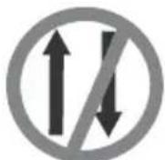
One way

No horn

No bicycles
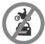
No automobiles
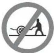
No hand cart

No pedestrians
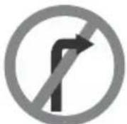
No right turn
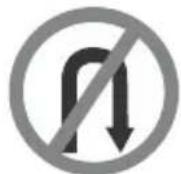
No 'U' turn

Overtaking prohibited
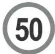
Speed limit

No stopping or standing

No parking

Length limit

Height limit
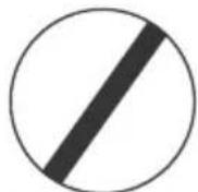
Restriction ends

Compulsory-ahead only

Compulsory-turn left

Compulsory-right ahead

Compulsory-ahead or turn right Compulsory-keep left

Compulsory-keep left

Compulsory-bicycle track

Compulsory-sound horn

natural_image
Simple gray triangle outline on white background (no text or symbols)Cautionary Signs: These signs inform the driver/rider of the road conditions ahead. Cautionary signs therefore serve as a warning. They are usually in a red triangle with black pictures on a white background. Illustrations, diagrams and symbols are used to forewarn about dangers ahead. Cautionary road signs are as important as mandatory signs. However, the violation of cautionary signs does not attract a penalty.
Cautionary
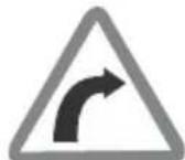
Right hand curve

Right reverse bend

Indine ahead
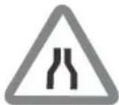
Narrow road ahead

Narrow bridge

Pedestrian crossing

School ahead
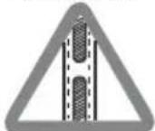
Gap in median

Cross road

Men at work

Roundabout

Hump Road

Informatory
Informatory Signs : These are facility signs that provide important information about road directions or maps of specific destinations. On highways, they provide information about the location of public telephones, restaurants, hospitals, parking, petrol pumps, resting-places and more. These signs are usually rectangular, with black or white pictures on a blue background.
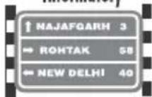
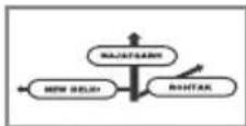
Destination Sign
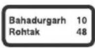
Re-assurance sign

Public Telephone
Petrol Pump
Hospital

First Aid Post

Eating Place

Light Refreshment
Place identification sign
Resting place

No through road

No through side road

Park this side
Parking both sides

Taxistand
Signs and Signals are language of the road. Learn them, respect them.
WARRANTY
Hero MotoCorp Ltd. (hereinafter called 'Hero MotoCorp') warrants its Splendor Pro vehicles, assembled/manufactured in its Plants and sold through its channel partners, to be free from any defect-both in material and workmanship, under normal use and conditions, subject to the following terms & conditions.
Terms & conditions
a) Splendor Pro vehicle is warranted for a period of 5 years or 70000 Km, whichever is earlier, from the date of purchase.
b) It is advised that the purchaser avails all free and paid services from the Hero MotoCorp's authorized workshop as per the recommended schedule, to be eligible for warranty benefits. Each paid service should be availed within 90 days from the date of previous service or as per the recommended schedule, whichever is earlier.
c) If any problem is observed in Splendor Pro vehicle, Hero MotoCorp's only obligation/ liability is to repair or replace that part/those parts which is/are considered to be the cause of such , problem provided however that such has not resulted due to misuse/improper handling etc. of problem the vehicle. Any Splendor Pro vehicle needing repair should be brought along with owner's manual to Hero MotoCorp's authorized workshop for necessary inspection and carrying rectification job.
LIMITATIONS OF WARRANTY
THE WARRANTY SHALL NOT APPLY-
(1) If all free services/paid services/oil top-ups are not availed as per the recommended schedule at Hero MotoCorp's authorized workshop.
(2) If any other engine oil which is non compatible with product is used other than SAE 10W30 SL Grade (JASO MA2).
(3) To normal wear & tear components including (but not limited to) brake shoes/pads, clutch plates, drive chain & sprockets, bulbs, electrical wiring, filter, spark plug, fasteners, shims, washers, oil seals, gaskets, rubber parts, bush, rubber bellows, plastic parts breakage and wheel rim for misalignment/bend.
(4) If additional wheel(s) is/are fitted and/or any other modification carried out/unauthorized accessories fitted which shall be responsible for malfunction/detoriation of the vehicle.
(5) If Splendor Pro vehicle has been used in any competitive events like races or rallies or for any commercial purposes as taxi etc.
(6) To any damage on vehicle's painted surface cropping due to industrial pollution or other external factors.
(7) For normal phenomena like noise vibration, oil seepage etc., which do not affect the performance of the vehicle.
(8) To any damage caused due to usage of improper oil/grease, non-genuine parts.
(9) If any defect crops or repairs needed as a result of using adulterated fuel.
(10) If any maintenance/repairs required due to bad road conditions or misuse of Splendor Pro vehicle.
(11) If any defect crops or repairs needed as a result of Splendor Pro vehicle meeting to some accident.
(12) For consumables like oil, grease, gasket etc to be used during free services and/or warranty repairs.
(13) To any part of the Splendor Pro vehicle which has been tampered or repaired in such a manner which has resulted in malfunction of the vehicle.
(14) For Splendor Pro vehicle not used in accordance with the guidelines given in this Owner's Manual.
(15) To proprietary items like Tyres, Tubes, Batteries etc, as they are subjected to the warranty terms & conditions of respective manufacturers and directly handled by them only.
(16) Any defect(s) developing on account of external factors such as environmental factors; including but not limited to fading/peeling/rusting of paint and/or stripes and/or plated parts, seat leather tearing & cracking, aluminium parts oxidation and cracking & discoloring of control switches etc. Decision regarding warranty settlement shall be taken by Hero MotoCorp and the same shall be final and binding on all concern.
Subject to DELHI JURISDICTION only.
BATTERY WARRANTY PERIOD
- 18 months from date of sale of vehicle or 20000 km. or
- 21 months from the date of charging (whichever is earlier).
- 3 months idle period is allowed from the date of charging to date of sale on vehicle.
Terms and condition of warranty
- Batteries are warranted against all defects in material and workmanship. Liability under this warranty is limited to making good of defects rising solely from the use of faulty material or workmanship during manufacturing and developing under proper use.
The warranty commences from the date of delivery to the original purchase of the vehicle.
-
In the event of any complaint the battery is to be returned complete with electrolyte to nearest battery service station or any OEM dealer. On inspection, battery would be returned or replaced.
-
This warranty card accompanies a battery sold as OEM fitment only. Claims should be supported with vehicle purchase invoice to enable processing.
-
The right to determine whether a battery needs repair or totally replacement lies with the company. In case where the battery is replaced, the defective battery becomes the property of the company and no scrap rebate will be given for it. The warranty period on the battery being repaired/replaced shall commence from the date of sale of the original battery as stated in the original warranty card.
-
All liabilities under this warranty will cease if the battery is used on the vehicle other than that on which the battery was originally fitted and on the expiry of the warranty period as mentioned above.
-
Recharging is not covered under the purview of this warranty and shall be billed as extra. However, FOC battery replacement/ repair includes cost of charging.
-
This warranty does not cover damage to the battery caused by faulty electrical systems, incorrect charging and filling, improper handling of the battery by unauthorized dealers/auto electricians, maintenance, willfull abuse, destruction by fire, collusion, theft or recharging.
-
Breakage of container and cover do not come under the purview of this warranty.
-
Adjudication and settlement of claim will take a couple of days as a battery has to be tested for the reported failure.
1.0 In case of tempering of the original wiring circuit in any manner whatsoever.
-
If a battery which is not recommended is fitted on the vehicle then such battery will not carry any warranty.
-
The applicable taxes which is leviable on the battery under repair or replacement will be borne by the customer.
-
Customers are deemed to have read, understood and agreed to these conditions at the time of purchase of the vehicle.
EMISSION WARRANTY
Scope of warranty
Hero MotoCorp Ltd. Warrants all its vehicles, assembled/manufactured at its various Plants and sold through its Authorised dealers, to comply with emission standards as specified in S.No. 5 of table in item(i) of sub rule (2) of Rule 115 of Central Motor Vehicles Rules, 1989, which stipulates that "Idle CO (Carbon monoxide) emission limit for all two wheeled petrol driven vehicles shall not exceed 3.0 percent by volume and HC (Hydro Carbon) 3000 ppm, subject to following terms & conditions.
Terms & conditions
a) The emission warranty shall be applicable in India and shall remain valid for a period of 3 years or 30000 kms, whichever occurs earlier, from the date of vehicle purchase.
b) In case any defect is observed in any emission-related component, Hero MotoCorp only obligation/liability shall be to repair and/or replace those part (s) which is/are considered to be the cause of non-compliance with the emission standards.
c) The emission warranty shall be applicable only to those vehicles, which are being regularly maintained at Hero MotoCorp Authorised Dealers/Service Points in accordance with the maintenance schedule provided in the owner's manual.
d) The customer should follow the recommended parts replacement as per the maintenance schedule in order to avail the emission warranty.
e) If any part (s) related to emission characteristics of the vehicles is/are tampered and/or repaired by unauthorised person/workshops etc, then the emission warranty shall stand cancelled.
f) Any part (s) suffering wear and tear under the normal course of running shall not be covered under the emission warranty. Therefore, all such parts should be replaced by the customer from time to time, on payment basis, as per the maintenance schedule provided in owner's manual and dealer's advice.
g) It is recommended to avail the services as per the recommended schedule to be eligible for the emission warranty benefits. Please ensure that each paid service is availed within 90 days from the date of previous services or as per the recommended schedule, whichever is earlier. All service details should be completely filled by the dealer, in the Service Record Sheet given in the owner's manual.
h) It is mandatory to obtain a PUC certificate from the Authorised PUC center. In case of non-compliance with the emission standards please contact the channel partner/authorised workshop immediately alongwith the previous OK certificate, for the necessary rectification. The manufacturer or the dealer is not responsible for any penalty levied on you on account of non-compliance with the emission standards.
i) All decisions regarding emission warranty settlement shall be taken by Hero MotoCorp Ltd. and shall be final binding on all concerned.
Subjected to Delhi jurisdiction only.
Hero
GENUINE PARTS
WHAT ARE THE BENEFITS OF HERO MOTOCORP GENUINE SPARE PARTS ?
▶ Assures long life
▶ Ensures economy for a long time
▶ Safety of vehicle and rider
▶ Peace of mind
▶ Value for money
▶ Assured quality

GENUINE PARTS
CONSEQUENTIAL DAMAGES ON USING NON-GENUINE PARTS
| Clutch Plate | ▸ Material used is inferior▸ Damages other parts of clutch like, clutch center and outer clutch▸ Affects fuel efficiency▸ Poor acceleration |
| Cam Chain Kit | ▸ Poor performance▸ Reduced life |
| Gasket Cylinder Head | ▸ Improper sealing▸ Engine knocking▸ Leads to leakage and smoky exhaust▸ Higher emission level |

GENUINE PARTS
CONSEQUENTIAL DAMAGES ON USING NON-GENUINE PARTS
| Element Air Cleaner | ▸ Improper air filtration resulting in premature engine failure▸ Affects fuel efficiency▸ Poor engine performance |
| Spark Plug | ▸ Frequent stalling of engine▸ Higher emission level▸ Poor engine performance▸ Affects fuel efficiency |
| Brake Pads / Shoes | ▸ Poor braking efficiency▸ Rider safety - an issue▸ Discs / Drum wear out, resulting in subsequent repair cos |
| Chain Sprocket Kit | ▸ Noisy Operation▸ Failure of chain can cause fatal accident |
ZONAL/REGIONAL/AREA OFFICES
For any of your service related query/requirements you may contact the respective Zonal/Regional/Area Offices
CENTRAL ZONE
Hero MotoCorp Ltd., No. 209-210, Ganpati Plaza, M.I. Road, Jaipur-302001, (Rajasthan). Tel: +91 141 2389031, +91 141 2389156, E-mail: jaipur@heromotocorp.com
Hero MotoCorp Ltd., Office No. 705-706, 7th Floor, Fun Square, Durga Nursery Road, Udaipur -313001 (Rajasthan). Tel: +91 0294-2980578, 79, E-mail: udaipur@heromotocorp.com
Hero MotoCorp Ltd., Office. No.401, 4th Floor, Offizo, Magneto Mall, Labhandi, G.E. Road, Raipur -492001, (Chhattisgarh) Tel: +91-771-4034749, E-mail: raipur@heromotocorp.com
Hero MotoCorp Ltd., Third Floor, Alankar Palace, Plot No. 11, Zone II, M.P. Nagar Bhopal-462011, India. Tel: +91-755-4203160, 2553697, 4272429, 2550086, E-mail: bhopal@heromotocorp.com
Hero MotoCorp Ltd., Maloo-01, 601-602, 6th Floor, Plot No. 26C, Scheme No. 94, Ring Road, Indore, M.P.-452010, Tel: +91-731-4978269, 70, E-mail: indore@heromotocorp.com
EAST ZONE
Hero MotoCorp Ltd., Flat No: 1002. 10th Floor, Martin Burn Business Park, BP3, Salt Lake, Sector-V, Kolkata-700091, West Bengal, India. Tel : +91-33-44026841,+91-33-44026830, E-mail : kolkata@heromotocorp.com
Hero MotoCorp Ltd, Odysa Business Centre, Plot no. 30, 30/982, 172/1030, 4th Floor Cuttack, Bhubaneshwar highway road, Rasulgarh, Bhubaneswar-751010, Odisha, India. Tel: +91-674-2581161, 62, 63, 64, E-mail: bhubaneshwar@herome
Hero MotoCorp Ltd., Yash Heights, 1st Floor Bariatu Road, Above Basudeb Tata Showroom Ranchi-834009, Jharkhand, India. Tel: +91-651-2542222, 2542224, 2542225, E-mail: ranchi@heromotocorp.com
Hero MotoCorp Ltd., Sai Corporate Park, A Block, 6th Floor, Rukanpura, Bailey Road Patna, Bihar – 800014 Tel: +919334280555/7004569648 E-mail: patna@heromotocorp.com
NORTH ZONE
Hero MotoCorp Ltd., 3rd Floor, Tower-A, DLF Centre Court, Sector-42, Golf Course Road, DLF Phase 5, Gurgaon -122002, Haryana, India. Tel: 0124-4754800, E-mail: delhi@heromotocorp.com
Hero MotoCorp Ltd., 602, 6th Floor, Office Tower-1, Plot No BW58, Logix City Center, Sector-32, Noida - 201301. Tel: 0120-4631000, E-mail: noida@heromotocorp.com
Hero MotoCorp Ltd., S.C.O-367-368, First Floor, Sector-34A, Chandigarh-160022, India. Tel: +91-172-2623773, 2623774, 2623775, E-mail: chandigarh@heromotocorp.com
Hero MotoCorp Ltd., Kapoor Towers, Plot No-284, 15-B, Rajpur Road, Dehradun-248001, India. Tel:0135-2714661,2713662,2714663, E-mail: dehradun@heromotocorp.com
otocorp.c
ZONAL/REGIONAL/AREA OFFICES
NORTH ZONE
Hero MotoCorp Ltd., Summit Building (10th Floor) Plot No TCG 3/3 Vibhuti Khand, Gomti Nagar Lucknow - 226010, India. Tel: 0522-4006594, E-mail: lucknow@heromotocorp.com
Hero MotoCorp Ltd., C-19/134-B ,Third Floor I .P Grand, Lallapura, Sigra, Varanasi, Uttar Pradesh - 221010, India. Tel: +91- , E-mail: varanasi@heromotocorp.com0542- 2390949,2390241
SOUTH ZONE
Hero MotoCorp Ltd., SKAV 909, 3rd Floor, 9/1, Lavelle Road, Bangalore-560001, India. Tel: +91-80-46881000, E-mail: bangalore@heromotocorp.com
Hero MotoCorp Ltd., 3-6-289, 3rd Floor, Kareem Manzil, Hyderguda, Hyderabad-500029, India. Tel: +91-40-23223735, 23223727, 23223570, E-mail: hyderabad@heromotocorp.com
Hero MotoCorp Ltd., 9th Floor Seshachalam Centre No.636/1. Anna Salai, Nandanam, Chennai-600035, India. Tel: +91-44-24340974, 24340977, 24340978, E-mail: chennai@heromotocorp.com
Hero MotoCorp Ltd., 6-A, DD Trade Tower, (6th Floor), Kaloor-Kadavanthra Road, Kaloor-682 017, Kochi-682017, India. Tel: +91-0484-4039646 -7, E-mail: cochin@heromotocorp.com
Hero MotoCorp Ltd., No 1547, 2nd Floor Classic Towers, Trichy Road, Coimbatore - 641018 Tel: +91-422-2200058, 2200061, E-mail: coimbatore@heromotocorp.com
Hero MotoCorp Ltd., First Floor VA Kalburgi Mahalakshmi Mansion, Mandakini Hospital Road, New Cotton Market, Hubli-580029, India. Tel: 0836-2269717, 2361038, E-mail: hubli@heromotocorp.com
Hero MotoCorp Ltd., D.NO. 54-11-18 E, 2nd Floor, Sai Oddessey Building, Opp Executive Club, Near NH-5, Vijayawada-520008, Andhra Pradesh, India. Tel: +91-866-2546859, 2546860, E-mail: vijayawada@heromotocorp.com
WEST ZONE
Hero MotoCorp Ltd., Chrome Building, Sr. No. 33, Hissa-A-1/1/2, Plot - 2, Viman Nagar Avenue 2, Nagar Road, Pune-411014, India. Tel: +91-020-71903500, E-mail: pune@heromotocorp.com
Hero MotoCorp Ltd., 603-604, Gunjan Tower, Off Alembic Gorwa Road, Baroda-390023, India. Tel: +91-265-2286569/2286570, E-mail: baroda@heromotocorp.com
Hero MotoCorp Ltd., Ground Floor, Block No.2, Vishnu Vaibhav Complex, 222, Palm Road, Civil Lines, Nagpur-440001, India. Tel: +91-712-2545990-91, E-mail: nagpur@heromotocorp.com
Hero MotoCorp Ltd., Astarc House-Third Floor, 76/79, Makwana Lane, Off. Andheri-Kurla Road, Andheri (East), Mumbai-400059, India. Tel: +91-22-28562071, E-mail: mumbai@heromotocorp.com
Hero MotoCorp Ltd., 604, Kings Plaza, Astron Chowk, Rajkot, Gujarat - 360001 Tel: 0281-2460622, 2460623, E-mail: rajkot@heromotocorp.com
- NOTE
- MOTORCYCLE IDENTIFICATION
- VIN and Engine No. may be required:
- SAFE RIDING TIPS
- Do's:
- Hero RideSafe
- Don't:
- ACCESSORIES & MODIFICATIONS
- WARNING
- Accessories
- Modifications
- TIPS FOR HEALTHY ENVIRONMENT
- PARTS LOCATION
- PARTS FUNCTION
- INSTRUMENTS AND INDICATORS
- IGNITION SWITCH
- LEFT HANDLEBAR CONTROLS
- Passing switch
- Headlamp switch
- Dimmer switch
- Turn signal lamp switch
- Horn switch
- STARTER SWITCH
- CLUTCH SWITCH
- CAUTION
- STEERING LOCK
- HELMET LOCK
- SIDE STAND INDICATOR
- SIDE STAND SWITCH
- FUEL VALVE
- OFF
- ON
- RES
- FUEL TANK
- ENGINE OIL
- BRAND: Hero 4T plus GRADE: SAE 10W 30 SL Grade (JASO MA2).
- OIL CAPACITY : 0.95 litre
- ENGINE OIL LEVEL CHECK
- ENGINE OIL TOP UP PROCESS
- ENGINE OIL REPLACEMENT PROCESS
- TYRES
- Air Pressure
- Inspection
- Tread Wear
- Unidirectional Tyres
- PRE - RIDE INSPECTION
- STARTING THE ENGINE
- NOTE :
- Flooded Engine
- Running In
- RIDING
- Recommended Shifting Speed
- BRAKING
- PARKING
- ANTI-THEFT TIPS
- UTILITY BOX
- TOOL KIT
- FIRST AID KIT
- SAFETY PRECAUTIONS
- MAINTENANCE
- MAINTENANCE SCHEDULE
- OIL FILTER SCREEN & CENTRIFUGAL FILTER
- SPARK PLUG
- AIR CLEANER
- THROTTLE OPERATION Cable Inspection
- Free Play Adjustment
- VALVE CLEARANCE
- Standard clearance
- CARBURETOR
- Idle speed
- CLUTCH
- Other Checks
- DRIVE CHAIN
- Adjustment
- Lubrication
- FRONT BRAKE
- REAR BRAKE
- BRAKE WEAR INDICATORS
- BATTERY
- Location
- Specification
- Battery charging
- Battery storage
- Battery removal
- Battery installation
- FUSE REPLACEMENT
- STOP LAMP SWITCH
- SIDE STAND
- HEADLAMP ADJUSTMENT
- SUSPENSION
- Rear Shock Absorber Adjustment
- FRONT WHEEL REMOVAL
- Installation Notes
- REAR WHEEL REMOVAL
- WASHING THE MOTORCYCLE
- CATALYTIC CONVERTER
- AIR SUCTION VALVE
- BASIC TROUBLESHOOTING
- STARTING TROUBLE - ENGINE DOES NOT START
- Fuel System
- Electric Starter Not Working
- ROAD SIGNS
- WARRANTY
- Terms & conditions
- LIMITATIONS OF WARRANTY
- THE WARRANTY SHALL NOT APPLY-
- BATTERY WARRANTY PERIOD
- Terms and condition of warranty
- EMISSION WARRANTY
- Scope of warranty
- Hero
- GENUINE PARTS
- WHAT ARE THE BENEFITS OF HERO MOTOCORP GENUINE SPARE PARTS ?
- ZONAL/REGIONAL/AREA OFFICES
- For any of your service related query/requirements you may contact the respective Zonal/Regional/Area Offices
- CENTRAL ZONE
- EAST ZONE
- NORTH ZONE
- SOUTH ZONE
- WEST ZONE
Brand : HERO
Model : Splendor Pro (2013)
Category : Motorcycle