
EC74GTB - Cooker Euromaid - Free user manual and instructions
Find the device manual for free EC74GTB Euromaid in PDF.


| Product Type | Freestanding Gas Cooker |
| Brand | Euromaid |
| Model | EC74GTB |
| Width | 74 cm |
| Height | 90 cm |
| Depth | 60 cm |
| Weight | 55 kg |
| Power Supply | 220-240 V ~ 50 Hz |
| Gas Connection | Natural Gas or LPG (conversion kit included) |
| Number of Gas Burners | 4 (including one triple-ring wok burner) |
| Oven Type | Electric Fan-Forced Oven with Grill |
| Oven Capacity | 65 L |
| Oven Functions | Fan Bake, Grill, Fan Grill, Defrost, Light |
| Grill Element | Built-in, 2.0 kW |
| Control Panel | Front-mounted knobs with integrated ignition |
| Door Type | Drop-down door with tempered glass |
| Cleaning | Removable door inner glass, enamel cavity |
| Safety Features | Flame failure safety device on all gas burners |
| Child Lock | Oven door lock |
| Installation Type | Freestanding |
| Energy Rating | Gas: 3-star, Oven: 4-star |
Frequently Asked Questions - EC74GTB Euromaid
User questions about EC74GTB Euromaid
0 question about this device. Answer the ones you know or ask your own.
Ask a new question about this device
Download the instructions for your Cooker in PDF format for free! Find your manual EC74GTB - Euromaid and take your electronic device back in hand. On this page are published all the documents necessary for the use of your device. EC74GTB by Euromaid.
USER MANUAL EC74GTB Euromaid
Eclipse Series Gas Cooktops
EC64GS
60cm 4 burner gas cooktop - stainless steel
EC64GB
60cm 4 burner gas cooktop - black glass
EC74GTB
75cm 4 burner gas cooktop, twin wok - black glass
EC95GLS
90cm 5 burner gas cooktop - stainless steel
EC95GLB
90cm 5 burner gas cooktop - black glass
Contents
For your safety
Installation....3
During use....4
Safety of children and the infirm 6
Service and repairs 6
Environmental protection advice....6
Use and Care
Description of the hob 7
Instructions for use 8
To Light the Burners 9
For correct use of the hob 11
Cleaning and maintenance 12
Abnormal Operation 14
Service and spare parts 14
Warranty 14
Installation
Technical data 15
Instructions for Installation....15
Building into kitchen benches 16
Combustible surfaces 16
Installation cutout drawings....17
Connection to the gas supply 20
Electrical connection 21
Replacing the power supply lead....21
Before leaving 22
Wiring Diagrams 23
Gas Conversion (NG to ULPG) 24
Gas Conversion (ULPG to NG) 25
Troubleshooting....26
Warranty 29
For Your Safety
These instructions have been drawn up for your safety and that of others. You are therefore requested to read them carefully before installing and using the appliance. Keep this instruction manual for future reference as necessary. If the appliance is sold or moved, make sure that the manual is handed over to the new user.
INSTALLATION
- Installation of the appliance and its connection to the electrical mains must only be carried out by Authorised Personnel. Before any service procedure, it is important to check that the appliance is DISCONNECTED from the electrical mains.
- WARNING: This appliance is a domestic kitchen appliance suitable for indoor installation. It is not suitable for outdoor installations such as alfresco kitchens or garages unless a qualified, competent installer has deemed the location and installation to be suitable & compliant.
• DO NOT MODIFY THIS APPLIANCE. - After removing the appliance from the packaging, make sure that it is undamaged and that the electrical lead is in perfect condition. Otherwise, contact your dealer before operating the appliance.
- Make sure that air is able to circulate freely around the appliance. Poor ventilation produces a shortage of oxygen.
- Make sure that the available gas supply matches the type of gas indicated on the data label and the gas type label next to the gas connection point.
- Use of a gas cooking appliance produces heat and moisture in the room in which it is installed. Ensure that the room is well ventilated by keeping the air intakes open and in good working order or by installing an extractor hood with discharge pipe.
- If the appliance is used intensively for a long time the effectiveness of the ventilation will have to be increased, for example by opening a window or increasing the power of any electric extractor fan.
For Your Safety
DURING USE
- This product is designed to cook foods inside private homes and for non-commercial purposes. It should not be used for any other purpose.
- After using the appliance, make sure that all controls are in 'CLOSED' or 'OFF' position.
- If you use an electrical socket close to this appliance, take care that the cables of the appliances you are using do not touch it and are far enough away from the hot parts of this appliance.
• DO NOT SPRAY AEROSOLS IN THE VICINITY OF THIS APPLIANCE WHILE IT IS IN OPERATION.
• DO NOT STORE OR USE FLAMMABLE LIQUIDS OR ITEMS IN THE VICINITY OF THIS APPLIANCE. - NOT FOR USE IN MARINE CRAFT, CARAVANS OR MOBILE HOMES UNLESS EACH BURNER IS FITTED WITH FLAME SAFEGUARD.
- WHERE THIS APPLIANCE IS INSTALLED IN MARINE CRAFT OR IN CARAVANS, IT SHALL NOT BE USED AS A SPACE HEATER.
- WARNING - Accessible parts will become hot when in use. To avoid burns and scalds children should be kept away.
- This appliance is not intended for use by young children or infirm persons without supervision
- Young children should be supervised to ensure they do not play with the appliance.
For Your Safety
During use (continued)
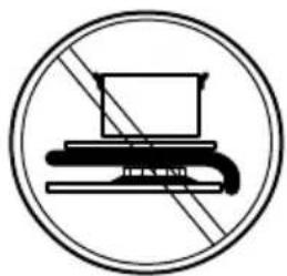
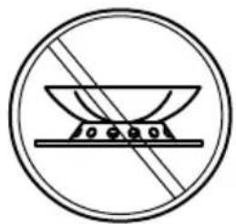
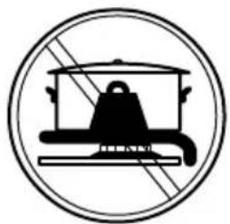
- Explanation of symbols on the glass top. (For Gas on glass models only)
natural_image
Prohibition sign depicting a laptop with a keyboard and monitor, crossed out by diagonal lines (no text or symbols)Do not place anything, eg. flame tamer, asbestos mat, between pan and pan support as serious damage to the appliance my result.
natural_image
Prohibition sign of a cooking pot with crossed lines indicating resistance (no text or symbols)Do not remove the pan support and enclose the burner with a wok stand as this will concentrate and deflect heat onto the hotplate.
natural_image
Symbol of a cooking pot with diagonal lines indicating no cooking restrictions (no text present)Do not use large pots or heavy weights which can bend the pan support or deflect flame onto the hotplate.
For Your Safety
Safety of children and the infirm
This appliance must only be used by adults. Make sure that children do not touch the controls or play with the appliance.
The exposed parts of this appliance heat up during cooking and remain hot for some time even after it is switched off. Keep children well away until the appliance has cooled down.
Cleaning and maintenance
Keep the appliance thoroughly cleaned. Food residues may cause fire risks.
Service and repairs
If the appliance fails to operate correctly, never attempt to repair the appliance yourself. Repairs by unskilled persons may cause damage and accidents. First refer to the contents of this manual. If you do not find the necessary information, contact your nearest Service Center. Servicing work on this appliance must be carried out by Authorised Personnel. Always request the use of original spare parts.
For Service & Spare Parts please contact: 1300 556 816 (AU) or 09 274 8265 (NZ)
Environmental protection advice
All the materials used are environmentally friendly and recyclable. Please make your contribution to conserving the environment by using the separate waste collection channels available when disposing of this product. Through environment-friendly disposal, a number of materials used in the production of your appliance can be recycled. Find out about the current disposal options from your local authority.
Use and Care
Description of the hob
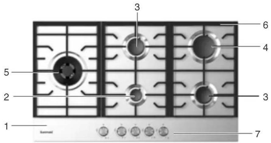
- Hob
- Auxiliary burner
- Semi-rapid burner
- Rapid burner
- Wok burner
- Pan supports
- Control knobs
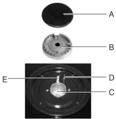
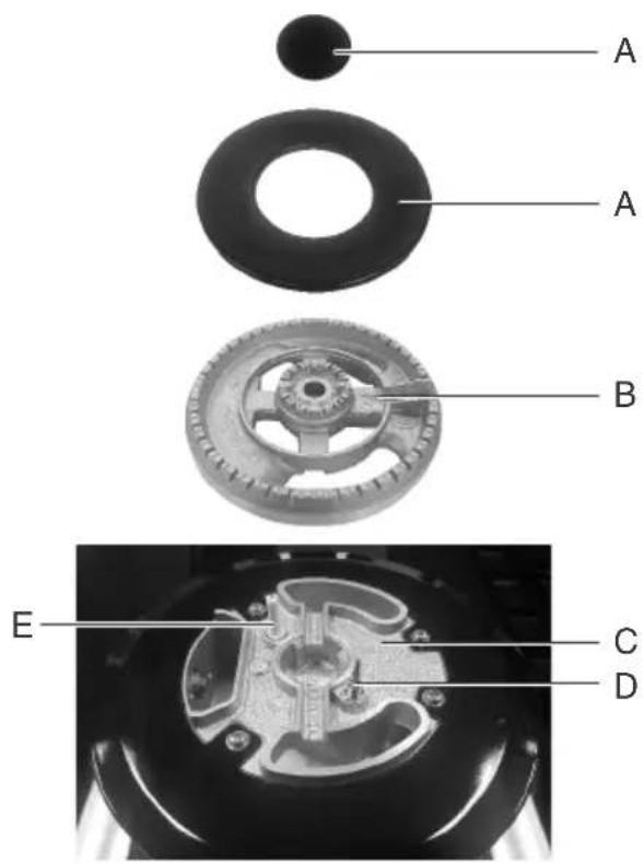
Note: Model shown may not be identical to the hotplate you have purchased.
A - Burner cap
B - Burner head
C - Burner bowl
D - Thermocouple
E - Ignition Candle
Use and Care
Instructions for use
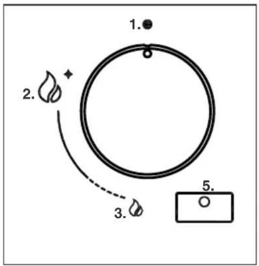
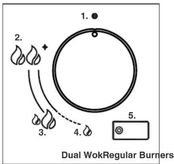
The symbols on the control knobs mean the following:
Regular burners (Auxiliary, Semi Rapid, Rapid, Wok)
- No gas flow or 'Off' position.
- Maximum gas flow or 'High' flame and lighting position.
- Minimum gas flow or 'Low' flame position.
Dual Valve Wok burner (Not all models)
-
No gas flow or 'Off' position.
-
Maximum gas flow for inner and outer flame or 'High' flame and lighting position.
-
Minimum gas flow for outer flame only or 'Low' flame position. NOTE: Inner flame remains in 'High' position at this point.
-
Minimum gas flow for inner flame or 'Low' flame position. No outer flame.
All burners
- Position of the burner each control knob operates.
All operating positions must be set between the maximum and minimum flow settings, and never between the maximum setting and the closed position.
Use and Care
To light the burners
To light the burner, press the control knob down completely and hold down before rotating anti-clockwise to the 'High' Flame position. The ignition device is integrated into the control knob and is automatically activated by pushing down on the control knob.
After lighting the flame, keep the knob pressed for about 5 seconds: this time is necessary to heat up the thermocouple (D on page 7) and activate the safety valve, which would otherwise cut off the gas flow.
In the instance of a power failure, place a lit match near the burner and proceed as described above. If the flame does not light after the first attempt, wait 5 minutes for the gas to dissipate before attempting to re-light the burner.
Once lit, check that the flame is even and turn the control knob to adjust the flame as required. If the flame is uneven, check that the 'burner head/skirt' and 'burner cap' are correctly positioned. To turn off the flame, turn the control knob clockwise to the 'Off' position (●). Before removing pots or pans from the burners, always turn off the flame.
Use and Care
Using the Dual Valve Wok burner (not all models)
The Dual Valve Wok burner has the advantage of providing both very high or very low heat when needed.
The powerful Dual Flame provides high heat when frying, boiling or searing is required. It can also be turned to the lowest point where only the small inner flame remains alight to provide a low heat for simmering or keeping the dish warm.
Follow the instructions below to light the burner.
When turning the flame down from the 'High' position (2) to the 'Low' position (3) only the outer flame turns down.
After this point, the outer flame turns off and the inner flame begins to turn down until it reaches the 'Low' flame position (4).
When turning the flame up again, the outer flame automatically relights starting in the 'Low' position (3).
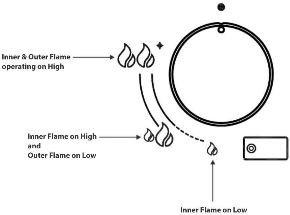
flowchart
graph TD
    A["Inner & Outer Flame operating on High"] --> B["Flame with flame icon"]
    C["Inner Flame on High and Outer Flame on Low"] --> D["Flame with flame icon"]
    E["Inner Flame on Low"] --> F["Flame with flame icon"]
Use and Care
For correct use of the hob
For lower gas consumption and better efficiency, use only flat-bottomed pans of dimensions suitable for the burners, as shown in the table below. Also, as soon as a liquid comes to the boil take care to turn the flame down to a level that will just keep it boiling.
Burner Minimum diameter Maximum diameter
Large (rapid) 180mm 220mm
Medium (semi-rapid) 120mm 200mm
Small (auxiliary) 80mm 160mm
Wok 220mm 260mm

The pan supports get hot during normal usage, take care when operating the control knobs close to the pan supports.
DO NOT use foil on any part of the burners, pan supports or hob. This is extremely dangerous and can cause explosions.
DO NOT leave cooking unattended. Fats or oils may catch fire if overheated. Boil overs may cause damage to the cooktop if not contained immediately.
Using pans which are too large for a particular burner may cause higher temperatures on other surfaces such as control knobs. Please see the sizing guide for pans above.
Use and Care
Cleaning and maintenance
Before cleaning, disconnect the appliance from the electrical mains, make sure all burners are 'off' and allow the hotplate to cool down.
General cleaning
Wash enameled parts with lukewarm water and detergent: do not use abrasive products which might damage them. Wash the burner caps and head/skirts often with hot water and detergent, taking care to remove all deposits. Ensure the burner ports in the head/skirts are clear and are not blocked by water or detergent. The hob pan stands can also be washed in a dishwasher. For stubborn dirt, use ordinary non-abrasive detergents or specific commercial products. We strongly advise not to use scouring pads, steel wool or acids for cleaning. Do not steam clean this appliance. Take care when cleaning the hob with liquids. Water ingress can damage the internal components.
Stainless steel hob
Clean the hob regularly with a moistened soft cloth, lukewarm water and a little liquid detergent. Always wipe stainless steel with the grain to avoid scratching from possible grit in the cloth. If the hob gets very dirty, use specific commercial products for Stainless Steel. Do not use the following products:
- Abrasive or harsh household detergents or bleaches
- Soaped scouring pads which are not suitable for non-stick utensils
• Steel wool scouring pads
• Stain removers for baths or sinks - Metal polish
Glass hob
Clean the hob regularly with a moistened soft cloth, lukewarm water and a little liquid detergent. If the hob gets very dirty, use specific commercial products for glass. Do not use the following products:
- Abrasive or harsh household detergents or bleaches
- Soaped scouring pads which are not suitable for non-stick utensils
• Steel wool scouring pads
• Stain removers for baths or sinks
Use and Care
Ignition plug
Automatic burner ignition is provided by a ceramic 'plug' and a metal electrode (Ignition Candle - E on page 7). Periodically clean these parts of the hob thoroughly. In addition, to avoid ignition difficulties, check that the cavities in the burner are not obstructed. To remove deposits from the burner cavities, remove the burner caps. After cleaning, put the burner heads and caps back together and return them correctly to their position. After washing, replace the pan supports, checking that they are correctly positioned.
Use and Care
Routine maintenance
Have the condition and efficiency of the gas pipe and the pressure regulator (if installed) checked periodically. If anomalies are found, do not repair components but have the faulty component replaced. To ensure good performance and safety, the gas regulator taps must be greased periodically.

Periodic lubrication of the taps and any other appliance service must only be carried out by Authorised Personnel.
Abnormal operation
Any of the following are considered to be abnormal operation and may require servicing:
• Yellow tipping of the burner flame.
- Sooting up of cooking utensils.
- Burners not igniting properly.
- Burners failing to remain alight.
- Burners extinguished by cupboard doors.
• Gas valves, which are difficult to turn.
Please read the troubleshooting tips on page 25 before contacting Glen Dimplex.
Service and parts
Before leaving the factory, this appliance was tested and adjusted by specialist skilled staff to give the best operating results. Any subsequent necessary repairs or adjustments must be carried out with the greatest care and attention by authorised personnel. For this reason, we strongly advise you contact the Glen DImplex Service Center, specifying the nature of the problem, the model of the equipment and the serial number. This data is provided on the data label adhered to the base of the appliance and on the duplicate data label. Always use original spare parts.
Warranty
Your new appliance is covered by a warranty. The details of your warranty conditions are on your Warranty Card supplied in the rear of this manual. Keep the physical receipt which documents your purchase of the appliance and purchase date as you will need to show this for any Warranty repairs. Warranty cannot be claimed without proof of purchase. When the appliance has been provided by a builder, the certificate of occupancy is acceptable as proof of purchase.
Installation
Technical data
• Gas intake connection 1/2" BSP
• Electricity supply 240V AC (50Hz)
| Burner Type | Natural Gas: 1.0 kPa | ULPG: 2.75 kPa | ||
| Injector (mm) | Nominal Gas Rate | Injector (mm) | Nominal Gas Rate | |
| Auxiliary | 0.90 | 3.9 MJ/h | 0.53 | 3.3 MJ/h |
| Semi Rapid | 1.18 | 6.6 MJ/h | 0.70 | 6.1 MJ/h |
| Rapid | 1.55 | 10.8 MJ/h | 0.90 | 10.0 MJ/h |
| Wok single 4KW | 1.80 | 12.0 MJ/h | 1.00 | 12.2 MJ/h |
| Wok Dual 5KW | 1.80 (outer)0.80 (inner) | 15.8 MJ/h (total)2.6 MJ/h (inner) | 0.90 (outer)0.46 (inner) | 12.2 MJ/h (total)2.2 MJ/h (inner) |

Instructions for installation
This appliance shall be installed only by authorised persons and in accordance with the manufacturer's installation instructions, local gas fitting regulations, municipal building codes, electrical wiring regulations, AS/NZS 5601 - Gas Installations and any other statutory regulations.
Data Label - The Data Label is located on the bottom of the appliance. A duplicate Data Label is supplied to adhere in an accessible area next to the appliance or on this user manual. This appliance is suitable for Natural Gas and ULPG; ensure that the available gas supply matches the Data Label and gas type label.
Ventilation - Ventilation must be in accordance with AS/NZS5601-Gas Installations. In general, the appliance should have adequate ventilation for complete combustion of gas, proper flueing and to maintain temperature of immediate surroundings within safe limits.
Before any procedure, it is important to check that the appliance is DISCONNECTED from the electrical mains. The Manufacturer declines all responsibility for any damage deriving from installations in breach of the regulations in force or from failure to comply with these installation instructions.
For 90cm models - When installed above a cupboard or drawer, a protective shelf/shield must be installed at a minimum of 10mm below the cooktop to insure the base of the cooktop cannot be accidentally touched when hot. The shield does not need to be a non-combustible material. Material such as timber or melamine can be used. The shield needs to be easily removable for servicing of the appliance. A small gap (10-20mm) should be left at the front and rear to allow sufficient ventilation to the cooktop.
Installation
Building into kitchen benches
These hobs are designed for installation in kitchen benches. When installed into a corner, the walls or panels above the benchtop must be at least 155mm away from the edge of the hob to ensure adequate air circulation to the burners.
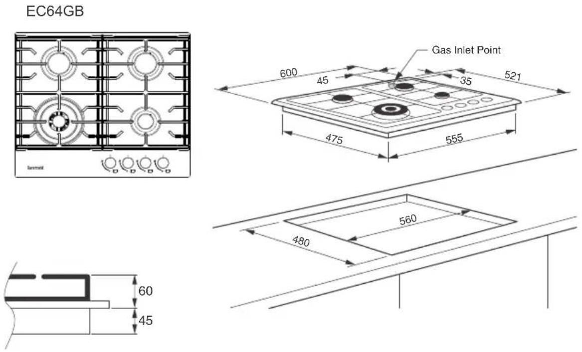
The dimensions of each hob and installation openings are shown in the illustrations included on the following pages.
Insertion and fixing
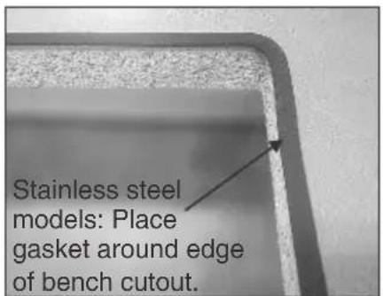
Before inserting the hob in the installation opening, the supplied gasket must be fitted. It is important to fix this gasket evenly, without gaps or overlapping, to prevent liquid from seeping underneath the hob.
1) Provide a cut-out in the benchtop as close as possible to the dimensions included on the following pages.
2) Make sure the benchtop is clean and dry.
3) Stainless steel models - Attach the gasket to the benchtop as close as possible to the edge of the cut-out.
Glass models - Attach the gasket to the underside edge of the glass.
NOTE: The join should be at the rear of the cooktop.
4) Place the hob in the installation opening and push it down so that the hob is resting firmly on the benchtop.
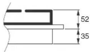
5) Fit the supplied brackets and screws as shown in the illustrations to
the right. There are several combinations
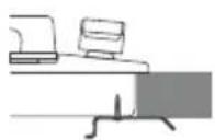
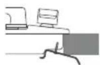
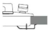
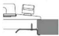
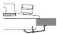
that can be used depending on the thickness of the benchtop.
Tighten the screws to secure the hob to the benchtop. Make sure the hob is sitting flat and even. Adjust where necessary.
Combustible Surfaces as per AS/NZS 5601
Any adjoining wall surface situated within 200mm from the edge of any hob burner must be a suitable non-combustible material for a height of 150mm for the entire length of the hob.
Install Range Hoods and Exhaust Fans in accordance with the manufacturer's instructions, no closer than 600mm above the highest part of the cooking surface for Range Hoods and 750mm for Exhaust Fans.
Installation
Installation Cutout Drawings
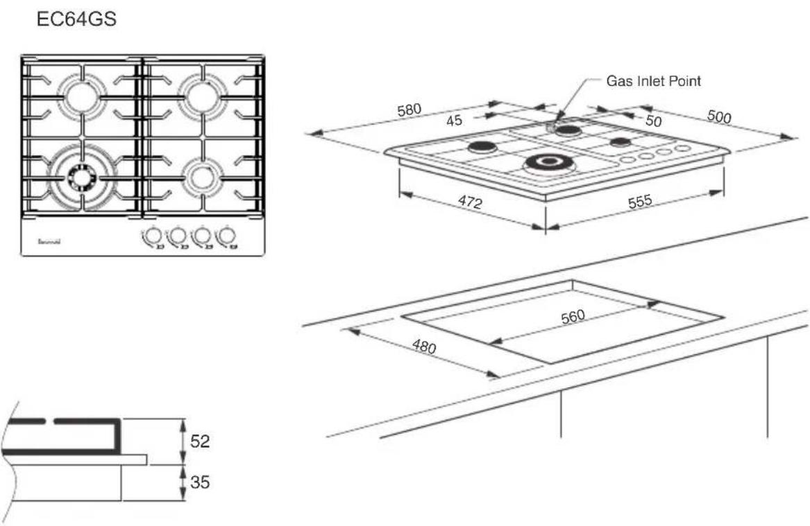
Installation
Installation Cutout Drawings
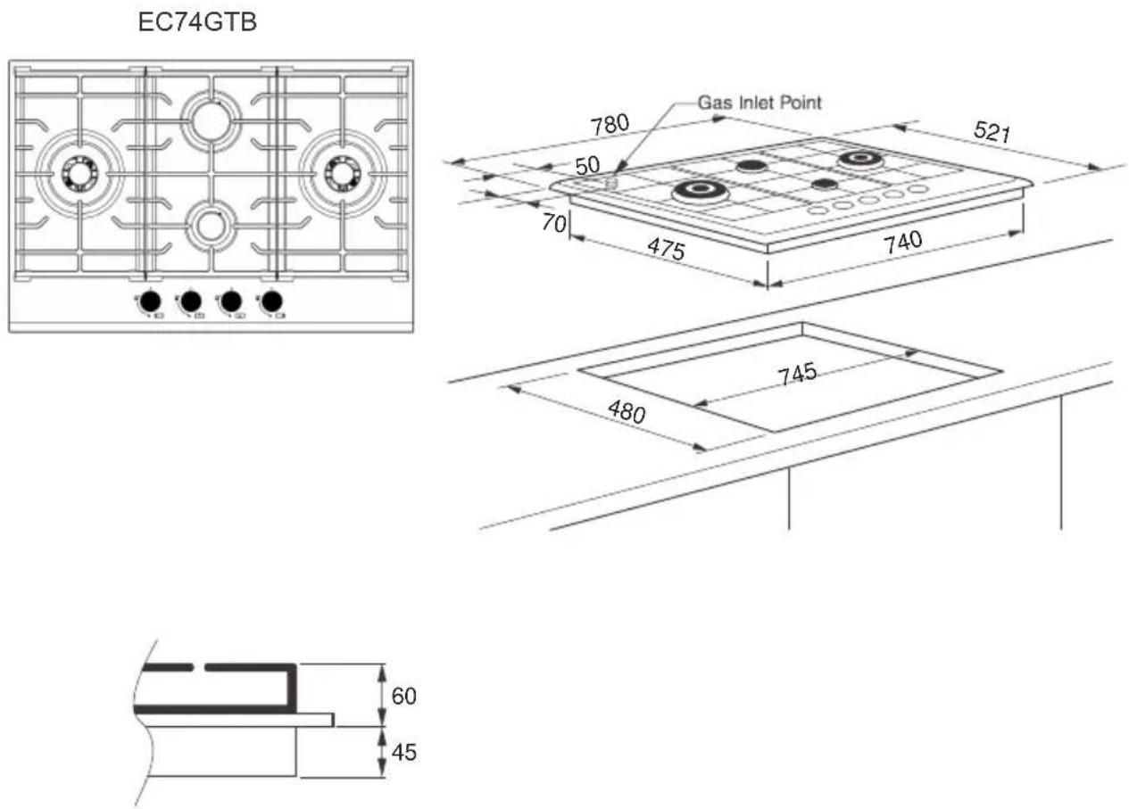
Installation
Installation Cutout Drawings
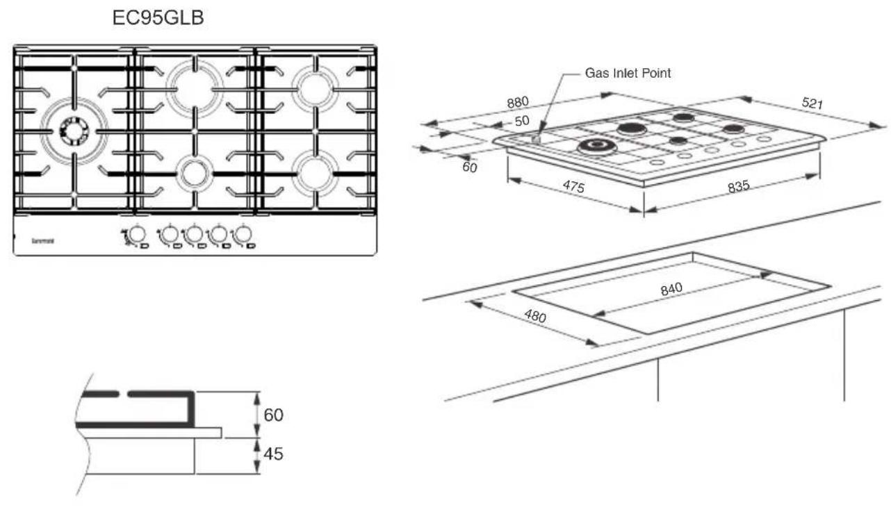
EC95GLS
natural_image
Technical line drawing of a double boiler with cooling fans and rotary switches (no text or symbols)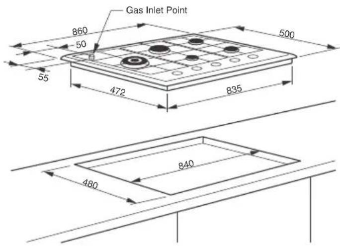
Installation
Connection to the gas supply
There are two ways to make the connection to the main gas line:
A. The hotplate can be connected with rigid pipe as specified in AS/NZS 5601 table 3.1.
B. The hotplate can be connected with a Flexible Hose, which complies with AS/NZS 1869 (Australian Approved), 10mm ID, class B or D, no more than 1.2m long and in accordance with AS/NZS 5601.

WARNING: Ensure that the hose assembly is restrained from accidental contact with the flue or flue outlet of an underbench oven and it does not contact the hot surfaces of the hotplate, oven, dishwasher or other separate appliance that may be installed underneath or next to the hotplate. The hose should not be subjected to abrasion, kinking or permanent deformation and should be able to be inspected along its entire length. Unions compatible with the hose fittings must be used and connections tested for gas leaks.
The supply connection point must be accessible with the appliance installed. Fit the supplied elbow and gasket as shown in the illustration to the right. The gas inlet connection has a 1/2" BSP male thread. When making the connection, take care not to apply excessive stress by counterbalancing tightening force. Ensure that the available gas supply is the same as the gas type label affixed to the base of the hob. If not, contact Glen Dimplex for a Gas Conversion Kit. The gas supply pressure must be adjusted in accordance with the data label for the gas type. Set the minimum level for each burner as described on pages 23 & 24.
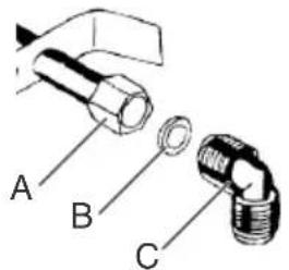
A - Manifold Nut
B - Gasket
C - Elbow
Natural Gas
The natural gas regulator supplied must be fitted for natural gas. Ensure the arrow on the regulator points towards the direction of the gas flow. The test point pressure must be adjusted to 1.00 kPa with the largest burner operating on maximum flame.
ULPG
Fit the ULPG test point assembly (supplied in the gas conversion kit). An Australian Approved gas regulator suitable for a supply pressure of 2.75kPa should be part of the gas tank supply.
Installation
Electrical connection
This appliance is designed to operate on a power supply voltage of 220-240V, single phase and is fitted with a 10A, 3 pin plug. Before making the connection, make sure that:
1) The electrical system is able to withstand the load of the appliance (see data label).
2) The power supply system has an earth connection in good working order in accordance with the regulations in force.
3) The general purpose outlet is easily accessible with the appliance installed.
In all cases, the power supply lead must be positioned so that it does not reach a temperature 50^ C above the room temperature. An ideal route is shown in the 'Correct Installation' below. The cable is guided by cable clips fixed to the side of the cabinet, in order to avoid any contact with any appliance underneath the hob.
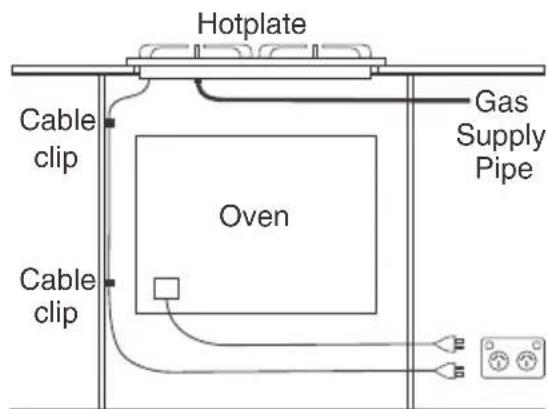

Correct Installation
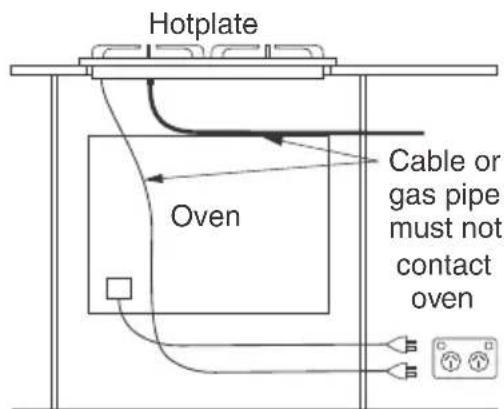

Incorrect
Installation
Replacing the power supply lead
If the supply cord is damaged, it must be replaced by the manufacturer or its service agent or a similarly qualified person in order to avoid hazard.
Installation
Before leaving
When the installation is complete, always check for gas leaks using a soapy solution. Never use a flame to make this check.
Ignite all burners on high flame to ensure correct operation of gas valves, burners and ignition. Turn gas taps to low flame position and observe each burner to ensure they ignite completely at all ports and that the flame is stable. Conduct these checks for each burner individually and concurrently.
When satisfied with the hotplate, please instruct the user on the correct method of operation. In case the appliance fails to operate correctly after all checks have been carried out, please call the Glen Dimplex Service Centre.
Installation
Wiring diagrams
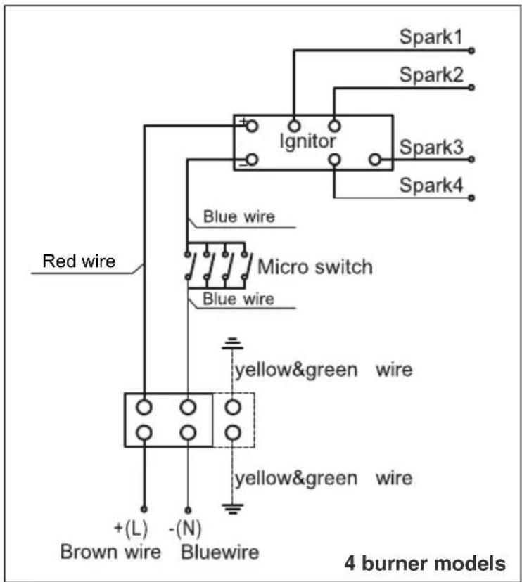
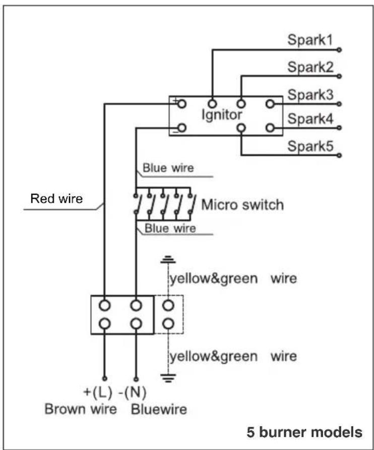
Gas Conversion (NG to ULPG)
If the required gas conversion kit is not supplied with your appliance, contact Glen Dimplex. Gas Conversion shall only be undertaken by authorised persons.
The NG to U-LPG conversion kit contains...
- Test Point Assembly - U
LPG Gas Type label
- Auxiliary Jet ∅0.53mm
- Semi-Rapid Jet ∅0.70mm
- Rapid Jet ∅0.90mm
- 5kw Dual Wok Jet 0.90mm, 0.46mm
- 4kW Wok Jet ∅1.00mm
Converting to a different gas type
When converting from Natural Gas to ULPG ensure that the NG regulator is removed and replaced with the Test Point Assembly supplied in this kit. An Australian Approved gas regulator suitable for a supply pressure of 2.75kPa should be part of the gas tank supply and the test point pressure must be adjusted to 2.75kPa.
Changing the jets
-
Remove pan supports, burner heads and caps.
-
Use a size 7 socket wrench to unscrew and remove the jets, replacing them with those supplied in this kit. Ensure you use the correct jet for the corresponding burner.
-
Reassemble the burner heads, caps and pan supports.
-
Fit the Gas type label supplied with this kit next to the gas connection point and remove the existing label.
Setting the minimum level
-
Light one of the burners and turn the tap to minimum flame.
-
Remove the corresponding control knob.
-
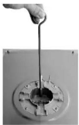
Use a thin blade screwdriver to turn the by-pass screw as shown right.
Turn the by-pass screw fully clockwise. The result should be a small, stable flame which is uniform around the entire burner ring. If not, turn the by-pass screw anti-clockwise until satisfied with the flame.
-
Check that the burner does not go out when the tap is turned quickly from the maximum to the minimum position.
-
Repeat for each burner.
natural_image
Hand pouring liquid into a circular mechanical component (no text or symbols visible)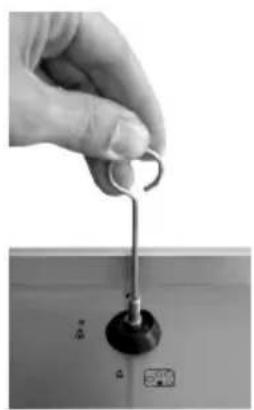
natural_image
Close-up of a hand holding a metal hook attached to a control panel (no visible text or symbols)Gas Conversion (ULPG to NG)
If the required gas conversion kit is not supplied with your appliance, contact Glen Dimplex. Gas Conversion shall only be undertaken by authorised persons.
The ULPG to NG conversion kit contains...
- NG Regulator - NG Gas Type label
- Auxiliary Jet ∅090mm - Semi-Rapid Jet ∅1.18mm
- Rapid Jet ∅1.55mm - 5kw Wok Jet 1.80mm, 0.80mm
- 4kW Wok Jet ∅1.70mm
Converting to a different gas type
When converting from ULPG to Natural Gas ensure that the ULPG test point is removed and replaced with the Australian Approved NG Regulator supplied in this kit. The test point pressure must be adjusted to 1.00kPa with the largest burner operating on maximum flame.
Changing the jets
- Remove pan supports, burner heads and caps.
- Use a size 7 socket wrench to unscrew and remove the jets, replacing them with those supplied in this kit. Ensure you use the correct jet for the corresponding burner.
- Reassemble the burner heads, caps and pan supports.
- Fit the Gas type label supplied with this kit next to the gas connection point and remove the existing label.
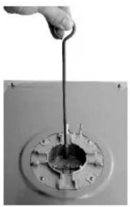
Setting the minimum level
- Light one of the burners and turn the tap to minimum flame.
- Remove the corresponding control knob.
-
Use a thin blade screwdriver to turn the by-pass screw located in the brass shaft as shown right. Turn the by-pass screw fully clockwise then turn it anti-clockwise to achieve the correct flame. The result should be a small, stable flame which is uniform around the entire burner ring. If not, turn the by-pass screw anti-clockwise until satisfied with the flame.
-
Check that the burner does not go out when the tap is turned quickly from the maximum to the minimum position.
-
Repeat for each burner.
natural_image
Hand holding a tool inserted into a circular mechanical component (no visible text or symbols)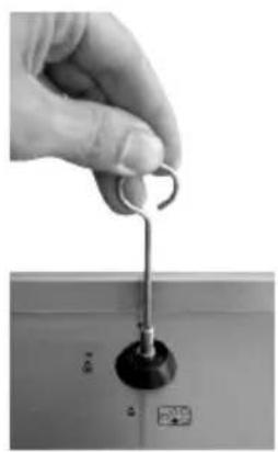
natural_image
Hand holding a metal hook attached to a control panel (no visible text or symbols)Installation
Troubleshooting
Please complete the troubleshooting before calling for service as user error or installation faults WILL NOT be covered under warranty.
General troubleshooting
For all issues with the burners, please check the following items first:
- DO NOT cover any part of the cooktop with foil. As well as being very dangerous, this can cause issues with burners not igniting or burning incorrectly.
- Make sure all parts of the burner referred to on page 7 are clean and dry. Food particles or built up grime can block the flow of gas.
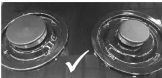
- Check the burner heads and caps are positioned correctly. Compare each burner to the other burners. Check that the caps are on the correct burner head and are sitting flat and even.
natural_image
Close-up of two circular mechanical components with a white checkmark indicating a detail (no text or symbols visible)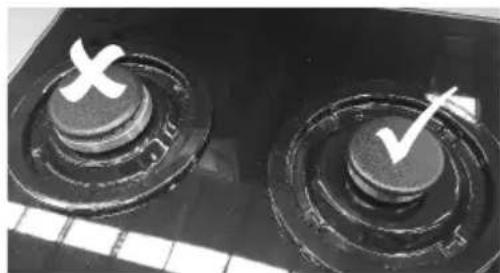
natural_image
Close-up of two circular mechanical components with a white X and checkmark marks, no visible text or symbols.Both caps positioned correctly The cap on the left is from the wrong burner head
OTHER IMPORTANT WARNINGS:
DO NOT leave cooking unattended. Fats or oils may catch fire if overheated. Boil overs may cause damage to the cooktop if not contained immediately.
Using pans which are too large for a particular burner may cause higher temperatures on other surfaces such as control knobs. Please see the sizing guide for pans on page 11.
Installation
Cooktop issues
Burner clicks but will not light:
Complete the general troubleshooting on page 25 first.
When lighting the burner, be sure to turn the knob to the high flame symbol at the 9 o'clock position (see instructions on page 7)
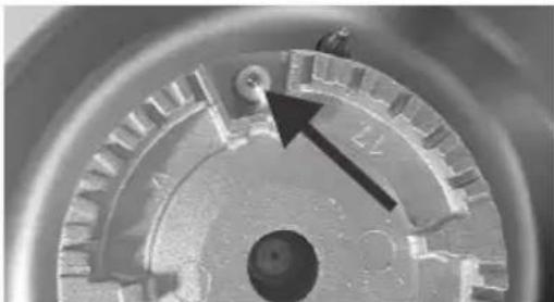
Remove the burner cap. Push the knob (do not turn). When you here the clicking of the ignition, you should be able to see a spark from the ignition candle to the burner head. If you cannot see a spark, call for a service.
natural_image
Close-up of a mechanical gear or cam mechanism with a black arrow pointing to a specific component (no visible text or symbols)Burner does not click when trying to light:
All burners – Check the power supply. The cooktop should be plugged into a power point in the cupboard.
Not all burners – Call for service
Burner won't stay lit:
Complete the general troubleshooting on page 25 first.
Be sure to hold the knob down for at least 5 seconds after the burner lights. This will ensure the flame failure safeguard (thermocouple) has enough time to heat up.
Uneven flame on burner:
Complete the general troubleshooting on page 25 first.
For new installations, be sure cooktop is adjusted for the correct type of gas you are using (Natural gas or ULPG). Your installer should check for correct operation and flame adjustment before leaving.
The flame goes out when turning the burner to the low position:
Complete the general troubleshooting on page 25 first.
For new installations, be sure cooktop is adjusted for the correct type of gas you are using (Natural gas or ULPG). Your installer should check for correct operation and flame adjustment before leaving.
Installation
Cooktop issues (continued)
Ignitor keeps clicking:
It is most likely some moisture has entered the ignition switches under the knobs. This may be from spillage or when cleaning with liquids. Turn off the cooktop at the power point and allow 24-48 hours for it to dry out before switching it back on.
Note: Water will dry out. Oil will take much longer or may not dry out at all.
All burners spark when trying to light one:
This is normal. The ignition for all the burners is linked. A burner will only light when you turn the knob, providing it with gas.
If required, please call the Glen Dimplex service department on 1300 556 816 (AU) or 09 274 8265 (NZ)
MANUFACTURER GUARANTEE
This warranty is provided in Australia by Glen Dimplex Australia Pty Limited ABN 69 118 275 460 (Phone number 1300 556 816) and in New Zealand by Glen Dimplex New Zealand Limited NZBN 9429000069823 (Phone number 09 274 8265) in respect of the Euromaid product.
1. Euromaid Express Warranty
Subject to the exclusions below, we warrant that the product will not have any electrical or mechanical breakdowns within:
a) In the case of Euromaid products used for personal, domestic or household purposes, a period of 2 years from the date the product is purchased as a brand-new product from a retailer located in Australia / New Zealand.
b) In the case of Euromaid products used for purposes other than personal, domestic or household purposes (including business or commercial use), a period of 90 days from the date the product is purchased as a brand-new product from a retailer located in Australia / New Zealand. Euromaid products are designed and intended for domestic use only; and
c) All warranty repairs must be carried out by Glen Dimplex or their nominated service agent
Note: warranty periods detailed above may vary in line with agreements with select retail and builder partners and may differ between Australia and New Zealand.
The benefits conferred by this express warranty are in addition to the Consumer Guarantees referred to in section 3 and any other statutory rights you may have under the Australian / New Zealand Consumer Law and/or other applicable laws.
2. Warranty exclusions
This express warranty does not apply where:
a) The product has been installed, used or operated otherwise than in accordance with the product manual or other similar documentation provided to you with the product;
b) The product requires repairs due to damage resulting from accident, misuse, incorrect installation, insect or vermin infestation, improper liquid spillage, cleaning or maintenance, unauthorised modification, use on an incorrect voltage, power surges and dips, voltage supply problems, tampering or unauthorised repairs by any persons, use of defective or incompatible accessories or exposure to abnormally corrosive conditions, events independent of human control which occurred after the goods left the control of Glen Dimplex;
c) The repair relates to the replacement of consumable parts such as fuses and bulbs or any other parts of the product which require routine replacement;
d) You are unable to provide us with reasonable proof of purchase for the product;
e) the breakdown occurs after the expiry of the express warranty period set out in section 1 or
f) the product was not purchased in Australia / New Zealand as a brand-new product.
3. Consumer guarantees
Our goods come with guarantees that cannot be excluded under the Australian / New Zealand Consumer Law. You are entitled to a replacement or refund for a major failure and for compensation for any other reasonably foreseeable loss or damage. You are also entitled to have the goods repaired or replaced if the goods fail to be of acceptable quality and the failure does not amount to a major failure.
4. How to make a claim
You may make a claim under this warranty through our website, contacting our customer care line or via email. Contact details for Glen Dimplex Australia and New Zealand can be found at the end of this document
To make a valid claim under this warranty, you must:
a) Lodge the claim with us as soon as possible and no later than 14 days after you first become aware of the breakdown;
b) Provide us with the product serial number;
c) Provide us with reasonable proof of purchase for the product. This can take the form of a store receipt, new home handover form or other payment receipt documentation; and
d) If required by us, provide us (or any person nominated by us) with access to the premises at which the product is located at times nominated by us (so that we can inspect the product).
5. Warranty claims
If you make a valid claim under this warranty and none of the exclusions set out in section 2 apply, we will, at our election, either repair the product or replace the product with a product of identical specification (or where the product is superseded or no longer in stock, with a product of as close a specification as possible).
Goods presented for repair may be replaced by refurbished goods of the same type rather than being repaired. Refurbished parts may be used to repair the goods.
Products are designed and supplied for normal domestic use. We will not be liable to you under this warranty for business loss or damage of any kind whatsoever.
Glen Dimplex Australia Pty Ltd Glen Dimplex New Zealand Ltd
www.glendimplex.com.au
www.glendimplex.co.nz
Australia
New
Zealand
Ph: 1300 556 816 Ph: 09 274 8265
customer.care.ha@glendimplex.com.au nztechserv@glendimplex.co.nz
NOTES
READ THE INSTRUCTION BOOKLET BEFORE INSTALLING AND USING THE APPLIANCE.
The manufacturer will not be responsible for any damage to property or to persons caused by incorrect installation or improper use of the appliance.
The manufacturer is not responsible for any inaccuracies, due to printing or transcription errors, contained in this manual. In addition, the appearance of the figures reported is also purely indicative.
The manufacturer reserves the right to make changes to its products when considered necessary and useful, without affecting the essential safety and operating characteristics.
Glen Dimplex constantly seeks ways to improve the specifications and designs of their products. Whilst every effort is made to produce up to date literature, this document should not be regarded as an infallible guide. Actual product only should be used to derive cut out sizes.
All appliances must be installed by a qualified person/s with adherence to the relevant electrical, plumbing and building codes, with compliance being issued as required by state or national legislation.
Additionally, all upright cookers must have the anti-tilt device installed correctly in adherence to the relevant standards by a licenced installer.
For maximum effectiveness and efficiency all rangehoods should be installed with the use of ductwork, by a licenced installer with adherence to the relevant state and national building codes and regulations.
All Glen Dimplex appliances are for Domestic use only, and must be installed by a licence installer into Domestic Applications only, without exception and to the required Authorities guidelines. Any installation outside of this will VOID warranty. Alfresco areas are not a Domestic application.
Euromaid
Distributed by:
Glen Dimplex New Zealand Ltd Glen Dimplex Australia F
www.glendimplex.com.au
www.glendimplex.co.nz
For service advice, please contact the Customer Care Centre by phone or email below.
Australia New Zealand
Ph: 1300 556 816 Ph: 09 274 8265
customer.care.ha@glendimplex.com.au nztechserv@glendimplex.co.nz
- Contents
- For your safety
- Use and Care
- Installation
- DURING USE
- During use (continued)
- Safety of children and the infirm
- Cleaning and maintenance
- Service and repairs
- Environmental protection advice
- Instructions for use
- Regular burners (Auxiliary, Semi Rapid, Rapid, Wok)
- Dual Valve Wok burner (Not all models)
- All burners
- To light the burners
- Using the Dual Valve Wok burner (not all models)
- For correct use of the hob
- General cleaning
- Stainless steel hob
- Glass hob
- Ignition plug
- Routine maintenance
- Abnormal operation
- Service and parts
- Warranty
- Technical data
- Instructions for installation
- Building into kitchen benches
- Insertion and fixing
- Combustible Surfaces as per AS/NZS 5601
- Connection to the gas supply
- Natural Gas
- ULPG
- Electrical connection
- Replacing the power supply lead
- Before leaving
- Gas Conversion (NG to ULPG)
- The NG to U-LPG conversion kit contains...
- Converting to a different gas type
- Changing the jets
- Setting the minimum level
- Gas Conversion (ULPG to NG)
- Troubleshooting
- General troubleshooting
- OTHER IMPORTANT WARNINGS:
- Cooktop issues
- Burner clicks but will not light:
- Burner does not click when trying to light:
- Burner won't stay lit:
- Uneven flame on burner:
- The flame goes out when turning the burner to the low position:
- Ignitor keeps clicking:
- All burners spark when trying to light one:
- MANUFACTURER GUARANTEE
- Euromaid Express Warranty
- Warranty exclusions
- Consumer guarantees
- How to make a claim
- Warranty claims
- Glen Dimplex Australia Pty Ltd Glen Dimplex New Zealand Ltd
- NOTES
- READ THE INSTRUCTION BOOKLET BEFORE INSTALLING AND USING THE APPLIANCE.
- Euromaid
Brand : Euromaid
Model : EC74GTB
Category : Cooker