
AOD-210 - Motion detector Satel - Free user manual and instructions
Find the device manual for free AOD-210 Satel in PDF.


| Product Type | Wireless outdoor dual technology motion detector |
| Brand | Satel |
| Model | AOD-210 |
| Detection Technology | Passive infrared (PIR) and microwave (MW) |
| Frequency Band | 868.0 MHz – 868.6 MHz / 915 MHz – 928 MHz |
| Communication | Encrypted two-way radio (AES standard for ABAX 2), ABAX 2 / ABAX compatible |
| Coverage Area | 16 m x 16 m, 90° detection angle |
| Detectable Speed | 0.3 m/s to 3 m/s |
| Pet Immunity | Up to 20 kg |
| Recommended Installation Height | 2.4 m |
| Operating Temperature | -40°C to +55°C |
| Maximum Humidity | 93±3% |
| IP Code | IP54 |
| Dimensions (H x W x D) | 65 x 138 x 58 mm |
| Weight | 182 g |
| Power Supply | CR123A 3V lithium battery |
| Battery Life | Up to 2 years (up to 4 years with ECO mode enabled) |
| Standby Current Consumption | 75 μA |
| Maximum Current Consumption | 30 mA |
| Compliance | EN 50131-1, EN 50130-4, EN 50130-5, Grade 2 (EN 50131-2-4) |
| Additional Features | Digital temperature compensation, dusk sensor, tamper protection, 3 LED indicators, remote firmware update (ABAX 2 only), ECO mode |
| Maintenance | Clean enclosure with a damp cloth; do not use solvents. Replace battery when low. |
| Reparability | Only qualified personnel should repair; no user-serviceable parts except battery. |
Frequently Asked Questions - AOD-210 Satel
User questions about AOD-210 Satel
0 question about this device. Answer the ones you know or ask your own.
Ask a new question about this device
Download the instructions for your Motion detector in PDF format for free! Find your manual AOD-210 - Satel and take your electronic device back in hand. On this page are published all the documents necessary for the use of your device. AOD-210 by Satel.
USER MANUAL AOD-210 Satel
Wireless outdoor dual technology motion detector
CE
Firmware version 1.01 aod-210_en 03/21
IMPORTANT
The device should be installed by qualified personnel.
Prior to installation, please read carefully this manual.
Changes, modifications or repairs not authorized by the manufacturer shall void your rights under the warranty.
Rating plate of the device can be found on the rear side of the electronics module.
SATEL aims to continually improve the quality of its products, which may result in changes in their technical specifications and software. Current information about the changes being introduced is available on our website.
Please visit us at: https://support.satel.eu
Hereby, SATEL sp. z o.o. declares that the radio equipment type AOD-210 is in compliance with Directive 2014/53/EU. The full text of the EU declaration of conformity is available at the following internet address: www.satel.eu/ce
In the EU, this radio equipment is only permitted to operate in the 868 MHz frequency band.
The following symbols may be used in this manual:

- note,

- caution.
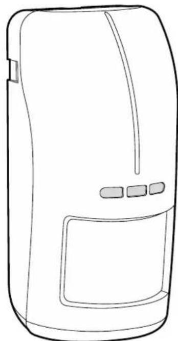
The AOD-210 outdoor detector detects movement in a protected area. It is designed for operation within the ABAX 2 / ABAX two-way wireless system. This manual applies to the detector with firmware version 1.01, which is supported by:
- ABAX 2:
- ACU-220 / ACU-280 controller,
- ARU-200 repeater.
- ABAX:
- ACU-120 / ACU-270 controller (firmware version 5.04 or newer),
- ARU-100 repeater (firmware version 2.02 or newer),
- INTEGRA 128-WRL control panel (firmware version 1.19 or newer and firmware version of processor used to operate ABAX system 3.10 or newer).
1 Features
- Motion detection with two sensors: passive infrared sensor (PIR) and microwave sensor (MW).
- Adjustable detection sensitivity of both sensors.
- Digital motion detection algorithm for both sensors.
• Digital temperature compensation. - Pet immunity up to 20 kg.
- Immunity to false alarms caused by moving but not changing their position objects (e.g. branches of trees).
- Creep zone.
- Dusk sensor.
- Encrypted two-way radio communication in the 868 MHz / 915 MHz frequency band (AES standard for the ABAX 2 system).
- Transmission channel diversity – 4 channels for automatic selection of the one that will enable transmission without interference with other signals in the 868 MHz / 915 MHz frequency band (ABAX 2 system only).
- Remote update of detector firmware (ABAX 2 system only).
- Remote configuration.
• Built-in temperature sensor (temperature measurement range from -40°C to +55°C ). - Three LED indicators.
• Supervision of motion detection system. - "ECO" option for longer battery life (ABAX 2 system only).
- Battery status control.
- Tamper protection against enclosure opening and removal from mounting surface.
- Weatherproof enclosure featuring a very high mechanical strength.
2 Description
The detector occupies two positions on the device list:
• the first one: motion detector,
• the other one: dusk detector.
Optionally the detector can occupy one position – only the motion detector is supported.
Radio communication
The detector connects to the controller / control panel at regular time intervals to provide information about its state (periodical communication). Additional communication may take place as a result of alarm (see “Operating modes”).
Alarms
The detector will report alarm:
- after detecting a motion in the protected area by both sensors within a time period shorter than 4 seconds (this alarm can only be reported in the active mode – see “Operating modes”),
• after detecting a fault in the motion detection system, - when the light intensity drops below a defined threshold,
• after opening the tamper switch (tamper alarm).
Operating modes
Active – information about tamper alarm, motion detection alarm and light intensity drop alarm is sent immediately. The microwave sensor is enabled after motion is detected by the infrared sensor.
Passive – only information about tamper alarm and light intensity drop alarm is sent immediately. The microwave sensor is disabled, therefore no alarm can be triggered after motion is detected. During periodical communication, information on whether the PIR sensor detects motion is sent. This operating mode prolongs the battery life.
The detector operating mode is turned on remotely. If the detector is used in the INTEGRA / VERSA alarm system, the operating mode may depend on the partition state (partition disarmed – passive mode; partition armed – active mode). For more information, refer to the ABAX 2 / ABAX controller manual / the INTEGRA 128-WRL control panel manual.
Energy saving mode (ECO)
If you want to prolong the battery life, you can enable in the detector the “ECO” option. When the “ECO” option is enabled, the periodical communication takes place every 3 minutes. Thus the battery life can be increased as much as fourfold. The option is only available in the ABAX 2 system. The detector with “ECO” option enabled meets requirements of the EN 50131-2-4 standard for Grade 2.
Dusk sensor
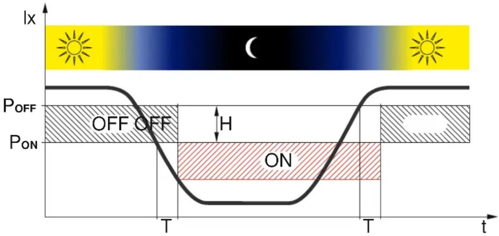
Figure 1 shows the way the dusk sensor operates. On the timeline the T time delay is presented (in operating mode T=3 min, in configuring mode T=3 s). Illustrated with the letter H light intensity hysteresis and time delay make the sensor immune to short and accidental changes of light intensity. Table 1 presents light intensity values for four detection thresholds. For description of how to configure the sensor, please refer to the ABAX 2 / ABAX controller manual / the INTEGRA 128-WRL control panel manual.
Information about the light intensity drop below the defined threshold (alarm) and the light intensity restoration above the threshold (alarm restore) is sent instantly (regardless of the operating mode).
1
| Light intensity | ||
| Detection threshold | Turning on [PON] | Turning off [POFF] |
| 1 | 5 lx | 10 lx |
| 2 | 10 lx | 20 lx |
| 3 | 30 lx | 50 lx |
| 4 | 40 lx | 70 lx |
Table 1
Test mode
The test mode makes the detector testing easier, because the LED indicators are enabled and the dusk sensor reacts quicker to changes in the light intensity. How to start and end the test mode is described in the ABAX 2 / ABAX controller manual / the INTEGRA 128-WRL control panel manual.

After starting the test mode, automatic calibration of the microwave sensor is carried out. For 10 seconds after the test mode is started, there should be no moving object in the detection area of the microwave sensor, as this will prevent proper calibration of the sensor.
LEDs
The LEDs are flashing for about 40 seconds from inserting the battery, thus signaling the warm-up of the detector. The LEDs also work in the test mode, in which they indicate:
- periodical communication – short flash of the red LED (80 milliseconds).
- motion detection by the microwave sensor – the green LED is ON for 4 seconds.
- motion detection by the PIR sensor – the yellow LED is ON for 4 seconds.
- alarm – the red LED is ON for 2 seconds.
Supervision of motion detection system
When the motion detection system starts malfunctioning, the detector will report an alarm during periodical communication. The alarm will keep going until the fault is cleared (long violation).
Battery status control
When the battery voltage is below 2.75 V, information about low battery is sent during each transmission.

In response to the battery voltage drop below 2.75 V, sensitivity of sensors in the detector is automatically lowered to eliminate false alarms.
When replacing the battery, wait about 1 minute between removing the old battery and installing the new one.
Electronics module

Do not remove the plastic cover from the circuit board to prevent damage to the components located on the board.
Do not touch the pyroelectric sensor, so as not to soil it.
① TMP terminals – tamper input (NC).
② pins to enable/disable the tamper input. If no additional tamper switch is connected to the TMP terminals, jumper should be placed across the pins.
③ CR123A lithium battery.
④ microwave sensor.
⑤ green LED.
⑥ red LED.
⑦ yellow LED.
⑧ dusk sensor.
⑨ PIR sensor (dual element pyrosensor).
⑩ tamper switch activated by cover removal.
⑪ fixing screw holes.
On the other side of the electronic board is a tamper switch activated by removing the detector from the wall.


When mounting the detector on the angle or ball bracket, it is recommended to install additional tamper switch.
3 Selecting a mounting location
• Install the detector at the recommended height (Fig. 3-I).
- If traffic nearby or objects moving out of the protected area cause an alarm, move the detector slightly downwards or reduce the detector sensitivity (Fig. 3-II).
- Install the detector so that the expected movement of an intruder will be across the coverage pattern (Fig. 3-III).
- Don't install the detector closer than 3 meters from the moving objects (e.g. tree branches, bushes, laundry etc.) (Fig. 3-IV).
- Don't direct the detector on reflective surfaces or on fans or a heat sources (Fig. 3-V).
3


4 Installation

There is a danger of battery explosion when using a different battery than recommended by the manufacturer, or handling the battery improperly.
Be particularly careful during installation and replacement of the battery. The manufacturer is not liable for the consequences of incorrect installation of the battery.
The used batteries must not be discarded, but should be disposed of in accordance with the existing rules for environment protection.
If the detector is to be immune to the motion of pets, it should be mounted at a height of 2.4 m without any vertical deflection. It must be borne in mind, especially in the case of ball-type bracket mounting.
- Remove the front cover (Fig. 4).
- Install the battery and secure it with the clip you will find in the package.
- Add the detector to the wireless system (see the ABAX 2 / ABAX controller manual or the INTEGRA 128-WRL control panel installer manual). The sticker with serial number which shall be entered when registering the detector in the system can be found on the electronics module.

In the INTEGRA / VERSA alarm system, the detector is identified as AOD-200.
Simultaneous operation of the detector by the ABAX 2 and ABAX controller / INTEGRA 128-WRL alarm control panel is not possible.



- Replace the cover.
- Put the detector at the place of its future installation.
- Check the level of signal received from the detector by the ABAX 2 / ABAX controller or the INTEGRA 128-WRL control panel. If the signal level is lower than 40% , select another place for installation. Sometimes, it is sufficient to shift the device ten or twenty centimeters to obtain a considerable improvement in the signal quality.
i
The ARF-200 tester makes it possible to check the radio signal strength at the place of future installation without having to put the detector there.
- Remove the front cover (Fig. 4).
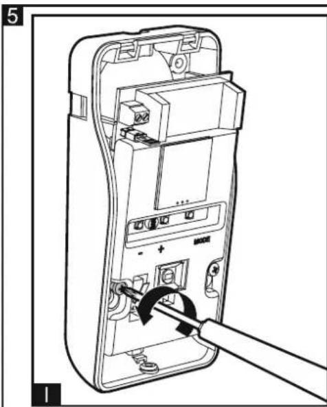
- Remove the electronics module (Fig. 5).
- If the detector is to be mounted on angle bracket or ball bracket, make a hole in the enclosure base for the additional tamper switch cables.
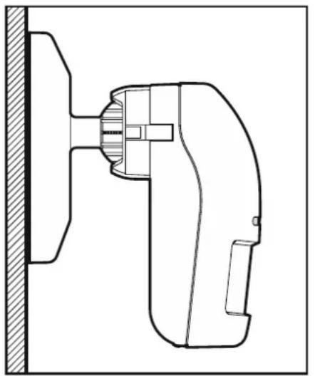
- Mount the enclosure base to the wall, to the angle bracket (see: "Angle bracket mounting") or to the ball bracket (see: "Ball bracket mounting"). The wall plugs (anchors) delivered with the device are intended for concrete, brick, etc. For other types of surface (drywall, styrofoam), use the appropriately selected wall plugs. In Figure 6 possible ways of mounting the detector are shown.
6

- Fasten the electronics module in the enclosure.
- If you have mounted the detector on a bracket, connect an additional tamper switch to the TMP terminals (black wire to one terminal, blue wire to the other) and remove the jumper from the pins.
- Replace the cover.
- Configure the detector settings (sensitivity of PIR sensor, sensitivity of microwave sensor, sensitivity of dusk sensor [detection threshold], etc. – see the ABAX 2 / ABAX controller manual / the INTEGRA 128-WRL control panel manual).
i
If the detector is to be pet immune, for the infrared and microwave sensors do not set the detection sensitivity higher than default (PIR sensor sensitivity: 2, MW sensor sensitivity: 1).
-
Start the test mode (see the ABAX 2 / ABAX controller manual / the INTEGRA 128-WRL control panel manual).
-
Check whether moving around within the detector coverage area will get the LEDs to come on. Fig. 9 shows the maximum detection range and the creep zone.
-
End the test mode.
4.1 Angle bracket mounting
-
Attach extra tamper switch:
-
screw the holder to the tamper switch (Fig. 7-I),
- screw the tamper unit to the enclosure base (Fig. 7-III).
i
Figure 7 shows mounting the tamper switch in one of two available positions. The place of tamper switch installing depends on the way of angle bracket mounting. If the tamper switch is to be installed in the other position, place tamper switch holder on the other side.
- Prepare openings in the bracket for screws.
- Using wall plugs and screws, fasten the bracket to the wall.
- Run the tamper switch wires through the hole made in the enclosure base.
i
It is recommended that the tamper switch wires be placed in a heat shrink tubing. This will reduce the risk of water penetration into the enclosure.
- Using screws, fasten the enclosure base to the bracket (Fig. 7-IV).
7


4.2 Ball bracket mounting
-
Attach extra tamper switch:
-
screw the holder to the tamper switch (Fig. 8-I),
- put the unit making the surface bigger on the tamper switch (Fig. 8-II),
-
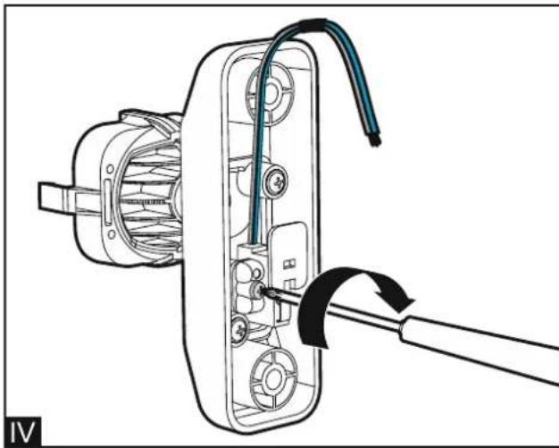
screw the tamper unit to the ball bracket (Fig. 8-IV).
-
Run the cable through the opening in the handle of the bracket.
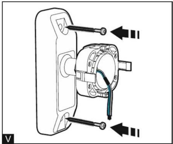
- Using wall plugs and screws, fasten the ball bracket to the wall (Fig. 8-V).
- Run the tamper switch wires through the hole made in the enclosure base.

It is recommended that the tamper switch wires be placed in a heat shrink tubing. This will reduce the risk of water penetration into the enclosure.
- Using screws, fasten the enclosure base to the ball bracket (Fig. 8-VII).
8




9


5 Specifications
Operating frequency band....868.0 MHz ÷ 868.6 MHz / 915 MHz – 928 MHz Radio communication range (in open area)
ABAX 2
ACU-220 up to 2000 m
ACU-280 up to 1600 m
ABAX up to 500 m
Battery CR123A 3 V
Battery life expectancy up to 2 years
Temperature measurement range ....-40°C...+55°C
Temperature measurement accuracy ....±1°C
Standby current consumption 75 μA
Maximum current consumption....30 mA
Microwave frequency 24.125 GHz
Detectable speed 0.3...3 m/s
Warm-up period 40 s
Recommended installation height 2.4 m
Coverage area 16 m x 16 m, 90°
Complied with standards....EN 50131-1, EN 50130-4, EN 50130-5
Security grade according to EN 50131-2-4 ...... Grade 2
Environmental class according to EN 50130-5 ....... Illa
Operating temperature range....-40°C...+55°C
Maximum humidity....93±3%
IP code....IP54
Dimensions....65 x 138 x 58 mm
Weight....182 g


- WIRELESS OUTDOOR DUAL TECHNOLOGY MOTION DETECTOR
- IMPORTANT
- 1 FEATURES
- 2 DESCRIPTION
- RADIO COMMUNICATION
- ALARMS
- OPERATING MODES
- ENERGY SAVING MODE (ECO)
- DUSK SENSOR
- TEST MODE
- LEDS
- SUPERVISION OF MOTION DETECTION SYSTEM
- BATTERY STATUS CONTROL
- ELECTRONICS MODULE
- 3 SELECTING A MOUNTING LOCATION
- 4 INSTALLATION
- I
- 4.1 ANGLE BRACKET MOUNTING
- 4.2 BALL BRACKET MOUNTING
- 5 SPECIFICATIONS
Brand : Satel
Model : AOD-210
Category : Motion detector