A-145 - Synthesizer Doepfer - Free user manual and instructions
Find the device manual for free A-145 Doepfer in PDF.


| Product Type | Synthesizer Module (LFO) |
| Brand | Doepfer |
| Model | A-145 |
| Category | Eurorack Module |
| Functions | Low Frequency Oscillator with five waveforms: sawtooth, inverted sawtooth, triangle, sine, square |
| Frequency Range | Selectable via switch: Low (up to several minutes per cycle), Medium (standard LFO), High (audio range up to ~20 kHz) |
| Controls | Frequency knob, 3-position Range switch (L, M, H) |
| Outputs | Six outputs: inverted sawtooth, sawtooth, sine, triangle, square (all ±2.5V); plus Reset In (trigger input) |
| LED Indicators | Two LEDs: one for sawtooth output frequency, one for sine/triangle output frequency |
| Power Supply | Standard Eurorack +12V / -12V (typical consumption not specified, estimate 20mA each) |
| Width | 8 HP (approx. 40.3 mm) |
| Depth | Approximately 35 mm (standard Doepfer module depth) |
| Mounting | Eurorack compatible |
| Maintenance | No specific maintenance required; keep dry and dust-free |
| Safety | Disconnect power before installation; ensure correct power ribbon orientation |
| Spare Parts / Repairability | Not specified; contact Doepfer or authorized retailers for service |
| Included Accessories | Power ribbon cable, mounting screws (typically) |
| Warranty | Check with retailer; standard Doepfer warranty period applies |
| Manufacturer | Doepfer Musikelektronik GmbH |
Frequently Asked Questions - A-145 Doepfer
User questions about A-145 Doepfer
0 question about this device. Answer the ones you know or ask your own.
Ask a new question about this device
Download the instructions for your Synthesizer in PDF format for free! Find your manual A-145 - Doepfer and take your electronic device back in hand. On this page are published all the documents necessary for the use of your device. A-145 by Doepfer.
USER MANUAL A-145 Doepfer
1. Introduction
Module A-145 (LFO) is a low frequency oscillator, which produces cyclical control voltages in a very wide range of frequencies.
Five waveforms are available: sawtooth, inverted sawtooth, triangle, sine and square wave.
The LFO can be used as a modulation source for any number of modules - for instance modulating the pulse width or frequency of a VCO, modulation of the cut-off frequency of a VCF, or amplitude modulation with a VCA.
A three-way switch lets you select three frequency ranges, spanning from one cycle every several minutes at the lowest, to audio frequency at the highest.
The LFO signal can also be synchronised, via the reset input.
2. Overview
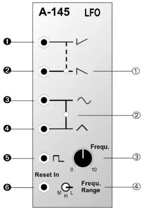
Controls and indicators
① LED: frequency indicator for the sawtooth wave at output ②
② LED: frequency indicator for the sine and square waves at output ③ and/or ④
③ Frequ.: frequency control
④ Frequ. Range: switch for selecting frequency range
In / Outputs
1 : output: inverted sawtooth
② : output: sawtooth
③ : output: sine wave
④ : output: triangle
⑤ : output: square wave
⑥ Reset In: synchronisation input
3. Controls and indicators
① LED ... ② LED
LEDs ① and ② show the frequency of the voltage output at sockets ② to ④.

If the LFO frequency goes above about 15 Hz, our persistence of vision means that the LEDs look permanently on.
③ Frequ.
This control adjusts the frequency of the LFO, within the parameters of the frequency range set by switch ④.
④ Frequ. Range
Use switch ④ to select a suitable frequency range from the three available:
• L (low): up to several minutes per cycle
• M (medium): normal LFO range
• H (high): audio range
4. In / Outputs

This is the output for the inverted sawtooth. (Amplitude: ± 2.5 V).

This is the output for the ordinary sawtooth, whose frequency is displayed by LED ①. (Amplitude: ± 2.5 V).

This is the output for the sine wave, whose frequency is displayed by LED ②. (Amplitude: ±2.5 V.)

This is the output for the triangle wave, whose frequency is displayed by LED ②. (Amplitude: ±2.5 V.)

This is the output for the square wave (Amplitude: ± 2.5 V.)
⑥ Reset In
LFO synchronisation is possible, by sending a trigger signal (eg. a gate) to the reset input. Every time a trigger voltage is sensed (for instance when a key is pressed), the LFO's waveform resets, and starts from its zero point (see Fig. 2).
Without synchronisation, the LFO is free running, so that wherever the waveform is when the trigger arrives, that's where it starts from (see Fig. 1).

Particularly with lower frequency modulations, you can use the reset / synchronisation option to make sure that the LFO starts from zero whenever a key is pressed (Keyboard Gate Reset LFO).
If you don't want this effect, then leave the reset input unconnected, for a random LFO waveform response.
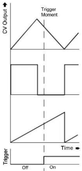
Fig. 1: LFO without Synchronisation
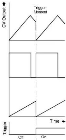
Fig. 2: LFO with Synchronisation
5. User examples
An LFO can be used for all sorts of different modulations:
• LFO - VCA (A-130, A-131, A-132)
Modulation of the gain produces Tremolo
• LFO - VCF (A-120, A-121, A-122, A-123)
Modulation of the cut-off frequency produces cyclical variation in tone colour - Wah-wah
• LFO - VCO (PWM A-110, A-111)
Pulse width modulation using the LFO produces cyclical variation in tone colour (phasing type)
• LFO - VCO (FM A-110, A-111)
Pitch modulation using LFO produces vibrato.
• LFO - VCP (A-125)
Phase shift modulation using LFO produces cyclic phasings or phase vibrato
The above effects occur with LFO frequencies in the sub-audio range. Once the LFO gets into the audio range, timbral changes always occur. Examples and further notes can be found in the manuals for the respective modules.
Producing echo effects
As well as modulation effects, LFOs can also create time-based repeat effects. In Fig. 3 the LFO is being used to produce an echo effect. The frequency and waveform of the LFO determine the delay-time and character of the sound, and the ADSR parameters determine the envelope and feedback amount of the echoes.
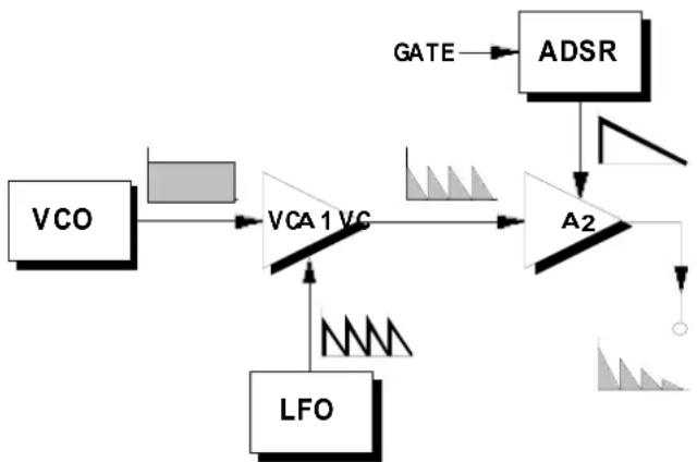
flowchart
graph TD
    A["VCO"] --> B["VCA1VC"]
    C["LFO"] --> B
    B --> D["A2"]
    E["ADSR"] --> D
    D --> F["GATE"]
    B --> G["Waveform Signal"]
Fig. 3: Producing an echo effect
6. Patch-Sheet
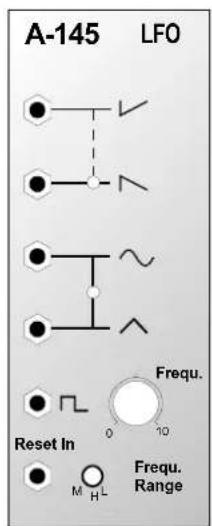
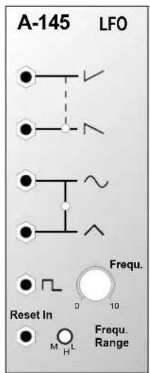
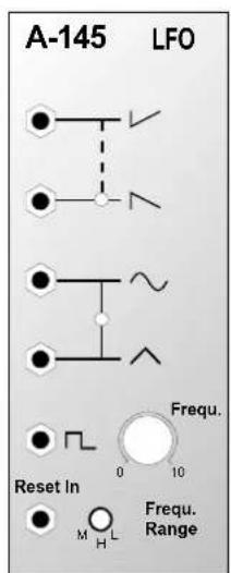
The following diagrams of the module can help you recall your own Patches. They're designed so that a complete 19" rack of modules will fit onto an A4 sheet of paper.
Photocopy this page, and cut out the pictures of this and your other modules. You can then stick them onto another piece of paper, and create a diagram of your own system.
Make multiple copies of your composite diagram, and use them for remembering good patches and set-ups.

- Draw in patchleads with colored pens.
- Draw or write control settings in the little white circles.
Brand : Doepfer
Model : A-145
Category : Synthesizer