AcousticCoverage AC-C4T-nb - Loudspeaker QSC - Free user manual and instructions
Find the device manual for free AcousticCoverage AC-C4T-nb QSC in PDF.


| Product Type | Ceiling loudspeaker |
| Brand | QSC |
| Model | AcousticCoverage AC-C4T-nb |
| Driver Size | 4 inch |
| Dimensions (W x D) | 7.1 x 5.5 inches (cutout 6.2 inches) |
| Weight | 3.5 lbs |
| Power Handling | 30W continuous, 60W peak |
| Impedance | 8 ohms (bypass transformer) |
| Transformer Taps (70V/100V) | 1.5, 3, 6, 12W |
| Frequency Response | 70 Hz - 20 kHz |
| Sensitivity | 88 dB SPL (1W/1m) |
| Coverage Angle | 120° conical |
| Enclosure Material | Steel with paintable grille |
| Installation | Ceiling mount with included tile bridge |
| Compliance | UL 1480, UL 2043 |
| Wiring | 4-pin removable connector |
| Color | White (paintable) |
| Warranty | 6 years |
Frequently Asked Questions - AcousticCoverage AC-C4T-nb QSC
User questions about AcousticCoverage AC-C4T-nb QSC
0 question about this device. Answer the ones you know or ask your own.
Ask a new question about this device
Download the instructions for your Loudspeaker in PDF format for free! Find your manual AcousticCoverage AC-C4T-nb - QSC and take your electronic device back in hand. On this page are published all the documents necessary for the use of your device. AcousticCoverage AC-C4T-nb by QSC.
USER MANUAL AcousticCoverage AC-C4T-nb QSC
AcousticCoverage (AC)
User Manual
Model: AC-C4T-nb & AC-C8T-nb
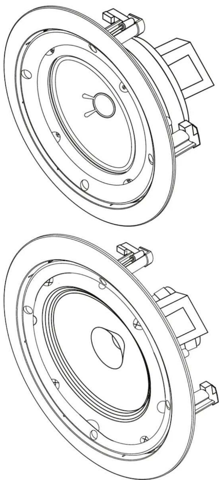
EXPLANATION OF SYMBOLS
The term "WARNING!" indicates instructions regarding personal safety. If the instructions are not followed the result may be bodily injury or death.
The term “CAUTION!” indicates instructions regarding possible damage to physical equipment. If these instructions are not followed, it may result in damage to the equipment that may not be covered under the warranty.
The term "IMPORTANT!" indicates instructions or information that are vital to the successful completion of the procedure.
The term "NOTE" is used to indicate additional useful information.

The intent of the lightning flash with arrowhead symbol in a triangle is to alert the user to the presence of un-insulated “dangerous” voltage within the product’s enclosure that may be of sufficient magnitude to constitute a risk of electric shock to humans.

The intent of the exclamation point within a triangle is to alert the user to the presence of important safety, and operating and maintenance instructions in this manual.

IMPORTANT SAFETY INSTRUCTIONS

- Read these instructions
- Keep these instructions.
- Heed all warnings.
- Follow all instructions.
- Do not use this apparatus near water.
- Clean only with a dry cloth.
- Do not install near any heat sources such as radiators, heat registers, stoves, or other apparatus (including amplifiers) that produce heat.
- Only use attachments/accessories specified by the manufacturer.
- Refer all servicing to qualified service personnel. Servicing is required when the apparatus has been damaged in any way, such as power-supply cord or plug is damaged, liquid has been spilled or objects have fallen into the apparatus, the apparatus has been exposed to rain or moisture, does not operate normally, or has been dropped.
- Do not use this apparatus in or near water or liquids.
- Do not submerge the apparatus in water or liquids.
- Do not use any aerosol spray, cleaner, disinfectant or fumigant on, near or into the apparatus.
- Do not block any ventilation opening. Install in accordance with the manufacturer's instructions.
- Keep ventilation opening free of dust or other matter.
- Adhere to all applicable, local codes.
- Consult a licensed, professional engineer when any doubt or questions arise regarding a physical equipment installation.
Maintenance and Repair
Advance technology, e.g., the use of modern materials and powerful electronics, requires specially adapted maintenance and repair methods. To avoid a danger of subsequent damage to the apparatus, injuries to persons and/or the creation of additional safety hazards, all maintenance or repair work on the apparatus should be performed only by a QSC authorized service station or an authorized QSC International Distributor. QSC is not responsible for any injury, harm or related damages arising from any failure of the customer, owner or user of the apparatus to facilitate those repairs.
Warranty
For a copy of the QSC Limited Warranty, visit the QSC website at www.qsc.com
- Use the template provided to mark and cut a hole in the ceiling where the loudspeaker is to be installed.
Wire the Loudspeakers
Refer to Figure 1.
- On the loudspeaker transformer, identify the common (black) and the appropriate color coded wire for the desired wattage tap.
- Trim the ends of the non used color coded tap wires to ensure no bare ends come into contact with other tap wires or metal surfaces.
- Using wire nuts or crimps, attach the speaker supply wire negative to the common (black) lead of the transformer. Attach the speaker supply wire positive to the selected color coded transformer lead.

WARNING!: Do not attach more than one color coded transformer tap lead. This may result in transformer saturation and possibly damage the loudspeaker.
Mount the Loudspeaker
Refer to Figure 2.
- Make sure all of the dog-ears are fully extended and in their non-capture position.
- Position the loudspeaker into the hole prepared in the ceiling.
- Use a Phillips screwdriver to tighten each of the four dog-ear screws. As you tighten the screws, the dog-ears will swing into capture position over the ceiling. Be sure all dog-ears are properly positioned over the ceiling.
- Tighten the dog-ears until firm contact is made with the ceiling surface.

CAUTION!: Do not overtighten the dog-ear screws!
- Install the loudspeaker grill.
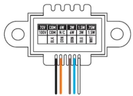
- Figure 1. -
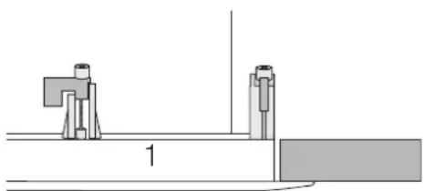
natural_image
Pure mechanical assembly diagram showing two components and a base, without any text, numbers, or symbols.Dog-ears against loudspeaker
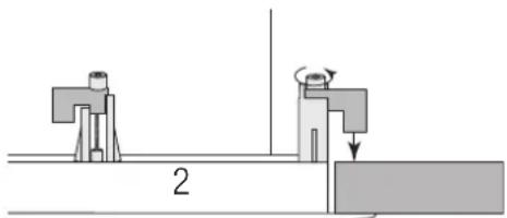
natural_image
Mechanical assembly diagram showing two components with a rotating arrow and label '2' (no text or symbols beyond basic labels)Tum the screw clockwise to engage the dog-ear with the ceiling.
- Figure 2. -
Dimensions
AC-C4T-nb
![3.75 in [95 mm] 6.7 in [170 mm] 8.11 in [206 mm]](/content/2026/05/928451/images/77668022231995604b5e9fa29e28e4a36848ed44fedd3b93cb2fbf811be9f377.jpg)
AC-C8T-nb
![3.3 in [84 mm] 9.6 in [244 mm] 11.14 in [283 mm]](/content/2026/05/928451/images/d9024f0a298a585999563ab6a8fcfdf8f46d770505cafec5364efd6ade55ce0e.jpg)
Specifications
AC-C4T-nb AC-C8T-nb
| Transducer 100 mm [4 in.] weather treated paper cone 200 mm [8 in.] weather treated paper cone | ||
| Rated noise power [rms] (1) | 6 W 6 W | |
| Nominal Impedance | 8Ω8Ω | |
| Transformer Taps 70V: 6, 3, 1.5, 0.75 W | 70V: 6, 3, 1.5, 0.75 W | |
| 100V: 6, 3, 1.5 W | 100V: 6, 3, 1.5 W | |
| Effective frequency range (2) | 62 Hz – 18 kHz 53 Hz – 20 kHz | |
| Rated coverage (3) | 140° conical 130° conical | |
| Directivity factor 4 5.6 | ||
| Directivity index [dB] 6 7.5 | ||
| Sensitivity (4) | 93 dB 96 dB | |
| Maximum continuous SPL (5) | 101 dB 104 dB | |
| Maximum peak SPL (5) | 107 dB 110 dB | |
| Baffle material ABS | ABS | |
| Grille material | Powder coated steel | Powder coated steel |
| Cutout dimension | ∅ 178 mm [∅ 7 in] | ∅ 254 mm [∅ 10 in] |
| Net weight | 1.2 kg [2.6 lb] | 1.5 kg [3.4 lb] |
| Product dimensions (Diameter x Height) | ∅ 206 x 95 mm [∅ 8.11 x 3.75 in.] | ∅ 283 x 84 mm [∅ 11.14 x 3.3 in.] |
| Shipping weight | 5.9 kg [13.1 lb] (packs of 4) | 7.8 kg [17.3 lb] (packs of 4) |
| Shipping dimensions (H x W x D) | 254 x 324 x 476 mm [10 x 12.75 x 18.75 in] (packs of 4) | 343 x 324 x 635 mm [13.5 x 12.75 x 25 in] (packs of 4) |
1 AES2-1984 noise signal for 2 Hrs, 8Ω
2 Free-field, -10 dB from on-axis sensitivity
3 -6 dB from on-axis, 500 Hz–5 kHz
4 Free-field, on-axis, 2.83V, 1 m
5 Calculated from rated noise voltage and sensitivity

Mailing Address:
QSC, LLC
1675 MacArthur Boulevard
Costa Mesa, CA 92626-1468 USA
Telephone Numbers:
Main Number: (714) 754-6175
Sales & Marketing: (714) 957-7100 or toll free (USA only) (800) 854-4079
Customer Service: (714) 957-7150 or toll free (USA only) (800) 772-2834
Facsimile Numbers:
Sales & Marketing FAX: (714) 754-6174
Customer Service FAX: (714) 754-6173
World Wide Web:
www.qsc.com
E-mail:
info@qsc.com
service@qsc.com
tech_support@qsc.com
Brand : QSC
Model : AcousticCoverage AC-C4T-nb
Category : Loudspeaker