PX5PAK-005 - Grinder Ozito - Free user manual and instructions
Find the device manual for free PX5PAK-005 Ozito in PDF.


| Product Type | Cordless Angle Grinder (model PXAGS-500) |
| Included in Kit | PX5PAK-005 combo kit |
| Voltage | 18V Lithium Ion (Power X Change platform) |
| No Load Speed | 11,000 rpm (typical) |
| Disc Diameter | 125 mm (typical) |
| Spindle Thread | M14 (standard) |
| Weight | 1.8 kg |
| Charge Time (2.0Ah battery) | 40 minutes |
| Charge Time (4.0Ah battery) | 80 minutes |
| Battery Included | 2.0Ah and 4.0Ah lithium ion batteries |
| Charger Included | Fast charger (also Eco charger in some kits) |
| Safety Guard | Adjustable with locking lever |
| Side Handle | 3-position, screw-in |
| Spindle Lock | Yes, for disc changes |
| Switch Type | Sliding lock-on switch |
| Recommended Use | DIY grinding, sanding, cutting (with appropriate wheels) |
| Warranty (Tool) | 5 years replacement warranty |
| Warranty (Battery/Charger) | 3 years |
| Maintenance | Clean housing with soft cloth; blow out vents with compressed air |
| Spare Parts Availability | Through Bunnings Special Orders Desk or www.ozito.com.au |
Frequently Asked Questions - PX5PAK-005 Ozito
User questions about PX5PAK-005 Ozito
0 question about this device. Answer the ones you know or ask your own.
Ask a new question about this device
Download the instructions for your Grinder in PDF format for free! Find your manual PX5PAK-005 - Ozito and take your electronic device back in hand. On this page are published all the documents necessary for the use of your device. PX5PAK-005 by Ozito.
USER MANUAL PX5PAK-005 Ozito
Charge Time: 40mins (2.0Ah)
80mins (4.0Ah)
Weight: 1.8kg
ozito.com.au
5 YEAR REPLACEMENT WARRANTY
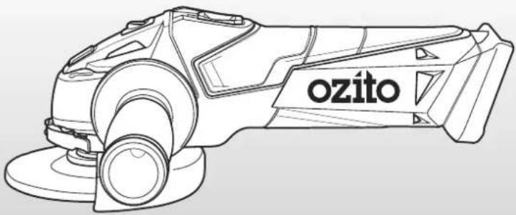
natural_image
Line drawing of a charging tool labeled 'ozito' (no additional text or symbols)WHAT'S IN THE BOX
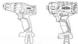
natural_image
Line drawings of two different types of electric drill heads (no text or symbols visible)Cordless Drill Driver
& Impact Driver
Cordless Angle Grinder
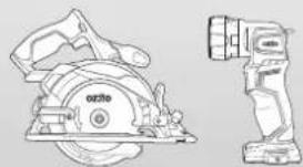
natural_image
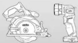
Technical line drawing of a mechanical device with a circular cutter and a cylindrical component (no text or symbols)Cordless Circular Saw & LED Torch
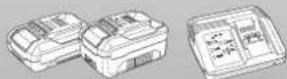
2.0Ah, 4.0Ah Battery & Fast Charger
PX5PAK-005
WARRANTY
IN ORDER TO MAKE A CLAIM UNDER THIS WARRANTY YOU MUST RETURN THE PRODUCT TO YOUR NEAREST BUNNINGS WAREHOUSE WITH YOUR BUNNINGS REGISTER RECEIPT. PRIOR TO RETURNING YOUR PRODUCT FOR WARRANTY PLEASE TELEPHONE OUR CUSTOMER SERVICE HELPLINE:
Australia 1800 069 486
New Zealand 0508 069 486
TO ENSURE A SPEEDY RESPONSE PLEASE HAVE THE MODEL NUMBER AND DATE OF PURCHASE AVAILABLE. A CUSTOMER SERVICE REPRESENTATIVE WILL TAKE YOUR CALL AND ANSWER ANY QUESTIONS YOU MAY HAVE RELATING TO THE WARRANTY POLICY OR PROCEDURE.
WARNING
The following actions will result in the warranty being void.
- If the tool has been operated on a supply voltage other than that specified on the tool.
- If the tool shows signs of damage or defects caused by or resulting from abuse, accidents or alterations.
- Failure to perform maintenance as set out within the instruction manual.
- If the tool is disassembled or tampered with in any way.
The benefits provided under this warranty are in addition to other rights and remedies which are available to you at law.
Our goods come with guarantees that cannot be excluded at law. You are entitled to a replacement or refund for a major failure and for compensation for any other reasonably foreseeable loss or damage. You are also entitled to have the goods repaired or replaced if the goods fail to be of acceptable quality and the failure does not amount to a major failure.
Generally you will be responsible for all costs associated with a claim under this warranty, however, where you have suffered any additional direct loss as a result of a defective product you may be able to claim such expenses by contacting our customer service helpline above.
5 YEAR REPLACEMENT WARRANTY
Your Product is guaranteed for a period of 60 months from the original date of purchase and is intended for DIY (Do It Yourself) use only. If a product is defective it will be replaced in accordance with the terms of this warranty. Lithium Ion batteries and chargers are covered by a 36 month warranty and are excluded from the warranty extension. Warranty excludes consumable parts.
KNOW YOUR PRODUCT
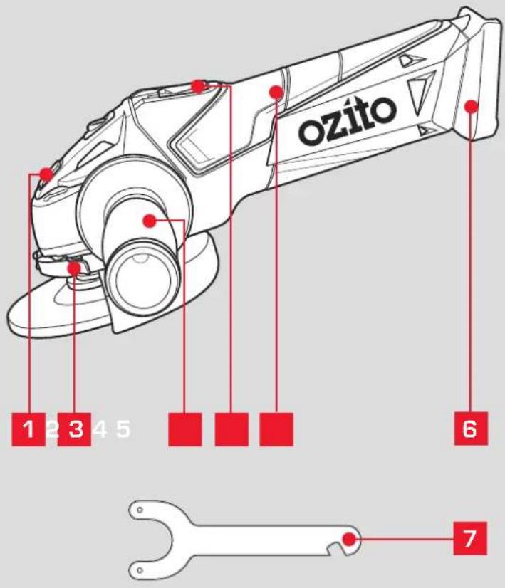
CORDLESS ANGLE GRINDER (PXAGS-500)
1 Spindle Lock
5 Sure Grip Handle
2 Guard Locking Lever
6 Battery Seating
3 Side Handle
7 Pin Wrech
4 Lock On Slide Switch
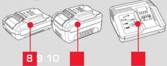
BATTERY & CHARGER
8 2.0Ah Battery
10 Fast Charger
9 4.0Ah Battery
ONLINE MANUAL
Scan this QR Code with your mobile device to take you to the online manual.

SETUP & PREPARATION
1. ASSEMBLY

WARNING! ENSURE THE TOOL IS SWITCHED OFF AND THE BATTERY IS REMOVED BEFORE PERFORMING ANY OF THE FOLLOWING TASKS.
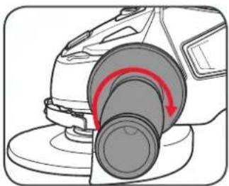
Fitting and Removing the Side Handle
1 To fit, screw the side handle clockwise into 1 of 3 handle positions.
2 To remove, screw the handle anti-clockwise.
natural_image
Diagram of a robotic arm with a red curved arrow indicating motion or force (no text or symbols present)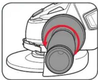
natural_image
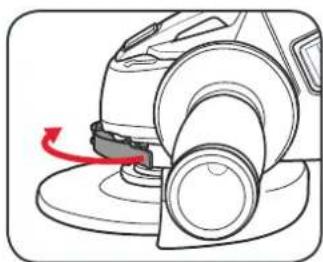
Diagram of a robotic grinding machine with a highlighted circular component (no text or symbols)Adjusting the Safety Guard
1 Loosen the safety guard locking lever to allow it to spin.
2 Rotate the guard into the desired position & secure in place with the locking lever.
natural_image
Diagram of a robotic vacuum cleaner with red motion arrow indicating rotation (no text or symbols)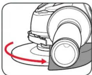
natural_image
Diagram of a mechanical device with a red curved arrow indicating rotational motion (no text or symbols)
WARNING! DO NOT OPERATE THE ANGLE GRINDER WITHOUT THE SAFETY GUARD FITTED AS POSSIBLE INJURIES COULD OCCUR.
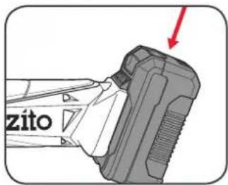
Inserting & Removing the Battery
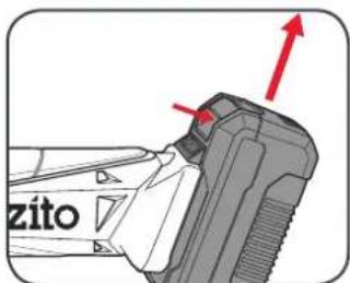
1 Align the ribs of the battery with the recess at the back of the angle grinder & push in until it clicks into place.
2 To remove, press and hold the battery release tab and then slide out.
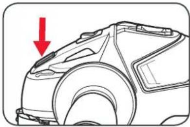
1 Depress and hold the spindle lock to prevent the spindle spinning.
natural_image
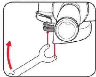
Line drawing of a car's front wheel and side panel, with a red arrow indicating the direction (no text or symbols present)2 Using the pin wrench loosen the flange by rotating it anti-clockwise.
natural_image
Mechanical assembly diagram showing a wrench and nut assembly with red directional arrows indicating motion (no text or symbols)3 Remove the flange and replace the grinding disc on the spindle.
natural_image
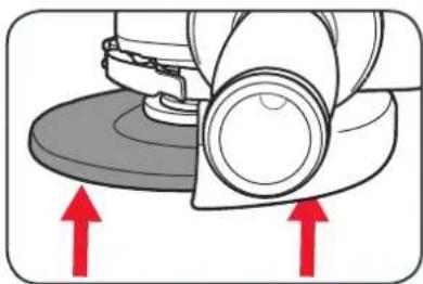
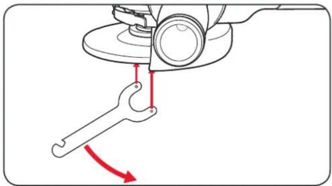
Mechanical component diagram showing a rolling wheel and disc assembly with red arrows indicating upward motion (no text or symbols)4 Screw the flange back onto the spindle and tighten using the pin wrench while holding the spindle lock down.
natural_image
Diagram of a sewing machine's clamping mechanism showing a wrench and hook assembly (no text or symbols)3. BATTERY & CHARGING2. REPLACING A

CAUTION: THE CHARGER FOR THIS PRODUCT SHOULD BE PROTECTED BY A RESIDUAL CURRENT DEVICE (RATED AT 30MA OR LESS).
Charging your lithium ion battery - Fast Charger
1 Connect the charger into a mains power outlet.
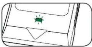
2 The charger LED will flash green showing power is being supplied to the charger.
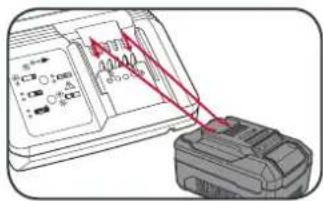
3 With the charger sitting on a flat surface, align the raised ribs on the battery with the recess in the charger and slide onto the charger ensuring a firm connection.
4 The charger LED will illuminate red signifying that the battery is charging.
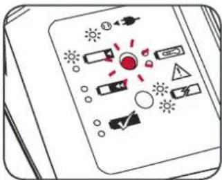
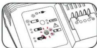
5 The charger LED will illuminate green once the battery is fully charged.
Charger LED Indicator
| LED Indicator Situation | |
| GREEN (Flashing) Stand By (no battery pack is inserted) | |
| RED (Flashing) Battery is charging (low charge) | |
| RED (Illuminated) Battery is charging (mid charge) | |
| GREEN (Illuminated) Battery is fully charged | |
| BOTH(Illuminated) Battery pack is too hot or too cold (charging will begin automatically when battery reaches correct charging temperature). | |
| BOTH (Flashing) Defective battery. Never charge a defective battery pack!Remove battery pack from charger. |
Charging your lithium ion battery - Eco Charger
1 Connect the charger into a mains power outlet.
2 The charger LED will flash green showing power is being supplied to the charger.
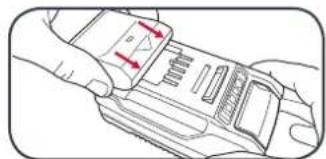
3 With the battery sitting on a flat surface, align the raised ribs on the battery with the recess in the charger and slide onto the battery ensuring a firm connection.
4 The charger LED will illuminate red signifying that the battery is charging.
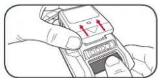
5 When removing the charger from the battery, first press the battery release tab, then slide the charger from its position.
natural_image
Simple line drawing of a device casing with a green indicator light on the lid (no text or symbols)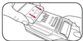
natural_image
Line drawing of a hand holding a device with red arrows indicating motion (no text or symbols)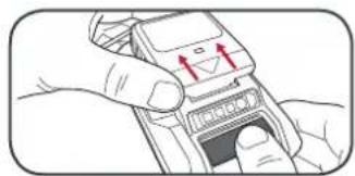
natural_image
Illustration of hands holding a mobile phone with red arrows indicating signal or movement (no text or symbols)Charger LED Indicator
| LED Indicator Situation | |
| GREEN (Flashing) Stand By (no battery pack is inserted) | |
| RED (Illuminated) Battery is charging (low charge) | |
| GREEN (Illuminated) Battery is fully charged | |
| RED (Flashing) Battery or Charger fault | |
| RED & GREEN (Flashing) Battery pack is too hot or too cold (remove battery from charger and store at room temperature 20°C. Insert battery again when at correct charging temperature). If this happens again, the battery is defective and needs to be replaced. |
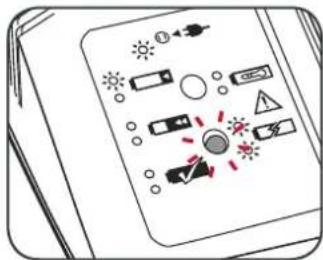
Battery Charge Indicator
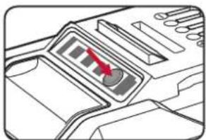
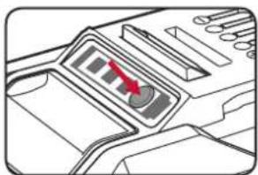
The purchased battery is equipped with a battery charge indicator to show the state of the battery charge.
Press the charge indicator button and look to see which LED lights.
natural_image
Diagram of a device interior with a red arrow pointing to a control panel (no text or symbols visible)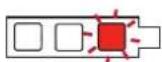
Battery requires immediate charging
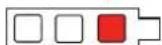
Low state of charge, requires charging soon.
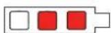
Mid state of charge
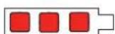
Full state of charge.
Note: The battery needs to be removed from the tool to check the state of charge.
4. GRINDING
Turning On and Off
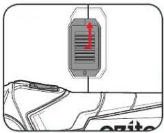
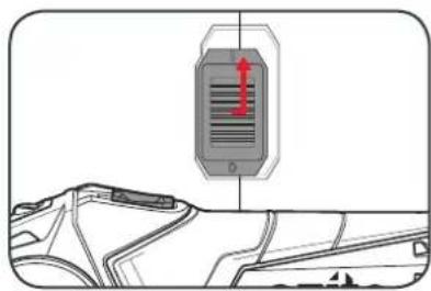
1 To turn on, slide the lock-on switch across to the right and then forward.
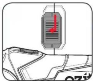
2 To turn off, slide the lock-on switch back and to the left.
Grinding Procedure
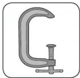
1 Ensure the workpiece is securely held down.
natural_image
Simple illustration of a C-shaped clamp or clamping tool (no text or symbols)2 Hold the angle grinder firmly with both handles and switch on.
natural_image
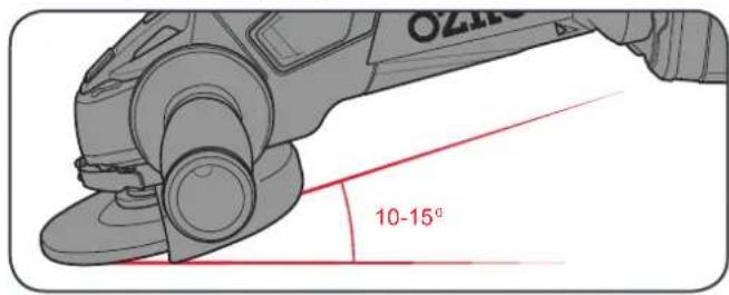
Diagram showing a vehicle interior with a highlighted sensor or sensor device (no text or symbols present)3 Begin grinding your workpiece. The optimum grinding angle is 10-15° to the workpiece.
Note: Do not apply excessive pressure. Allow the tool to do the work, this will prevent deep gouging.
TROUBLESHOOTING
LED lights do not illuminate on charger
Check the charging adaptor is securely plugged into the wall out let.
Check the battery is firmly connected to the charging cradle.
Check that the charging jack is securely connected to the charging cradle.
The battery has a short run time
Ensure the battery is properly charged. It will take 4-5 charging cycles before the battery reaches optimum charge and run time. On the initial charge, the battery requires 5 hours of charging. Subsequent charging only requires 3-5 hours.
Sparking visible through the housing vents
A small amount of sparking may be visible through the housing vents.
This is normal and does not indicate a problem.
Spindle locking button will not depress
The spindle will need to be rotated until the lock can engage. Simply rotate the spindle while applying a small amount of pressure on the spindle lock.
Battery protection system
The tool is equipped with the battery protection system, which helps to ensure a long service life.
The output power automatically cuts off during operation when the tool and/or battery are placed under the following situations:
- When the tool is overloaded:
If this occurs, release the trigger switch and remove causes of overload, then pull the switch trigger again to restart.
- When the remaining battery capacity becomes low:
Recharge the battery pack.
Note: The battery protection system does not in any way damage the tool.
Note: The indicated capacity may be lower than the actual level during use or immediately after using the tool.
MAINTENANCE

WARNING! ALWAYS ENSURE THE TOOL HAS COMPLETELY STOPPED AND THE BATTERY IS REMOVED PRIOR TO ANY MAINTENANCE.
- After each use, blow air through the tool housing to ensure it is free from all dust, dirt, etc. Build up of dust, dirt particles may cause the tool to overheat and shorten the life of the tool.
- If the housing of the angle grinder requires cleaning, do not use solvents but a moist soft cloth or soft brush only.
- Never let any liquid get inside the tool, never immerse any part of the tool into liquid.
- When not in use, the angle grinder should be stored in a dry, frost free location not within the reach of children.
Note: Ozito Industries will not be responsible for any damage or injuries caused by the repair of the angle grinder by an unauthorised person or by mishandling of the angle grinder.
SPARE PARTS
Spare parts can be ordered from the Special Orders Desk at your local Bunnings Warehouse.
For further information, or any parts not listed here, visit www.ozito.com.au or contact Ozito Customer
Service:
Australia 1800 069 486
New Zealand 0508 069 486
E-mail: enquiries@ozito.com.au

BATTERY & CHARGER SAFETY WARNINGS
THIS MANUAL CONTAINS IMPORTANT SAFETY AND OPERATING INSTRUCTIONS FOR YOUR BATTERY CHARGER.
- Before using the charger read all instructions and cautionary markings on the charger, battery pack and the product using the battery pack.
- This charger is not intended for any uses other than charging rechargeable batteries. Any other use may result in risk of fire, electric shock or electrocution.
- Do not place any object on top of the charger or place the charger on a soft surface that may result in excessive internal heat. Place the charger in a position away from any heat source.
- To reduce risk of damage to the electric plug and cord, pull by the plug rather than the cord when disconnecting the charger.
- Make sure the cord is located so that it will not be stepped on, tripped over, or otherwise subjected to damage or stress.
- An extension cord should not be used unless absolutely necessary. Use of an improper extension cord could result in the risk of fire, electric shock or electrocution.
- Do not operate the charger if it has received a sharp blow, been dropped or otherwise damaged in any way. Have it checked by an electrician or power tool repairer.
- Do not disassemble charger. Take it to an electrician or power tool repairer when service or repair is required. Incorrect reassembly may result in a risk of electric shock, electrocution or fire.
- To reduce risk of electric shock, unplug the charger from the outlet before attempting any cleaning. Removing the battery pack will not reduce this risk.
- Never attempt to connect 2 chargers together.
- DO NOT store or use the tool and battery pack in locations where the temperature may reach or exceed 40^ C (such as inside sheds or metal buildings in summer).
- The charger is designed to operate on standard household electrical power (240 volts). Do not attempt to use it on any other voltage!
- The battery pack is not fully charged out of the carton. First read the safety instructions and then follow the charging notes and procedures.
- The longest life and best performance can be obtained if the battery pack is charged when the air temperature is between 18 - 24°C. Do not charge the battery pack in an air temperature below 10°C or above 40°C. This is important and will prevent damage to the battery pack.
- Do not incinerate the battery pack even if it is seriously damaged or is completely worn out. The battery can explode in a fire.
- Never attempt to open the battery pack for any reason. If the plastic housing of the battery pack breaks or cracks, immediately discontinue use and do not recharge.
- During charging, the battery must be placed in a well ventilated area.
DESCRIPTION OF SYMBOLS
| V | Volts | Hz | Hertz |
| ac/~ | Alternating current | Ah | Amp hour |
| dc/-- | Direct current | n_0 | No load speed |
| /min | Revolutions orreciprocation per minute | mA | Milliamperes |
| [2366] | Regulatory ComplianceMark (RCM) | Warning | |
| [czc2] | Read instruction manual | Always wear gloves | |
| [ckd6] | Wear eye protection | Always wear ear, eye anda safety mask |
CARING FOR THE ENVIRONMENT

Power tools that are no longer usable should not be disposed of with household waste but in an environmentally friendly way. Please recycle where facilities exist. Check with your local council authority for recycling advice.

Recycling packaging reduces the need for landfill and raw materials. Reuse of recycled material decreases pollution in the environment. Please recycle packaging where facilities exist. Check with your local council authority for recycling advice.

ELECTRICAL SAFETY

WARNING! When using mains-powered tools, basic safety precautions, including the following, should always be followed to reduce risk of fire, electric shock, personal injury and material damage.
Read the whole manual carefully and make sure you know how to switch the tool off in an emergency, before operating the tool. Save these instructions and other documents supplied with this tool for future reference.
The charger has been designed for 230V and 240V only. Always check that the power supply corresponds to the voltage on the rating plate.
Note: The supply of 230V and 240V on Ozito tools are interchangeable for Australia and New Zealand.

This tools charger is double insulated in accordance with AS/NZS 60745-1; therefore no earth wire is required.
If the supply cord is damaged, it must be replaced by an electrician or a power tool repairer in order to avoid a hazard.
Note: Double insulation does not take the place of normal safety precautions when operating this tool. The insulation system is for added protection against injury resulting from a possible electrical insulation failure within the tool.
The power supply for this products charger should be protected by a residual current device (rated at 30mA
or less). A residual current device reduces the risk of electric shock.

GENERAL POWER TOOL SAFETY WARNINGS

WARNING! Read all safety warnings and all instructions. Failure to follow the warnings and instructions may result in electric shock, fire and/or serious injury.
Save all warnings and instructions for future reference. The term "power tool" in the warnings refers to your mains-operated (corded) power tool or battery-operated (cordless) power
1. Work area safety
a. Keep work area clean and well lit. Cluttered or dark areas invite accidents.
b. Do not operate power tools in explosive atmospheres, such as in the presence of flammable liquids, gases or dust. Power tools create sparks which may ignite the dust or fumes.
c. Keep children and bystanders away while operating a power tool. Distractions can cause you to lose control.
2. Electrical safety
a. Power tool plugs must match the outlet. Never modify the plug in any way. Do not use any adapter plugs with earthed (grounded) power tools. Unmodified plugs and matching outlets will reduce risk of electric shock.
b. Avoid body contact with earthed or grounded surfaces, such as pipes, radiators, ranges and refrigerators. There is an increased risk of electric shock if your body is earthed or grounded.
c. Do not expose power tools to rain or wet conditions. Water entering a power tool will increase the risk of electric shock.
d. Do not abuse the cord. Never use the cord for carrying, pulling or unplugging the power tool. Keep cord away from heat, oil, sharp edges or moving parts. Damaged or entangled cords increase the risk of electric shock.
e. When operating a power tool outdoors, use an extension cord suitable for outdoor use. Use of a cord suitable for outdoor use reduces the risk of electric shock.
f. If operating a power tool in a damp location is unavoidable, use a residual current device (RCD) protected supply. Use of an RCD reduces the risk of electric shock.
3. Personal safety
a. Stay alert, watch what you are doing and use common sense when operating a power tool. Do not use a power tool while you are tired or under the influence of drugs, alcohol or medication. A moment of inattention while operating power tools may result in serious personal injury.
b. Use personal protective equipment. Always wear eye protection. Protective equipment such as dust mask, non-skid safety shoes, hard hat, or hearing protection used for appropriate conditions will reduce personal injuries.
c. Prevent unintentional starting. Ensure the switch is in the off-position before connecting to power source and/or battery pack, picking up or carrying the tool. Carrying power tools with your finger on the switch or energising power tools that have the switch on invites accidents.
d. Remove any adjusting key or wrench before turning the power tool on. A wrench or a key left attached to a rotating part of the power tool may result in personal injury.
e. Do not overreach. Keep proper footing and balance at all times. This enables better control of the
power tool in unexpected situations.
f. Dress properly. Do not wear loose clothing or jewellery. Keep your hair, clothing and gloves away from moving parts. Loose clothes, jewellery or long hair can be caught in moving parts.
g. If devices are provided for the connection of dust extraction and collection facilities, ensure these are connected and properly used. Use of dust collection can reduce dust-related hazards.
4. Power tool use and care
a. Do not force the power tool. Use the correct power tool for your application. The correct power tool will do the job better and safer at the rate for which it was designed.
b. Do not use the power tool if the switch does not turn it on and off. Any power tool that cannot be controlled with the switch is dangerous and must be repaired.
c. Disconnect the plug from the power source and/or the battery pack from the power tool before making any adjustments, changing accessories, or storing power tools. Such preventive safety measures reduce the risk of starting the power tool accidentally.
d. Store idle power tools out of the reach of children and do not allow persons unfamiliar with the power tool or these instructions to operate the power tool. Power tools are dangerous in the hands of untrained users.
e. Maintain power tools. Check for misalignment or binding of moving parts, breakage of parts and any other condition that may affect the power tool's operation. If damaged, have the power tool repaired before use. Many accidents are caused by poorly maintained power tools.
f. Keep cutting tools sharp and clean. Properly maintained cutting tools with sharp cutting edges are less likely to bind and are easier to control.
g. Use the power tool, accessories and tool bits etc. in accordance with these instructions, taking into account the working conditions and the work to be performed. Use of the power tool for operations different from those intended could result in a hazardous situation.
5. Battery tool use and care
a. Recharge only with the charger specified by the manufacturer. A charger that is suitable for one type of battery pack may create a risk of fire when used with another battery pack.
b. Use power tools only with specifically designated battery packs. Use of any other battery packs may create a risk of injury and fire.
c. When battery pack is not in use, keep it away from other metal objects, like paper clips, coins, keys, nails, screws or other small metal objects, that can make a connection from one terminal to another. Shorting the battery terminals together may cause burns or a fire.
d. Under abusive conditions, liquid may be ejected from the battery; avoid contact. If contact accidentally occurs, flush with water. If liquid contacts eyes, additionally seek medical help. Liquid ejected from the battery may cause irritation or burns.
6. Service
a. Have your power tool serviced by a qualified repair person using only identical replacement parts. This will ensure that the safety of the power tool is maintained.

ANGLE GRINDER SAFETY WARNINGS

WARNING! a) This power tool is intended to function as a grinder, sanding or cut-off tool. Read all safety warnings, instructions, illustrations and specifications provided with this power tool.
Failure to follow all instructions listed below may result in electric shock, fir and/or serious injury. b) Operations such as wire brushing, or polishing are not recommended to be performed with this power tool. Operations for which the power tool was not designed may create a hazard and cause personal injury.
c) Do not use accessories which are not specifically designed and recommended by the tool manufacturer. Just because the accessory can be attached to your power tool, it does not assure safe operation.
d) The rated speed of the accessory must be at least equal to the maximum speed marked on the power tool. Accessories running faster than their rated speed can break and fly apart
e) The outside diameter and the thickness of your accessory must be within the capacity rating of your power tool. Incorrectly sized accessories cannot be adequately guarded or controlled.
f) The arbour size of wheels, flanges, backing pads or any other accessory must properly fit the spindle of the power tool. Accessories with arbour holes that do not match the mounting hardware of the power tool will run out of balance, vibrate excessively and may cause loss of control.
g) Do not use a damaged accessory. Before each use inspect the accessory such as abrasive wheels for chips and cracks, backing pad for cracks, tear or excess wear, wire brush for loose or cracked wires. If power tool or accessory is dropped, inspect for damage or install an undamaged accessory. After inspecting and installing an accessory, position yourself and bystanders away from the plane of the rotating accessory and run the power tool at maximum no-load speed for one minute. Damaged accessories will normally break apart during this test time.
h) Wear personal protective equipment. Depending on application, use face shield, safety goggles or safety glasses. As appropriate, wear dust mask, hearing protectors, gloves and workshop apron capable of stopping small abrasive or work piece fragments. The eye protection must be capable of stopping flying debris generated by various operations. The dust mask or respirator must be capable of filtrating particles generated by your operation. Prolonged exposure to high intensity noise may cause hearing loss.
i) Keep bystanders a safe distance away from work area. Anyone entering the work area must wear personal protective equipment. Fragments away and cause injury beyond immediate area of operation.
j) Hold power tool by insulated gripping surfaces only, when performing an operation where the cutting accessory may contact hidden wiring or its own cord. Cutting accessory contacting a "live" wire may make exposed metal parts of the power tool "live" and shock the operator.
k) Never lay the power tool down until the accessory has come to a complete stop. The spinning accessory may grab the surface and pull the power tool out of your control.
I) Do not run the power tool while carrying it at your side. Accidental contact with the spinning accessory could snag your clothing, pulling the accessory into your body.
m) Regularly clean the power tool's air vents. The motor's fan will draw the dust inside the housing and excessive accumulation of powdered metal may cause electrical hazards.
n) Do not operate the power tool near flammable materials. Sparks could ignite these materials.
o) Do not use accessories that require liquid coolants. Using water or other liquid coolants may result in electrocution or shock. Kickback and related warnings
Kickback is a sudden reaction to a pinched or snagged rotating wheel, backing pad, brush or any other accessory. Pinching or snagging causes rapid stalling of the rotating accessory which in turn causes the uncontrolled power tool to be forced in the direction opposite of the accessory's rotation at the point of the binding.
For example, if an abrasive wheel is snagged or pinched by the work piece, the edge of the wheel that is entering into the pinch point can dig into the surface of the material causing the wheel to climb out or kick out. The wheel may either jump toward or away from the operator, depending on direction of the wheel's movement at the point of pinching. Abrasive wheels may also break under these conditions. Kickback is the result of power tool missusa and/or incorrect operating procedures or conditions and can be avoided by taking proper precautions as given below.
a) Maintain a firm grip on the power tool and position your body and arm to allow you to resist kickback forces. Always use auxiliary handle, if provided, for maximum control over kickback or torque reaction during start-up. The operator can control torque reactions or kickback forces, if proper precautions are taken.
b) Never place your hand near the rotating accessory. Accessory may kickback over your hand.
c) Do not position your body in the area where power tool will move if kickback occurs. Kickback will propel the tool in direction opposite to the wheel's movement at the point of snagging.
d) Use special care when working corners, sharp edges etc. Avoid bouncing and snagging the accessory. Corners, sharp edges or bouncing have a tendency to snap the rotating accessory and cause loss of control or kickback.
e) Do not attach a saw chain woodcarving blade or toothed saw blade. Such blades create frequent kickback and loss of control.
Additional safety instructions for grinding and abrasive cutting-off operations
a) Use only wheel types that are recommended for your power tool and the specific guard designed for the selected wheel. Wheels for which the power tool was not designed cannot be adequately guarded and are unsafe.
b) The guard must be securely attached to the power tool and positioned for maximum safety, so the least amount of wheel is exposed towards the operator. The guard helps to protect operator from broken wheel fragments and accidental contact with wheel.
c) Wheels must be used only for recommended applications. For example: do not grind with the side of cut-off wheel. Abrasive cut-off wheels are intended for peripheral grinding, side forces applied to these wheels may cause them to shatter. d) Always use undamaged wheel flanges that are of correct size and shape for your selected wheel. Proper wheel flanges support the wheel thus reducing the possibility of wheel breakage. Flanges for cut-off wheels may be different from grinding wheel flances.
e) Do not use worn down wheels from larger power tools. Wheel intended for larger power tool is not suitable for the higher speed of a smaller tool and may burst.
Additional safety instructions for abrasive cutting-off operations:
a) Do not "jam" the cut-off wheel or apply excessive pressure. Do not attempt to make an excessive depth of cut. Overstressing the wheel increases the loading and susceptibility to twisting or binding of the wheel in the cut and the possibility of kickback or wheel breakage.
b) Do not position your body in line with and behind the rotating wheel. When the wheel, at the point of operation, is moving away from your body, the possible kickback may propel the spinning wheel and the power tool directly at you. c) When wheel is binding or when interrupting a cut for any reason, switch off the power tool and hold the power tool motionless until the wheel comes to a complete stop. Never attempt to remove the cut-off wheel from the cut while the wheel is in motion otherwise kickback may occur. Investigate and take corrective action to eliminate the cause of wheel binding.
d) Do not restart the cutting operation in the work piece. Let the wheel reach full speed and carefully reenter the cut. The wheel may bind, walk up or kickback if the power tool is restarted in the work piece.
e) Support panels or any oversized work piece to minimize the risk of wheel pinching and kickback. Large work pieces tend to sag under their own weight. Supports must be placed under the work piece near the line of cut and near the edge of the work piece on both sides of the wheel.
f) Use extra caution when making a "pocket cut" into existing walls or other blind areas. The protruding wheel may cut gas or water pipes, electrical wiring or objects that can cause kickback.
Additional safety instructions for sanding operations
a) Do not use excessively oversized sanding disc paper. Follow manufacturers recommendations, when selecting sanding paper. Larger sanding paper extending beyond the sanding pad presents a laceration hazard and may cause snagging, tearing of the disc or kickback.
We highly recommend that when using abrasive cutting wheels, that a cutting guard should be fitted to your angle grinder. These cutting guards are available as a spare part and can be ordered through the special orders desk

18V LITHIUM ION
CORDLESS CIRCULAR SAW
INSTRUCTION MANUAL
SPECIFICATIONS
Voltage: 18V
No Load Speed: 4,200/min
Blade Diameter: 150mm (6")
Blade Bore: 10mm
Depth of Cut: 48mm @ 90°
32mm @ 45°
Charge Time: 40mins (2.0Ah)
80mins (4.0Ah)
Weight: 2.4kg
ozito.com.au
5YEAR REPLACEMENT WARRANTY
natural_image
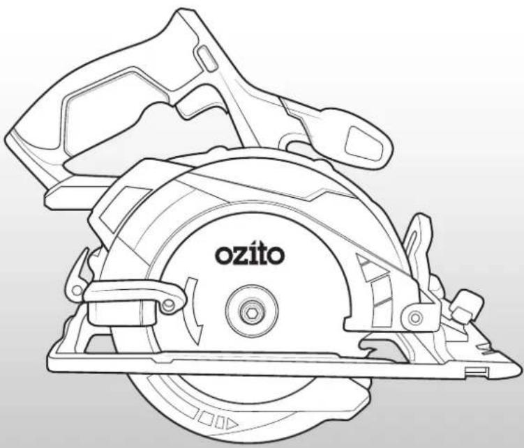
Line drawing of a cut-out saw with 'ozito' branding on the blade (no additional text or symbols)WHAT'S IN THE BOX
natural_image
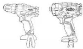
Line drawings of two different types of OZito electric drillers (no text or symbols present)Cordless Drill Driver
& Impact Driver
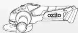
Cordless Angle Grinder
natural_image
Technical line drawing of a mechanical device with a circular cutter and a cylindrical tool (no text or symbols)Cordless Circular Saw
& LED Torch
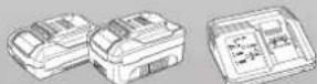
2.0Ah, 4.0Ah Battery & Fast
Charger
PX5PAK-005
WARRANTY
IN ORDER TO MAKE A CLAIM UNDER THIS WARRANTY YOU MUST RETURN THE PRODUCT TO YOUR NEAREST BUNNINGS WAREHOUSE WITH YOUR BUNNINGS REGISTER RECEIPT. PRIOR TO RETURNING YOUR PRODUCT FOR WARRANTY PLEASE TELEPHONE OUR CUSTOMER SERVICE HELPLINE:
Australia 1800 069 486
New Zealand 0508 069 486
TO ENSURE A SPEEDY RESPONSE PLEASE HAVE THE MODEL NUMBER AND DATE OF PURCHASE AVAILABLE. A CUSTOMER SERVICE REPRESENTATIVE WILL TAKE YOUR CALL AND ANSWER ANY QUESTIONS YOU MAY HAVE RELATING TO THE WARRANTY POLICY OR PROCEDURE.
WARNING
The following actions will result in the warranty being void.
- If the tool has been operated on a supply voltage other than that specified on the tool.
- If the tool shows signs of damage or defects caused by or resulting from abuse, accidents or alterations.
- Failure to perform maintenance as set out within the instruction manual.
- If the tool is disassembled or tampered with in any way.
The benefits provided under this warranty are in addition to other rights and remedies which are available to you at law.
Our goods come with guarantees that cannot be excluded at law. You are entitled to a replacement or refund for a major failure and for compensation for any other reasonably foreseeable loss or damage. You are also entitled to have the goods repaired or replaced if the goods fail to be of acceptable quality and the failure does not amount to a major failure.
Generally you will be responsible for all costs associated with a claim under this warranty, however, where you have suffered any additional direct loss as a result of a defective product you may be able to claim such expenses by contacting our customer service helpline above.
5 YEAR REPLACEMENT WARRANTY
Your Product is guaranteed for a period of 60 months from the original date of purchase and is intended for DIY (Do It Yourself) use only. If a product is defective it will be replaced in accordance with the terms of this warranty. Lithium Ion
batteries and chargers are covered by a 36 month
warranty and are excluded from the warranty extension. Warranty excludes consumable parts, for example: cutting blades.
KNOW YOUR PRODUCT
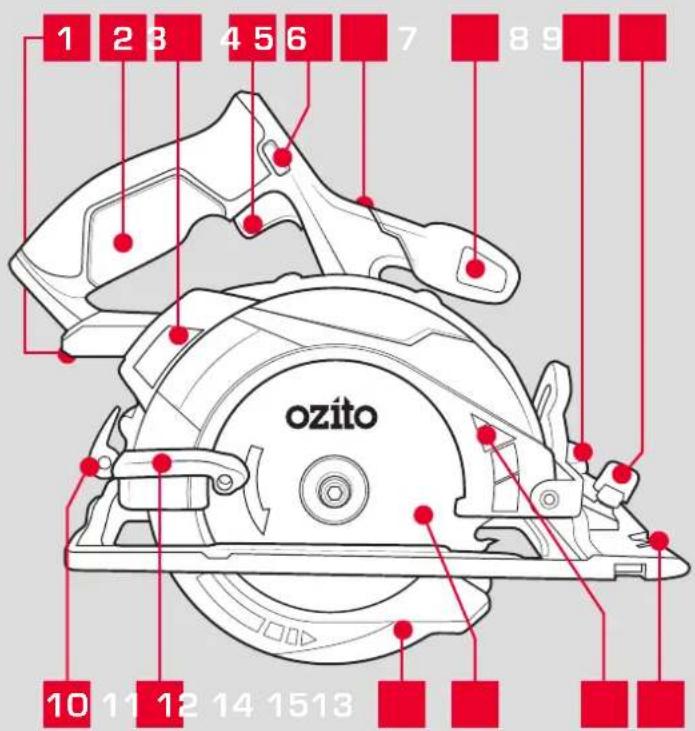
CORDLESS CIRCULAR SAW (PXCSS-500)
1 Battery Seating
9 Rip Fence Locking Knob
2 Rear Handle
10 Depth Locking Lever
3 Dust Port
11 Blade Guard Lever
4 On/Off Trigger
12 Lower Blade Guard
5 Lock-Off Lever
13 Blade
6 Hex Key Holder
14 Upper Blade Guard
7 Front Handle
15 Cutting Guide Notch
8 Bevel Locking Knob
BATTERY & CHARGER
16 2.0Ah Battery
18 Fast Charger
17 4.0Ah Battery
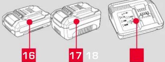
For optimal performance, we recommend the use of a 3.0Ah battery or higher to operate this Power X Change Circular Saw.
ONLINE MANUAL
Scan this QR Code with your mobile device to take you to the online manual.

SETUP & PREPARATION
1. BATTERY & CHARGING

CAUTION: THE CHARGER FOR THIS PRODUCT SHOULD BE PROTECTED BY A RESIDUAL CURRENT DEVICE (RATED AT 30MA OR LESS).
The purchased battery will be shipped in a low charge condition, and requires charging prior to use. Allow several cycles of charging and discharging (through use of the tool) for the battery to reach its optimum performance / runtime.
Charging your lithium ion battery - Fast Charger
1 Connect the charger into a mains power outlet.
2 The charger LED will flash green showing power is being supplied to the charger.
3 With the charger sitting on a flat surface, align the raised ribs on the battery with the recess in the charger and slide onto the charger ensuring a firm connection.
4 The charger LED will illuminate red signifying that the battery is charging.
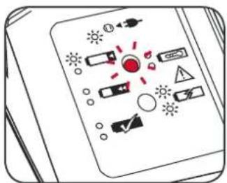
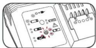
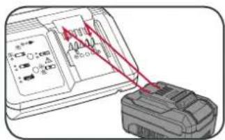
5 The charger LED will illuminate green once the battery is fully charged.
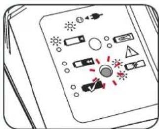
Charger LED Indicator
| LED Indicator Situation | |
| GREEN (Flashing) Stand By (no battery pack is inserted) | |
| RED (Flashing) Battery is charging (low charge) | |
| RED (Illuminated) Battery is charging (mid charge) | |
| GREEN (Illuminated) Battery is fully charged | |
| BOTH(Illuminated) Battery pack is too hot or too cold (charging will begin automatically when battery reaches correct charging temperature). | |
| BOTH (Flashing) Defective battery. Never charge a defective battery pack!Remove battery pack from charger. |
Charging your lithium ion battery - Eco Charger
1 Connect the charger into a mains power outlet.
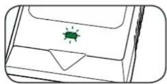
2 The charger LED will flash green showing power is being supplied to the charger.
3 With the battery sitting on a flat surface, align the raised ribs on the battery with the recess in the charger and slide onto the battery ensuring a firm connection.
4 The charger LED will illuminate red signifying that the battery is charging.
5 When removing the charger from the battery, first press the battery release tab, then slide the charger from its position.
natural_image
Simple line drawing of a device casing with a green insect icon on the cover (no text or symbols)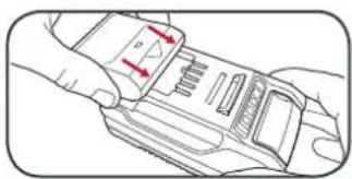
natural_image
Line drawing of a hand holding a device with red arrows indicating motion or force (no text or symbols)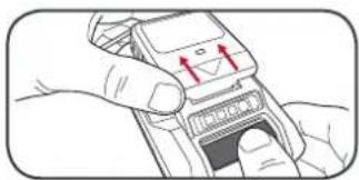
natural_image
Illustration of hands using a handheld device to interact with a screen (no text or symbols visible)Charger LED Indicator
| LED Indicator Situation | |
| GREEN (Flashing) Stand By (no battery pack is inserted) | |
| RED (Illuminated) Battery is charging (low charge) | |
| GREEN (Illuminated) Battery is fully charged | |
| RED (Flashing) Battery or Charger fault | |
| RED & GREEN (Flashing) Battery pack is too hot or too cold (remove battery from charger and store at room temperature 20°C. Insert battery again when at correct charging temperature). If this happens again, the battery is defective and needs to be replaced. |
Battery Charge Indicator
The purchased battery is equipped with a battery charge indicator to show the state of the battery charge.
Press the charge indicator button and look to see which LED lights.
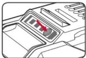
natural_image
Diagram of a device interior with a red arrow pointing to a control panel (no text or symbols visible)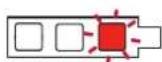
Battery requires immediate charging
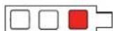
Low state of charge, requires charging soon.
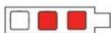
Mid state of charge
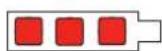
Full state of charge.
Note: The battery needs to be removed from the tool to check the state of charge.
2. FITTING THE BATTERY & GUIDE
Inserting & Removing the Battery
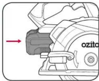
1 Slide the battery into the seating at the back of the saw until it clicks into place.
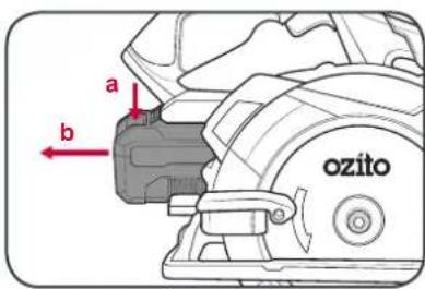
2 To remove, press and hold the battery release tab and then slide out.
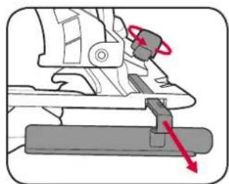
Attaching the Rip Fence
The rip fence allows you to perform straight cuts with ease.
1 Insert the rip fence through the rip fence slots in the front of the baseplate.
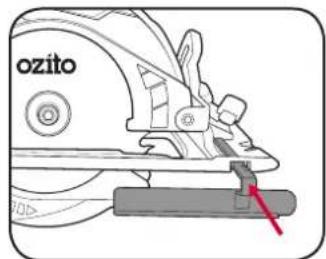
2 Once the desired width is set, tighten the locking knob to secure in place.
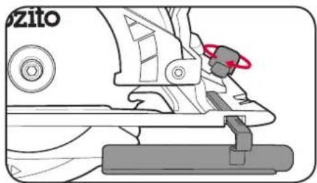
natural_image
Mechanical assembly diagram showing a clamping mechanism with a red-handled ring (no text or symbols)3 To remove, loosen the locking knob and then slide the rip fence out.
natural_image
Mechanical assembly diagram showing a lever mechanism with red arrows indicating motion direction (no text or symbols)3. DEPTH & BEVEL ADJUSTMENT

WARNING: ENSURE THE TOOL IS SWITCHED OFF AND THE BATTERY IS REMOVED BEFORE PERFORMING ANY OF THE FOLLOWING TASKS.
Depth Adjustment
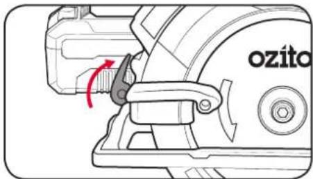
Depth should be adjusted so that no more than one tooth is protruding through the timber. This helps to minimise splintering.
1 Loosen the depth adjustment lever.
2 Hold the baseplate down with one hand. Raise or lower the saw to the desired depth.
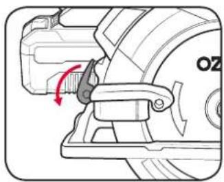
natural_image
Mechanical assembly diagram showing a rotating component with a red arrow indicating rotation (no text or symbols)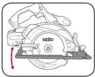
3Tightendepth adjustment knob to secure in place.
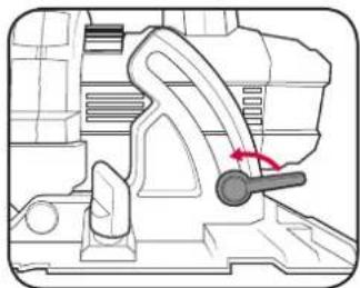
Bevel Adjustment
1 Loosen bevel adjustment knob.
2 Align baseplate to desired angle on bevel scale.
natural_image
Technical line drawing of a mechanical component with a handle and arrow indicating motion (no text or symbols)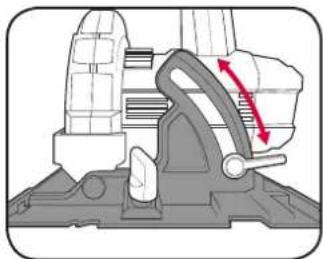
natural_image
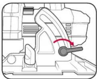
Mechanical assembly diagram showing a clamping mechanism with red directional arrows indicating motion (no text or symbols present)3 Tighten the bevel adjustment knob.
natural_image
Technical line drawing of a mechanical component with a curved handle and arrow indicating motion (no text or symbols)4. CONTROLS
Turning On and Off
1 Press and hold the lock-off level in either direction.
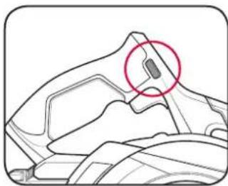
natural_image
Technical line drawing of a mechanical component with a highlighted circular detail (no text or symbols)2 Squeeze the on/off trigger to start the saw.
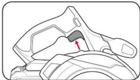
natural_image
Technical line drawing of a mechanical component with a red arrow indicating a specific feature (no text or symbols present)Note: Allow the saw to reach full speed before beginning a cut.
3 To stop the saw, release the on/off trigger.
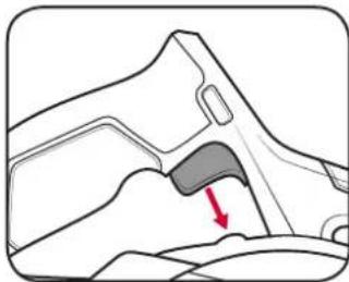
natural_image
Diagram of a mechanical component with a red arrow indicating a specific area (no text or symbols present)
WARNING AFTER USE, HOLD THE SAW AWAY FROM YOUR BODY UNTIL THE BLADE STOPS COMPLETELY.
Cutting Guide Notch
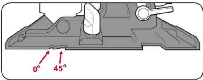
The cutting guide will give an approximate line of cut. For a straight cut, use the 0^ notch. For a 45^ cut, use the 45^ notch. For higher accuracy, use the rip fence provided.
5. MAKING A CUT 6. BLADE FITMENT
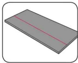
1 Mark the cutting line on the work piece.
natural_image
3D rendering of a rectangular plate with a red diagonal line on top (no text or symbols)2 Adjust the saw depth and bevel angle for the desired cut.
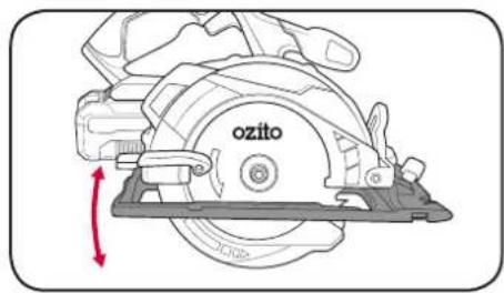
3 Attach the rip fence for an additional guide.
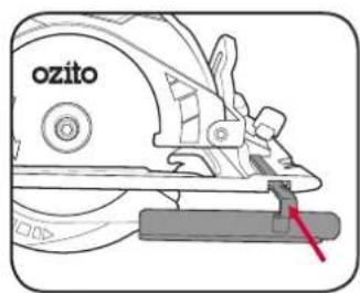
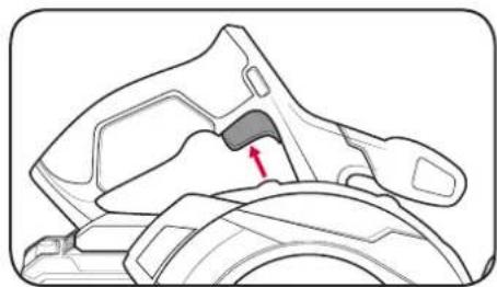
4 Hold the saw securely with both hands and start the tool.
natural_image
Technical line drawing of a mechanical component with a red arrow indicating a specific feature (no text or symbols present)Note: Allow the saw to reach full speed before beginning a cut.
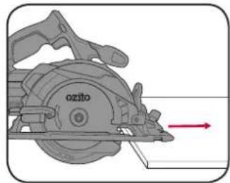
5 Move the saw through the material to perform the cut. Once complete, release the on/off trigger and remove the saw from the work piece.
natural_image
Mechanical diagram of a cutaway view of a saw blade assembly with no visible text or symbolsNote: Never force the saw. Use light and continuous pressure.
The tool is recommended for wood cutting only and is not recommended for use with abrasive wheels or masonry/diamond cutting wheels. Only use 150mm wood cutting blades.
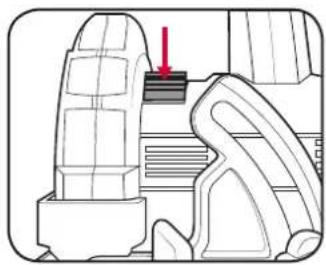
1 Press and hold the spindle lock.
2 Use hex key to rotate blade until lock engages. Remove blade bolt and outer blade flange.
natural_image
Technical line drawing of a mechanical component with a red arrow indicating a specific feature (no text or symbols present)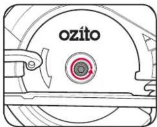
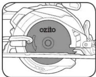
3 Retract lower blade guard fully.
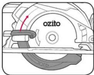
4 Remove and replace blade. Ensure arrows on the blade point in the same direction as the arrow on the upper blade guard.
natural_image
Technical line drawing of a mechanical component with 'ozito' label, no readable text or symbols beyond the label5 Fit outer blade flange and blade bolt.
6 Depress spindle lock and Tighten blade bolt with the hex key.
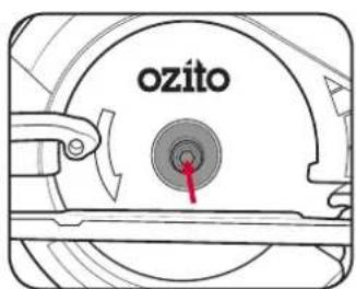
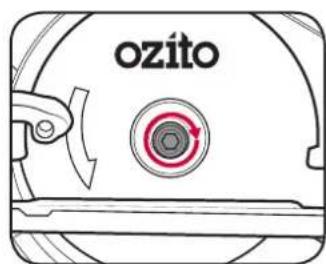

WARNING! ALWAYS ENSURE THE TOOL HAS COMPLETELY STOPPED AND THE BATTERY IS REMOVED PRIOR TO ANY MAINTENANCE.
- Keep ventilation slots of the circular saw clean at all times to ensure efficient operation.
- After each use, blow air through the tool housing to ensure it is free from all dust, dirt, etc. Build up of dust, dirt particles may cause the tool to overheat and shorten the life of the tool.
- If the housing of the circular saw requires cleaning, do not use solvents but a moist soft cloth or soft brush only.
- Never let any liquid get inside the tool, never immerse any part of the tool into liquid.
- No lubrication is necessary as the tool has sealed bearings.
- When not in use, the circular saw should be stored in a dry, frost free location not within the reach of children.
Note: Ozito Industries will not be responsible for any damage or injuries caused by the repair of the circular saw by an unauthorised person or by mishandling of the circular saw.
Battery protection system
The tool is equipped with the battery protection system, which helps to ensure a long service life.
The output power automatically cuts off during operation when the tool and/or battery are placed under the following situations:
- When the tool is overloaded:
If this occurs, release the trigger switch and remove causes of overload, then pull the switch trigger again to restart.
- When the remaining battery capacity becomes low:
Recharge the battery pack.
Note: The battery protection system does not in any way damage the tool.
Note: The indicated capacity may be lower than the actual level during use or immediately after using the tool.
LED lights do not illuminate on charger
Check the charging adaptor is securely plugged into the wall out let.
Check the battery is firmly connected to the charging cradle.
Check that the charging jack is securely connected to the charging cradle.
The battery has a short run time
Ensure the battery is properly charged. It will take 4-5 charging cycles before the battery reaches optimum charge and run time. On the initial charge, the battery requires 5 hours of charging. Subsequent charging only requires 3-5 hours.
Sparking visible through the housing air vents
A small amount of sparking may be visible through the housing vents. This is normal and does not indicate a problem.
Circular Saw Tips
Always hold the soft grip handle with one hand and the front handle with the other.
Maintain a firm grip and operate the on/off switch with a positive action.
Never force the saw. Use light and continuous pressure.
When cutting is interrupted, to resume cutting, depress the lock-off button and squeeze the on/off switch and allow the blade to reach full speed, re-enter the cut slowly and resume cutting.
When cutting across the grain, the fibres of the wood have a tendency to tear and lift. Advancing the saw slowly minimizes this effect. For a finished cut, a cross cut blade or mitre blade is recommended.
DESCRIPTION OF SYMBOLS
| V | Volts | Hz | Hertz |
| ac/~ | Alternating current | W | Watts |
| dc/--D | rect current | ∅ | Diameter |
| mA | Milliamperes | Ah | Amp hour |
 | Do not expose to rain. | No | No load speed |
 | Regulatory Compliance Mark (RCM) |  Load (MEPS) Load (MEPS) | Transformer Energy Rating (MEPS) |
 | Warning | [6AHZ] | Read instruction manual |
 | Double insulated |  | Indoor use only |
 | Lithium Ion battery |  Pumped Pumped | Do not use or store battery in temperatures exceeding 50°C |
 | Recycle battery Do not put |  | e rubbish |
 | Do not incinerate Do not put |  | ttery wet |
 | Thermal cut-out protection |
SPARE PARTS
Spare parts can be ordered from the Special Orders Desk at your local Bunnings Warehouse.
For further information, or any parts not listed here, visit www.ozito.com.au or contact Ozito Customer
Service:
Australia 1800 069 486
New Zealand 0508 069 486
E-mail: enquiries@ozito.com.au

BATTERY AND CHARGER SAFETY WARNINGS
THIS MANUAL CONTAINS IMPORTANT SAFETY AND OPERATING INSTRUCTIONS FOR YOUR BATTERY CHARGER.
- Before using the charger read all instructions and cautionary markings on the charger, battery pack and the product using the battery pack.
- This charger is not intended for any uses other than charging rechargeable batteries. Any other use may result in risk of fire, electric shock or electrocution.
- Do not place any object on top of the charger or place the charger on a soft surface that may result in excessive internal heat. Place the charger in a position away from any heat source.
- To reduce risk of damage to the electric plug and cord, pull by the plug rather than the cord when disconnecting the charger.
- Make sure the cord is located so that it will not be stepped on, tripped over, or otherwise subjected to damage or stress.
- An extension cord should not be used unless absolutely necessary. Use of an improper extension cord could result in the risk of fire, electric shock or electrocution.
- Do not operate the charger if it has received a sharp blow, been dropped or otherwise damaged in any way. Have it checked by an electrician or power tool repairer.
- Do not disassemble charger. Take it to an electrician or power tool repairer when service or repair is required. Incorrect reassembly may result in a risk of electric shock, electrocution or fire.
- To reduce risk of electric shock, unplug the charger from the outlet before attempting any cleaning. Removing the battery pack will not reduce this risk.
- Never attempt to connect 2 chargers together.
- DO NOT store or use the tool and battery pack in locations where the temperature may reach or exceed 40°C (such as inside sheds or metal buildings in summer).
- The charger is designed to operate on standard household electrical power (240 volts). Do not attempt to use it on any other voltage!
- The battery pack is not fully charged out of the carton. First read the safety instructions and then follow the charging notes and procedures.
- The longest life and best performance can be obtained if the battery pack is charged when the air temperature is between 18 - 24°C. Do not charge the battery pack in an air temperature below 10°C or above 40°C. This is important and will prevent damage to the battery pack.
- Do not incinerate the battery pack even if it is seriously damaged or is completely worn out. The battery can explode in a fire.
- Never attempt to open the battery pack for any reason. If the plastic housing of the battery pack breaks or cracks, immediately discontinue use and do not recharge.
- During charging, the battery must be placed in a well ventilated area.
CARING FOR THE ENVIRONMENT

Power tools that are no longer usable should not be disposed of with household waste but in an environmentally friendly way. Please recycle where facilities exist. Check with your local council authority for recycling advice.
Recycling packaging reduces the need for landfill and raw materials. Reuse of recycled material decreases pollution in the environment. Please recycle packaging where facilities exist. Check with your local council authority for recycling advice.

ELECTRICAL SAFETY

WARNING! When using mains-powered tools, basic safety precautions, including the following, should always be followed to reduce risk of fire, electric shock, personal injury and material damage.
Read the whole manual carefully and make sure you know how to switch the tool off in an emergency, before operating the tool. Save these instructions and other documents supplied with this tool for future reference.
The charger has been designed for 230V and 240V only. Always check that the power supply corresponds to the voltage on the rating plate.
Note: The supply of 230V and 240V on Ozito tools are interchangeable for Australia and New Zealand.

This tools charger is double insulated; therefore no earth wire is required.
If the supply cord is damaged, it must be replaced by an electrician or a power tool repairer in order to avoid a hazard.
Note: Double insulation does not take the place of normal safety precautions when operating this tool. The insulation system is for added protection against injury resulting from a possible electrical insulation failure within the tool.
Using an Extension Lead
Always use an approved extension lead suitable for the power input of this tool. Before use, inspect the extension lead for signs of damage, wear and ageing. Replace the extension lead if damaged or defective.
When using an extension lead on a reel, always unwind the lead completely. Use of an extension lead not suitable for the power input of the tool or which is damaged or defective may result in a risk of fire and electric shock.
The power supply for this products charger should be protected by a residual current device (rated at 30mA or less). A residual current device reduces the risk of electric shock.

GENERAL POWER TOOL SAFETY WARNINGS

WARNING! Read all safety warnings and all instructions. Failure to follow the warnings and instructions may result in electric shock, fire and/or serious injury.
Save all warnings and instructions for future reference. The term "power tool" in the warnings refers to your mains-operated (corded) power tool or battery-operated (cordless) power tool.
- Work area safety
a. Keep work area clean and well lit. Cluttered or dark areas invite accidents.
b. Do not operate power tools in explosive atmospheres, such as in the presence of flammable liquids, gases or dust. Power tools create sparks which may ignite the dust or fumes.
c. Keep children and bystanders away while operating a power tool. Distractions can cause you to lose control.
- Electrical safety
a. Power tool plugs must match the outlet. Never modify the plug in any way. Do not use any adapter plugs with earthed (grounded) power tools. Unmodified plugs and matching outlets will reduce risk of electric shock.
b. Avoid body contact with earthed or grounded surfaces, such as pipes, radiators, ranges and refrigerators. There is an increased risk of electric shock if your body is earthed or grounded.
c. Do not expose power tools to rain or wet conditions. Water entering a power tool will increase the risk of electric shock.
d. Do not abuse the cord. Never use the cord for carrying, pulling or unplugging the power tool. Keep cord away from heat, oil, sharp edges or moving parts. Damaged or entangled cords increase the risk of electric shock.
e. When operating a power tool outdoors, use an extension cord suitable for outdoor use. Use of a cord suitable for outdoor use reduces the risk of electric shock.
f. If operating a power tool in a damp location is unavoidable, use a residual current device (RCD) protected supply. Use of an RCD reduces the risk of electric shock.
- Personal safety
a. Stay alert, watch what you are doing and use common sense when operating a power tool. Do not use a power tool while you are tired or under the influence of drugs, alcohol or medication. A moment of inattention while operating power tools may result in serious personal injury.
b. Use personal protective equipment. Always wear eye protection. Protective equipment such as dust mask, non-skid safety shoes, hard hat, or hearing protection used for appropriate conditions will reduce personal injuries.
c. Prevent unintentional starting. Ensure the switch is in the off-position before connecting to power source and/or battery pack, picking up or carrying the tool. Carrying power tools with your finger on the switch or energising power tools that have the switch on invites accidents.
d. Remove any adjusting key or wrench before turning the power tool on. A wrench or a key left attached to a rotating part of the power tool may result in personal injury.
e. Do not overreach. Keep proper footing and balance at all times. This enables better control of the power tool in unexpected situations.
f. Dress properly. Do not wear loose clothing or jewellery. Keep your hair, clothing and gloves away from moving parts. Loose clothes, jewellery or long hair can be caught in moving parts.
g. If devices are provided for the connection of dust extraction and collection facilities, ensure these are connected and properly used. Use of dust collection can reduce dust-related hazards.
- Power tool use and care
a. Do not force the power tool. Use the correct power tool for your application. The correct power tool will do the job better and safer at the rate for which it was designed.
b. Do not use the power tool if the switch does not turn it on and off. Any power tool that cannot be controlled with the switch is dangerous and must be repaired.
c. Disconnect the plug from the power source and/or the battery pack from the power tool before making any adjustments, changing accessories, or storing power tools. Such preventive safety measures reduce the risk of starting the power tool accidentally.
d. Store idle power tools out of the reach of children and do not allow persons unfamiliar with the power tool or these instructions to operate the power tool. Power tools are dangerous in the hands of untrained users.
- Maintain power tools. Check for misalignment or binding of moving parts, breakage of parts and any other condition that may affect the power tool's operation. If damaged, have the power tool repaired before use. Many accidents are caused by poorly maintained power tools.
f. Keep cutting tools sharp and clean. Properly maintained cutting tools with sharp cutting edges are less likely to bind and are easier to control.
g. Use the power tool, accessories and tool bits etc. in accordance with these instructions, taking into account the working conditions and the work to be performed. Use of the power tool for operations different from those intended could result in a hazardous situation.
- Battery tool use and care
a. Recharge only with the charger specified by the manufacturer. A charger that is suitable for one type of battery pack may create a risk of fire when used with another battery pack.
b. Use power tools only with specifically designated battery packs. Use of any other battery packs may create a risk of injury and fire.
c. When battery pack is not in use, keep it away from other metal objects, like paper clips, coins, keys, nails, screws or other small metal objects, that can make a connection from one terminal to another. Shorting the battery terminals together may cause bums or a fire.
d. Under abusive conditions, liquid may be ejected from the battery; avoid contact. If contact accidentally occurs, flush with water. If liquid contacts eyes, additionally seek medical help. Liquid ejected from the battery may cause irritation or burns.
- Service
a. Have your power tool serviced by a qualified repair person using only identical replacement parts. This will ensure that the safety of the power tool is maintained.

CIRCULAR SAW SAFETY WARNINGS

WARNING!
a) Keep hands away from cutting area and the blade. Keep your second hand on auxiliary handle, or motor housing. If both hands are holding the saw, they cannot be cut by the blade.
b) Do not reach underneath the workpiece. The guard cannot protect you from the blade below the workpiece.
c) Adjust the cutting depth to the thickness of the workpiece. Less than a full tooth of the blade teeth should be visible below the workpiece.
d) Never hold piece being cut in your hands or across your leg. Secure the workpiece to a stable platform. It is important to support the work properly to minimize body exposure, blade binding, or loss of control.
e) Hold power tool by insulated gripping surfaces when performing an operation where the cutting tool may contact hidden wiring. Contact with a "live" wire will also make exposed metal parts of the power tool "live" and shock the operator.
f) When ripping always use a rip fence or straight edge guide. This improves the accuracy of cut and reduces the chance of blade binding.
g) Always use blades with correct size and shape (diamond versus round) of arbour holes. Blades that do not match the mounting hardware of the saw will run eccentrically, causing loss of control.
h) Never use damaged or incorrect blade washers or bolt. The blade washers and bolt were specially designed for your saw, for optimum performance and safety of operation.
Further safety instructions for all saws
Causes and operator prevention of kickback:
- Kickback is a sudden reaction to a pinched, bound or misaligned saw blade, causing an uncontrolled saw to lift up and out of the workpiece toward the operator;
- When the blade is pinched or bound tightly by the kerf closing down, the blade stalls and the motor reaction drives the unit rapidly back toward the operator;
- If the blade becomes twisted or misaligned in the cut, the teeth at the back edge of the blade can dig into the top surface of the wood causing the blade to climb out of the korf and jump back toward the operator.
Kickback is the result of saw misuse and/or incorrect operating procedures or conditions and can be avoided by taking proper precautions as given below.
a) Maintain a firm grip with both hands on the saw and position your arms to resist kickback forces. Position your body to either side of the blade, but not in line with the blade. Kickback could cause the saw to jump backwards, but kickback forces can be controlled by the operator, if proper precautions are taken.
b) When blade is binding, or when interrupting a cut for any reason, release the trigger and hold the saw motionless in the material until the blade comes to a complete stop. Never attempt to remove the saw from the work or pull the saw backward while the blade is in motion or kickback may occur. Investigate and take corrective actions to eliminate the cause of blade binding.
When restarting a saw in the workpiece, centre the saw blade in the kerf and check that saw teeth are not engaged into the material. If saw blade is binding, it may walk up or kickback from the workpiece as the saw is restarted.
d) Support large panels to minimise the risk of blade pinching and kickback. Large panels tend to sag under their own weight. Supports must be placed under the panel on both sides, near the line of cut and near the edge of the panel.
e) Do not use dull or damaged blades. Blunt or improperly set blades produce narrow kerf causing excessive friction, blade binding and kickback.
f) Blade depth and bevel adjusting locking levers must be tight and secure before making cut. If blade adjustment shifts while cutting, it may cause binding and kickback.
g] Use extra caution when making a "plunge cut" into existing walls or other blind areas. The protruding blade may cut objects that can cause kickback.
h) Check lower guard for proper closing before each use. Do not operate the saw if lower guard does not move freely and close instantly. Never clamp or tie the lower guard into the open position. If saw is accidentally dropped, lower guard may be bent. Raise the lower guard with the retracting handle and make sure it moves freely and does not touch the blade or any other part, in all angles and depths of cut.
i) Check the operation of the lower guard spring. If the guard and the spring are not operating properly, they must be serviced before use. The lower guard may become sluggish due to, gummy deposits, or a build-up of debris.
j) Lower guard may be retracted manually only for special cuts such as "plunge cuts" and "compound cuts." Raise lower guard by retracting handle and as soon as blade enters the material, the lower guard must be released. For all other sawing, the lower guard should operate automatically. k) Always observe that the lower guard is covering the blade before placing saw down on bench or floor. An unprotected, coasting blade will cause the saw to walk backwards, cutting whatever is in its path. Be aware of the time it takes for the blade to stop after switch is released.
This appliance is not intended for use by persons (including children) with reduced physical, sensory or mental capabilities, or lack of experience and knowledge, unless they have been given supervision or instruction concerning use of the appliance by a person responsible for their safety.
Never hold piece being cut in your hands or across your leg. Secure the workpiece to a stable platform. It is important to support the work properly to minimize body exposure, blade binding, or loss of control.
Do not use the tool with abrasive or masonry/wet diamond wheels.
Only use blade diameter(s) in accordance with the markings on the tool.

18V LITHIUM ION
Chuck Size: 13mm Keyless
No Load Speed: 0-350 / 0-1,250/min
Torque Setting: 18
Max. Torque: 40Nm
Charge Time: 40mins (2.0Ah)
80mins (4.0Ah)
Weight: 1.1kg
ozito.com.au
5 YEAR REPLACEMENT WARRANTY
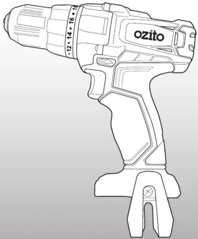
natural_image
Line drawing of a Ozito electric drill (no text or symbols on the device itself)WHAT'S IN THE BOX
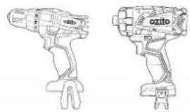
natural_image
Line drawings of two different types of electric drill motors (no text or symbols visible)Cordless Drill Driver & Impact Driver
Cordless Angle Grinder
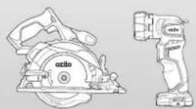
natural_image
Technical line drawing of a saw blade and a handheld tool (no text or symbols)Cordless Circular Saw & LED Torch
2.0Ah, 4.0Ah Battery & Fast Charger
PX5PAK-005
WARRANTY
IN ORDER TO MAKE A CLAIM UNDER THIS WARRANTY YOU MUST RETURN THE PRODUCT TO YOUR NEAREST BUNNINGS WAREHOUSE WITH YOUR BUNNINGS REGISTER RECEIPT. PRIOR TO RETURNING YOUR PRODUCT FOR WARRANTY PLEASE TELEPHONE OUR CUSTOMER SERVICE HELPLINE:
Australia 1800 069 486
New Zealand 0508 069 486
TO ENSURE A SPEEDY RESPONSE PLEASE HAVE THE MODEL NUMBER AND DATE OF PURCHASE AVAILABLE. A CUSTOMER SERVICE REPRESENTATIVE WILL TAKE YOUR CALL AND ANSWER ANY QUESTIONS YOU MAY HAVE RELATING TO THE WARRANTY POLICY OR PROCEDURE.
WARNING
The following actions will result in the warranty being void.
- If the tool has been operated on a supply voltage other than that specified on the tool.
- If the tool shows signs of damage or defects caused by or resulting from abuse, accidents or alterations.
- Failure to perform maintenance as set out within the instruction manual.
- If the tool is disassembled or tampered with in any way.
The benefits provided under this warranty are in addition to other rights and remedies which are available to you at law.
Our goods come with guarantees that cannot be excluded at law. You are entitled to a replacement or refund for a major failure and for compensation for any other reasonably foreseeable loss or damage. You are also entitled to have the goods repaired or replaced if the goods fail to be of acceptable quality and the failure does not amount to a major failure.
Generally you will be responsible for all costs associated with a claim under this warranty, however, where you have suffered any additional direct loss as a result of a defective product you may be able to claim such expenses by contacting our customer service helpline above.
5 YEAR REPLACEMENT WARRANTY
Your Product is guaranteed for a period of 60 months from the original date of purchase and is intended for DIY (Do It Yourself) use only. If a product is defective it will be replaced in accordance with the terms of this warranty. Lithium Ion batteries and chargers are covered by a 36 month warranty and are excluded from the warranty extension. Warranty excludes consumable parts.
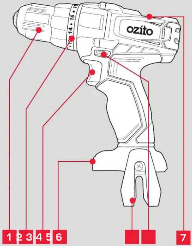
KNOW YOUR PRODUCT SETUP & PRE
CORDLESS DRILL DRIVER (PXDDS-201)
1 Keyless Chuck
5 Belt Clip
2 Torque Adjustment Collar
6 Forward/ Reverse Lever
3 Variable Speed Trigger
7 Gearbox speed selector
4 Battery Seating
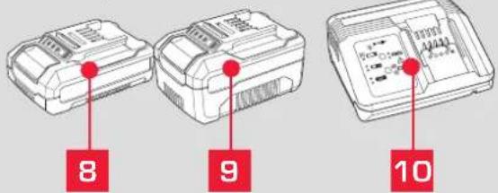
BATTERY & CHARGER
8 2.0Ah Battery
10 Fast Charger
9 4.0Ah Battery
ONLINE MANUAL
Scan this QR Code with your mobile device to take you to the online manual.

ARATION
1. BATTERY & CHARGING

CAUTION: THE CHARGER FOR THIS PRODUCT SHOULD BE PROTECTED BY A RESIDUAL CURRENT DEVICE (RATED AT 30MA OR LESS).
The purchased battery will be shipped in a low charge condition, and requires charging prior to use. Allow several cycles of charging and discharging (through use of the tool) for the battery to reach its optimum performance / runtime.
Charging your lithium ion battery - Fast Charger
1 Connect the charger into a mains power outlet.
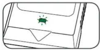
2 The charger LED will flash green showing power is being supplied to the charger.
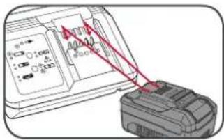
3 With the charger sitting on a flat surface, align the raised ribs on the battery with the recess in the charger and slide onto the charger ensuring a firm connection.
4 The charger LED will illuminate red signifying that the battery is charging.
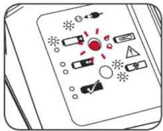
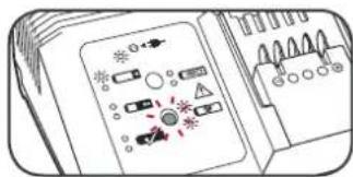
5 The charger LED will illuminate green once the battery is fully charged.
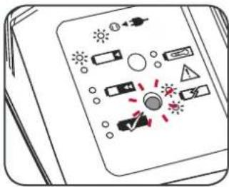
Charger LED Indicator
| LED Indicator Situation | |
| GREEN (Flashing) Stand By (no battery pack is inserted) | |
| RED (Flashing) Battery is charging (low charge) | |
| RED (Illuminated) Battery is charging (mid charge) | |
| GREEN (Illuminated) Battery is fully charged | |
| BOTH(Illuminated) Battery pack is too hot or too cold (charging will begin automatically when battery reaches correct charging temperature). | |
| BOTH (Flashing) Defective battery. Never charge a defective battery pack!Remove battery pack from charger. |
Charging your lithium ion battery - Eco Charger
1 Connect the charger into a mains power outlet.
2 The charger LED will flash green showing power is being supplied to the charger.
natural_image
Simple line drawing of a device with a green insect-like symbol on the cover (no text or labels)3 With the battery sitting on a flat surface, align the raised ribs on the battery with the recess in the charger and slide onto the battery ensuring a firm connection.
natural_image
Line drawing of a hand holding a device with red arrows indicating direction (no text or symbols)4 The charger LED will illuminate red signifying that the battery is charging.
5 When removing the charger from the battery, first press the battery release tab, then slide the charger from its position.
natural_image
Illustration of hands using a handheld device to interact with a screen (no text or symbols visible)| Charger LED Indicator | |
| LED Indicator Situation | |
| GREEN (Flashing) Stand By (no battery pack is inserted) | |
| RED (Illuminated) Battery is charging (low charge) | |
| GREEN (Illuminated) Battery is fully charged | |
| RED (Flashing) Battery or Charger fault | |
| RED & GREEN (Flashing) Battery pack is too hot or too cold (remove battery from charger and store at room temperature 20°C. Insert battery again when at correct charging temperature). If this happens again, the battery is defective and needs to be replaced. |
Battery Charge Indicator
The purchased battery is equipped with a battery charge indicator to show the state of the battery charge.
Press the charge indicator button and look to see which LED lights.
natural_image
Diagram of a mechanical component with a red arrow indicating a specific feature (no text or symbols present)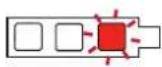
Battery requires
immediate charging
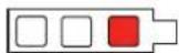
Low state of charge, requires charging soon.
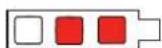
Mid state of charge
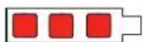
Full state of charge.
Note: The battery needs to be removed from the tool to check the state of charge.
2. BATTERY INSTALLATION
Installing the Battery Pack
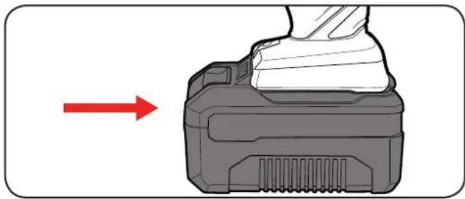
1 Slide the battery into the drill base until it clicks into place.
natural_image
Diagram showing a mechanical component with a red arrow pointing to it, no text or symbols presentRemoving the Battery Pack
1 Hold down the battery release button.
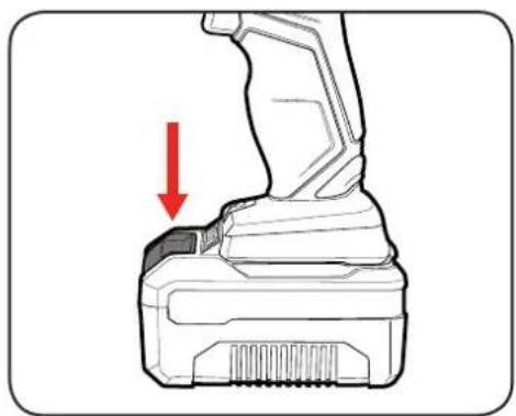
natural_image
Technical line drawing of a mechanical device with a red arrow indicating downward motion (no text or symbols)2 Slide the battery out.
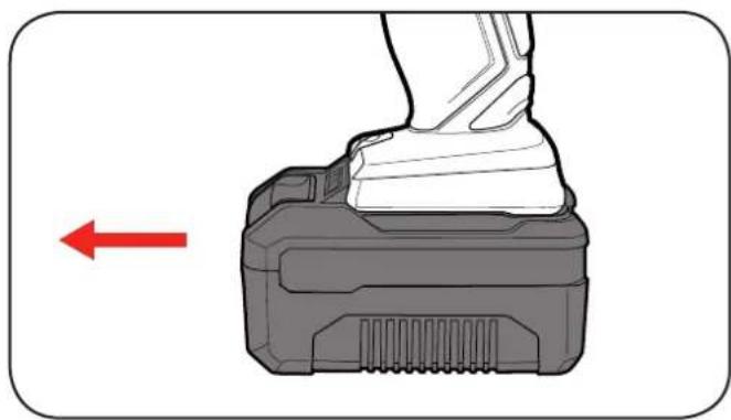
natural_image
Diagram of a mechanical component with a red arrow indicating direction (no text or symbols present)3. KEYLESS CHUCK 4. CONTROLS
WARNING! Ensure the tool is turned off & disconnected from the power supply before performing any of the following operations.
Installing a Drill Bit
1 Rotate the chuck collar anti-clockwise to open the chuck
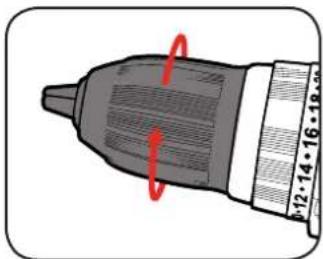
natural_image
Illustration of a drill bit with red motion arrows indicating rotational direction (no text or symbols)2 Insert the drill bit, making sure it is centred in the chuck.
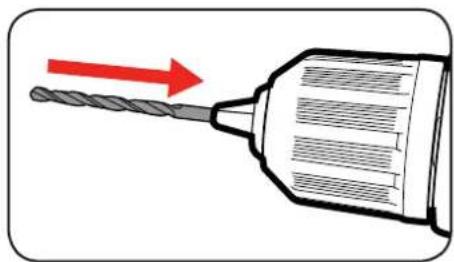
natural_image
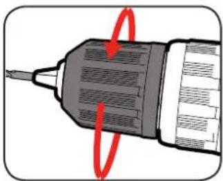
Illustration of a drill bit with a red arrow indicating direction (no text or symbols)3 Tighten the chuck by turning clockwise.
natural_image
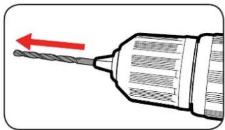
Illustration of a screwdriver with red motion arrows indicating rotation (no text or symbols)4 Pull on the bit to ensure it is firmly secured.
natural_image
Illustration of a drill bit with a red arrow indicating direction (no text or symbols)Removing a Drill Bit
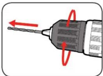
1 Open the chuck by rotating the chuck collar and remove the frill bit.
natural_image
Illustration of a drill bit with red motion arrows indicating tool movement (no text or symbols)
CAUTION: TO REDUCE THE RISK OF INJURY WE RECOMMEND THE USE OF GLOVES WHEN HANDLING DRILL BITS.
Forward/ Reverse Lever
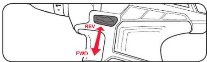
1 For forward rotation, push the fwd/rev lever towards the left side of the drill. For reverse rotation push fwd/rev lever to the right.
Variable Speed Trigger
1 To start drilling squeeze the variable speed trigger.
2 To stop drilling release the trigger.
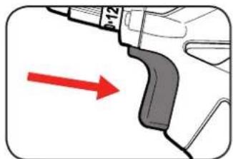
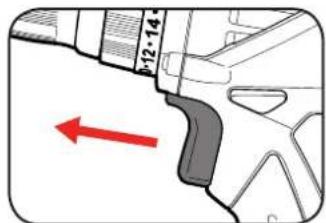
Note: The more the variable speed trigger is depressed, the faster the drill bit will rotate.
Adjusting Torque
1 Rotate the torque collar to the desired setting.
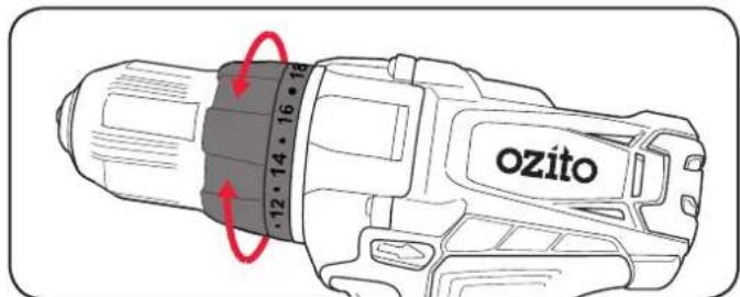
Note: Selecting a higher torque setting will allow the drill to use more torque to drive the screw in or out. To prevent damaging the screw head, it is recommended to start at a low torque setting and increase when necessary.
Speed Control
The gear selector controls the speed of the drill. First gear allows slower drilling with more torque, while second gear is suitable when less torque but higher speed is required.
-
Slide the switch forward to select first gear.
-
Slide the switch backward to select second gear.
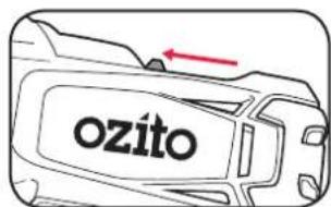
5. DRILLING
Before starting to drill, perform a few simple checks.
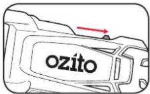
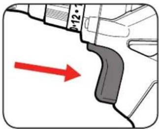
1 Depress and release the variable speed trigger to ensure it is not locked on.
2 Check the forward/reverse lever is on desired setting.
natural_image
Diagram of a mechanical component with a red arrow indicating direction (no text or symbols present)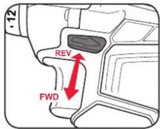
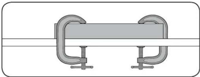
3 Secure the material to be drilled in a vice or clamp to stop it turning whilst drilling.
natural_image
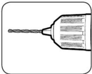
Diagram of a mechanical clamp or bracket with two curved arms and a central horizontal bar (no text or symbols)4 Hold the drill firmly and place the bit at the point to be drilled.
5 Depress the variable speed trigger to start the drill.
natural_image
Line drawing of a drill bit with a spiral head and handle (no text or symbols)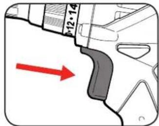
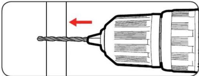
6 Move the drill bit into the workpiece.
natural_image
Diagram of a drill bit with a red arrow indicating direction (no text or symbols)Note: Do not force the drill or apply side pressure to elongate the hole. Let the drill do all the work.
6. HELPFUL TIPS
Drilling to a Preset Depth
A simple way of achieving a hole at a desired depth is to use masking tape.
1 Measure along the drill bit to indicate the desired depth
2 Wrap a small piece of masking tape tightly around the drill bit.
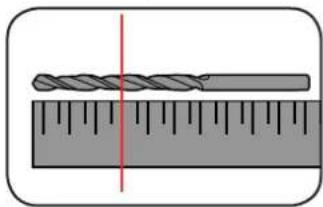
natural_image
Diagram of a twist drill bit placed on a ruler, showing measurement alignment (no text or symbols)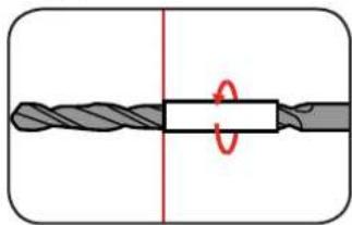
natural_image
Diagram of a twist drill bit with a central bar and red circular motion indicator (no text or symbols)3 Drill into the material until the surface reaches the start of the tape.
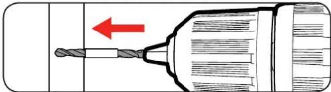
natural_image
Diagram of a drill bit with a red arrow indicating direction, no text or symbols presentTorque Settings
Torque settings can alter the depth to which you can drill or drive into a surface. To determine the torque setting required to drive a screw perfectly flush to the work surface, follow the below steps.
1 Set the torque collar to lowest setting and tighten the first screw.
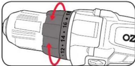
2 If the clutch rachets and makes a clicking sound before screw is flush, increase the collar setting and continue tightening.
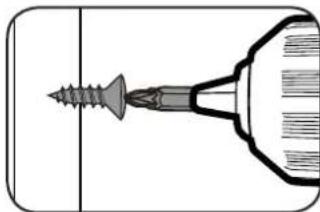
natural_image
Diagram of a screwdriver inserted into a cylindrical component (no text or symbols)3 Repeat until you reach the correct setting/ screw depth. Use this setting for the remaining screws.
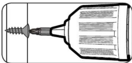
natural_image
Technical line drawing of a screwdriver with threaded tip and pointed tip (no text or symbols)When drilling hard, smooth surfaces, use a centre punch to mark the desired hole location. This measure will prevent the drill bit from slipping off centre as you start the hole.
When drilling metals, use light oil on the drill bit to keep it from overheating. The oil will prolong the life of the bit and increase drilling action.
MAINTENANCE
- When not in use, the drill should be stored in a dry, frost free location, keep out of children's reach.
- Keep ventilation slots of the drill clean at all times and prevent anything from entering.
- If the housing of the drill requires cleaning, do not use solvents. Use of a cloth only is recommended.
- Blow out the ventilation slots with compressed air periodically.
Note: Ozito Industries will not be responsible for any damage or injuries caused by repair of the drill by an unauthorised person or by mishandling.
Battery protection system
The tool is equipped with the battery protection system, which helps to ensure a long service life.
The output power automatically cuts off during operation when the tool and/or battery are placed under the following situations:
- When the tool is overloaded:
If this occurs, release the trigger switch and remove causes of overload, then pull the switch trigger again to restart.
- When the remaining battery capacity becomes low:
Recharge the battery pack.
Note: The battery protection system does not in any way damage the tool.
Note: The indicated capacity may be lower than the actual level during use or immediately after using the tool.
TROUBLESHOOTING
LED lights do not illuminate on charger
Check the charging adaptor is securely plugged into the wall outlet.
Check the battery is firmly connected to the charging cradle.
Check that the charging jack is securely connected to the charging cradle.
The battery has a short run time
Ensure the battery is properly charged. It will take 4-5 charging cycles before the battery reaches optimum charge and run time.
Variable speed trigger is locked
Ensure that the forward / reverse lever is in the correct position; pressed left for forwards direction, pressed right for backwards direction. If it is in between the two settings the variable speed trigger will be locked.
The drill is stripping the screw head
Ensure you are starting with a low torque setting and holding the drill securely onto the screw head. Increase the torque setting as required.
Drill has cut out during use
The battery charge could be completely depleted. Place the battery on the charging cradle for 3-5 hours.
Sparking visible through the housing air vents
A small amount of sparking may be visible through the housing vents. This is normal and does not indicate a problem.
SPARE PARTS
Spare parts can be ordered from the Special Orders Desk at your local Bunnings Warehouse.
For further information, or any parts not listed here, visit www.ozito.com.au or contact Ozito Customer
Service:
Australia 1800 069 486
New Zealand 0508 069 486
E-mail: enquiries@ozito.com.au
CARING FOR THE ENVIRONMENT

Power tools that are no longer usable should not be disposed of with household waste but in an environmentally friendly way. Please recycle where facilities exist. Check with your local council authority for recycling advice.

Recycling packaging reduces the need for landfill and raw materials. Reuse of recycled material decreases pollution in the environment. Please recycle packaging where facilities exist. Check with your local council authority for recycling advice.
BATTERY AND CHARGER SAFETY WARNINGS

THIS MANUAL CONTAINS IMPORTANT SAFETY AND OPERATING INSTRUCTIONS FOR YOUR BATTERY CHARGER.
- Before using the charger read all instructions and cautionary markings on the charger, battery pack and the product using the battery pack.
- This charger is not intended for any uses other than charging rechargeable batteries. Any other use may result in risk of fire, electric shock or electrocution.
- Do not place any object on top of the charger or place the charger on a soft surface that may result in excessive internal heat. Place the charger in a position away from any heat source.
- To reduce risk of damage to the electric plug and cord, pull by the plug rather than the cord when disconnecting the charger.
- Make sure the cord is located so that it will not be stepped on, tripped over, or otherwise subjected to damage or stress.
-
An extension cord should not be used unless absolutely necessary. Use of an improper extension cord could result in the risk of fire, electric shock or electrocution.
-
Do not operate the charger if it has received a sharp blow, been dropped or otherwise damaged in any way. Have it checked by an electrician or power tool repairer.
-
Do not disassemble charger. Take it to an electrician or power tool repairer when service or repair is required. Incorrect reassembly may result in a risk of electric shock, electrocution or fire.
-
To reduce risk of electric shock, unplug the charger from the outlet before attempting any cleaning. Removing the battery pack will not reduce this risk.
-
Never attempt to connect 2 chargers together.
-
DO NOT store or use the tool and battery pack in locations where the temperature may reach or exceed 40°C (such as inside sheds or metal buildings in summer).
-
The charger is designed to operate on standard household electrical power (240 volts). Do not attempt to use it on any other voltage!
-
The battery pack is not fully charged out of the carton. First read the safety instructions and then follow the charging notes and procedures.
-
The longest life and best performance can be obtained if the battery pack is charged when the air temperature is between 18 - 24°C. Do not charge the battery pack in an air temperature below 10°C or above 40°C. This is important and will prevent damage to the battery pack.
-
Do not incinerate the battery pack even if it is seriously damaged or is completely worn out. The battery can explode in a fire.
-
Never attempt to open the battery pack for any reason. If the plastic housing of the battery pack breaks or cracks, immediately discontinue use and do not recharge.
-
During charging, the battery must be placed in a well ventilated area.
DESCRIPTION OF SYMBOLS
| V | Volts | Hz | Hertz | |
| ac/~ | Alternating current | W | Watts | |
| dc/— | Direct current | ∅ | Diameter | |
| mA | Milliamperes | Ah | Amp hour | |
| Nm | Newton Meters | No | No load speed | |
| /min | Revolutions or reciprocation per minute | |||
 | Regulatory Compliance Mark (RCM) |  [6AK5] [6AK5] | Transformer Energy Rating (MEPS) | |
| [ZBA3] | Warning | [2Y42] | Read instruction manual | |
 | Double insulated |  | Indoor use only | |
 | Thermal cut-out protection | [0X2T] | Polarity | |
 Li-ion Li-ion | Lithium Ion battery |   | Do not use or store battery in temperatures exceeding 50°C | |
[X2Z7][6O7] | Recycle battery Do not put |  | nubbish | |
 | Do not incinerate Do not g | [V0CD] | tery wet | |


ELECTRICAL SAFETY

WARNING! When using mains-powered tools, basic safety precautions, including the following, should always be followed to reduce risk of fire, electric shock, personal injury and material damage.
Read the whole manual carefully and make sure you know how to switch the tool off in an emergency, before operating the tool. Save these instructions and other documents supplied with this tool for future reference.
The charger has been designed for 230V and 240V only. Always check that the power supply corresponds to the voltage on the rating plate
Note: The supply of 230V and 240V on Ozito tools are interchangeable for Australia and New Zealand.

This tools charger is double insulated; therefore no earth wire is required.
If the supply cord is damaged, it must be replaced by an electrician or a power tool repairer in order to avoid a hazard.
Note: Double insulation does not take the place of normal safety precautions when operating this tool. The insulation system is for added protection against injury resulting from a possible electrical insulation failure within the tool.
The power supply for this products charger should be protected by a residual current device (rated at 30mA
or less). A residual current device reduces the risk of electric shock.

GENERAL POWER TOOL SAFETY WARNINGS

WARNING! Read all safety warnings and all instructions. Failure to follow the warnings and instructions may result in electric shock, fire and/or serious injury.
Save all warnings and instructions for future reference. The term "power tool" in the
warnings refers to your mains-operated (corded) power tool or battery-operated (cordless) power tool.
- Work area safety
a. Keep work area clean and well lit. Cluttered or dark areas invite accidents.
b Do not operate power tools in explosive atmospheres, such as in the presence of flammable liquids, gases or dust. Power tools create sparks which may ignite the dust or fumes.
c. Keep children and bystanders away while operating a power tool. Distractions can cause you to lose control
- Electrical safety
Power tool plugs must match the outlet. Never modify the plug in any way. Do not use any adapter plugs with earthed (grounded) power tools. Unmodified plugs and matching outlets will reduce risk of electric shock.
b: Avoid body contact with earthed or grounded surfaces, such as pipes, radiators, ranges and refrigerators. There is an increased risk of electric shock if your body is earthed or grounded.
c. Do not expose power tools to rain or wet conditions. Water entering a power tool will increase the risk of electric shock
Do not abuse the cord. Never use the cord for carrying, pulling or unplugging the power tool. Keep cord away from heat, oil, sharp edges or moving parts. Damaged or entangled cords increase the risk of electric shock.
When operating a power tool outdoors, use an extension cord suitable for outdoor use. Use of a cord suitable for outdoor use reduces the risk of electric shock.
-
If operating a power tool in a damp location is unavoidable, use a residual current device (RCD) protected supply. Use of an RCD reduces the risk of electric shock.
-
Personal safety
Stay alert, watch what you are doing and use common sense when operating a power tool. Do not use a power tool while you are tired or under the influence of drugs, alcohol or medication. A moment of inattention while operating power tools may result in serious personal injury.
b. Use personal protective equipment. Always wear eye protection. Protective equipment such as dust mask, non-skid safety shoes, hard hat, or hearing protection used for appropriate conditions will reduce personal injuries.
c. Prevent unintentional starting. Ensure the switch is in the off-position before connecting to power source and/or battery pack, picking up or carrying the tool. Carrying power tools with your finger on the switch or energising power tools that have the switch on invites accidents.
- Remove any adjusting key or wrench before turning the power tool on. A wrench or a key left attached to a rotating part of the power tool may result in personal injury.
e Do not overreach. Keep proper footing and balance at all times. This enables better control of the
power tool in unexpected situations.
Dress properly. Do not wear loose clothing or jewellery. Keep your hair, clothing and gloves away from moving parts. Loose clothes, jewellery or long hair can be caught in moving parts.
g. If devices are provided for the connection of dust extraction and collection facilities, ensure these are connected and properly used. Use of dust collection can reduce dust-related hazards.
- Power tool use and care
a. Do not force the power tool. Use the correct power tool for your application. The correct power tool will do the job better and safer at the rate for which it was designed.
b. Do not use the power tool if the switch does not turn it on and off. Any power tool that cannot be controlled with the switch is dangerous and must be repaired.
c. Disconnect the plug from the power source and/or the battery pack from the power tool before making any adjustments, changing accessories, or storing power tools. Such preventive safety measures reduce the risk of starting the power tool accidentally.
d. Store idle power tools out of the reach of children and do not allow persons unfamiliar with the power tool or these instructions to operate the power tool. Power tools are dangerous in the hands of untrained users.
c. Maintain power tools. Check for misalignment or binding of moving parts, breakage of parts and any other condition that may affect the power tool's operation. If damaged, have the power tool repaired before use. Many accidents are caused by poorly maintained power tools.
Keep cutting tools sharp and clean. Properly maintained cutting tools with sharp cutting edges are less likely to bind and are easier to control.
g. Use the power tool, accessories and tool bits etc. in accordance with these instructions, taking into account the working conditions and the work to be performed. Use of the power tool for operations different from those intended could result in a hazardous situation.
- Battery tool use and care
a. Recharge only with the charger specified by the manufacturer. A charger that is suitable for one type of battery pack may create a risk of fire when used with another battery pack.
b. Use power tools only with specifically designated battery packs. Use of any other battery packs may create a risk of injury and fire.
c. When battery pack is not in use, keep it away from other metal objects, like paper clips, coins, keys, nails, screws or other small metal objects, that can make a connection from one terminal to another. Shorting the battery terminals together may cause bums or a fire.
d. Under abusive conditions, liquid may be ejected from the battery; avoid contact. If contact accidentally occurs, flush with water. If liquid contacts eyes, additionally seek medical help. Liquid ejected from the battery may cause irritation or burns.
- Service
a. Have your power tool serviced by a qualified repair person using only identical replacement parts. This will ensure that the safety of the power tool is maintained.

DRILL DRIVER SAFETY WARNINGS

WARNING! Wear ear protectors when drilling Exposure to noise can cause
hearing loss.
Use auxiliary handle(s), if supplied with the tool. Loss of control can cause personal injury.
Hold power tool by insulated gripping surfaces, when performing an operation where the cutting accessory may contact hidden wiring or its own cord. Cutting accessory contacting a "live" wire may make exposed metal parts of the power tool "live" and could give the operator an electric shock.
Before drilling into walls, ceilings etc, ensure that there are no concealed power cables or pipes in the cavity.

WARNING! Some dust created by power sanding, sawing, grinding, g and other construction activities contain chemicals known to cause r, birth defects or other reproductive harm. Some examples of theseicals are:
- Lead from lead-based paints
- Crystalline silica from bricks and cement and other masonry products
- Arsenic and chromium from chemically treated timber
Your risk from exposure to these chemicals varies, depending on how often you do this type of work. To reduce your exposure to these chemicals: work in a well ventilated area and work with approved safety equipment, such as dust masks that are specially designed to filter out microscopic particles.
This appliance is not intended for use by young or infirm persons unless supervised by a responsible person to ensure that they can use the appliance safely. Young children should be supervised to ensure that they do not play with the appliance.

18V LITHIUM ION
CORDLESS IMPACT DRIVER
INSTRUCTION MANUAL
SPECIFICATIONS
Voltage: 18V
No Load Speed: 0-2300/min
Chuck Size: 6.35mm (1/4") Hex
Impact Rate: 0-2900/min
Max. Torque: 150Nm
Charge Time: 40mins (2.0Ah)
80mins (4.0Ah)
Weight: 1.4kg
ozito.com.au
5 YEAR REPLACEMENT WARRANTY
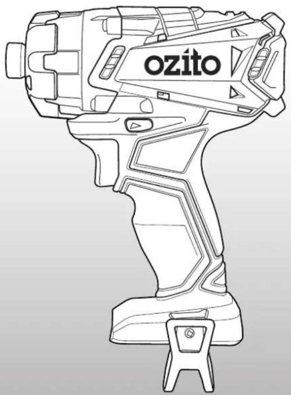
natural_image
Line drawing of a cylindrical device labeled 'ozito' with no additional text or symbolsWHAT'S IN THE BOX
natural_image
Line drawings of two different types of OZito electric drill motors (no text or symbols present)Cordless Drill Driver
& Impact Driver
Cordless Angle Grinder
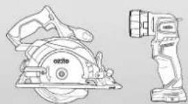
natural_image
Technical line drawing of a saw blade and camera assembly (no text or symbols)Cordless Circular Saw & LED Torch
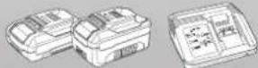
2.0Ah, 4.0Ah Battery & Fast Charger
PX5PAK-005
WARRANTY
IN ORDER TO MAKE A CLAIM UNDER THIS WARRANTY YOU MUST RETURN THE PRODUCT TO YOUR NEAREST BUNNINGS WAREHOUSE WITH YOUR BUNNINGS REGISTER RECEIPT. PRIOR TO RETURNING YOUR PRODUCT FOR WARRANTY PLEASE TELEPHONE OUR CUSTOMER SERVICE HELPLINE:
Australia 1800 069 486
New Zealand 0508 069 486
TO ENSURE A SPEEDY RESPONSE PLEASE HAVE THE MODEL NUMBER AND DATE OF PURCHASE AVAILABLE. A CUSTOMER SERVICE REPRESENTATIVE WILL TAKE YOUR CALL AND ANSWER ANY QUESTIONS YOU MAY HAVE RELATING TO THE WARRANTY POLICY OR PROCEDURE.
WARNING
The following actions will result in the warranty being void.
- If the tool has been operated on a supply voltage other than that specified on the tool.
- If the tool shows signs of damage or defects caused by or resulting from abuse, accidents or alterations.
- Failure to perform maintenance as set out within the instruction manual.
- If the tool is disassembled or tampered with in any way.
The benefits provided under this warranty are in addition to other rights and remedies which are available to you at law.
Our goods come with guarantees that cannot be excluded at law. You are entitled to a replacement or refund for a major failure and for compensation for any other reasonably foreseeable loss or damage. You are also entitled to have the goods repaired or replaced if the goods fail to be of acceptable quality and the failure does not amount to a major failure.
Generally you will be responsible for all costs associated with a claim under this warranty, however, where you have suffered any additional direct loss as a result of a defective product you may be able to claim such expenses by contacting our customer service helpline above.
5 YEAR REPLACEMENT WARRANTY
Your Product is guaranteed for a period of 60 months from the original date of purchase and is intended for DIY (Do It Yourself) use only. If a product is defective it will be replaced in accordance with the terms of this warranty. Lithium Ion batteries and chargers are covered by a 36 month warranty and are excluded from the warranty extension. Warranty excludes consumable parts.
KNOW YOUR PRODUCT SETUP & PRE
CORDLESS IMPACT DRIVER (PXIDS-300)
1 Drive Bit Retaining Ring
4 Belt Hook
2 Tri-Beam LED Light
5 Forward/ Reverse Lever
3 Variable Speed Trigger
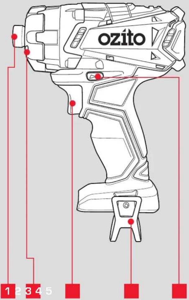
BATTERY & CHARGER
6 2.0Ah Battery
8 Fast Charger
7 4.0Ah Battery
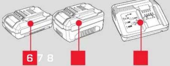
ONLINE MANUAL
Scan this OR Code with your mobile device to take you to the online manual.

RATION
1. ASSEMBLY

WARNING! ENSURE THE TOOL IS SWITCHED OFF AND THE BATTERY IS REMOVED BEFORE PERFORMING ANY OF THE FOLLOWING TASKS.
Inserting & Removing Accessories
1 Pull the drive retaining ring forward.
2 Insert the hex shank of the appropriate (1/4") driver bit.
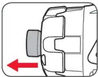
natural_image
Diagram of a mechanical component with a red arrow indicating direction (no text or symbols)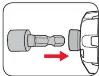
natural_image
Diagram of a screwdriver inserted into a mechanical component with a red arrow indicating direction (no text or symbols)3 Release the drive bit retaining ring then pull on the bit to ensure it is firmly in place.
4 To remove, pull the drive retaining ring forward & remove the driving bit.
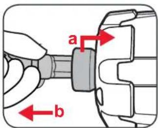
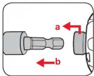

CAUTION: DO NOT HANDLE ACCESSORIES WITHOUT GLOVES AS THEY ARE SHARP AND CAN BECOME HOT AFTER USE, POTENTIALLY CAUSING PERSONAL INJURY.
Inserting & Removing the Battery
1 Align the ribs of the battery with the recess at the base of the driver hanlde and push in until it clicks into place.
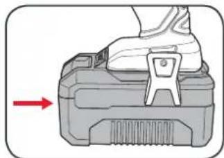
natural_image
Illustration of a mechanical device with a foot pressing a button, showing a red arrow indicating direction (no text or symbols present)2 To remove, press and hold the battery release tab and then slide out.
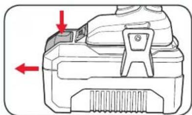
natural_image
Technical diagram of a mechanical component with red arrows indicating direction (no text or symbols)2. BATTERY & CHARGING

CAUTION: THE CHARGER FOR THIS PRODUCT SHOULD BE PROTECTED BY A RESIDUAL CURRENT DEVICE (RATED AT 30MA OR LESS).
Charging your lithium ion battery - Fast Charger
1 Connect the charger into a mains power outlet.
2 The charger LED will flash green showing power is being supplied to the charger.
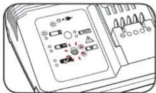
3 With the charger sitting on a flat surface, align the raised ribs on the battery with the recess in the charger and slide onto the charger ensuring a firm connection.
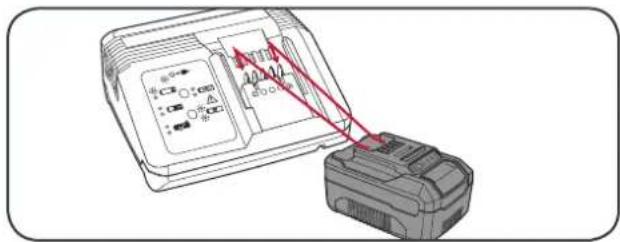
4 The charger LED will illuminate red signifying that the battery is charging.
5 The charger LED will illuminate green once the battery is fully charged.
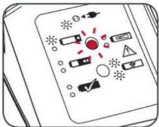
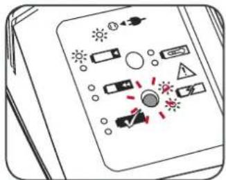
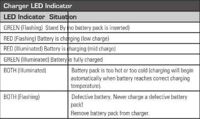 |
Charging your lithium ion battery - Eco Charger
1 Connect the charger into a mains power outlet.
2 The charger LED will flash green showing power is being supplied to the charger.
3 With the battery sitting on a flat surface, align the raised ribs on the battery with the recess in the charger and slide onto the battery ensuring a firm connection.
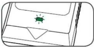
natural_image
Simple line drawing of a device casing with a green insect on top (no text or symbols)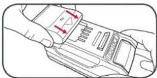
natural_image
Line drawing of a hand holding a device with red arrows indicating movement or force (no text or symbols)4 The charger LED will illuminate red signifying that the battery is charging.
5 When removing the charger from the battery, first press the battery release tab, then slide the charger from its position.
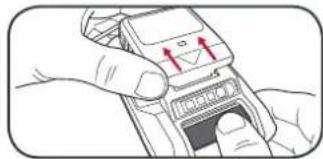
natural_image
Illustration of hands holding a mobile phone with a red arrow pointing to the screen (no text or symbols visible)| Charger LED Indicator | |
| LED Indicator Situation | |
| GREEN (Flashing) Stand By (no battery pack is inserted) | |
| RED (Illuminated) Battery is charging (low charge) | |
| GREEN (Illuminated) Battery is fully charged | |
| RED (Flashing) Battery or Charger fault | |
| RED & GREEN (Flashing) Battery pack is too hot or too cold (remove battery from charger and store at room temperature 20°C. Insert battery again when at correct charging temperature). If this happens again, the battery is defective and needs to be replaced. |
Battery Charge Indicator
The purchased battery is equipped with a battery charge indicator to show the state of the battery charge.
Press the charge indicator button and look to see which LED lights.
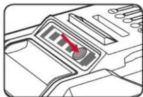
natural_image
Diagram of a mechanical device with a red arrow pointing to a control panel (no text or symbols visible)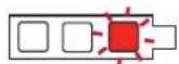
Battery requires immediate charging
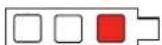
Low state of charge, requires charging soon.
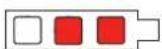
Mid state of charge
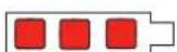
Full state of charge.
Note: The battery needs to be removed from the tool to check the state of charge.
3. CONTROLS
Variable Speed Trigger
1 To start the driver, squeeze the variable speed trigger.
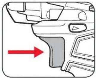
natural_image
Diagram of a car's front and side components with a red arrow indicating direction (no text or symbols)3 Control the speed by adjusting the amount of pressure applied to the trigger.
2 Release the variable speed trigger to stop the driver.
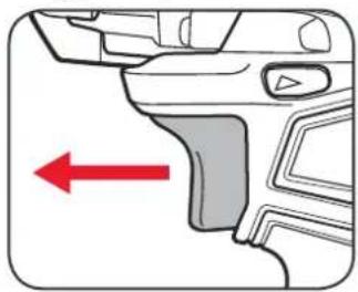
natural_image
Diagram of a car's front and side panels with a red arrow indicating left side (no text or symbols present)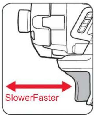
Forward/Reverse Lever
1 To drive screws and bolts, push the fwd/rev lever hard left.
2 To remove screws and bolts, push the fwd/rev lever hard right.
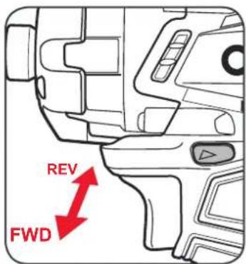
4. DRIVING PROCEDURE
1 Depress and release the on/off trigger to ensure it is not locked.
2 Check the forward/reverse lever is on desired setting.
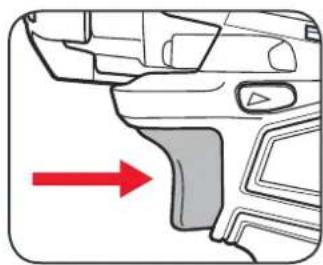
natural_image
Diagram of a car's front and side components with a red arrow pointing to the nose area (no text or symbols present)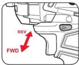
3 Ensure the work piece is secured to stop it turning whilst driving.
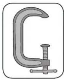
natural_image
Illustration of a C-shaped mechanical clamp with a bolted joint (no text or symbols)4 Hold the driver firmly against the fastner to stop it slipping.
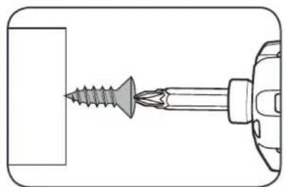
natural_image
Diagram of a screwdriver inserted into a rectangular block, showing tip and base (no text or symbols)5 Lightly squeeze the variable speed trigger to start the driver.
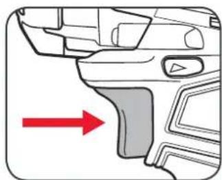
natural_image
Diagram of a car's front and side components with a red arrow indicating direction (no text or symbols)6 Slowly increase pressure on trigger to appropriate torque for circumstances until screw or bolt is tightened.
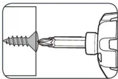
natural_image
Technical line drawing of a screwdriver inserted into a housing (no text or symbols)Note: Do not force the driver or apply side pressure to elongate the hole. Let the impact driver do the work.
TROUBLESHOOTING
LED lights do not illuminate on charger
Check the charging adaptor is securely plugged into the wall out let.
Check the battery is firmly connected to the charging cradle.
Check that the charging jack is securely connected to the charging cradle.
The battery has a short run time
Ensure the battery is properly charged. It will take 4-5 charging cycles before the battery reaches optimum charge and run time. On the initial charge, the battery requires 5 hours of charging. Subsequent charging only requires 3-5 hours.
Sparking visible through the housing vents
A small amount of sparking may be visible through the housing vents.
This is normal and does not indicate a problem.
Variable speed trigger is locked
Ensure that the forward / reverse lever is in the correct position; pressed left for forwards direction, pressed right for backwards direction. If it is in between the two settings the variable speed trigger will be locked.
The Impact Driver is stripping the screw head
Ensure you are not applying to much force to the screw. Decrease the force by using a slower trigger speed.
Battery protection system
The tool is equipped with the battery protection system, which helps to ensure a long service life.
The output power automatically cuts off during operation when the tool and/or battery are placed under the following situations:
- When the tool is overloaded:
If this occurs, release the trigger switch and remove causes of overload, then pull the switch trigger again to restart.
- When the remaining battery capacity becomes low:
Recharge the battery pack.
MAINTENANCE

WARNING! ALWAYS ENSURE THE TOOL HAS COMPLETELY STOPPED AND THE BATTERY IS REMOVED PRIOR TO ANY MAINTENANCE.
- After each use, blow air through the tool housing to ensure it is free from all dust, dirt, etc. Build up of dust, dirt particles may cause the tool to overheat and shorten the life of the tool.
- If the housing of the impact driver requires cleaning, do not use solvents but a moist soft cloth or soft brush only.
- Never let any liquid get inside the tool, never immerse any part of the tool into liquid.
- When not in use, the impact driver should be stored in a dry, frost free location not within the reach of children.
Note: Ozito Industries will not be responsible for any damage or injuries caused by the repair of the impact driver by an unauthorised person or by mishandling of the impact driver.
SPARE PARTS
Spare parts can be ordered from the Special Orders Desk at your local Bunnings Warehouse.
For further information, or any parts not listed here, visit www.ozito.com.au or contact Ozito Customer
Service:
Australia 1800 069 486
New Zealand 0508 069 486
E-mail: enquiries@ozito.com.au

BATTERY & CHARGER SAFETY WARNINGS
THIS MANUAL CONTAINS IMPORTANT SAFETY AND OPERATING INSTRUCTIONS FOR YOUR BATTERY CHARGER.
- Before using the charger read all instructions and cautionary markings on the charger, battery pack and the product using the battery pack.
- This charger is not intended for any uses other than charging rechargeable batteries. Any other use may result in risk of fire, electric shock or electrocution.
- Do not place any object on top of the charger or place the charger on a soft surface that may result in excessive internal heat. Place the charger in a position away from any heat source.
- To reduce risk of damage to the electric plug and cord, pull by the plug rather than the cord when disconnecting the charger.
- Make sure the cord is located so that it will not be stepped on, tripped over, or otherwise subjected to damage or stress.
- An extension cord should not be used unless absolutely necessary. Use of an improper extension cord could result in the risk of fire, electric shock or electrocution.
- Do not operate the charger if it has received a sharp blow, been dropped or otherwise damaged in any way. Have it checked by an electrician or power tool repairer.
- Do not disassemble charger. Take it to an electrician or power tool repairer when service or repair is required. Incorrect reassembly may result in a risk of electric shock, electrocution or fire.
- To reduce risk of electric shock, unplug the charger from the outlet before attempting any cleaning. Removing the battery pack will not reduce this risk.
- Never attempt to connect 2 chargers together.
- DO NOT store or use the tool and battery pack in locations where the temperature may reach or exceed 40°C (such as inside sheds or metal buildings in summer).
- The charger is designed to operate on standard household electrical power (240 volts). Do not attempt to use it on any other voltage!
- The battery pack is not fully charged out of the carton. First read the safety instructions and then follow the charging notes and procedures.
- The longest life and best performance can be obtained if the battery pack is charged when the air temperature is between 18 - 24°C. Do not charge the battery pack in an air temperature below 10°C or above 40°C. This is important and will prevent damage to the battery pack.
- Do not incinerate the battery pack even if it is seriously damaged or is completely worn out. The battery can explode in a fire.
- Never attempt to open the battery pack for any reason. If the plastic housing of the battery pack breaks or cracks, immediately discontinue use and do not recharge.
- During charging, the battery must be placed in a well ventilated area.
DESCRIPTION OF SYMBOLS
| V | Volts | Hz | Hertz | |
| ac/~ | Alternating current | W | Watts | |
| dc/--- | Direct current | ∅ | Diameter | |
| mA | Milliamperes | Ah | Amp hour | |
| Nm | Newton Meters | No | No load speed | |
| /min | Revolutions or reciprocation per minute | |||
| [3200] | Regulatory Compliance Mark (RCM) | IVEfficiency Level (MEPS) | Transformer Energy Rating (MEPS) | |
| [375K] | Warning | Read instruction manual | ||
 | Double insulated | Indoor use only | ||
[582A] | Thermal cut-out protection | Polarity | ||
| Lithium Ion battery | MAX.50°C | Do not use or store battery in temperatures exceeding 50°C | ||
| [22XX] | Recycle battery Do not put in the rubbish | |||
| [5XX0] | Do not incinerate Do not get battery wet | |||
CARING FOR THE ENVIRONMENT


Power tools that are no longer usable should not be disposed of with household waste but in an environmentally friendly way. Please recycle where facilities exist. Check with your local council authority for recycling advice.
Recycling packaging reduces the need for landfill and raw materials. Reuse of recycled material decreases pollution in the environment. Please recycle packaging where facilities exist. Check with your local council authority for recycling advice.

ELECTRICAL SAFETY

WARNING! When using mains-powered tools, basic safety precautions, including the following, should always be followed to reduce risk of fire, electric shock, personal injury and material damage.
Read the whole manual carefully and make sure you know how to switch the tool off in an emergency, before operating the tool. Save these instructions and other documents supplied with this tool for future reference.
The charger has been designed for 230V and 240V only. Always check that the power supply corresponds to the voltage on the rating plate.
Note: The supply of 230V and 240V on Ozito tools are interchangeable for Australia and New Zealand.

This tools charger is double insulated; therefore no earth wire is required.
If the supply cord is damaged, it must be replaced by an electrician or a power tool repairer in order to avoid a hazard.
Note: Double insulation does not take the place of normal safety precautions when operating this tool. The insulation system is for added protection against injury resulting from a possible electrical insulation failure within the tool.
The power supply for this products charger should be protected by a residual current device (rated at 30mA or less). A residual current device reduces the risk of electric shock.

GENERAL POWER TOOL SAFETY WARNINGS

WARNING! Read all safety warnings and all instructions. Failure to follow the warnings and instructions may result in electric shock, fire and/or serious injury
Save all warnings and instructions for future reference. The term "power tool" in the
warnings refers to your mains-operated (corded) power tool or battery-operated (cordless) power tool.
- Work area safety
a. Keep work area clean and well lit. Cluttered or dark areas invite accidents.
b. Do not operate power tools in explosive atmospheres, such as in the presence of flammable liquids, gases or dust. Power tools create sparks which may ignite the dust or fumes.
c. Keep children and bystanders away while operating a power tool. Distractions can cause you to lose control.
- Electrical safety
a. Power tool plugs must match the outlet. Never modify the plug in any way. Do not use any adapter plugs with earthed (grounded) power tools. Unmodified plugs and matching outlets will reduce risk of electric shock.
b. Avoid body contact with earthed or grounded surfaces, such as pipes, radiators, ranges and refrigerators. There is an increased risk of electric shock if your body is earthed or grounded.
c. Do not expose power tools to rain or wet conditions. Water entering a power tool will increase the risk of electric shock.
Do not abuse the cord. Never use the cord for carrying, pulling or unplugging the power tool. Keep cord away from heat, oil, sharp edges or moving parts. Damaged or entangled cords increase the risk of electric shock.
-
When operating a power tool outdoors, use an extension cord suitable for outdoor use. Use of a cord suitable for outdoor use reduces the risk of electric shock.
-
If operating a power tool in a damp location is unavoidable, use a residual current device (RCD) protected supply. Use of an RCD reduces the risk of electric shock.
-
Personal safety
-
Stay alert, watch what you are doing and use common sense when operating a power tool. Do not use a power tool while you are tired or under the influence of drugs, alcohol or medication. A moment of inattention while operating power tools may result in serious personal injury.
b. Use personal protective equipment. Always wear eye protection. Protective equipment such as dust mask, non-skid safety shoes, hard hat, or bearing protection used for appropriate conditions will reduce personal injuries.
c. Prevent unintentional starting. Ensure the switch is in the off-position before connecting to power source and/or battery pack, picking up or carrying the tool. Carrying power tools with your finger on the switch or energising power tools that have the switch on invites accidents.
d. Remove any adjusting key or wrench before turning the power tool on. A wrench or a key left attached to a rotating part of the power tool may result in personal injury.
e. Do not overreach. Keep proper footing and balance at all times. This enables better control of the power tool in unexpected situations
Dress properly. Do not wear loose clothing or jewellery. Keep your hair, clothing and gloves away from moving parts. Loose clothes, jewellery or long hair can be caught in moving parts.
g. If devices are provided for the connection of dust extraction and collection facilities, ensure these are connected and properly used. Use of dust collection can reduce dust-related hazards.
- Power tool use and care
a. Do not force the power tool. Use the correct power tool for your application. The correct power tool will do the job better and safer at the rate for which it was designed.
b. Do not use the power tool if the switch does not turn it on and off. Any power tool that cannot be controlled with the switch is dangerous and must be repaired.
c. Disconnect the plug from the power source and/or the battery pack from the power tool before making any adjustments, changing accessories, or storing power tools. Such preventive safety measures reduce the risk of starting the power tool accidentally.
d. Store idle power tools out of the reach of children and do not allow persons unfamiliar with the power tool or these instructions to operate the power tool. Power tools are dangerous in the hands of untrained users.
e. Maintain power tools. Check for misalignment or binding of moving parts, breakage of parts and any other condition that may affect the power tool's operation. If damaged, have the power tool repaired before use. Many accidents are caused by poorly maintained power tools.
f. Keep cutting tools sharp and clean. Properly maintained cutting tools with sharp cutting edges are less likely to bind and are easier to control.
g. Use the power tool, accessories and tool bits etc. in accordance with these instructions, taking into account the working conditions and the work to be performed. Use of the power tool for operations different from those intended could result in a hazardous situation.
- Battery tool use and care
a. Recharge only with the charger specified by the manufacturer. A charger that is suitable for one type of battery pack may create a risk of fire when used with another battery pack.
b. Use power tools only with specifically designated battery packs. Use of any other battery packs may create a risk of injury and fire.
c. When battery pack is not in use, keep it away from other metal objects, like paper clips, coins, keys, nails, screws or other small metal objects, that can make a connection from one terminal to another. Shorting the battery terminals together may cause burns or a fire.
d Under abusive conditions, liquid may be ejected from the battery; avoid contact. If contact accidentally occurs, flush with water. If liquid contacts eyes, additionally seek medical help. Liquid ejected from the battery may cause irritation or burns.
- Service
a. Have your power tool serviced by a qualified repair person using only identical replacement parts. This will ensure that the safety of the power tool is maintained.

IMPACT DRIVER SAFETY WARNINGS

WARNING! Wear ear protectors when impact drilling Exposure to noise can cause hearing loss.
Use auxiliary handle(s), if supplied with the tool. Loss of control can cause personal injury.
Hold power tool by insulated gripping surfaces, when performing an operation where the cutting accessory may contact hidden wiring or its own cord. Cutting accessory contacting a "live" wire may make exposed metal parts of the power tool "live" and could give the operator an electric shock.
Before drilling into walls, ceilings etc, ensure that there are no concealed power cables or pipes in the cavity.

WARNING! Some dust created by power sanding, sawing, grinding, drilling and other construction activities contain chemicals known to cancer, birth defects or other reproductive harm.
Some examples of these chemicals are:
- Lead from lead-based paints
- Crystalline silica from bricks and cement and other masonry products
- Arsenic and chromium from chemically treated timber
Your risk from exposure to these chemicals varies, depending on how often you do this type of work. To reduce your exposure to these chemicals: work in a well ventilated area and work with approved safety equipment, such as dust masks that are specially designed to filter out microscopic particles.

WARNING! This appliance is not intended for use by young or infirm persons unless supervised by a responsible person to ensure that they can use the appliance. Young children should be supervised to ensure that they do not play with the appliance.

18V LITHIUM ION
CORDLESS LED TORCH
INSTRUCTION MANUAL
SPECIFICATIONS
Input: 18V
Number of LEDs: 1
Cree LED 3W
Brightness: 250 Lumen
Charge Time: 40mins (2.0Ah)
80mins (4.0Ah)
Weight: 0.2kg
ozito.com.au

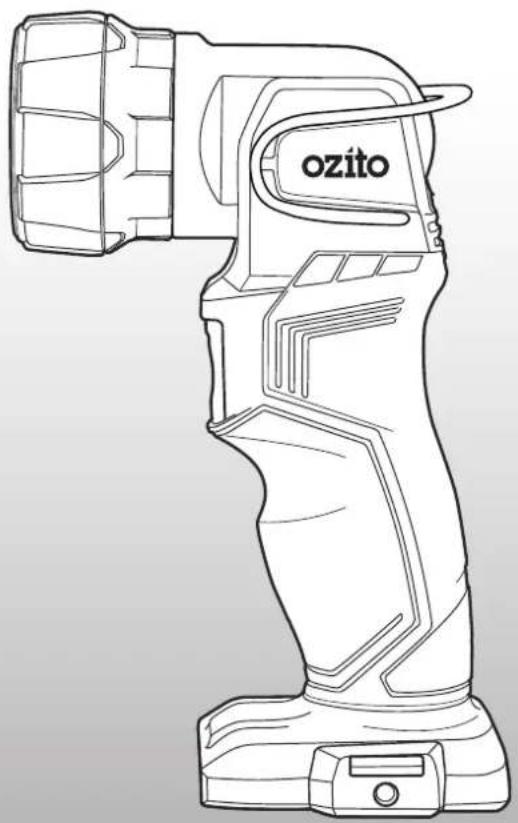
natural_image
Line drawing of a flashlight with 'ozito' branding on the handle (no additional text or symbols)WHAT'S IN THE BOX
natural_image
Line drawings of two different types of OZILIO electric drillers (no text or symbols present)Cordless Drill Driver
& Impact Driver
Cordless Angle Grinder
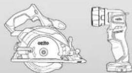
natural_image
Technical line drawing of a saw cutting machine and a mechanical component (no text or symbols)Cordless Circular Saw
& LED Torch
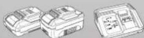
2.0Ah, 4.0Ah Battery & Fast
Charger
PX5PAK-005
WARRANTY
IN ORDER TO MAKE A CLAIM UNDER THIS WARRANTY YOU MUST RETURN THE PRODUCT TO YOUR NEAREST BUNNINGS WAREHOUSE WITH YOUR BUNNINGS REGISTER RECEIPT. PRIOR TO RETURNING YOUR PRODUCT FOR WARRANTY PLEASE TELEPHONE OUR CUSTOMER SERVICE HELPLINE:
Australia 1800 069 486
New Zealand 0508 069 486
TO ENSURE A SPEEDY RESPONSE PLEASE HAVE THE MODEL NUMBER AND DATE OF PURCHASE AVAILABLE. A CUSTOMER SERVICE REPRESENTATIVE WILL TAKE YOUR CALL AND ANSWER ANY QUESTIONS YOU MAY HAVE RELATING TO THE WARRANTY POLICY OR PROCEDURE.
WARNING
The following actions will result in the warranty being void.
- If the tool has been operated on a supply voltage other than that specified on the tool.
- If the tool shows signs of damage or defects caused by or resulting from abuse, accidents or alterations.
- Failure to perform maintenance as set out within the instruction manual.
- If the tool is disassembled or tampered with in any way.
The benefits provided under this warranty are in addition to other rights and remedies which are available to you at law.
Our goods come with guarantees that cannot be excluded at law. You are entitled to a replacement or refund for a major failure and for compensation for any other reasonably foreseeable loss or damage. You are also entitled to have the goods repaired or replaced if the goods fail to be of acceptable quality and the failure does not amount to a major failure.
Generally you will be responsible for all costs associated with a claim under this warranty, however, where you have suffered any additional direct loss as a result of a defective product you may be able to claim such expenses by contacting our customer service helpline above.
5 YEAR REPLACEMENT WARRANTY
Your Product is guaranteed for a period of 60 months from the original date of purchase and is intended for DIY (Do It Yourself) use only. If a product is defective it will be replaced in accordance with the terms of this warranty. Lithium Ion batteries and chargers are covered by a 36 month
warranty and are excluded from the warranty extension. Warranty excludes consumable parts.
KNOW YOUR PRODUCT
CORDLESS LED TORCH (PXTLS-905)
1 LED Light
4 Sure Grip Handle
2 Rotating Head
5 Battery Seating
3 On/Off Switch
6 Hanging Hook
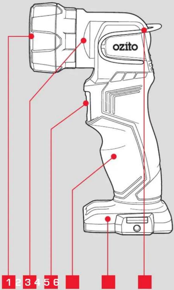
BATTERY & CHARGER
7 2.0Ah Battery
9 Fast Charger
8 4.0Ah Battery
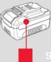
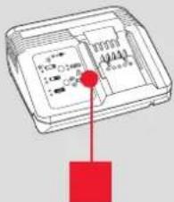
ONLINE MANUAL
Scan this QR Code with your mobile device to take you to the online manual.

SETUP & PREPARATION
1. BATTERY & CHARGING

CAUTION: THE CHARGER FOR THIS PRODUCT SHOULD BE PROTECTED BY A RESIDUAL CURRENT DEVICE (RATED AT 30mA OR LESS).
The purchased battery will be shipped in a low charge condition, and requires charging prior to use. Allow several cycles of charging and discharging (through use of the tool) for the battery to reach its optimum performance / runtime.
Charging your lithium ion battery - Fast Charger
1 Connect the charger into a mains power outlet.
2 The charger LED will flash green showing power is being supplied to the charger.
3 With the charger sitting on a flat surface, align the raised ribs on the battery with the recess in the charger and slide onto the charger ensuring a firm connection.
4 The charger LED will illuminate red signifying that the battery is charging.
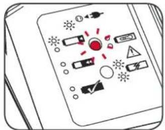
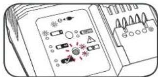
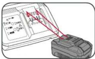
5 The charger LED will illuminate green once the battery is fully charged.

| Charger LED Indicator | |
| LED Indicator Situation | |
| GREEN (Flashing) Stand By (no battery pack is inserted) | |
| RED (Flashing) Battery is charging (low charge) | |
| RED (Illuminated) Battery is charging (mid charge) | |
| GREEN (Illuminated) Battery is fully charged | |
| BOTH(Illuminated) Battery pack is too hot or too cold (charging will begin automatically when battery reaches correct charging temperature). | |
| BOTH (Flashing) Defective battery. Never charge a defective battery pack!Remove battery pack from charger. |
Charging your lithium ion battery - Eco Charger
1 Connect the charger into a mains power outlet.
2 The charger LED will flash green showing power is being supplied to the charger.
3 With the battery sitting on a flat surface, align the raised ribs on the battery with the recess in the charger and slide onto the battery ensuring a firm connection.
4 The charger LED will illuminate red signifying that the battery is charging.
5 When removing the charger from the battery, first press the battery release tab, then slide the charger from its position.
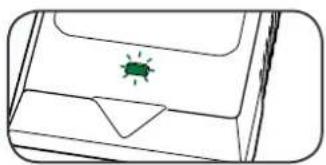
natural_image
Simple line drawing of a device with a green insect icon on the cover (no text or symbols)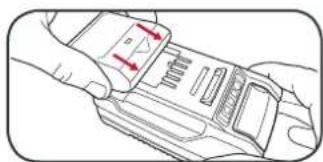
natural_image
Line drawing of a hand holding a device with red arrows indicating movement or force (no text or symbols)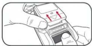
natural_image
Illustration of hands using a handheld device to interact with a screen (no text or symbols visible)Charger LED Indicator
| LED Indicator Situation | |
| GREEN (Flashing) Stand By (no battery pack is inserted) | |
| RED (Illuminated) Battery is charging (low charge) | |
| GREEN (Illuminated) Battery is fully charged | |
| RED (Flashing) Battery or Charger fault | |
| RED & GREEN (Flashing) Battery pack is too hot or too cold (remove battery from charger and store at room temperature 20°C. Insert battery again when at correct charging temperature). If this happens again, the battery is defective and needs to be replaced. |
Battery Charge Indicator
The purchased battery is equipped with a battery charge indicator to show the state of the battery charge.
Press the charge indicator button and look to see which LED lights.
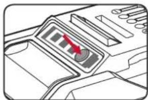
natural_image
Diagram of a printer's front panel with a red arrow pointing to the control panel (no text or symbols present)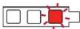
Battery requires immediate charging
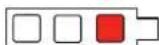
Low state of charge, requires charging soon.
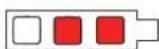
Mid state of charge
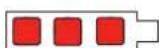
Full state of charge.
Note: The battery needs to be removed from the tool to check the state of charge.
2. FITTING THE BATTERY
Inserting & Removing the Battery
1 Align the ribs of the battery with the recess at the base of the torch and push in until it clicks into place.
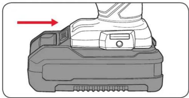
natural_image
Diagram of a mechanical device with a red arrow indicating direction, no text or symbols present2 To remove, press and hold the battery release tab and pull the battery away from torch.
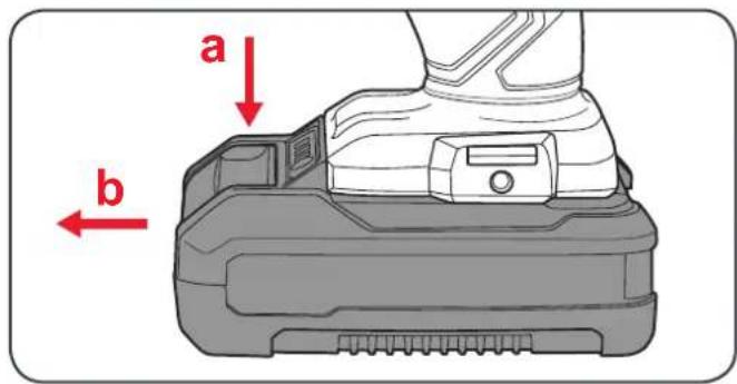
Battery protection system
The tool is equipped with the battery protection system, which helps to ensure a long service life.
The output power automatically cuts off during operation when the tool and/or battery are placed under the following situations:
- When the tool is overloaded:
If this occurs, release the trigger switch and remove causes of overload, then pull the switch trigger again to restart.
- When the remaining battery capacity becomes low:
Recharge the battery pack.
Note: The battery protection system does not in any way damage the tool.
Note: The indicated capacity may be lower than the actual level during use or immediately after using the tool.
OPERATION
3. ADJUSTING THE ANGLE 4. SWITCHING
Adjusting the Rotating Head
The torch head can be adjusted through a 90° rotation to aim the light at the desired area.
1 To aim the torch closer to the ground tilt the head forward.
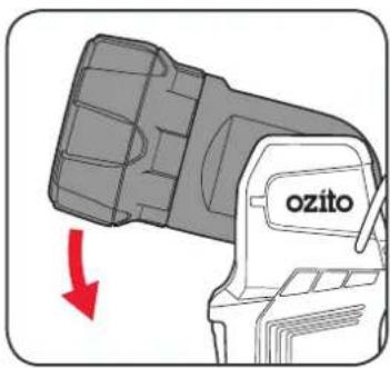
2 To aim the torch away from the ground, tilt the head backward.
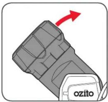
natural_image
Close-up of a gray mechanical component with a red arrow pointing to it, labeled 'ozito' (no other text or symbols)Using the hanging hook
1 To use the hanging hook at the rear of the torch, swivel metal hook to required position.
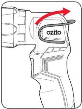
HE TORCH ON & OFF
1 To turn the torch on, press the on/off switch.
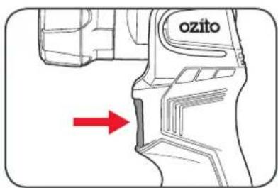
2 To turn the torch off, press the on/off switch again.
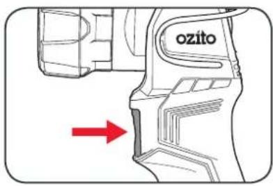
TROUBLESHOOTING
LED lights do not illuminate on charger
Check the charging adaptor is securely plugged into the wall out let.
Check the battery is firmly connected to the charging cradle.
Check that the charging jack is securely connected to the charging cradle.
The battery has a short run time
Ensure the battery is properly charged. It will take 4-5 charging cycles before the battery reaches optimum charge and run time. On the initial charge, the battery requires 5 hours of charging. Subsequent charging only requires 3-5 hours.
MAINTENANCE

WARNING! ALWAYS ENSURE THE TOOL HAS COMPLETELY STOPPED AND THE BATTERY IS REMOVED PRIOR TO ANY MAINTENANCE.
- After each use, blow air through the tool housing to ensure it is free from all dust, dirt, etc. Build up of dust, dirt particles may cause the tool to overheat and shorten the life of the tool.
- If the housing of the torch requires cleaning, do not use solvents but a moist soft cloth or soft brush only.
- Never let any liquid get inside the tool, never immerse any part of the tool into liquid.
- When not in use, the torch should be stored in a dry, frost free location not within the reach of children.
Note: Ozito Industries will not be responsible for any damage or injuries caused by the repair of the torch by an unauthorised person or by mishandling of the torch.
CARING FOR THE ENVIRONMENT
Power tools that are no longer usable should not be disposed of with household waste but in an environmentally friendly way. Please recycle where facilities exist. Check with your local council authority for recycling advice.

Recycling packaging reduces the need for landfill and raw materials. Reuse of recycled material decreases pollution in the environment. Please recycle packaging where facilities exist. Check with your local council authority for recycling advice.
DESCRIPTION OF SYMBOLS
| V | Volts | Hz | Hertz | |
| ac/~ | Alternating current | Ah | Amp hour | |
| dc/—D | rect current | No | No load speed | |
| [XW7] | Do not expose to rain. | mA | Milliamperes | |
| [DCSC] | Regulatory Compliance Mark (RCM) | IV | Transformer Energy Rating (MEPS) | |
| [XBO3] | Warning | Read instruction manual | ||
| [YCK] | Double insulated | Indoor use only | ||
| [SVC28] | Thermal cut-out protection | Polarity | ||
| [A633] | Lithium lon battery | MAX 50°C | Do not use or store battery in temperatures exceeding 50°C | |
| [ABAY] | Recycle battery Do not put in the rubbish | |||
| [AXWZ] | Do not incinerate Do not get battery wet | |||
| V | Volts | Hz | Hertz | |
| ac/~ | Alternating current | Ah | Amp hour | |
| dc/- | direct current | No | No load speed | |
| Do not expose to rain. | mA | Milliamperes | ||
| Regulatory Compliance Mark (RCM) | Transformer Energy Rating (MEPS) | |||
| Warning | Read instruction manual | |||
| Double insulated | Indoor use only | |||
| Thermal cut-out protection | Polarity | |||
| Lithium Ion battery | Do not use or store battery in temperatures exceeding 50°C | |||
| Recycle battery Do not put in the rubbish | ||||
| Do not incinerate Do not get battery wet | ||||
SPARE PARTS
Spare parts can be ordered from the Special Orders Desk at your local Bunnings Warehouse.
For further information, or any parts not listed here, visit www.ozito.com.au or contact Ozito Customer
Service:
Australia 1800 069 486
New Zealand 0508 069 486
E-mail: enquiries@ozito.com.au

ELECTRICAL SAFETY

WARNING! When using mains-powered tools, basic safety precautions, including the following, should always be followed to reduce risk of fire, electric shock, personal injury and material damage.
Read the whole manual carefully and make sure you know how to switch the tool off in an emergency, before operating the tool. Save these instructions and other documents supplied with this tool for future reference.
The charger has been designed for 230V and 240V only. Always check that the power supply corresponds to the voltage on the rating plate.
Note: The supply of 230V and 240V on Ozito tools are interchangeable for Australia and New Zealand.
If the supply cord is damaged, it must be replaced by an electrician or a power tool repairer in order to avoid a hazard.
Note: Double insulation does not take the place of normal safety precautions when operating this tool. The insulation system is for added protection against injury resulting from a possible electrical insulation failure within the tool.
Using an Extension Lead
Always use an approved extension lead suitable for the power input of this tool. Before use, inspect the extension lead for signs of damage, wear and ageing. Replace the extension lead if damaged or defective.
When using an extension lead on a reel, always unwind the lead completely. Use of an extension lead not suitable for the power input of the tool or which is damaged or defective may result in a risk of fire and electric shock.
The power supply for this products charger should be protected by a residual current device (rated at 30mA or less). A residual current device reduces the risk of electric shock.

GENERAL POWER TOOL SAFETY WARNINGS

WARNING! Read all safety warnings and all instructions. Failure to follow the warnings and instructions may result in electric shock, fire and/or serious injury.
Save all warnings and instructions for future reference. The term "power tool" in the
warnings refers to your mains-operated (corded) power tool or battery-operated (cordless) power tool.
- Work area safety
a. Keep work area clean and well lit. Cluttered or dark areas invite accidents.
b. Do not operate power tools in explosive atmospheres, such as in the presence of flammable liquids, gases or dust. Power tools create sparks which may ignite the dust or fumes.
c. Keep children and bystanders away while operating a power tool. Distractions can cause you to lose control.
- Electrical safety
a. Power tool plugs must match the outlet. Never modify the plug in any way. Do not use any adapter plugs with earthed (grounded) power tools. Unmodified plugs and matching outlets will reduce risk of electric shock.
b. Avoid body contact with earthed or grounded surfaces, such as pipes, radiators, ranges and refrigerators. There is an increased risk of electric shock if your body is earthed or grounded.
c. Do not expose power tools to rain or wet conditions. Water entering a power tool will increase the risk of electric shock.
d. Do not abuse the cord. Never use the cord for carrying, pulling or unplugging the power tool. Keep cord away from heat, oil, sharp edges or moving parts. Damaged or entangled cords increase the risk of electric shock.
c. When operating a power tool outdoors, use an extension cord suitable for outdoor use. Use of a cord suitable for outdoor use reduces the risk of electric shock.
If operating a power tool in a damp location is unavoidable, use a residual current device (RCD) protected supply. Use of an RCD reduces the risk of electric shock.
-
Personal safety
-
Stay alert, watch what you are doing and use common sense when operating a power tool. Do not use a power tool while you are tired or under the influence of drugs, alcohol or medication. A moment of inattention while operating power tools may result in serious personal injury.
b. Use personal protective equipment. Always wear eye protection. Protective equipment such as dust mask, non-skid safety shoes, hard hat, or hearing protection used for appropriate conditions will reduce personal injuries.
c. Prevent unintentional starting. Ensure the switch is in the off-position before connecting to power source and/or battery pack, picking up or carrying the tool. Carrying power tools with your finger on the switch or energising power tools that have the switch on invites accidents.
d. Remove any adjusting key or wrench before turning the power tool on. A wrench or a key left attached to a rotating part of the power tool may result in personal injury.
c. Do not overreach. Keep proper footing and balance at all times. This enables better control of the power tool in unexpected situations.
f. Dress properly. Do not wear loose clothing or jewellery. Keep your hair, clothing and gloves away from moving parts. Loose clothes, jewellery or long hair can be caught in moving parts.
g. If devices are provided for the connection of dust extraction and collection facilities, ensure these are connected and properly used. Use of dust collection can reduce dust-related hazards.
- Power tool use and care
a. Do not force the power tool. Use the correct power tool for your application. The correct power tool will do the job better and safer at the rate for which it was designed.
b. Do not use the power tool if the switch does not turn it on and off. Any power tool that cannot be controlled with the switch is dangerous and must be repaired.
c. Disconnect the plug from the power source and/or the battery pack from the power tool before making any adjustments, changing accessories, or storing power tools. Such preventive safety measures reduce the risk of starting the power tool accidentally.
d. Store idle power tools out of the reach of children and do not allow persons unfamiliar with the power tool or these instructions to operate the power tool. Power tools are dangerous in the hands of untrained users.
- Maintain power tools. Check for misalignment or binding of moving parts, breakage of parts and any other condition that may affect the power tool's operation. If damaged, have the power tool repaired before use. Many accidents are caused by poorly maintained power tools
f. Keep cutting tools sharp and clean. Properly maintained cutting tools with sharp cutting edges are less likely to bind and are easier to control.
g. Use the power tool, accessories and tool bits etc. in accordance with these instructions, taking into account the working conditions and the work to be performed. Use of the power tool for operations different from those intended could result in a hazardous situation.
- Battery tool use and care
a. Recharge only with the charger specified by the manufacturer. A charger that is suitable for one type of battery pack may create a risk of fire when used with another battery pack.
b. Use power tools only with specifically designated battery packs. Use of any other battery packs may create a risk of injury and fire.
c. When battery pack is not in use, keep it away from other metal objects, like paper clips, coins, keys, nails, screws or other small metal objects, that can make a connection from one terminal to another. Shorting the battery terminals together may cause bums or a fire.
d. Under abusive conditions, liquid may be ejected from the battery; avoid contact. If contact accidentally occurs, flush with water. If liquid contacts eyes, additionally seek medical help. Liquid ejected from the battery may cause irritation or burns.
- Service
a. Have your power tool serviced by a qualified repair person using only identical replacement parts. This will ensure that the safety of the power tool is maintained.

BATTERY AND CHARGER SAFETY WARNINGS
THIS MANUAL CONTAINS IMPORTANT SAFETY AND OPERATING INSTRUCTIONS FOR YOUR BATTERY CHARGER.
-
Before using the charger read all instructions and cautionary markings on the charger, battery pack and the product using the battery pack.
-
This charger is not intended for any uses other than charging rechargeable batteries. Any other use may result in risk of fire, electric shock or electrocution.
-
Do not place any object on top of the charger or place the charger on a soft surface that may result in excessive internal heat. Place the charger in a position away from any heat source.
-
To reduce risk of damage to the electric plug and cord, pull by the plug rather than the cord when disconnecting the charger.
-
Make sure the cord is located so that it will not be stepped on, tripped over, or otherwise subjected to damage or stress.
-
An extension cord should not be used unless absolutely necessary. Use of an improper extension cord could result in the risk of fire, electric shock or electrocution.
-
Do not operate the charger if it has received a sharp blow, been dropped or otherwise damaged in any way. Have it checked by an electrician or power tool repairer.
B. Do not disassemble charger. Take it to an electrician or power tool repairer when service or repair is required. Incorrect reassembly may result in a risk of electric shock, electrocution or fire.
-
To reduce risk of electric shock, unplug the charger from the outlet before attempting any cleaning. Removing the battery pack will not reduce this risk.
-
Never attempt to connect 2 chargers together
-
DO NOT store or use the tool and battery pack in locations where the temperature may reach or exceed 40°C (such as inside sheds or metal buildings in summer).
-
The charger is designed to operate on standard household electrical power (240 volts). Do not attempt to use it on any other voltage!
-
The battery pack is not fully charged out of the carton. First read the safety instructions and then follow the charging notes and procedures.
-
The longest life and best performance can be obtained if the battery pack is charged when the air temperature is between 18 - 24°C. Do not charge the battery pack in an air temperature below 10°C or above 40°C. This is important and will prevent damage to the battery pack.
-
Do not incinerate the battery pack even if it is seriously damaged or is completely worn out. The battery can explode in a fire.
-
Never attempt to open the battery pack for any reason. If the plastic housing of the battery pack breaks or cracks, immediately discontinue use and do not recharge.
-
During charging, the battery must be placed in a well ventilated area.
- WARRANTY
- Australia 1800 069 486
- WARNING
- YEAR REPLACEMENT WARRANTY
- KNOW YOUR PRODUCT
- CORDLESS ANGLE GRINDER (PXAGS-500)
- BATTERY & CHARGER
- SETUP & PREPARATION
- ASSEMBLY
- Fitting and Removing the Side Handle
- Adjusting the Safety Guard
- Inserting & Removing the Battery
- BATTERY & CHARGING2. REPLACING A
- Charging your lithium ion battery - Fast Charger
- Charging your lithium ion battery - Eco Charger
- Battery Charge Indicator
- GRINDING
- Turning On and Off
- Grinding Procedure
- TROUBLESHOOTING
- LED lights do not illuminate on charger
- The battery has a short run time
- Sparking visible through the housing vents
- Spindle locking button will not depress
- Battery protection system
- - When the tool is overloaded:
- - When the remaining battery capacity becomes low:
- MAINTENANCE
- WARNING! ALWAYS ENSURE THE TOOL HAS COMPLETELY STOPPED AND THE BATTERY IS REMOVED PRIOR TO ANY MAINTENANCE.
- SPARE PARTS
- BATTERY & CHARGER SAFETY WARNINGS
- DESCRIPTION OF SYMBOLS
- CARING FOR THE ENVIRONMENT
- ELECTRICAL SAFETY
- GENERAL POWER TOOL SAFETY WARNINGS
- Work area safety
- Electrical safety
- Personal safety
- Power tool use and care
- Battery tool use and care
- Service
- ANGLE GRINDER SAFETY WARNINGS
- CORDLESS CIRCULAR SAW
- SPECIFICATIONS
- 5YEAR REPLACEMENT WARRANTY
- New Zealand 0508 069 486
- The following actions will result in the warranty being void.
- batteries and chargers are covered by a 36 month
- CORDLESS CIRCULAR SAW (PXCSS-500)
- BATTERY & CHARGING
- FITTING THE BATTERY & GUIDE
- Attaching the Rip Fence
- DEPTH & BEVEL ADJUSTMENT
- Depth Adjustment
- Bevel Adjustment
- CONTROLS
- Cutting Guide Notch
- MAKING A CUT 6. BLADE FITMENT
- Sparking visible through the housing air vents
- Circular Saw Tips
- BATTERY AND CHARGER SAFETY WARNINGS
- Using an Extension Lead
- CIRCULAR SAW SAFETY WARNINGS
- WARNING!
- KNOW YOUR PRODUCT SETUP & PRE
- CORDLESS DRILL DRIVER (PXDDS-201)
- ARATION
- CAUTION: THE CHARGER FOR THIS PRODUCT SHOULD BE PROTECTED BY A RESIDUAL CURRENT DEVICE (RATED AT 30MA OR LESS).
- BATTERY INSTALLATION
- Installing the Battery Pack
- Removing the Battery Pack
- KEYLESS CHUCK 4. CONTROLS
- Installing a Drill Bit
- Removing a Drill Bit
- Forward/ Reverse Lever
- Variable Speed Trigger
- Adjusting Torque
- Speed Control
- DRILLING
- HELPFUL TIPS
- Drilling to a Preset Depth
- Torque Settings
- Variable speed trigger is locked
- The drill is stripping the screw head
- Drill has cut out during use
- DRILL DRIVER SAFETY WARNINGS
- CORDLESS IMPACT DRIVER
- CORDLESS IMPACT DRIVER (PXIDS-300)
- RATION
- Inserting & Removing Accessories
- BATTERY & CHARGING
- CONTROLS
- Forward/Reverse Lever
- DRIVING PROCEDURE
- The Impact Driver is stripping the screw head
- IMPACT DRIVER SAFETY WARNINGS
- CORDLESS LED TORCH
- CORDLESS LED TORCH (PXTLS-905)
- FITTING THE BATTERY
- OPERATION
- ADJUSTING THE ANGLE 4. SWITCHING
- Adjusting the Rotating Head
- Using the hanging hook
- HE TORCH ON & OFF
Brand : Ozito
Model : PX5PAK-005
Category : Grinder