EXT-UHDKA-LANS-RX - Network switch Gefen - Free user manual and instructions
Find the device manual for free EXT-UHDKA-LANS-RX Gefen in PDF.


| Product Type | AV over IP Sender/Receiver (KVM extender) for use with Gigabit LAN |
| Video Input Resolution (Sender) | Up to 4K 60Hz 4:2:0 (HDMI/DisplayPort); up to 1080p Full HD (DVI/VGA) |
| Video Output Resolution (Receiver) | Up to 4K 30Hz 4:4:4 (HDMI/DisplayPort); up to 1920x1200 (DVI/VGA) |
| Video Connectors (Sender) | 1 x HDMI, DisplayPort, DVI, or VGA (In); 1 x HDMI, DVI, or VGA (Out, except DisplayPort) |
| Video Connectors (Receiver) | 1 x HDMI, DisplayPort, DVI, or VGA (Out) |
| Audio Input/Output | Line In (3.5mm) on Sender; Line Out, Mic In, Headphone Out (3.5mm) on Receiver; Optical Out (TOSLINK) on Receiver |
| USB Ports (Receiver) | 2 x USB 2.0 (Type-A), 2 x USB 1.1 (Type-A) with KM emulation |
| USB Host (Sender) | 1 x USB Type-B |
| Network Interface | Gigabit Ethernet (RJ-45) with PoE (802.3af) on Sender and Receiver (LAN2); additional LAN1 port on Receiver |
| RS-232 | 1 x DB-9 female (Sender); 1 x DB-9 male (Receiver) |
| IR Control | IR In/Ext, IR Out (3.5mm) on both units; IR sensor on Receiver front panel |
| Power Supply | 5V DC locking connector (included) or PoE (802.3af) |
| Dimensions (Sender) | 8.4" x 1.7" x 5.9" (214mm x 45mm x 150mm) |
| Dimensions (Receiver) | 8.4" x 1.0" x 5.9" (214mm x 25mm x 150mm) |
| Operating Temperature | 32 to 122°F (0 to 50°C) |
| Key Features | KVM over IP, video wall up to 16x16, unicast/multicast modes, KM emulation, built-in scaler, web interface control, firmware update, compatibility with Gefen Syner-G and EXT-CU-LAN Matrix Controller |
| Maximum Units | Up to 39,900 Senders and 65,000+ total units |
| Warranty | Refer to Gefen website for latest warranty coverage |
| Included Accessories (Sender) | 5V 2.6A power supply, L-brackets, rubber feet, quick-start guide |
| Included Accessories (Receiver) | 5V 4A power supply, quick-start guide |
Frequently Asked Questions - EXT-UHDKA-LANS-RX Gefen
User questions about EXT-UHDKA-LANS-RX Gefen
0 question about this device. Answer the ones you know or ask your own.
Ask a new question about this device
Download the instructions for your Network switch in PDF format for free! Find your manual EXT-UHDKA-LANS-RX - Gefen and take your electronic device back in hand. On this page are published all the documents necessary for the use of your device. EXT-UHDKA-LANS-RX by Gefen.
USER MANUAL EXT-UHDKA-LANS-RX Gefen
natural_image
Exterior view of a GEFEN networking device (no visible text or symbols on body)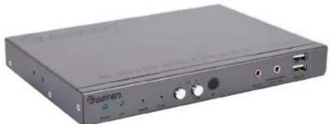
natural_image
Exterior view of a gray electronic device with ports and connectors (no visible text or symbols)Important Safety Instructions
- Read these instructions.
- Keep these instructions.
- Heed all warnings.
- Follow all instructions.
- Do not use this product near water.
- Clean only with a dry cloth.
- Do not block any ventilation openings. Install in accordance with the manufacturer's instructions.
- Do not install or place this product near any heat sources such as radiators, heat registers, stoves, or other apparatus (including amplifiers) that produce heat.
- Do not defeat the safety purpose of the polarized or grounding-type plug. A polarized plug has two blades with one wider than the other. A grounding type plug has two blades and a third grounding prong. The wide blade or the third prong are provided for your safety. If the provided plug does not fit into your outlet, consult an electrician for replacement of the obsolete outlet.
- Protect the power cord from being walked on or pinched particularly at plugs, convenience receptacles, and the point where they exit from the apparatus.
- Only use attachments/accessories specified by the manufacturer.
- To reduce the risk of electric shock and/or damage to this product, never handle or touch this unit or power cord if your hands are wet or damp. Do not expose this product to rain or moisture.
- Unplug this apparatus during lightning storms or when unused for long periods of time.
- Refer all servicing to qualified service personnel. Servicing is required when the apparatus has been damaged in any way, such as power-supply cord or plug is damaged, liquid has been spilled or objects have fallen into the apparatus, the apparatus has been exposed to rain or moisture, does not operate normally, or has been dropped.
- Batteries that may be included with this product and/or accessories should never be exposed to open flame or excessive heat. Always dispose of used batteries according to the instructions
Warranty Information
For the latest warranty coverage information, refer to the Warranty and Return Policy under the Connect section of the Gefen website at http://www.gefen.com/connect/warranty-and-return-policy
Contact Us
Technical Support
1-707-283-5900 1-800-472-5555
8:00 AM to 5:00 PM Monday - Friday, Pacific Time
support@gefen.com
Web
http://www.gefen.com
Mailing Address
Gefen
Nortek Security & Control, LLC
c/o Customer Service
1800 S McDowell Blvd.
Petaluma, CA 94954 USA
Operating Notes
Important
- When connecting through a Local Area Network, a managed gigabit switch is required. Jumbo Frame Support (8k or greater) and IGMP Snooping must be enabled.
- A dedicated LAN is not required but highly recommended.
Only the HDMI and DisplayPort™ Inputs and Outputs will pass content from HDCP-encoded sources such as Blu-ray players and PlayStation® console systems. Other formats do not support HDCP content. If HDCP encrypted content is being passed, the output will not be active. - We recommend that Sender and Receiver are first connected directly and functionality/performance is fully verified before integrating them into a Local Area Network.
· Always make sure that all units within a system are running the latest
This product has been specifically designed for use with the Gefen Syner-G™ Software Suite, available for download at www.gefen.com. The Gefen Syner-G™ Discovery and Show-Me features simplify initial IP configuration
· Always make sure that all units within a system are running the latest firmware. - Gefen highly recommends the Gefen EXT-CU-LAN Matrix Controller for setting up and controlling the operation of an AV-over-IP network using these products. Alternatively, the Syner-G™ software can be used for IP configuration and firmware updates.
- Shielded CAT-5e (or better) cables used between the Sender and the Receiver unit or between each unit and the IP switch, should not exceed 330 feet (100 meters).
- By default, all Sender and Receiver units are set to channel 0.
- The HDMI inputs and outputs on these products also support Single-Link DVI and its standard VESA resolutions. Dual-Link DVI is not supported.
- By default, each device is setup in unicast mode and the source device will use the EDID from the display (or other sink device) which is connected to the Receiver unit.
If terminating network cables in the field, please adhere to the TIA/EIA568B specification. See the Network Cable Diagram (page 175) for details.
Operating Notes
Supported USB Devices
▶ HID-class devices: keyboard, mouse, joystick, and touch panels.
▶ Bulk-only storage devices: USB flash drive, most storage devices, DVD-ROM, card readers, and printers.
- Known supported devices
▶ USB to RS-z32 adapter.
▶ Mobile devices: Android, iOS mobile devices.
Connectivity devices: infrared remote controller, Bluetooth dongle.
▶ Security devices: Key dongle, security card reader.
▶ Full-speed USB audio devices.
- Known Limits:
▶ High-speed isochronous devices, such as webcams are NOT supported.
Licensing
This product uses software that is subject to open source licenses, including one or more of the General Public License Version 2 and Version 2.1, Lesser General Public License Version 2.1 and Version 3, BSD, and BSD-style licenses. Distribution and use of this product is subject to the license terms and limitations of liability provided in those licenses. Specific license terms and Copyright Notifications are provided in the source code. For three years from date of activation of this product, any party may request, and we will supply for software covered by an applicable license (e.g. GPL or LCPL), a complete machine-readable copy of the corresponding open source code on a medium customarily used for software interchange. The following software and libraries are included with this product and subject to their respective open source licenses:
jQuery
Linux
Features & Packing List
Features
- Extends video, USB, RS-232, z-way analog audio, and IR, using a Gigabit Local Area Network
· Independent video, USB, RS-232, IR, and audio routing ^4 - Backward-compatible with first generation Gefen AV over IP products
HDMI and DisplayPort™ products support input resolutions up to 4K 60Hz 4:2:0 and output resolutions up to 4K 30Hz 4:4:4 - DVI and VGA products support input and output resolutions up to 108op Full HD and 1920x1200 (WUXGA)
- Video output on Sender unit for local monitoring of the source (except DisplayPort")
- KM Emulation feature facilitates real-time, simultaneous Keyboard and Mouse control of each source from all connected workstations
- Integrated scaler ensures maximum compatibility and best possible viewing experience with different contents and displays
- Built-in video wall controller accommodates any number of rows and columns up to 16x76
Built-in Audio De-Embedder on HDMI and DisplayPort™ Receivers breaks out 2 channel analog, 2 channel PCM, and up to 5.1 channels of Bitstream audio from the HDMI signal, allowing the audio content to be sent to external amplifiers and music distribution systems for added impact - MFU (Mass-Firmware-Update), quick and automated configuration, and enhanced control capabilities and system security when used with the Gefen EXT-CU-LAN Matrix Controller
- Enhanced API for added functionality with third-party control systems
- Built-in web interface, Telnet, and UDP
- Compatible with the Gefen Keyboard Switching Controller software, available for download at www.gefen.com
• Supports 39,900 Senders and a combination of over 65,000 Sender and Receiver units, depending on the network bandwidth and number of ports on your network switch - Two USB 2.0 ports with data rates up to 480 Mbps and backward-compatibility with USB 1.1
- Two USB 1.1 ports with KM Emulation, for use with Human Interface Devices (H.I.D.)
- 802.3af standard Power-over-Ethernet allows the new Sender and Receiver units to be powered through a standard DoE enabled IP network switch, without the need for
Features & Packing List
- Mode switch on Sender for sharpness or motion-optimization of image
Field-updatable firmware via EXT-CU-LAN controller or the built-in web server interface
- Locking power supply connectors
- Half-rack width Sender and Receiver enclosures are rack-mountable using EXT-RACK-1U-CRY
- Sender and Receiver can also be surface-mounted using the included L-brackets
- Low profile Receiver enclosure features an IR Extender port and can be hidden away behind the display
* Features and specifications are subject to change without notice.
** Pending features to be activated via an upcoming firmware update.
All trademarks and registered trademarks are properties of their respective owners.
Packing List - Sender Unit
The following items are included in the Sender Unit package. If any of these items are not present in the box when you first open it, please contact Gefen Technical Support as soon as possible.
(1) Sender unit
(1) SV 2.6A Power Supply
(4) Self-Adhesive Rubber-Feet
(2) L-Shaped Mounting Brackets
(4) Machine screws for L-Shaped Mounting Brackets
(2) Machine screws for EXT-RACK-1U-CRY (sold separately)
(1) Quick-Start Guide
Packing List - Receiver Unit
The following items are included in the Receiver Unit. If any of these items are not present in the box when you first open it, please contact Gefen Technical Support as soon as possible.
(1) Receiver unit
(1) 5V 4A Power Supply
(2) ACD.....C.1
Table of Contents
Introduction....11 Sender Unit....11 Receiver Unit....14
Installation....17 Local Area Network (LAN) Connection....17 Using a Direct Connection....22 Supplementary Connections....24 Sample Wiring Diagram....25
LED Status....26 Link....26 Power....26
Setting the Video Channel ....27 Setting the Channel using the Web Interface ....27 Setting the Channel using the Front Panel ....28
Blocking & Masking Video 31
Unicast & Multicast Modes....33 Configuring Unicast Mode....33 Switching between Sender units in Unicast mode....35 Configuring Multicast Mode....38
Discovery Mode ....40 Cefen Syner-G Discovery ....40 Finding Your Device ....41
RS-232 Control ....43 RS-232 under Unicast Mode ....45 RS-232 under Multicast Mode ....45
USB Control ....46 USB under Unicast Mode....46 USB under Multicast Mode....48 Active per request mode....51 Active on link mode....52
Audio Connections .... 53 Audio Sources and De-Embedding .... 55
a. _1 will be ill
Table of Contents
Setting the Video Mode 59
Using the Web interface....59
Changing the Password....60
Utilities....61
Reset using the Web Interface 61
Reboot using the Web Interface 63
Reboot using the Web Interface 64
Reboot using the Front Panel 65
Telnet Access....66
Commands....67
Discovery Service....67
Help 67
Network 67
Routing....68
RX Specific 69
Serial....70
System....70
TX Specific 70
USB 71
Video....71
Web Interface 71
Network Cable Diagram....175
Rack Tray Installation 176
Specifications ^* 177
Introduction
Sender Unit
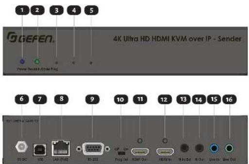
| ID | Name | Description |
| 1 | Power | This LED indicator glows solid blue when the unit is powered. |
| 2 | Link | This LED glows solid green when a link is established between the Sender and Receiver. |
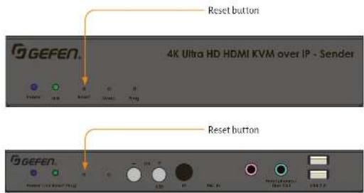
| 3 | Reset | Press this button, using the end of a paper clip or other pointed object, to perform a soft reset. |
| 4 | Mode | Press this button, using the end of a paper clip or other pointed object, to toggle between Graphic and Video modes. |
| 5 | Drop | This button is used for device returned. |
Introduction
ID Name Description
| 6 5V DC This power receptacle is used to connect the included 5V DC power supply. An external power supply is not required when connecting to a PoE-enabled switch using the LAN (PoE) port. | |
| 7 USB Connect a USB cable from the computer to this USB port. | |
| 8 LAN (PoE) Connect a CAT-5e or better cable up to 330 feet/100 meters, from this port to a PoE-capable network switch. If a PoE switch is not available, then the included 5V DC power supply must be connected to the Sender unit. | |
| 9 RS-232 Connect an DB-9 cable from this port to a RS-232 automation control unit. See RS-232 Control (page 43) for more information. | |
| 10 Prog Sel For normal operation, this switch should be in the Off position. Setting this switch to the On position, places the unit in the ready-state for firmware recovery or debug operations. | |
| 11 Video Out (except DisplayPortTM) | Use a high quality video interconnect cable to the connect an AV source to the video Out port on the rear panel of the Sender unit. When using HDMI Senders, we recommend Cefen cables. |
| 12 Video In Use a high quality video interconnect cable to the connect an AV source to the video In port on the rear panel of the Sender unit. When using HDMI and DisplayPortTM Senders, we recommend Cefen cables. | |
Introduction
ID Name Description
| 13 IR In/Ext Connect an IR Extender (Cefen part no. | EXT-RMT-EXTIRN) to this port. Alternatively,connect a 3.5mm mini-stereo connectorfrom this port to the output of anautomation system with an electrical IRoutput. | |
| 14 IR Out Connect an IR Emitter (Cefen part no. | EXT-IREMIT) from this port to the IR sensor of thedevice to be controlled. | |
| 15 Line In Connect a 3.5mm mini-stereo cable from thisport to the analog audio source. | ||
| 16 Line Out Connect a 3.5mm mini-stereo cable from thisport to an amplifier or other audio outputdevice. | ||
Introduction
Receiver Unit
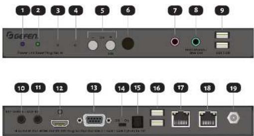
| ID | Name | Description |
| 1 | Power | This LED indicator glows solid blue when the unit is powered. |
| 2 | Link | This LED glows solid green when a link is established between the Sender and Receiver. |
| 3 | Reset | Press this button, using the end of a paper clip or other pointed object, to perform a soft reset. |
| 4 | Prog | This button is used for device recovery operations, in the event of a firmware update or other failure. |
| 5 | CH -/+ | These buttons serve two purposes. n) Press the -/+ buttons button to decrement / increment, respectively, the current channel number. See Setting the Video |
Introduction
| ID Name Description | ||
| 6 IR This IR sensor receives and passes signals from | an IR remote control to the selected Sender unit. | |
| 7 Mic In Connect a microphone to this port. | ||
| 8 | Headphones/ Line Out | Connect a pair of headphones or powered speakers to this port. |
| 9 USB 2.0 Connect up to two USB 2.0 devices to these USB ports. For USB 1.1 devices, use the USB 1.1 ports. Please note that KM Emulation feature is only available on the USB 1.1 ports on the back panel. It is not available with these two USB 2.0 ports. | ||
| 10 IR In/Ext Connect an IR Extender (Gefen part no. | EXT-RMT-EXTIRN) to this port. Alternatively, connect a 3.5mm mini-stereo connector from this port to the output of an automation system with an electrical IR output. | |
| 11 IR Out Connect an IR Emitter (Gefen part no. | EXT-IREMIT) from this port to the IR sensor of the device to be controlled. | |
| 12 | Video Out | Use a high quality video interconnect cable to the connect a display to the video Out port on the rear panel of the Receiver unit. When using HDMI and DisplayPortTM Receivers, we recommend Gefen cables. |
Introduction
ID Name Description
| 13 RS-232 Connect a DB-9 cable from the Receiver unit to the display or another device to be controlled. See RS-232 Control (page 43) for more information. | |
| 14 Prog Sel For normal operation, this switch should be in the Off position. Setting this switch to the On position, places the unit in the ready-state for firmware recovery or debug operations. | |
| 15 | Opt Out (except VGA) Connect a digital audio cable with a TOSLINK* connectors from this port to the digital audio input of an AV receiver or amplifier. |
| 16 USB 1.1 Connect up to two USB 1.1 or HID devices (such as keyboard, mouse, or touchscreen) to these USB ports. For USB 2.0 devices, use the USB 2.0 ports. Please note that the KM Evolution feature only works with these two USB 1.1 ports. It is not available with the USB 2.0 ports. | |
| 17 LAN 1 Use this port to connect IP-enabled devices, or to daisy-chain additional Receiver units (only when a single source is used, otherwise bandwidth may be compromised). CAT-sy or better cables up to 330 feet/100 meters. This port is NOT PoE-capable. | |
| 18 LAN 2 (PoE) Connect a CAT-sy or better cable up to 330 feet/100 meters, from this port to a PoE-capable network switch. If a PoE switch is not available, then the included 5V DC power supply must be connected to the Receiver unit. | |
| 19 5V DC This power receptacle can be used to connect the included 5V DC power supply. An external power supply is not required when connecting | |
Installation
The Gen z.o KVM over IP Sender and Receiver units can be connected directly or through a Local Area Network (LAN). Both installations will be covered.
Local Area Network (LAN) Connection
When connecting the Sender and Receiver units to a Local Area Network (LAN), DHCP, static, or APIPA (Automatic Private IP Addressing) IP modes can be used. DHCP mode will use the DHCP server to automatically assign an IP address for each Sender and Receiver unit that is connected to the network. Static IP mode will allow the IP address for each Sender and Receiver unit to be configured manually. Contact your network administrator if necessary. APIAP mode assigns a class-BIP address, in the 169.254.x.x range; to the Sender and Receiver units, if a DHCP server is not available.
- Connect a CAT-5e (or better) cable between the LAN (PoE) port on the Sender unit and a Gigabit PoE-enabled IP switch.
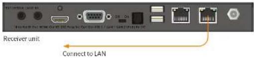
- Connect LAN 2 (PoE) on the Receiver unit to the same network switch. Each cable run can be up to 330 feet (100 meters).
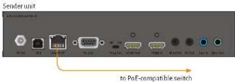
- If NOT USING A PoE-compliant switch, then connect the included 5V DC power supplies to the Sender and Receiver units.
Important
If the IP switch is PoE-compliant and the Sender and Receiver are connected through their PoE ports, external power supplies will not be required. However, additional Receivers or other devices connected to the LAN I port of a Receiver will require an external power supply.
Installation
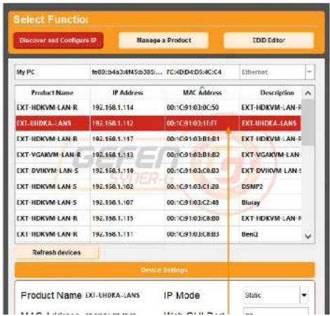
- Launch the Gefen Syner-G™ app to discover the IP address of the Sender/Receiver unit. See the Gefen Syner-G™ User Manual for more information.
- Click the desired unit from the list. The currently selected unit will be highlighted in red.
- Use the fields in the Device Settings section to change the IP settings, as necessary.
Installation
- Once all IP settings have been adjusted, click the Apply button.
- Click the Reboot button to apply changes.
- Repeat steps 4-7 for each Sender and Receiver unit as necessary.
Note
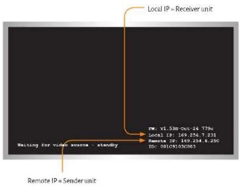
The IP address of both the Sender and Receiver unit can be viewed by disconnecting the source device. Remove the HDMI cable between the Sender unit and the source device. The IP address of the Sender and Receiver will be displayed as shown
- Open your Web browser and enter the IP address of the desired Sender or Receiver unit in the address bar.
Installation
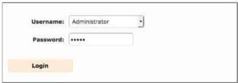
- The Login screen will be displayed
- In order to change network settings, you must login as "Administrator". Select the "Administrator" username from the drop-down list.
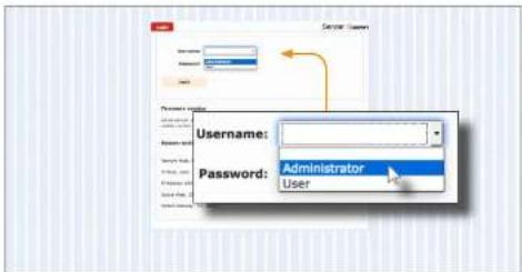
- Type the password in the Password field. The default password for "Administrator" is admin. The password is case-sensitive and will be masked as it is entered.
Note
Passwords and operating features can be changed when logged in as Administrator. The User option has limited access. To change password credentials, see Changing the Password (page 60) for more information.
Installation
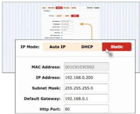
- Click the desired IP Mode button.
If Static mode is selected, then enter the IP Address, Subnet Mask, and Default Gateway. Contact your system administrator if necessary.
If DHCP mode is selected, then the IP address, subnet mask, and default gateway will be specified by the DHCP server.
- Click the Apply button to save the changes. This operation will require a reboot.
- Click the Reboot button near the bottom of the page.
- Repeat steps 12 - 21 for each Sender and Receiver to be configured.
- After the desired IP settings have been applied, set the video channel for each Sender unit. See Setting the Video Channel (page 27) for more information.
Installation
Using a Direct Connection
By default, all Senders and Receivers are shipped in APIPA (Auto) mode. This network mode is used for directly connecting Sender and Receiver units to one another. In APIPA mode, each Sender and Receiver unit assigns itself a unique IP address within the range of 169.254.x.x. Using a direct connection each unit can remain in Auto mode of can be assigned a static of DHCP IP address using the Cefen Syner-C software or manually through the built-in web interface.
- Connect an HDMI cable to connect the source to the HDMI In port on the Sender unit.
- Connect an HDMI cable from the display to the HDMI Out port on the Receiver unit.
- Connect a CAT-se (or better) cable from the LAN (PoE) port on the Sender unit to the LAN1 or LAN2 (PoE) port on the Receiver unit. The other LAN port can then be used for connecting (daisy-chaining) an additional Receiver unit. Each cable run can be up to 330 feet (100 meters). Please note that PoE is not active in direct connection. The Sender and all connected Receivers will need to be powered using their external power supplies.
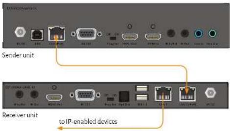
- Connect the included 5V DC locking power supplies to both the Sender unit and Receiver unit. Do not overtighten the locking connectors. Plug the power supplies to available electrical outlets.
Installation
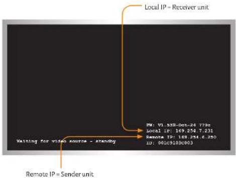
- Make note of both IP addresses. These IP addresses can be entered in a Web browser to access the built-in Web interface.
- See Local Area Network (LAN) Connection (page 17) and follow steps 4 - 20, in order to access the built-in Web interface.
- Set the video channel. By default, both the Sender and Receiver unit are set to channel 0. See Setting the Video Channel (page 27) for more information.
- Once both Sender and Receiver units are configured using the built-in Web interface, the shielded CAT-se cable, between the PC and the Receiver unit, can be disconnected.
- See Supplementary Connections (page 24) for instructions on connecting USB, IR, RS-232, and audio cables.
Installation
Supplementary Connections
USB
See USB Control (page 46) for more information on using USB devices.
- Connect a USB cable from the computer to the USB port on the Sender unit.
- Connect a maximum of two USB 2.0 devices to the USB 2.0 ports, on the front panel of the Receiver unit. For USB 1.1 devices, connect the devices to the USB 1.1 ports.
IR
- Connect an IR Emitter (Cefen part no. EXT-IREMIT) to the Sender unit and attach it to the IR sensor on the device to be controlled.
- Connect an IR Extender (Gefen part no. EXT-RMT-EXTIRN) to the Receiver unit if the IR sensor will not be within line-of-site for proper IR control.
▶ Audio
See Audio Connections (page 53) for more information on using audio devices.
- Connect a 3.5mm mini-stereo cable from the Line In port on the Sender unit to an audio source.
- Connect a pair of powered speakers (or another audio output device) to the Line Out port on the Receiver unit.
- Connect a USB microphone / headset to one of the USB 2.0 ports on the Receiver unit
- Connect a pair of powered speakers (or another audio output device) to the Line Out port on the Sender unit.
RS-232
- Connect an RS-232 cable from the PC or automation system to the RS-232 port on the Sender unit.
Installation
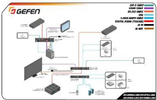
Sample Wiring Diagram
flowchart
graph TD
    A["GEFEN"] --> B["PC"]
    B --> C["PC"]
    C --> D["MT"]
    D --> E["MT"]
    E --> F["MT"]
    F --> G["MT"]
    G --> H["MT"]
    H --> I["MT"]
    I --> J["MT"]
    J --> K["MT"]
    K --> L["MT"]
    L --> M["MT"]
    M --> N["MT"]
    N --> O["MT"]
    O --> P["MT"]
    P --> Q["MT"]
    Q --> R["MT"]
    R --> S["MT"]
    S --> T["MT"]
    T --> U["MT"]
    U --> V["MT"]
    V --> W["MT"]
    W --> X["MT"]
    X --> Y["MT"]
    Y --> Z["MT"]
    Z --> AA["MT"]
    AA --> AB["MT"]
    AB --> AC["MT"]
    AC --> AD["MT"]
    AD --> AE["MT"]
    AE --> AF["MT"]
    AF --> AG["MT"]
    AG --> AH["MT"]
    AH --> AI["MT"]
    AI --> AJ["MT"]
    AJ --> AK["MT"]
    AK --> AL["MT"]
    AL --> AM["MT"]
    AM --> AN["MT"]
    AN --> AO["MT"]
    AO --> AP["MT"]
    AP --> AQ["MT"]
    AQ --> AR["MT"]
    AR --> AS["MT"]
Note
The wiring diagrams above show IR Emitters (Cefen part no. EXT-IREMIT), IR Extender Modules (Cefen part no. EXT-RMT-EXTIRN), and various interconnect cables that are not included with the product. These Emitters, Extender Modules, and select cables are available for purchase from your Gefen dealer or distributor.
LED Status
The Power and Link LED indicators on the Sender and Receiver unit provide basic information
on their current status.
The information, in the tables below, applies to both the Sender and Receiver unit.
Link
| Status Description | |
| Off · Connection is not established. | |
| · Check the cable between the Sender and Receiver unit. | |
| On | · Connection is established and video is streaming. |
| Blinking | · System is in a state of transition. Connection is established but streaming has not started.· No video source detected.· Check that the Receiver unit is connected to the host. |
Power
| Status Description | |
| Off - No power. | ○ |
| On - Power is on and the system is ready. | |
| Blinking | System is booting (not ready). |
Setting the Video Channel
In order for a Sender and Receiver unit to communicate with one another, they must both be set to the same video channel. This is similar to changing the channel on a set-top box in order to view a different program. Pressing and releasing either the CH + or CH - buttons on the front of the Receiver unit can also be used to change the video channel. Both methods will be covered in this section. By default, all Sender and Receiver units are set to channel o (zero).
Setting the Channel using the Web Interface
- Access the Web interface by entering the IP address of the desired Sender or Receiver unit.
- Login as "Administrator" or "User".
- Click the Functions tab. The current channel is displayed within the Channel Setup window group.
- Type the desired channel number. Channel numbers can range from 0 to 39900.
- Click the Apply button on the right-hand side of Channel Setup window group.
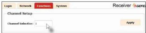
- The following message will be displayed, at the top of the page, indicating that the selected channel has been applied.
i Success: Channel Selected.
If the entered value is invalid, then the following message will be displayed:
Error: Channel value range:0\~39900
- Access the Web interface of the next unit (Sender or Receiver) by entering its IP address
Setting the Video Channel
Setting the Channel using the Front Panel
- Press the - or +/USB button to display the current channel number. Channel numbers range from 0 to 39900.

Receiver unit
- The current video channel of the Receiver unit will be shown on the connected display.
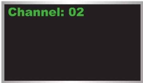
- While the current video channel is being displayed, press and release the Switch button on the Receiver unit. The Receiver unit will change to the next available video channel that is being used by a Sender unit.
Setting the Video Channel
-
Once the current channel is displayed, do one of the following:
-
Press the - button to decrement the current channel number
-
Press the +/USB button to increment the current channel number.
-
To set the video channel on a Sender unit, use the Web interface. See Setting the Channel using the Web Interface (page 27) for more information.
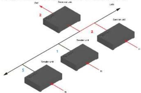
The illustration below shows one Receiver unit and three Sender units. The numbers indicate the video channel for each unit. Here, the Receiver unit is currently set to channel z and is receiving the signal from the Sender unit, set to channel z.
flowchart
graph TD
    A["Source unit"] -->|2| B["Lab"]
    C["Sample unit"] -->|2| B
    D["Batch unit"] -->|1| E["Output"]
    F["Source unit"] -->|5| G["Output"]
    H["Sample unit"] -->|n| I["Output"]
To switch the channel, and view the source that is connected to the Sender on channel 5, press and release the +/USB button to increment the video channel until the display shows the number 5.
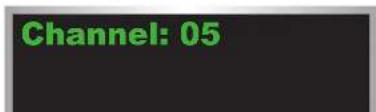
Setting the Video Channel
- The Receiver unit, on channel 5, is now receiving the signal from the Sender unit on channel 5.
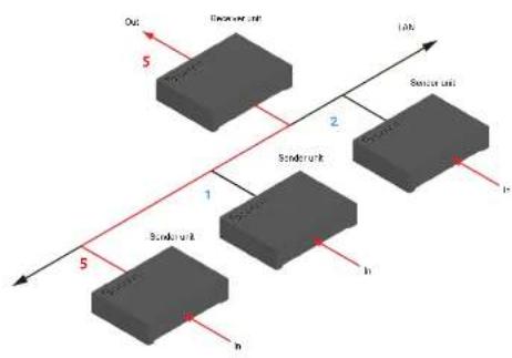
flowchart
graph TD
    A["Sensor unit"] -->|1| B["Sensor unit"]
    B -->|2| C["Output Unit"]
    D["Sensor unit"] -->|3| E["Sensor unit"]
    E -->|4| F["Output Unit"]
    G["Sensor unit"] -->|5| H["Sensor unit"]
    H -->|6| I["Output Unit"]
    style A fill:#f9f,stroke:#333
    style B fill:#f9f,stroke:#333
    style C fill:#f9f,stroke:#333
    style D fill:#f9f,stroke:#333
    style E fill:#f9f,stroke:#333
    style F fill:#f9f,stroke:#333
    style G fill:#f9f,stroke:#333
    style H fill:#f9f,stroke:#333
    style I fill:#f9f,stroke:#333
Blocking & Masking Video
Use the Block Video option on a Sender unit to prevent video from being transmitted to each of the connected Receiver units (multicast mode only). Use the Mask Video option to selectively block video on the desired Receiver units.
Mask Video
- Access the Web interface of a Receiver unit by entering the IP address in the address bar of the browser.
- Login as "Administrator".
- Click the Functions tab.
- Under the Video over IP window group, check the Mask Enable box to mask the video. Deselect this check box to unmask (enable) video.
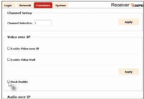
- Click the Apply button within the Video over IP group.
- Repeat steps 1 through 5 for each Receiver unit in the system
Blocking & Masking Video
Block Video
Note
The Block Enable option is only applicable in multicast mode.
- Access the Web interface of a Sender unit by entering the IP address in the address bar of the browser
- Login as "Administrator".
- Click the Functions tab.
- Under the Video over IP window group, check the Block Enable box to block the video. Deselect this check box to unblock (enable) video.
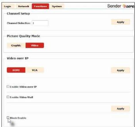
Unicast & Multicast Modes
Configuring Unicast Mode
The term unicast is used to describe a configuration where information is sent from one point to another point. It is possible to have multiple Sender and Receiver units connected in a system. However, in unicast mode a Sender unit can communicate with only one Receiver unit at a time. In unicast mode, the Gefen AV over IP products function similar to a KVM switcher.
Note
The Gefan AV over IP Sender and Receiver units are shipped from the factory in unicast mode.
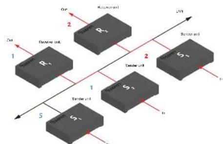
The illustration, below, shows 3 Sender units (S1, S2, and S3) and 2 Receiver units (R1 and R2) on a network, operating in unicast mode. The video channels are notated in blue.
Figure 2.1 - Unicast mode: A Sender unit can communicate with only one Receiver unit at a time.
flowchart
graph TD
    A["Input"] --> B["Component 1"]
    B --> C["Component 2"]
    C --> D["Output"]
    style A fill:#000,stroke:#000,color:#fff
    style B fill:#000,stroke:#000,color:#fff
    style C fill:#000,stroke:#000,color:#fff
    style D fill:#000,stroke:#000,color:#fff
    subgraph Input
        R1["R₁"]
        S1["S₂"]
        T1["S₃"]
    end
    subgraph Component 1
        R2["R₂"]
        S2["S₃"]
        T2["S₄"]
    end
    subgraph Component 2
        R3["R₃"]
        S3["S₃"]
        T3["S₄"]
    end
    subgraph Output
        U1["U₁"]
        V1["V₁"]
    end
    R1 --> R2
    R2 --> S2
    S2 --> T2
    T2 --> U1
    U1 --> V1
    V1 --> U2["U₂"]
    U2 --> V2["V₂"]
    style A fill:#000,stroke:#000,color:#fff
    style B fill:#000,stroke:#000,color:#fff
    style C fill:#000,stroke:#000,color:#fff
    style D fill:#000,stroke:#000,color:#fff
    style E fill:#000,stroke:#000,color:#fff
    style F fill:#000,stroke:#000,color:#fff
    style G fill:#000,stroke:#000,color:#fff
    style H fill:#000,stroke:#000,color:#fff
    style I fill:#000,stroke:#000,color:#fff
    style J fill:#000,stroke:#000,color:#fff
    style K fill:#000,stroke:#000,color:#fff
    style L fill:#000,stroke:#000,color:#fff
    style M fill:#000,stroke:#000,color:#fff
    style N fill:#000,stroke:#000,color:#fff
    style O fill:#000,stroke:#000,color:#fff
    style P fill:#000,stroke:#000,color:#fff
    style Q fill:#000,stroke:#000,color:#fff
    style R fill:#666,stroke:#333
    style S fill:#666,stroke:#333
    style T fill:#666,stroke:#333
    style U fill:#666,stroke:#333
    style V fill:#666,stroke:#333
    style W fill:#666,stroke:#333
    style X fill:#666,stroke:#333
-
Access the Web interface for each Sender and Receiver unit that will be using unicast mode. In this example, we will start with Receiver unit R1.
-
Login as "Administrator".
Unicast & Multicast Modes
-
Click the Network tab.
-
Click the Unicast button under the Network Mode window group. When selected, the Unicast button will be highlighted in red.
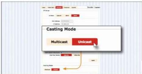
-
Click the Apply button in the lower-right corner of the Network Mode group.
-
The following message will be displayed, at the top of the page, indicating that the casting mode has been applied to the Sender or Receiver unit.
Success: New casting mode applied
- Click the Reboot button at the bottom of the page. If the Reboot button is not clicked, the following message will be displayed, indicating that the unit must be rebooted.
Warning: Reboot for new settings to take effect
- Repeat steps 1-7 in order to configure the Sender unit for unicast mode.
Important
When switching between unicast and multicast modes, both Sender and Receiver units must be set to the same mode.
Unicast & Multicast Modes
Switching between Sender units in Unicast mode
When multiple Sender and Receiver unit are used in unicast mode, the Gefen AV over IP Sender and Receivers behave as a switcher. In unicast mode, a Sender unit can communicate with only one Receiver unit at a time.
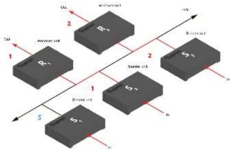
In the example below, Receiver unit R1 will be switched to receive the source connected to Sender unit S1. To do this, simply change the video channel.
Figure 2.2 - Unicast mode: Receiver unit R1 is connected to Sender unit S2.
flowchart
graph TD
    A["Block R1"] -->|1| B["Block S2"]
    C["Block S2"] -->|5| B
    D["Block R2"] -->|2| B
    E["Block S2"] -->|1| B
    F["Block R2"] -->|2| B
    G["Block S2"] -->|1| B
    H["Block R2"] -->|2| B
    I["Block S2"] -->|1| B
    J["Block R2"] -->|2| B
    K["Block S2"] -->|1| B
    L["Block R2"] -->|2| B
    M["Block S2"] -->|1| B
    N["Block R2"] -->|2| B
    O["Block S2"] -->|1| B
    P["Block R2"] -->|2| B
    Q["Block S2"] -->|1| B
    R["Block R2"] -->|2| B
    S["Block S2"] -->|1| B
    T["Block R2"] -->|2| B
    U["Block S2"] -->|1| B
    V["Block R2"] -->|2| B
    W["Block S2"] -->|1| B
    X["Block R2"] -->|2| B
    Y["Block S2"] -->|1| B
    Z["Block R2"] -->|2| B
    AA["Block S2"] -->|1| B
    AB["Block R2"] -->|2| B
    AC["Block S2"] -->|1| B
    AD["Block R2"] -->|2| B
    AE["Block S2"] -->|1| B
    AF["Block R2"] -->|2| B
    AG["Block S2"] -->|1| B
    AH["Block R2"] -->|2| B
    AI["Block S2"] -->|1| B
    AJ["Block R2"] -->|2| B
    AK["Block S2"] -->|1| B
    AL["Block R2"] -->|2| B
    AM["Block S2"] -->|1| B
    AN["Block R2"] -->|2| B
    AO["Block S2"] -->|1| B
    AP["Block R2"] -->|2| B
    AQ["Block S2"] -->|1| B
    AR["Block R2"] -->|2| B
    AS["Block S2"] -->|1| B
    AT["Block R2"] -->|2| B
    AU["Block S2"] -->|1| B
    AV["Block R2"] -->|2| B
    AW["Block S2"] -->|1| B
    AX["Block R2"] -->|2| B
    AY["Block S2"] --> AZ["Output"]
    AZ --> BA["Output"]
- Access the Web interface for Receiver unit R1.
- Login as "Administrator".
- Click the Network tab and change the video channel. Refer to Setting the Video Channel (page 27) if necessary.
- Click the Apply button.
- The following message will be displayed, at the top of the page, indicating that the new channel has been applied to the Sender or Receiver unit.
Unicast & Multicast Modes
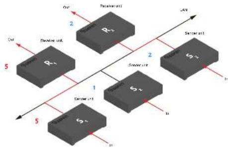
Figure 2.3 - Unicast mode: Receiver unit R1 is now connected to Sender unit S1.
flowchart
graph TD
    A["Sensor Unit 1"] -->|1| B["Sensor Unit 2"]
    B -->|2| C["Sensor Unit 3"]
    C -->|3| D["Sensor Unit 4"]
    D -->|4| E["Sensor Unit 5"]
    style A fill:#f9f,stroke:#333
    style B fill:#f9f,stroke:#333
    style C fill:#f9f,stroke:#333
    style D fill:#f9f,stroke:#333
    style E fill:#f9f,stroke:#333
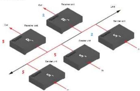
Now, observe the result when both Sender S1 and S2 are set to channel 5:
Figure 2.4 - Unicast mode violation: Two Sender units (S1 and S2) using the same video channel.
flowchart
graph TD
    A["Sensor unit R1"] -->|5| B["Decoupling unit"]
    C["Sensor unit R2"] -->|2| D["Decoupling unit"]
    E["Sensor unit S1"] -->|5| F["Decoupling unit"]
    G["Sensor unit S2"] -->|2| H["Decoupling unit"]
    I["Sensor unit S3"] -->|5| J["Decoupling unit"]
    K["Out"] --> L["Out"]
    M["Cut"] --> N["Cut"]
Unicast & Multicast Modes
When using unicast mode, each of the Sender units must be assigned a unique channel and should never be changed. Use the Receiver unit to switch (channels) between Sender units.
Note
In anisost mode, if an additional Sender unit is introduced into a system with the same channel as another Sender unit, then the Receiver unit will continue to receive audio/video data from the Sender unit which was connected first.
Unicast & Multicast Modes
Configuring Multicast Mode
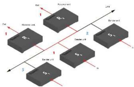
The term multicast is used to describe a configuration where information is sent from one or more points to a set of other points. For example, a single Sender unit can transmit data to multiple Receiver units. In addition, if multiple Sender units are used, each Sender unit can transmit data to any Receiver that is not already receiving data from another Sender unit. In multicast mode, the Senders and Receivers function similar to a KVM matrix.
The illustration, below, shows 3 Sender units (S1, Sz, and Sz) and z Receiver units (R1 and R2) on a network, operating in multicast mode. The video channels are shown in blue.
Figure 2.5 - Multicast mode: A Sender unit can communicate with multiple Receiver units.
flowchart
graph TD
    A["Input"] --> B["R1"]
    B --> C["R2"]
    C --> D["Output"]
    style A fill:#999
    style B fill:#ccc
    style C fill:#ccc
    style D fill:#ccc
    subgraph Input
        E["R1"] --> F["R2"]
    end
    subgraph SeriesUnit
        G["S1"] --> H["S2"]
    end
    I["Output"] --> J["S3"]
    K["Input"] --> L["S4"]
    M["Output"] --> N["S5"]
    style I fill:#ccc
    style K fill:#ccc
    style M fill:#ccc
    style N fill:#ccc
-
Access the Web interface for each Sender and Receiver unit that will be using multicast mode. In this example, we will start with Receiver S2.
-
Login as "Administrator".
Unicast & Multicast Modes
-
Click the Network tab.
-
Click the Multicast button under the Network Mode window group. When selected, the Multicast button will be highlighted in red.
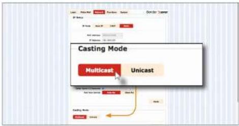
- Click the Apply button in the lower-right corner of the Network Mode group.
The following message will be displayed, at the top of the page, indicating that the casting mode has been applied to the Sender or Receiver unit.
Success: New casting mode applied.
If a display is connected to the Receiver unit, then the message "Starting USB" will be displayed. For more information on using USB under multicast mode, see USB under Multicast Mode (page 48).
- Click the Reboot button at the bottom of the page. If the Reboot button is not clicked, the following message will be displayed, indicating that the unit must be rebooted.
Warning: Reboot for new settings to take effect.
- Repeat the steps above in order to configure the Sender unit to multicast mode.
Discovery Mode
Gefen Syner-G Discovery
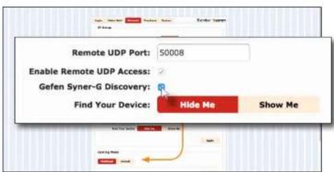
Enabling the Gefen Syner-G Discovery feature allows the Gefen Syner-C Software Suite or Gefen Discovery Tool App to locate a Sender and/or Receiver on a network. Once the software is able to locate the unit, IP settings can be changed as desired.
- Access the Web interface by entering the IP address of a Receiver or Sender unit.
- Login as "Administrator".
- Click the Network tab.
- Under the IP Setup window group, check the Gefen Syner-G Discovery box to allow the Gefen Syner-G software to locate the unit. If you do not want the unit to be discoverable, then un-check this box.
- Click the Apply button.
- Click the Reboot button at the bottom of the page to restart the unit and apply the change.
Discovery Mode
Finding Your Device
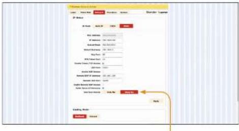
If several Sender and Receiver unit pairs are connected on a network, you may need to physically identify a particular Sender and/or Receiver unit. In such a case, use the Find Your Device feature.
- Access the Web interface by entering the IP address of a Receiver or Sender unit.
- Login as "Administrator".
- Click the Network tab.
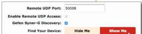
4 Under the IP Setup window group, click the Show Me button. By default, the Hide Me button will be selected.
Although shown, below, it is not necessary to have the Gefen Syner-G Discovery option enabled in order to use the Find Your Device feature.
Discovery Mode
- The following message will be displayed, at the top of the page, indicating that the LED indicators on the unit are blinking.
Success: Device is blinking!
- The Power and Link LED indicators will continue to blink until the Hide Me button is clicked.

Receiver unit (shown)
- Click the Hide Me button to stop both LED indicators from blinking.
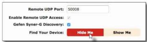
- The Power and Link LED indicators will stop blinking and the following message will be displayed at the top of the page.
③ Success: Device will stop blinking!
RS-232 Control
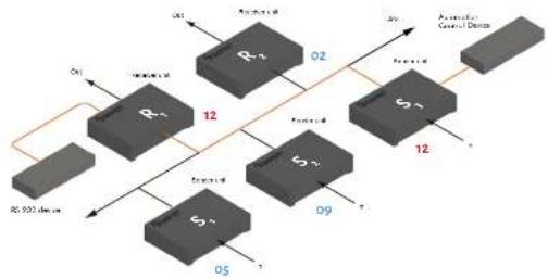
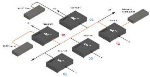
The Cefen AV over IP Sender and Receivers support RS-232 pass-through, allowing the control of remote RS-232 devices. The Sender and Receiver unit which are being used to pass-through the RS-232 data must be set to the same baud rate as the RS-232 host and client.
In the example below, an RS-232 device has been connected to Receiver R1. We want to control this product from Sender unit S3, using an automation control device. The channel numbers are listed in blue.
Figure 2.6 - Basic RS-232 connection
flowchart
graph TD
    R0["RS 930 device"] -->|12| R1["R1"]
    R1 -->|02| R2["R2"]
    R2 -->|12| R3["R3"]
    R3 -->|09| R4["R4"]
    R4 -->|12| R5["R5"]
    R5 -->|05| R6["R6"]
    R6 -->|1| R7["R7"]
    R7 -->|02| R8["R8"]
    R8 -->|12| R9["R9"]
    R9 -->|09| R10["R10"]
    R10 -->|12| R11["R11"]
    R11 -->|02| R12["R12"]
    R12 -->|12| R13["R13"]
    R13 -->|09| R14["R14"]
    R14 -->|12| R15["R15"]
    R15 -->|02| R16["R16"]
    R16 -->|12| R17["R17"]
    R17 -->|09| R18["R18"]
    R18 -->|12| R19["R19"]
    R19 -->|02| R20["R20"]
Table 2.1 - RS-232 settings for an arbitrary RS-232 device.
| Description Setting | |
| Baud rate | 19200 |
| Data bits | 8 |
| Parity | None |
| Stop bits | 1 |
| Hardware flow control | None |
RS-232 Control
- Access the Web interface for the Sender unit and login as "Administrator".
- Click the Functions tab.
- Locate the Serial over IP group and change the RS-232 settings to match the settings of the RS-232 device that is being used. In this case, we need to use the settings from Table 2.1 (see previous page).
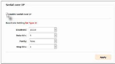
- Make sure that the Enable Serial over IP box is checked.
- Click the Apply button in the lower-right corner of the Serial over IP group.
Important
If Enable Serial over IP is not checked, then RS-232 pass-through will be disabled.
- The following message will be displayed, at the top of the page, indicating that the new Serial over IP options have been applied.
Success: New Serial over IP options applied.
- Click the Reboot button at the bottom of the page. If the Reboot button is not clicked, the following message will be displayed, indicating that the unit must be rebooted.
RS-232 Control
RS-232 under Unicast Mode
In unicast mode, a Sender unit will be able to communicate with only one Receiver unit at a time.
Figure 2.7 - In unicast mode, the host can talk to only one RS-232 device at a time.
flowchart
graph TD
    A["IP Address 222"] --> B["R1"]
    A --> C["S1"]
    A --> D["S4"]
    B --> E["Switch"]
    C --> F["Switch"]
    D --> G["Switch"]
    E --> H["Address"]
    F --> I["Address"]
    G --> J["Address"]
    H --> K["Internet"]
    I --> L["Internet"]
    J --> M["Internet"]
    K --> N["Internet"]
    L --> O["Internet"]
    M --> P["Internet"]
    N --> Q["Internet"]
    O --> R["Internet"]
    P --> S["Internet"]
    Q --> T["Internet"]
    R --> U["Internet"]
    S --> V["Internet"]
    T --> W["Internet"]
    U --> X["Internet"]
    V --> Y["Internet"]
    W --> Z["Internet"]
    X --> AA["Internet"]
    Y --> AB["Internet"]
    Z --> AC["Internet"]
    AA --> AD["Internet"]
    AB --> AE["Internet"]
    AC --> AF["Internet"]
    AD --> AG["Internet"]
    AE --> AH["Internet"]
    AF --> AI["Internet"]
    AG --> AJ["Internet"]
    AH --> AK["Internet"]
    AI --> AL["Internet"]
    AJ --> AM["Internet"]
    AK --> AN["Internet"]
    AL --> AO["Internet"]
    AM --> AP["Internet"]
    AN --> AQ["Internet"]
RS-232 under Multicast Mode
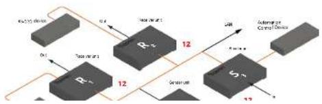
In multicast mode, a Sender unit can communicate with multiple Receiver units simultaneously.
Figure 2.8 - In multicast mode, the host can talk to multiple RS-232 devices.
flowchart
graph TD
    A["R1"] -->|0.4| B["R2"]
    B -->|12| C["V1"]
    C -->|12| D["V2"]
    D -->|12| E["Output"]
    F["External Control Devices"] -->|A/B| G["External Control Devices"]
    style A fill:#f9f,stroke:#333
    style B fill:#ccf,stroke:#333
    style C fill:#cfc,stroke:#333
    style D fill:#fcc,stroke:#333
    style E fill:#ffc,stroke:#333
USB Control
USB under Unicast Mode
When connecting USB devices to the Gefen AV over IP Senders and Receivers, the functionality is similar to that of video and RS-232. See RS-232 under Unicast Mode (page 45) for more information.
Note
The Sender and Receiver units shipped from the factory in unicast mode.
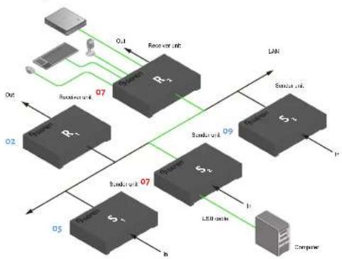
As an example, we will start with our original diagram and connect a computer to Sender unit Sz and a keyboard, mouse, USB drive, and USB micrheadset to Receiver unit Rz.
Figure 2.9 - Using USB devices under unicast mode.
flowchart
graph TD
    A["Router R1"] -->|Out| B["Switch R2"]
    B -->|Out| C["Switch R3"]
    C -->|Out| D["Switch R4"]
    D -->|Out| E["Switch R5"]
    E -->|Out| F["Switch R6"]
    F -->|Out| G["Switch R7"]
    G -->|Out| H["Switch R8"]
    H -->|Out| I["Switch R9"]
    I -->|Out| J["Switch R10"]
    J -->|Out| K["Switch R11"]
    K -->|Out| L["Switch R12"]
    L -->|Out| M["Switch R13"]
    M -->|Out| N["Switch R14"]
    N -->|Out| O["Switch R15"]
    O -->|Out| P["Switch R16"]
    P -->|Out| Q["Switch R17"]
    Q -->|Out| R["Switch R18"]
    R -->|Out| S["Switch R19"]
    S -->|Out| T["Switch R20"]
    T -->|Out| U["Switch R21"]
    U -->|Out| V["Switch R22"]
    V -->|Out| W["Switch R23"]
    W -->|Out| X["Switch R24"]
    X -->|Out| Y["Switch R25"]
    Y -->|Out| Z["Switch R26"]
    Z -->|Out| AA["Switch R27"]
    AA -->|Out| AB["Switch R28"]
    AB -->|Out| AC["Switch R29"]
    AC -->|Out| AD["Switch R30"]
    AD -->|Out| AE["Switch R31"]
    AE -->|Out| AF["Switch R32"]
    AF -->|Out| AG["Switch R33"]
    AG -->|Out| AH["Switch R34"]
    AH -->|Out| AI["Switch R35"]
    AI -->|Out| AJ["Switch R36"]
    AJ -->|Out| AK["Switch R37"]
    AK -->|Out| AL["Switch R38"]
    AL -->|Out| AM["Switch R39"]
    AM -->|Out| AN["Switch R40"]
    AN -->|Out| AO["Switch R41"]
    AO -->|Out| AP["Switch R42"]
    AP -->|Out| AQ["Switch R43"]
    AQ -->|Out| AR["Switch R44"]
    AR -->|Out| AS["Switch R45"]
    AS -->|Out| AT["Switch R46"]
    AT -->|Out| AU["Switch R47"]
    AU -->|Out| AV["Switch R48"]
    AV -->|Out| AW["Switch R49"]
    AW -->|Out| AX["Switch R50"]
    AX -->|Out| AY["Computer"]
USB Control
- Locate the USB over IP group and make sure the Enable USB over IP box is checked. This is the default setting. Note that in unicast mode, the Operation Mode is automatically set to Active on link and cannot be changed.
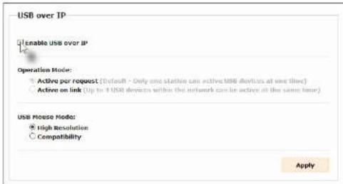
- Make sure that the USB Mouse Mode is set to High Resolution. This is the default setting. Use Compatibility mode only if using additional KVM switchers or other devices within the system that causes the mouse to behave erratically.
- Click the Apply button within the USB over IP group, then click the Reboot button at the bottom of the page.
- Connect the USB host (e.g. computer) to the USB port on the Sender unit.
- Connect a USB device (keyboard and/or mouse) to a USB port on the Receiver unit. Up to four USB devices (two USB 1.1 and two USB 2.0) can be connected per network in unicast mode.
- The keyboard and mouse (or other USB device) can now be used from the Receiver unit.
Important
When enabling or disabling USB over IP, the Apply and Reboot buttons must be clicked to apply changes.
USB Control
USB under Multicast Mode
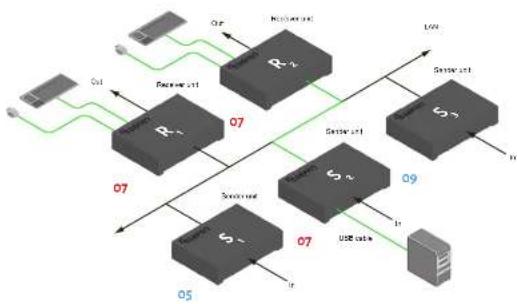
When connecting USB devices to the Cefen AV over IP Senders and Receivers, the functionality is similar to that of video and RS-232. There are two USB modes available in multicast mode: Active per request mode and Active on link mode.
Using the last example, another keyboard and mouse device has been connected to Receiver R1. This will allow us to control the computer from two separate locations. For purposes of clarity, the USB drive and mic/headset have been removed.
Figure 2.9 - Using USB devices under multicast mode.
flowchart
graph TD
    A["Router"] -->|Out| B["Switch"]
    B -->|07| C["R1"]
    C -->|07| D["Switch"]
    D -->|07| E["R2"]
    E -->|07| F["Switch"]
    F -->|07| G["R3"]
    G -->|07| H["Switch"]
    H -->|07| I["Switch"]
    I -->|07| J["Switch"]
    J -->|07| K["Switch"]
    K -->|07| L["Switch"]
    L -->|07| M["Switch"]
    M -->|07| N["Switch"]
    N -->|07| O["Switch"]
    O -->|07| P["Switch"]
    P -->|07| Q["Switch"]
    Q -->|07| R["Switch"]
    R -->|07| S["Switch"]
    S -->|07| T["Switch"]
    T -->|07| U["Switch"]
    U -->|07| V["Switch"]
    V -->|07| W["Switch"]
    W -->|07| X["Switch"]
    X -->|07| Y["Switch"]
    Y -->|07| Z["Switch"]
    Z -->|07| AA["Switch"]
    AA -->|07| AB["Switch"]
    AB -->|07| AC["Switch"]
    AC -->|07| AD["Switch"]
    AD -->|07| AE["Switch"]
    AE -->|07| AF["Switch"]
    AF -->|07| AG["Switch"]
    AG -->|07| AH["Switch"]
    AH -->|07| AI["Switch"]
    AI -->|07| AJ["Switch"]
    AJ -->|07| AK["Switch"]
    AK -->|07| AL["Switch"]
    AL -->|07| AM["Switch"]
    AM -->|07| AN["Switch"]
    AN -->|07| AO["Switch"]
    AO -->|07| AP["Switch"]
    AP -->|07| AQ["Switch"]
    AQ -->|07| AR["Switch"]
    AR -->|07| AS["Switch"]
    AS -->|07| AT["Switch"]
    AT -->|07| AU["Switch"]
    AU -->|07| AV["Switch"]
    AV -->|07| AW["Switch"]
    AW -->|07| AX["Switch"]
- Make sure the desired Sender and Receiver units are set to multicast mode. Refer to Configuring Multicast Mode if necessary.
- Access the Web interface for the Sender unit.
- Click the Functions tab
USB Control
![USB over IP Enable USB over IP Operation Mode: Active per request [Default: Only one station can active USB devices at one time] Active on link (Up to 4 USB devices within the network can be active at the same time) USB Mouse Mode: High Resolution Compatibility Apply](/content/2026/05/926255/images/f4b02866208e571533508732c1d20cd13795814a755d7ad1e6e538320456faf8.jpg)
Note that in multicast mode, the Operation Mode for both Sender and Receiver units are automatically set to Active per request mode.
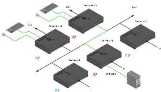
Under Active per request mode, multiple USB devices may be present on one or more Receiver units. However, only one Receiver unit can have USB control at a time.
By default, the first Receiver unit connected to the system will have USB control. In the example, below, Receiver unit R2 currently has control (we arbitrarily connected Receiver unit R2 before Receiver unit R1).
See the diagram on the next page.
USB Control
Figure 2.70 - Receiver unit Rz currently has USB control.
flowchart
graph TD
    A["Router"] -->|Data bus| B["Switch R1"]
    B -->|Data bus| C["Switch R2"]
    C -->|Data bus| D["Switch R3"]
    D -->|Data bus| E["Switch R4"]
    E -->|Data bus| F["Switch R5"]
    F -->|Data bus| G["Switch R6"]
    G -->|Data bus| H["Switch R7"]
    H -->|Data bus| I["Switch R8"]
    I -->|Data bus| J["Switch R9"]
    J -->|Data bus| K["Switch R10"]
    K -->|Data bus| L["Switch R11"]
    L -->|Data bus| M["Switch R12"]
    M -->|Data bus| N["Switch R13"]
    N -->|Data bus| O["Switch R14"]
    O -->|Data bus| P["Switch R15"]
    P -->|Data bus| Q["Switch R16"]
    Q -->|Data bus| R["Switch R17"]
    R -->|Data bus| S["Switch R18"]
    S -->|Data bus| T["Switch R19"]
    T -->|Data bus| U["Switch R20"]
    U -->|Data bus| V["Switch R21"]
    V -->|Data bus| W["Switch R22"]
    W -->|Data bus| X["Switch R23"]
    X -->|Data bus| Y["Switch R24"]
    Y -->|Data bus| Z["Switch R25"]
    Z -->|Data bus| AA["Switch R26"]
    AA -->|Data bus| AB["Switch R27"]
    AB -->|Data bus| AC["Switch R28"]
    AC -->|Data bus| AD["Switch R29"]
    AD -->|Data bus| AE["Switch R30"]
    AE -->|Data bus| AF["Switch R31"]
    AF -->|Data bus| AG["Switch R32"]
    AG -->|Data bus| AH["Switch R33"]
    AH -->|Data bus| AI["Switch R34"]
    AI -->|Data bus| AJ["Switch R35"]
    AJ -->|Data bus| AK["Switch R36"]
    AK -->|Data bus| AL["Switch R37"]
    AL -->|Data bus| AM["Switch R38"]
    AM -->|Data bus| AN["Switch R39"]
    AN -->|Data bus| AO["Switch R40"]
    AO -->|Data bus| AP["Switch R41"]
    AP -->|Data bus| AQ["Switch R42"]
    AQ -->|Data bus| AR["Switch R43"]
    AR -->|Data bus| AS["Switch R44"]
    AS -->|Data bus| AT["Switch R45"]
    AT -->|Data bus| AU["Switch R46"]
    AU -->|Data bus| AV["Switch R47"]
    AV -->|Data bus| AW["Switch R48"]
    AW -->|Data bus| AX["Switch R49"]
    AX -->|Data bus| AY["Switch R50"]
Important
If switching between Active per request mode and Active on link mode, the Apply and Reboot buttons must be clicked to apply changes.
The next example will consist of switching USB control between two Receiver units. Using the diagram, above, Receiver unit R1 will have USB control.
To assign USB control to another Receiver unit, follow the steps on the next page.
USB Control
Active per request mode
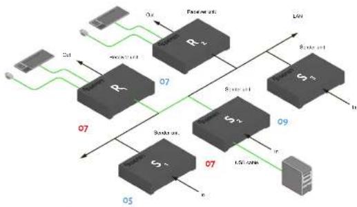
- Press and hold the CH + USB button on the desired Receiver unit, for at least two seconds.
- The message 'Starting USB' will appear on the connected display.
Figure 2.11 - Receiver unit Rt has USB control.
flowchart
graph TD
    A["Router R"] -->|07| B["Switch S"]
    B -->|05| C["Server"]
    D["Router R"] -->|07| E["Switch S"]
    E -->|09| F["Server"]
    G["Router R"] -->|07| H["Switch S"]
    H -->|07| I["Server"]
    J["Router R"] -->|07| K["Switch S"]
    K -->|07| L["Server"]
    M["Router R"] -->|07| N["Switch S"]
    N -->|07| O["Server"]
    P["Router R"] -->|07| Q["Switch S"]
    Q -->|07| R["Server"]
    S["Router R"] -->|07| T["Switch S"]
    T -->|07| U["Server"]
    V["Router R"] -->|07| W["Switch S"]
    W -->|07| X["Server"]
    Y["Router R"] -->|07| Z["Switch S"]
    Z -->|07| AA["Server"]
    AB["Router R"] -->|07| AC["Switch S"]
    AC -->|07| AD["Server"]
    AE["Router R"] -->|07| AF["Switch S"]
    AF -->|07| AG["Server"]
Important
If switching between Active per request mode and Active on link mode, the Apply and Reboot buttons must be clicked to apply changes.
- In order to assign USB control to a different Receiver unit, repeat steps 1-2.
USB Control
Active on link mode
Under Active on link mode, a maximum of four USB devices can be used within a system. In the diagram, on the previous page, the system is already using the maximum number of USB devices (≥ USB devices per Receiver). If we had two more Receiver units (making a total of four Receiver units), we would only be able to connect one USB device to each Receiver unit. To switch to Active on link mode, follow the instruction below.
- Access the Web interface for the Sender unit.
- Login as "Administrator".
- Click the Functions tab
- Locate the USB over IP group and make sure the Enable USB over IP box is checked. This is the default setting.
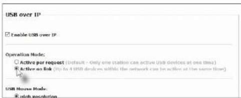
- Click the Active on link radio button within the USB over IP group.
- Click the Apply button within the USB over IP group.
- The following message will be displayed, at the top of the page, indicating that the new Serial over IP options have been applied.
Success: New USB options applied.
- Click the Reboot button at the bottom of the page. If the Reboot button is not clicked, the following message will be displayed, indicating that the unit must be rebooted.
Audio Connections
Audio works in both unicast and multicast modes. The only difference between the two modes is that the Line In port is automatically disabled, on all Receiver units, in multicast mode. To illustrate how audio works with the Gefen AV over IP Senders and Receivers, we will set up a microphone and some speakers.
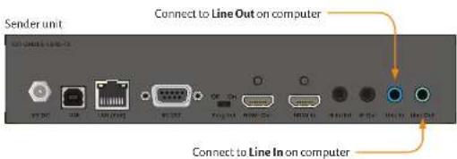
- Connect a 3.5mm mini-stereo cable from the Line In port on the Sender unit to the Line Out port on the computer.
Note
On HDMI and DisplayPort™ Senders, when a cable is connected to the Line In port on the Sender unit, it takes priority over and replaces the audio from the video input. The audio will be heard on the HDMI or DisplayPort™ Out, Line Out, and Opt Out ports on the Receiver unit.
- Connect another 3.5mm mini-stereo cable to from the Line Out port on the Sender unit to the Line In port on the computer.
- Connect a 3.5mm mini-stereo cable from the Mic In port on the Receiver to the output of a microphone pre-amp or other "Line Level" audio source.
Important
Some microphones may require a pre-amp connected inline to be compatible. Alternately, you can use a USB mic connected to one of the USB 2.0 ports on the Receiver.
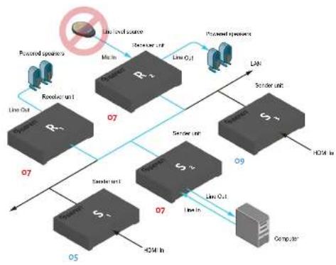
Connect to "line-level" source
Audio Connections
- Connect the Line Out port to powered speakers or a pair of headphones.
- Connect a Gefen CAB-TLINK-6MM TOSLINK cable from the Opt Out port to the Optical Digital Input of an AV receiver or amplifier.
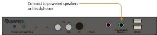
Receiver unit
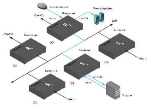
In the diagram below, the mouse and keyboard USB devices have been removed from Sender unit S2 and Receiver unit R2, for purposes of clarity. Arrowheads indicate the audio signal path.
Figure 2.12 - Audio connections in unicast mode.
flowchart
graph TD
    A["Router R1"] -->|Line out| B["Switch S2"]
    B -->|Line out| C["Computer"]
    D["Switch S3"] -->|Line out| E["Switch S4"]
    E -->|Line out| F["Computer"]
    G["Router R2"] -->|Line out| H["Switch S5"]
    H -->|Line out| I["Computer"]
    J["Switch S6"] -->|Line out| K["Switch S7"]
    K -->|Line out| L["Computer"]
    M["Powered speakers"] --> N["LAN"]
    O["Video Out"] --> P["Line out source"]
    Q["Video In"] --> R["Line in"]
    S["Video In"] --> T["Line in"]
    U["Video In"] --> V["Line in"]
    W["Video In"] --> X["Line in"]
    Y["07"] --> Z["09"]
    style A fill:#f9f,stroke:#333
    style D fill:#f9f,stroke:#333
    style G fill:#f9f,stroke:#333
    style O fill:#f9f,stroke:#333
    style J fill:#f9f,stroke:#333
    style K fill:#f9f,stroke:#333
    style L fill:#f9f,stroke:#333
    style M fill:#f9f,stroke:#333
    style N fill:#f9f,stroke:#333
    style O fill:#f9f,stroke:#333
    style P fill:#f9f,stroke:#333
    style Q fill:#f9f,stroke:#333
    style R fill:#f9f,stroke:#333
    style S fill:#f9f,stroke:#333
    style T fill:#f9f,stroke:#333
    style U fill:#f9f,stroke:#333
    style V fill:#f9f,stroke:#333
Audio Connections
Figure 2.13 - The Line In port, on all Receiver units, is automatically disabled in multicast mode.
flowchart
graph TD
    A["Router R1"] -->|Line Out| B["Switch S1"]
    A -->|Line Out| C["Switch S2"]
    D["Router R2"] -->|MAC In| E["Switch S3"]
    D -->|MAC In| F["Switch S4"]
    G["Computer"] -->|Line Out| H["Switch S5"]
    G -->|Line Out| I["Switch S6"]
    J["Powered opacers"] --> K["Line Level source"]
    L["Processed opacers"] --> M["Line O2"]
    N["LAN"] --> O["Switch S7"]
    P["HDMI In"] --> Q["Switch S8"]
    R["Computer"] --> S["Switch S9"]
Audio Sources and De-Embedding
The following outlines the audio de-embedding functionality of this product.
If a 3.5mm mini-stereo cable is connected to the Line In port on the HDMI or DisplayPort™ Sender unit, then the HDMI or DisplayPort™ audio will be disabled on the Receiver unit. The Line Out port, on the Receiver unit, will output audio from the source connected to the Line In port on the Sender unit.
When a source is connected to the Line In port on the Sender unit, the audio will be heard on the HDMI Out or DisplayPort™ Out, Line Out, Opt Out, and Coax Out ports.
The Line In port on the Receiver unit will only pass audio to the Line Out port on the Sender unit when in unicast mode.
- The Opt Out port will de-embed both 2-channel PCM and Bitstream (up to 5.1 channel) audio from the HDMI In or DisplayPort™ In port. High-resolution (lossless)
Creating Video Walls
The web interface facilitates the creation of video walls up to 16 horizontal and 16 vertical displays. Video walls may contain any number or rows and columns and any combination of these can be enabled, as necessary.
Wall Size and Layout
- Access the Web interface for the Receiver unit.
- Login as "Administrator" or "User".
- Make sure that the Enable Video Wall option is enabled under the Functions tab of the Sender unit, then click the Video Wall tab. Click the Apply button.
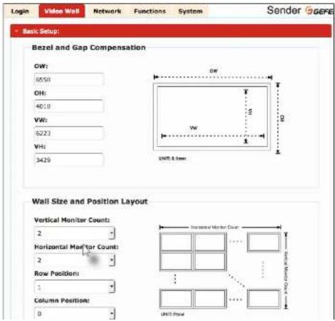
4 Under Bezel and Gap Compensation, specify the Outside Width (OW), Outside Height (OH), Video Width (VW), and Video Height (VH) fields.
Creating Video Walls
- Under the Wall Size and Position Layout window group, click the drop-down lists for the Vertical Monitor Count and Horizontal Monitor Count and select the number of rows and columns of displays, respectively.
- Select the row and column positions using the Row Position and Column Position drop-down lists. Both row and column positions begin with a reference value of zero.
- Click the drop-down list, next to the Apply button, to select the desired host or client to which these settings will be applied.
If the All option is selected, then all parameters will be transferred to all Receiver units. For monitor count and bezel compensation in a video wall array of matching displays, this is fine, but the row and position will also be copied. There is an option for "This" unit that will apply to the current unit being interfaced with. The "This" option can be used to precisely set the proper position of each unit but would require the user to access the web interface of each unit to set. Alternatively, the drop-down will provide a list of all connected host (Sender units) and clients (Receiver units). This process allows the configuration of an entire video wall from a single unit.
Creating Video Walls
Bezel Compensation
Display devices have a region where video data is not displayed. This area is called the bezel. Bezel compensation takes this area into account when a single video source is mapped across multiple displays. It is recommended, when a video wall is set up for the first time, that bezel compensation values be set to zero. Bezel compensation can be adjusted at any time.
The illustration on the left shows a 2x2 video wall without bezel compensation. Note how the circle is stretched, slightly, horizontally. On the right, bezel compensation is used to correct the "distorted" image.


-
Access the Web interface for the Sender unit.
-
Login as "Administrator" or "User".
-
Click the Video Wall tab.
-
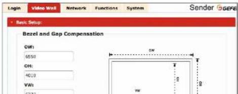
Adjust the values under the Bezel and Gap Compensation window group. Refer to the diagram, to the right of each field, to see the effect of each value. All entered values are applied to the physical displays in 0.1 millimeter increments.
Setting the Video Mode
The video mode can be changed using the Mode button or through the Web interface of the Sender unit. Consecutively pressing the Mode button on the Sender unit will switch between Graphic and Video mode.
Using the Web interface
- Access the Web interface for the Sender unit.
z. Login as "Administrator" or "User". - Click the Network tab.
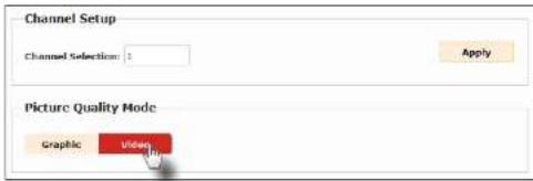
4 Click the desired mode within the Picture Quality Mode window group. The default setting is "Video".
▶ Video Mode
If the video signal is motion video, then click the Video button. This mode will optimize the frame rate.
▶ GraphicMode
If the video signal is a static image, then click the Graphic button.
- The selected mode will be displayed on the screen, as shown below.

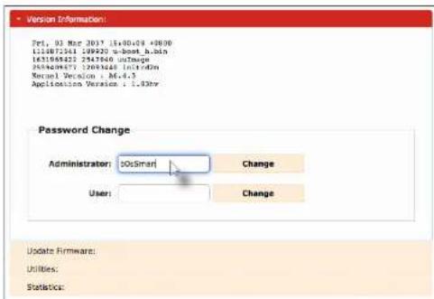
Changing the Password
- Access the Web interface for the Sender / Receiver unit
- Login as "Administrator".
- Click the System tab.
- Under the Password Change window group, enter the new password for the desired username. Note that the new password will not be masked when it is entered.
- Click the Change button.
Utilities
Reset using the Web Interface
All Senders and Receivers can be reset using the web interface or using the buttons on the front panel. When using the Web interface, the Sender / Receiver units will automatically be reset to Auto IP mode. When using the front-panel buttons, the Sender / Receiver can be reset to either Auto IP or Static IP mode.
Note
Once a unit has been reset to Auto IP mode, the connection to the Web interface will be terminated. To reestablish a connection to the Web interface, from your computer, see Installation (page 17).
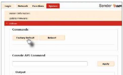
- Access the Web interface for the desired Sender / Receiver unit. It does not matter which unit is reset first.
- Login as "Administrator".
- Click the System tab.
- Click the Utilities rollout.
- Click the Factory Default button.
Utilities
- Both the Power and Link LED indicators will begin to flash.
Receiver unit (shown)

- After both LED indicators stop flashing, the unit will be reset.
- Repeat the process for each unit.
Utilities
Reboot using the Web Interface
The Sender and Receiver units can be rebooted in three different ways: Using the Web interface, the Reset button on the front panel, or simply disconnecting and reconnecting the power.
- Access the Web interface for the Sender / Receiver unit.
- Login as "Administrator".
- Click the System tab.
- Click the Utilities rollout.
- Click the Reboot button.
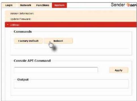
- After a few moments, the Power LED indicator will flash.
- Several seconds later, the Power LED indicator will glow solid blue and the Link LED
Utilities
Reboot using the Web Interface
The Sender and Receiver units can be rebooted in three different ways: Using the Web interface, the Reset button on the front panel, or simply disconnecting and reconnecting the power.
- Access the Web interface for the Sender / Receiver unit.
- Login as "Administrator".
- Click the System tab.
- Click the Utilities rollout.
- Click the Reboot button.
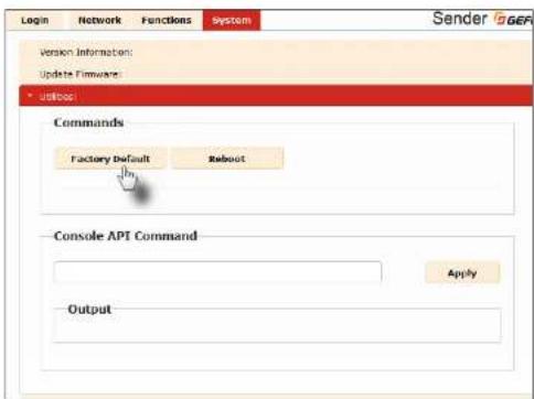
- After a few moments, the Power LED indicator will flash.
Utilities
Reboot using the Front Panel
- Press the Reset button, on the desired Sender or Receiver unit, using the end of a paper clip or other sharp pointed object.
- After a few moments, the Power LED indicator will flash.
- Several seconds later, the Power LED indicator will glow solid blue and the Link LED indicator will begin to flash
- After both LED indicators stop flashing, the reboot process will be complete.
Telnet Access
Note
By default, the Telnet login credentials are disabled. This setting is required when using the Matrix controller (Gelen part no. EXT-CU-IAN) but can be enabled for security purposes. Use the #use_Telnet_login command to enable or disable this feature.
- Launch the desired terminal application (e.g. Windows Hyperterminal, etc).
- Within the terminal program, enter the IP address of the Sender or Receiver unit that you wish to control.
- Enter the TCP listening port. The default listening port is 23.
4 After the correct settings have been used in the terminal program, information similar to the following will be displayed.
In the example, below, we are connected to the client (Receiver unit) and Telnet login has been enabled:
---- Welcome to the GoEn Telnet Server ----
as-2-clientGOIC9103C883 login;
- Login as "Administrator". The default password is "admin". To change the Telnet password, see the #set_telnet_pass command.
- Type the help for a list of commands or refer to the tables on the following pages.
Commands
Important
Commands that are limited to a Sender or Receiver unit are marked as "Tx only" and "Rx only", respectively. Unless otherwise noted, commands can be used when connected to either a Sender or Receiver unit.
Discovery Service
| Command Description | |
| fact_device_dose | Displays the device description |
| fact_discovery | Displays the current state of the discovery service |
| fact_discovery_mode | Displays the discovery read/write mode |
| fact_showme | Displays the status of the showme state |
| fact_device_dose | Sets the device description |
| fact_discovery | Enables or disables the discovery service |
| fact_discovery_mode | Sets the discovery mode |
| fact_showme | Enables or disables the "show me" feature |
Help
| Command Description | |
| #be1p | Displays a list of available commands |
Network
| Command Description | |
| #get_gateway | Displays the gateway IP address |
| #get_ip_address | Displays the IP address |
| #get_ip_mode | Displays the IP mode |
| #get_ip认证 | Displays the IP configuration information |
| #get_ip_mode | Displays the network casting mode |
| #get_network | Displays the subnet mask address |
- 2023年1月1日
Commands
Command Description
| #get_telnet_login | Displays the status of the Telnet login |
| #get_telnet_port | Displays the Telnet listening port |
| #get_telnet_welcome | Displays the Telnet welcome message |
| #get_udp_access | Displays the UDP access state |
| #get开采_port | Displays the UDP listening port |
| #get_web_port | Displays the HTTP listening port |
| #act_gateway | Sets the gateway address |
| #auth_ip_address | Sets the IP address |
| #act_ip_node | Sets the IP mode |
| #act_not_mode | Sets the network casting mode |
| #act_netmask | Sets the subnet mask address |
| #act_remote_udp_access | Enables or disables remote UDP access |
| #auth_remote_udp_ip | Sets the remote UDP IP address |
| #auth_remote_udp_port | Sets the remote UDP listening port |
| #act_telnet_access | Enables or disables Telnet access |
| #act_telnet_login | Enables or disables the Telnet login |
| #act_telnet_pass | Sets the Telnet password |
| #act_telnet_port | Sets the Telnet listening port |
| #auth_telnet_welcome | Sets the Telnet welcome message |
| #auth_udp_access | Enables or disables UDP access |
| #act_add_port | Sets the UDP listening port |
| #act_web_port | Sets the HTTP listening port |
Routing
| Command Description | |
| Get\_zx\_channel | Displays the channel of the Receiver unit (Rx only) |
| Get\_v | Displays the current video input status |
| Request\_usb | Requests USB control when active per request is |
Commands
RX Specific
| #get_clk_lock | Displays the audio clock lock |
| #get_edid_copy | Displays the EDID copy state (Rx only) |
| #get_mask | Displays the current video mask state |
| #get_x_d | Displays the ID of the Receiver unit |
| #get_ww | Displays the status of the video wall |
| #get_ww_bo | Displays the video wall bezel compensation |
| #get_ww_delay | Displays the video wall display delay |
| #get_ww_hscale | Displays the video wall horizontal up-scaling |
| #get_ww_layout | Displays the video wall horizontal and vertical maximum display count |
| #get_ww_osd | Displays the status of the video wall OSD |
| #get_ww_pos | Displays the video wall display position |
| #get_ww_shift | Displays the video wall display shift |
| #get_ww_vscale | Displays the video wall vertical up-scaling |
| #net_clk_lock | Sets the audio clock lock |
| #act_oid_copy | Enables or disables EDID copy |
| #act_mask | Enables or disables video masking |
| #act_ox_id | Sets the ID of the Receiver unit |
| #act_ww | Enable / disable video wall |
| #net_ww_ku | Sets the video wall bezel compensation |
| #net_ww_delay | Sets the video wall display delay |
| #act_ww_hscale | Displays the video wall horizontal up-scaling |
| #act_ww_layout | Sets the video wall horizontal and vertical maximum display count |
| #set_ww_osd | Enable / disable the video wall OSD |
| #net_ww_pos | Sets the video wall display position |
| #act_ww_shift | Sets the video wall display shift |
| #act_ww_vscale | Displays the video wall vertical up-scaling |
Commands
Serial
| Command Description | |
| #get_serial_a_low | Displays the Serial-over-IP state |
| #get_serial_band | Displays the serial baud rate setting |
| #get_serial_bits | Displays the serial data bits setting |
| #get_serial_parity | Displays the serial parity setting |
| #get serial stop | Displays the serial stop bits setting |
| Fact_serial_a_low | Enables or disables Serial-over-IP mode |
| Fact_serial_band | Sets the baud rate for the serial port |
| fact_serial_bits | Sets the data bits for the serial port |
| fact_serial_parity | Sets the parity setting for the serial port |
| fact_serial_stop | Sets the number of stop bits for the serial port |
System
| Command Description | |
| #get_firmware_version | Displays the firmware version |
| #factory_reset | Resets the unit to factory-default settings |
| #fw_upgrade | Upgrades firmware using external file |
| #rcboot | Reboots the unit |
TX Specific
| Command Description | |
| fgct_block | Displays the current video blocking state |
| fgct_sdep | Displays the HDCP state |
| fgct_pq_mode | Displays the picture quality mode |
| fgct_tx_channel | Displays the video channel |
| fgct_block | Enables or disables video blocking |
| fgct_sdep_allow | Enables or disables HDCP detection |
Commands
USB
| Command Description | |
| #get_nab_allow | Displays the USB-over-IP state |
| #get_nab_mode | Displays the USB operating mode |
| #mfk_nab_mode | Displays the mouse operating mode |
| #mfk_nab_allow | Enables/disables USB over IP |
| #fect_nab_mode | Sets the USB operating mode |
| #fect_nab_mode | Sets the USB mouse mode |
Video
| Command Description | |
| #get_video_allow | Displays the Video-over-IP state |
| #sec_video_allow | Sets the Video-over-IP state |
Web Interface
| Command Description | |
| Fact_wobui_ad_pass | Sets the administrator password for the web UI |
| Fact_wobui_user_pass | Sets the user password for the web UI |
Commands
#help
Displays a list of available commands. The commands listed are specific to either the Sender or Receiver unit.
Syntax
help
Parameters
None
Example
help
HELP
FACTORY_RESET
FW UPGRADE
GET BLOCK
GET CLK LOCK
GET DEVICE DESC
GET DISCOVERY
GET DISCOVERY MODE
GET EDID COPY
GET_FIRMWARE_VERSION
| GET GATEWAY
| GET_HDCF
GET IP ADDRESS
GET IP MODE
GET IPCONFIG
GET MASK
GET NET MODE
GET_NETMASK
GET PQ MODE
Commands
#factory\_reset
Resets the unit to factory-default settings. perm must be included and set to 1.
Syntax
|factory_resetparaml
Parameters
param1 Integer 1
Example
*factory_reset 1 RESET TO FACTORY DEFAULTS
Related Commands
rcboot
Commands
#fw\_upgrade
Upgrades the firmware from the command.
Syntax
|fw_upgrade filename
Parameters
filename
String
Example
fw_upgrade firmware_file_v2.bin
Commands
#get\_block
Displays the current video blocking state. This command is only available when connected to a Sender unit. To enable or disable the video blocking state, refer to the #act_block command.
Syntax
get_block
Parameters
None
Example
get block BLOCK DISABLED
Related Commands
oct_mask
set_block
Commands
#get\_clk\_lock
Displays the audio clock lock.
Syntax
Iget_clk_lock
Parameters
None
Example
get clk lock
CLK_LOCK 0
Related Commands
set clk lock
Commands
#get\_device\_desc
Displays the description of the Sender / Receiver unit.
Syntax
get_device_desc
Parameters
None
Example
get device desc
DEVICE DESCRIPTION IS Genius Sender 2
Related Commands
set device dose
Commands
#get\_discovery
Displays the current discovery mode setting.
Syntax
|get_discovery
Parameters
None
Example
get_discovery
DISCOVERY SERVICE SET TO ENABLED
Related Commands
fset_discovery
set showme
Commands
#get\_discovery\_mode
Displays the current discovery mode setting.
Syntax
get_discovery_mode
Parameters
None
Example
get_discovery_mode
DISCOVERY MODE 1
Related Commands
fuel discovery
+rel. discovery mode
set showmo
Commands
#get\_edid\_copy
Displays the EDID copy state. This command is only available when connected to a Receiver unit.
Syntax
get_edid_copy
Parameters
None
Example
get_edid_copy
COPY FDTD OF CONNECTED DISPLAY IS ENABLED
Related Commands
sct_odid_copy
Commands
#get\_firmware\_version
Displays the firmware version.
Syntax
get_firmware_version
Parameters
None
Example
get firmware version
FIRMWARE VERSION IS 1.83hv
Related Commands
fw_upgrade
Commands
#get\_gateway
Displays the gateway address of the Sender/Receiver unit.
Syntax
get_gateway
Parameters
None
Example
get_gateway
GATEWAY: 192.168.0.1
Related Commands
feel to address
fget. To mode
+gel: pacific
fcel_netmask
The
feel_to_address
fset ip mode
set notmask
Commands
#get\_hdcp
Displays the current HDCP state. This command is only available when connected to a Sender unit.
Syntax
get_hdcp
Parameters
None
Example
get_hdcp
HDCF ENCRYPTED SOURCE IS ENABLE
Related Commands
sct_hdcp_allow
Commands
#get\_ip\_address
Displays the current IP address of the Sender or Receiver unit.
Syntax
|get_ip_address
Parameters
None
Example
get_ip_address
IP: 10.5.64.60
Related Commands
fgel_galeway
†qel. i o made
†qel. i pcnfiq
cel_nel_mask
feel. web port.
The Galway
+sel i o address
set in mode
†set netmask
set_web_port
Commands
get_ip_mode
Displays the current IP mode.
Syntax
|get_ip_mode
Parameters
None
Example
get_ip_mode
IF MODE IS SET TO DHCP
Related Commands
fcel_galeway
+cel. i o address
†qel. i pcnfiq
cel_netmask
file web port.
The Galway
+sel i o address
set in mode
‡set netmask
set web port
Commands
#get\_ipconfig
Displays the current IP configuration. In addition to providing the MAC address and the broadcast IP address, this command also provides the same information as executing the #get_ip_mode, #get_ip_address, #get_netmask, and #get_gateway commands.
Syntax
get_ipconfig
Parameters
None
Example
get ipconfig
Displays the current video mask state. This command is only available when connected to a Receiver unit. To enable or disable video masking on a Receiver unit, refer to the #so t mask command.
Syntax
get_mask
Parameters
None
Example
get mask MASK DISABLED
Related Commands
get_block
set_mask
Commands
#get\_net\_mode
Displays the current network mode setting.
Syntax
|get_net_mode
Parameters
None
Example
get net mode
NETWORK MODE SET TO MULTICAST
Related Commands
set not mode
Commands
#get\_netmask
Displays the current net mask setting.
Syntax
| get_netmask
Parameters
None
Example
get_netmask
NETMASK: 255.255.255.0
Related Commands
qcel_qaleway
qcel_ip_address
qcel_lncnfiq
qcel_web_port
set_qaleway
set_ip_address
set_ip_node
set notmask
set_web_port
Commands
#get\_pq\_mode
Displays the picture quality mode. This command is only available when connected to a Sender unit.
Syntax
get_pg_mode
Parameters
None
Example
get_pq_mode
TRANSMITTERR PICTURE QUALITY TS VIDEO
Related Commands
sct_pq_mode
Commands
#get\_remote\_udp\_access
Displays the remote UDP access state
Syntax
get_remote_uop_access
Parameters
None
Example
get remote udp access
REMOTE UDP ACCESS IS ENABLED
Related Commands
file remote udp ip
+qel remote urip por..
†qel. udp access
cel_udp_port.
fuel remote udp access
sel._remote_udp_ip
+sel remote udp por.
+sel. udp access
‡set udp port
Commands
get_remote_udp_ip
Displays the remote UDP IP address.
Syntax
get_remote_udp_ip
Parameters
None
Example
get remote udp access
REMOTE UDP IP: 192.168.1.29
Related Commands
file remote udp access
+qeloremle urip por..
‡gel. udp access
cel_udp_port.
fuel remote udp access
sel._remote_udp_ip
+sel remote udp por.
+sel. udp access
+se1. udp port
Commands
#get\_remote\_udp\_port
Displays the remote UDP listening port.
Syntax
get_remote_uop_port
Parameters
None
Example
get_remote_udp_port
REMOTE UDP COMMUNICATIONS PORT: 50008
Related Commands
file remote udp access
+qel._remote_udp_ip
†qel. udp access
cel_udp_port.
5.1. remite urip access
set_remote_udp_ip
+sel remote udp por.
+rel. udp access
+se1_udp_port
Commands
#get\_rx\_channel
Displays the current channel of the Receiver unit. To set the video channel of a Receiver unit, use the x command
Syntax
get rx channel
Parameters
None
Example
get_rx_channel RECEIVER CHANNEL: 1
Related Commands
get tx channel
set tx channel
Commands
#get\_rx\_id
Displays the ID of the Receiver unit. This command is only available when connected to a Receiver unit.
Syntax
get_rx_id
Parameters
None
Example
get_rx_id RX ID: 8
Related Commands
set rx id
Commands
#get\_serial\_allow
Displays the Serial-over-IP state. Use the #set serial allow command to enable or disable the Serial-over-IP feature.
Syntax
get serial allow
Parameters
None
Example
get_serial_allow
SERIAL OVER IP is ENABLE
Related Commands
get serial baud
gct serial parity
get serial stop
sct serial allow
sct serial baud
set serial bits
sct serial parity
set serial stop
Commands
#get\_serial\_baud
Displays the serial baud rate setting. Use the #set serial baud command to set the baud rate.
Syntax
get serial baud
Parameters
None
Example
get_serial_baud
SERIAL BAUD RATE TS 19200
Related Commands
get serial allow
get serial bits
get serial parity test partial
get serial stop
set serial allow
set serial baud
set serial bits
set serial parity
set serial stop
Commands
#get\_serial\_bits
Displays the serial data bits setting. Use the #set serial bits command to set the number of data bits.
Syntax
get serial bits
Parameters
None
Example
get_serial_bits
SERIAL DATA BITS 75 8
Related Commands
get serial allow
gct serial baud
get serial parity
gct serial stop
sct serial allow
set serial baud
sct serial bits
set serial parity
sct serial_stop
Commands
#get\_serial\_parity
Displays the serial parity bit setting. Use the tset serial parity command to set the parity bit
Syntax
get serial parity
Parameters
None
Example
get_serial_parity
SERIAL PARTY MODE SET TO NONE
Related Commands
get serial alloy
get serial baud
get serial bits
get serial stop
set serial allow
fset serial baud
set serial bits
4.15 Series part
+set_sorial_stop
Commands
#get\_serial\_stop
Displays the serial stop bits setting. Use the #set serial stop command to set the number of stop bits.
Syntax
get serial stop
Parameters
None
Example
#get_serial_stop
SERIAL, STOP BITS TS 1
Related Commands
#get serial allow
#gct serial baud
#get serial bits
#gct serial parity
#sct serial allow
#set serial baud
#sct serial bits
#set serial parity
#sct serial_stop
Commands
#get\_showme
Displays the showme state.
Syntax
| get_showme
Parameters
None
Example
get showme
SHOW ME DISABLED
Related Commands
set showmo
Commands
#get\_telnet\_access
Displays the Telnet access state. Use the #set telnet access command to enable or disable Telnet access.
Syntax
get_telnet_access
Parameters
None
Example
get_telnet_access
TELNET ACCESS IS ENABLED
Related Commands
get telnet login
gct telnet port
get telnet welcome
sct telnet access
sct tolnet pass
set telnet login
sct tolnet pass
set telnet port
sct tolnet welcome
Commands
#get\_telnet\_login
Displays the Telnet login status
Syntax
get_telnet_login
Parameters
None
Example
get_telnet_login
TELNET LOGIN SET TO DISABLED
Related Commands
fget_lnet_access
†qel. I.eIrel. port.
get. I.e!rel. we!come
+sel, telnet, access
sel. 1elnel. pass
sel_1elnet_1ogir
+sel, I.eIrel, pass
+sel. telnet. port.
fuel, I.e!nel, we!come
Commands
#get\_telnet\_port
Displays the Telnet listening port.
Syntax
get_telnet_port
Parameters
None
Example
get_telnet_port
TELNET COMMUNICATION PORT: 23
Related Commands
fget_lnet_access
fcel. telnet. lugin
†cel. I.e!nel. welcome
+sel, telnet, access
sel. 1elnel. pass
set_letnet_login
+sel. I.e1rel. pass
‡sel. lelnel. port.
fuel, I.eI net, welcome
Commands
#get\_telnet\_welcome
Displays the Telnet welcome message. Use the #set telnet welcome to create a custom welcome message.
Syntax
get_telnet_welcome
Parameters
None
Example
get_telnet_welcome
TELNET WELCOME SCREEN TS DTSARLED
Related Commands
get telnet access
get telnet login
†get telnet port
set telnet access
set telnet pass
set telnet login
set telnet pass
set telnet port
Commands
#get\_tx\_channel
Displays the video channel of the Sender unit. This command is only available when connected to a Sender unit.
Syntax
get_tx_channel
Parameters
None
Example
get_tx_channel
TRANSMITTER CHANNEL: 1
Related Commands
get rx channel
sct_tx_channel
r
Commands
#get\_udp\_access
Displays the UDP access state. Use the first UDP access command to enable or disable UDP access.
Syntax
get udp access
Parameters
None
Example
get_udp_access
102 ACCESS IS ENABLE
Related Commands
get remote http access
get remote udp ip
fget remote up port
get udp port
set remote udp access
fset remote uap ip
set remote uap port
set udp port
Commands
#get\_udp\_port
Displays the local UDP listening port.
Syntax
|get_udp_port
Parameters
None
Example
get_udp_port
UDP PORT SET TO 50007
Related Commands
ftcel_remote_udp_access
+gel remote udp ip
†gel. remote urip por
+cel_udp_access
fuel remote udp access
sel._remote_udp_ip
+sel remote udp por.
+rel. udp access
‡set udp port
Commands
get_usb_allow
Displays the USB-over-IP state.
Syntax
|get_usb_allow
Parameters
None
Example
get_usb_allow
USB OVER IP is ENABLE
Related Commands
†qel_usb_mode †qel_usb_mouse †set.usb_allow †set.usb_mode †set.usb_mouse
Commands
get_usb_mode
Displays the USB operating mode.
Syntax
| get_usb_mode
Parameters
None
Example
get usb mode
USB OPERATION MODE IS ACTIVE PER REQUEST
Related Commands
feel usb allow
feel usb mouse
+set usb allow
+sel usb mode
set usb mouse
Commands
#get\_usb\_mouse
Displays the mouse operating mode
Syntax
get usb mouse
Parameters
None
Example
get usb mouse
USB MOUSE MODE IS HIGH RESOLUTION
Related Commands
feel usb allow
+gel usb mode
+sel usb allow
+sel usb mode
set usb mouse
Commands
This page has been intentionally left blank
Commands
#get\_video\_allow
Displays the Video-over-IP status. Use the #set video allow command to enable or disable video over IP.
Syntax
get video allow
Parameters
None
Example
get_video_allow
VIDEO OVER TP is ENABLE
Related Commands
sct_video_allow
Commands
#get\_vw
Displays the video wall enable/disable setting
Syntax
I get vw
Parameters
None
Example
get vw
VN O
Related Commands
feel vs bn
fuel vs delay
+gel va houale
fcel va layout
feel we and
fcel, 28 pas
feel va shi
+cel vs vncale
+seL v8
+re|wbu
+ref. var. inday
+
(1) 2017年1月1日
-
-
-
-
-
-
-
-
-
-
-
-
-
-
-
-
-
-
-
-
-
-
-
-
-
-
-
-
-
-
-
-
-
-
-
-
-
-
-
-
-
-
-
-
-
-
-
-
-
-
-
-
-
-
-
-
-
-
-
-
-
-
-
-
-
-
-
-
-
-
-
-
-
-
-
-
-
-
-
-
-
-
-
-
-
-
-
-
-
- 91.
-
-
-
-
-
-
-
-
-
-
-
-
-
-
-
-
-
-
-
-
-
-
-
-
-
-
-
-
-
-
-
-
-
-
-
-
-
-
-
-
-
-
-
-
-
-
-
-
-
-
-
-
-
-
-
-
-
-
-
-
-
-
-
-
-
-
-
-
-
-
-
-
-
-
-
-
-
-
-
-
-
-
-
-
-
-
-
-
1.2.1. 2.3.1.
The text in the source image is illegible due to extreme pixelation and distortion. No characters, numbers, or symbols can be reliably extracted. Therefore, no OCR output can be generated that matches the visual content of the source image.
+seL_va_sh
4.1.1
Commands
#get\_vw\_bc
Displays the video wall bezel compensation setting.
Syntax
I get vw bc
Parameters
None
Example
# get_vw_bc VW_BC 6223 6550 3429 4010
Related Commands
tel_vz Liu tel_vz delay tel_vz huatale tel_vz_layout tel_vz und tel_vz pos tel_vz shi'l. tel_vz vatale tel_vz tel_vz bu tel_vz delay tel_vz huatale tel_vz layout tel_vz und tel_vz pos tel_vz shi'l.
Commands
#get\_vw\_delay
Displays the video wall delay setting.
Syntax
I get vw delay
Parameters
None
Example
*get_vw_delay VN_DELAY 0
Related Commands
cet_vw_bc
cet_vw_delay
cet_vw_hscale
cet_vw_layout
cet_vw_csd
cet_vw_pos
cet_vw_shitt
cet_vw_vscale
set_vw
set_vw_bc
set_vw_delay
set_vw_hscale
set_vw_layout
set_vw_csd
set_vw_pos
set_vw_shift
set_vw_vscale
Commands
#get\_vw\_hscale
Displays the video wall horizontal upscaling value.
Syntax
get vw bc
Parameters
None
Example
get_vw_bc
VW_HSCALE 0
Related Commands
tqel_va_bu tqel_va_delay tqel_va_husale tqel_va_layout tqel_va_nsd tqel_va_pos tqel_va_xhifi_l tqel_va_vusale tsei_va tsei_va_bu tsei_va_delay tsei_va_husale tsei_va_layout tsei_va_nsd tsei_va_pos tsei_va_xhifi_l
Commands
#get\_vw\_layout
Displays the video wall horizontal and vertical display count.
Syntax
I get vw layout
Parameters
None
Example
get vw layout
VN LAYOUT 2 2
Related Commands
fget va be
+get_vw_delay
Jcet va hscale
get_ww_layout
get_ww_osd
Icet va pa
get vw shift
get vw vscale
4set vw
fset_ww_bc
fset_vw_delay
+set_98_hscale
Aset_ww_layout
+set_ww_csd
Aset va pos
fset va shi t.
fuel_vw_vscale
Commands
#get\_vw\_osd
Displays the enable / disable status of the video wall OSD.
Syntax
get vw osd
Parameters
None
Example
get vw osd
VN_CSD 0
Related Commands
feel vs bn
fuel vs delay
feel w houle
fcel va byouh
feel we and
fcel_28_pas
fcel va shi
+gei va vcaale
The image is too blurry to recognize any text content.
The
于Bet_2W_10814y
fuel vw houale
fuel way you!
TEEL 68 nsd
+sel va pin
+se1_78_sh-1.
1.2.3.1.1
Commands
#get\_vw\_pos
Displays the video wall display position
Syntax
get vw pos
Parameters
None
Example
get vw pos
VW_POS 0 0
Related Commands
fget va bc
Acet vw delay
Aet va hscale
Aget vw layout
det va osd
let vs pos
det vw ob1*
100+ 174 1602
get_vx_value
+ = E L - V W
fset_ww_Lc
fset_vw_delay
fset vw hscale
Aset vs layout
4set vw osd
Jset vw pos
4.51. yu xhi
a1 = 7a2 - 10a_3 + 8
The following table is a single column:
Commands
#get\_vw\_shift
Displays the video wall display shift.
Syntax
I get vw shift
Parameters
None
Example
get_vw_shift
VW_SHIFT 0 0 0 0
Related Commands
fcel_va_bu fcel_vw_delay fcel_vw_huate fcel_vw_layout fcel_vw_nsd fcel_vw_pos fcel_vw_shi71 fcel_vw_huate fcel_vw fcel_vw_bu fcel_vw_delay fcel_vw_huate fcel_vw_layout fcel_vw_nsd fcel_vw_pos fcel_vw_shi71
Commands
#get\_vw\_vscale
Displays the video wall vertical upscaling value.
Syntax
get vw vscale
Parameters
None
Example
get vw vscale
VN_VSCALE C
Related Commands
get va bc
Acet vw delay
Jcet va hscale
get vw layout
det yw osd
[Unreadable]
det vw ob1*
100+ 174 1602
det_vx_value
+ = E L - V W
fset_ww_Lc
fset_vw_delay
fset vw hscale
Aset vw layout
4set vw osd
Jset vw pos
4.01 - 6.0 xh ^1
^1
The following table is a duplicate of the previous table to be corrected.
Commands
#get\_web\_port
Displays the HTTP listening port. Use the tset web port command to set the HTTP listening port.
Syntax
get_web_port
Parameters
None
Example
get_web_port
WEB INTERFACE PORT: 80
Related Commands
get gateway
get ip address
get ipconfig
set gateway
set ip address
set ip_mode
set_notmask
set_web_port
Commands
#reboot
Reboots the Sender / Receiver unit.
Syntax
reboot
Parameters
None
Example
reboot
UNIT WILL REBOOT SHORTLY
Related Commands
factory_reset
Commands
#request\_usb
Requests USB control when ACTIVE PER REQUEST USB mode is set.
Syntax
|request_usb
Parameters
None
Example
request usb
REQUESTING USB FROM SENDER
Related Commands
set_usb_mode
Commands
#set\_block
Enables or disables video blocking at a Sender unit.
Syntax
|set_block pareml
Parameters
paraml Integer
[0 ... 1]
| param! Description | |
| 0 | Disabled |
| 1 | Enabled |
Example
set block 1
BLOCK ENABLED
Related Commands
steel block
+set mask
Commands
#set\_clk\_lock
Sets the audio clock lock. This command is only available on the Receiver unit. After executing this command, the unit must be rebooted to apply the changes.
Syntax
set_block_param1
Parameters
paraml Integer [o ... 500]
Example
set_clk_lock 100
PLEASE REBOOT THE UNIT TO APPLY CHANGES
Related Commands
get clk lock
Commands
#set\_device\_desc
Sets the description for the Sender / Receiver unit. The description string cannot exceed 30 characters in length. Spaces and underscore characters are acceptable. Avoid using symbols and special characters.
Syntax
set_description_param
Parameters
param1 String
Example
|set description Blu-ray Panasonic
PRODUCT DESCRIPTION SET
Related Commands
get_device_doso
Commands
#set\_discovery
Enables or disables the discovery feature. The default value is On.
Syntax
|set_discoveryparam|
Parameters
| param! Description | |
| 0 | Off |
| 1 | On |
Example
set_discovery 0
DISCOVERY SERVICE SET TO DISARIED
Related Commands
get discovery
+set showe
†cel showe
Commands
#set\_discovery\_mode
Sets the discovery read / write mode.
Syntax
|set_discovery_mode_param
Parameters
paraml Integer
[0 ... 1]
| param! Description | |
| 0 | Read only mode |
| 1 | Read / write mode |
Example
set_discovery_mode 1
DISCOVERY MODE
Related Commands
+get_edid_copy
Commands
#set\_edid\_copy
Enables or disables the EDID copy state. When parameter = 1, the downstream EDID (connected to the Receiver unit) is copied to the Sender unit. If parameter = 0, then the internal (default) EDID is used. This command is only available when connected to a Receiver unit. After executing this command, the unit must be rebooted to apply the changes.
Syntax
|set_edid_copy_param
Parameters
| param1 | Integer | [0 | ... | 1] |
| param1 Description | |
| 0 | Off |
| 1 | On |
Example
set_edid_copy_1 COPY FID OF CONNECTED DISPLAY SET TO ENABLED
PLEASE REBOOT THE UNIT TO APPLY CHANGES
Related Commands
get_edid_copy
Commands
#set\_gateway
Sets the gateway address. This command is only applicable when using Static IP mode. percent must be specified using dot-decimal notation. After executing this command, the unit must be rebooted to apply the changes.
Syntax
set_gateway paraaml
Parameters
param1 IP Address
Example
set gateway 192.168.1.1 CATEWAY ADDRESS SET TO 192.168.1.1 PLEASE REBOOT THE UNIT TO APPLY CHANGES
Related Commands
Aget_gateway Aget_ip_address Aget_ip_mode Aget_ipconfig Aget_notmask Aget_web_port Aset_ip_address Aset_ip_mode Aset_netmask fset_web_port
Commands
#set\_hdcp\_allow
Blocks or unblocks HDCP-encrypted sources. This command does not decrypt HDCP content and is only available when connected to a Sender unit. After executing this command, the unit must be rebooted to apply the changes.
Syntax
set_hdcp_allow param1
Parameters
| param1 | Integer | [0 | ... | 1] |
| param1 Description | |
| 0 | Disabled |
| 1 | Enabled |
Example
set hdcp allow 1
HDCF ENCRYPTED SOURCE SET TO ENABLED
PLEASE REBOOT THE UNIT TO APPLY CHANGES
Related Commands
get hdep allow
Commands
#set\_ip\_address
Sets the IP address, parameter must be specified using dot-decimal notation. After executing this command, the unit must be rebooted to apply the changes.
Syntax
set_ip_address param1
Parameters
param1 IP Address
Example
set_gateway 192.168.1.1 GATEWAY ADDRESS SET TO 192.168.1.1 PLEASE REBOOT THE UNIT TO APPLY CHANGES
Related Commands
get gateway
get ip address
get ip mode
get ipconfig
get notmask
get web port
set gateway
set_ip_mode
set_notmask
set_web_port
Commands
#set\_ip\_mode
Sets the IP mode. After executing this command, the unit must be rebooted to apply the changes.
Syntax
set_ip_mode_param1
Parameters
paraml Integer [0 ... 2]
| param: Description | |
| 0 | Static |
| 1 | DHCP |
| 2 | Auto IP |
Example
set ip mode 1
IF MODE SET TO DHCP
PLEASE REBOOT THE UNIT TO APPLY CHANGES
Related Commands
get_gateway
get ip address
ct ip mode
get ipconfig
get netmask
ect web port
set to address
Commands
#set\_mask
Enables or disables video masking at a Receiver unit.
Syntax
|set_mask param:
Parameters
paraml Integer
[0 ... 1]
| param! Description | |
| 0 | Disabled |
| 1 | Enabled |
Example
set mask 1
MASK ENABLED
Related Commands
steel mask
+set block
Commands
#set\_net\_mode
Sets the network casting mode.
Syntax
|set_net_mode_param
Parameters
paraml Integer [0 ... 1]
| param1 Description | |
| 0 | Unicast |
| 1 | Multicast |
Example
set net mode 0
NETWORK CASTING MODE SET TO UNICAST
Related Commands
get not mode
Commands
#set\_netmask
Sets the network mask address. param must be specified using dot-decimal notation. After executing this command, the unit must be rebooted to apply the changes.
Syntax
set_netmask_param1
Parameters
param1 IP Address
Example
set_netmask 255.255.255.0
NETMASK ADDRESS SET TO 255.255.255.0
PLEASE REBOOT THE UNIT TO APPLY CHANGES
Related Commands
get gateway
get ip address
†get ip mode
get ipconfig
get_netmask
get web port
set ip address
set ip node
set 15 mode
set gateway
+set_web_port
Commands
#set\_pq\_mode
Sets the picture quality mode. This command is only available when connected to a Sender unit.
Syntax
set_pg_mode param1
Parameters
paraml Integer [0 ... 1]
| param1 Description | |
| 0 | Graphic |
| 1 | Video |
Example
I set pg mode 1
TRANSMITTER PICTURE QUALITY SET TO VIDEO
Related Commands
get_pq_mode
Commands
#set\_remote\_udp\_access
Enables or disables remote UDP access. After executing this command, the unit must be rebooted to apply the changes.
Syntax
set remote udp access parami
Parameters
| paraml | Integer | [0 | ... | 1] |
| param1 Description | |
| 0 | Disabled |
| 1 | Enabled |
Example
set remote uop access 1
REMOTE UDP ACCESS SET TO ENABLED
PLEASE REBOOT THE UNIT TO APPLY CHANGES
Related Commands
cet_remote_udp_access
get_remote_udp_ip
get_remote_udp_port
get udp access
get_udp_port
set_remote_udp_access
+set_remote_udp_ip
Commands
#set\_remote\_udp\_ip
Set the remote UDP IP address. param must be specified using dot-decimal notation. After executing this command, the unit must be rebooted to apply the changes.
Syntax
#set remote udp ip param1
Parameters
param1 IP address
Example
#set_remote_udp_ip 192.168.1.29
REMOTE UDP IP ADDRESS SET TO 192.168.1.29
PLEASE REBOOT THE UNIT TO APPLY CHANGES
Related Commands
get remote udp access
get remote udp ip
#get remote udp port
fget_udp_access
#get_udp_port
#set remote udp access
#set remote udp port
fset udp access
set_udp_port
Commands
#set\_remote\_udp\_port
Set the remote UDP listening port. After executing this command, the unit must be rebooted to apply the changes.
Syntax
set_remote_udp_port_param1
Parameters
paraml Integer [0 ... 65535]
Example
set_remote_udp_port 50008
REMOTE UDE COMMUNICATIONS PORT IS SET TO PORT 50008 PLEASE REBOOT THE UNIT TO APPLY CHANGES
Related Commands
get remote udp access
get remote udp ip
get remote udp port
fget udp acces
fcet udp port
Aset remote udp access
4set remote upon in
- set, vdr, aagsee
- -
- 104 port-1.
Commands
#set\_rx\_id
Sets the ID of the Receiver unit. This command is only available when connected to a Receiver unit.
Syntax
set rx id param1
Parameters
paraml Integer [0 ... 65535]
Example
set_rx_id 1
RX ID: 1
Related Commands
gct_rx_id
Commands
#set\_serial\_allow
Enables or disables serial over IP. After executing this command, the unit must be rebooted to apply the changes.
Syntax
set serial allow param1
Parameters
| paraml | Integer | [0 | ... | 1] |
| param1 Description | |
| 0 | Disable |
| 1 | Enable |
Example
|set_serial_allow 0 SERIAL OVER IP SET TO DISABLED PLEASE REBOOT THE UNIT TO APPLY CHANGES
Related Commands
| Acet_serial_allow |
| Acet_serial_baud |
| Acet_serial_bits |
| Acet_serial_parity |
| Acet_serial_stop |
| Acet_serial_baud |
| Acet_serial_bits |
Commands
#set\_serial\_baud
Sets the baud rate for the serial port. After executing this command, the unit must be rebooted to apply the changes.
Syntax
set serial baud para/ml
Parameters
| param1 Integer | |
| [0 ... 9] | |
| param1 Description (baud rate) | |
| 0 | 300 |
| 1 | 600 |
| 2 | 1200 |
| 3 | 2400 |
| 4 | 4800 |
| 5 | 9600 |
| 6 | 19200 |
| 7 | 35400 |
| 8 | 57600 |
| 9 | 115200 |
Example
set serial baud €
SERIAL PAUD RATE SET TO 19200
PLEASE REBOOT THE UNIT TO APPLY CHANGES
Related Commands
Commands
#set\_serial\_bits
Sets the data bits for the serial port. After executing this command, the unit must be rebooted to apply the changes.
Syntax
set serial bits param1
Parameters
SERIAL DATA BITS SET TO 8
PLEASE REBOOT THE UNIT TO APPLY CHANGES
Related Commands
fuel serial allow
cel serial band
fcel_serial_b1.s
cel_serial_parity
Commands
#set\_serial\_parity
Sets the parity bit for the serial port. After executing this command, the unit must be rebooted to apply the changes.
Syntax
set_serial_parity_param1
Parameters
paraml Integer [0 ... 2]
| param: Description | |
| 0 | None |
| 1 | Odd |
| 2 | Even |
Example
set serial parity 0
SERIAL PARITY MODE SET TO NONE
PLEASE REBOOT THE UNIT TO APPLY CHANGES
Related Commands
get_sorial_allow
get_serial_baud
get_serial_bits
get_serial_parity
get_serial_atop
set_serial_allow
set serial baud
Commands
#set\_serial\_stop
Sets the number of stop bits for the serial port. After executing this command, the unit must be rebooted to apply the changes.
Syntax
set serial stop para/ml
Parameters
paraml Integer [0 ... 1]
| param: Description (stop bits) | |
| 0 | 1 |
| 1 | 2 |
Example
|set serial stop 0
SERIAL STOP RITS SET TO
PLEASE REBOOT THE UNIT TO APPLY CHANGES
Related Commands
get serial allow
4get_serial_baud
+get_serial_bits
get_serial_parity
+get_serial_stop
set_serial_allow
+set serial baud
Commands
#set\_showme
Enables or disables the "Show Me" feature. When the "Show Me" feature is enabled, then both the Power and Link LED indicators, on the front panel, will flash. This quickly identifies a unit and is useful when multiple units are being used. The default setting is disabled.
Syntax
set_showme param1
Parameters
param1 Integer
[0 ... 1]
| param1 Description | |
| 0 | Disabled |
| 1 | Enabled |
Example
set_showme 1
SHOW ME ENABLED
Related Commands
get_discovery set_discovery
Commands
#set\_telnet\_access
Enables or disables Telnet access. After executing this command, the unit must be rebooted to apply the changes.
Syntax
set telnet access param1
Parameters
| paraml | Integer | [0 | ... | 1] |
| param1 Description | |
| 0 | Disabled |
| 1 | Enabled |
Example
set telnet access 1
TELENET ACCESS SET TO ENABLED
PLEASE REBOOT THE UNIT TO APPLY CHANGES
Related Commands
Aget_teinet_access
Aget_teinet_login
Aget_teinet_port
Aget_teinet_welcome
Aset_teinet_login
Aset_teinet_pass
Aset_teinet_port
Commands
#set\_telnet\_login
Enables or disables the Telnet login process. After executing this command, the unit must be rebooted to apply the changes.
Syntax
set_telnet_login_param1
Parameters
| paraml | Integer | [0 | ... | 1] |
| param1 Description | |
| 0 | Disabled |
| 1 | Enabled |
Example
set telnet login 1
TELENET INTERFACE LOGIN SRT TO ENABLED
PLEASE REBOOT THE UNIT TO APPLY CHANGES
Related Commands
Aget_teinet_accesa
Aget_teinet_pass
Aget_teinet_port
Aget_teinet_welcome
Aset_teinet_accesa
Aset_teinet_pass
Aset_teinet_port
#set\_telnet\_pass
Sets the Telnet password. The password cannot exceed 8 characters in length and is case-sensitive. No special characters are allowed. The default password is admin. After executing this command, the unit must be rebooted to apply the changes.
Syntax
set_telnet_pass param1
Parameters
param1 String
Example
set_telnet_pass b055man
TELNET INTERFACE PASSWORD IS SET h055man PLEASE REBOOT THE UNIT TO APPLY CHANGES
Related Commands
get_telnet_access
get_telnet_pass
get_telnet_port
get_telnet_welcome
set_telnet_access
set_telnet_login
set_telnet_port
set_telnet_welcome
Commands
#set\_telnet\_port
Sets the Telnet listening port. After executing this command, the unit must be rebooted to apply the changes.
Syntax
set_telnet_port_param1
Parameters
| param1 | Integer | [0 | ... | 65535] |
Example
set_telnet_port 23
TELNET COMMUNICATIONS PORT SET TO PORT 23
PLEASE REBOOT THE UNIT TO APPLY CHANGES
Related Commands
get_tolnet_access
get_teinet_pass
get_tolnet_port
last_to/not_re/gemo
set_telnet_welcome
set telnet access
set to|net login
set_teinet_pass
set_teinet_welcome
Commands
#set\_telnet\_welcome
Enables / disables the Telnet welcome screen. After executing this command, the unit must be rebooted to apply the changes.
Syntax
set_telnet_welcome_param
Parameters
| paraml | Integer | [0 | ... | 1] |
| param1 Description | |
| 0 | Disabled |
| 1 | Enabled |
Example
I set telnet welcome Welcome!
TELENET WELCOME SCREEN IS ENABLED
PLEASE REBOOT THE UNIT TO APPLY CHANGES
Related Commands
#get_teinet_accesa
#get_teinet_pass
#get_teinet_port
#get_teinet_welcome
#set_teinet_accesa
#set_teinet_login
#set_teinet_pass
Commands
#set\_tx\_channel
Sets the video channel for the Sender unit. This command is only available when connected to the Sender unit.
Syntax
set tx channel param1
Parameters
paraml Integer [0 ... 255]
Example
set_tx_channel 1
TRANSMITTER CHANNEL SET TO 1
Related Commands
get tx channel
get rx channel
-
Commands
#set\_udp\_access
Enables or disables UDP access. After executing this command, the unit must be rebooted to apply the changes.
Syntax
set_udp_access param1
Parameters
| paraml | Integer | [0 | ... | 1] |
| param1 Description | |
| 0 | Disabled |
| 1 | Enabled |
Example
set udp access 0
UDP ACCESS SET TO DISABLED
PLEASE REBOOT THE UNIT TO APPLY CHANGES
Related Commands
get_remote_udp_access
get remote udp ip
get remote udp port
fect udp access
get_udp_port
set remote udp access
+set remote udp ip
Commands
#set\_udp\_port
Sets the local UDP listening port. After executing this command, the unit must be rebooted to apply the changes.
Syntax
#set_udp_port param1
Parameters
param1 Integer [0 ... 65535]
Example
#set_udp_port 50007
UDP COMMUNICATION TS SET TO PORT 50007
PLEASE REBOOT THE UNIT TO APPLY CHANGES.
Related Commands
Aect remote udp access
get remote udp ip
#get_remote_udp_port
+get_udp_access
#gct_udp_port
#set_remote_udp_access
#set_remote_udp_ip
#set_remote_uap_port
+set_udp_access
Commands
#set\_usb\_allow
Enables or disables the USB-over-IP feature. After executing this command, the unit must be rebooted to apply the changes.
Syntax
set usb allow paraml
Parameters
paraml Integer [0 ... 1]
| param Description | |
| 0 | Disabled |
| 1 | Enabled |
Example
set usb_allow 1 USB OVER UP SET TO ENABLED PLEASE REBOOT THE UNIT TO APPLY CHANG IS
Related Commands
oct usb allow
4 oct usb mode
get usb mouse
act usb mode
4set_usb_mouse
Commands
#set\_usb\_mode
Sets the USB operating mode. After executing this command, the unit must be rebooted to apply the changes.
Syntax
set_udp_port param1
Parameters
paraml Integer [0 ... 1]
| param1 Description | |
| 0 | Active per request |
| 1 | Active on link |
Example
set usb mode 0
USB OPERATION MODE SET TO ACTIVE PER REQUEST
PLEASE REBOOT THE UNIT TO APPLY CHANGES
Related Commands
oct usb allow
ct usb mode
get usb mouse
sct usb allow
set usb mouse
Commands
#set\_usb\_mouse
Sets the USB mouse mode. After executing this command, the unit must be rebooted to apply the changes.
Syntax
#set_udp_port param1
Parameters
paraml Integer [0 ... 1]
| param1 Description | |
| 0 | High resolution |
| 1 | Compatibility |
Example
|set_usb_mouse 0
USB MOUSE MODE SET TO HIGH RESOLUTION
PLEASE REBOOT THE UNIT TO APPLY CHANGES
Related Commands
#get_usb_allow
#get_usb_mode
#get_usb_mouse
#set_usb_allow
#set_usb_mode
Commands
#set\_video\_allow
Enables or disables the Video-over-IP feature. After executing this command, the unit must be rebooted to apply the changes.
Syntax
set video allow param1
Parameters
paraml Integer [0 ... 1]
| param1 Description | |
| 0 | Disabled |
| 1 | Enabled |
Example
|set video allow 1
VIDEO OVER TP IS SET TO RNARLED
PLEASE REBOOT THE UNIT TO APPLY CHANGES
Related Commands
get_video_allow
Commands
#set\_vw
Enable / disable the video wall. After executing this command, the unit must be rebooted to apply the changes.
Syntax
set vw param1
Parameters
| paraml | Integer | [0 | ... | 1] |
| param1 Description | |
| 0 | Disable |
| 1 | Enable |
Example
set vw 1
VN 1
PLEASE REBOOT THE UNIT TO APPLY CHANG'S
Related Commands
†cel. vw bx:
fget vw delay
†qel. vw hscale
get vs layout
get vw osd
†gel vw pos
get vs shift
Tqel. vw vnsate
fset vw bc
- ... ... ...
Commands
#set\_vw\_bc
Sets the video wall bezel compensation value. All arguments are expressed in 0.1 mm units:
param1 is the video width
param2 is the overall width
param3 is the video height
param4 is the overall height
Syntax
set_vw_be param1 param2 param3 param4
Parameters
| param1 | Integer | [o | ... | 99999] |
| param2 | Integer | [o | ... | 99999] |
| param3 | Integer | [o | ... | 99999] |
| param4 | Integer | [o | ... | 99999] |
Example
set vw bc 190 200 90 100
VW BC 190 200 90 100
Related Commands
get vw bc
fget_vw_delay
cet_vw_hscale
Acet vw layout
get_ww_osd
dget_vw_pos
fçet_va_shift.
get vw vscale
第0.24十 3759
Commands
#set\_vw\_delay
Sets the video wall display delay in microseconds.
Syntax
|set vw delay param
Parameters
paraml Integer
[0 ... 99999]
Example
set vw delay 16000
VN_DELAY 16000
Related Commands
feel vs bn
fcel vs delay
+cel va houle
feel vs byouk
feel, we and
fcel_78_p25
fcel va shi t.
[Unreadable]
- 2017年1月1日
The following
The image is too blurry to recognize any text content.
The vw and
The image is too blurry to recognize any text content.
[1] 2017年1月1日
The following table is a simple diagram and contains no textual content.
Commands
#set\_vw\_hscale
Sets the video wall horizontal upscaling.
Syntax
|set vw hscale param|
Parameters
paraml Integer
[0 ... 1]
Example
set vw hscale 1
VN_HSCALE
Related Commands
feel vs bn
fcel vs delay
+cel va houle
feel vs byouk
feel, vw and
fcel, 78 pus
tgei va shi
†gei va vouale
+5e1.78
fuel vs delay
fetivay
fuel, vw and
fuel ve pan
feel_ow_shi
+sel, vw vncn1e
Commands
#set\_vw\_layout
Sets the maximum horizontal and vertical display count for the video wall:
param1 is the maximum horizontal display count.
param2 is the maximum vertical display count.
Syntax
set_vw_layout param1 param2
Parameters
| param1 | Integer | [o | ... | 15] |
| param2 | Integer | [o | ... | 15] |
Example
set vw layout 2 2
VW_LAYOUT 2 2
Related Commands
†qel. vw bs
↑cel_vw_delay
†qel. vw hscale
gel_vw_1ayou1.
†qel_ve usd
‡cel. vw pus
fcel va shi 1.
feel, ve, vouale
+kmL yw b:
4km1.0m2.1m3.2m
- 2014年1月1日
set of phosphate
TRELLY DSD
Commands
#set\_vw\_osd
Enable / disable the video wall OSD.
Syntax
|set vw osd param
Parameters
paraml Integer
[0 ... 1]
| paramt Description | |
| 0 | Disable |
| 1 | Enable |
Example
set vw osd 1
VW CSD 1
Related Commands
fuel vs bo
feel va delay
feel vs huacele
feel vs layout
fect vs osd
feel ve pin
fect vs shift
†qel va vnsale
+e1 w
1.2.3.4.5.6.7.8.9
Commands
#set\_vw\_pos
Sets the video wall position.
param1 is the row position.
param2 is the column position.
Syntax
set vw pos param1 param2
Parameters
| param1 | Integer | [o | ... | 15] |
| param2 | Integer | [o | ... | 15] |
Example
set_vw_pos 2 2
VW_POS 2 2
Related Commands
†qel. vw bs
↑cel_vw_delay
†qel. vw hscale
gel_vw_1ayou1.
†gel_ve_nd
†gel. ve pas
fcel. vw shi 71.
fcel, yy, vouale
+e+1, vw b:
fuel vw delay
+ve | vse hovss] =
+ref|.ve |ayou|
Commands
#set\_vw\_shift
Sets the video wall display shift. paramz must be specified in increments of eight pixels (e.g. 0, 8, 16, 24, etc.)
Syntax
set vw shift param1 param2
Parameters
paraml Character
| param Description | |
| U | Shift up |
| D | Shift down |
| L | Shift left |
| R | Shift right |
param2 Integer
[0 80000]
Example
set vw shift L 16
VN SHIFT L 16
Related Commands
get vw bc
get vw delay
get vw hscale
get vw layout
get vw csd
get vw pos
get vw shift
Commands
#set\_vw\_vscale
Sets the video wall vertical upscaling
Syntax
The image is too blurry to recognize any text content.
The following
于E-mail: 958-11032818
feel vw ayou
The 2014
12.4.20 301
Commands
#set\_web\_port
Sets the HTTP listening port.
Syntax
|set_web_port.param1
Parameters
param1 Integer
[0 ... 65535]
Example
set_web_port 82
WEB INTERFACE PORT SET TO BO
PLEASE REBOOT THE UNIT TO APPLY CHANGES
Related Commands
get gateway
get ip address
†get ip mode
get ipconfig
get notmask
get web port
set gateway
set ip address
set_ip_mode
+set_netmask
Commands
#set\_webui\_ad\_pass
Sets the Administrator password for the Web interface login. The password cannot exceed eight characters in length. The default password is added.
Syntax
set webu1 ad pass param1
Parameters
param1 Password
Example
set webut ad pass b058mar WEB UI ADMINISTRATOR PASSWORD IS SET
Related Commands
sct_wobui_user_pass
Commands
#set\_webui\_user\_pass
Sets the User password for the Web interface login. The password cannot exceed eight characters in length. The default password is user.
Syntax
set webu user pass param1
Parameters
param1 Password
Example
set_webui_user_pass mlniCn
WEB UT USER PASSWORD TO SET
Related Commands
set webui ad pass
Commands
r
Changes a Receiver unit to the specified video channel. Changing the video channel allows a Receiver unit to accept the signal from a Sender unit that uses the same video channel. This command is only available when connected to a Receiver unit. Do not precede this command with the # symbol.
Syntax
r paraml
Parameters
param1 Integer [o ... 255]
Example
r 1
TRANSMITTER 1 ROUTED TO RECEIVER
Related Commands
None
Network Cable Diagram
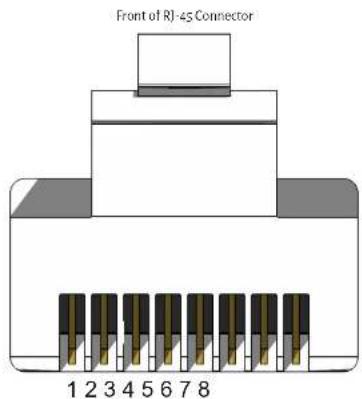
Gefen recommends the TIA/EIA-568-B wiring option. Use the table below when field-terminating cable for use with Gefen products.
| Pin Color Description | |
| 1 Orange / White TD+ (Transmit Data, positive differential signal) | |
| 2 Orange TD- (Transmit Data, negative differential signal) | |
| 3 Green / White RD+ (Receive Data, positive differential signal) | |
| 4 Blue Unused | |
| 5 Blue/White | Unused |
| 6 Green | RD- (Receive Data, negative differential signal) |
| 7 Brown / White | Unused |
| 8 Brown / White | Unused |
Rack Tray Installation
The following illustrations provide instructions for installing the Sender and/or Receiver unit(s) in the Gefen 1U Rock Tray (Gefen part no. EXT-RACK-1U-CRY).
Step 1 Step 2
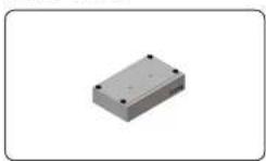
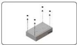
Step 3 Line up holes on unit and rack tray. Install coul, rail screws.
Step 4
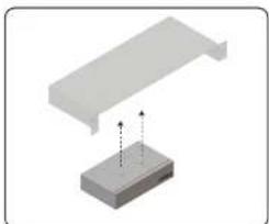
natural_image
3D diagram showing a mechanical component with a bracket and a base, no text or symbols present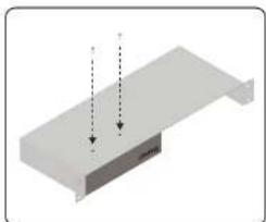
natural_image
3D diagram of a rectangular block with two vertical arrows pointing downward (no text or symbols)Step 5 Step 6
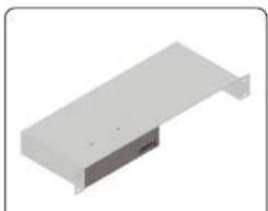
natural_image
3D rendering of a rectangular electronic component or enclosure with a flat top and central slot (no text or symbols visible)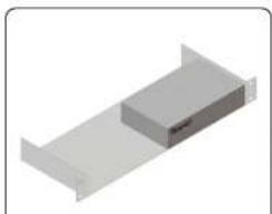
natural_image
3D rendering of a rectangular block with a small protrusion on top, placed on a flat base (no text or symbols)Specifications\*
Connectors & Indicators
| Video In Connector (Sender) | 1 x HDMI, DisplayPortTM, DVI, or VCA |
| Video Out Connector (Sender) | 1 x HDMI, DVI, or VGA (not avail on DisplayPortTM) |
| Video Out Connector (Receiver) | 1 x HDMI, DisplayPortTM, DVI, or VGA |
| Line In Connector (Sender) - 1 x 3.5mm mini-stereo, female | |
| Line Out Connector (Sender) - 1 x 3.5mm mini-stereo, female | |
| Mic In Connector (Receiver) - 1 x 3.5mm mini-stereo, female | |
| Headphones/Line Out Conn. (Receiver) | 1 x 3.5mm mini-stereo, female |
| Opt Out Connector (Receiver) | 1 x TOSLINK®(not available on VCA model) |
| USB Host Interface Port (Sender) - 1 x Type-B | |
| USB Device Ports (Receiver) - 2 x USB 2.0, Type-A- 2x USB 1.1, Type-A | |
| LAN Connector (Sender) - 1 x RJ-45, shielded, with PoE | |
| LAN Connectors (Receiver) - 2 x RJ-45, shielded, 1 with PoE | |
| RS-232 Connector (Sender) - 1 x DB-9, female | |
| RS-232 Connector (Receiver) - 1 x DB-9, male | |
| IR Sensor (Receiver) | (1) Located on front panel |
| IR Extender Type | EXT-RMT-EXTIRN |
| IR In/Ext Connector (Sender / Receiver) | 1 x 3.5mm mini-stereo, female |
| IR Out Connector (Sender / Receiver) | 1 x 3.5mm mini-stereo, female |
| Power Requirement (Sender / Receiver) | 5V DC, or PoE (802.3af standard) |
| Power Connector (Sender / Receiver) | 1 x 5V DC, locking, 5.5mm barrel/2.1mm pin |
| Power Indicator (Sender / Receiver) | 1 x LED, blue |
| Link Indicator (Sender / Receiver) | 1 x LED, green |
Continued on next page
Specifications
| Operational | |
| Operating Temperature: +32 to +122°F (0 to +50°C) | |
| Operating Humidity: 5% to 90% RH, non-condensing | |
| Storage Temperature: -4 to -185°F (-20 to +85°C) | |
| Storage Humidity: 0% to 95% RH, non-condensing | |
| MTBF: 50000 hours | |
| Physical | |
| Dimensions (W x H x D, not including connectors) | - Sender: 8.4" x 1.7" x 5.9" (214mm x 45mm x 150mm) - Receiver: 8.4" x 1.0" x 5.9" (214mm x 25mm x 150mm) |
* Features and specifications are subject to change without notice.
All trademarks and registered trademarks are properties of their respective owners.

GEFEN®
Nortek Security & Control, LLC
- Important Safety Instructions
- Warranty Information
- Contact Us
- Technical Support
- Web
- Mailing Address
- Operating Notes
- Important
- Supported USB Devices
- - Known supported devices
- - Known Limits:
- Licensing
- Features & Packing List
- Features
- Packing List - Sender Unit
- Packing List - Receiver Unit
- Table of Contents
- Introduction
- Installation
- Local Area Network (LAN) Connection
- Note
- Using a Direct Connection
- Supplementary Connections
- USB
- IR
- ▶ Audio
- RS-232
- LED Status
- Setting the Video Channel
- Setting the Channel using the Web Interface
- Setting the Channel using the Front Panel
- Blocking & Masking Video
- Mask Video
- Unicast & Multicast Modes
- Configuring Unicast Mode
- Switching between Sender units in Unicast mode
- Configuring Multicast Mode
- Success: New casting mode applied.
- Warning: Reboot for new settings to take effect.
- Discovery Mode
- Gefen Syner-G Discovery
- Finding Your Device
- RS-232 Control
- RS-232 under Unicast Mode
- RS-232 under Multicast Mode
- USB Control
- USB under Unicast Mode
- USB under Multicast Mode
- Active per request mode
- Active on link mode
- Audio Connections
- Audio Sources and De-Embedding
- Creating Video Walls
- Wall Size and Layout
- Bezel Compensation
- Setting the Video Mode
- Using the Web interface
- Changing the Password
- Utilities
- Reset using the Web Interface
- Reboot using the Web Interface
- Reboot using the Front Panel
- Telnet Access
- Commands
- #help
- Syntax
- help
- Parameters
- Example
- FACTORY_RESET
- FW UPGRADE
- GET CLK LOCK
- GET DEVICE DESC
- GET DISCOVERY
- GET EDID COPY
- GET_FIRMWARE_VERSION
- GET IP ADDRESS
- GET IP MODE
- GET MASK
- GET NET MODE
- GET_NETMASK
- GET PQ MODE
- #factory\_reset
- Related Commands
- rcboot
- #fw\_upgrade
- fw_upgrade firmware_file_v2.bin
- #get\_block
- get_block
- oct_mask
- set_block
- #get\_clk\_lock
- set clk lock
- #get\_device\_desc
- set device dose
- #get\_discovery
- get_discovery
- set showme
- #get\_discovery\_mode
- get_discovery_mode
- set showmo
- #get\_edid\_copy
- sct_odid_copy
- #get\_firmware\_version
- get firmware version
- fw_upgrade
- #get\_gateway
- get_gateway
- set notmask
- #get\_hdcp
- get_hdcp
- sct_hdcp_allow
- #get\_ip\_address
- get_ip_address
- set in mode
- set_web_port
- get_ip_mode
- set web port
- #get\_ipconfig
- get ipconfig
- get_mask
- set_mask
- #get\_net\_mode
- set not mode
- #get\_netmask
- qcel_qaleway
- qcel_ip_address
- qcel_lncnfiq
- qcel_web_port
- set_qaleway
- set_ip_address
- set_ip_node
- #get\_pq\_mode
- get_pg_mode
- get_pq_mode
- sct_pq_mode
- #get\_remote\_udp\_access
- get remote udp access
- sel._remote_udp_ip
- get_remote_udp_ip
- #get\_remote\_udp\_port
- get_remote_udp_port
- set_remote_udp_ip
- #get\_rx\_channel
- get tx channel
- set tx channel
- #get\_rx\_id
- get_rx_id
- set rx id
- #get\_serial\_allow
- get_serial_allow
- get serial baud
- gct serial parity
- get serial stop
- sct serial allow
- sct serial baud
- set serial bits
- sct serial parity
- set serial stop
- #get\_serial\_baud
- get_serial_baud
- get serial allow
- get serial bits
- set serial allow
- set serial baud
- set serial parity
- #get\_serial\_bits
- get_serial_bits
- gct serial baud
- get serial parity
- gct serial stop
- sct serial bits
- sct serial_stop
- #get\_serial\_parity
- #get\_serial\_stop
- #get\_showme
- get showme
- #get\_telnet\_access
- get_telnet_access
- get telnet login
- gct telnet port
- get telnet welcome
- sct telnet access
- sct tolnet pass
- set telnet login
- set telnet port
- sct tolnet welcome
- #get\_telnet\_login
- get_telnet_login
- sel_1elnet_1ogir
- #get\_telnet\_port
- get_telnet_port
- set_letnet_login
- #get\_telnet\_welcome
- get_telnet_welcome
- get telnet access
- set telnet access
- set telnet pass
- #get\_tx\_channel
- get_tx_channel
- get rx channel
- sct_tx_channel
- #get\_udp\_access
- get remote udp ip
- get udp port
- set remote udp access
- set remote uap port
- set udp port
- #get\_udp\_port
- get_udp_port
- get_usb_allow
- get_usb_mode
- get usb mode
- set usb mouse
- #get\_usb\_mouse
- get usb mouse
- #get\_video\_allow
- get_video_allow
- sct_video_allow
- #get\_vw
- get vw
- #get\_vw\_bc
- #get\_vw\_delay
- cet_vw_bc
- cet_vw_delay
- cet_vw_hscale
- cet_vw_layout
- cet_vw_csd
- cet_vw_pos
- cet_vw_shitt
- cet_vw_vscale
- set_vw
- set_vw_bc
- set_vw_delay
- set_vw_hscale
- set_vw_layout
- set_vw_csd
- set_vw_pos
- set_vw_shift
- set_vw_vscale
- #get\_vw\_hscale
- get_vw_bc
- #get\_vw\_layout
- get vw layout
- #get\_vw\_osd
- get vw osd
- #get\_vw\_pos
- get vw pos
- #get\_vw\_shift
- get_vw_shift
- #get\_vw\_vscale
- get vw vscale
- #get\_web\_port
- get_web_port
- get gateway
- set gateway
- set ip address
- set ip_mode
- set_notmask
- #reboot
- reboot
- #request\_usb
- request usb
- #set\_block
- set block 1
- #set\_clk\_lock
- set_block_param1
- set_clk_lock 100
- #set\_device\_desc
- set_description_param
- get_device_doso
- #set\_discovery
- set_discovery 0
- #set\_discovery\_mode
- set_discovery_mode 1
- #set\_edid\_copy
- get_edid_copy
- #set\_gateway
- set_gateway paraaml
- #set\_hdcp\_allow
- set_hdcp_allow param1
- get hdep allow
- #set\_ip\_address
- get notmask
- get web port
- set_ip_mode
- #set\_ip\_mode
- set_ip_mode_param1
- ct ip mode
- ect web port
- set to address
- #set\_mask
- set mask 1
- #set\_net\_mode
- set net mode 0
- get not mode
- #set\_netmask
- set_netmask_param1
- set_netmask 255.255.255.0
- set ip node
- set 15 mode
- #set\_pq\_mode
- set_pg_mode param1
- #set\_remote\_udp\_access
- cet_remote_udp_access
- set_remote_udp_access
- #set\_remote\_udp\_ip
- #set\_remote\_udp\_port
- set_remote_udp_port 50008
- #set\_rx\_id
- set_rx_id 1
- gct_rx_id
- #set\_serial\_allow
- set serial allow param1
- #set\_serial\_baud
- #set\_serial\_bits
- set serial bits param1
- cel serial band
- #set\_serial\_parity
- set_serial_parity_param1
- get_sorial_allow
- get_serial_parity
- set_serial_allow
- #set\_serial\_stop
- #set\_showme
- set_showme param1
- set_showme 1
- #set\_telnet\_access
- #set\_telnet\_login
- set_telnet_login_param1
- #set\_telnet\_pass
- set_telnet_pass param1
- set_telnet_pass b055man
- get_telnet_pass
- set_telnet_access
- set_telnet_login
- set_telnet_port
- set_telnet_welcome
- #set\_telnet\_port
- set_telnet_port_param1
- set_telnet_port 23
- get_tolnet_access
- get_tolnet_port
- set to|net login
- set_teinet_pass
- set_teinet_welcome
- #set\_telnet\_welcome
- set_telnet_welcome_param
- #set\_tx\_channel
- set_tx_channel 1
- #set\_udp\_access
- get_remote_udp_access
- get remote udp port
- #set\_udp\_port
- #set\_usb\_allow
- oct usb allow
- act usb mode
- #set\_usb\_mode
- set_udp_port param1
- set usb mode 0
- ct usb mode
- sct usb allow
- #set\_usb\_mouse
- #set\_video\_allow
- set video allow param1
- #set\_vw
- set vw 1
- #set\_vw\_bc
- set_vw_be param1 param2 param3 param4
- set vw bc 190 200 90 100
- #set\_vw\_delay
- set vw delay 16000
- #set\_vw\_hscale
- set vw hscale 1
- #set\_vw\_layout
- set vw layout 2 2
- #set\_vw\_osd
- set vw osd 1
- #set\_vw\_pos
- set_vw_pos 2 2
- #set\_vw\_shift
- get vw bc
- get vw delay
- get vw hscale
- get vw csd
- get vw shift
- #set\_vw\_vscale
- #set\_web\_port
- set_web_port 82
- #set\_webui\_ad\_pass
- set webu1 ad pass param1
- sct_wobui_user_pass
- #set\_webui\_user\_pass
- set webu user pass param1
- set_webui_user_pass mlniCn
- set webui ad pass
- r
- Network Cable Diagram
- Rack Tray Installation
- Specifications\*
- Specifications
Brand : Gefen
Model : EXT-UHDKA-LANS-RX
Category : Network switch