
UH330B M4 - Dishwasher Champion - Free user manual and instructions
Find the device manual for free UH330B M4 Champion in PDF.


| Brand | Champion |
| Model | UH330B M4 |
| Product Type | Undercounter Dishwasher |
| Series | M4 Series |
| Sanitization Method | High Temperature (Hot Water) |
| Built-in Booster Heater | Yes (40°F/22°C or 70°F/39°C rise) |
| Heat Recovery | Yes |
| Final Rinse | Fresh Water Final Rinse |
| Condensate Removal | Yes |
| Electrical Supply (Factory Wired) | Single Phase 208-240VAC, 60 Hz, 20A (3-wire + ground) |
| Electrical Supply (Convertible to) | Three Phase 208-240VAC, 60 Hz, 22/24A (4-wire + ground) |
| Control Voltage | 115VAC |
| Water Supply Connection | 1/2" NPT cold water, 6 ft. flexible hose with 3/4" female garden hose connector |
| Water Pressure (Flowing) | 25-95 psi |
| Drain Connection | 6 ft., 5/8" I.D. hose, 3/4" hose barb, max drain height 3 ft. [1 m], max flow 15 US gpm |
| Dimensions (Overall) | Width: 24" (610 mm) approx., Depth with door open: 42-3/8" [1076 mm], Height: adjustable to 34" [864 mm] countertop |
| Weight | Approx. 250 lbs (113 kg) |
| Cycle Time (Normal Wash) | Selectable: 70 sec (normal), 120 sec (medium), 195 sec (long); total cycle includes fill, wash, drain, rinse |
| Wash Temperature | Minimum 150°F (66°C) |
| Final Rinse Temperature | 180-195°F (82-91°C) |
| Chemical Dispensing Pumps | 2 built-in (Detergent and Rinse-aid), adjustable run time |
| Booster Fill Switch | Yes (first-time fill procedure required) |
| Safety Features | Door interlock (cycle stops if door open >5 sec), overtemp protection, lockout/tagout provision |
| Maintenance Interval | Every 2 hours of continuous operation (cleaning), daily/weekly/monthly schedules |
| Spare Parts Availability | Full parts list with part numbers provided in manual; service agents available |
Frequently Asked Questions - UH330B M4 Champion
User questions about UH330B M4 Champion
0 question about this device. Answer the ones you know or ask your own.
Ask a new question about this device
Download the instructions for your Dishwasher in PDF format for free! Find your manual UH330B M4 - Champion and take your electronic device back in hand. On this page are published all the documents necessary for the use of your device. UH330B M4 by Champion.
USER MANUAL UH330B M4 Champion
Installation/Operation Manual with Service Replacement Parts

UH330B
Undercounter Dishwashers M4 Series
UH330B M4
Condensate Removal
High Temperature
with built-in booster
Fresh Water Final Rinse
UL130 M4
Low Temperature
Chemical Sanitization
Wash Refresh Final Rinse
UH230 M4
High Temperature
without built-in booster
Fresh Water Final Rinse
UH230B M4
High Temperature
with built-in booster
Fresh Water Final Rinse
UH130 M4
High Temperature
without built-in booster
Wash Refresh Final Rinse
UH130B M4
High Temperature
with built-in booster
Wash Refresh Final Rinse

For future reference, record your dishwasher information in the box below.
Model Number Serial Number
Voltage____Hertz____Phase____
Service Agent ____ Tel: ____
Parts Distributor Tel:
National Service Department
In Canada: In the USA:
Toll-free: (800) 263-5798 Toll-free: (800) 858-4477
Tel: (905) 562-4195 Tel: (336) 661-1556
Fax: (905) 562-4618 Fax: (336) 661-1660
email: service@moyerdiebellimited.com email: service@championindustries.com
ATTENTION:
The model no., serial no., voltage, Hz and phase are needed to identify your machine and to answer questions.
The machine data plate is located on the lower front panel.
Please have this information ready if you call for service assistance.

REGISTER YOUR PRODUCT ONLINE
Make sure you are connected to the internet then enter an address below:
In the U.S.A.
http://www.championindustries.com/register
In Canada
http://www.championindustries.com/canada/register

The Dishwashing Machine Specialists
PRODUCT REGISTRATION BY FAX
COMPLETE THIS FORM AND FAX TO:
(336) 661-1660 in the USA
1-(800) 204-0109 in Canada
PRODUCT REGISTRATION CARD
Model
Serial #
Revision History
Revision History
A revision might be a part number change, a new instruction, or other information that was not available at print time. We reserve the right to make changes to these instructions without notice and without incurring any liability by making the changes. Equipment owners may request a revised manual, at no charge, by calling 1 (800) 858-4477 in the USA or by calling 1 (800) 263-5798 in Canada.
Revision Revised Serial Number Revision
Date Pages Effectivity Description
| 11.5.14 | All | W140946406 | Released First Edition |
| 12.3.14 | 95-149 | All | Revised UH330B Part Nos. |
| 3.2.15 FC, i | Corrected Effective Serial Number | ||
| 154 | All | Changed UH330B fuse to 6 Amp on the schematic | |
| 4.27.15 | 16118,119 | All | UH130, UH130b use 0706635 squeeze tube and pump |
| 4.27.15 | 154 | All | Updated UH330B ampacity charts |
| 5.13.15 | 129 | All | Changed 6A fuse P/N to 0513698 |
Limited Warranty
LIMITED WARRANTY
Champion Industries Inc. (herein referred to as Champion), 3765 Champion Blvd., Winston-Salem, North Carolina 27105, and P.O. Box 301, 2674 N. Service Road, Jordan Station, Canada, LOR 150, warrants machines, and parts, as set out below.
Warranty of Machines: Champion warrants all new machines of its manufacture bearing the name "Champion" and installed within the United States and Canada to be free from defects in material and workmanship for a period of one [1] year after the date of installation or fifteen [15] months after the date of shipment by Champion, whichever occurs first. [See below for special provisions relating to glasswashers.]
Warranty registration must be submitted to Champion within ten (10) days after installation either online on the Champion Industries website (http://www.championindustries.com/register) in the USA or http://www.championindustries.com/canada/register in Canada or by fax on the form provided at the front of this manual. If warranty registration is not returned to Champion within such period, the warranty will expire after one year from the date of shipment.
Champion will not assume any responsibility for extra costs for installation in any area where there are jurisdictional problems with local trades or unions. If a defect in workmanship or material is found to exist within the warranty period, Champion, at its election, will either repair or replace the defective machine or accept return of the machine for full credit; provided; however, as to glasswashers, Champion's obligation with respect to labor associated with any repairs shall end (a) 120 days after shipment, or (b) 90 days after installation, whichever occurs first. In the event that Champion elects to repair, the labor and work to be performed in connection with the warranty shall be done during regular working hours by a Champion authorized service technician. Defective parts become the property of Champion. Use of replacement parts not authorized by Champion will relieve Champion of all further liability in connection with its warranty. In no event will Champion's warranty obligation exceed Champion's charge for the machine. The following are not covered by Champion's warranty:
a. Lighting of gas pilots or burners.
b. Cleaning of gas lines.
c. Replacement of fuses or resetting of overload breakers.
d. Adjustment of thermostals.
e. Adjustment of clutches.
f. Opening or closing of utility supply valves or switching of electrical supply current.
g. Cleaning of valves, strainers, screens, nozzles, or spray pipes.
h. Performance of regular maintenance and cleaning as outlined in operator's guide.
i. Damages resulting from water conditions, accidents, alterations, improper use, abuse,
tampering, improper installation, or failure to follow maintenance and operation procedures.
j. Wear on Pulper cutter blocks, pulse vanes, and auger brush.
Examples of the defects not covered by warranty include, but are not limited to: (1) Damage to the exterior or interior finish as a result of the above, (2) Use with utility service other than that designated on the rating plate, (3) Improper connection to utility service, (4) Inadequate or excessive water pressure, (5) Corrosion from chemicals dispensed in excess of recommended concentrations, (6) Failure of electrical components due to connection of chemical dispensing equipment installed by others, (7)
Table of Contents
Table of Contents
Models UH130, UH130B, UH230, UH230B, UL130, UH330B
Revision History ....i
Limited Warranty ...... ii
Model Descriptions ...... v
Installation - Models UH130, UH130B, UH230, UH230B 1
Receiving - Models UH130, UH130B, UH230, UH230B, UL130.... 1
Placement - Models UH130, UH130B, UH230, UH230B, UL130 .... 1
Electrical Connections UH130, UH230 1 Phase w/o Booster 2
Electrical Connections UH130B, UH230B 1 and 3 PH Wiring Diagrams ...... 3
Connecting Incoming Power to the Main Terminal Block (1 and 3 PH)....4
Booster Heater Conversion from 1 to 3 PH 7
Water Connections - Models UH130, UH130B, UH230, UH230B.... 10
Drain Connection - Models UH130, UH130B, UH230, UH230B 11
Booster Fill Switch - (Filling the booster for the first time) UH130B, UH230B Only 14
Chemical Connections - Models UH130, UH130B, UH230, UH230B 16
Pumps and Injection Points - Detergent and Rinse-aid Dispensing Pumps 17
Pump Priming - Detergent and Rinse-aid Dispensing Pumps 19
Pump and Fill Adjustments - Detergent and Rinse-aid Dispensing Pumps.... 20
Operation - Models UH130, UH130B, UH230, UH230B 22
Loading Dish Racks - All Models.... 22
Normal Wash Mode - Models UH130 and UH130B Only 24
mal Wash Mode - Models UH230 and UH230B Only 25
Rinse Sentry Mode - UH130B and UH230B 26
Extended Wash Mode - Models UH230 and UH230B Only 26
Drain Mode - All Models 27
Cleaning - Models UH130, UH130B, UH230, UH230B 28
Table of Contents
Table of Contents (continued)
Models UL130, UH330B
Installation - UL130 35
Receiving 1
Placement....1
(Single Phase) Electrical Connections 36
Water Connection 37
Drain Connection 38
Pumps and Injection Points - Detergent, Rinse-aid and Sanitizer Dispensing Pumps......40
Pump Priming - Detergent, Rinse-aid and Sanitizer Dispensing Pumps....42
Pump and Tank Fill Adjustments....43
Operation - UL130 44
Loading Dish Racks 44
Normal Wash Mode 45
Extended Wash Mode 46
Drain Mode....47
Cleaning - UL130....48
Cleaning the Wash Tank 48
Cleaning the Wash Arms 48
De-liming....50
Maintenance - UL130 52
Maintenance - Daily, Weekly, Monthly 52
Troubleshooting-UH130, UH130B, UH230, UH230B, UL130 53
Table of Contents
Table of Contents (continued)
Model UH330B
Operation - Model UH330B 82
Loading Dish Racks 82
Control Panel and Wash Mode 84
Rinse Sentry Mode 85
Drain Mode 86
Cleaning - Model UH330B 87
Cleaning the Wash Tank 87
Cleaning the Rinse Arms 88
Cleaning the Wash Arms 88
Cleaning the Scrap Screen and Sump Strainer....89
De-liming 90
Maintenance - Model UH330B 91
Daily, Weekly, Monthly 91
Troubleshooting - UH330B 92
Service Replacement Parts 95
Electrical Schematics and Timing Charts 151
Model Descriptions
UH130B
Wash Refresh Pumped Final Rinse
High temperature hot water sanitizing dishwasher with built-in 40°F/22°C rise booster heater
or 70°F/39°C rise booster heater
Two built-in chemical dispensing pumps.
Field convertible from single phase to three phase operation.
208-240VAC/60/1 and 3 phase
UH230B
Fresh Water Final Rinse
High temperature hot water sanitizing dishwasher with built-in 40°F/22°C rise booster heater
or 70°F/39°C rise booster heater
Two built-in chemical dispensing pumps - Detergent, Rinse-aid
Field convertible from single phase to three phase operation.
208-240VAC/60/1 and 3 phase
UH130
Wash Refresh Final Rinse
High temperature hot water sanitizing dishwasher without built-in booster heater.
Two built-in chemical dispensing pumps - Detergent, Rinse-aid.
208-240VAC/60/1
UH230
Fresh Water Final Rinse
High temperature hot water sanitizing dishwasher without built-in booster heater.
Two built-in chemical dispensing pumps - Detergent, Rinse-aid.
208-240VAC/60/1
UL130
Chemical Sanitizing Wash Refresh Final Rinse
Low temperature chemical sanitizing dishwasher with three built-in chemical
dispensing pumps - Detergent, Rinse-aid, sanitizer.
120VAC/60/1
UH330R
Receiving and Placement - Installation
Receiving - UH130, UH130B, UH230, UH230B, UL130
NOTE:
The installation of your dishwasher must be performed by qualified service personnel familiar with food service equipment and must comply with all local health codes. Problems due to improper installation are not covered by the Limited Warranty.
NOTE:
The installation of the dishwasher must comply with all local electrical, plumbing, health and safety codes or in the absence of local codes, installed in accordance with the applicable requirements in the National Electrical Code, NFPA 70, Canadian Electrical Code (CEC), Part 1, CSA C22.1; and the Standard for Ventilation Control and Fire Protection of Commercial Cooking Operations, NFPA 96.
Placement - UH130, UH130B, UH230, UH230B, UL130
CAUTION:
Be careful when lifting and moving the dishwasher to prevent damage to the machine.
- Inspect the outside of the dishwasher carton for signs of damage.
- Remove the carton and inspect the dishwasher for damage.
- Check for any options or accessories that may have shipped with your dishwasher.
- Compare the installation site utility connections with the dishwasher utility connections and make sure they are the same.
-
The dishwasher can be installed as a free-standing unit or under a counter-top. The typical counter-top height in most locations is 34" [86cm].
-
It is highly recommended that the underside of the counter-top be clad in metal.
-
Under counter installations should
Counter-top

Installation - Model UH130, UH130B, UH230, UH230B
Electrical Connections - UH130, UH230 1PH without Built-in Booster

WARNING:
Electrocution or serious injury may result when working on an energized circuit.
Disconnect power at the main breaker or service disconnect switch before working on the circuit.
Lock-out and tag the breaker or service disconnect switch to indicate that work is being performed on the circuit.
Refer to the connection diagram below for single a phase machine without a built-in booster.
- A three prong 4 foot power cord and plug is prewired with the machine for connection to a 115VAC power source.
SINGLE PHASE POWER CONNECTION
Models UH130 and UH230

Model UH130, UH130B, UH230, UH230B - Installation
Electrical Connections - UH130B, UH230B with Built-in Booster
1PH and 3PH Wiring Diagrams
! ATTENTION !
ALL DISHWASHERS ARE SHIPPED FROM THE FACTORY WIRED FOR SINGLE PHASE OPERATION UNLESS SPECIFIED AT THE TIME OF ORDER.
IF YOU ARE CONVERTING A SINGLE PHASE MACHINE TO THREE PHASE BE SURE TO FOLLOW THE BOOSTER WIRING INSTRUCTIONS ON PAGES 7-8.
Refer to the connection diagrams below to connect main incoming power to the dishwasher.
THREE PHASE POWER CONNECTION
Models UH130B and UH230B

! VERY IMPORTANT !
THE ELECTRICAL POWER MUST BE A 4-WIRE PLUS GROUND SUPPLY WHICH
SINGLE PHASE POWER CONNECTION
Models UH130B and UH230B

! VERY IMPORTANT !
THE ELECTRICAL POWER MUST BE A 3-WIRE PLUS GROUND SUPPLY WHICH INCLUDES A CURRENT CARRYING NEUTRAL.
Installation - Model UH130, UH130B, UH230, UH230B
Connecting Incoming Power to the Main Terminal Block for 1PH and 3PH Machines with Boosters-UH130B, UH230B

WARNING:
Electrocution or serious injury may result when working on an energized circuit.
Disconnect power at the main breaker or service disconnect switch before working on the circuit.
Lock-out and tag the breaker or service disconnect switch to indicate that work is being performed on the circuit.
! VERY IMPORTANT! PROVIDE A 3 FEET/1 METER SERVICE LOOP IN THE POWER SUPPLY CABLE TO SERVICE THE DISHWASHER.
! SINGLE PHASE POWER REQUIREMENT !
SINGLE PHASE UH130B and UH230B
The electrical power must be a 3-wire plus ground supply which includes a current carrying neutral.
Model UH130, UH130B, UH230, UH230B - Installation
Connecting Incoming Power to the Main Terminal Block for 1PH and 3PH Machines with Boosters-UH130B, UH230B
Refer to the photo below:
- Remove the lower front dishwasher panel.
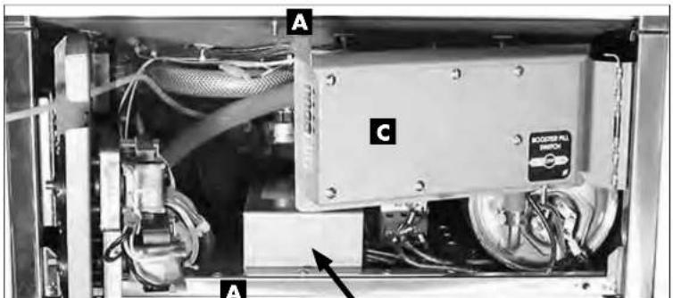
- Remove the retaining fasteners (A) from the swing-out brackets and swing the chemical pump bracket (B) and the chemical circuit board bracket (C) out of the way as shown.
(continued on next page)
Installation - Model UH130, UH130B, UH230, UH230B
Connecting Incoming Power to the Main Terminal Block for 1PH and 3PH Machines with Boosters
(continued from previous page)
Refer to the photo below:
- Provide a 3 foot/1 meter service loop in the power supply cable to service the machine
- Route the power cable from the rear of the machine to the terminal block making sure the cable does not touch the booster tank.
- Connect the power cable to the terminal block bracket using a suitable strain relief connector.
- Connect the power wires according to the wiring diagrams on page 3 for either single phase or three phase operation.
- Swing the chemical pump bracket and the chemical board back into position and secure with the existing fasteners.

Model UH130, UH130B, UH230, UH230B - Installation
Booster Heater Conversion from 1PH to 3 PH Operation
! VERY IMPORTANT! THE BOOSTER HEATER IS WIRED FOR 1PH OPERATION WHEN SHIPPED. FOLLOW THE INSTRUCTIONS BELOW TO WIRE THE BOOSTER FOR 3PH.

WARNING:
Electrocution or serious injury may result when working on an energized circuit.
Disconnect power at the main breaker or service disconnect switch before working on the circuit.
Lock-out and tag the breaker or service disconnect switch to indicate that work is being performed on the circuit.
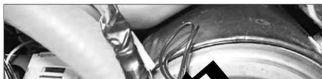
- To convert the booster heater from single phase to three phase operation, locate the booster wire labeled 1H3 that is cable-tied to the booster hose.
- Remove the shrink insulation from the terminal and connect to the booster heater element as shown in the wiring diagram on page 8.
Installation - Model UH130, UH130B, UH230, UH230B
Booster Heater Conversion from 1PH to 3 PH Operation (continued)
! VERY IMPORTANT !
THE BOOSTER HEATER IS WIRED FOR 1PH OPERATION WHEN SHIPPED. FOLLOW THE INSTRUCTIONS BELOW TO WIRE THE BOOSTER FOR 3PH.
- Disconnect the existing booster heater wires and change the booster heater element jumpers as shown in the illustration below
- Connect wires 1H1, 1H2, and 1H3 as shown below.
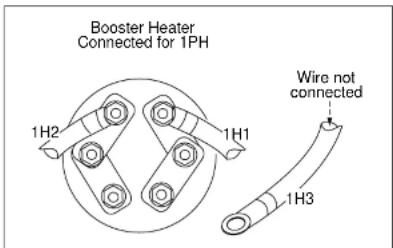

Wiring Diagram - Booster heater element connections shown for 1 phase and 3 phase operation.
- A replacement 3PH data plate is stowed on the back of the lower front access panel.
- Replace the existing 1PH data plate on the front of the panel with the new 3PH data plate. Discard the 1PH data plate
Model UH130, UH130B, UH230, UH230B - Installation
Completing the 1PH to 3PH Electrical Conversion
! ATTENTION! CHANGE THE DATA PLATE ON THE LOWER FRONT PANEL OF THE MACHINE AFTER THE MACHINE IS WIRED FOR 3PH AND THE BOOSTER HEATER IS CONNECTED FOR 3PH.
- The data plate on the dishwasher lower front panel must be changed after the machine is converted from single phase operation to three phase operation.
- Locate the replacement data plate stowed on the back of the lower front panel.
- Remove the paper backing from the label and carefully place it over the existing data plate label making sure it covers the label completely.
4 Re-install the lower front panel to complete the conversion.

Installation - Model UH130, UH130B, UH230, UH230B
Water Connections - UH130, UH130B, UH230, UH230B
! VERY IMPORTANT !
Make sure the flexible water supply and drain hoses are not kinked.
Plumbing connections must allow the machine to be pulled out for service and cleaning.
Plumbing connections must comply with national, provincial local plumbing and sanitary codes. Only qualified service personnel familiar with food service equipment should install the machine.
The installing plumber must thoroughly flush the water supply line to remove all debris BEFORE connecting the water supply line to the machine.
- All models have a 6 ft. flexible hot water fill hose with a 3/4" female garden hose connector.
- A 1/2" or larger main incoming supply line must be installed to the dishwasher.
- A 1/2" or larger shut-off valve should be installed in the main water supply, as close to the dishwasher as possible for servicing.
FOR UH130: The UH130 has a built-in flow control. The flowing incoming hot water supply pressure must be between 25-95 psi. The hot water supply must provide a minimum of 180° F/ 82° C, measured at the dishwasher.
FOR UH130B: The UH130B has a built-in flow control. The flowing incoming hot water supply pressure must be between 25-95 psi. The hot water supply must provide a minimum of 140°F/60°C, measured at the dishwasher for 40°F/22°C rise booster or 110°F/43°C for 70°F/80°C.
Model UH130, UH130B, UH230, UH230B - Installation
Drain Connections - UH130, UH130B, UH230, UH230B
! VERY IMPORTANT !
Do not connect the drain hose to a disposer. The dishwasher will not drain correctly.
Refer to the photo below.
- All models are equipped with a 6 ft.. 5/8" I.D. drain hose. The maximum drain height connection must not exceed 3 ft.[1 m] and must be vented to prevent the wash tank from siphoning.
- The drain hose is located at the rear of the dishwasher, and is secured to the rear of the machine by two clamps to maintain an anti-siphoning loop in the drain hose.
- A 3/4" hose barb fitting is strapped to the drain hose prior to shipment. The service part number for the hose barb is P/N 0512321.
- Additional plumbing parts must be supplied by the plumbing installer.
- The maximum drain flow is 15 US gpm/12.4 imp gpm/60 lpm.
! ATTENTION !
FAILURE TO FOLLOW THE DRAIN CONNECTION INSTRUCTIONS MAY VOID THE WARRANTY.
Installation - Model UH130, UH130B, UH230, UH230B
Drain Connection - UH130, UH130B, UH230, UH230B (continued)
NOTE
Plumbing connections must comply with national, provincial local plumbing and sanitary codes.
DO NOT REMOVE THE CLAMPS HOLDING THE DRAIN HOSE TO THE BACK OF THE DISHWASHER.
DO NOT CONNECT THE DRAIN HOSE TO A DISPOSER.
DO NOT REDUCE THE SIZE OF THE DRAIN HOSE CONNECTION NOR USE A DOMESTIC DRAIN FITTING.
DO NOT ADD ADDITIONAL LENGTH TO THE DRAIN HOSE.
DO NOT ALLOW THE DRAIN HOSE TO KINK.
For a Direct Drain Connection:
- Install the drain hose to an 1-1/2" or larger vented "WYE" drain fitting.
- CONNECTION TO A "TEE" FITTING WILL PREVENT THE DISHWASHER FROM DRAINING COMPLETELY.
Drain Hose
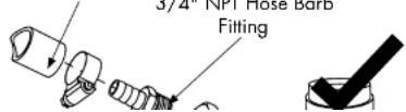

Model UH130, UH130B, UH230, UH230B - Installation
Drain Connection
UH130, UH130B, UH230, UH230B
For an Indirect Drain Connection:
- A 1" [25.4mm] minimum air gap must be provided between the outlet of the dishwasher drain hose and the flood-level rim of the floor drain, floor sink or any other locally approved drain receptacle. (See illustration below.)
![Dishwasher Drain Hose Minimum Air Gap [25.4mm] Floor Floor Drain](/content/2026/05/925777/images/fb4b96f31bd971ada621a6443bee5acbae333c04f486c74d106c7c96c52f70c5.jpg)
! VERY IMPORTANT !
Installation - Model UH130B, UH230B
Booster Fill Switch - (Filling the booster tank for the first time) UH130B and UH230B only
! CAUTION! AVOID PERMANENT DAMAGE TO THE BOOSTER HEATER DO NOT TURN THE DISHWASHER POWER SWITCH ON WHEN FILLING THE BOOSTER FOR THE FIRST TIME.
THE BUILT-IN BOOSTER TANK WAS DRAINED BEFORE SHIPMENT AND MUST BE REFILLED BEFORE OPERATING THE DISHWASHER.
To refill the booster for the first time:
- Turn the main breaker or disconnect switch to the dishwasher ON.
- DO NOT PUSH THE DISHWASHER ON-OFF/DRAIN POWER SWITCH TO THE ON POSITION.
- Locate the booster fill switch and note the switch is in the OFF position.
(continued on next page)
Model UH130B, UH230B - Installation
Booster Fill Switch - (Filling the booster tank for the first time)
UH130B and UH230B only
- PUSH AND HOLD the booster fill switch in the FILL position until water starts filling inside the wash compartment.
- Release the FILL switch.

- PUSH the booster fill switch to the ON position and release.
- The booster fill operation is complete.
- Replace the lower front panel on the machine.
Installation - Model UH130, UH130B, UH230, UH230B
Chemical Connections
UH130, UH130B, UH230, UH230B
! VERY IMPORTANT !
ALWAYS USE A COMMERCIAL-GRADE NON-CHLORINATED DETERGENT. PLACE THE CHEMICAL SUPPLY CONTAINERS AS CLOSE TO THE MACHINE AS POSSIBLE. DO NOT ELEVATE THE CHEMICAL CONTAINERS ABOVE THE FINISHED FLOOR.
! VERY IMPORTANT!
Contact a chemical supplier for detergent and rinse-aid chemicals. The chemical supplier must adjust the chemical dispensing pumps for water hardness and food soil types.
Chemical Dispensing Pumps
- The detergent and rinse-aid pumps are located on the lower left-side of the machine behind the lower-front access panel.
- Each pump is equipped with 6 feet [1.8 m] of pick-up tubes consisting of supply tubing, stiffener tubes, and strainers.
- The pick-up tubes are stowed on the back of the machine for shipping.
- A red label marked DETERGENT and a blue label marked RINSE-AID identify the chemical lines.

Model UH130, UH130B, UH230, UH230B - Installation
Pumps and Injection Points - Detergent and Rinse-aid Dispensing Pumps
UH130, UH130B
! VERY IMPORTANT !
ALWAYS USE A COMMERCIAL-GRADE NON-CHLORINATED DETERGENT. PLACE THE CHEMICAL SUPPLY CONTAINERS AS CLOSE TO THE MACHINE AS POSSIBLE. DO NOT ELEVATE THE CHEMICAL CONTAINERS ABOVE THE FINISHED FLOOR.
Injection Point Locations
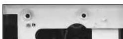
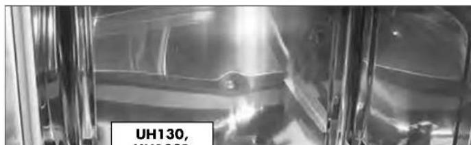
- For UH130 and UH130B, the detergent and rinse-aid enter the wash tank compartment through a fitting on back right corner of the wash compartment.
(continued on next page)
Installation - Model UH130, UH130B, UH230, UH230B
Pumps and Injection Points - Detergent and Rinse-aid Dispensing Pumps UH230, UH230B
- For UH230 and UH230B, the detergent enters the wash tank compartment through a fitting on the back right corner of the wash compartment. Rinse-aid enters the final rinse piping through a fitting near the vacuum breaker.
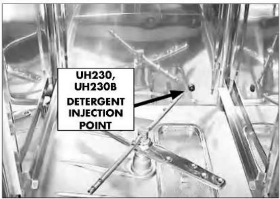

Model UH130, UH130B, UH230, UH230B - Installation
Pumps and Injection Points - Detergent and Rinse-aid Dispensing Pumps
UH130, UH130B and UH230, UH230B
Priming the Dispensing Pumps
! VERY IMPORTANT !
The chemical dispensing pumps must be primed before operating the dishwasher and whenever the chemical container is changed.

UH130, UH130B Control Panel

UH230, UH230B Control Panel
- The chemical dispensing pump supply lines must be primed before they will pump the chemicals properly.
- Make sure the chemical containers are full and the correct with one tube are in their containers.

Installation - Model UH130, UH130B, UH230, UH230B
Detergent and Rinse-aid Dispensing Pumps - Pump and Fill Adjustments UH130, UH130B and UH230, UH230B
! ATTENTION !
The amount of dispensed chemical is determined by the run time of the dispensing pump.
Refer to the photo below:
- The chemical dispensing pump run and the tank fill adjustment screws are located on the end of the chemical circuit board swing-out bracket.
- It is not necessary to swing the bracket out to make adjustments, but if desired, remove the mounting nut (A) and swing the bracket (B) out and to the right.
- Refer to the next page for adjustment instructions.
! VERY IMPORTANT !
INSPECT & REPLACE THE CHEMICAL DISPENSING PUMP SQUEEZE TUBES EVERY SIX MONTHS.

Model UH130, UH130B, UH230, UH230B - Installation
Detergent and Rinse-aid Dispensing Pumps - Pump and Fill Adjustments UH130, UH130B and UH230, UH230B
Refer to the photo below:
To adjust the amount of chemicals dispensed by the pumps:
- Make sure the chemical containers are full and the pick-up tubes are in their proper containers.
- Turn the dishwasher power switch ON. The switch will illuminate and the dishwasher will fill with water.
- Run a normal dishwasher cycle and test detergent and rinse-aid concentrations according to the chemical supplier's instructions.
CAUTION:
Excessive pressure to the potentiometers when adjusting can result in bent or broken adjusting screws.
5. Each dispensing pump has a clearly marked adjustment screw. Turn the screw CW to increase the run time of the dispensing pump and CCW to reduce the run time.
UH130 UH130B only

Operation - Model UH130, UH130B and UH230, UH230B
Operation - UH130, UH130B and UH230, UH230B
Loading Dish Racks
! VERY IMPORTANT! DO NOT OVERLOAD THE DISH RACK. LOAD ONE DISH RACK INTO THE MACHINE AT A TIME.
- Prescrap and rinse the wares before loading to remove large food particles.
- Load soiled wares into the dish rack. Place plates and glasses in a peg rack. Place cups and bowls in a flat bottom rack. Place utensils in a single layer in a flat-bottom rack. Place pots and pans in a flat-bottom rack.
Do not overload the dish rack. Wash one dish rack at a time.
- Slide one dish rack into the wash compartment making sure that wares do not interfere with the rotating spray arms. Do not wash more than one dish rack at a time.
Prescrap and rinse wares before loading into the machine.

Model UH130, UH130B and UH230, UH230B - Operation
Loading Dish Racks (continued)

Load pots and pans in a flat-bottom rack.
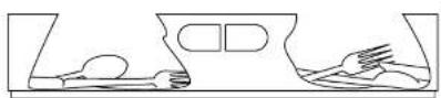
Load utensils in a single layer in a flat-bottom rack.

Load cups and bowls in a flat-bottom rack.
Operation - Model UH130, UH130B
Operation - UH130, UH130B Only
Normal Wash Mode

- Close the dishwasher front door.
- Push the dishwasher Power Switch UP to turn the power ON.
- The power switch will illuminate and the machine will fill with water.
- Wait until the wash temperature gauge indicates a minimum of 150°F/66°C.
PLACE AN EMPTY DISHRACK IN THE MACHINE AND RUN THE FIRST CYCLE EMPTY TO HEAT THE WASH TANK INTERIOR.
- Load the dish rack into the machine. Wash one dish rack at a time.
- Close the door, then press the START BUTTON for 1 second. The green in-cycle light will illuminate and the wash cycle will begin. The total cycle is approximately 141 seconds.
- Opening the door during a cycle will stop the dishwasher. If the door is open more than 5 seconds the cycle will restart from the beginning, if open less than 5 seconds the cycle will resume where it left off when the dishwasher door is closed.
- The final rinse cycle begins at the end of the wash cycle. The machine drains and then refills with fresh water hot water. Check the rinse temperature gauge during the final rinse. It must indicate a minimum of 180-195°F/82-91°C. The final rinse water is retained for the next wash cycle.
Model UH230 and UH230B Only - Operation
UH230 and UH230B Only - Operation
Normal Wash Mode
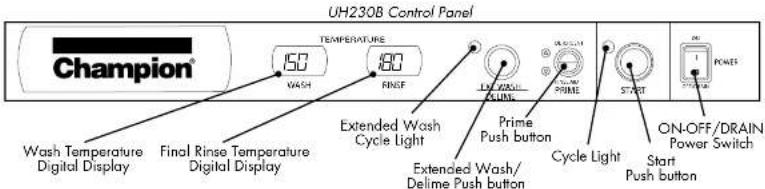
- Close the door.
- Push the dishwasher Power Switch UP to turn the power ON.
- The power switch will illuminate and the machine will fill with water.
- Check the pressure gauge as the machine fills and make sure the incoming water pressure is between 20-22 PSI.
Wait until the wash temperature gauge indicates a minimum of 150°F/66°C.
PLACE AN EMPTY DISHRACK IN THE MACHINE AND RUN THE FIRST CYCLE EMPTY TO HEAT THE WASH TANK INTERIOR.
- Load the dish rack into the machine. Wash one dish rack at a time.
- Close the door, then press the START BUTTON for 1 second. The green in-cycle light will illuminate and the wash cycle will begin. The total cycle is approximately 90 seconds.
- Opening the door during a cycle will stop the dishwasher. If the door is open more than 5 seconds the cycle will restart from the beginning, if open less than 5 seconds the cycle will resume where it left off when the dishwasher door is closed.
- The final rinse cycle begins at the end of the wash cycle. The machine drains and retains a portion of the final rinse water for the next wash cycle.
Operation - Model UH130, UH130B and UH230, UH230B
UH130B and UH230B Rinse Sentry Mode
! ATTENTION !
DOOR LEFT OPEN DURING WASH CYCLE
If the dishwasher door is left open for more than 5 seconds during the normal wash mode, then the dishwasher cycle will reset to the beginning of the normal wash cycle.
! ATTENTION !
RINSE SENTRY MODE WILL EXTEND WASH CYCLE TIME
In the event that the final rinse temperature has not reached 180-195°F/82-91°C after the wash cycle, the rinse sentry will extend the wash cycle time until the booster reaches 180-195°F/82-91°C. If the proper temperature is not reached within 5 minutes, the machine will leave the rinse sentry mode and complete the cycle.
Extended Wash Mode
Model UH230, UH230B Only
The Extended Wash Mode is used to wash heavily soiled items such as pots, pans and other wares that require more washing time than the standard 90 second Normal Wash Mode. The dishwasher will remain in the Extended Wash Mode until the operator exits the mode or a maximum of 15 minutes, whichever occurs first.
- Load a dish rack into the dishwasher, close the door and press the START button.
- The green in-cycle light will illuminate and the dishwasher will begin a normal wash cycle.
- Wait 10 seconds for the detergent to enter the wash compartment before pressing the EXT WASH button.

Press the EVT WASH button to place the
Models UH130, UH130B, UH230, UH230B - Operation
UH130, UH130B and UH230, UH230B
Drain Mode
The dishwasher will enter the drain mode whenever the Power Switch is pushed down to the OFF/DRAIN position.
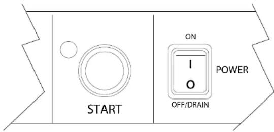
- Push the illuminated power switch down to the OFF/DRAIN position. The power switch light will go out.
- The cycle light will illuminate and the machine will drain.
- The machine, will flush, perform 3 short drain cycles and then drain completely.
- The cycle light will go out indicating that the drain cycle is complete. Do not open the door until the light goes out.
! VERY IMPORTANT !
Draining Problems Related To Improper Installation.
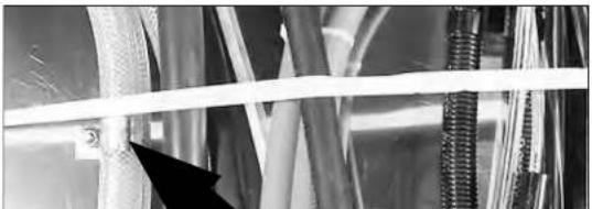
Problems with draining are often the result of improper installation. The drain hose is looped and clamped as shown in the photo below and must not be changed.
Cleaning - Model UH130, UH130B, UH230, UH230B
Cleaning - UH130, UH130B and UH230, UH230B
! VERY IMPORTANT !
DRAIN AND CLEAN THE DISHWASHER EVERY 2 HOURS OF CONTINUOUS OPERATION, AFTER EACH MEAL PERIOD, AND AT THE END OF THE DAY.
All Models
Cleaning the wash tank:
- Remove the upper and lower spray arms and flush clean in a sink.
- Remove the scrap screen taking care that debris does not fall off the screen and into the wash tank or sump. Flush the screen clean in a sink. Be sure to back-flush the screen.
- DO NOT strike the scrap screen on solid surfaces.
- Check the sump for foreign material.
- Clean the pump intake strainer in the bottom of the sump.
- DO NOT scrub the interior with metal scrub pads.
- Check the sump heating element for lime deposits and gently remove with a scouring pad. DO NOT USE METALLIC SCRUB PADS.
- Wipe the exterior of the dishwasher with a soft clean cloth and a mild detergent.
- Leave the door open to aid in overnight drying.
! ATTENTION !
DO NOT USE METALLIC SCRUB PADS TO CLEAN THE MACHINE. DO NOT SPRAY THE EXTERIOR OF THE MACHINE WITH WATER.
Model UH130, UH130B, UH230, UH230B - Cleaning
UH130, UH130B and UH230, UH230B - Cleaning
UH130, UH130B
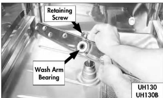
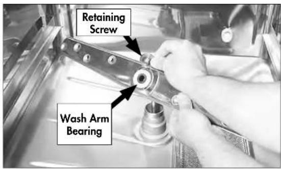
- Unscrew the retaining screw from the upper and lower interchangeable spray arms.
- Flush the spray arms clean in a sink. Be sure to flush the wash arm bearings.
UH230, UH230B
- Unscrew the retaining screw from the upper and lower rinse arms. The rinse arms are interchangeable.
- Remove the upper and lower wash arms and flush clean in a sink.
- Flush the wash arm bearings clean.
Cleaning - Model UH130, UH130B, UH230, UH230B
Cleaning - UH230, UH230B Only

UH230, UH230B Rinse Arms
-
There are two rinse arms in the UH230, and UH230B. They are interchangeable.
-
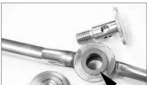
Remove the spindle assembly and end plugs in each pipe and flush the rinse pipes.
-
Inspect the rinse arm bearings for wear and replace as necessary.
-
Clean the rinse arm nozzles with a small paper clip.
-
Reassemble the rinse arm assemblies.
Model UH130, UH130B, UH230, UH230B - Cleaning
All Models - Cleaning
All Models
Scrap Screen and Sump Strainer
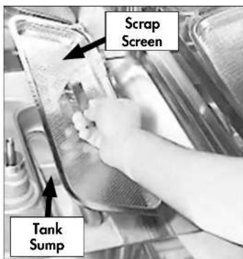
- Lift the scrap screen straight up and out of the machine to prevent food particles from falling into the tank sump.
- Flush the scrap screen in a remote sink making sure to back-flush both side of the screen.
- Wipe the tank sump of water and debris.
- Carefully inspect the pump intake strainer. This strainer is not removable but must be thoroughly cleaned before reinstalling the scrap screen.
! ATTENTION !
A CLOGGED OR RESTRICTED SUMP STRAINER WILL PREVENT THE PROPER WASHING, RINSING AND DRAINING OF THE
De-liming - Model UH130, UH130B, UH230, UH230B
De-liming Cautions and Warnings
A de-liming agent must be used in accordance with your chemical supplier's instructions.
DANGER:
Death or serious injury may result when de-liming solution is mixed with sodium hypochlorite sanitizing agent. Mixing may cause hazardous gases to form. De-liming solution and other acids must never be mixed with chlorine, iodine, bromine, or fluorine.
CAUTION:
Skin contact with de-liming solutions can cause severe irritation and possible chemical burns. Always wear eye protection, rubber gloves and protective clothing when handling chemicals.
UH130 and UH130B De-liming Procedure
Follow the procedures below to de-lime the UH130, UH130B dishwasher.
- Open the dishwasher door and remove any dish rack.
- Turn the power switch on the dishwasher to the ON position.
- Remove the detergent and rinse-aid chemical supply tubing from their chemical supply containers.
- Place the detergent and rinse-aid tubing in a container of hot water.
- Press and hold the prime switch UP in the DETERGENT position to flush all of the detergent from the supply tubing. Release the switch.
- Press and hold the prime switch DOWN in the RINSE AID position to flush all of the rinse-aid from the supply tubing. Release the switch.
Read and Follow the De-liming Cautions and Warnings on page 32 before de-liming the machine..
UH230 and UH230B De-liming Procedure
Follow the procedures below to de-lime the UH230, UH230B dishwasher.
- Open the dishwasher door and remove any dish racks.
- Turn the power switch on the dishwasher to the ON position.
- Remove the detergent and rinse-aid chemical supply tubing from their chemical supply containers.
- Place the tubing in a container of hot water.
- Press and hold the prime switch UP in the DETERGENT position to flush the detergent from the supply tubing. Release the switch.
- Press and hold the prime switch DOWN in the RINSE AID position to flush the rinse-aid from the supply tubing. Release the switch.
- Turn the dishwasher power switch to OFF/DRAIN to drain the wash tank. The green cycle light will go out in about 2 minutes.
- Always wear eye protection, rubber gloves and protective clothing when handling chemicals. Open the door and carefully add the de-liming chemical to the wash tank in accordance with your chemical supplier's instructions. Be careful to avoid splashing
Maintenance - Model UH130, UH130B, UH230, UH230B
UH130, UH130B and UH230, UH230B - Maintenance
Follow the maintenance schedules below to keep the dishwasher operating most efficiently.
Daily Maintenance
- Make sure the water supply is on and that the drain is not clogged.
- Check the temperature gauges and/or displays to ensure they are operating.
- Make sure the dish racks are in good condition.
- Check the chemical containers and refill as required.
- Follow the cleaning procedures provided in the Cleaning Section.
Weekly Maintenance
- Perform Steps 1-5 in the Daily Maintenance.
- Inspect water lines for leaks.
- Check for water leaks underneath the dishwasher.
- Make sure the flexible water fill and drain hoses are not kinked.
- Make sure that the dishwasher is level.
- Clean accumulated lime deposits from the wash tank heating element.
- Inspect the scrap screen and replace it if damaged.
- Check the spray arms and replace or repair if damaged.
Monthly Maintenance
- Perform the Daily and Weekly Maintenance listed above.
- Clean the chemical dispenser pick-up tubing for the chemical dispensing pumps.
Model UL130 Low Temperature Chemical Sanitizing Dishwasher
Model UL130 Low Temperature Chemical Sanitizing Undercounter Dishwasher
Installation - Model UL130
(Single Phase) Electrical Connections - UL130

WARNING:
Electrocution or serious injury may result when working on an energized circuit.
Disconnect power at the main breaker or service disconnect switch before working on the circuit.
Lock-out and tag the breaker or service disconnect switch to indicate that work is being performed on the circuit.
! ATTENTION !
A qualified electrician must connect the main incoming power to the dishwasher in accordance with all local codes and regulations or in the absence of local codes in accordance with the National Electrical Code or the Canadian Electrical Code.
Refer to the connection diagram below for single a phase machine without a built-in booster.
- A three prong 4 foot power cord and plug is prewired with the machine for connection to a 115VAC power source.

! VERY IMPORTANT !
Make sure that the flexible water supply and drain hoses are not kinked.
Plumbing connections must allow the machine to be pulled out for service and cleaning.
Plumbing connections must comply with national, provincial local plumbing and sanitary codes. Only qualified service personnel familiar with food service equipment should install the machine.
The installing plumber must thoroughly flush the water supply line to remove all debris BEFORE connecting the water supply line to the machine.
- All models have a 6 ft. flexible hot water fill hose with a 3/4" female garden hose connector.
- A 1/2" or larger main incoming supply line should be installed to the dishwasher.
- We recommend that a 1/2" or larger shut-off valve be installed in the main water supply, as close to the dishwasher as possible for servicing.
- The UL130 has a built-in flow control which requires that the incoming hot water supply pressure must be between 25-95 psi.
- The hot water supply must provide a minimum of 120° F/ 49° C, measured at the dishwasher; however, 140° F/ 60° C is recommended.
- A water hardness of 3 grains/gal (US) [51.3 mg/L] or less is recommended. Hard water can adversely affect wash results.
Drain Connection - UL130
- All models have a 6 ft.. 5/8" I.D. drain hose. The maximum drain height connection must not exceed 3 ft.[0.9 m].
- A 3/4" hose barb fitting is strapped to the drain hose to connect the drain hose to a wye drain fitting. The service part number for the hose barb is P/N 0512321.
- The maximum drain flow is 15 US gpm/12.4 imp gpm/60 lpm.
Installation - Model UL130
Drain Connection - UL130 (continued)
NOTE
Plumbing connections must comply with national, provincial local plumbing and sanitary codes.
DO NOT REMOVE THE CLAMPS HOLDING THE DRAIN HOSE TO THE BACK OF THE DISHWASHER.
DO NOT CONNECT THE DRAIN HOSE TO A DISPOSER.
DO NOT REDUCE THE SIZE OF THE DRAIN HOSE CONNECTION NOR USE A DOMESTIC DRAIN FITTING.
DO NOT ADD ADDITIONAL LENGTH TO THE DRAIN HOSE.
DO NOT ALLOW THE DRAIN HOSE TO KINK.
For a Direct Drain Connection:
- Install the drain hose to an 1-1/2" or larger "WYE" vented drain fitting.
- CONNECTION TO A "TEE" FITTING WILL PREVENT THE DISHWASHER FROM DRAINING COMPLETELY.
Drain Hose


For an Indirect Drain Connection:
- A 1" [25.4mm] minimum air gap must be provided between the outlet of the dishwasher drain hose outlet and the flood-level rim of the floor drain, floor sink or any other locally approved drain receptacle. (See illustration below.)
![Dishwasher Drain Hose 1" Floor Minimum Air Gap [25.4mm] Floor Drain](/content/2026/05/925777/images/40cff90d1c183bd3ca147ef03404122015316024cda9576a4067862312c3dd6c.jpg)
! VERY IMPORTANT! IMPROPER INSTALLATION OF MACHINE DRAIN HOSE.
Machine drain problems are often the result of improper installation and may not be covered by the limited warranty.
Installation - Model UL130
Pumps and Injection Points - Detergent, Rinse-aid and Sanitizer
Dispensing Pumps - UL130
! VERY IMPORTANT !
ALWAYS USE A COMMERCIAL-GRADE NON-CHLORINATED DETERGENT. PLACE THE CHEMICAL SUPPLY CONTAINERS AS CLOSE TO THE MACHINE AS POSSIBLE.
DO NOT ELEVATE THE CHEMICAL CONTAINERS ABOVE THE FINISHED FLOOR.
! VERY IMPORTANT!
Contact a chemical supplier for detergent and rinse-aid chemicals. The chemical supplier must adjust the chemical dispensing pumps for water hardness and food soil types.
- The chemical dispensing pumps are located on a center bracket behind the lower-front access panel.
- Each pump is equipped with 6 feet [1.8 m] of supply tubing, stiffener tubes, and strainers.
- A RED label marked DETERGENT, a BLUE label marked RINSE-AID and a WHITE Label marked SANITIZER identify the chemical lines.
- The chemicals enter the wash tank compartment through a fitting located on the rear right-hand side of the wash compartment.


Model UL130 - Installation
Pumps and Injection Points - Detergent, Rinse-aid and Sanitizer
Dispensing Pumps - UL130
! VERY IMPORTANT! CHEMICAL SQUEEZE TUBES SHOULD BE INSPECTED AND REPLACED EVERY 6 MONTHS
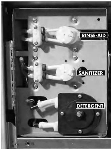
The chemical dispensing pumps are located on the bracket behind the lower-front access panel.
Installation - Model UL130
Pump Priming - Detergent, Rinse-aid and Sanitizer Dispensing Pumps
! VERY IMPORTANT !
The chemical dispensing pumps must be primed before operating the dishwasher and whenever the chemical container is changed.


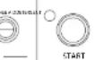

UL130 Control Panel
- Make sure the chemical containers are full and the correct pick-up tubes are in their containers.
- Turn the dishwasher power switch ON. The switch will illuminate and the dishwasher will fill with water.
- Refer to the illustration below and note the two momentary push buttons provided to prime the detergent, sanitizer and rinse aid pumps.
- Open the dishwasher door and observe the inlet chute on the rear right-hand side of the wash tank.
- Push and hold the prime push button UP to the DETERGENT position until detergent is observed entering the wash tank compartment. Release the push button.
- Push and hold the same push button DOWN until sanitizer is observed entering the wash tank compartment. Release the push button.
- Push and hold the other push button UP to the RINSE AID position until rinse-aid is observed entering the wash tank compartment. Release the push button.
- Priming is complete.
Model UL130 - Installation
Pump and Tank Fill Adjustments
! ATTENTION !
The amount of dispensed chemical is determined by the run time of the dispensing pump.

- Adjustment screws are provided for the dispensing pumps and for the wash tank fill. They are located on the right-hand side of the dishwasher behind the lower front access panel.
- Make sure the chemical containers are full and the pick-up tubes are in their proper containers.
- Turn the dishwasher power switch ON. The switch will illuminate and the dishwasher will fill with water.
- Run a normal dishwasher cycle and test chemical concentrations according to the chemical supplier's instructions.
CAUTION:
Excessive pressure to the potentiometers when adjusting can result in bent or broken adjusting screws.
- Each dispensing pump has a clearly marked adjustment screw. Turn the screw CW to
Operation - Model UL130
Operation - Model UL130
Loading Dish Racks
! VERY IMPORTANT! Prescrap and rinse wares before loading into the machine.

! VERY IMPORTANT! DO NOT OVERLOAD THE DISH RACK. LOAD ONE DISH RACK INTO THE MACHINE AT A TIME.

Load plates and glasses in a peg rack.
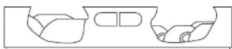
Load cups and bowls in a flat bottom rack.

Model UL130 - Operation
Operation - Model UL130
Normal Wash Mode

- Close the dishwasher front door.
- Push the dishwasher Power Switch UP to turn the power ON.
- The power switch will illuminate and the machine will fill with water.
- Wait until the wash temperature gauge indicates a minimum of 120°F/49°C.
RUN THE FIRST CYCLE WITH AN EMPTY DISH RACK TO HEAT THE WASH TANK INTERIOR.
- Load the dish rack into the machine. Wash one dish rack at a time.
- Close the door, then press the START BUTTON for 1 second. The green in-cycle light will illuminate and the wash cycle will begin. The total cycle is approximately 141 seconds.
- Opening the door during a cycle will stop the dishwasher. If the door is open more than 5 seconds the cycle will restart from the beginning, if open less than 5 seconds the cycle will resume where it left off when the dishwasher door is closed.
- The final rinse cycle begins at the end of the wash cycle. The machine drains and then refills with fresh water hot water. Check the rinse temperature gauge during the final rinse. It must indicate a minimum of 120° F/ 49° C. The final rinse water is
Operation - Model UL130
Extended Wash Mode - Model UL130
The Extended Wash Mode is used to wash heavily soiled items such as pots, pans and other wares that require more washing time than the standard Normal Wash Mode. The dishwasher will remain in the Extended Wash Mode until the operator exits the mode or 15 minutes has elapsed.
- Load a dish rack into the dishwasher, close the door and press the START button.
- The green in-cycle light will illuminate and the dishwasher will begin a normal wash cycle.
- Wait 10 seconds for the detergent to enter the wash compartment before pressing the EXT WASH button.
Press the EXT WASH button to place the machine into the extended wash mode to clean heavily soiled wares.
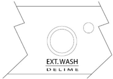
- Press the EXT WASH button to place the dishwasher in the Extended Wash Mode.
- The green extended wash light will illuminate indicating that the machine is in the Extended Wash Mode.
- The dishwasher will continue to wash for a maximum of 15 minutes or until the operator presses the EXT WASH button again whichever occurs first.
- Press the EXT WASH button. The green extended wash light will go out indicating that the dishwasher has returned to the Normal Wash Mode.
Model UL130 - Operation
Drain Mode
The dishwasher will enter the drain mode whenever the Power Switch is pushed down to the OFF/DRAIN position.
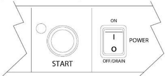
- Push the illuminated power switch down to the OFF/DRAIN position. The power switch light will go out.
- The cycle light will illuminate and the machine will drain.
- The machine, will flush, perform 3 short drain cycles and then drain completely.
- The cycle light will go out indicating that the drain cycle is complete.
! VERY IMPORTANT !
Draining Problems Related To Improper Installation.
Problems with machine draining are often the result of improper installation. The drain hose is looped and clamped as shown in the photo below and must not be changed.

Cleaning - Model UL130
Cleaning - Model UL130
! VERY IMPORTANT! DRAIN AND CLEAN THE DISHWASHER EVERY 2 HOURS OF CONTINUOUS OPERATION, AFTER EACH MEAL PERIOD, AND AT THE END OF THE DAY.
Cleaning the wash tank:
- Remove the upper and lower spray arms and flush clean in a sink.
- Remove the scrap screen taking care that debris does not fall off the screen and into the wash tank or sump. Flush the screen clean in a sink. Be sure to back-flush the screen.
- DO NOT strike the scrap screen on solid surfaces.
- Check the sump for foreign material.
Model UL130 - Cleaning
Cleaning - Model UL130 (continued)
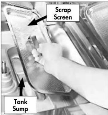
Scrap Screen and Sump Strainer
- Lift the scrap screen straight up and out of the machine to prevent food particles from falling into the tank sump.
- Flush the scrap screen in a remote sink making sure to back-flush both side of the screen.
- Wipe the tank sump of water and debris.
- Carefully inspect the sump strainer. This strainer is not removable but must be thoroughly cleaned before reinstalling the scrap screen.
! ATTENTION !
A CLOGGED SUMP STRAINER WILL PREVENT THE PROPER WASHING, RINSING AND DRAINING OF THE MACHINE.

De-liming - UL130
De-liming - Model UL130
DANGER:
Death or serious injury may result when de-liming solution is mixed with sodium hypochlorite sanitizing agent. Mixing may cause hazardous gases to form. De-liming solution and other acids must never be mixed with chlorine, iodine, bromine, or fluorine.
CAUTION:
Skin contact with de-liming solutions can cause severe irritation and possible chemical burns. Always wear eye protection, rubber gloves and protective clothing when handling chemicals.
De-lime Mode - Model UL130
The EXT. WASH/DELIME switch is used to the de-lime the machine.

Model UL130 De-liming
Follow the steps below to de-lime the UL130:
- Open the dishwasher door and remove any dish racks.
- Turn the power switch on the dishwasher to the ON position.
- Remove the detergent and rinse-aid, and sanitizer chemical supply tubing from their chemical supply containers.
- Place the tubing in a container of hot water.
- Press and hold the prime switch UP in the DETERGENT position to flush the detergent from the supply tubing. Release the switch.
- Press and hold the prime switch DOWN in the SANITIZER position to flush the sanitizer from the supply tubing. Release the switch.
- Press and hold the rinse-aid prime switch UP in the RINSE AID position to flush the rinse-aid from the supply tubing. Release the switch.
- Turn the dishwasher power switch to OFF/DRAIN to drain the wash tank. The green cycle light will go out in about 2 minutes.
- Always wear eye protection, rubber gloves and protective clothing when handling
Maintenance - Model UL130
Follow the maintenance schedules below to keep the dishwasher operating most efficiently.
Daily Maintenance
- Make sure the water supply is on and that the drain is not clogged.
- Check the temperature gauges and/or displays to ensure they are operating.
- Make sure the dish racks are in good condition.
- Check the chemical containers and refill as required.
- Follow the cleaning procedures provided in the UL130 Cleaning Section.
Weekly Maintenance
- Perform Steps 1-5 in the Daily Maintenance.
- Inspect water lines for leaks.
- Check for water leaks underneath the dishwasher.
- Make sure the flexible water fill and drain hoses are not kinked.
- Make sure that the dishwasher is level.
- Clean accumulated lime deposits from the wash tank heating element.
- Inspect the scrap screen and replace it if damaged.
- Check the spray arms and replace or repair if damaged.
Monthly Maintenance
- Perform the Daily and Weekly Maintenance listed above.
- Clean the chemical dispenser pick-up tubing for the chemical dispensing pumps.
To clean the pick-up tubing!
Troubleshooting - All Models
Troubleshooting
All Models
Illustrations
Page
Troubleshooting Chart - UH130, UH130B, UH230, UH230B 54
Wash Codes Temperature Display Board - UH130, UH130B, UH230, UH230B, UH330B .....55
Rinse Codes Temperature Display Board - UH130, UH130B, UH230, UH230B, UH330B....56
Booster Codes Temperature Display Board - UH130, UH130B, UH230, UH230B, UH330B.....57
Timer Board Connection Diagram - All Models 58
Timer Board Diagnostic Testing - UH130, UH130B, UH230, UH230B 59
Temperature Display Board Power Terminal Connections....60
Troubleshooting - UH130, UH130B, UH230, UH230B, UL130
| Condition Cause | Solution | |
| Dishwasher will not run. | Door not closed.Main power OFF.Dishwasher OFF. | Close door completely.Check breaker on panel.Turn dishwasher power switch ON. |
| Low or no water. | Main water supply off.Fill hose kinked.Low incoming water pressureSolenoid valve defective.Solenoid strainer clogged.Circuit board fuse blown. | Open supply valve.Straighten fill hose.Set flowing water pressure to 20-22 PSI.Install repair kit or replace.Clean strainer.Contact service agent.. |
| Chemicals won't feed into dishwasher. | Chemical supply low.Supply tubing damaged.Supply tubing kinked.Pick-up tube cloggedChemical circuit board fuse blown. | Refill chemical container.Replace tubing.Straighten tubing.Clean/replace tube.Contact service agent. |
| Low water pressure pumped from wash spray arms. | Clogged scrap screen.Clogged spray arms.Clogged pump intake screen. | Clean scrap screen.Clean spray arms.Inspect sump and clean pump intake screen. |
| Poor wash results. | Excessively hard water.Water temperature low.Thermistor defective.(See chemicals won't feed above.) (See low or no water above.) Detergent injector defective.Chemical circuit board fuse blown.Wares incorrectly loaded.in dishrack. | Contact chemical supplier.Raise incoming water temperature to 140°F Replace thermistor.(See chemicals won't feed above.) (See low or no water above.)Replace squeeze tube.Replace injector motor.Clean tubing and pick-up.Contact service agent.Reposition wares or reduce amount of wares in dish racks. |
UH130, UH130B, UH230, UH230B, UH330B - Digital Temperature Display Codes
Digital Temperature Display Codes
Display codes that appear in the display windows indicate the operating condition of the machine. Refer to the illustrations below for the meaning of the codes.
Wash Display Codes

Digital Temperature Display Codes - UH130, UH130B, UH230, UH230B, UH330B
Rinse Display Codes

UH130, UH130B, UH230, UH230B, UH330B - Digital Temperature Display Codes
Booster Display Codes
Error Codes for Booster and Final Rinse Thermistors Only.
DISPLAY CODES
CAUSE
150
WASH TEMP
b H
RINSE TEMP
Booster overtemp lockout because booster temperature is greater than 210°F.
NOTE: Booster is locked out for 10 minutes before being re-energized.
150
WASH TEMP RINSE TEMP
b E
Booster thermistor is defective or disconnected, broken wires.
NOTE: After the thermistor is reconnected, there is a 5 second delay before the display is re-energized.

Diagnostic Testing for the Solid State Timer Board, P/N 0712105
Beginning with S/N W081217467 and above
1
Before testing, Press the dishwasher power switch to OFF/DRAIN and allow the machine to complete the drain cycle.
Check the incoming voltages.
2
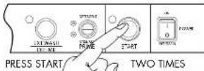
With the Power switch in the OFF/DRAIN position, press the START button 2 times.
If the drain valve opens and closes 5 times then the DRAIN VALVE is okay.
3
Open the door.
If the green cycle indicator light blinks continuously for 10 seconds, then the DOOR SWITCH and the CYCLE LIGHT are okay.
Indicator light
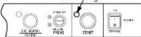
4
Press and release the START button.
If the green cycle indicator light flashes then the START BUTTON is okay.
Indicator light

5
With the Power switch in the OFF/DRAIN position, press the START button 3 times.
The timer board and the following components are okay if the components run consecutively for a few seconds in the following order:

- Fill Valve
Digital Temperature Display Board - All Models

Power Terminals.
Undecounter Temperature Dispaly Board - P/N 0512106-
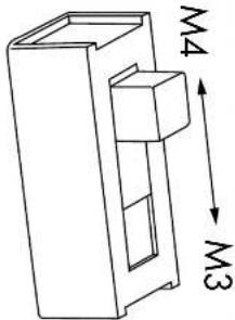
NOTE: The machine will selector switch is

UNDERCOUNTER TEMPERATURE DISPLAY BOARD - P/N 0512106 M3 - M4 MODEL SELECTOR SIDE SWITCH

Undercounter Temperature Display Board P/N 0512106-1
| A - 1 |
| open eyes for nine (r) |
| push od 17 in the window board |
| C - push indica in the window board |
| A run shout temper index is open |
| push A run temple in which is open |
| D - 1 boost is 3/4 NOT! |
| E - 1 wash 3/4 FOR |
Booster Heater/Wash Tank Heater Interlock Circuit Operation
For Models UH130B, UH230B The booster heater/wash tank heater interlock circuit removes power from the wash tank heater whenever the booster heater contactor energizes.
The illustration below shows how the booster heater contactor is wired.
The booster heater contactor is located on the center of the base behind the lower front access panel.
Interlock Circuit Operation
- The dishwasher fills with water when the main power switch on the dishwasher is turned on. The booster heater thermistor calls for heat which energizes the booster heater contactor.
- The auxiliary contact on the top of the contactor opens and removes power from the wash tank heater.
- When the booster heater thermister is satisfied, the booster heater contactor de-energizes and the auxiliary contacts close applying power to the wash tank heater.
- This operation is repeated whenever the booster thermistor calls for heat.

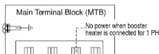
Blank Page
This Page Intentionally Left Blank
Model UH330B
Model UH330B High Temperature Undercounter Dishwasher with Heat Recovery and Built-in Booster
Installation - UH330B
Receiving - UH330B
NOTE:
The installation of your dishwasher must be performed by qualified service personnel familiar with food service equipment and must comply with all local health codes.
Problems due to improper installation are not covered by the Limited Warranty.
NOTE:
The installation of the dishwasher must comply with all local electrical, plumbing, health and safety codes or in the absence of local codes, installed in accordance with the applicable requirements in the National Electrical Code, NFPA 70, Canadian Electrical Code (CEC), Part 1, CSA C22.1; and the Standard for Ventilation Control and Fire Protection of Commercial Cooking Operations, NFPA 96.
Turn to the front of this manual and follow the instructions to register your product online or by fax.
Placement - UH330B
CAUTION:
Be careful when lifting and moving the dishwasher to prevent damage to the machine.
NOTE:
The installation of the dishwasher must comply with local health codes.
NOTE:
The dishwasher front-to-back dimension with the door open is 42-3/8" [1076 mm]. The clearance to the back wall is 2" [51mm].
![Counter-top Wall 34" [864cm] Min. 42-3/8" [1076 mm] Min. Floor 2" [51mm] Min.](/content/2026/05/925777/images/8ff2c6d0c6a985d06494596a634498e98788c313d5743ae6119a20e927ca9735.jpg)
Model UH330B - Installation
Electrical Connections - UH330B with Built-in Booster
1PH and 3PH Wiring Diagrams
! ATTENTION !
ALL DISHWASHERS ARE SHIPPED FROM THE FACTORY WIRED FOR SINGLE PHASE OPERATION UNLESS SPECIFIED AT THE TIME OF ORDER.
IF YOU ARE CONVERTING A SINGLE PHASE MACHINE TO THREE PHASE BE SURE TO FOLLOW THE BOOSTER WIRING INSTRUCTIONS ON PAGES 71-72.
Refer to the connection diagrams below to connect main incoming power to the dishwasher.
THREE PHASE POWER CONNECTION
Models UH330B
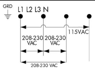
! VERY IMPORTANT !
THE ELECTRICAL POWER MUST BE A 4-WIRE PLUS GROUND SUPPLY WHICH
SINGLE PHASE POWER CONNECTION
Models UH330B
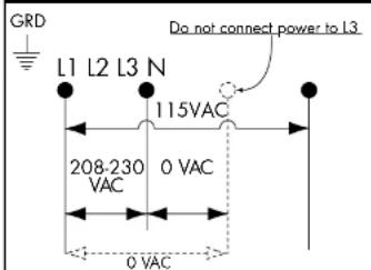
! VERY IMPORTANT !
THE ELECTRICAL POWER MUST BE A 3-WIRE PLUS GROUND SUPPLY WHICH INCLUDES A CURRENT CARRYING NEUTRAL.
Installation - Model UH330B
Connecting Incoming Power to the Main Terminal Block for 1PH and 3PH Machines with Boosters - UH330B

WARNING:
Electrocution or serious injury may result when working on an energized circuit.
Disconnect power at the main breaker or service disconnect switch before working on the circuit.
Lock-out and tag the breaker or service disconnect switch to indicate that work is being performed on the circuit.
! VERY IMPORTANT !
PROVIDE A 3 FEET/1 METER SERVICE LOOP IN THE POWER SUPPLY CABLE TO SERVICE THE DISHWASHER.
! SINGLE PHASE POWER REQUIREMENT !
SINGLE PHASE UH330B
The electrical power must be a 3-wire plus ground supply which includes a current carrying neutral.
Model UH330B - Installation
Connecting Incoming Power to the Main Terminal Block for 1PH and 3PH Machines with Boosters - UH330B
Refer to the photo below:
- Remove the lower front dishwasher panel.
- Remove the retaining fasteners (A) from the swing-out brackets and swing the chemical pump bracket (B) and the chemical circuit board bracket (C) out of the way as shown.
- Remove the screw holding the main terminal block cover and set the cover aside.

Installation Model - UH330B
UH330B - Connecting Incoming Power to the Main Terminal Block for 1PH and 3PH
Refer to the photo below:
- Provide a 3 foot/1 meter service loop in the power supply cable to service the machine
- Route the power cable from the rear of the machine to the terminal block making sure the cable does not touch the booster heater.
- Connect the power cable to the terminal block bracket using a suitable strain relief connector.
- Connect the power wires according to the wiring diagrams on page 67 for either single phase or three phase operation.
- Return the main terminal block bracket to its original position making sure the power cable does not touch the booster tank. Install the retaining screws.
- Swing the chemical pump bracket and the chemical board back into position and secure with the existing fasteners.

Booster Heater Conversion from 1PH to 3PH Operation
! VERY IMPORTANT! THE BOOSTER HEATER IS WIRED FOR 1PH OPERATION WHEN SHIPPED. FOLLOW THE INSTRUCTIONS BELOW TO WIRE THE BOOSTER FOR 3PH.
WARNING:
Electrocution or serious injury may result when working on an energized circuit.
Disconnect power at the main breaker or service disconnect switch before working on the circuit.
Lock-out and tag the breaker or service disconnect switch to indicate that work is being performed on the circuit.
- To convert the booster heater from single phase to three phase operation, locate the booster wire labeled 1H3 that is cable-tied to the booster hose.
- Remove the shrink insulation from the terminal and connect to the booster heater element as shown in the wiring diagram on page 72.

Installation - Model UH330B
Booster Heater Conversion from 1PH to 3PH Operation (continued)
! VERY IMPORTANT !
THE BOOSTER HEATER IS WIRED FOR 1PH OPERATION WHEN SHIPPED. FOLLOW THE INSTRUCTIONS BELOW TO WIRE THE BOOSTER FOR 3PH.
- Disconnect the existing booster heater wires and change the booster heater element jumpers as shown in the illustration below
- Connect wires 1H1, 1H2, and 1H3 as shown below.


Wiring Diagram - Booster heater element connections shown for 1 phase and 3 phase operation.
- A replacement 3PH data plate is stowed on the back of the lower front access panel.
- Replace the existing 1PH data plate on the front of the panel with the new 3PH data plate. Discard the 1PH data plate
Model UH330B - Installation
Completing the 1PH to 3PH Electrical Conversion
! ATTENTION! CHANGE THE DATA PLATE ON THE LOWER FRONT PANEL OF THE MACHINE
AFTER THE MACHINE IS WIRED FOR 3PH AND THE BOOSTER HEATER IS CONNECTED FOR 3PH.
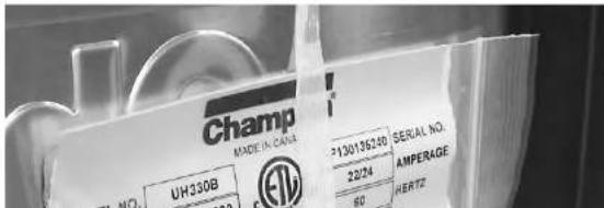
- The data plate on the dishwasher lower front panel must be changed after the machine is converted from single phase operation to three phase operation.
- Locate the replacement data plate stowed on the back of the lower front panel.
- Remove the paper backing from the label and carefully place it over the existing data plate label making sure it covers the label completely.
4 Re-install the lower front panel to complete the conversion.
Installation - Model UH330B
Water Connection - UH330B
NOTE
Plumbing connections must comply with national, provincial local plumbing and sanitary codes.
! ATTENTION! THE MODEL UH330B REQUIRES A SINGLE 1/2" INCOMING COLD WATER SUPPLY LINE
Model UH330B
- Equipped with a 6 ft. flexible cold water fill hose with a 3/4" female garden hose connector.
- A 1/2" or larger main incoming supply line must be installed to the dishwasher.
- We recommend that a 1/2" or larger shut-off valve be installed in the main water supply, as close to the dishwasher as possible for servicing.
- The UH330B has a built-in flow control. The flowing incoming cold water supply pressure must be between 25-95 psi.
- A water hardness of 3 grains/gal (US) [51.3 mg/L] or less is recommended.


! VERY IMPORTANT! IMPROPER INSTALLATION OF MACHINE DRAIN HOSE.
Machine drain problems are often the result of improper installation and may not be covered by the limited warranty.
! VERY IMPORTANT !
Do not connect the drain hose to a disposer. The dishwasher will not drain correctly.
! IMPORTANT !
Make sure that the flexible water supply and drain hoses are not kinked.
- The UH330B is a pumped drain and is equipped with a 6 ft.. 5/8" I.D. drain hose. The maximum drain height connection must not exceed 3 ft.[1 m].
- The drain hose is located at the rear of the dishwasher, and is secured to the rear of the machine provide an anti-siphoning loop in the drain hose.
- A 3/4" hose barb fitting is strapped to the drain hose prior to shipment. The service part number for the hose barb is P/N 0512321.
- Additional plumbing parts must be supplied by the plumbing installer.
- The maximum drain flow is 15 US gpm/12.4 imp gpm/60 lpm.
Installation - Model UH330B
Drain Connection - Model UH330B (continued) -
NOTE
Plumbing connections must comply with national, provincial local plumbing and sanitary codes.
DO NOT CONNECT THE DRAIN HOSE TO A DISPOSER.
DO NOT REDUCE THE SIZE OF THE DRAIN HOSE CONNECTION.
DO NOT ADD ADDITIONAL LENGTH TO THE DRAIN HOSE.
DO NOT ALLOW THE DRAIN HOSE TO KINK.
For a Direct Drain Connection:
- Install the drain hose to an 1-1/2" or larger "WYE" vented drain fitting.
- CONNECTION TO A "TEE" FITTING WILL PREVENT THE DISHWASHER FROM DRAINING COMPLETELY.

DO
connect the dishwasher flexible drain hose to a WYE drain fitting.

DO NOT
connect the dishwasher flexible drain hose to a TEE drain fitting.
Chemical Connections - Model UH330B
! VERY IMPORTANT !
ALWAYS USE A COMMERCIAL-GRADE NON-CHLORINATED DETERGENT.
PLACE THE CHEMICAL SUPPLY CONTAINERS AS CLOSE TO THE MACHINE AS POSSIBLE.
DO NOT ELEVATE THE CHEMICAL CONTAINERS ABOVE THE FINISHED FLOOR.
! VERY IMPORTANT!
Contact a chemical supplier for detergent and rinse-aid chemicals. The chemical supplier must adjust the chemical dispensing pumps for water hardness and food soil types.
Chemical Dispensing Pumps
- The detergent and rinse-aid pumps are located on the lower left-side of the machine behind the lower-front access panel.
- Each pump is equipped with 6 feet [1.8 m] of pick-up tubes consisting of supply tubing, stiffener tubes, and strainers.
- The pick-up tubes are stowed on the back of the machine for shipping.
- A red label marked DETERGENT and a blue label marked RINSE-AID identify the chemical lines.
- The chemical squeeze tubes should be inspected and replaced every six months.


Installation - Model UH330B
Chemical Connections - Model UH330B (continued)
! VERY IMPORTANT !
ALWAYS USE A COMMERCIAL-GRADE NON-CHLORINATED DETERGENT.
PLACE THE CHEMICAL SUPPLY CONTAINERS AS CLOSE TO THE MACHINE AS POSSIBLE.
DO NOT ELEVATE THE CHEMICAL CONTAINERS ABOVE THE FINISHED FLOOR.
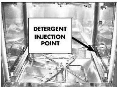
Chemical Injection Points
- The detergent enters the wash tank compartment through a fitting at the right rear of the wash compartment.
- Rinse-aid enters the final rinse through a fitting in the front of the booster tank.
Model UH330B - Installation
Chemical Connections - Model UH330B
Priming the Dispensing Pumps
! VERY IMPORTANT !
The chemical dispensing pumps must be primed before operating the dishwasher and whenever the chemical container is changed.

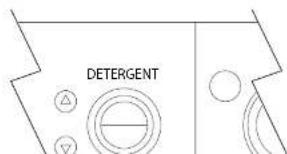
UH330B Control Panel
- The chemical dispensing pump supply lines must be primed before they will pump the chemicals properly.
- Make sure the chemical containers are full and the correct pick-up tubes are in their containers.
- Turn the dishwasher power switch ON. The switch will illuminate and the dishwasher will fill with water.
Installation - Model UH330B
Detergent and Rinse-aid Dispensing Pump Adjustments - Model UH330B
Chemical Dispensing Pump Adjustments
! ATTENTION !
The amount of dispensed chemical is determined by the run time of the dispensing time.
Refer to the photo below:
- The chemical dispensing pump run adjustment screws are located on the end of the chemical circuit board swing-out bracket.
- It is not necessary to swing the bracket out to make adjustments, but if desired, remove the mounting nut (A) and swing the bracket (B) out and to the right.
- Refer to the next page for adjustment instructions.

Installation - Model UH330B
Detergent and Rinse-aid Dispensing Pump Adjustments - Model UH330B
Chemical Dispensing Pump Adjustments (continued)
! ATTENTION! THE FILL AND SANITIZER ADJUSTMENT SCREWS ARE NOT USED ON THE UH330B MACHINE.
Refer to the photo below:
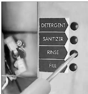
To adjust the amount of chemicals dispensed by the pumps:
-
Make sure the chemical containers are full and the pick-up tubes are in their proper containers.
-
Turn the dishwasher power switch ON. The switch will illuminate and the dishwasher will fill with water.
-
Run a normal dishwasher cycle and test detergent and rinse-aid concentrations according to the chemical supplier's instructions.
Operation - Model UH330B
Operation - Model UH330B
Loading Dish Racks
! VERY IMPORTANT! DO NOT OVERLOAD THE DISH RACK. LOAD ONE DISH RACK INTO THE MACHINE AT A TIME.
- Prescrap and rinse the wares before loading to remove large food particles.
- Load soiled wares into the dish rack. Place plates and glasses in a peg rack. Place cups and bowls in a flat bottom rack. Place utensils in a single layer in a flat-bottom rack. Place pots and pans in a flat-bottom rack.
Do not overload the dish rack. Wash one dish rack at a time.
- Slide one dish rack into the wash compartment making sure that wares do not interfere with the rotating spray arms. Do not wash more than one dish rack at a time.
Prescrap and rinse wares before loading into the machine.

Model UH330B - Operation
Loading Dish Racks (continued)

Load pots and pans in a flat-bottom rack.

Load utensils in a single layer in a flat-bottom rack.

Load cups and bowls in a flat-bottom rack.
Operation - Model UH330B
Operation - Model UH330B
UH330B Control Panel
The illustration below shows the operator controls and temperature displays for the UH330B.

Wash Mode
- Close the door.
- Push the dishwasher ON-OFF/DRAIN switch UP to turn the power ON.
- The power switch will illuminate and the machine will fill with water.
- Wait approximately 30 minutes until the wash temperature gauge indicates a minimum of 150° F/66°C.
- Scrap the wares to remove large food particles.
- Load the dish rack into the machine. Wash one dish rack at a time.
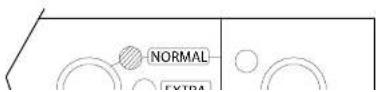
Push the Cycle button once for Extra Cycle. Push twice for Heavy Cycle.
Model UH330B - Operation
Operation - UH330B
Wash Mode (continued)
- The HEAVY cycle is selected by pushing the cycle button twice. The HEAVY green indicator light will flash for 15 seconds. Pressing the START button before the flashing HEAVY indicator light stops flashing starts the heavy wash cycle of approximately 4-1/2 minutes long. The HEAVY green indicator light will come on and the green indicator light above the start switch will illuminate indicating the machine is in the wash mode.
- Opening the door during a cycle will stop the dishwasher. The cycle will resume automatically if the dishwasher door is closed within 5 seconds. If the door is open for more than 5 seconds the cycle will start from the beginning of the cycle.
- The final rinse cycle begins at the end of the wash cycle. The machine drains and retains a portion of the final rinse water for the next wash cycle.
- Check the rinse temperature gauge during the final rinse. It must indicate a minimum of 180-195° F/82-91°C. The final rinse water is retained for the next wash cycle.
- When the green cycle light goes out, open the door and remove the rack of clean wares.
! ATTENTION !
DOOR LEFT OPEN DURING WASH CYCLE
If the dishwasher door is left open for more than 5 seconds during the wash mode, the dishwasher cycle will reset to the beginning of the selected wash cycle.
Operation - Model UH330B
Operation - Model UH330B
! VERY IMPORTANT !
Draining Problems Related To Improper Installation.
Problems with machine draining are often the result of improper installation.
NEVER EXTEND OR ADD LENGTH TO THE DRAIN HOSE.
Drain Mode
The dishwasher will enter the drain mode whenever the ON-OFF/DRAIN power switch is pushed down to the OFF/DRAIN position. The switch is located on the left side of the control panel.
IF THE ON-OFF/DRAIN SWITCH IS PLACED IN THE OFF/DRAIN POSITION FOR MORE THAN 3 SECONDS, THE DISHWASHER WILL CONTINUE TO DRAIN EVEN IF THE SWITCH IS PUSHED BACK TO THE ON POSITION.
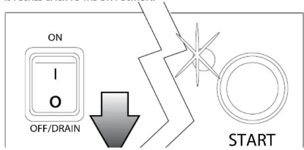
Model UH330B - Cleaning
Cleaning - Model UH330B
! VERY IMPORTANT! DRAIN AND CLEAN THE DISHWASHER EVERY 2 HOURS OF CONTINUOUS OPERATION, AFTER EACH MEAL PERIOD, AND AT THE END OF THE DAY.
! ATTENTION! DO NOT USE STEEL WOOL SCRUB PADS TO CLEAN THE MACHINE. DO NOT SPRAY THE EXTERIOR OF THE MACHINE WITH WATER.
To clean your machine:
- Open the door and remove any dish rack inside the machine.
- Drain the machine according to the instructions on the previous page.
- Refer to the photo below. Remove the upper and lower wash and rinse arms.
- Clean the overflow guard by hand with it installed in the machine.

Cleaning - Model UH330B
Cleaning - Model UH330B
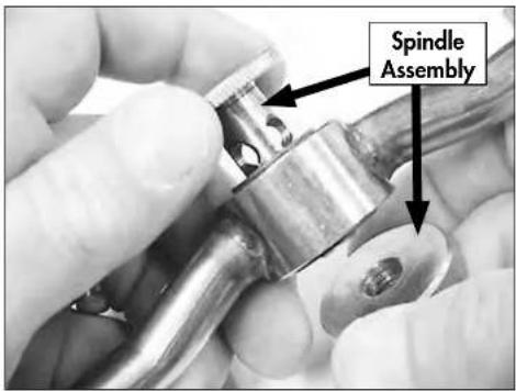
Rinse Arms
- There are two rinse arms. They are interchangeable.
- Remove the spindle assembly and end plugs in each pipe and flush the rinse pipes.
- Inspect the rinse arm bearings for wear and replace as necessary.
- Clean the rinse arm nozzles with a small paper clip.
- Reassemble the rinse arm assemblies.

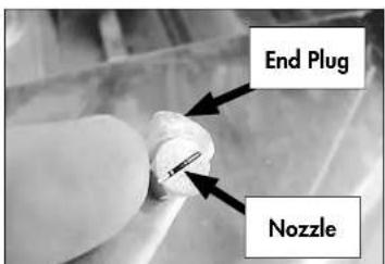
Model UH330B - Cleaning
Model UH330B - Cleaning
Scrap Screen and Sump Strainer
- Lift the scrap screen straight up and out of the machine to prevent debris from falling into the tank sump.
- Flush the scrap screen in a remote sink making sure to back-flush both sides of the screen.
- Wipe the tank sump of water and debris.
- Carefully inspect the sump strainer. This strainer is not removable but must be thoroughly cleaned before reinstalling the scrap screen.


! ATTENTION! A CLOGGED OR RESTRICTED SUMP STRAINER WILL PREVENT THE PROPER WASHING, RINSING AND
De-liming Cautions and Warnings
A de-liming agent must be used in accordance with your chemical supplier's instructions.
DANGER:
Death or serious injury may result when de-liming solution is mixed with sodium hypochlorite sanitizing agent. Mixing may cause hazardous gases to form. De-liming solution and other acids must never be mixed with chlorine, iodine, bromine, or fluorine.
CAUTION:
Skin contact with de-liming solutions can cause severe irritation and possible chemical burns. Always wear eye protection, rubber gloves and protective clothing when handling chemicals.
Follow the procedures below to de-lime the UH330B dishwasher.
- Open the dishwasher door and remove any dish racks.
- Turn the power switch on the dishwasher to the ON position.
- Remove the detergent and rinse-aid chemical supply tubing from their chemical supply containers.
- Place the tubing in a container of hot water.
- Press and hold the prime switch UP in the DETERGENT position to flush the detergent from the supply tubing. Release the switch.
- Press and hold the prime switch DOWN in the RINSE AID position to flush the rinse-aid from the supply tubing. Release the switch.
- Turn the dishwasher power switch to OFF/DRAIN to drain the wash tank. The green cycle
Model UH330B - Maintenance
Follow the maintenance schedules below to keep the dishwasher operating efficiently.
Daily Maintenance
- Make sure the water supply is on and that the drain is not clogged.
- Check the temperature displays to ensure they are operating.
- Make sure the dish racks are in good condition.
- Check the chemical containers and refill as required.
- Follow the cleaning procedures provided in the Cleaning Section.
Weekly Maintenance
- Perform Steps 1-5 in the Daily Maintenance.
- Inspect water lines for leaks.
- Check for water leaks underneath the dishwasher.
- Make sure the flexible water fill and drain hoses are not kinked.
- Make sure that the dishwasher is level.
- Clean accumulated lime deposits from the wash tank heating element.
- Inspect the scrap screen and replace it if damaged.
- Check the spray arms and replace or repair if damaged.
Monthly Maintenance
- Perform the Daily and Weekly Maintenance listed above.
Troubleshooting - UH330B
Troubleshooting - UH330B
| Condition Cause Solution | ||
| Dishwasher will not run. | Door not closed.Main power OFF.Dishwasher OFF.Circuit board fuse blown. | Close door completely.Check breaker on panel.Turn dishwasher power switch ON.Contact service agent. |
| Low or no water. | Main water supply off.Fill hose kinked.Low incoming water pressureSolenoid valve defective.Solenoid strainer clogged. | Open supply valve.Straighten fill hose.Set flowing water pressure to 25-95 PSI.Install repair kit or replace.Clean strainer. |
| Chemicals won't feed into dishwasher. | Chemical supply low.Supply tubing damaged.Supply tubing kinked.Pick up tube cloggedChemical circuit board fuse blown.Pump squeeze tube defective. | Refill chemical container.Replace tubing.Straighten tubing.Clean/replace tube.Contact service agent.Replace squeeze tube. |
| Low water pressure pumped from wash spray arms. | Clogged scrap screen.Clogged spray arms.Clogged pump intake. | Clean scrap screen.Clean spray arms.Inspect sump and clean pump intake. |
| Poor wash results. | Excessively hard water.Thermistor defective.(See chemicals won't feed above.) (See low or no water above.) Detergent injector defective.Chemical circuit board fuse blown.Wares incorrectly loaded.in dishrank. | Contact chemical supplier.Replace thermistor.(See chemicals won't feed above.) (See low or no water above.)Replace squeeze tube.Replace injector motor.Clean tubing and pick-up.Contact service agent.Reposition wares or reduce amount of wares in dish racks. |
Follow the instructions below to quickly check the status of many machine components.
! ATTENTION !
Refer to pages 55-63 for additional troubleshooting information.
d Self-Diagnostic Test
| A ACTION | REACTION OBSERVED | OPERATIONAL | |
| Power Switch in DRAIN position, START button | drain valve opens and closes 5 times. | drain valve | √ |
| or | green cycle light blinks | door switch, cycle light | √ |
| I release START | green cycle light blinks | start button | √ |
| or and t switch Components on will run vely for a nds. | fill valve opens | fill valve | √ |
| detergent pump runs | detergent pump | √ | |
| rinse-aid pump runs | rinse-aid pump | √ | |
| drain valve opens | drain-valve | √ | |
| drain valve closes | |||
| wash pump runs | wash pump | √ | |
| drain pump / sanitizer runs | drain pump / sanitizer | √ |
onents do not run, see below:
Blank Page
This Page Intentionally Left Blank
Service Replacement Parts
Illustrations
Page
Wash Pump/Motor Assembly - All Models 96
Base Assembly - All Models....98
Fill Piping Assembly - UH130, UH130B, UL130, UH330B 102
Fill Solenoid Valve - UH130, UH130B, UL130, UH330B 104
Fill Piping Assembly - UH230, UH230B....106
Fill Rinse Piping Assembly - UH230, UH230B....108
Final Rinse Piping - UH330B....110
Heat Recovery Assembly - UH330B....112
Booster and Pressure Switch Assemblies - UH330B....114
Fill Chute Assembly - UH130, UH130B, UL130....116
Chemical Dispensing Pumps - UH130, UH130B, UH230, UH230B 118
Chemical Dispensing Pumps - UH330B....120
Chemical Dispensing Pumps - UL130....122
Booster Assembly - UH130B, UH230B 124
Power Input Block and Cord Assemblies - All Models....126
Timer Control Board Assembly - All Models 128
Wash and Rinse Spray Arms and Drain Valve - UH230, UH230B, UH330B 130
Wash Pump/Motor Assembly - All Models

All Models - Wash Pump/Motor Assembly
| Item No. | Part No. | Description | Qty. | ||
| 1 | 0512347 | CAPACITOR 40μF 1 | |||
| 2 | 0512101 | PUMP/MOTOR ASSEMBLY COMPLETE 1115VAC/60/1 | |||
| 3 | 0313394 | BRACKET, WASH PUMP 1 | |||
| 4 | 0512185 | BOLT, HEX FLANGE 1/4-20 X 3/8" SST 2 | |||
| 5 | 110285 | GASKET | 1 | ||
| 6 | 114139 | SEAL | 1 | ||
| 7 | 0512345 | IMPELLER | 1 | ||
| 8 | 0501478 | WASHER, PLAIN, 17/64" | 1 | ||
| 9 | 106482 | WASHER, LOCK, 1/4" | 1 | ||
| 10 | 114144 | NUT, M6 | 1 | ||
| 11 | 0512340 | SCREW, M4, PHIL, PAN HD. | 9 | ||
| 12 | 0512341 | VOLUTE, PUMP | 1 | ||
| 13 | 114137 | BACKPLATE, PUMP | 1 | ||
| 14 | 107337 | NUT, M4 | 9 | ||
| 15 | 0513131 | COVER, REAR MOTOR FAN | 1 |
NOTE: The pump motor is not sold separately.
Base Assembly - All Models
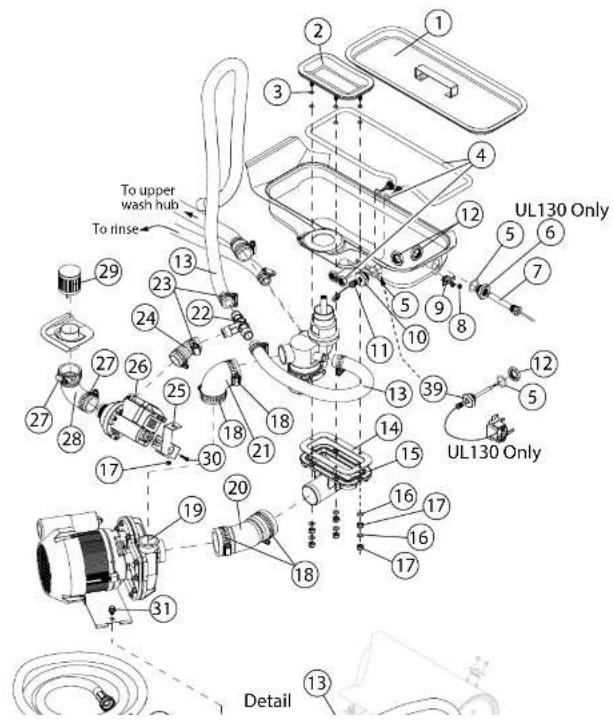
All Models - Base Assembly
| Item No. | Part No. | Description | Qty. | |
| 1 | 0512136 | SCREEN, SCRAP ASSY. 1 | ||
| 2 | 0513324 | FLANGE, PUMP SUCTION 1 | ||
| 3 | 0513677 | O-RING | A/R | |
| 4 | 0512169 | HEATER, 120VAC 750W) {UL130} 1 | ||
| - | 0512426 | HEATER, 240VAC 2000W (All except UL130) 1 | ||
| 5 | 0512099 | O-RING | 1 | |
| 6 | 0508872 | ADAPTOR, THERMOMETER (UL130 Only) 1 | ||
| 7 | 0512107 | THERMOMETER, WASH TANK (UL130 Only) | ||
| 8 | 108954 | NUT, GRIP 6-32 WITH NYLON INSERT SST | 2 | |
| 9 | 113604 | THERMOSTAT, HI-LIMIT BI-METAL SNAP, 212°F | 1 | |
| 10 | 0512299 | ADAPTOR, THERMISTOR | 1 | |
| 11 | 0513310 | THERMISTOR, 10 KΩ, 2 WIRE ASSY, WASH TANK{All except UL130} | 1 | |
| 12 | 201029-1 | NUT, LOCK 1/2 INCH NI PLATED | ||
| 13 | 0509302 | HOSE, 5/8" ID X 1" OD X 6" LG. | A/R | |
| 14 | 0513329 | GASKET, PUMP SUCTION | 1 | |
| 15 | 0513324 | ELBOW, PUMP SUCTION | 1 | |
| 16 | 0501476 | WASHER |
All Models - Base Assembly
| Item No. | Part No. | Description | Qty. | |
| 26 | 0512227 | PUMP, DRAIN 115VAC (UH230, UH230B, UH330B) | 1 | |
| 27 | 0512322 | CLAMP, HOSE 2 | ||
| 28 | 0513339 | HOSE, OVERFLOW (UH230, UH230B, UH330B) | 1 | |
| 29 | 0712236 | TUBE, OVERFLOW GUARD (UH230, UH230B) | 1 | |
| — | 0712236-1 | TUBE, OVERFLOW GUARD (UH330B ONLY) | 1 | |
| 30 | 109835 | SCREW #8 X 1/2" SELF-TAPPING SST 1 | ||
| 31 | 0512185 | BOLT, HEX FLANGE 1/4-20 X 3/8" SST 1 | ||
| 32 | 0509526 | HOSE, 1/2" X 7 FT. FEM. GARD. ADAPT. 1 | ||
| 33 | 0504952 | VALVE, FILL 5.0 GPM (UH130, UH130B, UL130) | 1 | |
| — | 0513557 | VALVE, FILL 1.0 GPM (UH330B Only) | 1 | |
| 34 | 109886 | VALVE, SOLENOID, 1/2" NPT (UH230, UH230B) | 1 | |
| 35 | 0501379 | SWITCH, 15A | 1 | |
| 36 | 0512792 | SCREW, 10-32 X 1/4" RD. HD. PHILL. SST | 2 | |
| 37 | 0508752 | SCREW, 4-40 X 5/8" RH. HD. PHILL. SST | 2 | |
| 38 | 0313432 | BRACKET, DOOR SWITCH | 1 | |
| 39 | 0507323 | THERMOSTAT, WASH (UL130 Only) | 1 |
Blank Page
This Page Intentionally Left Blank
Fill Piping Assembly - UH130, UH130B, UL130, UH330B

UH130, UH130B, UL130, UH330B - Fill Piping Assembly
| Item No. | Part No. | Description | Qty. |
| 1 | 0502653 | ELBOW, 90" 3/8" MPT X 1/2" HOSE 1 | |
| 2 | 0512185 | BOLT, HEX FLANGE 1/4-20 X 3/8" SST 4 | |
| 3 | 0300065 | SUPPORT, VALVE 1 | |
| 4 | 0300203 | CLAMP, VALVE 1 | |
| 5 | 0502618 | HOSE BARB, 1/2" X 3/8" MPT 1 | |
| 6 | 0512985 | CLAMP, HOSE 1 | |
| 7 | 0509526 | HOSE, 1/2" X 7 FT. FEM. GARD. ADAPT. 1 | |
| 8 | 0505320 | WASHER, 1" OD GARDEN HOSE 1 | |
| 9 | 0504952 | VALVE, FILL, 3/8" NPT 1 | |
| — | 0513557 | VALVE, FILL 1.0 GPM (UH330B ONLY) | 1 |
Fill Solenoid Valve - UH130, UH130B, UH330B, UL130

UH130, UH130B, UH330B, UL130 - Fill Solenoid Valve
| Item No. | Part No. | Description | Qty. |
| 1 | 0504952 | VALVE, FILL 5.0 GPM (EXCEPT UH330B) 1 | |
| - | 0513557 | VALVE, FILL 1.0 GPM (UH330B ONLY) 1 | |
| 2 | 0502803 | SCREEN, VALVE STRAINER 1 | |
| 3 | 0502804 | GASKET, CAP 1 | |
| 4 | 0504958 | WASHER, FLOW 5.0 GPM (EXCEPT UH330B) 1 | |
| - | 0513674 | WASHER, FLOW 1.0 GPM (UH330B ONLY) 1 | |
| 5 | 0502811 | KIT, REBUILD 1 | |
| 6 | 0505229 | GUIDE 1 | |
| 7 | 0501406 | SCREW, SLOT SS RH 8-32 X 1/2" 3 | |
| 8 | 0505235 | COIL, 115V 60HZ 10W | 1 |
| 9 | 0502807 | GASKET, OUTLET (COPPER) | 1 |
Fill Piping Assembly - UH230, UH230B

UH230, UH230B - Fill Piping Assembly
| Item No. | Part No. | Description | Qty. | |
| 1 | 0512985 | CLAMP, HOSE 2 | ||
| 2 | 0508782 | ELBOW, 90° 1/2" MPT X 1/2" HOSE 1 | ||
| 3 | 0312146 | BRACKET, 1/2" SOLENOID VALVE 1(UH230, UH230B) | ||
| 4 | 0512185 | BOLT, HEX FLANGE 1/4-20 X 3/8" SS 2 | ||
| 5 | 0502618 | BARB, HOSE 1/2" X 3/8" MPT 1 | ||
| 6 | 0509526 | HOSE, 1/2" X 7 FT. FEM. GARD. ADAPT. | 1 | |
| 7 | 0505320 | WASHER, 1" OD GARDEN HOSE 1 | ||
| 8 | 109886 | VALVE, SOLENOID, 1/2" NPT 120VAC | 1 | |
| 9 | 109902 | KIT, REPAIR, 1/2" SOLENOID VALVE | 1 | |
| 10 | 108516 KIT, REPAIR, COIL, 120VAC | 1 | ||
| 11 | 107417 HOSE, RUBBER 1/2" ID X .84" OD | A/R |
Upper Final Rinse Piping - UH230, UH230B

UH230, UH230B - Upper Final Rinse Piping
| Item No. | Part No. | Description | Qty. |
| 1 | 0502571 | CLAMP, HOSE 1 | |
| 2 | 0512120 | HOSE, UPPER WASH 1 | |
| 3 | 0512985 | CLAMP, HOSE A/R | |
| 4 | 107417 | HOSE, RUBBER 1/2" ID X .84" OD A/R | |
| 5 | 0512757 | CONDUIT, 1/2" A/R | |
| - | 0512758 | CONDUIT, 3/8" A/R | |
| 6 | 0512369 | CLAMP, CONDUIT 4 | |
| 7 | 112728 | FITT COMP 1/4" OD X 1/8" MPT ELL J 1 | |
| 8 | 112883-1 | TUBING, 1/8" OD X 1/16" ID (RINSE-AID) A/R | |
| 9 | 0502667 | TUBING, 1/4" ID X 3/8" OD (DETERGENT) | A/R |
| 10 | 0502651 COUPLER 1/2" MPT X 1/2" HOSE | 1 | |
| 11 | 0312190 BRACKET, VACUUM BREAKER | 1 | |
| 12 | 100003 NUT, HEX SST 1/4-20 | 2 | |
| 13 | 106482 WASHER, SPLIT LOCK 1/4" SST | 2 | |
| 14 | 201029-1 NUT, LOCK 1/2" NICKEL PLATED | 1 | |
| 15 | 100500 VACUUM BREAKER, 1/2" NPT, BRONZE | 1 | |
| — | 900836 REPAIR KIT, VACUUM BREAKER 1/2" | 1 | |
| 16 | 0508817 PLUG, 1/8" HEX COUNTERSUNK A/R |
Final Rinse Piping - UH330B
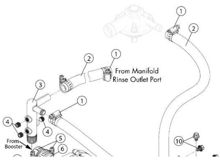
UH330B - Final Rinse Piping
| Item No. | Part No. | Description | Qty. |
1 0512985 CLAMP, HOSE A/R
2 107417 HOSE, RUBBER 1/2" ID X .84" OD A/R
3 0513110 MANIFOLD, RINSE 1
4 0508817 PLUG, 1/8" HEX COUNTERSUNK 3
5 0508817 CLAMP 2
6 0513679 HOSE, 1" ID X 1-3/8" BRAIDED 1
7 0513734 HOSE, MOLDED, RINSE DISCHARGE 1
8 115231 PUMP/MOTOR, RINSE 1
9 0313610 BRACKET, RINSE PUMP 1
10 0512185 BOLT, HEX FLANGE 1/4-20 X 3/8" SST 2
Heat Recovery Assembly - UH330B
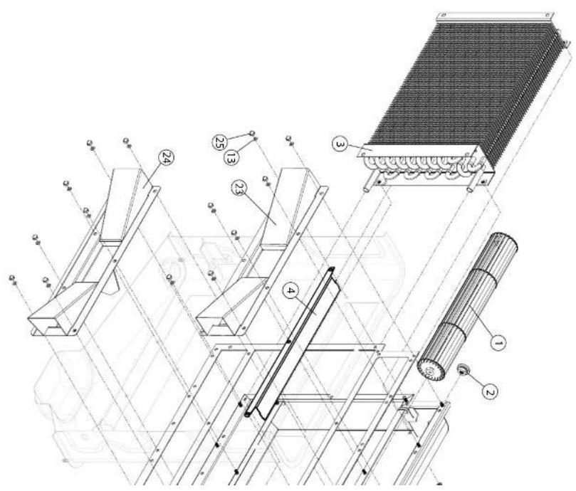
UH330B - Heat Recovery Assembly
| Item No. | Part No. | Description | Qty. | |
| 1 | 0513572 | BLOWER | 1 | |
| 2 | 0513574 | BEARING (COMES WITH RUBBER HSG.) 2 | ||
| 3 | 0513571 | COIL, HEAT RECOVERY 1 | ||
| 4 | 0313599 | DEFLECTOR, FAN AIR 1 | ||
| 5 | 0313594 | MOUNT, FAN MOTOR 1 | ||
| 6 | 0513733 | SEAL, V-RING 1/4" 2 | ||
| 7 | 0503580 | NUT, 10-32 SST A/R | ||
| 8 | 0513573 | MOTOR, BLOWER 115VAC 1 | ||
| 9 | 0513732 | SEAL, V-RING 1/2" 2 | ||
| 10– 900836 | 100500 | BREAKER, VACUUM 1REPAIR KIT, VACUUM BREAKER 1/2" | A/R | |
| 11 | 0508782 | ELBOW, 1/2" X 1/2" HOSE BARB 1 | ||
| 12 | 0512985 | CLAMP, HOSE | 4 | |
| 13 | 0507709 | WASHER | A/R | |
| 14 | 0513648 | ELBOW, 1/2" HOSE | 2 | |
| 15 | 107417 | HOSE, RUBBER 1/2" ID X .84" OD | A/R | |
| 16 | 100003 | NUT, HEX 1/4-20 SST | 2 | |
| 17 | 106482 | WASHER, SPLIT LOCK 1/4" SST | 2 | |
| 18 | 0502651 | COUPLER, 1/2" MPT X 1/2" HOSE | 1 |
Booster and Pressure Switch Assemblies - UH330B

Booster and Pressure Switch Assemblies - UH330B
| Item No. | Part No. | Description | Qty. | |
| 1 | 109835 | SCREW, #8 X 1/2" PAN HD. PHIL. SST 4 | ||
| 2 | 0503580 | NUT 10-32 SST 4 | ||
| 3 | 0507709 | WASHER, FLAT #10 SST 4 | ||
| 4 | 0313587 | BRACKET, PRESSURE SWITCH 2 | ||
| 5 | H31171 | SWITCH, PRESSURE 2 | ||
| 6 | H160121 | HOSE, EPDM A/R | ||
| 7 | 0513731 | ELBOW, 1/4 NPT X 1/2" HOSE (C/W NUT) 1 | ||
| 8 | 0713565 | TANK, BOOSTER | 1 | |
| 9 | 0512985 | HOSE, CLAMP | A/R | |
| 10 | 107417 HOSE, RUBBER 1/2" ID X .84" OD | A/R | ||
| 11 | 0513650 ADAPTER, 1/2" X 1/4" HOSE | 2 | ||
| 12 | 0508782 ELBOW, 1/2" NPT X 1/2" HOSE | 2 | ||
| 13 | 0513310 THERMISTOR, 10 KΩ, 2-WIRE 1 | |||
| 14 | 0512185 BOLT, HEX FLANGE 1/4-20 X 3/8" SST | 2 | ||
| 15 | 0508817 PLUG, 1/8" | 1 | ||
| 16 | 108954 | NUT, GRIP 6-32 W/NYLON INSERT | 2 | |
| 17 | 110562 THERMOSTAT, HIGH LIMIT 240°F | 1 | ||
| 18 | 109985 SEAL, ELEMENT BOOSTER | 1 | ||
| 19 | 0513654 BOOSTER. ELEMENT 3.5 KW | 1 |
Fill Chute Assembly - UH130, UH130B, UL130

UH130, UH130B, UL130 - Fill Chute Assembly
| Item No. | Part No. | Description | Qty. | |
| 1 | 107417 | HOSE, RUBBER 1/2" ID X .84" OD A/R | ||
| 2 | 0502666 | HOSE, 1/8" ID X 1/4" OD PVC A/R | ||
| 3 | 0502667 | HOSE, 1/4" ID X 3/8" OD PVC A/R | ||
| 4 | 100194 | NUT, GRIP 10:32 W/NYLON INSERT 2 | ||
| 5 | 0503722 | NUT, HEX 10:32 SST 4 | ||
| 6 | 0507709 | WASHER, FLAT #10 SST 4 | ||
| 7 | 0508867 | CHUTE, INLET 1 | ||
| 8 | 0509048 | GASKET, INLET CHUTE 1 | ||
| 9 | 0308822 | CLAMP, EMT 1/2" | 1 | |
| 10 | 0509302 HOSE, 5/8" ID X 1" OD PVC BRAIDED | A/R | ||
| 11 | 0306363 TUBE, STIFFENER | A/R | ||
| 12 | 0501869 | STRAINER | A/R | |
| 13 | 0509526 HOSE, FILL 1/2" X 7 FT. FEM. GARD. ADAPT. | 1 | ||
| 14 | 0503695 LABEL, DETERGENT HOSE | 1 | ||
| 15 | 0505483 LABEL PINSE-AID HOSE 1 |
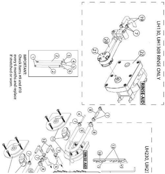
UH130, UH130B, UH230, UH230B - Chemical Dispensing Pumps
| Item No. | Part No. | Description | Qty. | |
| 1 | 0501869 | STRAINER | 2 | |
| 2 | 0306363 | TUBE, 3/8" ID X 12" LG. STIFFENER 1 | ||
| 3 | 0505483 | LABEL, RINSE-AID HOSE 1 | ||
| 4 | 112883-1 | TUBING, 1/8" OD X 1/16" ID A/R | ||
| 5 | 0503695 | LABEL, DETERGENT HOSE A/R | ||
| 6 | 0502667 | HOSE, 1/4" ID X 3/8" OD PVC A/R | ||
| 7 | 0501519 | TIE, NYLON 4" 9 | ||
| 8 | 0512369 | CLAMP, HOSE | 2 | |
| 9 | 112759 | TUBE, PUMP 1/8" ID X 9" LG. 1 | ||
| 10 | 114202 | TUBE, PUMP 3/16" ID X 3/8" OD X 9" LG. | 1 | |
| 11 | 114203 | PUMP HD KIT, PERISTALIC 2 | ||
| 12 | 0502644 | ELBOW, 1/4" HOSE BARB | 2 | |
| 13 | 100007 | SCREW, 10-32 X 3/8" TRUSS SST | 3 | |
| 14 | 0313644 | PIN, HINGE | 1 | |
| 15 | 0513645 | HOLDER, CABLE | 4 | |
| 16 | 0313393 | BRACKET, CHEMICAL PUMP | 1 | |
| 17 | 0510870-1 | GEARMOTOR, 115/60/1 | 2 |
Chemical Dispensing Pumps - UH330B

UH330B - Chemical Dispensing Pumps
| Item No. | Part No. | Description | Qty. | |
| 1 | 0501869 | STRAINER | 2 | |
| 2 | 0306363 | TUBE, 3/8" ID X 12" LG. STIFFENER 1 | ||
| 3 | 0505483 | LABEL, RINSE-AID HOSE 1 | ||
| 4 | 0502666 | HOSE, 1/8" ID X 1/4" OD PVC A/R | ||
| 5 | 0503695 | LABEL, DETERGENT HOSE A/R | ||
| 6 | 0502667 | HOSE, 1/4" ID X 3/8" OD PVC A/R | ||
| 7 | 0501519 | TIE, NYLON 4" 7 | ||
| 8 | 0706635 | TUBE, ELEMENT ASSEMBLY 45CC 1 | ||
| 9 | 0707142 | ROTOR | 1 | |
| 10 | 0503756 | MOTOR, INJECTOR PUMP | 1 | |
| 11 | 0502644 | ELBOW, 1/4" HOSE BARB | 2 | |
| 12 | 0502667 | HOSE, 1/4" ID X 3/8" OD PVC A/R | ||
| 13 | 0512369 | CLAMP, HOSE | 1 | |
| 14 | 114202 | TUBE, 3/16" ID X 3/8" OD X 9" LG. | 1 | |
| 15 | 114203 | PUMP HD KIT, PERISTALIC 1 | ||
| 16 | 100007 | SCREW, 10-32 X 3/8" TRUSS SST | 3 | |
| 17 | 0504822 | SCREW, 8-32 X 1/2" PAN HD. SST | 4 | |
Chemical Dispensing Pumps - UL130
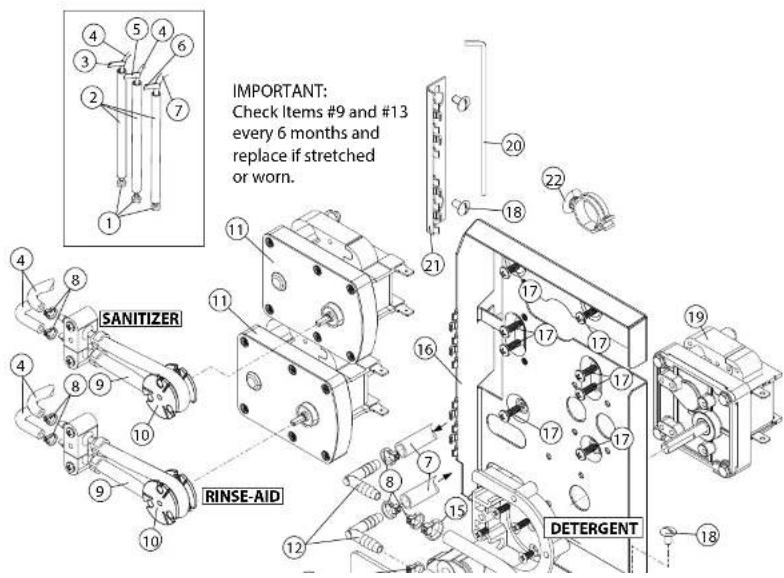
UL130 - Chemical Dispensing Pumps
| Item No. | Part No. | Description | Qty. | |
| 1 | 0501869 | STRAINER | 2 | |
| 2 | 0306363 | TUBE, 3/8" ID X 12" LG. STIFFENER 1 | ||
| 3 | 0505483 | LABEL, RINSE-AID HOSE 1 | ||
| 4 | 0502666 | HOSE, 1/8" ID X 1/4" OD PVC A/R | ||
| 5 | 0503694 | LABEL, SANITIZER HOSE A/R | ||
| 6 | 0503695 | LABEL, DETERGENT HOSE A/R | ||
| 7 | 0502667 | HOSE, 1/4" ID X 3/8" OD PVC A/R | ||
| 8 | 0501519 | TIE, NYLON 4" 7 | ||
| 9 | 0706635 | TUBE, ELEMENT ASSEMBLY 45CC 1 | ||
| 10 | 0707142 | ROTOR | 1 | |
| 11 | 0503756 | MOTOR, INJECTOR PUMP | 1 | |
| 12 | 0502644 | ELBOW, 1/4" HOSE BARB | 2 | |
| 13 | 114202 | TUBE, 3/16" ID X 3/8" OD X 9" LG. | 1 | |
| 14 | 114203 | PUMP HD KIT, PERISTALIC 1 | ||
| 15 | 0512369 | CLAMP, HOSE | 1 | |
| 16 | 0313393 | BRACKET, CHEMICAL PUMP | 1 | |
| 17 | 0504822 | SCREW, 8-32 X 1/2" PAN HD. SST | 4 | |
Booster Assembly - UH130B, UH230B
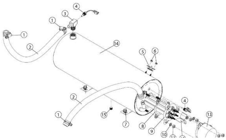
UH130B, UH230B - Booster Assembly
| Item No. | Part No. | Description | Qty. |
| 1 | 0512985 | CLAMP, SS GEAR-MIN. 1/2" 4 | |
| 2 | 107417 | HOSE, RUBBER 1/2" ID X .84" OD A/R | |
| 3 | 0513314 | TEE, RINSE 1 | |
| 4 | 0513310 THERMISTOR 10 kΩ, 2-WIRE 2 | ||
| 5 | 110562 | THERMOSTAT, HIGH LIMIT 240°F 1 | |
| 6 | 108954 | NUT, GRIP 6-32 W/NYLON INSERT SST 2 | |
| 7 | 0512185 | BOLT, HEX FLANGE, 1/4-20 X 3/8" SST 2 | |
| 8 | 109985 | SEAL, BOOSTER ELEMENT | 1 |
| 9 | 111235-1 | BOOSTER, ELEMENT 5 KW, 40°F RISE 1 | |
| - | 111233 | BOOSTER, ELEMENT 9 KW, 70°F RISE | 1 |
| 10 | 106482 | WASHER, LOCK 1/4" SPLIT SST 3 | |
| 11 | 100003 | NUT, PLAIN 1/4-20 SST 6 | |
| 12 | 111885 | INSULATOR 1 | |
| 13 | 107908 | COVER, ELEMENT 1 | |
| 14 | 0713333 TANK, BOOSTER SST | 1 | |
| 15 | 0508817 PLUG, 1/8" | 1 |
Power Input Block and Cord Assemblies - All Models

All Models - Power Input Block and Cord Assemblies
| Item No. | Part No. | Description | Qty. | |
| 1 | 0313396 | COVER, BOX WIRING 1 | ||
| 2 | 0501411 | SCREW, 10-32 X 1/4", TRUSS HD. 2 | ||
| 3 | 0512432 | CONTACTOR, 3-POLE 120VAC COIL 1 | ||
| 4 | 0509527 | BLOCK, TERMINAL, 4-POLE 1(All except UL130) | ||
| 5 | 103310 | LUG, GROUND 1 | ||
| 6 | 0313395 | BOX, WIRING 1 | ||
| 7 | 107964 | BUSHING, STRAIN RELIEF, SMALL A/R | ||
| 8 | 201029-1 | NUT, LOCK 1/2 INCH NI PLATED | A/R | |
| 9 | 0512099 | O-RING | 1 | |
| 10 | 0513312 | CORD AND PLUG, 115VAC(UL130 Only) | 1 | |
| 11 | 0507323 | THERMOSTAT, WASH (UL130 Only) | 1 | |
| 12 | 0503647 | RELIEF, STRAIN | 1 | |
| 13 | 0501450 | SCREW, 6-32 X 3/16" NIBS, RH PHIL. SST | 2 | |
| 14 | 0313410 | BRACKET, POWER CORD | 1 | |
| 15 | 0512185 | BOLT, HEX FLANGE, 1/4-20 X 3/8" SST | 1 | |
| 16 | 0503592 | LABEL, GROUND | 1 |
Timer Control Board Assembly - UH130B, UH230B, UH330B

UH130B, UH230B, UH330B - Timer Control Board Assembly
| Item No. | Part No. | Description | Qty. |
| 1 | 0313397 | BOX, CONTROL BOARD (ALL EXCEPT UH330B) 1 | |
| - | 0313397-1 | BOX, CONTROL BOARD (UH330B ONLY) 1 | |
| 2 | 0712105 | TIMER CKT. BD. (ALL EXCEPT UH330B) 1 | |
| - | 0513575 | TIMER CKT. BD. (UH330B ONLY) 1 | |
| 3 | 0501464 | SCREW, 10-24 X 3/8; TRUSS HD. SST 2 | |
| 4 | 0512373 | FUSE, 4A 250V (ALL EXCEPT UH330B) 1 | |
| - | 0513698 | FUSE, 6A 250V (UH330B ONLY) 1 | |
| 5 | 0313398 | COVER, BOX (ALL EXCEPT UH330B) 1 | |
| - | 0313398-1 | COVER, BOX (UH330B ONLY) 1 | |
| 6 | 0501411 | SCREW, 10-32 X 1/4" SST | 1 |
| 7 | 0501373 | SWITCH, BOOSTER FILL | 1 |
| 8 | 0512973 | STANDOFF | |
| 9 | 107964 | BUSHING, STRAIN RELIEF | |
| 10 | 0512781 HOLDER, FUSE | 1 | |
| 11 | 0313644 PIN, HINGE | 1 | |
| 12 | 0501408 SCREW, 8-32 X 1/4" TRUSS HD. PHIL. SST | 6 | |
| 13 | 0313431 BRACKET, HINGED PANELS | 1 |
Wash and Rinse Spray Arms and Drain Valve - UH230, UH230B, UH330B
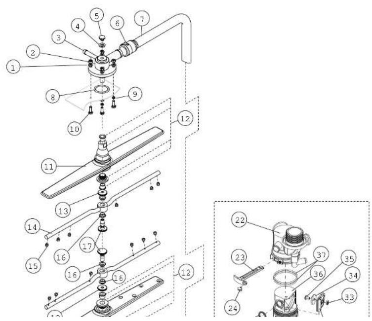
UH230, UH230B, UH330B - Wash and Rinse Spray Arms and Drain Valve
| Item No. | Part No. | Description | Qty. |
| 1 | 0501478 | WASHER, 17/64 id X 9/16" OD SST 4 | |
| 2 | 107967 | NUT, HEX 1/40-20 NYLON INSERT SST 4 | |
| 3 | H35509 | HUB, UPPER SPRAY ARMS 1 | |
| 4 | 107873 | WASHER, PACKING 1 | |
| 5 | 110215 | PLUG, UPPER MANIFOLD 1 | |
| 6 | 0502571 | CLAMP, HOSE GEAR 1-1/2" SST 2 | |
| 7 | 0512120 | HOSE, UPPER WASH ARM 1 | |
| 8 | 0512133 | O-RING, 2-1/8" OD X 1-3/4" ID X 3/16" 1 | |
| 9 | 0501481 | WASHER, NYLITE | 4 |
| 10 | 100738 | BOLT, 1/4-20 X 1" SST | 4 |
| 11 | H420548 | WASH ARM ASSEMBLY (Includes Item 12) | 2 |
| 12* | 0712749 BEARING ASSEMBLY | 2 | |
| 13 | H34998 | NUT, SPACER | 2 |
| 14 | H36211 | RINSE ARM ASSEMBLY (Includes Items 13, 16, and 17) | 2 |
| 15 | H37149 | NOZZLE, RINSE ARM | 12 |
| 16 | H190663 | BEARING, RINSE ARM | 4 |
| 17 | H36275 | SPINDLE, RINSE ARM | 2 |
| 18 | 0512124 | SHAFT, LOWER | 1 |
| 19 | 0512239 O-RING | ||
| 20 | 0512066 | HUB, LOWER WASH ARM | 1 |
| 21 | 0512133 | O-RING, 2-1/8" OD X 1-3/4" ID X 3/16" | 1 |
| 22 | 0513439 | HOUSING, MANIFOLD FWR | 1 |
| 23 | 0513443 | PIN, RETENTION | 1 |
| 24 | 0509439 | SCREW, RETENTION PIN 10-32 X 5/16" SST | 1 |
| 25 | 0513446 | O-RING, QUAD | 1 |
| 26 | 0513445 | O-RING, PIVOT SHAFT | 2 |
| 27 | 0513447 | SHAFT, FLAPPER | 1 |
| 28 | 0712123 | MOTOR, DRAIN VALVE | 1 |
| — | 0509257 PIN MOTOR (COMES WITH MOTOR) | 1 |
Wash/Rinse Spray Arm and Drain Valve - UH130, UH130B, UL130

UH130, UH130B, UL130 - Wash/Rinse Spray Arm and Drain Valve
| Item No. | Part No. | Description | Qty. |
| 1 | 0501478 | WASHER, 17/64" ID X 9/16" OD SST 4 | |
| 2 | 107967 | NUT, HEX SST 1/4-20 NYLON INSERT 4 | |
| 3 | H35509-1 | HUB, UPPER WASH ARM 1 | |
| 4 | 107873 | WASHER, PACKING 1 | |
| 5 | 110215 | SCREW, RETAINING 1 | |
| 6 | 0502571 | CLAMP, HOSE GEAR HOSE 1-1/2" SST 2 | |
| 7 | 0512120 | HOSE, UPPER WASH ARM 1 | |
| 8 | 0512133 | O-RING, 2-1/8" OD X 1-3/4" ID X 3/16 | 1 |
| 9 | 100738 | BOLT, 1/4-20 X 1" HEX. HD. SST | 4 |
| 10 | 0501481 WASHER, NYLTITE | 4 | |
| 11 | H420548 WASH ARM ASSEMBLY (Includes Item 12) | ||
| 12* | 0712749 BEARING ASSEMBLY | 2 | |
| 13 | 0512129 NUT, WASH ARM | 2 | |
| 14 | 0512125 SHAFT, LOWER | 1 | |
| 15 | 0512066 HUB, LOWER WASH ARM | 1 | |
| 16 | 0512133 O-RING, 2-1/8" OD X 1-3/4" ID X 3/16 | 1 | |
| 17 | 0513440 HOUSING, MANIFOLD | 1 | |
| 18 | 0513443 PIN, RETENTION | 1 | |
| 19 | 0509439 SCREW, RETENTION PIN 10-32 X 5/16" SST | 1 | |
| 20 | 0513446 O-RING, QUAD | 1 | |
| 21 | 0513445 O-RING, PIVOT SHAFT | 2 | |
| 22 | 0513447 SHAFT, FLAPPER | 1 |
Control Panel - UH130, UH130B

UH130, UH130B - Control Panel
| Item No. | Part No. | Description | Qty. |
| 1 | 0512221 | SWITCH, ROCKER DPST 250V NEON 1 | |
| 2 | 0512213 | SWITCH, PIEZIO 2 | |
| 3 | 0512232 | LIGHT, INDICATOR, GREEN 2 | |
| 4 | 0512226 | SWITCH, ROCKER RND SPDT MOMENTARY 1 | |
| 5 | 0501408 | SCREW, TRUSS PHIL. SST 8-32 X 1/4" 2 | |
| 6 | 0513540 | LABEL, FACIA 1 | |
| 7 | 0313418 | PANEL, FACIA 1 | |
| 8 | 0512357 | STANDOFF, LED DISPLAY BOARD 2 | |
| 9 | 0503580 | NUT, 10-32 2 | |
| 10 | 0501563 SCREW, #8 X 3/8" | 4 | |
| 11 | 0512106-1 | TEMPERATURE INDICATOR BD., DIGITAL | |
| – | 0512362 | HARNESS, DIGITAL DISPLAY WIRING (Not Shown) | 1 |
| – | 0513537 | HARNESS, COMPLETE MACHINE (Not Shown)) |
Control Panel - UH230, UH230B
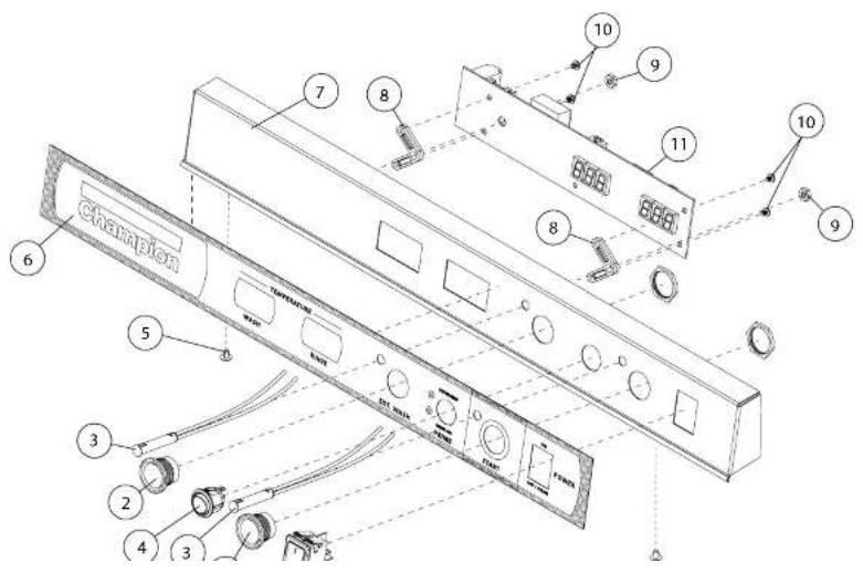
UH230, UH230B - Control Panel
| Item No. | Part No. | Description | Qty. |
| 1 | 0512221 | SWITCH, ROCKER DPST 250V NEON 1 | |
| 2 | 0512213 | SWITCH, PIEZIO 2 | |
| 3 | 0512232 | LIGHT, INDICATOR, GREEN 2 | |
| 4 | 0512226 | SWITCH, ROCKER RND SPDT MOMENTARY 1 | |
| 5 | 0501408 | SCREW, TRUSS PHIL. SST 8-32 X 1/4" 2 | |
| 6 | 0513539 | LABEL, FACIA 1 | |
| 7 | 0313417 | PANEL, FACIA 1 | |
| 8 | 0512357 | STANDOFF, LED DISPLAY BOARD 2 | |
| 9 | 0503580 | NUT, 10-32 2 | |
| 10 | 0501563 SCREW, #8 X 3/8" | 4 | |
| 11 | 0512106-1 TEMPERATURE INDICATOR BD., DIGITAL | ||
| - | 0512362 | HARNESS, DIGITAL DISPLAY WIRING (Not Shown) | 1 |
| - | 0513536 HARNESS, COMPLETE MACHINE (Not Shown)) |
Control Panel - UH330B
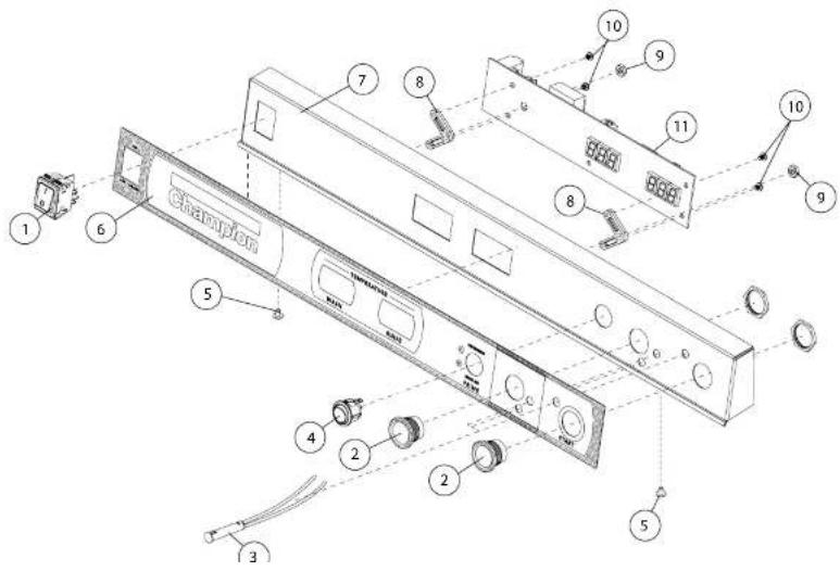
UH330B - Control Panel
| Item No. | Part No. | Description | Qty. |
| 1 | 0512221 | SWITCH, ROCKER DPST 250V NEON 1 | |
| 2 | 0512213 | SWITCH, PIEZIO 2 | |
| 3 | 0512232 | LIGHT, INDICATOR, GREEN 3 | |
| 4 | 0512226 | SWITCH, ROCKER RND SPDT MOMENTARY 1 | |
| 5 | 0501408 | SCREW, TRUSS PHIL. SST 8-32 X 1/4" 2 | |
| 6 | 0513579 | LABEL, FACIA 1 | |
| 7 | 0713583 | PANEL, FACIA 1 | |
| 8 | 0512357 | STANDOFF, LED DISPLAY BOARD 2 | |
| 9 | 0503580 | NUT, 10-32 2 | |
| 10 | 0501563 SCREW, #8 X 3/8" | 4 | |
| 11 | 0512106-1 TEMPERATURE INDICATOR BD., DIGITAL | ||
| – | 0512362 | HARNESS, DIGITAL DISPLAY WIRING (Not Shown) | 1 |
| – | 0513536 HARNESS, COMPLETE MACHINE (Not Shown)) |
Control Panel - UL130

UL130 - Control Panel
| Item No. | Part No. | Description | Qty. |
| 1 | 0512220 | SWITCH, ROCKER DPST 125V NEON 1 | |
| 2 | 0512214 | SWITCH, PUSH-BUTTON, GREEN 1 | |
| 3 | 0512232 | LIGHT, INDICATOR, GREEN 2 | |
| 4 | 0512226 | SWITCH, ROCKER RND SPDT MOMENTARY 2 | |
| 5 | 0512320 | GASKET, STEAM 1 | |
| 6 | 0512107 | THERMOMETER, 2" DIAL, 7" CAPILLARY 1 | |
| 7 | 0501408 | SCREW, TRUSS PHIL. SST 8-32 X 1/4" 2 | |
| 8 | 0513503 | LABEL, FACIA 1 | |
| 9 | 0313419 | PANEL, FACIA 1 | |
| 10 | 0512215 SWITCH, PUSH BUTTON, WHITE | 1 |
Panels- UH130, UH130B, UH230, UH230B, UL130

| Item No. | Part No. | Description | Qty. |
1 0313406 PANEL, FRONT WITHOUT GAUGE HOLE 1
2 0313407 PANEL, FRONT WITH GAUGE HOLE 1
3 0513735 GASKET 1
4 109812 GAUGE, PRESSURE 0-60 PSI 1
5 100779 SCREW 1/4-20 X 5/8" TRUSS SS PHIL A/R
6 0513659 FITTING, 1/4" TUBE X 1/8" FNPT PP 1
7 107928 TUBING, 1/4" NATURAL A/R
8 0313403 PANEL, LH SIDE 1
9 0503718 FOOT, ADJUSTING 4
10 0313402 PANEL, RH SIDE 1
11 0313401 PANEL, TOP 1
12 0313404 PANEL, REAR 1
13 100007 SCREW, TRUSS SLOT SST 10-32 X 3/8" A/R
Panels - UH330B

UH330B - Panels
| Item No. | Part No. | Description | Qty. |
1 0313406 PANEL, FRONT 1
2 100779 SCREW 1/4-20 X 5/8" TRUSS SS PHIL A/R
3 0513735 GASKET 1
4 0313403 PANEL, LH SIDE 1
5 0503718 FOOT, ADJUSTING 4
6 0313402 PANEL, RH SIDE 1
7 0313584 PANEL, TOP 1
8 100007 SCREW, TRUSS SLOT SST 10-32 X 3/8" A/R
9 0313431 PANEL, REAR 1
Door Assembly - All Models
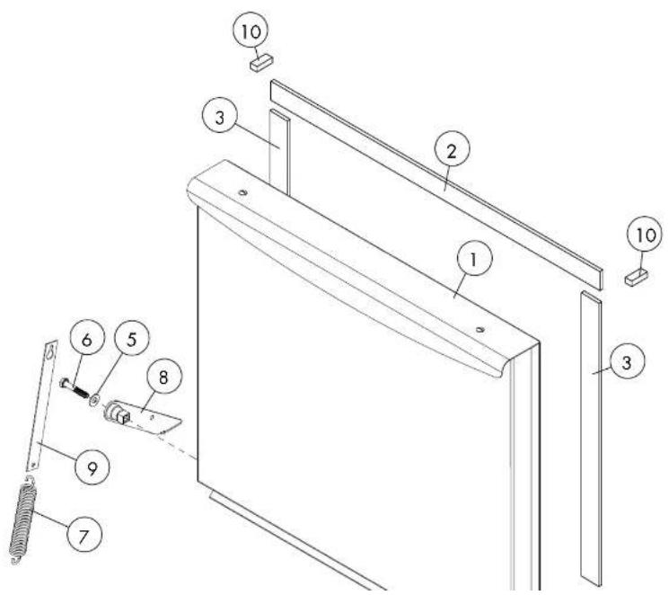
All Models - Door Assembly
| Item No. | Part No. | Description | Qty. |
1 0713136 DOOR ASSEMBLY 1
2 0513558 GASKET, DOOR TOP 1
3 0513727 GASKET, DOOR SIDE 2
4 0713428 HINGE, RH ASSY 1
5 0501476 WASHER, 9/32" X 5/8" OD SS 1
6 0501422 BOLT, HEX SS 1/4-20 X 1-1/2" 1
7 0513332 SPRING, DOOR 2
8 0713429 HINGE, LH ASSY 1
9 0313430 ARM, DOOR SPRING 2
10 0512320 GASKET, STEAM (UL130 ONLY) 2
Dish Racks, Line Strainer, PRV

[NO TEXT]
Dish Racks, Line Strainer, PRV
Item No.
Part No.
Description
Qty.
1 101273 DISH RACK, FLAT-BOTTOM AR
2 101285 DISH RACK, PEG AR
3 104421 STRAINER, LINE 1/2" BRONZE 1 (UH230, UH230B)
4 108265 VALVE, PRESSURE REGULATING (PRV) 1 (UH230, UH230B)
Blank Page
This Page Intentionally Left Blank
Electrical Schematics
Electrical Schematics and Timing Charts
Illustrations Page
Electrical Schematic - Low Temperature Model - UL130 114
Electrical Schematic - High Temperature Models - UH130, UH130B, UH230, UH230B ..... 115
Electrical Schematic - High Temperature Heat Recovery Model - UH330B....116
Timing Charts - UH130, UH130B, UH230, UH230B, UL130 117
Timing Chart 11H320R 118
Electrical Schematic - UL130

Electrical Schematic - UH130, UH130B, UH230, UH230B

Electrical Schematic - UH330B

| MINIMUM | MAXIMUM | ||
| 1 | FILL. VALVE | 20 SEC. | 55 SEC |
| 2 | DET. PUMP | 0 SEC. | 12 SEC. |
| 3 | SAN. PUMP | 0 SEC. | 20 SEC. |
| 4 | RINSE AID PUMP | 0 SEC. | 10 SEC. |
ARROW INDICATES THAT FUNCTION END TIME IS VARIABLE WITH THE ADJUSTMENT POTENTIOMETER
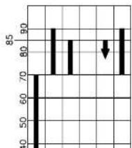
WASHING TIME AT 70 SECS 1.5 TO 70 SEC

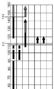
AND DUMP DENOTES ADJUSTABLE TIME 5 MINUTES EXTRA WASHING TIME AT 90 SECS ANY TIME FROM 0.5 TO 90 SEC
Timing Chart - UH330B
UH330B Timing Charts
TIMING CHART FOR FRESH WATER RINSE HEAT RECOVERY

NORMAL - WASH=70 TOTAL CYCLE=150 MEDIUM - WASH=120 TOTAL CYCLE=200 LONG - WASH=195 TOTAL CYCLE=277
| MINIMUM | MAXIMUM | ||
| 1 | TILL VALVE | 2 SCD. | 60 SCD |
| 2 | DET. PUMP | 0 SCD. | 12 SCD. |
| 4 | RINSE AID PUMP | 0 SCD. | 5 SCD. |
ARROW INDICATES THAT FUNCTION END THE IS VARIABLE WITH THE ADJUSTMENT POTENTOMETER
UH330B SETTING
1 3 SELECTABLE WASH TIMES 70/120/198
2 S/L CL FLASHES WHEN CYCLE IS SELECTED - TURNS SOLID WHEN CYCLE START IS PUSHED - CYCLE LIGHT STAYS ON UNTIL END OF CYCLE.
3 FILL MAY HAPPEN AS REQUIRED BY WATER LEVEL SENSOR ANY TIME WHEN MACHINE IS
NOT IS CYCLE. DURING CYCLE FILL MAY NOT OCCUR DURING LOCKOUT PERIOD DENOTED BY
601HR SETTING
1 EXTENDED MASH ADDS 15 MINUTES EXTRA WASHING TIME AT 70 SECS SWITCH MAY BE PUSHED ANY TIME FROM 0.5 TO 70 SEC
(SAME FEATURE AS STANDARD 0512105 CONTROL)
2 C/L ON BEGINNING TO END OF CYCLE. E/W LIGHT ON WHEN BITN, PUSHED TO END OF CYCLE OR WHEN CANOLED BY PUSHING AGAIN.
(SAME FEATURE AS STANDARD 0512105 CONTROL)
3 SAME AS (3) ABOVE.

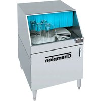

- UNDERCOUNTER DISHWASHERS M4 SERIES
- NATIONAL SERVICE DEPARTMENT
- ATTENTION
- REGISTER YOUR PRODUCT ONLINE
- PRODUCT REGISTRATION BY FAX
- REVISION HISTORY
- LIMITED WARRANTY
- TABLE OF CONTENTS
- TABLE OF CONTENTS (CONTINUED)
- MODEL UH330B
- MODEL DESCRIPTIONS
- UH130B
- WASH REFRESH PUMPED FINAL RINSE
- UH230B
- FRESH WATER FINAL RINSE
- UH130
- WASH REFRESH FINAL RINSE
- UH230
- UL130
- CHEMICAL SANITIZING WASH REFRESH FINAL RINSE
- NOTE
- CAUTION
- ELECTRICAL CONNECTIONS - UH130, UH230 1PH WITHOUT BUILT-IN BOOSTER
- WARNING
- SINGLE PHASE POWER REQUIREMENT
- CONNECTING INCOMING POWER TO THE MAIN TERMINAL BLOCK FOR 1PH AND 3PH MACHINES WITH BOOSTERS-UH130B, UH230B
- CONNECTING INCOMING POWER TO THE MAIN TERMINAL BLOCK FOR 1PH AND 3PH MACHINES WITH BOOSTERS
- VERY IMPORTANT! THE BOOSTER HEATER IS WIRED FOR 1PH OPERATION WHEN SHIPPED. FOLLOW THE INSTRUCTIONS BELOW TO WIRE THE BOOSTER FOR 3PH
- VERY IMPORTANT
- ATTENTION! CHANGE THE DATA PLATE ON THE LOWER FRONT PANEL OF THE MACHINE AFTER THE MACHINE IS WIRED FOR 3PH AND THE BOOSTER HEATER IS CONNECTED FOR 3PH
- FOR A DIRECT DRAIN CONNECTION
- FOR AN INDIRECT DRAIN CONNECTION
- BOOSTER FILL SWITCH - (FILLING THE BOOSTER TANK FOR THE FIRST TIME)
- UH130B AND UH230B ONLY
- CHEMICAL DISPENSING PUMPS
- INJECTION POINT LOCATIONS
- DETERGENT AND RINSE-AID DISPENSING PUMPS - PUMP AND FILL ADJUSTMENTS UH130, UH130B AND UH230, UH230B
- VERY IMPORTANT! DO NOT OVERLOAD THE DISH RACK. LOAD ONE DISH RACK INTO THE MACHINE AT A TIME
- PLACE AN EMPTY DISHRACK IN THE MACHINE AND RUN THE FIRST CYCLE EMPTY TO HEAT THE WASH TANK INTERIOR
- DOOR LEFT OPEN DURING WASH CYCLE
- RINSE SENTRY MODE WILL EXTEND WASH CYCLE TIME
- EXTENDED WASH MODE
- MODEL UH230, UH230B ONLY
- DRAIN MODE
- DRAINING PROBLEMS RELATED TO IMPROPER INSTALLATION
- DRAIN AND CLEAN THE DISHWASHER EVERY 2 HOURS OF CONTINUOUS OPERATION, AFTER EACH MEAL PERIOD, AND AT THE END OF THE DAY
- ALL MODELS
- CLEANING THE WASH TANK
- UH230, UH230B RINSE ARMS
- SCRAP SCREEN AND SUMP STRAINER
- DE-LIMING CAUTIONS AND WARNINGS
- DANGER
- UH130 AND UH130B DE-LIMING PROCEDURE
- READ AND FOLLOW THE DE-LIMING CAUTIONS AND WARNINGS ON PAGE 32 BEFORE DE-LIMING THE MACHINE
- UH230 AND UH230B DE-LIMING PROCEDURE
- FOLLOW THE PROCEDURES BELOW TO DE-LIME THE UH230, UH230B DISHWASHER
- UH130, UH130B AND UH230, UH230B - MAINTENANCE
- DAILY MAINTENANCE
- WEEKLY MAINTENANCE
- MONTHLY MAINTENANCE
- DRAIN CONNECTION - UL130
- VERY IMPORTANT! IMPROPER INSTALLATION OF MACHINE DRAIN HOSE
- PUMP AND TANK FILL ADJUSTMENTS
- RUN THE FIRST CYCLE WITH AN EMPTY DISH RACK TO HEAT THE WASH TANK INTERIOR
- EXTENDED WASH MODE - MODEL UL130
- VERY IMPORTANT! DRAIN AND CLEAN THE DISHWASHER EVERY 2 HOURS OF CONTINUOUS OPERATION, AFTER EACH MEAL PERIOD, AND AT THE END OF THE DAY
- DE-LIME MODE - MODEL UL130
- MODEL UL130 DE-LIMING
- MAINTENANCE - MODEL UL130
- TROUBLESHOOTING
- ILLUSTRATIONS
- DIGITAL TEMPERATURE DISPLAY CODES
- BOOSTER DISPLAY CODES
- DIAGNOSTIC TESTING FOR THE SOLID STATE TIMER BOARD, P/N 0712105
- 1
- 2
- 3
- 4
- 5
- BOOSTER HEATER/WASH TANK HEATER INTERLOCK CIRCUIT OPERATION
- INTERLOCK CIRCUIT OPERATION
- SINGLE PHASE UH330B
- CONNECTING INCOMING POWER TO THE MAIN TERMINAL BLOCK FOR 1PH AND 3PH MACHINES WITH BOOSTERS - UH330B
- UH330B - CONNECTING INCOMING POWER TO THE MAIN TERMINAL BLOCK FOR 1PH AND 3PH
- BOOSTER HEATER CONVERSION FROM 1PH TO 3PH OPERATION
- COMPLETING THE 1PH TO 3PH ELECTRICAL CONVERSION
- ATTENTION! CHANGE THE DATA PLATE ON THE LOWER FRONT PANEL OF THE MACHINE
- AFTER THE MACHINE IS WIRED FOR 3PH AND THE BOOSTER HEATER IS CONNECTED FOR 3PH
- ATTENTION! THE MODEL UH330B REQUIRES A SINGLE 1/2" INCOMING COLD WATER SUPPLY LINE
- IMPORTANT
- CHEMICAL CONNECTIONS - MODEL UH330B
- CHEMICAL INJECTION POINTS
- PRIMING THE DISPENSING PUMPS
- CHEMICAL DISPENSING PUMP ADJUSTMENTS
- ATTENTION! THE FILL AND SANITIZER ADJUSTMENT SCREWS ARE NOT USED ON THE UH330B MACHINE
- OPERATION - MODEL UH330B
- UH330B CONTROL PANEL
- WASH MODE
- RINSE ARMS
- FOLLOW THE PROCEDURES BELOW TO DE-LIME THE UH330B DISHWASHER
- MODEL UH330B - MAINTENANCE
- REFER TO PAGES 55-63 FOR ADDITIONAL TROUBLESHOOTING INFORMATION
- SERVICE REPLACEMENT PARTS
- PAGE
- ELECTRICAL SCHEMATICS AND TIMING CHARTS
- UH330B SETTING
- 601HR SETTING
Brand : Champion
Model : UH330B M4
Category : Dishwasher