
DTP T DWP 4K 232 D - Wall socket Extron - Free user manual and instructions
Find the device manual for free DTP T DWP 4K 232 D Extron in PDF.


| Product Type | Wall plate transmitter for HDMI and DisplayPort over twisted pair |
| Model | DTP T DWP 4K 232 D |
| Brand | Extron |
| Inputs | 1 HDMI, 1 DisplayPort; 1 analog audio (3.5 mm stereo jack) |
| Output | 1 DTP twisted pair (RJ-45) |
| Control Ports | RS-232 (3-pole captive screw) for SIS; Over TP RS-232/IR (5-pole) |
| Power Supply | External 12 VDC, 100-240 VAC input; included; single supply powers both transmitter and receiver |
| Maximum Transmission Distance | 230 ft (70 m) for 720p/1080p over STP cable |
| Supported Cable | Shielded twisted pair (STP) only; use Extron XTP DTP 24 SF/UTP recommended |
| HDCP Support | Yes, full DDC and HDCP transmission |
| Audio Embedding | Analog audio can be embedded onto digital video; selectable modes |
| Mounting | Two-gang electrical wall box or mud ring; decorator-style faceplate included |
| Dimensions (approx.) | Fits standard 2-gang wall box; depth requires min 3.0 in (7.6 cm) |
| Weight | Approximately 0.5 lb (0.23 kg) |
| Warranty | 3 years from date of purchase |
| Regulatory Compliance | FCC Class A, CE; requires STP cable for compliance |
| Operating Temperature | Standard commercial environment (not specified, assume 0-40°C) |
| Remote Control | via RS-232 using Simple Instruction Set (SIS) commands |
| EDID Management | 22 factory EDID files plus 2 user slots; selectable per input |
| LED Indicators | Power (amber/green), Auto Switch, HDCP |
Frequently Asked Questions - DTP T DWP 4K 232 D Extron
User questions about DTP T DWP 4K 232 D Extron
0 question about this device. Answer the ones you know or ask your own.
Ask a new question about this device
Download the instructions for your Wall socket in PDF format for free! Find your manual DTP T DWP 4K 232 D - Extron and take your electronic device back in hand. On this page are published all the documents necessary for the use of your device. DTP T DWP 4K 232 D by Extron.
USER MANUAL DTP T DWP 4K 232 D Extron
DTP T DWP 4K D Series
HDMI and DisplayPort
Twisted Pair Extender Transmitters
Safety Instructions
Safety Instructions • English
WARNING: This symbol, when used on the product, is intended to alert the user of the presence of uninsulated dangerous voltage within the product's enclosure that may present a risk of electric shock.
ATTENTION: This symbol. When used on the product, is intended to alert the user of important operating and maintenance (servicing) instructions in the literature provided with the equipment.
For information on safety guidelines, regulatory compliances, EMI/EMF compatibility, accessibility, and related topics, see the Extron Safety and Regulatory Compliance Guide, part number 68-290-01, on the Extron website, www.extron.com.
This equipment has been tested and found to comply with the limits for a Class A digital device, pursuant to part 15 of the FCC rules. The Class A limits provide reasonable protection against harmful interference when the equipment is operated in a commercial environment. This equipment generates, uses, and can radiate radio frequency energy and, if not installed and used in accordance with the instruction manual, may cause harmful interference to radio communications. Operation of this equipment in a residential area is likely to cause interference. This interference must be corrected at the expense of the user.
ATTENTION: The Twisted Pair Extension technology works with shielded twisted pair (STP) cables only. To ensure FCC Class A and CE compliance, STP cables and STP connectors are also required.
For more information on safety guidelines, regulatory compliances, EMI/EMF compatibility, accessibility, and related topics, see the "Extron Safety and Regulatory Compliance Guide" on the Extron website.
Conventions Used in this Guide
Notifications
The following notifications are used in this guide:
CAUTION: Risk of minor personal injury.
NOTE: A note draws attention to important information.
Software Commands
Commands are written in the fonts shown here:
^AR Merge Scene,,Op1 scene 1,1 ^B51 ^W^C
[01] R000400300004000080000600 [02] 35 [17] [03]

NOTE: For commands and examples of computer or device responses mentioned in this guide, the character "0" is used for the number zero and "0" is the capital letter "o."
Computer responses and directory paths that do not have variables are written in the font shown here:
Reply from 208.132.180.48: bytes=32 times=2ms TTL=32
C:\Program Files\Extron
Variables are written in slanted form as shown here:
ping xxx.xxx.xxx.xxx -t
SOH R Data STX Command ETB ETX
Selectable items, such as menu names, menu options, buttons, tabs, and field names are
Contents
Introduction....1
About this Guide....1
About the DTP T DWP 4K D Series .... 1
Twisted Pair Cable Advantages....2
Transmission Distance 2
Features 2
Installation and Operation....3
Mounting the Transmitter 3
UL and Safety Guidelines....3
Site Preparation and Wall Box Installation ..... 4
Mud Ring Installation 5
Final Installation 6
DTP T DWP 4K D Series
Connections....6
Front Panel 6
Rear Panel....7
Twisted Pair Recommendations for DTP
Communication 8
Supported Cables 8
Cable Recommendations 8
Remote Control....14
Simple Instruction Set Control 14
Host-to-Extender Communications....14
Transmitter-Initiated Messages....14
Error Responses....15
Timeout 15
EDID 15
TMDS Output Format 15
DTP T DWP 4K D EDID Memory Locations... 16
Using the Command and Response Table.... 17
Command and Response Table for SIS
Commands 19
Reference Information 23
Decorator-Style Wallplate Template
Dimensions 23
Introduction
- About this Guide
• About the DTP T DWP 4K D Series Extenders - Features
About this Guide
This guide provides instructions for experienced, professional installers to install, operate, and configure the Extron DTP T DWP 4K D series of High-Definition Multimedia Interface (HDMI®) and DisplayPort® Extenders.
Terms Used in this Guide
The terms "extender" and "transmitter" are used interchangeably in this guide to refer to all of the DTP T DWP 4K D models.
About the DTP T DWP 4K D Series Extenders
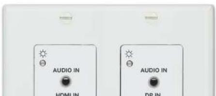
The Extron DTP T DWP 4K D extenders are a series of HDMI and DisplayPort transmitters (see figure 1) that are housed in enclosures that can be mounted in Underwriters Laboratories (UL) standard wall boxes with decorator-style faceplates. Paired with a compatible DTP 230 or 330 receiver, they extend the usable distance of HDMI digital video, DisplayPort digital video, and RS-232 or IR control signals over one shielded twisted pair (S1P) cable. The extenders also route and embed audio.
DTP T DWP 4K D systems consist of a transmitter (Tx) and a receiver (Rx). The transmitters and corresponding compatible receivers are sold separately. Each purchased transmitter is shipped with a single external desktop 12 VDC power supply that accepts 100 to 240 VAC, 50-60 Hz input. A single power supply connected to either the transmitter or a compatible receiver can power both units through the twisted pair cable that links the units.
Twisted Pair Cable Advantages
Twisted pair cable is much smaller, lighter, more flexible, and less expensive than coaxial, HDMI, or DisplayPort cable. These transmitter and receiver twisted pair (TP) products make cable runs simpler and less cumbersome. Termination of the cable with RJ-45 connectors is simple, quick, and economical (see Twisted Pair Recommendations for DTP Communication on page 8 for more information).
NOTE: Do not use Extron UTP23SF-4 Enhanced Skew-Free AV UTP cable or STP201 cable to link the transmitter and receiver. The DTP T DWP 4K 232 D and 332 D do not work properly with these cables.
Transmission Distance
The maximum transmission distance is determined by the resolution of the signal and the twisted pair cable, graphics card, and display used in the system.
- DTP T DWP 4K 232 D Transmitters can transmit 720p, 1080i or 1080p HDTV video signals up to 230 feet (70 meters) over STP cable.
- DTP T DWP 4K 332 D transmitters can transmit 720p, 1080i or 1080p HDTV video signals up to 330 feet (100 meters) over STP cable.
Features
Transmits HDMI and DisplayPort signals over one STP cable — Twisted pair cables provide an economical, easily installed cable solution.
Supports DDC and HDCP transmission — The transmitters fully support long distance transmission of the DDC and HDCP signals.
Installation and Operation
This section describes the installation and the operation of the extenders, including:
• Mounting the Transmitter
• DTP T DWP 4K D Series Connections
• Twisted Pair Recommendations for DTP Communication
• Power Supply Wiring
• RS-232 and IR Connector Wiring
- Operation
Mounting the Transmitter
ATTENTION:
The transmitters can be installed in a two-gang electrical wall box, or with a mud ring with a
Site Preparation and Wall Box Installation
Choose a location that allows cable runs without interference. Allow enough depth for both the wall box and the cables. Install the cables into the wall, furniture, or conduits before installing the wallplate.
NOTE: The extender units are very deep and have connectors on the back side. Extron recommends a 2-gang wall box which has a depth of at least 3.0 inches (7.6 cm) to accommodate the connectors and cables.
To install a new wall box, perform steps 1 through 9. If a suitable wall box is already installed, perform steps 6 through 9 on the next page. UL Listed wall boxes are recommended.
- If a wall box is not available to use for a template, use the dimensions on the Decorator-Style Wallplate Template Dimensions on page 23 to create a template. If installing directly into furniture, cut out the center portion of the template. To download a printable template, go to www.extron.com.
- Place the wall box (or the full size template) against the installation surface, and mark the opening guidelines.
- Cut out the material from the marked area.
- Insert the wall box into the opening. The rear connectors on the box or wallplate should fit easily into the opening. Enlarge or smooth the edges of the opening if needed.
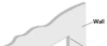
- Secure the wall box with nails or screws, leaving the front edge flush with the outer wall or furniture surface (see figure 2).
NOTES:
- If attaching the wall box to wood, use four #8 or #10 screws or 10-penny nails. A minimum of 0.5 inch (1.3 cm) of screw thread must penetrate the wood.
- If attaching the wall box to metal studs or furniture, use four #8 or #10 self-tapping sheet metal screws or machine bolts with matching nuts.

- Feed the twisted pair cables and, if applicable, the power cables through the opening and through the wall box punch-out holes, securing them with cable clamps to provide strain relief.
NOTES:
- In order to fit in the wall box, the twisted pair cables and RJ-45 connectors should not have a boot installed.
-
One power supply can power both the transmitter and the receiver, so only one unit needs a power supply (see Power Supply Wiring on page 9).
-
Trim back and insulate exposed cable shields with heat shrink to reduce the chance of short circuits.
To prevent short circuits, the outer foil shield can be cut back to the point where the cable exits the cable clamp.
- Screw the included grounding strap to the ground point on the rear of the unit. Wrap the opposite end of the grounding strap to a grounded point on the junction box or a ground box.
- Connect the cables to the rear of the unit (see figure 5 on page 7 for connector details).
- Connect front panel devices (see Front Panel on the next page for connector details) and follow the steps in Final Installation on the next page.
Mud Ring Installation
- Using the mud ring as a guide, mark the edges and cut out the material within the marked area.
- Insert the mud ring into the opening, rotate and secure the locking arms with the supplied screws shown in figure 3.
- Follow steps 6 through 9 above, and Final Installation on the next page.
Final Installation
After testing and making any adjustments, do the following:
- At the power outlet, unplug the power supply.
NOTE: One power supply can power both the transmitter and the receiver (see Power Supply Wiring on page 9).
- Mount the transmitter into the wall box or mud ring and attach the supplied decorator-style faceplate to the unit (see figure 2 on page 4).
- At the power outlet, reconnect the power supply. This powers up both units.
DTP T DWP 4K D Series Connections
Front Panel
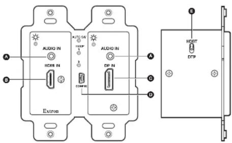
Figure 4. DTP T DWP 4K D Series Front Panel Connectors and Side Panel
Audio input connector — Connect an unbalanced stereo audio source to this 3.5 mm mini stereo jack. The image to the
Tip Left (+) Ring Right (-)
Rear Panel
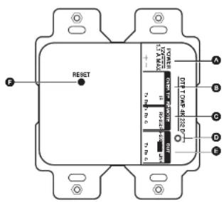
Figure 5. DTP T DWP 4K D Series Rear Panel Connectors
A DC power input connector — Plug the included external 12 VDC power supply into either this 2-pole connector (see Power Supply Wiring on page 9 to wire the power connector) or the power input connector on the receiver (see the user guide of your receiver for more information).
B Over TP control port — Connect an RS-232, IR, or both devices to this 5-pole, 3.5 mm captive screw connector for pass-through RS-232 or IR control (see RS-232 and IR Connector Wiring on page 11 to properly wire the RS-232 connector).
Remote (RS-232) control port — Connect an RS-232 device to this 3-pole, 3.5 mm captive screw connector for SIS configuration and firmware updates (see RS-232 and IR Connector Wiring on page 11 to properly wire the Remote connector).
- RS-232 — To control the unit through this port, connect an RS-232 device and configure it as follows: 9600 baud rate, 8 data bits, 1 stop bit, no parity.
- IR — Bidirectional TTL level (0 to 5 V) modulated infrared from 30 kHz to 60 kHz.
D Ground point — Use the included grounding strap to ground the unit (see Site Preparation and Wall Box Installation on page 4 for more information).
B NTD Out wait Connect one and of the twisted pair able to the 11.45 connector on
Twisted Pair Recommendations for DTP Communication
Use the following pin configurations for shielded twisted pair cables.
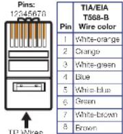
Figure 6. Twisted Pair Cable Configuration
Supported Cables
The extenders are compatible with shielded twisted pair cable (F/UTP, SF/UTP, and S/FTP).
ATTENTION:
Cable Recommendations
Extron recommends using the following practices to achieve full transmission distances and reduce transmission errors.
- Use the following Extron XTP DTP 24 SF/UTP cables and connectors for the best performance:
• XTP DTP 24/1000 Non-Plenum 1000' (305 m) spool 22-236-03
Power Supply Wiring
NOTES:
- Only one power supply is required. A single power supply connected to either unit in the pair powers both units.
- A power supply is included with each individually-packaged transmitter.
- Do not tin the power supply leads before installing them in the direct insertion connector. Tinned wires are not as secure in the connectors and could be pulled out.
Figure 10 shows how to wire the connector.
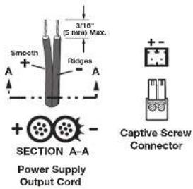
Figure 7. Power Connector Wiring
CAUTION: The wires must be kept separate while the power supply is plugged in. Remove power before wiring.
RS-232 and IR Connector Wiring
Over TP RS-232 and IR Connector
Wire the rear Over TP RS-232/IR connector as shown in figure 8.
Connected RS-232 and
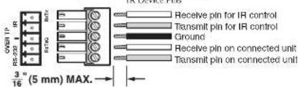
Figure 8. Over TP Connector Wiring
NOTE: Do not tin the wires before installing them in the direct insertion connector.
Tinned wires are not as secure in the connectors and could be pulled out.
Remote RS-232
Wire the rear Remote RS-232 connector as shown in figure 9.
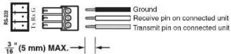
Figure 9. Remote RS-232 Connector Wiring
Operation
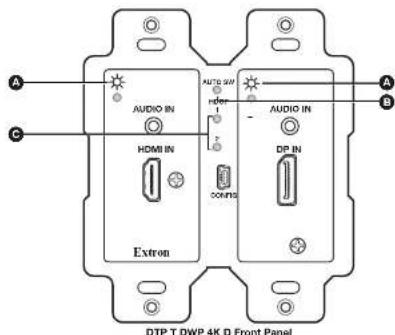
Figure 10. Transmitter LED Indicators
Transmitter LEDs
Power LEDs — Two-color front panel LEDs on the transmitters light to indicate signal and power status as follows:
- Amber — The unit is receiving power but there is no signal on the associated input.
- Green — The unit is receiving power and a signal is present on the associated input.
NOTE: Both inputs on the transmitters have their own separate LEDs.
Auto Switch LED — Lights steadily when auto switch is active.
© HDCP LEDs — Light steadily when HDMI (LED 1) or DisplayPort (LED 2) input has been authenticated on the source device.
Audio Configuration
The DTP T DWP 4K D series of products can embed analog audio inputs onto the digital video output.
NOTE: If no HDMI or DisplayPort signal is present, analog audio is transported over the DTP connection to the analog audio output of the receiver.
When an input is selected, audio transport over HDMI or DisplayPort can be configured to operate in one of three modes. Each input can be configured individually for any of the three modes.
- Transport digital embedded audio (default) — The digital embedded audio content on the digital video input is transported. Analog audio is still separate from the digital embedded audio on the HDMI or DisplayPort signal and transported simultaneously over the DTP output, not embedded onto the digital output.
- Embed analog audio input — The analog audio input is always embedded to the digital output, replacing whatever content is already present on the digital embedded audio. Analog audio is also transported over the DTP output as a simultaneous output.
- Auto select between analog audio and digital embedded audio — When both analog audio and digital embedded audio on HDMI or DisplayPort are present, embedded digital audio on the HDMI or DisplayPort signal takes priority. Analog audio is transported simultaneously with the digital embedded audio content that is already present on the DTP output.
Remote Control
This section includes:
- Simple Instruction Set Control
• Command and Response Table for SIS Commands
Simple Instruction Set Control
The DTP T DWP 4K D series of extenders can be remotely controlled using SIS commands from a host device such as a computer or control system via its rear panel Remote RS-232 port (see C on page 7) or front panel Configuration (USB) port (see D on page 6).
The default serial port protocol of the RS-232 port is as follows:
9600 baud
• No parity
- 8 data bits
- No flow control
1 stop bit
Host-to-Extender Communications
SIS commands consist of one or more characters per field. No special characters are required to begin or end a command character sequence. When a command is valid, the extender executes the command and sends a response to the host device. All responses from the extender to the host end with a carriage return and a line feed (CR/LF = ⬆), which signals the end of the response character string. A string is one or more characters.
Transmitter-Initiated Messages
When a local event occurs, such as a front panel operation, loss or restoration of an input signal, or an error condition, the extender responds by sending a message to the host.
Error Responses
When the extender receives a valid SIS command, it executes the command and sends a response to the host device. If the extender is unable to execute the command because the command is invalid or it contains invalid parameters, the extender returns an error response to the host. The error response codes are:
E01 — Invalid input channel number (out of range)
E06 — Invalid channel change
E10 — Invalid command
E13 — Invalid parameter
Timeout
Pauses of 10 seconds or longer between command ASCII characters result in a timeout. The command operation is aborted with no other indication.
EDID
User assigned mode
In user assigned mode, the user can select from 22 factory loaded EDID files, each categorized by rate type (IT or CE), video format (DVI or HDMI), audio type (2-Ch), and native resolution. The unit retains this setting after a power cycle.
Additionally, two user-loaded slots are available to save the EDID of any connected display. EDID saved to these slots are retained after a power cycle. Upon a factory reset, these EDID revert to the factory default (720p @ 60 Hz, 2-Ch audio).
A table showing the factory loaded EDID options is shown on the following page. The EDID memory location is labelled for consistency with the value in the SIS commands.
TMDS Output Format
The TMDS output format has three components:
• Video format (HDMI or DVI)
• Colorspace /RGB 4·4·4 YI IV 4·2·2 or YI IV 4·4·4
DTP T DWP 4K D EDID Memory Locations
| KD | Native Resolution | Refresh Rate | Type Video | Format Audio Type | |
| 1 | 1280x800 60 Hz IT HDMI | 2-Ch | |||
| 2 | 1440x900 60 Hz IT HDMI | 2-Ch | |||
| 3 | 1600x900 60 Hz IT HDMI | 2-Ch | |||
| 4 | 1680x1050 60 Hz IT HDMI | 2-Ch | |||
| 5 | 1920x1200 60 Hz IT HDMI | 2-Ch | |||
| 6 | 2560x1440 60 Hz IT HDMI | 2-Ch | |||
| 7 | 2560x1600 60 Hz IT HDMI | 2-Ch | |||
| 8 | 720p 50 Hz | CE | HDMI | 2-Ch | |
| 9^1 | 720p | 60 Hz | CE | HDMI | 2-Ch |
| 10 | 1080p | 50 Hz | CE | HDMI | 2-Ch |
| 11 | 1080p | 60 Hz | CE | HDMI | 2-Ch |
| 12 | 4K / UHD | 30 Hz | CE | HDMI | 2-Ch |
| 13^2 | 1280x720 | 60 Hz | IT | DisplayPort | 2-Ch |
| 14 | 1280x800 60 Hz IT | DisplayPort | 2-Ch | ||
| 15 | 1440x900 60 Hz IT | DisplayPort | 2-Ch | ||
| 16 | 1600x900 60 Hz IT | DisplayPort | 2-Ch | ||
| 17 | 1680x1050 60 Hz IT | DisplayPort | 2-Ch | ||
| 18 | 1920x1080 60 Hz IT | DisplayPort | 2-Ch | ||
| 19 | 1920x1200 60 Hz IT | DisplayPort | 2-Ch | ||
| 20 | 2560x1440 60 Hz IT | DisplayPort | 2-Ch | ||
| 21 | 2560x1600 60 Hz IT | DisplayPort | 2-Ch | ||
| 22 | 3840x2160 30 Hz IT | DisplayPort | 2-Ch | ||
| 23 | Output 1 | ||||
| 24 | User Loaded Slot 1 | ||||
| 25 | User Loaded Slot 2 | ||||
| HDMI Default; *DisplayPort Default | |||||
Using the Command and Response Table
The Command and Response Table begins on page 19. Symbols are used throughout the table to represent variables in the command and response fields. Command and response examples are shown throughout the table. The ASCII to HEX conversion table below is for use with the command and response table.
NOTE: Upper and lowercase text can be used interchangeably unless otherwise stated.
| Space → | ASCII to Hex Conversion Table | Esc 1B | CR 0D | LF 0A | |||||||
| 20 | 1 | 21 | 22 | # | 23 | $ | 24 | % 25 | & 26 | ' 27 | |
| ( 28 ) | 29 | * 2A | + | 2B | . | 2C | - 2D | . 2E | / 2F | ||
| ∅ 30 | 1 | 31 | 2 | 32 | 3 | 33 | 4 | 34 | 5 35 | 6 36 | |
| 8 38 | 9 | 39 | : 3A | ; | 3B | < | 3C | = 3D | > 3E | ? 3F | |
| @ 40 | A | 41 | B | 42 | C | 43 | D | 44 | E 45 | F 46 | |
| H 48 | : | 49 | J | 4A | K | 4B | L | 4C | M 4D | N 4E | |
| P 50 | Q | 51 | R | 52 | S | 53 | T | 54 | U 55 | V 56 | |
| X 58 | Y | 59 | Z | 5A | [ 5B ] | 5C | ] | 5D | ^ 5E | _ 5F | |
| ` 60 | a | 61 | b | 62 | c | 63 | d | 64 | e 65 | f 66 | |
| h 68 | i | 69 | j | 6A | k | 6B | l | 6C | m 6D | n 6E | |
| p 70 | q | 71 | r | 72 | s | 73 | t | 74 | u 75 | v 76 | |
| x 78 | y | 79 | z | 7A | { 7B ] | l | 7C | } 7D | - 7E | DEL 7F | |
Symbol definitions
← = Carriage return/line feed
← = Carriage return (no line feed)
I = Pipe (can be used interchangeably with the character)
- = Space
Esc = Escape key
W = Can be used interchangeably with the Eso character
x1 = Input number ∅
= deselect input (break tie, disables output)
1 = HDMI,
2 = DisplayPort
∅ = off, disabled, or not detected
1 = on, enabled, or detected
∅ = disabled (default)
1 = enabled (highest active input has priority)
2 = enabled (lowest active input has priority)
x13 = Embedded audio input format
x14 = DTP/HDBaseT switch position
X15 = Output HDCP mode
X16 = TMDS output format
∅ = auto (default)
1 = force existing digital/embedded audio
2 = force embedding of analog audio
∅ = DTP (default)
1 = HDBaseT
= Encrypt as required by input. Continuous trials for HDMI sinks, attempts for 10s on DVI sinks, then fail (default)
1 = Always encrypt. Continuous trials for HDMI sinks, attempts for 10s on DVI sinks, then fail
2 = Encrypt as required by input. Continuous trials for HDMI and DVI sinks
3 = Always encrypt. Continuous trials for HDMI and DVI sinks
∅ = Auto (default)
1 = DVI RGB 444
2 = HDMI RGB "Full"
3 = HDMI RGB "Limited"
4 - HDMI YI IV 444 "Full"
5 = HDMI YUV 444 "Limited"
6 - HDMI YUV 422 "Full"
7 = HDMI YUV 422 "Limited"
Command and Response Table for SIS Commands
| Command ASCII Command(host to unit) | Response(unit to host) | Additional Description | |
| Input Selection (unsolicited) | |||
| Select input | ! In •All← | ||
| Query input | ! | In •All← | Verbose mode 2/3 |
| Select video breakaway | % In •Vid← | Select HDMI/DP input only, independent from analog audio | |
| Query video breakaway | % | In •Vid← | Verbose mode 2/3 |
| Select analog audio breakaway | In\boxed{XI}•Aud← | Select analog audio only, independent from HDMI/DP | |
| Query analog audio breakaway | In •Aud← | Verbose mode 2/3 | |
| Auto Switch Mode (unsolicited) | |||
| Disable | 0AUSW Ausw0← | ||
| Priority to highest active input | 1AUSW Ausw1← | ||
| Priority to lowest active input | 2AUSW Ausw2← | ||
| Query Auto switch setting | ← | AuswXC← | Verbose mode 2/3 |
| Video Mute | |||
| Enable video mute | 1B Vmt1← | Mute video and display black video | |
| Disable video mute | ∅B Vmt0← | ||
| Query video mute status | B 2 ← | Display video mute status | |
| Vmt 2 ← | Verbose Mode 2/3 | ||
Audio Input Format
| Command ASCII Command(host to unit) | Response(unit to host) | Additional Description | |
| Analog Audio Mute | |||
| Enable/disable analog audio mute | XZAmtx2← | ||
| Query analog audio mute status | ZX2← | Display analog Audio mute status | |
| Amtx2← | Verbose Mode 2/3 | ||
| Embedded (HDMI) Audio Output Mute | |||
| Embedded audio mute | EscX2AFMT←Afmtxx← | Mute embedded audio | |
| Query analog audio mute status | EscAFMT←X2← | Display embedded audio mute status | |
| Afmtx2← | Verbose Mode 2/3 | ||
| Video Output Color Bit Depth | |||
| Set video bit depth mode | EscV80BITD←BitdV80← | ||
| Query video bit depth for outputs | EscVBITD←X9← | ||
| BitdV89← | Verbose Mode 2/3 | ||
| Signal Status (unsolicited) | |||
| Request all signal status | EscOLS← | X2*X2*X3SigX2*X2*X2← | Input 1 • Input 2 * Output |
| Verbose Mode 2/3 | |||
| HDCP Status (unsolicited) | |||
| View HDCP status for specific input | EscIX1HDCP←X5 | HdcpIX5← | Verbose Mode 2/3 |
| View HDCP status for all inputs | EscIHDCP←X5 | HdcpIX5*X5← | Unsolicited |
| Verbose Mode 2/3 | |||
| Query output HDCP status | EscOHDCP←X5 | HdcpOx6← | Unsolicited |
| Verbose Mode 2/3 | |||
| HDCP Authorized Device | |||
| HDCP authorization onable/ disable per input | EscEX1*X2HDCP← | HdcpEX1*X2← | |
| HDCP authorization enable/ | EscEX2HDCP←HdcpEX2← | Default | |
| HDCP Output Mode | |||
| Set output HDCP mode | EscSX15HDCP← HdcpSX15← | ||
| Query output HDCP mode | EscSHDCP← X13← | ||
| HdcpSX16← | Verbose Mode 2/3 | ||
| TMDS Output Format | |||
| Set format | EscX16VTP0← VtpoX16← | ||
| Query format | EscVTP0← X18← | ||
| VtpoX19← | Verbose Mode 2/3 | ||
| EDID Minder | |||
| Assign EDID to input | EscAX1*XCEDID← | EdidAX1*K4← | KD= EDID memory location (1-16)soe the DTP T DWP 4K D EDIDMemory Locations table on page 16 |
| View EDID assignment | EscAX1EDID← | X4← | Display currently assigned EDID |
| EdidAX1*K4← | Verbose Mode 2/3 | ||
| View/Rcad EDID in Hex | EscRX1EDID← | X8← | Display currently assigned EDID in Hex |
| View EDID native resolution | EscNX1EDID← | X11← | Resolution and refresh rate of currently selected EDIDExample: 1600x1200@60Hz |
NOTES:
| X1 = Input number | ∅ = deselect input (break tie, disable output) |
| 1 = HDMI | |
| 2 = DisplayPort | |
| X4 = EDID slot | See DTP T DWP 4K D EDID Memory Locations on page 16. |
| X8 = Raw EDID data | 128 or 256 bytes of hexadecimal data |
| X11 = Current EDID native resolution and refresh rate in plain text | |
| Command ASCII Command(host to unit) | Response(unit to host) | Additional Description | |
| Device Name | |||
| Set device name | EscX7CN← Ipn•X7← | X7= Up to 24 alphanumeric characters, including "-" | |
| Set unit name to factory default | Esc•CN← | Ipn•{Default}← | Example:DTP-T-DWP-4K-D |
| View unit name | EscCN← | X7← | |
| Other | |||
| Information request | I InX1Vid• | InX1Aud• AuswX3• VmtX2•AmtX2← | |
| Set verbose mode | EscX12CV← | VrbX12← | ∅-3 (1 is default) |
| Query verbose mode | EscCV← | X12← | |
| VrbX12← | Verbose Mode 2/3 | ||
| Query DTP mode | Esc01HDBT← X14← | Hdbt01*X14← | Verbose Mode 2/3 |
| Request part number | N 60-1498-12← | 60-1498-52← | DTP T DWP 4K 232 D DTP T DWP 4K 332 D |
| Query firmware version | Q x.xx← | ||
| Query firmware version with build | *Q x.xx.xxxx← | Firmware build with 2 decimals | |
| Reset settings | EscZXXX← Zpx← | ||
NOTES:
| X1 = Input number | ∅ = deselect input (break tie, disable output) |
| 1 = HDMI | |
| 2 = DisplayPort | |
| X2 = Status | ∅ = off, disabled, or not detected |
| 1 = on, enabled, or detected |
Reference Information
This section includes decorator-style wallplate template dimensions for installation of the DTP T DWP 4K D Series of transmitters.
Decorator-Style Wallplate Template Dimensions
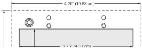
To create a template, use the dimensions shown on figure 11.
NOTES:
- The drawing is not full size or to scale. DO NOT scale up or print to use as a template.
• Full size templates are available at www.extron.com.
Template for the 2-gang mounting bracket
Extron Warranty
Extron Electronics warrants this product against defects in materials and workmanship for a period of three years from the date of purchase. In the event of malfunction during the warranty period attributable directly to faulty workmanship and/or materials, Extron Electronics will, at its option, repair or replace said products or components, to whatever extent it shall deem necessary to restore said product to proper operating condition, provided that it is returned within the warranty period, with proof of purchase and description of malfunction to:
and Central America:
Extron Electronics
1230 South Lewis Street
Anaheim, CA 92805
U.S.A.
Japan:
Extron Electronics, Japan
Kyodo Building, 16 Ichibancho
Chiyoda-ku, Tokyo 102-0082
Japan
Europe and Africa:
Extron Europe
Hanzeboulevard 10
3825 PH Amersfoort
The Netherlands
China:
Extron China
686 Ronghua Road
Songjiang District
Shanghai 201611
China
Asia:
Extron Asia Pte Ltd
135 Joo Seng Road, #04-01
PM Industrial Bldg.
Singapore 368363
Singapore
Middle East:
Extron Middle East
Dubai Airport Free Zone
F13, PO Box 293666
United Arab Emirates, Dubai
This Limited Warranty does not apply if the fault has been caused by misuse, improper handling care, electrical or mechanical abuse, abnormal operating conditions, or if modifications were made to the product that were not authorized by Extron.
NOTE: If a product is defective, please call Extron and ask for an Application Engineer to receive an RA (Return Authorization) number. This will begin the repair process.
- DTP T DWP 4K D Series
- Safety Instructions
- Conventions Used in this Guide
- Notifications
- Software Commands
- Contents
- Introduction....1
- Installation and Operation....3
- Remote Control....14
- Reference Information 23
- Introduction
- About this Guide
- Terms Used in this Guide
- About the DTP T DWP 4K D Series Extenders
- Twisted Pair Cable Advantages
- Transmission Distance
- Features
- Installation and Operation
- Mounting the Transmitter
- ATTENTION:
- Site Preparation and Wall Box Installation
- NOTES:
- Mud Ring Installation
- Final Installation
- DTP T DWP 4K D Series Connections
- Rear Panel
- Twisted Pair Recommendations for DTP Communication
- Supported Cables
- Cable Recommendations
- Power Supply Wiring
- RS-232 and IR Connector Wiring
- Over TP RS-232 and IR Connector
- Remote RS-232
- Operation
- Transmitter LEDs
- Audio Configuration
- Remote Control
- Simple Instruction Set Control
- Host-to-Extender Communications
- Transmitter-Initiated Messages
- Error Responses
- Timeout
- EDID
- User assigned mode
- TMDS Output Format
- Using the Command and Response Table
- Symbol definitions
- Reference Information
- Decorator-Style Wallplate Template Dimensions
- Extron Warranty
- and Central America:
- Japan:
- Europe and Africa:
- China:
- Asia:
- Middle East:
Brand : Extron
Model : DTP T DWP 4K 232 D
Category : Wall socket