
IPCP 505 - AV Controller Extron - Free user manual and instructions
Find the device manual for free IPCP 505 Extron in PDF.


| Product Type | AV Controller |
| Brand | Extron |
| Model | IPCP 505 |
| Dimensions (H x W x D) | 1.7" x 17.0" x 7.0" (4.3 cm x 43.2 cm x 17.8 cm) |
| Weight | 3.5 lb (1.6 kg) |
| Power Supply | 100-240 VAC, 50/60 Hz, internal |
| Power Consumption | 15 watts (max) |
| Ethernet Ports | 2 x RJ-45 (1 LAN, 1 control) |
| Serial Ports | 2 x RS-232 (front/rear) |
| IR Ports | 2 x IR (1 in, 1 out) |
| Relay Ports | 4 x relay (dry contact) |
| Digital I/O | 4 x digital input/output |
| Audio Breakaway | Supported |
| Control Protocol | TCP/IP, UDP, Telnet, HTTP, SNMP |
| Compatible Software | Extron Global Configurator Plus/Pro |
| Mounting | Rack-mountable (1U), included brackets |
| Cooling | Fanless, natural convection |
| Operating Temperature | 32°F to 122°F (0°C to 50°C) |
| Humidity Tolerance | 10% to 85%, non-condensing |
| Maintenance & Cleaning | Wipe with dry cloth; avoid liquids |
| Safety Standards | UL, CE, FCC Class A |
| Spare Parts & Repairability | Contact Extron support; power supply is replaceable |
| General Information | IPCP 505 is an IP-based control processor for AV systems, featuring built-in Ethernet, serial, and IR control. |
Frequently Asked Questions - IPCP 505 Extron
User questions about IPCP 505 Extron
0 question about this device. Answer the ones you know or ask your own.
Ask a new question about this device
Download the instructions for your AV Controller in PDF format for free! Find your manual IPCP 505 - Extron and take your electronic device back in hand. On this page are published all the documents necessary for the use of your device. IPCP 505 by Extron.
USER MANUAL IPCP 505 Extron
IP Link Control Processor

Safety Instructions
Safety Instructions • English
WARNING: This symbol, , when used on the product, is intended to start the user of the presence of uninsulated dangerous voltage within the product's enclosure that may present a risk of electric shock.
ATTENTION: This symbol, when used on the product, is intended to alter the user of important operating and maintenance (servicing) instructions in the literature provided with the equipment.
For information on safety guidelines, regulatory compliance, LMI-LMI compatibility, accessibility, and related topics, see the Extron Safety and Regulatory Compliance Guide, part number 58.290.01, on the Extron website, www.extron.com.
Chinese Simplified (简体中文)
Chinese Traditional (繁體中文)
This equipment has been tested and found to comply with the limits for a Class A digital device, pursuant to part 15 of the FCC rules. The Class A limits provide reasonable protection against harmful interference when the equipment is operated in a commercial environment. This equipment generates, uses, and can radiate radio frequency energy and, if not installed and used in accordance with the instruction manual, may cause harmful interference to radio communications. Operation of this equipment in a residential area is likely to cause interference; the user must correct the interference at his own expense.
NOTE: For more information on safety guidelines, regulatory compliances, EMI/EMF compatibility, accessibility, and related topics, see the Extron Safety and Regulatory Compliance Guide on the Extron website.
Conventions Used in this Guide
Notifications
The following notifications are used in this guide:
WARNING: A warning indicates a situation that has the potential to result in death or severe injury.
CAUTION: A caution indicates a situation that may result in minor injury.
ATTENTION: Attention indicates a situation that may damage or destroy the product or associated equipment.
NOTE: A note draws attention to important information.
TIP: A tip provides a suggestion to make working with the application easier.
Software Commands
Commands are written in the fonts shown here:
^AR Merge Scene,,Op1 scene 1,1 ^B51 ^W^C
[01] R000400300004000080000600 [02] 35 [17] [03]
Esc X1 * X17 * X20 * X23 * X21 CE
NOTE: For commands and examples of computer or device responses mentioned in this guide, the character "0" is used for the number zero and "0" is the capital letter "o."
Computer responses and directory paths that do not have variables are written in the font shown here:
Reply from 208.132.180.48: bytes=32 times=2ms TTL=32
a 1 = -1.5 1 =
Contents
Introduction 1
Before You Begin....1
About the IPCP 505 ....1
Features 1
Controlling Other Devices 2
Application Diagrams....3
IR and RS-232 Device Control....4
How the IPCP 505 Works: Components and
teractions....5
Creating a Control System Using the IPCP with
Optional Extron TouchLink Touchpanels.... 5
System Requirements 6
Hardware Requirements 6
Software Requirements 6
Hardware Features and Installation 7
Setup Checklist:
How to Proceed With Installation....7
Prepare....7
Perform Physical Installation 7
Configure the IPCP 7
Front Panel Features....9
Software-based
Configuration and Control ....18
Configuration and Control: an Overview.....18
Basic Setup Steps: a Guide to this Section and
Other Resources 19
Communicating with the IPCP 19
Configuring the IPCP for Network
Communication....19
Configuring the IPCP for Network Use
Via Global Configurator....20
Configuring the IPCP for Network Use
Via the ARP Command....20
Configuring the IPCP for Network Use
Via SIS Commands and Telnet....23
Setting up the PC for IP Communication
With an IPCP 505....23
Global Configurator Software for Windows ^® ..... 27
Downloading the Software and
Getting Started 27
PC System Requirements....27
Using Global Configurator: Helpful Tips...... 28
SIS Programming and Control....50
Host-to-IPCP Communications 50
IPCP 505-initiated Messages....50
Password Information....51
Error Responses....51
Error Response References 51
Commands and Responses 51
Using the Command/Response Tables.....51
Entering SIS Commands: Helpful Tips ..... 52
Symbol Definitions....53
Command/Response Table for
SIS Commands 57
Firmware Updates....78
Determining the Firmware Version....78
Using the Global Configurator Software ..... 78
Updating the Main Firmware 81
Locating and Downloading the Firmware ..... 81
Updating Firmware via Extron IP Link
File Manager Software 82
Updating Firmware via the IPCP
Embedded Web Page 83
Updating Firmware via Extron
Firmware Loader Software....85
Reference Information 75
Glossary 75
File Types: a Key to Extron-specific File Names... 77
Index 86
Introduction
This section covers the following basic information you should know about this guide and the product before installation:
- Before You Begin — What this guide covers and does not cover, and what terms are used to refer to this product
• About the IPCP 505 — An overview of the product and its features
• Application Diagrams — Example application diagrams - IR and RS-232 Device Control — General information about IR and RS-232 control of other products
- How the IPCP 505 Works: Components and Interactions — A conceptual explanation of how it works
- Creating a Control System Using the IPCP with Optional Extron TouchLink Touchpanels — A brief overview about using the IPCP with touchpanels
- System Requirements — Computer and network system requirements for setting up an IPCP
Before You Begin
This guide provides detailed information and best practices recommendations about cabling and configuring the Extron IPCP 505 IP Link Control Processor and reference information about controller specifications, programming, and applications.
It does not contain instructions on the most basic setup steps: those are covered in the Global Configurator Help file, which describes how to use the Global Configurator (GC) program to download drivers, add AV devices to a GC configuration, configure functions, set a shutdown schedule, and set up e-mail alerts to flag a projector disconnection or warn that lamp usage hours have been exceeded.
Throughout this guide the IPCP 505 is also referred to as the "IPCP," "control processor," or "controlless" Global Configuration software in also referred to as "CC," and the GlobalFocus
Network and configuration features
The IPCP 505 can be configured and controlled using a host computer via IP Link Ethernet control. Setup and control can be accomplished by simple ASCII commands (Simple Instruction Set, SIS ^™ ) or via the free Global Configurator (GC) program. The GC software offers many more setup options than does SIS programming. After being configured, the IPCP can be controlled by a TouchLink touchpanel connected to the same network.
The IPCP 505 integrates seamlessly with Extron GlobalViewer Enterprise (GVE) software and the free GlobalViewer web-based AV resource management and remote control application. The IPCP supports multiple TouchLink touchpanels over a standard Ethernet network. Global Configurator and other useful software applications are available at www.extron.com.
Via Ethernet/IP communication you can access the embedded web pages of the IPCP 505, which include online diagnostics and monitoring of basic control features. As an integrated part of the IPCP 505, IP Link provides the following advantages:
- Global compatibility — The IPCP uses standard Ethernet communication protocols, including ARP, DHCP, ICMP (ping), TCP, IP, Telnet, HTTP, and SMTP.
- Embedded web page serving — The IPCP 505 offers up to 975 MB of flash memory for storing Extron GlobalViewer and user-supplied web pages, configuration settings, and device drivers. Data in flash memory is served at a transfer rate of 6 Mbps (mogabits per second).
- Remote equipment management — The IP Link connection allows you to remotely manage, monitor, and control up to eight Ethernet-enabled products such as projectors, cameras, video conferencing equipment, switchers, and other AV equipment. The IPCP provides support for the following:
• TCP connections only
• Password-protected TCP connections
• Up to eight Ethernet drivers at a time
• Connection via IP address or host name
• A range of Telnet ports, when supported by the target device
- Multi-user support — Up to two hundred (200) simultaneous connections enable each IP Link device to support many concurrent users and improve system throughput by sending information in parallel.
Application Diagrams
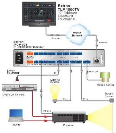
The following figures show examples of types of devices that can be connected to some of the ports on the IPCP 505.
flowchart
graph TD
    A["Extron TLP 1000TV 10" Tablettop TouchLink Touchpanel"] --> B["Extron IPCP 605 1.1 Link Control Processor"]
    B --> C["Extron IR Emitter"]
    C --> D["DrDPVCH Combo"]
    D --> E["Laptop"]
    E --> F["ProWater"]
    F --> G["Digital 2D"]
    G --> H["Motion Sensor"]
    H --> I["Screen Channel"]
    B --> J["Ethernet"]
    B --> K["Ethernet"]
    B --> L["Ethernet"]
    B --> M["Ethernet"]
    B --> N["Ethernet"]
    B --> O["Ethernet"]
    B --> P["Ethernet"]
    B --> Q["Ethernet"]
    B --> R["Ethernet"]
    B --> S["Ethernet"]
    B --> T["Ethernet"]
    B --> U["Ethernet"]
    B --> V["Ethernet"]
    B --> W["Ethernet"]
    B --> X["Ethernet"]
    B --> Y["Ethernet"]
    B --> Z["Ethernet"]
    B --> AA["Ethernet"]
    B --> AB["Ethernet"]
    B --> AC["Ethernet"]
    B --> AD["Ethernet"]
    B --> AE["Ethernet"]
Figure 1. An Example Application

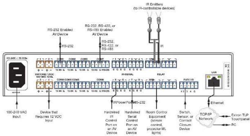
Figure 3. Signal Flow and Generic Connection Types
IR and RS-232 Device Control
The IPCP must be configured in one of the following ways before it will send commands to a projector, display, or source device:
- An IR or an RS-232 driver file can be installed from a disk, downloaded from the Extron website (www.extron.com), or downloaded from the extensive Extron driver library using the driver subscription feature within Global Configurator. The driver is saved to a folder and uploaded to the IPCP via Global Configurator.
How the IPCP 505 Works: Components and Interactions
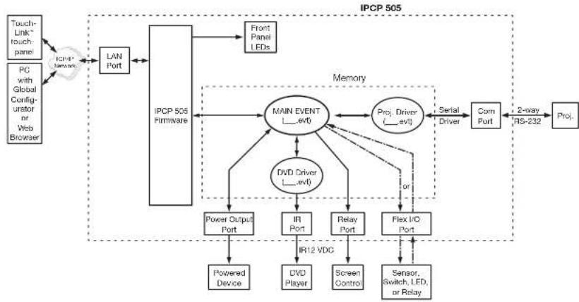
The IPCP1505 requires and uses event files to perform functions. The event files define, monitor, and govern how an IPCP1505 works. The following diagram is an example of how the IPCP interacts with accessories, event scripts, drivers, ports, input devices, and output devices.
flowchart
graph TD
    A["Touch-Link touch-panel"] --> B["IPCN Network"]
    C["PC with Global Configurator or Web Browser"] --> B
    B --> D["LAN Port"]
    D --> E["IPC P 505 Firmware"]
    E --> F["Main EVENT __evl"]
    F --> G["DVD Driver __evl"]
    F --> H["Proj. Driver __evl"]
    H --> I["Serial Driver"]
    I --> J["Com Port"]
    J --> K["2-way RS-232"]
    K --> L["Prol."]
    F --> M["Power Output Port"]
    F --> N["IR Port"]
    F --> O["Relay Port"]
    F --> P["Flex I/O Port"]
    M --> Q["Powered Device"]
    N --> R["DVO Player"]
    O --> S["Screen Control"]
    P --> T["Sensor, Switch, LED, or Relay"]
    style E fill:#f9f,stroke:#333
    style F fill:#ccf,stroke:#333
    style H fill:#cfc,stroke:#333
    style I fill:#fcc,stroke:#333
    style J fill:#cff,stroke:#333
    style K fill:#ffc,stroke:#333
Figure 4. How the IPCP 505 Works
The IPCP can be configured completely via Global Configurator software. Once you have set up how you want it to work (assigned drivers to ports, configured relays and contact closure input, and set up IP addresses and functions), that information is saved to a project file that is unloaded into the IPCP.
System Requirements
The IPCP 505, Global Configurator, and GUI Configurator have the following minimum hardware and software requirements:
Hardware Requirements
| Global Configurator GUI Configurator | ||
| Processor Intel | 2 Pentium3 Ill. 1 GHz Intel Pentium 4 or AMDTM AthlonTM | |
| RAM 512 MB 1 GB (2 GB is recommended for multiple or large projects) | ||
| Available hard disk space | 50 MB 100 MB | |
| Screen resolution 1024x768 | ||
| A network connection with a minimum data transfer rate of 10 Mbps(100 Mbps is recommended) | ||
Software Requirements
| Global Configurator and GlobalViewer | GUI Configurator | |
| Operating system • Microsoft Windows XP, service pack 2• Windows Vista or• Windows 7 | • Microsoft Windows XP, service pack 3• Windows Vista or• Windows 7 | |
| ATTENTION: Do not run Global Configurator software on a PC that uses an earlier version of Windows. | ||
Hardware Features and Installation
This section covers the following material:
- Setup Checklist: How to Proceed With Installation — A checklist of tasks to guide you through installation
- Front Panel Features — Locations and some descriptions of items on the front panel
- Mounting the IPCP 505 – Brief guidelines for mounting
- Rear Panel Features and Connections — Locations, descriptions, and cabling notes for rear panel features and corresponding front panel indications
- Resetting the Unit — Information about the available reset modes and how to reset the IPCP
Setup Checklist:
How to Proceed With Installation
Prepare
Familiarize yourself with the features of the IPCP 505.
☐ Install the latest version of the Extron Global Configurator (GC) software (version 3.2 or higher), the latest driver package, and any additional software such as GUI Configurator, GlobaViewer Enterprise (GVE) or IR Learner (available from www.extron.com or the Extron Software Products disc).
☐ Obtain IP setting information from the network administrator for the IPCP.
☐ Obtain model names and return information for devices that the IBO will control
☐ Create a new GC project and configure the IPCP 505. See the Global Configurator Help file.
☐ Set the IP address and subnet mask for the IPCP, and other IP settings.
☐ Define the GlobalViewer Tree location of the unit.
☐ Add the IPCP to the project.
☐ Define e-mail settings and contacts.
☐ Add serial, IR, and Ethernet device drivers.
☐ Configure the ports on the IPCP and assign device drivers as needed.
☐ Configure touchpanel buttons, if applicable, in Global Configurator.
□ Create a display shutdown schedule.
☐ If a projector is part of the system and if desired, create a display lamp hours notification e-mail.
□ Create a display disconnection notification e-mail.
☐ Perform configurations for special applications, if needed.
☐ Save the Global Configurator project/configuration.
□ Build and upload the configuration.
□ Test the system.
Front Panel Features
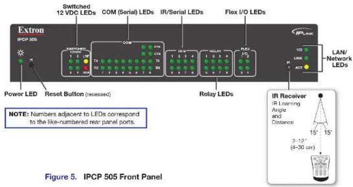
Front panel features are shown below. Most of the features and LED indications are described and shown in the "Rear Panel Features and Connections" section paired with the descriptions of the corresponding rear panel ports.
NOTE: The IPCP 505 must be set up in order to function. See the Software-based Configuration and Control section starting on page 18 and the Global Configurator Help file for information about Global Configurator, which you must use to set up the unit.
IR Learning Sensor
In most cases, Extron has already produced a driver file for controlling the projector, display, or source device you plan to use. If a device driver file is not available, you can create your own using Extron IR Learner software, the remote control of the projector or display, and the
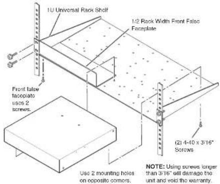
Mounting the IPCP 505
Optional rack shelves are available for use with the IPCP.
Read the instructions that come with the rack shelf or mounting kit for installation procedures
The IPCP 505 includes rubber feet so it can be set on a table. If you are going to mount the unit to a rack shelf and these feet were attached to the enclosure, remove the feet before mounting.
UL Rack Mounting Guidelines
The following Underwriters Laboratories (UL) guidelines pertain to the safe installation of the IPCP 505 in a rack.
- Elevated operating ambient temperature — If installed in a closed or multi-unit rack assembly, the operating ambient temperature of the rack environment may be greater than room ambient temperature. Therefore, install the IPCP in an environment compatible with the maximum ambient temperature (Tma = +122 °F, +50 °C) specified by Extron.
- Reduced air flow — Install the equipment in a rack so that the amount of air flow required for safe operation of the equipment is not compromised.
Rear Panel Features and Connections
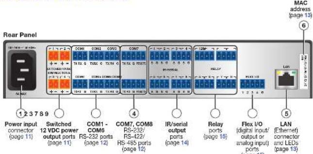
Figure 6. IPCP 505 Rear Panel
Power Connections
① Power Input connector — Connect the IPCP to a 100-240 VAC power source here.
② Switched 12 VDC power output ports — These four ports provide 12 VDC output up to a combined maximum of 40 watts. Once configured, each port can be separately turned on or off. These ports are monitored continuously for total power usage (draw).

Bidirectional Control and Communication Connections and Features
C COM1 through COM6 RS-232 ports (-5 VDC to +5 VDC) and
d COM7 and COM8 RS-232/RS-422/RS-485 ports (-5 VDC to +5 VDC) — Use
COM ports for serial control of a display or other device and to receive status messages
from the connected devices. These ports can send commands from a driver file.
IPCPJ505 serial protocol:
- 300 to 115200 baud (9600 baud = default)
- 8 (default) or 7 data bits
- 1 (default) or 2 stop bits
• No parity (default), or even or odd parity
- Flow control support
COM1-COM6: software-only (XON, XOFF)
- COM7 and COM8:
hardware and software
Use the following diagram as a wiring guide to
cable the IPCP to other devices.
TIP:
7.8 (2 cm)
316' (5 mm)
I feel Shekel or Outer Jacket on laser Conductor Transition
Extron Comm-Link Cable
Comm-Link (CTL and CTLP) cable, shown at left, is recommended
for these connections. For
best results and to avoid short circuits, use shielded wires or wires insulator
ed using heat drink (instead)
of bare wires) for
the common
drain wires.
Rear Point
| 3-201 | 4-25 | + | 7AM | TIME | TIME | OXY |
| 1 | + | 14:00 | 18:00 19:00 20:00 21:00 | |||
| 26:10:00 | ||||||
| 3 | + | 20:00 | 20:00 20:00 | |||
| 4 | + | 21:00 | 21:00 21:00 22:00 23:00 |
| Serial (COM) Ports | |
| COM1 - COM6(RS-237) | Sweet products via software or 815 command. |
| COM1-8 port defect product. | |
| COM7, COM8(RS-221, RS-427, RS-485) | • 900 card• 5 pcs bits • 1 cup bit• no parts • cable cord. |
| NOTE: The 5-pole COM ports support bothhardware and software low control.The 3-pole COM ports support softwarelow control. | |
To COM7, COM9
| CTS | Clear to send | |
| RTS | Request to send | |
| G | General | |
| Rx | Receive | Transmit (Tx) |
| Tz | Transmit | Receive (Rx) |
Project Pane Division: DC
1.35p60, R, 400ml RS-232, RS-422, cr
RS-485 Devia
RTS - Request to Send CTS = Clear or Send Tx = Transmitting Data Tx = Receiving Data
Heat Shrink
Vacc Shinà
COM7 COM8 Pan Crediennes
⑤ LAN (IP) connector and LEDs — To connect the IPCP to an Ethernet network (so you can configure and control the IPCP and the devices connected to it), plug a cable into this RJ-45 socket and connect the other end of the cable to a network switch, hub, router, or PC connected to a LAN or the Internet.
Cabling:
- For 10Base-T (10 Mbps) networks, use a CAT 3 or better cable.
• For 100Base-T (max. 155 Mbps) networks, use a CAT 5 cable.
You must configure this port before using it. Configure the settings for this port via either SIS commands or Global Configurator. See the programming sections (Software-based Configuration and Control starting on page 18 and SIS Programming and Control starting on page 50) of this guide for details on configuration.
Activity LED — This yellow LED blinks to indicate network activity.
Link LED — This green LED lights to indicate a good network connection.
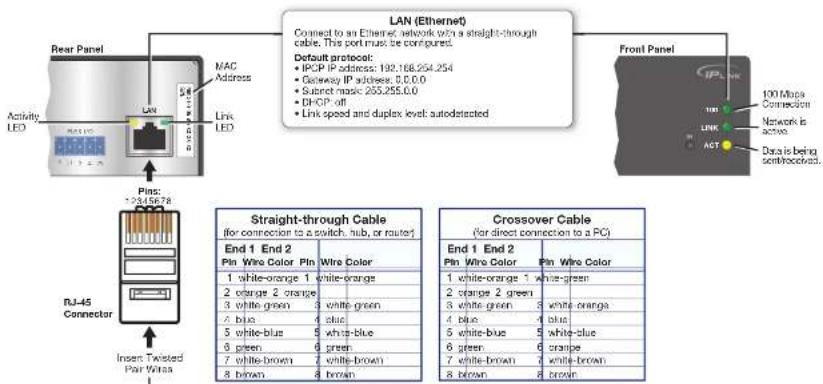
flowchart
graph TD
    A["Rear Panel"] --> B["Activity LED"]
    A --> C["Link LED"]
    A --> D["Pins: 2345678"]
    D --> E["RJ-45 Connector"]
    E --> F["Insert Twisted Pair Wire"]
    G["LAN (Ethernet)"] --> H["Connect to an Ethernet network with a straight-through cable. This port must be configured."]
    H --> I["Default protocol: IPGP IP address: 192.168.254.254; Genway IP address: 0.0.0.0; Subnet magic 255.255.0.0; DHCP off; Link speed and duplex level autodetected"]
    I --> J["Front Panel"]
    J --> K["100 Mbps Connection"]
    J --> L["Network is active"]
    J --> M["Data is being sent/recoacted."]
    N["Straight-through Cable (for connection to a switch, hub, or route)"] --> O["End 1 End 2 Pin Wire Color Pin Wire Color"]
    N --> P["Crossover Cable (for direct connection to a PC)"]
    O --> Q["1 white-orange 1 white-orange"]
    O --> R["2 orange 2 green"]
    O --> S["3 white-green 3 white-green"]
    O --> T["4 blue 4 blue"]
    O --> U["5 white-blue 5 white-blue"]
    O --> V["6 green 6 green"]
    O --> W["7 white-brown 7 white-brown"]
    O --> X["8 brown 8 brown"]
    P --> Y["End 1 End 2 Pin Wire Color Pin Wire Color"]
Unidirectional Control and Communication Connections
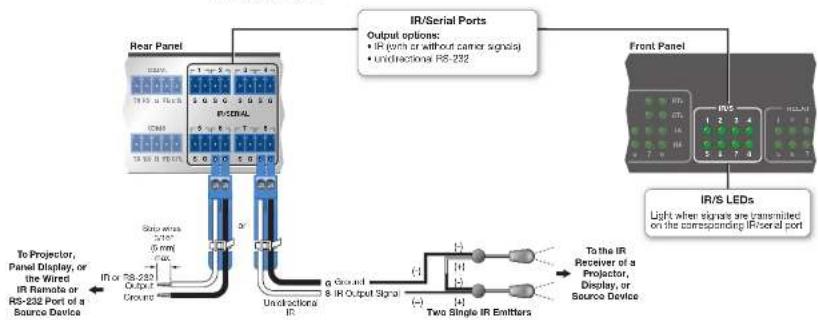
⑦ IR/Serial output ports — An IPCP 505 can use infrared signals or unidirectional RS-232 serial signals to control various devices (up to 32 total for IR) via these eight ports. Set output signal type (IR or serial) during configuration. The figure below shows wiring examples.
flowchart
graph TD
    A["IR/Serial Ports"] -->|Output options: + IR (path or without carrier signals) + undirecteds RS-232| B["Front Panel"]
    B --> C["IR/S LEDs"]
    C -->|Light when signals are transmitted on the corresponding IR/Serial port| D["Two Single IR Emitters"]
    D --> E["Ground"]
    E --> F["Stop wires 0.5V 0.8V 1.0V"]
    F --> G["Ground"]
    G --> H["To Projector, Panel Display, or the Wired IR Remote or RS-232 Port of a Source Device"]
    H --> I["Ground"]
    I --> J["Ground"]
    J --> K["Ground"]
    K --> L["Ground"]
    L --> M["Ground"]
    M --> N["Ground"]
    N --> O["Ground"]
    O --> P["Ground"]
    P --> Q["Ground"]
    Q --> R["Ground"]
    R --> S["Ground"]
    S --> T["Ground"]
    T --> U["Ground"]
    U --> V["Ground"]
    V --> W["Ground"]
    W --> X["Ground"]
    X --> Y["Ground"]
    Y --> Z["Ground"]
    Z --> AA["Ground"]
    AA --> AB["Ground"]
    AB --> AC["Ground"]
    AC --> AD["Ground"]
    AD --> AE["Ground"]
    AE --> AF["Ground"]
    AF --> AG["Ground"]
    AG --> AH["Ground"]
    AH --> AI["Ground"]
    AI --> AJ["Ground"]
    AJ --> AK["Ground"]
    AK --> AL["Ground"]
    AL --> AM["Ground"]
    AM --> AN["Ground"]
    AN --> AO["Ground"]
    AO --> AP["Ground"]
    AP --> AQ["Ground"]
    AQ --> AR["Ground"]
    AR --> AS["Ground"]
    AS --> AT["Ground"]
    AT --> AU["Ground"]
    AU --> AV["Ground"]
    AV --> AW["Ground"]
    AW --> AX["Ground"]
    AX --> AY["Ground"]
    AY --> AZ["Ground"]
    AZ --> BA["Ground"]
    BA --> BB["Ground"]
    BB --> BC["Ground"]
    BC --> BD["Ground"]
    BD --> BE["Ground"]
    BE --> BF["Ground"]
    BF --> BG["Ground"]
    BG --> BH["Ground"]
    BH --> BI["Ground"]
    BI --> BJ["Ground"]
    BJ --> BK["Ground"]
    BK --> BL["Ground"]
    BL --> BM["Ground"]
    BM --> BN["Ground"]
    BN --> BO["Ground"]
    BO --> BP["Ground"]
    BP --> BQ["Ground"]
    BQ --> BR["Ground"]
    BR --> BS["Ground"]
    BS --> BT["Ground"]
    BT --> BU["Ground"]
    BU --> BV["Ground"]
    BV --> BW["Ground"]
    BW --> BX["Ground"]
    BX --> BY["Ground"]
    BY --> BZ["Ground"]
    BZ --> CA["Ground"]
    CA --> CB["Ground"]
    CB --> CC["Ground"]
    CC --> CD["Ground"]
    CD --> CE["Ground"]
    CE --> CF["Ground"]
    CF --> CG["Ground"]
    CG --> CH["Ground"]
    CH --> CI["Ground"]
    CI --> CJ["Ground"]
    CJ --> CK["Ground"]
Figure 10. Wiring the IR/Serial Ports
Serial control: Connect one of these ports to the serial control receive (Rx) and ground pins of the device to be controlled. These ports have the same serial protocol options as the COM ports.
IR control: Connect one of those ports directly to the wired IR port of another device. Or insert the wires from up to four IR Emitters into an IR port and place the heads of the emitters over or next to the IR signal pickup windows of the devices. For wiring, see the following figures or the IR Emitter Installation Guide.
NOTE: Each emitter must be within 100 feet of the IPCP for best IR control results.
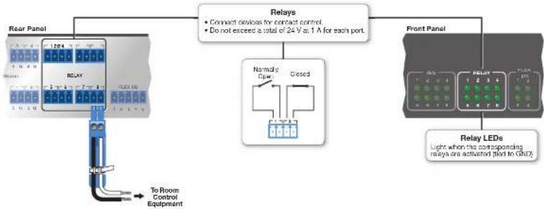
⑧ Relay ports — Eight relay ports provide control for power, screen/projector lifts, window coverings, and similar items, when trigger events occur.
flowchart
graph TD
    A["Relay Panel"] --> B["To Room Control Equipment"]
    B --> C["Relays"]
    C --> D["Normally Closed"]
    D --> E["Relay LEDs"]
    E --> F["Front Panel"]
    style A fill:#f9f,stroke:#333
    style B fill:#bbf,stroke:#333
    style C fill:#dfd,stroke:#333
    style D fill:#dfd,stroke:#333
    style E fill:#dfd,stroke:#333
    style F fill:#dfd,stroke:#333
Figure 11. Wiring the Relay Ports
These relay contacts may be used to control any equipment as long as the contact specifications of a total of 24 volts at 1 ampere are not exceeded for each port. These relays are normally open by default.
When activated, the open contacts close. They can be set up to operate in one of two ways:
- Latching (brief contact) (press to turn on, press to turn off), or
• Momentary (timed) (press to turn on, timeout to turn off).
In the timed mode the default timeout period is 12 second (500 ms). Use Global Configurator software or SIS commands to change the length of the timeout period. See the X63 variable on page 56 and the corresponding relay port commands on page 61 in the "SIS Programming and Control" section for details.
Additional Control Ports
room or light switches via an Extron IPA T RLY4, you can use one or more of those ports as a digital output. When a port is configured for digital output, it offers two output states: on and off. When the port is set to an "on" state, (the circuit is closed), the I/O pin is connected to ground. Each I/O port is capable of accepting 250 mA, maximum. When the port is set to the "off" state (the circuit is open), the output pin is not connected. If the application calls for TTL compatibility, the digital output circuit can be set up to provide a 2k ohm pull-up resistor to -5 VDC.
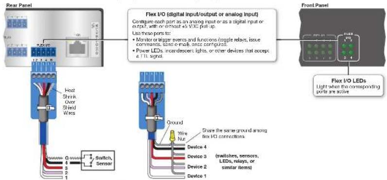
Figure 12. Flex I/O Port Wiring Examples
Resetting the Unit
There are five reset modes that are available by pressing the Reset button on the front panel. The Reset button is recessed, so use a
| IPCP Controller Reset Mode Summary | ||||
| Mode | Activation Result Purpose and | Notes | ||
| Use Factory Firmware | 1 | Hoid down the recessed Reset button while applying power to the IPCP.NOTE: After a mode 1 reset is performed, update the IPCP firmware to the latest version.Do not operate the IPCP controller firmware version that results from the mode I reset. This mode temporarily resets the unit to factory default until power is recycle. If you want to use the factory default firmware, you must upload that version again. See the Global Configurator Help file for firmware upload instructions. | The IPCP controller reverts to the factory default firmware. Event scripting does not start if the unit is powered on in this mode. All user files and settings such as drivers, adjustments, and IP settings are maintained.NOTE: If you do not want to update firmware, or you performed a mode I reset by mistake, cycle power to the unit to return to the firmware version that was running prior to the mode I reset. Use the 0Q SIS command to confirm that the factory default firmware is no longer running look for asterisks following the version number. | Use mode 1 to revert to the factory default version if incompatibility issues arise with user loaded firmware.NOTE: User-defined web pages may not work correctly if using an earlier firmware verscn. |
| Enable SIS Serial Console | 2 | Press and release the Reset button. Within 2 seconds type +++ on the keyboard.NOTE: If the three "+" characters (+++) are not entered in the 2-second time frame, the CCOM port becomes a control port only. | The connected COM port becomes a console port to send SIS commands. Scripting remains on. | Mode 2 enables the SIS console port. |
| Run or Stop Events | 3 | Hold down the Reset button for about 3 seconds until the Power LED blinks once, then release and press Reset momentarily (for <1 second) within 1 second. | Mode 3 turns events on or off.If the events are currently stopped following the momentary press, the power LED flashes twice indicating the starting of events.If the events are currently running following the momentary press, the Power LED flashes three times indicating the stopping of events. | Mode 3 is useful for troubleshooting. |
| 4 All tings | 4 | Hold down the Reset button for about 6 seconds until the Power LED blinks twice (once at 3 seconds, again at 6 seconds). Then, release and press Reset momentarily (for <1 second) within 1 second. | Mode 4:Enables AHP capabilitySets the IP address back to factory default (192.168.254.254)Sets the subnet back to factory default (255.265.00) | Mode 4 enables you to set IP address information using ARP and the MAC address. |
Software-based Configuration and Control
This section of the guide is divided into the following topics:
- Configuration and Control: an Overview
• Basic Setup Steps: a Guide to this Section and Other Resources
• Communicating with the IPCP - Configuring the IPCP for Network Communication
• Global Configurator Software for Windows
• Advanced Configuration
• Controlling an IPCP 505
• Controlling the IPCP 505 with a Touchpanel - Customizing the IPCP Control Web Pages
- Troubleshooting
Configuration and Control: an Overview
An IPCP 505 must be configured before use in order to recognize and accept commands and pass them on to the controlled devices. It can be configured and controlled via a host computer attached to the LAN (local area network) port. See the Hardware Features and Installation section beginning on page 7 for details about the port and
Basic Setup Steps: a Guide to this Section and Other Resources
NOTE: Setup/configuration may be performed away from the job site.
- Configure the IPCP for network communication. See Configuring the IPCP for Network Communication on this page.
- Download or install Global Configurator and other Extron software (IR Learner, Firmware Loader, GUI Configurator, DataViewer) and device drivers. See the IPCP 505 Setup Guide, the software disc that was shipped with the unit, and the Extron website for instructions.
NOTE: The setup guide is shipped with the unit and is available at www.extron.com. The included disc contains software, device drivers, PDF files of the guides, and additional documentation that was available when the unit was shipped. The setup guide and help files outline most of the common tasks required for setup.
- Create a Global Configurator project and configure basic settings and functions. See the Global Configurator Help file for step-by-step procedures.
- Configure additional or advanced functions, if desired. See the Global Configurator Help file for step-by-step instructions. For information on IR learning, see the IR Leamer Help file.
NOTE: If Extron TouchLink TLP touchpanels will be part of the system, you also need to use GUI Configurator to design and set up the interface for the touchpanels, preferably before completing the IPCP configuration.
- Save and upload the configuration to the IPCP.
- Control the IPCP and devices connected to it by using the IPCP embedded web pages, its GlobalViewer (GV) web pages, or a fully configured TLP touchpanel. See Controlling an IPCP 505 on page 36.
Communicating with the IPCP
To communicate with the IPCP 505, you must power on the IPCP and the PC you will use to configure it, and connect the two devices for IP (network) communication.
- Power input page 14 for power input details
administrator name and password of the controller in order to use the IPCP on a network. After setting up the IPCP 505 for network use, you can reset the PC to its original network configuration.
IPCP 505 LAN port defaults:
• IP address: 192.168.254.254
• Gateway IP address: 0.0.0.0
- Subnet mask: 255.255.0.0
DHCP: off
• Link speed and duplex level: autodetected
NOTE: Both the computer and the IPCP must be connected to the same subnet on a LAN (using a straight-through cable). Alternatively, you can use a crossover Ethernet cable to connect the controller directly to the Ethernet card in the computer.
The following instructions assume that you have already connected the PC to the LAN port on the IPCP and powered on the controller and the PC.
Configuring the IPCP for Network Use Via Global Configurator
You can configure the IP address of the controller via an IP (Ethernet) connection using Global Configurator (GC) software. See the Global Configurator Help file for basic information on using the software and setting up a project. The "Add an IPCP 505 and Set the IP Address" topic in the help file provides step-by-step instructions on how to use GC to set up the IP address of the IPCP.
Configuring the IPCP for Network Use Via the ARP Command
The ARP (address resolution protocol) command tells the computer to associate the MAC (media access control) address of the IPCP 505 with the assigned IP address. You must then use the ping utility to access the controller, at which point the IP address of the controller is reconfigured.
Use ARP to configure the IP address as follows:
- Obtain a valid IP address for the IPCP 505 from your network administrator.
-
Obtain the MAC address (UID #) of the IPCP from the label on its rear panel. The MAC address should have this format: 00-05-A6-xx-xx-xx.
3 If the IPCP has never been configured and is still set for factory defaults, so to stop 4 -
To change to the new IP address, at the PC, access the command prompt, then enter the arp -s command. Type in the desired new IP address for the unit and the MAC address of the unit (listed on the rear panel, see page 13). For example: arp -s 10, 13, 197, 7 00-05-A6-03-69-B0
![C:\WINDOWS\system32\CMD.exe Microsoft Windows XP [Version 5.1.2600] (C) Copyright 1985-2001 Microsoft Corp. C:\>arp -s 10.13.197.7 00-05-A6-03-69-B0 C:\>](/content/2026/05/925265/images/ad30fb45b58c56b470517956b08005614332bd1f4fd91afbe7052f0e115c9949.jpg)
Figure 13. Sending the arp -s Command
After the arp -s command is issued, the controller changes to the new address and starts responding to the ping requests, as described in the next step.
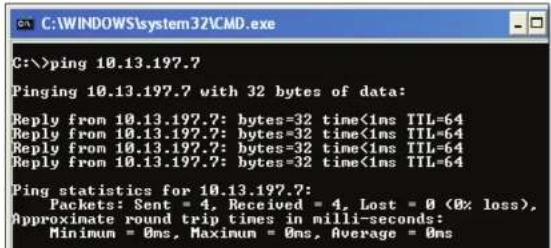
- Execute a ping command by entering "ping" followed by a space and the new IP address at the command prompt. For example: ping 10.13.197.7
You must ping the IPCP 505 in order for the IP address change to take place. The response should show the new IP address, as shown in figure 13.
Configuring the IPCP for Network Use Via a Web Browser
The default web pages that are proloaded on the IPCP 505 are compatible with popular web browsers such as Microsoft Internet Explorer (version 5.5 or higher) or Mozilla Firefox (version 1.0 or higher). However, the IPCP and the PC must both be part of the same subnet before they can communicate. You must change the IP address of the PC to one that is on the same subnet as the default IP address of the IPCP 505 (192.168.254.254).
NOTES:
- This method requires connecting the IPCP to the LAN port of the PC using a crossover network cable (see page 13 for cabling details).
-
Make a note of the host TCP/IP configuration of the PC before changing its IP address and make sure the PC and IPCP are on the same subnet.
-
Temporarily change the IP address of the host PC. See Setting up the PC for IP communication with an IPCP 505 on page 23 for step-by-step instructions.
-
Obtain a valid IP address for the controller from your network administrator.
- Launch the web browser on the connected PC (for which you set up the network configuration earlier), and enter http://192.168.254.254/ in the address box. The default web page of the IPCP 505 is displayed.
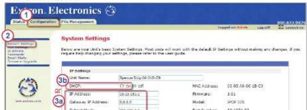
- Select the Configuration tab (see figure 15, ①).
- Select System Settings from the menu on the left of the screen (see figure 15, ②). A web page appears.
Configuring the IPCP for Network Use Via SIS Commands and Telnet
The IPCP and the PC must both be part of the same subnet before they can communicate. You must change the IP address of the PC to one that is on the same subnet as the default IP address of the IPCP 505 (192.168.254.254).
NOTES:
- This method requires connecting the IPCP to the LAN port of the PC using a crossover network cable (see page 13 for cabling details).
-
Make a note of the host TCP/IP configuration of the PC before changing its IP address and make sure the PC and IPCP are on the same subnet.
-
Temporarily change the IP address of the host PC (see Setting up the PC for IP Communication With an IPCP 505 [the next topic in this section] on page 23 for instructions).
-
Start Telnet on the PC:
a. Click the Start menu and select Run. The Run dialog box appears, as shown at right.
b. Type telnet, a space, and the default IP address (192.168.254.254) into the Open field, and click OK.
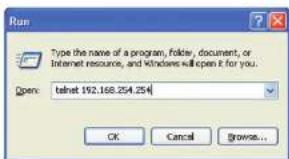
Figure 16. Step 2b: The Run Dialog Box
-
Set the IPCP to the new IP address by doing one of the following.
-
Enter SIS command Esc X14 CI←, where X14 is the new IP address (see the SIS Programming and Control section starting on page 50) to set the IP address.
-
Enter SIS command 1DH ← to enable DHCP.
-
After changing the IP address of the IPCP controller, change the TCP/IP settings of your PC back to their original configuration.
-
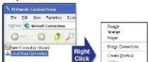
Open the Network Connections page as follows:
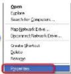
- Locate and right-click on My Network Places on the Windows 2000, Windows XP (or higher version) desktop, then click on Properties.


or
- Click on the Start menu, click on Settings (if needed), click on Control Panel to open the Control Panel window, and double-click on Network and Dial-up Connections (Windows 2000), Network Connections (Windows XP, shown below),
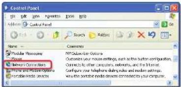
or Network and Sharing Center (Windows 7, shown below).

Network and Sharing
Center
- Access the properties dialog box.
- For Windows XP, right-click on Local Area Connection. then select Properties.
- Select Internet Protocol (TCP/IP) and click on the Properties button, as shown in figure 17 below for Windows XP (left) and Windows 7 (right). If Internet Protocol (TCP/IP) is not on the list, it must be added (installed). See the Microsoft Windows user manual or the Windows online help system for information on how to install the TCP/IP protocol.
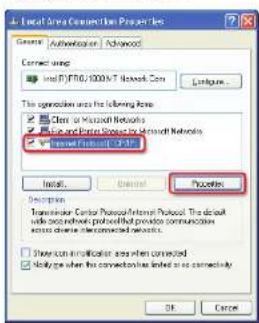
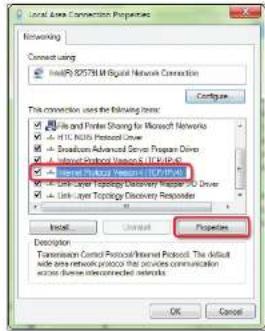
Figure 17. Selecting Internet Protocol (TCP/IP) For the LAN Connection
- Write down the PC's current IP address and subnet mask below. If your PC is set to "Obtain an IP address automatically," make a note of that, instead. You will need to restore these settings to the PC later.
IP address:

- Change the IP address of the PC so it can communicate with the IPOP, and change the IP settings of the controller.
a. Click the Use the following IP address button (see figure 18, ⑱).
b. Enter the following values, as shown in the following pictures for Windows XP (left) and Windows 7 (right) (see ①b):
IP address: 192.168.254.253
Subnet mask: 255.255.0.0
Default gateway: blank or 0.0.0.0
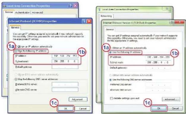
Figure 18. Step 5: Changing the IP Address of the PC
c. Click the OK button to save the changes and exit the network setup (see 1c). Reboot the PC, if required, for the changes to become effective.
- Plug one end of a CAT5 Ethernet crossover cable into the LAN connector on the IPCP (see page 13 for RJ-45 LAN connector wirinal). Plug the other end of the Ethernet
Global Configurator Software for Windows®
The included Global Configurator (GC) program for Windows offers the best, most complete way to configure and customize the controller. GC provides the ability to generate a web browser-based GlobalViewer (GV) application and web pages for each IP Link-based device (IPCP 505, IP Link control processor, System 5 IP, MLC 226 IP, MLC 104 IP Plus, or other Extron device) on a network. Once an IPCP 505 is configured, its GlobalViewer web pages allow the user to manage, monitor, and control the IPCP and the devices connected to it. Other setup options include using SIS commands and the factory-embedded web pages, but many setup features are available only via Global Configurator. GC includes some functions found on the embedded web pages of the controller and many additional features that are available only through the software.
Downloading the Software and Getting Started
Global Configurator software updates and a large variety of device drivers can be downloaded at no charge from the Extron website (www.extron.com). When you locate the desired software or driver package, follow the on-screen directions to download and install it.
NOTE: Ethernet, serial, and infrared (IR) device drivers (for controlling projectors, VCRs, DVD players, and so forth) are available on the Extron website...
• As individual device driver files
• As an IP Link driver package.
If an IR driver does not already exist for an IR-controlled device in your system, you can download the optional IR Learner. It is a free software utility that makes it possible to capture infrared codes from a handheld IR remote control and create custom drivers for operating the corresponding IR-controlled device.
NOTE: Do not change the directory or the name of the directory where the software files are installed by default.
Read the Global Configurator Help file for details and step-by-step procedures on how to start a GC project and perform basic setup tasks for an IPCP. The help file contains instructions on how to set the IP address, gateway IP address, subnet mask, mail
Using Global Configurator: Helpful Tips
Resources and Notes
- The IPCP 505 Setup Guide is shipped with the unit, and it covers how to install the software and lists other available resources (software, drivers, instructions). It includes a quick reference to the front and rear panel features, and covers basic hardware installation and how to set the IP address of the unit using the ARP command.
- The Global Configurator Help file provides information on settings and how to use the Global Configurator program, itself. This help file, included with the software, covers basic setup steps and includes examples of how to use the basic tabs in GC and step by step instructions for typical configuration tasks.
- See Front Panel Features on page 9 and Rear Panel Features and Connections on page 11 in the "Hardware Features and Installation" section of this guide for features and settings for the ports you will configure in GC.
- If you will configure the IPCP at the installation site, Extron recommends using the driver subscription function within Global Configurator to download drivers for all manufacturer and device types before you go out into the field.
- The Global Configurator project file (*.gc2 or *.gcz) contains configuration settings and it can be saved to a directory or folder for backup or for installation on another IPCP 505 controller. Saving a configuration is recommended before you perform a firmware upgrade.
- Global Configurator 3 is capable of loading all GC2 project files from GC version 2.0.3.3 and up. GCZ files can be opened by clicking File >Open, by clicking the toolbar icon, or by double-clicking on the GCZ file. GC2 and GCC files must be imported, however.
- The IPCP can be set up to allow configuration access only to administrators to prevent other users from making changes to settings, events, and controls. If an administrator password is set for the controller, non-administrator users can select inputs, adjust volume, and trigger some other device commands from the GlobalViewer Control pages but are prevented from making any other changes using GlobalViewer web pages.
- IP addresses, subnet mask, and e-mail addresses follow standard naming and numbering protocol. The network administrator provides the IP addresses and subnet mask to be used with this controller.
A Brief Guide to Tabs in Global Configurator
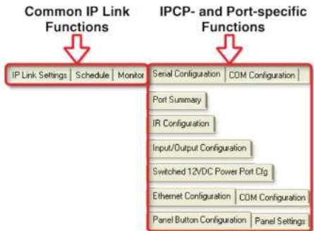
In the upper right side of the GC window are several tabs that divide the program into groups of functions you can view and configure. The left three, IP Link Settings, Schedule, and Monitor, are displayed for all IP Link-enabled products. Tabs to the right of those three vary in quantity, type, and layout, depending on the product and ports being configured. The following figures show tabs that may be available when you configure an IPCP 505.
flowchart
graph TD
    A["Common IP Link Functions"] --> B["IP Link Settings"]
    A --> C["Schedule"]
    A --> D["Monitor"]
    E["IPCp- and Port-specific Functions"] --> F["Serial Configuration"]
    E --> G["COM Configuration"]
    F --> H["Port Summary"]
    F --> I["IR Configuration"]
    F --> J["Input/Output Configuration"]
    F --> K["Switched 12VDC Power Port Cfg"]
    F --> L["Ethernet Configuration"]
    F --> M["COM Configuration"]
    F --> N["Panel Button Configuration"]
    F --> O["Panel Settings"]
Figure 19. Tabs That May Be Available in Global Configurator
To learn about the functions available on each of these tabs, see the Global Configurator Help file. In the contents pane on the left, click on Reference Information, click Global Configurator Window, then click on the name of the tab you want to know more about.
Advanced Configuration
Printing a Wiring Block Diagram or a GUI Configuration Report
Once you have configured a system using Global Configurator, you can generate and print a simple block diagram of what products to wire to which of the ports on the IPCP 505. The diagram includes model names and the type of communication (IR or RS-232) configured for each port. For more detailed information, in the Global Configurator Help file, read about the File menu within the "Referonco Information" section.
NOTE: This procedure requires Microsoft Word software (for a block diagram) or an internet browser application (for a GUI configuration report). The installer or user must provide that software. They are not Extron products.
Procedure overview:
- In Global Configurator, click on the File drop-down menu and select Print and then Wiring Diagrams/GUI Configuration Report.
- In the Print Wiring Diagrams/GUI Configuration Report window, select the devices to include in the diagram.
- Click the Print Wiring Diagrams button or the Print GUI Report button. GC processes the information about the selected device(s), generates a document containing the wiring diagram or report, and opens that document in Word (for the diagram) or in a browser window (for the GUI report).
To see an example of a wiring diagram, click here to open the Attachments area to the left of this page, then double-click on the name of the attached PDF file. The file opens in a now window. - Print the diagram(s) and, if desired, save the file(s). Exit Word or the browser.
- Close the Global Configurator Print Wiring Diagrams/GUI Configuration Report window.
Updating Firmware
If the need arises, you can replace the firmware of the IPCP without opening the unit or changing firmware chips. See the Firmware Updates section starting on page 78 for instructions on how to update the firmware for the controller.
NOTE: Save the existing GC configuration project before replacing the firmware.
Advanced Serial Port Control
If serial setup configurations are required, the following options provide more advanced methods for serial configuration within the IPCP:
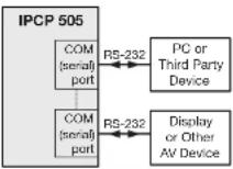
- Serial pass-through (or redirect mode) (page 32) — to pass a control signal in one serial port on the IPCP and out through another serial port on the same IPCP
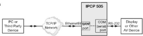
- Direct port access (page 32) — to pass a control signal through a Telnet connection on the IPCP to an AV device connected to an IPCP serial port
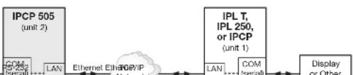
- Serial bridging (page 33) — to pass a control signal into a serial port on an originating IPCP (or IPL) through a network and out a specified serial port of a destination IPCP (or IPL) to a connected AV device
Serial Pass-through (redirect)
Direct Port Access
flowchart
graph LR
    A["PC or Third Party Device"] <--> B["TCP/IP Network"]
    B <--> C["EthernetE"]
    C --> D["IPCP 505"]
    D --> E["COM Israel port"]
    E --> F["RS-232"]
    F --> G["Display or Other AV Device"]
Serial Bridging
Serial pass-through (redirect mode)
Serial pass-through allows serial commands from a controller to "pass through" an IPCP 505 on route to an AV device. Any serial port on an IPCP can be configured as a pass-through connection to another serial port on the same device. For example, an RS-232 control device connected to the COM1 port on an IPCP 505 could control a projector connected to the COM2 port. COM1 passes through (redirects) the serial signal to COM2 in that example.
Serial pass-through is enabled or disabled through the COM Configuration tab within Global Configurator, as shown below and as described in the GC help file.
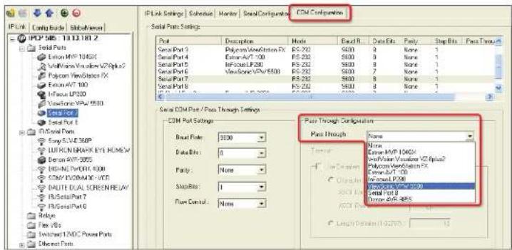
Figure 21. A Global Configurator Screen Showing Serial Pass-Through Configuration
Advanced users can use the pass-through SIS command as well (see the Simple Instruction Set CD commands on page 59 for detailed command descriptions).
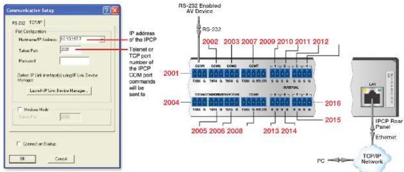
Direct port access (ports 2001 through 2016)
To initiate direct port access using Extron DataViewer software:
- Connect the IPCP 505 to a network.
- If necessary, use GC (see the help file for details), the Port Settings embedded web page (see page 40), or SIS commands (see page 58) to set serial port parameters (baud rate, parity, stop bits) for the IPCP 505 COM port to be used.
- Launch the DataViewer program.
- Click File > Connect to open the Communication Setup dialog box.
- Click the TCP/IP tab.
- Complete the fields with the IP address of the IPCP 505 and the TCP/IP port number (2001, 2002, 2003,...) of the COM port (on that same IPCP unit) that will be used, as shown below.
NOTE: A password is not required for direct port access.
Hardware connection
To set up the hardware for serial bridging:
- Verify that the protocol (baud rate, data bits, stop bits, parity) is identical for both serial ports that will be "bridged" (one port on each IPCP or IPL unit).
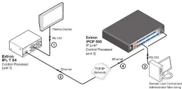
- For unit 1 (the remote IPCP or IPL device), connect a serial cable to an AV device such as a display or projector (see figure 23, ①).
- Connect that same remote IPCP or IPL (unit 1) to the LAN (see ②).
flowchart
graph TD
    A["Extron IPL T S4 Control Processor (unit 1)"] -->|①| B["Plasma Display"]
    B -->|②| C["TCP/IP Network"]
    C -->|③| D["Extron IPCP 505 IP Link® Control Processor (unit 2)"]
    D -->|④| E["Remote User Control and Administrator Monitoring"]
    C -->|Ethernet| B
    D -->|Ethernet| C
    style A fill:#f9f,stroke:#333
    style D fill:#ccf,stroke:#333
Figure 23. Connections for Serial Bridging
- For unit 2 (the local IPCP or IPL device), make a serial connection to the PC or controller that is to control the remote AV device (see ③).
- Connect the local IPCP or IPL device (unit 2) to the same network (see ④).
You are now ready to configure unit 2 (the local IPCP or IPL device) for serial bridging mode.
Panel 1.0.1.2.3.4.5.6.7.8.9.10.11.12.13.14.15.16.17.18.19.20.21.22.23.24.25.26.27.28.29.30.31.32.33.34.35.36.37.38.39.40.41.42.43.44.45.46.47.48.49.50.51.52.53.54.55.56.57.58.59.60.61.62.63.64.65.66.67.68.69.70.71.72.73.74.75.76.77.78.79.80.81.82.83.84.85.86.87.88.89.90.91.92.93.94.95.96.97.98.99.100
- Access the web server port setting screen by clicking the Configuration tab, then the Port Settings link on the left side of the window (see figure 24, ①). The Port Settings page appears, as shown in figure 24.
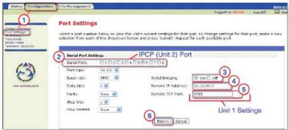
Figure 24. Port Settings Internal Web Page for Unit 2
- Choose the serial port (on the local IPCP 505, unit 2) that you wish to communicate through (see figure 24, ③).
- For serial bridging, click the On radio button to activate bridging mode (see ④).
- In the Remote IP Address field, type in the IP address of unit 1 (the remote device) (see ③).
- In the Remote TCP Port field, type in the number of the serial port number on unit 1 for this virtual connection (see ⑥).
- For an IPCP 505, choose a port number from 2001 (COM1) - 2016 (IR/serial port 8), as noted on page 32 in the direct port access section of this guide.
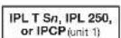
- For an IPL 250 or IPL T S Series control processor, choose from 2001 (COM1) - 2006 (COM6), based on the available COM ports. See the diagram below (figure 25).

Saving and Uploading the Configuration
This is not an advanced configuration function, but when you finish creating the configuration in Global Configurator, you must save the GC project and upload the configuration to one or more IPCP 505 units (see the Global Configurator Help file for instructions).
Controlling an IPCP 505
You can control the IPCP and devices connected to it by using a shared network and one or more of the following tools:
• The factory-embedded web pages within the IPCP
- The GlobalViewer (GV) web pages that are created when you upload the GC configuration to the IPCP
- A TouchLink touchpanel with a customized graphical user interface (GUI), provided that the TouchLink is included in the IPCP 505 configuration
Embedded Web Pages
The IPCP 505 features an embedded web server, which includes factory-set web pages. These pages can be replaced with user-designed files, but the default web pages provide many basic features for monitoring, configuring, and controlling the unit via a web browser. This section provides an overview of these web pages, which provide some of the features of the configuration program.
To access the embedded web pages,
- Launch a web browser (Internet Explorer, Mozilla Firefox) on the connected PC, enter the IP address of the IPCP in the address field, and press the
key.
NOTE: After GlobalViewer web pages have been uploaded to the IPCP, the GV web pages open by default (instead of the factory-set web pages) if you enter just the IP address (such as 10.13.197.7 or http://10.13.197.7) of the IPCP unit. To view the factory-set web pages on a GV-enabled IPCP unit, add /nortxe_index.html after the IP address before pressing
Status
The Status web page provides only settings information. Changes must be made via the Configuration web page, the Global Configurator software, or SIS programming. Personnel who have user access can view the Status page but do not have access to configuration pages.
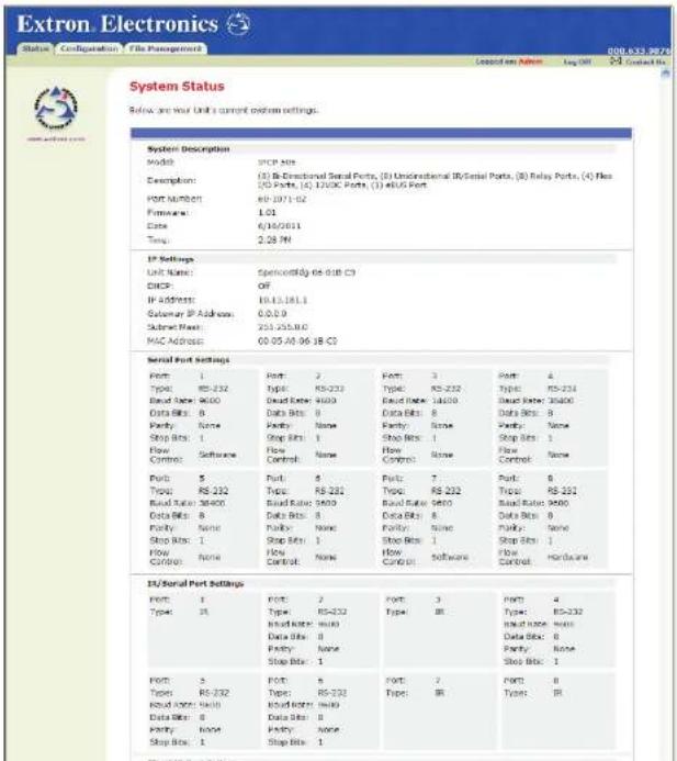
System Status
The System Status page provides information about the IPCP 505 model, part number, firmware version, port and IP settings, as shown in the following example. This information is useful when troubleshooting.
Configuration
There are six Configuration web pages, which only administrators can access:
- System Settings
- Port Settings
- IR Drivers
- Passwords
- Email Alerts
- Firmware Upgrade
System Settings
This page is for IP and date/time setting changes.
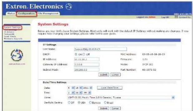
Figure 27. A System Settings Embedded Web Page
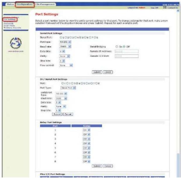
Port Settings
This page allows limited changes to serial (COM) port, IR/serial port, and flex I/O port settings, and to the on/off status of each relay port. It also permits control and grouping of the switched 12 VDC power output ports.
IR Drivers
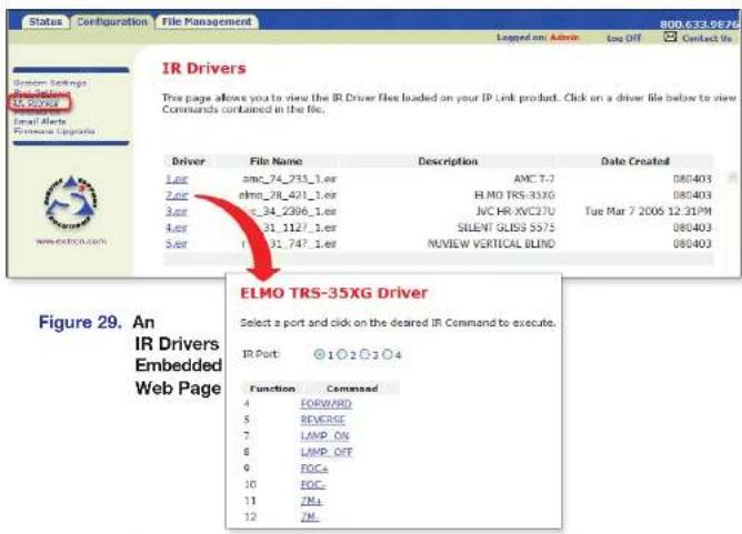
Once the IPCP 505 is configured and IR drivers have been uploaded to the unit and linked to specific IR ports, you can view a list of the uploaded drivers using this page. Click on the name of the driver file to switch to a view of the commands loaded for that driver. Clicking on a port and then a command name makes the IPCP send that command out its linked IR port to the connected device.
Passwords
In the Passwords page you can change the administrator and/or user passwords.

Email Alerts
In this page you can specify the IP address and domain name of the web server, set up SMTP verification credentials, and specify the addresses of e-mail alert recipients and which e-mail file they will be sent.
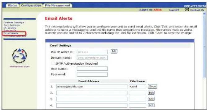
Figure 31. An Email Alerts Embedded Web Page
Firmware Upgrade
Through this page you can locate and load new firmware to the unit.

File Management
This web page allows you to sort by file type (see the Filter by File Extension drop-down box). Personnel with administrator access can view these pages and make changes. Those with user-level privileges are not able to see this page. For an explanation of file types see File Types: a Key to Extron-specific File Names on page 77.
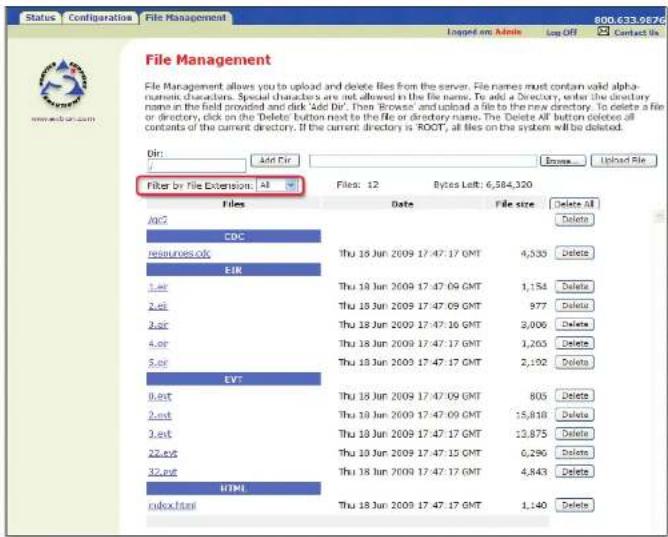
Figure 33. A Typical File Management Page with Filtering by File Extension
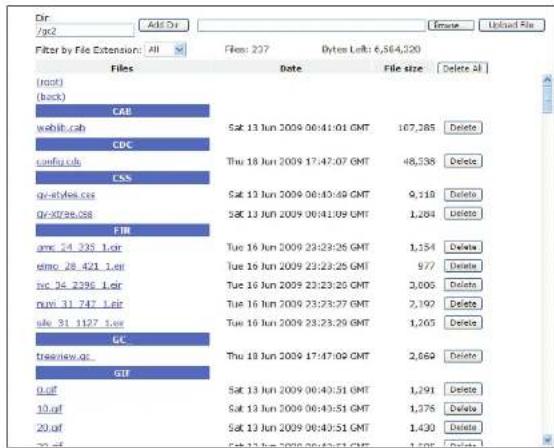
Figure 34. A File Management Page For a Subfolder
GlobalViewer Web Pages
Once an IPCP 505 (or other IP Link-based device) is configured using Global Configurator, GC generates the web browser-based GlobalViewer (GV) application for that unit. Once uploaded to the IPCP, the GlobalViewer web pages allow the user to manage, monitor, and control the IPCP and the devices connected to it.
NOTE: To work with GlobalViewer web pages, you must use Microsoft Internet Explorer version 6.0 or higher with ActiveX enabled.
The following figures are examples of IPCP 505 GlobalViewer pages.
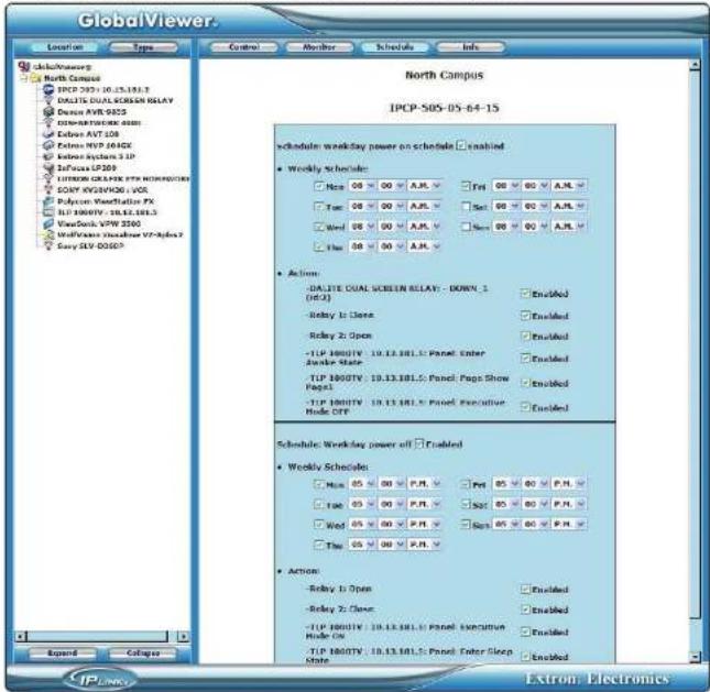
Figure 35. A GlobalViewer Schedule Page
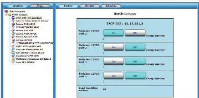
Figure 37. An IPCP-specific GV Control Page for Switched Power Output Ports
If a device has been set up with control drivers, click on the name of the system or on the name of the device on the left side of the GlobeViewer window to open a Control page that shows the available commands for all of the controlled devices or for that one specific device. The following figure shows an example.
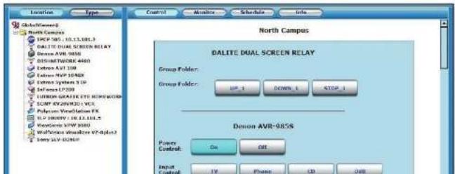
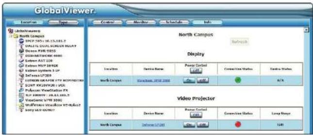
Figure 39. A GlobalViewer Info Page
Controlling the IPCP 505 with a Touchpanel
After both devices are configured, the IPCP 505 can be controlled with an optional Extron TLP touchpanel.
- Set up the graphical user interface (GUI) for each touchpanel by using the GUI Configurator software. See the GUI Configurator Help file for details.
- Connect the touchpanel(s) to the same network that the IPCP 505 uses.
- While configuring the IPOP using Global Configurator, add each TLP to the Touchpanel ports. Connect to the TLPs and upload the GUI layout for each panel (see the Global Configurator Help file for the procedure).

Customizing the IPCP Control Web Pages
Extron offers web page templates that can be customized using standard HTML editing tools or third-party software such as Microsoft® FrontPage or Adobe® Dreamweaver® to provide a different interface to the user while still using GlobalViewer functions. An experienced web developer can add images, modify text, and change background colors to create a look and feel that reflects your brand or specific requirements of the user. For example, a university with dozens of devices and rooms to control may wish to create customized web pages with the school colors and logo of the university. End users can control the system using these customized pages instead of the standard GV pages.
Alternatively, Extron can create a customized GUI for you to upload to each IPCP 505 in the system. End users can view the web pages of this customized GUI while administrators and installers still have access to the factory-set web pages and the standard GV web pages in addition to the customized ones.
For a small, one-time fee, Extron will turn the following items into files ready to upload to the unit:
- Your GlobalViewer project file containing system configuration details
- Your choice of available color schemes
- Your choice of labels for panel buttons
• A company or institution logo
Visit the Extron website (http://www.extron.com/product/customgui.aspx) or contact an Extron customer support representative for more information on this service and on available template options.
Troubleshooting
Turn on the input devices (DVD players, VCRs, PCs, and other sources), output devices (display screens, projectors), the IPCP 505, and the PC and touchpanel. Touch a configured button on the touchpanel or (via PC) click a control button on the IPCP embedded Control web pages.
If an input or output AV device cannot be remotely controlled (does not respond as expected), check the following:
Power Connections
• Ensure that all devices are plugged in.
- Make sure that each device is receiving power. The IPCP front panel Power LED lights if the device is receiving power.
Data Connections
- Check the cabling connections and make adjustments as needed. The Link LEDs on the IPCP and on the touchpanel or PC should be lit solid green if a network connection is detected. If these LEDs are not lit, either the cable is faulty or not plugged in, or the wrong type of cable is being used (see page 13 in "Hardware Features and Installation").
-
Try to "ping" the unit by entering ping 192.168.254.254 at the command prompt, or use the IP or web address provided to you by your system administrator. If you get no response:
-
Make sure your unit is using the appropriate subnet mask (check with your system administrator).
-
Make sure your PC and network do not have a software firewall program that might block the IP address of the IPCP unit.
-
If contact is established with the unit, but the IPCP web pages cannot be accessed by your web browser, verify (via an Internet network options or preferences menu) that your web browser is configured for direct network connection and is not set up to use a proxy server.
SIS Programming and Control
This section covers the following topics:
• Host-to-IPCP Communications
• Commands and Responses
The IPCP 505 can be remotely controlled via a host computer, touchpanel, or other device (such as a control system) attached to a shared network.
The IPCP must be configured before use. As shipped, the controller/processor cannot control any other devices or interact with a touchpanel until it has been configured. Set up the IPCP or control it by using Simple Instruction Set (SIS) commands or Global Configurator software (version 3.2 or higher) via an Ethernet LAN connection. See page 13 in the "Hardware Features and Installation" section for pin assignments and protocol. For information on the software and the embedded web pages, see Software-based Configuration and Control starting on page 18 and see the help files for the software.
IPCP 505 LAN port defaults:
• IP address: 192.168.254.254
• Gateway IP address: 0.0.0.0
- Subnet mask: 255.255.0.0
DHCP: off
Host-to-IPCP Communications
SIS commands consist of one or more characters per field. No special characters are required to begin or end a command sequence. When the IPCP determines that a
Additional messages may be sent by the IPCP in response to changes made through the touchpanel and when scripts are executed during scheduled events.
Password Information
The “←Password:” prompt requires a password (administrator level or user level) followed by a carriage return. The prompt is repeated if the correct password is not entered.
If the correct password is entered, the unit responds with "Login Administrator", "Login Administrator", or "Login User", depending on the password entered. If passwords are the same for both administrator and user, the unit defaults to administrator privileges.
Error Responses
When the IPCP 505 receives a valid SIS command, it executes the command and sends a response to the host device. If the IPCP is unable to execute the command because the command is invalid or it contains invalid parameters, it returns an error response to the host.
The error response codes and their descriptions are as follows:
E10 - Invalid command
E12 – Invalid port number
E13 – Invalid value (the number is out of range/too large) or parameter
E14 - Not valid for this configuration
E22 - Busy
E24 - Privilege violation
E25 - Device is not present
E26 - Maximum number of connections has been exceeded
E27 - Invalid event number
E28 - Bad filename or file not found
E31 - Attempt to break port pass-through when not set (A user or software attempted to disable the port redirect feature when it was not already set or active.)
Error Response References
The following superscripted numbers are used within the command descriptions on the following pages to identify commands that may respond as shown:
The ASCII to hexadecimal (HEX) conversion table shown here is for use with the
command/response tables: The command/response tables Space → list valid ASCII command codes, the corresponding URL (uniform resource locator) encoded (for web browsers) command codes, the responses of the IPCP to the host, and a description of the command's function or the results of executing the command.
| ASCII to Hx | Conversion Table | Exc. 1B | CR | 8D | LF | OA | |||||||||
| 20 | 1 | 21 | " | 22 | # | 23 | 5 | 24 | % | 25 & | 26 | 27 | |||
| (28) | 29 | " | 2A | + | 28 | 2C | - | 2D | . | 2E | / | 2F | |||
| 0 | 30 | 1 | 31 | 2 | 32 | 3 | 33 | 4 | 34 | 5 | 35 | 6 | 36 | 7 | 37 |
| 8 | 38 | 9 | 39 | 3A | 3B | < | 3C | =3D | > | 3E | ? | 3F | |||
| @ | 40 | A | 41 | B | 42 | C | 43 | D | 44 | E | 45 | F | 46 | G | 47 |
| H | 48 | 49 | J | 4A | K | 4B | L | 4C | M | 4D | N | 4E | O | 4F | |
| P | 50 | Q | 51 | R | 52 | S | 53 | T | 54 | U | 55 | V | 56 | W | 57 |
| X | 58 | Y | 59 | Z | 5A | 1 | 5B | \ | 5C | 1 | 5D | ^ | 5E | _ | 5F |
| 60 | a | 61 | b | 62 | c | 63 | d | 64 | e | 65 | f | 66 | g | 67 | |
| h | 68 | 69 | J | 6A | k | 6B | I | 6C | m | 6D | n | 6E | o | 6F | |
| p | 70 | q | 71 | f | 72 | s | 73 | t | 74 | u | 75 | v | 76 | w | 77 |
| x | 78 | y | 79 | z | 7A | (7B | I | 7C) | 7D | -7E | DELLF | ||||
Figure 41. ASCII to Hex Conversion Table
Entering SIS Commands: Helpful Tips
- Upper and lower case characters may be used interchangeably in the command field unless otherwise specified.
- Commands may be sent back-to-back without spaces (for example, 2!65V1Z).
Numbers can be entered as 1, 2, or 3 digits, for example, 8V = 08V = 008V . -
There are a few differences in how to enter the commands depending on whether you are using Telnet or a web browser.
-
When using these commands through a web browser, the URL reference is used to shorten the examples. "URL" refers to the full URL of the control interface and web page reference including all path information (such as http://192.168.100.10/myform.htm).
- To send any of the commands using a web browser you must prefix them with the full URL followed by ?cmd=.
- For control via a web browser, all non-alphanumeric characters must be represented as the hexadecimal equivalent, %xx, where xx represents the two-character hex byte. A comma ( ), for example, would be represented as %2C. Characters such as %, 1, and the space character () must be encoded as hex bytes, or they will be misinterpreted by the IPCP. For example, the ASCII command +V must be encoded as %2BV for web browser use.
In other method, Data = data that will be directed to a specified port and must be hex encoded if non-alphanumeric.
NOTE: If you make adjustments, it takes up to 1 minute 40 seconds (100 seconds) for the data in the IPCP RAM to be saved to flash memory. Do not remove power during that period.
Symbol Definitions
← = CR/LF (carriage returnline feed) (hex OD DA)
← = Carriage return (no line feed, hex CD) (for URL-encoded commands, use the pipe character, ||, instead)
• = Space character
| = Pipe (vertical bar) character
* = Asterisk character (which is a command character, not a variable)
Esc = Escape key (hex 1B) (for URL-encoded commands, use W instead of Esc)
X1 = Specific port number or relay number (01-99) Serial ports: IR/serial ports:
01 = COM1 port 09 = IR/serial port 1
02 = COM2 port 10 = IR/serial port 2
03 = COM3 port 11 = IR/serial port 3
04 = COM4 port 12 = IR/serial port 4
05 = COM5 port 13 = IR/serial port 5
06 = COM6 port 14 = IR/serial port 8
07 = COM7 port 15 = IR/serial port 7
08 = COM8 port 16 = IR/serial port 8
Relay ports: Flex I/O ports:
01 = Relay port 1 01 = I/O port 1
02 = Relay port 2 02 = I/O port 2
03 = Relay port 3 03 = I/O port 3
04 = Relay port 4 04 = I/O port 4
05 = Relay port 5
06 = Relay port 6
07 = Relay port 7
08 = Relay port 8
Switched power output ports:
01 = power port
02 = power port 2
X3 = Greenwich Mean Time (GMT) offset value (-12.00 to +14.00) represents the time difference in hours and minutes (+/-hh:mm) relative to Greenwich, England. The leading zero is optional. For example, 5:30 = 05:30. Do not use a plus (+) sign if the GMT offset is positive.
[X5] = On/off status 0 = off/disable 1 = on/enable
x11 = Version (typically listed to two decimal places; for example, x, xx)
X12 = IPCP 505 unit name. The name is a text string of up to 24 characters drawn from the alphabet (A-Z), digits (0-9), and minus sign/hyphen (-). No blank or space characters are permitted as part of a name. No distinction is made between upper and lower case. The first character must be a letter. The last character must not be a minus sign or hyphen.
X13 = Local date and time format Set format (MM/DD/YY-HH:MM:SS). Example: 01/18/05-10:54:00
Read formal (day of week, date month year HH:MM:SS). Example: Tue, 13 Jun 2011 18:19
X14 = IP address (xxx.xxx.xxx.xxx). Leading zero in each of the four fields are optional in setting values, and they are suppressed in returned values. IPCP 505 default address: 152.168.254.254.
X15 = E-mail domain name; for example, extron.com
X17 = Time in tens of milliseconds to wait until the first response character is received via a serial port before terminating the current working operation
X21 = Parameter (WL or #D) to set either the Length of
message to receive or the byte count (for 1) or
# = a single ASCII character expressed in
decimal form (for D). The parameter is case-sensitive: you must use
capital "D" or capital "L"
Byte count # can be from 0 to 32767,
The ASCII decimal i can be from 0 to 00255.
default = 03000CL
Examples:
A 3-byte length = 3L.
A deflator of ASCIF OA = 10D.
The response from the unit includes leading zeros.
X22 = Verbose/lagged response mode status:
| NOTE: In verbose/response mode, the device (the IPCP) responds with more information than it usually would. For example, the IPL can send out a notice of a change in some setting without receiving a query via your PC. That change could have been a result of an internal process (a script execution), a selection made using a touchcase or keypad, a change made using GV or a web page, or input from a connected sensor or switch. |
| That is an example of a verbose (wordy) relationship between the controller and a connected device. Verbose mode creates more network traffic than usual, which can slow down network performance. |
0 = clear, default for Telnet connections
1 = verbose mode is on [enabled];
2 = Verbese mode is on, tagged responses are not for queries it-target responses are enabled
3 = verbose mode is on [enabled] and tagged
responses are enabled and sent for queries
| VerboseResponses | TaggedResponses | |
| Receive unsolicitedresponses(messages)for all options | Receive taggedresponses toread/viewrequests |
X23 = Priority status for receiving timeouts:
0 = use send data string command
parameters (i) = Delta
1 = use configure receive timeout command
parameters
X25 = Baud rate: 300, 600, 1200, 1800, 2400, 3600.
4800, 7200, 9600 (default), 14400, 16200,
- 36450, 37500, 6110200
[X2θ] = Parity (only the first letter is needed);
O = odd
E = even
N = none (defect)
M = mark
X27 = Data bits: 7, 8 (default = 8)
x28 = Stop bits: 1, 2 (default = 1)
X29 = Serial port type:
0 RS-232 (the only serial protocol supported)
by COMT-COMS ports, and the default for
COM7-COM8
2-BS-485
X30 = Flow control (only the first letter is needed);
H hardware
S - software
X31 = Data pacing (time between bytes) in milliseconds
(0000 - 1000), 0000 (5 ms) is the default.
X33 = Password(minimum length = 4 characters,
maximum length = 12 characters]. Passwords
are case sensitive. No special characters
are allowed. Use alphanumeric characters Disallowed characters are shown below.
| Character Hex Dec | |||
| Space 20.32 | |||
| " | Quotation marks | 22.34 | |
| < | "I less than" symbol | 3C | 60 |
| > | "Greater than" symbol | 3E.62 | |
| $ | "Found (hash mark) | 23.35 | |
| % | Percent | 25 | 37 |
| { | Left curly brace | 7B | 123 |
| | | Right curly brace | 7D | 125 |
| Vertical bar / pipe | 7C | 124 | |
X34 = Daylight saving time (DST) is a region-specific 1 hour offset that begins in spring and ends in fall. 0 = off/ignore (default)
1 = USA on - DST begins on the second Sunday of March at 2 AM and ends at 2 AM on the first Sunday of November. For example, time in California is GMT -8:00 from March to November and GMT -7:00 from November to March. However, DST should be turned off in Hawaii, American Samoa, Guam, Puerto Rico, the Virgin Islands, the eastern time zone portion of the state of Indiana, and the state of Arizona (excluding the Navajo Nation).
2 = Europe on – begins on the last Sunday in March, ends on the last Sunday in October. DST should be turned off for Iceland. 3 = Brazil on
X35 Event number: 0 - 99 This is valid only while events are running.
×36 = Event buffer
0 = receive 1 = user (absolute, unified) 2 = user (relative, data) 3 = NVRAM
X37 = Event buffer offset: 0 - [max. buffer size]
X38 = Event data buffer size (only the first letter is needed) b = bit B = byte (8 bits) S = short (16 bits) L = long (32 bits)
NOTE: This parameter is case sensitive.
x39 = Event data to write
X40 = Flex I/O mode
0 digital input
2 = digital input with +5 VDC pull-up
3 = digital output with +5 VDC pull-up
4 = analog input
= analog input with +5 VDC pull-up
6 = digital input with adjusted thresholds
requires x55 and x56 thresholds)
7 = digital input with adjusted thresholds with 15
VDC pull-up (requires x55 and x56 thresholds)
X47 = Name (for CR commands) or numeral (1 - 939, for SM commands) of the e-mail file to be sent
NOTE: E-mail files must have a file extension of .em1. The first line of the file is the subject, the rest is the body of the e-mail.
X49 = Default name: a combination of the model name and the last 3 pairs of the MAC address of the unit (for example, IPCP-505-03-69-B0)
X50 = Redirection status: 0 = no redirection 1 - 16 = redirect serial port communication from the specified port (1 = COM1, 2 = COM2, 3 = COM3...8 = COM8; 9 = IR/portal port, 1... 16 = IR/portal port B) to allow a serial pass-through mode (see Serial pass-through (redirect mode) on page 32 in the "Software-based Configuration and Control" section).
X52 = Security level of the connection:
0 = not logged in
1 = USCf
12 = administrator The response includes leading zeros.
X53 = Timeout period in tens of milliseconds for serial data pass-through mode, after which event data can be inserted into the transmit buffer and the serial port is released to another source. (Default 10 - 100 ms, range 1 - 32767.) The response includes leading zeros.
X54 = ASCII digit(s) representing the numeric value of the data element read from the event buffer (Leading zero are suppressed.)
X55 = Upper signal transition threshold (detection of a "1") for digital inputs: 0-01095 (0-25.3 VDC) 328 = default = 2 VDC
X56 = Lower signal transition threshold (detection of a "0") for digital inputs; 0-04095 (0-25.3 VDC) 164 = default = 1 VDC.
NOTE: The lower threshold (X56) must be smaller than the upper threshold (X55).
X63 = Pulse time in 20 ms increments. If this parameter is missing or = 0, then pulse length = default = 25 - 500 ms. 1 = 20 ms (minimum pulse time) to 65535 = 1310700 ms (maximum pulse time).
X59 = IP connection timeout period specified in 10-second steps (1 - 65000, default = 30 = 300 seconds). If no data is received during the specified period, the Ethernet connection closes. Responses are returned with leading zeros.
X70 = The number (0 - 65535) to insert into an email message if an email tie has an embedded server side include "<1->#echo var = "VCR" ->>" (the End CR← command with no parameters) The numeral is a 16-bit number to be employed as the user defines. This is an optional parameter. Use 0 as a placeholder if the optional X47 variable is used but X70 is not needed. Maximum = 65535.
X73 = An e-mail account username of up to 31 characters. Do not use commas. This parameter is optional during setup and is used for SMTP authentication.
X74 = An email account password (for SMTP authentication) of up to 31 characters. Do not use commas. This parameter is optional during setup. If a password is set, the response is not the actual password characters but asterisks (****).
X85 = Switched output power load status; 0 = ck (total power draw <40 watts) 1 = at limit (total power draw is 40-44 watts) 2 = fault/overload (total power draw >44 watts)
X86 = Switched output power use. total power drawn from all power output ports = ran, in tenths of watts
X07 = Switched output power group: 0 = no group 1 = group 1 2 = group 2
X210 = IR/serial port configuration type 0 = IR port (default, 0 - 5 VDC) 1 = RS-232 port (±5 VDC)
NOTE: For commands and examples of computer or device responses mentioned in this guide, the character "0" is used for the number zero and "0" represents the capital letter "o".
Command/Response Table for SIS Commands
| Command ASCII (Telnet) (host to IPCP) URL Encoded (web) (host to IPCP) Response (IPCP to host) Additional description | ||||||||
| Serial port configuration and use These commands apply to any port that uses RS-232 communication: both 1-way (output) and 2-way (bilinear) RS-232 communication. Sand data string Esc X1 X17 X20 X21 RS ← X2 X1 VX1 %2A X17 %2A X20 %2A X21 RS | X2 response from command← | ||||||||
| NOTE: *X17 *X20 *X21 is optional. X17 may be omitted only if X20 is also missing. If these (three variables are not specified, the default values are used. For this command, X17 and X20 must both a) equal zero or b) be nonzero, or c) both be omitted. | ||||||||
| NOTE: For web encoding for X2, convert non-alphanumeric characters to hex numbers. A space (max = 20) is encoded as %20. A plus sign (max = 2B) is encoded as %2B. | ||||||||
| Example: Esc 05*4*7*3L RS ←<data> W05%2A4%2A7%2A3L RS |<data> response from command← | ||||||||
| NOTE: The data string i X2 in the RS command is limited to 200 bytes. | ||||||||
| NOTE: Use the ASCII to decimal table below to convert the delimiter character for X21 when using a delimiter (D). |
Command/Response Table for SIS Commands (continued)
| Command ASCII (Telnet) | (host to IPCP) | URL Encoded (web)(host to IPCP) | Response(IPCP to host) | Additional description |
| Configure serial port parameters24 | Esc X1 X28 X28 X27 X28 CP ← | X1 = serial port numberSerial ports: IR/serial ports:01 = COM1 port 09 = IR/serial port 102 = COM2 port 10 = IR/serial port 203 = COM3 port 11 = IR/serial port 304 = COM4 port 12 = IR/serial port 405 = COM5 port 13 = IR/serial port 506 = COM6 port 14 = IR/serial port 607 = COM7 port 15 = IR/serial port 708 = COM8 port 16 = IR/serial port 8 | ||
| W X1%2A X25%2C X26%2C X27%2C X28 CP |CpnX1+Ccp X25 X26 X27 X28← | ||||
| Example: | Esc 2*9600, N, 6, 1CP ← | X25 = baud rate (300-115200 baud, default= 9600 baud).X26 = parity (0 - odd, E = even,N - none [default], M - mark, S - space). | ||
| W2%2A9600%2CN%2C8%2C1CP |Cpn02+Ccp9600, N, 6, 1← | X27 = data bits: 7, 8 (default = 8).X28 = stop bits: 1, 2 (default = 1).Set port 2 for 9600 baud, no parity,8 data bits, and 1 stop bit. | |||
| View serial port parametersExample | Esc X1 CP ← | W X1 CP | X25 | X26 X27 X28← | |
| Esc 2CP ← | 9600, N, 0, 1← | |||
| Configure mode24 | Esc X1^X29 CY ← | W X1%2A X29 CY | | CpnX1+Cty X29← | X29 = serial port type:0 = RS-232 the only serial protocolsupported by COM1 COM6 ports, and thedefault for COM7 COM8:1 = RS-4322 = RS-485. |
| View mode | Esc X1 CY ← | W X1 CY | | X26← | |
| Configure flow control | Esc X1^X30 X31 CF ← | X30 = flow control(H = hardware, S = software, N = none).X31 = data pacing in milliseconds (0000 - 1000). | ||
| W X1%2A X30%2C X31 CF | | CpnX1+Cf 1 X30 X31← | |||
| View flow control24 | Esc X1 CF ← | W X1 CF | | X30 X31← | |
| Configure receive timeout24 | Esc X1^X17 X20 X23 X21 CE ← | Set the time to wait (X17) = waiting time intens of ms until receipt of the first responsecharacter before terminating the receiveoperation, X20 = waiting time in tens of msbetween characters before terminaling) andpriority status.(X28) = default, use send data string | ||
| W X1%2A X17 %2A X20 %2A X23 %2A X21 CF |CpnX1 Cc(X17 X20 X23 X21← | ||||
| Configure serial pass-through mode24 | Esc X1 X50 X63 X21 CD← | X1 = specific port number (01 - 08)X50 = Redirection status:0 = no redirection1 - 8 = redirect serial port communication from the corresponding COM port(see Serial pass-through (redirect mode) on page 32 in the "Software-based Configuration and Control" section).X53 = Timeout period in lens of milliseconds (1 - 32767) for data pass-through mode.X21 = Parameter (uL or 10) to set either the Length of message to receive or the Delimator value. # = byte count (for L) or # = a single ASCII character expressed in decimal form (for D). The parameter is case sensitive. Byte count # can be from 0 to 32767, default = 0.The ASCII decimal # can be from 0 to 00255, default 00000L. | ||
| W X1 %2A X50 %2A X53 %2A X21 CD |Cpn X1 C0000 X63 X21← | ||||
| Terminate serial pass through mode2 | Esc X1 +0 CD← | W X1 %2A 0 CD | | Cpn X1 Ccd 00000 , 00000 , 00000L← | End serial pass through. |
| View serial pass through mode | Esc X1 CD← | W X1 CD | | X50 X53 X21← | |
| Ethernet port configuration and use | ||||
| Set current Ethernet connection timeout period4 | Esc 0* X69 TC← | W0%2A X69 TC | | Pti 0* X69← | X69 = IP timeout period spocied in 10 second stops (1 - 65000, default = 38 = 300 seconds). If no data is received during the specified period, the Ethernet connection closes. Responses include leading zeros. |
| The current port timeout period applies to the currently open Telnet session only. When you start another Telnet session, it uses the default global port timeout period. | ||||
| View current connection timeout period | Esc 0TC← | W0TC | X69 | ← | |
| Set global Ethernet connection timeout period4 | Esc 1* X69 TO← | W1 %2A X69 TC | | Pti 1* X69← | |
| View global connection timeout period | Esc 1TC← | W1TC | X69 | ← | |
| Command ASCII (Telnet) | URL Encoded (web)(host to IPCP) | Response(IPCP to host) | Additional description | |
| Host to IPCP | ||||
| IR/Serial port use | ||||
| The following variables are used for these IR/serial port commands: | X50= IR playback function number (1-137), of a specific function or command set contained within the file. | |||
| K1 port number | ||||
| 09 = IR/serial port 1 10 = IR/serial port 2 | IR function numbers 0 and 127 or higher can return information only. | |||
| 11 = IR/serial port 3 12 = IR/serial port 4 | 0 - return all cats | 132 - remote 137 - user file name | ||
| 13 = IR/serial port 5 14 = IR/serial port 6 | 129 - manufacturer | 133 - creation date (is descriptive name the user/ | ||
| 15 = IR/serial port 7 16 = IR/serial port 8 | 130 - mode | 134 - comments instaler gave the file. | ||
| Port numbers are two ASCII characters (2 bytes). For example, port 1 is represented as 01. | 131 = class | |||
| X57 = the IR file number (0-39), as in files 1, ein, 2, eir, 3, eir, and so on, stored in the controller. Each .eir file contains commands for a specific device. | X59= IR playback mode | X210= IR/serial port configuration type | ||
| 0 - play one | 0 = IR port (default, 0 = VOC) | |||
| 1 - play continuously | 1 = RS-232 port (HS VOC). | |||
| 2 - stop. | ||||
| View IR/serial port configuration | Esc X1 IC← | WX1 IC | X210← | ||
| Send an IR command ^16 | Esc X1 X57 X58 X59 IR← | WX1%2C X57%2C X59%2C X59 IR| | Send an IR command via IR/serial output port number X1 | |
| IrsX1 X57 X58 X59← | The response includes leading zeros. | |||
| Get IR command into ^3,29 | Esc X57 X58 IR← | WX57%2C X58 IR | | (descriptive text)← | The response to this command is the name/ description (such as Power On, Power Off, Enter, Play, Stop, RRB, Menu) of the specific command you ask about. |
| Example: | Esc 3,1TR← | W3%2C 1IR| | POWER← | Command/function 1 in file 3.eir is the Power command. |
| Example: | Esc 3,2IR← | W3%2C 2IR| | E13← | Command/function 2 in file 3.eir is not defined or does not exist, so the controller returns E13, the invalid value error number. |
| NOTE: An IR driver must be loaded into the IPCP before IR command information can be read. | ||||
| Command ASCII (Telnet) | (host to IPCP) | URL Encoded (web)(host to IPCP) | Response(IPCP to host) | Additional description |
| Flex I/O port useFor flex I/O commands, 40 Flex I/O mode:0 = digital input 4 = analog input1 = digital output 5 = analog input with +5 VDC pull-up2 = digital input with +5 VDC pull-up 6 = digital input with adjusted thresholds require 55 and 56 thresholds3 = digital output with +5 VDC pull-up 7 = digital input with adjusted thresholds with +5 VDC pull-up (requires 55 and 56 thresholds)NOTES: • Modes 6 and 40 = 6 or 7 allow you to specify the digital input signal voltage range.• The default signal range for digital input modes 0 and 2 is 1-2 VDC. | 55 = Upper signal transition threshold (detection of a "1") for digital inputs:0-04095 (0-25.3 VDC)328 - default < 2 VDC 56 = Lower signal transition threshold (detection of a "0") for digital inputs:0-04095 (0-25.3 VDC)164 = default < 1 VDC.NOTE: The lower threshold ( 56 ) must be smaller than the upper threshold ( 55 ). 63 = Pulse time in 20 ms increments.If the parameter is missing or = 0, then pulse length = default = 25 = 500 ms,1 = 20 ms (minimum pulse time) to 65535 = 1316700 ms (maximum pulse time). | |||
| 43 = Flex I/O port status:0 = off1 = onn (0 4895), analog port voltage increments of about 0.006 V per step for analog in modes, based on 12 bit A (to D conversion over a range of 0 to about 24 V) | ||||
| Set I/O mode 0-5 | 1 · 40 | 1 × 2A × 40%5B Cpn | 1 · Iom 40 | Set flex I/O port 1 to function as a digital input, digital output, or analog input with or without using the +5 VDC pull-up resistor. |
| Set I/O mode 8-7 | 1 · 40 × 55 × 55 | 1 × 2A × 40%2A × 55%2A × 58%5B | ||
| View I/O mode 0-5 | 1 | 1 × 5B | 1 · Iom 40, 55, 56 | |
| View I/O mode 6-7 | 1 | 1 × 5B | 40 | |
| Pulse I/O state ^14 | 1 × 3 × 63 | 1 × 2A × 3 × 2A × 53%5D Cpn | 1 · Sio 43 | |
| Toggle I/O state ^4 | 1 × 2 | 1 × 2A × 2 × 5D Cpn | 1 · Sio 43 | |
| Set I/O state on ^4 | 1 × 1 | 1 × 2A × 1 × 5D Cpn | 1 · Sio | |
| Set I/O state of ^4 | 1 × 0 | 1 × 2A × 0 × 5D Cpn | 1 · Sio | |
| View I/O state | 1 | 1 × 5D | 43 | |
| Relay port use | ||||
| Pulse relay | 1 × 3 × 630 | 1 × 2A × 3 × 2A × 630 Cpn | 1 · R1 × 5 | 1 = Relay port number:01.88 = Relay port 1.8 |
| Turn relay off (incon) | 57140 | 57141.70 | 57142.70 | 57143.70 |
| Switched 12 VDC power output port use | ||||
| Set a switched power port on or off | EscP X1*X3 DCPP← | WP X1*2A[X3] DCPP | | DcppP X1*X3←X1 | = switched power port number (1-4):X5 = port status: 0 = off, 1 = on. |
| Example: | EscP1*0 DCPP← | WP1 *2A @ DCPP | | DcppP1*0← | Example: turn 12 VDC output port 1 off(no power output). |
| View switched power port on/off status | EscP X1 DCPP← | WP X1 DCPP | X5← | ||
| View the load condition status of the switched power ports | EscS DCPP← | WSDCPP | X85← X85 | = Switched output power load status:0 = ok (total power draw <40 watts),1 = at lms (total power draw is 40-44 watts),2 = fault/download (total power draw >44 watts). | |
| View power use status | Esc ADCPP← | WADCPP | X86← X88 | = Switched output power use:total power drawn from all power output ports = nm, in tenths of watts. | |
| Example: | Esc ADCPP← | WADCPP | | 114← | Example: the power drawn from all four switched power output ports is 11.4 watts. |
| Assign a group number to a power port ipower output grouping | Esc GX1*X87 DCPP← | X87 | = Switched output power group:0 - no group1 - group 12 - group 2. | |
| WG X1*2A[X87] DCPP | | DcppG X1*X87← | |||
| View power output grouping | Esc GX1 DCPP← | WG X1 DCPP | X87← | ||
Firmware version, part number, and information requests
| NOTE: Responses to commands differ depending on which, if any, verbose response mode the IPCP is in. See the CV command [Esc] [X22] CV←, page 68) under IP setup commands later in the table. | |||
| NOTE: In a 00 query response, an asterisk (*) after the version number indicates the version that is currently used. A question mark (? or ???) indicates that the factory default firmware is the only firmware loaded in the IPCP. A casei (*) indicates the version of firmware that should be running, but, since a mode 1 reset was performed, the factory default firmware version is loaded and running instead. An explanation point (t) indicates that the firmware is corrupted. | |||
| Query firmware version number | 0 or 10 0 or 10 | X11← | Show the firmware version [X11] of the IPCP to two decimal places. This query yields the number of the currently running version of the user-updatable firmware. |
| or Ver01*X11← | |||
| Example: | 10 10 1.01 | or Ver01*1.01 | |
| Query verbose firmware version information | |||
Command/Response Table for SIS Commands (continued)
| Command ASCII (Telnet) | (host to IPCP) | URL Encoded (web)(host to IPCP) | Response(IPCP to host) | Additional description |
| Query firmware version | 10 10 | X11←or Ver01*X11← | This command shows the currently-running firmware version X11 of the IPCP to two decimal places. | |
| Example: | 10 10 | 1.01← | ||
| Query bootstrap firmware version | 20 20 | X11←or Ver02*X11← | The bootstrap firmware is not user-replaceable, but you may need this information during troubleshooting. | |
| Example: | 20 20 | 0.08← | ||
| Query factory firmware version | 30 30 | X11kernel version-model description-date time of upload←or Ver03*X11kernel version-model description-date time of upload← | ||
| Example: | 30 30 | 1.00(1.81-IPCP Series | Wed, 17 Jan 2003 00:00:00 GMT)←In this example the factory firmware version is 1.00 and the IP Link kernel version is 1.81 for the IPCP, dated 17 January 2003. | |
| NOTE: Factory installed firmware is different from the bootstrap firmware, but it is also not user replaceable. This firmware was installed at the factory; it is the version the controller reverts to after a mode 1 reset (see page 16 in the "Hardware Features and Installation" section). | ||||
| Query updated firmware version | 40 40 | X11(kernel version-model description-date time of upload←or Ver04*X11kernel version-model description-date time of upload← | Use this command to find out which version of the firmware, if any, was uploaded into the controller after it left the factory. | |
| Example: | 40 40 | 1.01*(1.01-IPCP Series | -Fri, 11 Feb 2011 03:56:14 GMT)←In this example the current firmware version is 1.01, the IP Link kernel version is 1.81, and the last firmware upload was on February 11, 2011. | |
| NOTE: Responses to commands differ depending on which, if any verbose response mode the IPCP is in. See the CV command [EscX22] CV←, page 66 under IP setup commands later in this table. | ||||
| Request the IPCP part number | N | N | 68-1071-02←or Pno68-1071-02← | Show the IPCP part number. |
| Request the mode name | 11 11 | IPCP*505←or Inf01*IPCP*505← | IPCP 505. | |
| Request the mode description | 21 21 (8) B1-Directional Serial Ports, (8) Unidirectional IR/Serial Ports, (8) Relay Ports, (4) Flex I/O Ports, (4) 12VDC Ports, (4) USB Port← | |||
| Request: system memory usage | 31 3I | # Bytes used out of # of Kbytes←or Inf03*# Bytes used out of # of Kbytes← | Show amount of memory used and totalavailable memory for system operations. | |
| Example: | 31 3I | Inf03*12000 Bytes Used out of 1024 KBytes← | ||
| Request user memory usage | 41 4I | # Bytes used out of # of KBytes←or Inf04*# Bytes used out of # of KBytes← | Show amount of user memory used and totalavailable user memory. The maximum usermemory on an IPCP is about 9/5 MB. | |
| Example: | 41 4I | 4096 Bytes Used out of 1001488 KBytes← | ||
| IP setup commands | ||||
| Set the unit name ^TM | Esc X12 CN← | W X12 CN | | Ipn×X12← | Change the IPCP unit name to one of yourchoosing X12, user-defined unit name, suchas "AuditoriumIPCPI", "Fim316-AVcenter", or"exoc-boardroom-ctrl". |
| NOTE: The name consists of up to 24 alphanumeric characters (and the minus sign).The first character must be a letter, the last character cannot be a minus sign(hyphen); Spaces may not be used. Either case (upper, lower) is OK. | ||||
| Set unit name to factory default ^TM | Esc •CN← | W %20 CN | | Ipn×X49←X49 | The name the IPCP was shippedwith: IPCP-505-00-00-00, a combination ofthe model name and the last 3 pairs of hexnumbers in the MAC address of the controller(for example, IPCP-505-00-10-A0). |
| Read the unit name | Esc CN← | VICN | X12← | or X49← | |
| Set data/time ^TM | Esc X13 CT← | W X13 CT | | Ipt×X13←X13 | = Local date and time format.The set format is MW/DO/YY-NH:MM:SS.Example: 01/31/11-10:54:00. |
| Read data/time | Esc CT← | WCT | | X13← | The Read format is day of week, DOmonth year HH:MM:SS.Damore Wed, 15 Jun 2011 11:57:17. |
| Set GMT offset ^TM | Esc X3CZ← | W X3 CZ | Ipz | X3← | Set the Greenwich Mean Time (GMT): offsetvalue X3 for the location of the IFCPinstallation. GMT offset (-12.00 to +14.00)represents the time difference in hours andminutes (+/-nh mm) relative to Greenwich,England. The leading zero is optional. Forexample, 5:30 - 05:30. Do not use a |
| Set daylight saving time ^a | EscX34CX← | WX34CX| | IpxX34← | |
| X34 = Daylight saving time (DST) is a region-specific 1-hour offset that begins in spring and ends in fall.0 = off/ignore (default).1 = USA on - Starting in 2007, DST begins on the second Sunday of March at 2 AM and ends at 2 AM on the first Sunday of November. For example, time in California is GMT 8:00 from March to November and GMT 7:00 from November to March. However, DST should be turned off in Hawaii, American Samoa, Guam, Puerto Rico, the Virgin Islands, the eastern lime zone portion of the state of Indiana, and the state of Arizona (excluding the Navajo Nation).2 = Europe on - Begins on the last Sunday in March, ends on the last Sunday in October. DST should be turned off for Ireland.3 = Brazil on. | ||||
| Read daylight saving time | EscCX← | WCX | X34 | ← | |
| Set DHCP on ^b | Esc1DH← | W1DH | | Idh1← | |
| Set DHCP off ^c | Esc∅DH← | W0DH | | Idh0← | |
| NOTE: Changing DHCP from on to off also resets the IP address to the factory default (192.168.254.254). | ||||
| View DHCP on/off mode | EscDH← | WDH | | X5← | X5 = 0 (off, default) or 1 (on). |
| Set IP address ^d | EscX14CT← | WX14CI | Ipi· | X14← X14 | = IP address (xxx.xxx.xxx.xxx). Leading zeros in each of the four fields are optional in setting values. |
| Road IP address | EscCI← | WC1 | X14 | ← | Loading zeros in each of the four fields are suppressed in returned values. |
| Read hardware address (MAC) | EscCH← | WCH | X18 | ←or Iph×X18← | X18 = hardware (WAC) address(00-05-A6-xx-XX-XX). |
| Set subnot mask ^e | EscX19CS← | WX19CS | | Ips×X19← X19 | = subnet mask (xxx.xxx.xxx.xxx). Syntax is the same as for IP addresses. Leading zeros are optional in setting values. |
| Road subnot mask | EscCS← | WCS | X19← | Loading zeros are suppressed. | |
| Set gateway IP address ^f | EscX14CG← | WX14CG | | Ipg×X14← | |
| Read gateway IP address | EscCG← | WCG | X14← | ||
| Get a connection listing | EscCC← | WCC | | (number of connections)←orIcc(number of connections)← | Display the number of currently active IP client connections. |
| Example: | EscCC← | WCC | | 002← | Example: This shows two client connections. |
Command/Response Table for SIS Commands (continued)
| Response (IPCP to host) | ||
| Additional description | ||
| 0 | Verbose Responses | Tagged Responses |
| Receive unsolitcd messages for all actions initiated via any source touchpanel, port input, internal web page changes, or commands) instead of only for SIS commands | Receive lagged responses to read/view requests (Responses to SIS commands are always tagged. Turing lagged responses on adds tags to the response to SIS read requests.) | |
| 0 | ||
| 1 | ✓ | |
| 2 | ✓ | |
| 3 | ✓ | ✓ |
Command/Response Table for SIS Commands (continued)
| Command ASCII (Telnet) | (host to IPCP) | URL Encoded (web)(host to IPCP) | Response(IPCP to host) | Additional description |
| Password and security settings | ||||
| Read the security level of the connection | Esc CK← | VICK | X52 | ←or Pv1X52← | ForX520 – not logged in11 = user12 = administrator.The response includes leading zeros. |
| Set administrator password^26 | EscX33 CA← | W X33 CA | | Ipa•X41← | Set the administrator access password X33 4 to 12 alphanumeric characters). The password is case sensitive. Special characters (spaces, symbols) are not allowed.X41= Password to display on screen (response to password query).X41 is 4 astersks (***). If a password has been assigned, or it is an empty field{ }If a password has not been assigned. |
| Clear administrator password^24 | Esc • C← | W%20 CA ← | Ipa•← | Clearremove all passwords (administrator and user). |
| NOTE: If the administrator password is cleared, the user password is also cleared. | ||||
| Read administrator password^24 | Esc CA← | VCA | X41← | ||
| Set user password^14,26 | EscX33 CU← | W X33 CU | | Ipu•X41← | Set the user password X33 is 4 to 12 alphanumeric characters). The password is case sensitive. Special characters (spaces, symbols) are not allowed. X41= Password that is displayed on screen. |
| NOTE: A user password cannot be assigned if an administrator password does not exist. Also. If the administrator password is cleared, the user password is also cleared. | ||||
| Clear user password^26 | Esc • CU← | W%20CU | | Ipu•← | This clears the user password only. |
| Read user password^26 | Esc CU← | VICU | X41← | ||
| Remapping port designationsFor security reasons the network administrator may wish to assign new/different port numbers to the Telnet, web browser, and direct access ports of the controller or to disable one or more ports. Typically Telnet uses port 23, web access is via port 80 (HTTP), and direct access is via port 2001.ATTENTION: Do not set two or more ports to the same port number. Setting two ports to the same number could cause networking conflicts and will also result in an E13 (invalid parameter) error. | ||||
| NOTE: If you remap a port, you must set the port number to 1024 or higher, unless you reset the port to the default number or disable the port by setting it to 0. | ||||
| Set the Telnet port map ^26 | Esc port#MT← | Vport#MT | | Pmt port#←↓ | Select a number (port#) for the port that will not conflict with any other ports. |
| Reset the Telnet port map ^1 | Esc 23WT← | W23MT | | Pmt 00023←↓ | This resets the Telnet port to port 23. |
| Disable the Telnet port map ^4 | Esc ONIT← | W8WT | | Pmt 00000←↓ | Setting the port number to 0 disables the port. |
| Read the Telnet port map | Esc MT← | WNT | | port#←↓ | It set to the default port number, the response is 00023. |
| Set the web (HTTP) port. map ^24 | Esc port#MH← | Vport#MH | | Pmh port#←↓ | |
| Reset the web (HTTP) port map ^25 | Esc 80WH← | W80WH | | Pmh 00000←↓ | This resets the web port to port 80. |
| Disable the web (HTTP) port ^24 | Esc ONIH← | W80IH | | Pmh 00000←↓ | |
| Read the web (HTTP) port map | Esc MH← | WNH | | port#←↓ | |
| Set the initial port number for the direct access port map ^4 | Esc port#MD← | Vport#MD | | Pmd port#←↓ | This command sets the initial (lowest) port number for the range numbers assigned to the series ports for direct port access (see page 12 for port location and page 32 for more on direct access). By default the PCP direct access port numbers start at 2001 (for COWT) and go up to 2016 (for IR/serial port 8). |
| Reset the direct access port map ^24 | Esc 2001MD← | W2001MD | | Pmd 02001←↓ | This resets the initial direct access port to port 2001. |
| Disable the direct access ports ^24 | Esc ONID← | WOND | | Pmd 00000←↓ | |
| Read the direct access port map | Esc MD← | WND | | port#←↓ | |
| Directory commands | ||||
| Change or create a directory | Esc path/directory/ CJ←W path%2F directory %2F CpDir•path/directory;← | The directory name must be composed of alphanumeric characters and may include the minus sign (hyphen, -) and the colon (-). The first character must be a letter. Case does not matter. No blank or space characters are permitted in the name.Include the full path, not just the name of the directory. Nonalphanumeric characters in the path (such as /) must be encoded to hex characters for use with a web browser. | ||
| NOTE: A directory does not fully exist until a file has been copied into that path. Also, the IPCP operates differently from PC operating systems: files stored in and directories created in the IPCP may have the same names. | ||||
| Example: | Esc majordirectory/subdirectory/next-level/ CJ←Wmajordirectory %2F subdirectory %2F next-level %2F CJ |Dir•majordirectory/subdirectory/next-level/ ← | |||
| Example: | Esc custompages/HTMLfiles/ CJ←Wcustompages %2F HTML files %2F CJ |Dir•custompages/HTMLfiles/← | This example creates a subdirectory for storing custom-made HTML files from the user. The directory that was just created is called HTML files. | ||
| Example: | Esc oak/CJ← W oak %2F CJ |Dir• oak← | |||
| Change back to the root directory | Esc/CJ← W%2F CJ |Dir•← | |||
| Co up one directory level | Esc.. CJ← W%2E%2E CJ |Dir•path/directory/← | |||
| View the current directory | Esc CJ← WCJ |path/directory/← | |||
| NOTE: The current directory is octomined on a por-connection basis. At the beginning of each IP connection/session, the current directory is selected as the root directory. | ||||
| File handling commands | ||||
| Erase the user supplied web page and file(%) | Esc filename EH← W filename EH | Del• filename← | |||
| List files from the current directory | EsoDF← | WDF | | [↑filename 1]•[day, date time of upload]GMT•[file size 1 in bytes]←[↑filename 2]•[day, date time of upload]GMT•[file size 2 in bytes]←[↑filename 3]•[day, date time of upload]GMT•[file size 3 in bytes]←...[↑filename n]•[day, date time of upload]GMT•[file size n in bytes]←[space remaining (to 7-digits)]•Bytes Left←← | Retrieve a list of files stored in the controller.Each line of the response lists a different file name and its corresponding file size. The last line of the response indicates how much available file space there is. |
| When working with the IPCP 505 embedded web pages, the response visible in a JavaScript" server-side include (inserted between | tags into HTML source code) follows this structure: | |||
| Example (via Telnet or HyperTerminal): | EsoDF← | WDF | | var file-new Array();file[1]="[filename 1],[day, date time1 of upload] GMT,[file size 1 in bytes]";file[2]="[filename 2],[day, date time2 of upload] GMT,[file size 2 in bytes]";file[3]="[filename 3],[day, date time3 of upload] GMT,[file size 3 in bytes]";...file[n]="[filename n],[day, date time2 of upload] GMT,[file size n in bytes]";file[n+1]="[space remaining (to 7-digits)],Bytes Left";←← | 4.evT Tue, 01 Mar 2011 02:03:07 GMT 42233←1.eml Tue, 01 Mar 2011 02:03:34 GMT 200←2.eml Tue, 01 Mar 2011 02:03:34 GMT 300←2.eir Tue, 01 Mar 2011 02:03:34 GMT 1683←6.evT Tue, 01 Mar 2011 02:03:36 GMT 17956←4.eir Tue, 01 Mar 2011 02:03:47 GMT 6849←IPCpmain.sc Tue, 01 Mar 2011 02:03:52 GMT 8515←0.evT Tue, 01 Mar 2011 02:03:56 GMT 34413←99.eml Tuo, 01 Mar 2011 02:04:19 GMT 178←buttons.xml Tue, 01 Mar 2011 02:04:19 GMT 17214←IPCp.cfg Wed, 16 Mar 2011 21:34:45 GMT 7100← |
Command/Response Table for SIS Commands (continued)
| Command ASCII (Telnet) | URL Encoded (web) | Response | Additional description |
| (host to IPCP) | (host to IPCP) | (IPCP to host) | |
| File streaming commands | |||
| NOTE: File streaming commands should be used by advanced programmers only. | |||
| Load a file to user flash memory via Telnet or RS-232 ^25 | |||
| Eco+ UF filesize, filename ←(raw, unprocessed data in a file of up to filesize) | |||
| Up1← | |||
| or: | |||
| Load file to user flash memory via Telnet or RS 232 and set specific time and date for the uploaded file ^26 | = 1-7 where 1 = Sunday. | ||
| Eco+ UF filesize* | = 1-12 where 1 = January. | ||
| ◆, filename←(raw, unprocessed data in a file of up to filesize) | = 1-31. | ||
| Up1← | = 0-23. | ||
| NOTES: If the IPCP has insufficient memory available to store the sent file, it responds with F1d←(failed) instead of with Up1←(uploaded).Firmware can be updated by using this command to upload an ____,s19 file to the IPCP. If the IPCP determines that the file is not intended for its model, the Up1←response is followed by a Fwm←(firmware mismatch) response. | |||
| Retrieve a file from user flash memory via Telnet or RS-232 ^26 | |||
| Ecofilename SF← | |||
| W filename SF| | {4 bytes of filesize, and then raw data from the file} | ||
| Load a file to user flash memory via port 80 if HTTP, web: | |||
| Sand a Post command on port 80 followed by the delimited data to be written to the file in flash memory. | |||
| Retrieve a file from user flash memory via port 80 (HTTP, web) | |||
| Sand a Page Get command on port 80 followed by WSF| | |||
| Example: http://192.168.254.254/mypage.html?cmd=WSF| | |||
| {data from the file mypage.html} | |||
| Web browser-specific commands | |||
| Road response from last URL command | EcoUB← | WUB | | (response from command)← |
Command/Response Table for SIS Commands (continued)
| Command ASCII (Telnet) | (host to IPCP) | URL Encoded (web)(host to IPCP) | Response(IPCP to host) | Additional description |
| E-mail commands | ||||
| Configure e-mail events (mailbox) ^24 | EscX45 X48 X47 CR←X45W X45%2C X46%2C X47 CR | IprX45 X48 X47← | = e-mail event number (1 - 64).X46 = e-mail recipient address (for example,JDoc@extron.com) for the person to whom messages will be sent. This address is limited to 31 characters.X47 = name of e-mail file to be sent (1.eml,2.eml, ... 64.eml)(first line of the file - the subject,the rest - the body of the e-mail).For e-mail event 5, send file 7.eml to jdoc@extron.com. | ||
| Example: | Esc 5, jdoe@extron.com, 7.eml CR←W5 %2C jdoe %40 extron %2E com %2G 7 %2E eml CR | Ipr 5, jdoe@extron.com, 7.eml← | |||
| Read e-mail event | EscX45 CR←W X45 CR | X46 | X47← | = o-mail event number (1 - 64). | |
| Send e-mail file specified in thee-mail event configuration ^24 | EscX45 SM←W X45 SM | Em1X45← X45 | |||
| Send a different e-mail file (one not configured for an e-mail event) orsend an e-mail file using a different e-mail address (one that has not been specified via theCR command during e-mail configurations) ^24 | EscX45 X43 X70 X47 SM←W X46%2C X45%2C X70%2C X47SM | Em1X45← | X46 = e-mail recipient address, limited to 240 characters.X70 = The number to insert into an e-mailmessage if a ____, em1 file has an embedodeservor side include "<1--#echo var="WCR| " -->" the Esc← command with noparameters). The numeral is a 16-bit numberto be employed as the user defines.This is an optional parameter. Use @ as aplaceholder for the optional X47 variable isused but X70 is not needed. | ||
| NOTE: If the X47 .oml is not found when the SM command is executed, the IPCP sends a default e-mail message. | X47 = xxx, where xxx = a number 1 - 999corresponding to the e-mail file name(xxxx.eml): if xxx = @ or no parameter isgiven, the unit sends the file that was set vathe CH command. | |||
| Sel e-mail server IP address and user domain name*4 | ||||
| Esc X14 X15 X73 X74 CM← | X14 = IP address (xxx, xxx, xxx, xxx),Loading zeros are optional in setting values;they are suppressed in returned values. | |||
| Start events ^4,7 | Esc1AE← | W1AE | | Ego← | Start all events. |
| Stop events ^2,22 | Esc0AE← | W0AE | | Est← | Stop running all events. |
| Query quantity of events running | EscAE← | WAE | | #####←or Enm ####← | The response is the quantity of currently running events, and it includes loading zeros. For example, if two events are running, the response is 00002←. |
| Reset (zap) commands and erase commands | ||||
| Erase the flash memory ^8 | EscZFFF← | WZFFF | | ZpT← | |
| Reset all device settings to factory defaults ^9 | EscZXXX← | WZXXX | | Zpx← | The "reset all settings" command does not affect IF settings or flash memory. |
| NOTES:• The ZXXX command does not reset any IP-related settings such as the IP address, subnet mask, and gateway IP address. It also does not affect user files stored in flash memory.• Contact Input ports are reset to open position, relays are set to open, receive timeout periods are reset to defaults, port redirection settings are cleared and ended. | ||||
| Reset all device settings and delete 1kes ^11 | EscZY← | WZY | | Zpy← | |
| NOTE: This command is intermediate between the ZXXX and ZOOQ commands. It is an absolute system reset excluding IP settings, IP address, subnet mask, gateway IP address, unit name, DHCP settings, port mapping. The allows you to maintain communication with the IPCP. Files, file directories, and passwords are erased by this command. This reset is recommended after you perform a firmware update. | ||||
| Absolute system reset ^12 (mode 5 reset) | EscZ000← | WZ000 | | Zpq← | Reset all settings/memones. The ZOOQ command resets everything (all settings, adjustments, the IP address, and subnet mask) to the factory default values. Files in flash memory are also erased by this command.The firmware version does not change. The IP address is reset to 192 168.254.254, the subnet mask is reset to 255.255.0.0. |
| NOTE: This command is identical to reset mode 5, discussed in Resetting the Unit starting on page 18 in the "Hardware Features and Installation" section. | ||||
Reference Information
This section of the guide includes the following reference items:
- Glossary
• File Types: a Key to Extron-specific File Names
Full product specifications are available via the IPCP 505 product page at
www.extron.com.
Glossary
10/100Base-T
Ethernet which uses unshielded twisted pair (UTP - CAT 5, CAT 5c, CAT 6) cable, where the amount of data transmitted between two points in a given amount of time is equal to either 10 Mbps or 100 Mbps.
ARP (Address Resolution Protocol)
A protocol which assigns an IP address to a device based on the MAC or physical machine address of the device.
Custom web page
Any file that can be loaded into an IPCP and served by the internal web server. The IPCP can be used for various web-based tasks. The web page provides a way to control the IPCP and other devices attached to it without use of the software, and with or without an accompanying event script. Any number and size of graphics can be used. If they are too large to fit in the nonvolatile memory of the IPCP, web pages can be created so that they can be served from another web server using Microsoft Internet Information Services (IIS).
DHCP (Dynamic Host Configuration Protocol)
A standardized communications protocol that enables network administrators to locally and automatically manage the assignment of IP addresses within the network of an organization.
Driver
A software package that controls the interface between the controller and peripheral devices.
MAC (Media Access Control) Address
A unique hardware number given to devices that connect to a network such as the Internet. When a computer or networking device (router, hub, interface, and the like) is connected to a LAN or the Internet, a table (see ARP) relates the IP address of the device to its corresponding physical (MAC) address on the LAN.
Ping
A utility/diagnostic tool that tests network connections. It is used to determine if the host has an operating connection and is able to exchange information with another host.
Port number
A preassigned address within a server that provides a direct route from the application to the transport layer or from the transport layer to the application of a TCP/IP system.
SSI (server side include)
A type of HTML instruction set that tells the IPCP (or some other web server) dynamically which material to include in the contents of a web page or e-mail. SSI files typically have a file extension of .shtml.
Static IP
An IP address that has been specifically (instead of dynamically—see DHCP) assigned to a device or system in a network configuration. This type of address requires manual configuration of the actual network device or system and can only be changed manually or by enabling DHCP.
Subnet — See subnetwork.
Subnet address
The portion of an IP address that is specifically identified by the subnet mask as the subnetwork.
Subnet mask
A 32-bit binary number (12 digit decimal number, xxx.xxx.xxx.xxx) used on subnets (smaller, local networks) to help routers determine which network traffic gets routed internally (within the subnetwork) to local computers and which network traffic goes out to the rest of the network or the Internet. It is an address mask used to identify the bits of an IP address that are used for the subnet address. Using a mask, the router does not need to examine all 32 bits, only those selected by the mask.
Subnetwork
A network that is part of a larger IP network and is identified by a subnet address. Networks can be segmented into subnetworks to provide a hierarchical, multilevel routing structure.
TCP (Transmission Control Protocol)
A connection-oriented protocol defined at the Transport layer of the OSI reference model. It provides reliable delivery of data.
TCP/IP (Transmission Control Protocol/Internet Protocol)
Verbose
A wordy way of speaking. For the IPCP and other IP-enabled products, verbose mode is a communication mode in which the device responds with more information than it usually would. For detailed information, see the verbose mode SIS commands on page 66 in the "SIS Programming and Control" section. Verbose mode is usually enabled for troubleshooting and disabled for daily use. Verbose mode creates more network traffic than usual and can slow down performance.
File Types: a Key to Extron-specific File Names
You must have a basic understanding of the types of files used by the controller in order to decide what (if anything) to do with them.
- __. cdc — These are compressed device configuration files created and used by Global Configurator.
ATTENTION: ____. cdc files should NOT be deleted.
- __.eir – These are IR driver files containing infrared commands. There is a separate .eir file for each device the IPCP controls via infrared communication. This is the type of file created during IR learning. Via Global Configurator, these files can be imported and associated with one of the IR ports on the controller.
- __. eml — E-mail template files have the . eml extension. These files are used to generate e-mail messages such as those regarding projector disconnection and excessive projector lamp hours. The first line of the file is the subject. The rest of the file contains the body of the e-mail. For the IPCP, these files are numerically named (1 through 64). For example, 1. eml, 2. eml, 3. eml,... 64. eml.
- __.evt — These are event files, the most important files for the functioning of the IPCP. Almost everything the IPCP does is coordinated by the scripts in the main event file, ∅.evt. The other event files perform device driver functions.
ATTENTION: Event files should NOT be deleted. They are necessary for the operation of the IPCP. Never delete the main event file (∅.evt).
- ____.gc2 or ____.gcz — These are configuration files that are used by
Firmware Updates
If the need arises, you can replace the IPCP main firmware without opening the unit or changing firmware chips. This section covers the following aspects of how to do that:
• Determining the Firmware Version — How to find the current firmware version
- Updating the Main Firmware — How to download and replace firmware
Determining the Firmware Version
There are several ways to check which version of firmware the controller is using:
• The IP Link Settings tab within Global Configurator (GC) software
• The System Status or the System Settings page of the IPCP embedded web pages
• The GlobalViewer web pages
- The response from the controller to an SIS command of 1Q (see page 62) or 0Q (see page 62)
Using the Global Configurator Software
- Via Ethernet, connect a PC (on which the Global Configurator program has been installed) to the IPCP.
- Start the Global Configurator (GC) program and open a project (see the Global Configurator Help file and see the Software-based Configuration and Control section of this guide on page 18 for details).
- In the window on the left side of the CC screen, click on the name of the IPCP for which you want to check the firmware version.
-
In the right side of the GC screen. click the IP Link Settings tab.
-
Type the IP address of the IPCP into the browser in the address field and log on to the internal web page (see the Software-based Configuration and Control section starting on page 18) or to the optional GlobalViewer web page stored in the IPCP (see the Global Configurator Help file for details).
NOTE: If GlobalViewer is installed in the IPCP, the GlobalViewer web pages appear by default.
- GlobalViewer web pages are supported by Internet Explorer, but not by other browsers. GlobalViewer features may not work properly when viewed via Navigator, Mozilla® Firefox®, Google Chrome™, or other browser programs.
-
To reach the factory default web pages on a controller that has been set up for GlobalViewer, type http://
-
In the factory default web pages:
- Select the Status tab. The firmware version is listed in the System Description area as shown at right.
Or
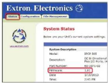
Figure 42. Locating the Current Firmware Version in the Status Embedded Web Page
- Select the System Settings page within the Configuration tab. The firmware version is listed in the IP Settings area as shown below.
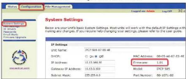
Updating the Main Firmware
Most firmware upgrade tools require the PC and the controller to both be connected to an Ethernet network. The instructions for each method of updating the IPCP firmware assume you have installed the appropriate software on your PC first.
NOTES:
- You should save the existing configuration to a file (see the Global Configurator Help file for instructions) before replacing the firmware. If the file is saved, the configuration can be restored to the IPCP later using Global Configurator.
- Check the Extron website (www.extron.com) for firmware-related documents, instructions, patch files, and new firmware files before loading new firmware into the controller. We recommend that you read the firmware release notes (available from www.extron.com) before beginning the firmware update.
Locating and Downloading the Firmware
- Visit the Extron website (www.extron.com) to find the latest firmware file for the IPCP.
- Download the executable installer file (.exe) from the website and run the installer program. The program automatically stores the firmware file on the PC in C:\Program Files\Extron\Firmware\IPCP_505\xx (a folder specific to that version).
- Write down the firmware filename and location for later use. The filename ends in .s19 such as IPL_T_Series_19_1364_50_vxx_xx.s19 where xx_xx is the version number (xx.xx) or IPLtvx.x.x.S19 where x.x.x indicates the version number.
NOTE: The firmware update file must have a filename extension of .s19. If the file does not have that extension, it will not work properly.
Updating Firmware via Extron IP Link File Manager Software
This is the recommended method for updating the firmware for an IPCP. It allows you to update one or several IPCPs at a time via an IP connection.
- Download the .\$19 firmware file.
- Start the IP Link File Manager (IPLFileManager) software on the connected PC. The main IP Link File Manager window appears on screen, as does the smaller Select Startup Mode window, shown in figure 45.
-
Click one of the Select Startup Mode buttons to choose how to add an IPCP to the firmware update list, click OK, and follow any on-screen instructions to add IPCPs.
-
Open Configuration File — Select this mode to open an existing configuration file.
- Import GC2.x Project
(recommended) — Select this mode to import a GC2.x project file and the names and IP addresses of the devices in it.
- Manually Add IP Link Device(s) — Select this mode to add IPCPs individually by IP address.
- Automatically Detect IP Link Device(s) — Select this mode to scan the network for IP Link devices, including IPOPs. You may need to provide administrator passwords for some units.
- Use Previous Setup — Choose this to show IP Link devices from your previous session of IP Link File Manager.
See the IP Link File Manager Help file if you need additional details on how to use any of those modes.
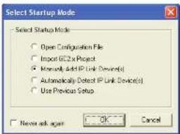
Figure 45. IP Link File Manager Select Startup Mode Window
-
Click on the Options menu and select Reset Device After Firmware Update. This option causes the controller to perform a ZY reset, which resets all device settings and deletes all files from the iPCP after the firmware is updated. See ZY command
-
Set the maximum number of firmware uploads that can take place at the same time (see figure 47, ①). The firmware files are uploaded to this many units at a time until all units listed in the Select Device list have received new files. The default is 5 uploads at a time, and the upper limit is the total number of units shown in the Select Device list.
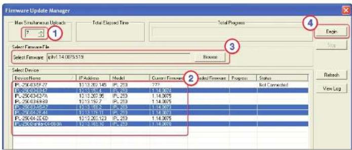
Figure 47. Steps 6 through 9: The Firmware Update Manager Window Prior to Uploading
-
In the Select Device list, select the devices for the firmware update (see figure 47, ②). Figure 47 shows an example of a system with IPL 250 units, but the process is identical for the IPCP.
-
-click on the name(s) of the unit(s) to select (or deselect) more than one unit in the list. -
Click on the name of one unit and
-click on the name of another unit to select those two IPCPs and the IPCPs listed between them. -
Click Browse in the Select Firmware File panel (see figure 47, ③), then locate and select the firmware file you downloaded in step 1.
-
Click Begin (see figure 47, ④), then confirm that you want to start uploading the firmware. The software displays the progress and status of the firmware upload for each
-
If a password was previously set for the controller, an Enter Network Password,
Connect to..., or Windows Security dialog box appears. Type the IP address of the controller or type text of your choice in the User Name field, type in the administrator password in the Password field, and click OK. The IPCP default web page appears.
NOTES:
- Passwords must contain 4 to 12 alphanumeric characters. Symbols and spaces are not allowed, and the passwords are case-sensitive.
- If the unit has been previously configured with GC, a GlobalViewer web page appears instead. To access the factory-embedded web page, in the address field of the browser, type the IP address of the unit followed by \nortxe_index.html. For example, 10.13.197.9\nortxe_index.html.
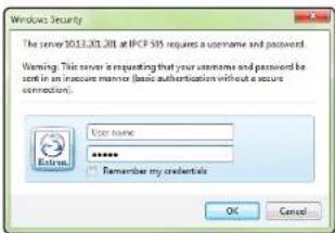
Figure 48. The Windows Security Dialog Box
- Click on the Configuration tab, then select Firmware Upgrade from the list on the left of the screen. The Firmware Upgrade screen appears.
- Click the Browse button. The Choose File to Upload dialog box opens (see figure 49).
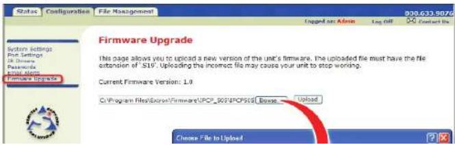
- Click on the Upload button on the web page to upload the firmware to the controller. It takes a while to load the file into the IPCP. You will not see any on-screen indication when the upload has finished. Once the firmware upload is completed, the IPCP performs a reset.
- If necessary, see Resetting the Unit starting on page 16 in for details about manually resetting the controller or see the Global Configurator Help file to learn how to restore a configuration to the controller.
Updating Firmware via Extron Firmware Loader Software
This method allows you to update one IPCP at a time via IP communication using Firmware Loader software (available free at www.extron.com.
NOTE: The IPCP requires Firmware Loader version 5.0.1 or higher.
- If not already installed, download Firmware Loader from the Extron website and follow the on-screen instructions to install it.
- Download the .s19 firmware file to the PC.
- Start the Firmware Loader (FWLoader, software on the connected PC. The Add Device dialog box opens.
- In the Add Device dialog box, choose the type of device (IPCP), the communication type (select TCP/IP), and, if necessary, set the communication settings. Enter the IP address of the controller, verify or change the Telnet port number, and enter an administrator password if a password has been set for the unit.
NOTE: Passwords must contain 4 to 12 alphanumeric characters. Symbols and spaces are not allowed, and the passwords are case sensitive.
- Click the Connect button. If the connection is unsuccessful, an error message is displayed. If the connection is successful, the IPCP model name is displayed within the dialog box and the New Firmware File panel becomes accessible.
- Click the Browse button. The Open window appears.
- Locate and select the firmware file on your PC that you downloaded for the IPCP, then
Index
Symbols
0.evt 5
.ein
file type description 77
.eml
file type description 77
.evl
file type description 77
.gc2
file type description 77
.gcz
file type description 77
/nortxe_index.html
factory-embedded web pages 36
.s19
downloading the file for a firmware upgrade 81
file type description 77
uploading via the Firmware
Upgrade embedded web
page 42
C
cdc files 43
description of file type 77
COM1-COM8 RS-232 ports
use and wiring
COM1-COM6 12
COM7, COM8 12
command/response table for SIS
commands 57
configuration
saving and uploading 36
Configuration embedded web
page 39
controlling an IPCP 36
crossover network cable
used for configuration via T
elnet 23
custom GUI service 48
customizing control web pages 48
D
defaults
LAN port 13
DO 229 protocol for COM
display control 4
distance
IR learning distance from remote
to IPCP 9
to display or projector 12
drivers
customized IR driver files, IR
learning and 29
definition of term 75
device driver communication
sheet 12
device drivers provided by
Extron, also IR learning to make
customized drivers 27
driver subscription feature of
Global Configurator 28
.eir file type 77
Ethernet drivers 2
IR learning sensor and creating a
device driver file 9
IR or RS-232 driver file,
downloading and using for
control 4
serial bridging and RS-232 driver
disabling 34
viewing information on IR driver
embedded web pages
accessing 36
accessing factory-set pages on
a unit that also has GV web
pages 36
Configuration 39
IR Drivers 41
Port Settings 40
Email Alerts 42
File Management 43
Firmware Upgrade 42
Status 37
System Status 37
updating firmware via 83
eml file type 77
Ethernet drivers
support for 2
Ethernet (LAN) port configuration
and use
SIS commands for 59
event (.evt) files
caution 43
description and caution 77
main event file (0.evt) 5
what they are used for, how
they interact with hardware and
software 5
Extron Firmware Loader software 85
Extron IP Link File Manager
software 82

file extension
.cdc 43,77
firmware
determining the firmware
version 78
SIS commands 62
firmware update file type 77
locating and downloading 81
.s19 file 77
SIS commands for firmware
versions 62
updating 30
IP Link File Manager
software 82
updating the main firmware 81
via embedded web page 42, 83
via Extron Firmware Loader
software 85
Firmware Loader software 85
Firmware Upgrade embedded web
page 42,83
flex I/O ports
description, wiring 15
SIS commands 61

gateway IP address
default value 13
resetting to default (reset modes 4
and 5) 17
SIS commands for 65
GC configuration file
*.gc2 77
*.gcz 77
Global Configurator software
GUI configuration report

IP address
resetting to default (reset modes 4 and 5) 17
IP Link File Manager software 82
IR and RS-232 device control 4
1R drivers
IR driver file type (.eir files) 77
using IR learning to create
customized drivers 29
viewing and triggering
functions 41
1R Drivers embedded web page and
control 41
1R emitters
wiring for use with IR output
ports 14
IR Learner software version 29
1R learning
distances and angles 9
frequencies accepted by the
controller 9
purpose and software 29
receiver/sensor location and
use 9,29
IR output ports
SIS commands for 60
use and wiring 14
1R signal sensor (1R learning receiver)
location, use, reception angle 9
using to capture IR commands 29

model description
SIS command for model
description 63
model name
as shown in the copyright boot-up
message 50
SIS command to request 63
modes
DHCP mode and SIS
commands 65
IR playback mode variable in SIS
commands 60
reset modes and procedures 16
reset mode SIS commands 74
serial communication standard
(RS-232/RS-422/RS-485)
SIS commands 58
serial pass-through mode
SIS commands for 59
verbose (description and SIS
commands for) 66
momentary
relay description and wiring 15
mounting
UL rack mounting guidelines 10
N
nortxe index.html factory embedded
web pages 36
P
part numbers
SIS command for 69
Port Settings embedded web
page 40
power connector
switched power output port
SIS commands for 62
wiring, polarity, requirements
input power 11
output power 11
R
rack mounting
UL rack mounting guidelines 10
redirect mode
serial pass-through (redirect
modei 32
relay ports
latching; description and
wiring 15
momentary contact: description
and wiring 15
SIS commands for 61
wiring 15
remapping ports
SIS commands for 68
reserved characters 52
Reset button
Reset button and LED location 9
using to reset the unit 16
resetting the unit
manual reset modes 16
reset after firmware update 82
reset (zap) commands and erase
commands (SIS) 74
reset (zap) commands and erase
serial ports
advanced control methods 31
direct port access (ports 2001
through 2003) 32
serial bridging 33
serial pass-through (redirect
mode) 32
SIS CP command to configure
parameters for each port 58
wiring COM ports 12
wiring IR/Serial ports 14
SIS commands
commands and responses 57
helpful tips for entering and
encoding 52
symbol definitions for 53
straight-through cable (wiring and
when to use) 13
subnet
default value 13
definition of subnet mask 76
resetting to default (reset modes 4
and 5) 17
SIS commands for setting and
reading 65
Switched 12 VDC power output port
SIS commands for 62
symbol definitions for SIS
commands 53
system requirements 6
System Settings (GlobalViewer web
page) 39
T
U
Underwriters Laboratories (UL) UL rack mounting guidelines 10 unit name
definition and parameters 28, 39 SIS CN commands to set or read 64
updating the main firmware 81
V
verbose mode SIS commands for 66 variables for, and description 54
W
wiring block diagram printing 30
z
Zap (reset) commands SIS commands to reset the unit and/or erase files 74
Extron Warranty
Extron Electronics warrants this product against defects in materials and workmanship for a period of three years from the date of purchase. In the event of malfunction during the warranty period attributable directly to faulty workmanship and/or materials, Extron Electronics will, at its option, repair or replace said products or components, to whatever extent it shall deem necessary to restore said product to proper operating condition, provided that it is returned within the warranty period, with proof of purchase and description of malfunction to:
USA, Canada, South America, and Central America:
Extron Electronics
1230 South Lewis Street
Anaheim, CA 92805
U.S.A.
Japan:
Extron Electronics, Japan
Kyodo Building, 16 Ichibancho
Chiyoda-ku, Tokyo 102-0082
Japan
Europe and Africa:
Extron Europe
Hanzeboulevard 10
3825 PH Amersfoort
The Netherlands
China:
Extron China
686 Ronghua Road
Songjiang District
Shanghai 201611
China
Asia:
Extron Asia Pte Ltd
135 Joo Seng Road, #04-01
PM Industrial Bldg.
Singapore 368363
Singapore
Middle East:
Extron Middle East
Dubai Airport Free Zone
F12, PO Box 293666
United Arab Emirates, Dubai
This Limited Warranty does not apply if the fault has been caused by misuse, improper handling care, electrical or mechanical abuse, abnormal operating conditions, or if modifications were made to the product that were not authorized by Extron.
NOTE: If a product is defective, please call Extron and ask for an Application Engineer to receive an RA (Return Authorization) number. This will begin the repair process.
IEA: 714 404 1600 or 900 829 0976
Europa: 21 22 452 4040
- Safety Instructions
- Safety Instructions • English
- Chinese Simplified (简体中文)
- Chinese Traditional (繁體中文)
- Conventions Used in this Guide
- Notifications
- Software Commands
- Contents
- Introduction 1
- Hardware Features and Installation 7
- Software-based
- Configuration and Control ....18
- SIS Programming and Control....50
- Firmware Updates....78
- Reference Information 75
- Index 86
- Introduction
- Before You Begin
- Network and configuration features
- Application Diagrams
- IR and RS-232 Device Control
- How the IPCP 505 Works: Components and Interactions
- System Requirements
- Hardware Features and Installation
- Setup Checklist:
- How to Proceed With Installation
- Prepare
- Front Panel Features
- IR Learning Sensor
- Mounting the IPCP 505
- UL Rack Mounting Guidelines
- Power Connections
- Cabling:
- Unidirectional Control and Communication Connections
- Resetting the Unit
- Software-based Configuration and Control
- Configuration and Control: an Overview
- Basic Setup Steps: a Guide to this Section and Other Resources
- Communicating with the IPCP
- IPCP 505 LAN port defaults:
- Configuring the IPCP for Network Use Via Global Configurator
- Configuring the IPCP for Network Use Via the ARP Command
- Configuring the IPCP for Network Use Via a Web Browser
- NOTES:
- Configuring the IPCP for Network Use Via SIS Commands and Telnet
- Global Configurator Software for Windows®
- Downloading the Software and Getting Started
- Using Global Configurator: Helpful Tips
- Resources and Notes
- A Brief Guide to Tabs in Global Configurator
- Advanced Configuration
- Printing a Wiring Block Diagram or a GUI Configuration Report
- Procedure overview:
- Updating Firmware
- Advanced Serial Port Control
- Serial pass-through (redirect mode)
- Hardware connection
- Saving and Uploading the Configuration
- Controlling an IPCP 505
- Embedded Web Pages
- Status
- System Status
- Configuration
- System Settings
- Port Settings
- IR Drivers
- Passwords
- Email Alerts
- Firmware Upgrade
- File Management
- GlobalViewer Web Pages
- Controlling the IPCP 505 with a Touchpanel
- Customizing the IPCP Control Web Pages
- Troubleshooting
- Data Connections
- SIS Programming and Control
- Host-to-IPCP Communications
- Password Information
- Error Responses
- Error Response References
- Entering SIS Commands: Helpful Tips
- Symbol Definitions
- Relay ports: Flex I/O ports:
- Switched power output ports:
- Examples:
- Command/Response Table for SIS Commands
- Command/Response Table for SIS Commands (continued)
- Reference Information
- Glossary
- ARP (Address Resolution Protocol)
- DHCP (Dynamic Host Configuration Protocol)
- MAC (Media Access Control) Address
- Ping
- Port number
- SSI (server side include)
- Static IP
- Subnet — See subnetwork.
- Subnet address
- Subnet mask
- Subnetwork
- TCP (Transmission Control Protocol)
- TCP/IP (Transmission Control Protocol/Internet Protocol)
- Verbose
- File Types: a Key to Extron-specific File Names
- Firmware Updates
- Determining the Firmware Version
- Using the Global Configurator Software
- Updating the Main Firmware
- Locating and Downloading the Firmware
- Updating Firmware via Extron IP Link File Manager Software
- Updating Firmware via Extron Firmware Loader Software
- Index
- Symbols
- C
- D
- N
- P
- R
- T
- Extron Warranty
- USA, Canada, South America, and Central America:
- Japan:
- Europe and Africa:
- China:
- Asia:
- Middle East:
Brand : Extron
Model : IPCP 505
Category : AV Controller