
DHB-E 13 AU - Water heater STIEBEL ELTRON - Free user manual and instructions
Find the device manual for free DHB-E 13 AU STIEBEL ELTRON in PDF.


| Product type | Electronically controlled instantaneous water heater |
| Model | DHB-E 13 AU |
| Brand | Stiebel Eltron |
| Dimensions (HxWxD) | 493 x 225 x 140 mm (approx.) |
| Weight | Approx. 4.0 kg (without water) |
| Power supply | 3/PE ~ 380-415 V, 50/60 Hz |
| Rated output | 12.2 – 14.5 kW (depending on voltage) |
| Rated current | 18.5 – 20.2 A |
| Fuse/MCB rating | 20 A |
| Water connection | G 1/2 A male thread |
| Max. permissible pressure | 1.0 MPa |
| Max. inlet temperature | 80 °C (reheating: 45 °C) |
| Flow rate to switch on | >3.0 L/min |
| Flow rate limit (factory set) | 7.5 L/min |
| DHW delivery at ΔT 28 K | 6.9 L/min |
| Temperature adjustment | Variable, with anti-scalding limit at 43 °C (adjustable) |
| Control type | Electronic with automatic power matching |
| Installation | Vertical, undersink or oversink, indoor frost-free location |
| Maintenance | Clean strainer in cold water inlet; descale aerator/shower head as needed |
| Safety features | High limit safety cut-out, safety pressure limiter, air sensor, LED diagnostic traffic light |
| Warranty | 1 year on all components (Australia) |
Frequently Asked Questions - DHB-E 13 AU STIEBEL ELTRON
User questions about DHB-E 13 AU STIEBEL ELTRON
0 question about this device. Answer the ones you know or ask your own.
Ask a new question about this device
Download the instructions for your Water heater in PDF format for free! Find your manual DHB-E 13 AU - STIEBEL ELTRON and take your electronic device back in hand. On this page are published all the documents necessary for the use of your device. DHB-E 13 AU by STIEBEL ELTRON.
USER MANUAL DHB-E 13 AU STIEBEL ELTRON
Electronically controlled instantaneous water heater
1.1 Safety instructions 3
1.2 Other symbols in this documentation 3
1.3 Units of measurement 3
- Safety 3
2.1 Intended use 3
2.2 General safety instructions 3
2.3 CE designation ____ 4
2.4 Test symbols ____ 4
-
Appliance description ____ 4
-
Settings 4
4.1 Following an interruption of the water supply ____ 4
-
Cleaning, care and maintenance ____ 4
-
Troubleshooting 5
INSTALLATION
- Safety 6
7.1 General safety instructions 6
7.2 Instructions, standards and regulations ____ 6
- Appliance description 6
8.1 Standard delivery 6
- Preparations 6
9.1 Installation site ____ 7
- Installation 7
10.1 Standard installation 7
10.2 Completing the installation ____ 10
10.2 Installation options 10
SPECIAL INFORMATION
The appliance may be used by children aged 8 and up and persons with reduced physical, sensory or mental capabilities or a lack of experience and know-how, provided that they are supervised or they have been instructed on how to use the appliance safely and have understood the resulting risks. Children must never play with the appliance. Children must never clean the appliance or perform user maintenance unless they are supervised.
Ensure the appliance can be separated from the power supply by an isolator that disconnects all poles with at least 3 mm contact separation.
Secure the appliance as described in chapter "Installation / Installation".
Observe the maximum permissible pressure (see chapter "Specification / Data table").
Drain the appliance as described in chapter "Installation / Maintenance / Draining the appliance".
OPERATION
General information
OPERATION
1. General information
The chapter "Operation" is intended for appliance users and qualified contractors.
The chapter "Installation" is intended for qualified contractors.

Note
Read these instructions carefully before using the appliance and retain them for future reference. Pass on the instructions to a new user if required.
1.1 Safety instructions
1.1.1 Structure of safety instructions

KEYWORD Type of risk
Here, possible consequences are listed that may result from failure to observe the safety instructions.
▶ Steps to prevent the risk are listed.
1.1.2 Symbols, type of risk
Symbol Type of risk

Injury

Electrocution
1.2 Other symbols in this documentation

Note
Notes are bordered by horizontal lines above and below the text. General information is identified by the symbol shown on the left.
▶ Read these texts carefully.
Symbol

Material losses
(appliance damage, consequential losses and environmental pollution)

Appliance disposal
This symbol indicates that you have to do something. The action you need to take is described step by step.
1.3 Units of measurement

Note
Unless specified otherwise, all dimensions are given in mm.
2. Safety
2.1 Intended use
This appliance is intended for domestic use. It can be used safely by untrained persons. The appliance can also be used in a non-domestic environment, e.g. in a small business, as long as it is used in the same way.
This procedure tested simplifies is suitable for hosting domestic hot
ENGLISH
OPERATION
Appliance description

Damage to the appliance and environment
Protect the appliance and its tap against frost.
2.3 CE designation
The CE designation shows that the appliance meets all essential requirements according to the:
- Low Voltage Directive
- Electromagnetic Compatibility Directive
The maximum permissible mains impedance is indicated in chapter "Specification".
2.4 Test symbols
See type plate on the appliance
Information for Australia/New Zealand:
Installation complies with standard AS/NZS 3500.4.
3. Appliance description
The electronically controlled instantaneous water heater with automatic output matching maintains a consistent outlet temperature. This occurs irrespective of the inlet temperature, up to the maximum output. The DHW outlet temperature can be variably adjusted.
DHW temperature
The DHW outlet temperature can be variably adjusted.
Temperature limit / Anti-scalding protection
The maximum outlet temperature for the appliance can be limited to 43 °C. For this, contact your local heating contractor.
4. Settings
DHB-E 13 AU
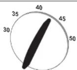
16.02.02.1382
DHB-E 18 AU | DHB-E 27 AU
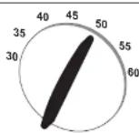
16.02.02.1381
Should the outlet temperature fail to reach the required level with the draw-off valve fully open and the temperature selector set to maximum, then more water is flowing through the appliance than can be heated by the heating element.
▶ Reduce the flow rate at the draw-off valve.
Recommended setting for operation with a thermostatic valve and water preheated by solar energy
▶ Set the temperature at the appliance to the max. temperature.
4.1 Following an interruption of the water supply
OPERATION Troubleshooting
- Troubleshooting
| Fault Cause Remody | ||
| The appliance will not start despite the DIHW valve being fully open. | There is no voltage in the appliance. | Check the fuses/WCBs in your fuse box/distribution panel. |
| The aerator in the lap or the shower head is scaled up or contaminated. | Clean and/or descale the aerator or shower head. | |
| The water supply has been interrupted. | Vent the appliance and the cold water inlet line (see chapter "Settings / Following an interruption to the water supply"). | |
| Cold water flows briefly while hot water is being drawn. | The air sensor detects air in the water and the appliance's heating output is briefly switched off. | The appliance restarts automatically after 1 minute. |
| Required temperature >45 °C is not achieved. | The appliance no longer delivers heat. The cold water inlet temperature is >45 °C. | Reduce the cold water inlet temperature. |
If you cannot remedy the fault, notify your qualified contractor. To facilitate and speed up your enquiry, please provide the serial number from the type plate (000000-0000-000000):
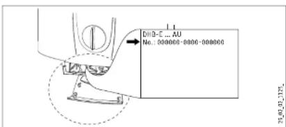
INSTALLATION
Safety
INSTALLATION
7. Safety
Only a qualified contractor should carry out installation, commissioning, maintenance and repair of the appliance.
7.1 General safety instructions
We guarantee trouble-free function and operational reliability only if original accessories and spare parts intended for the appliance are used.
Flow pressure
If the flow rate is not sufficient to switch on the appliance even when the tap is open, remove the flow limiter and replace it with the plastic profile washer supplied.
If required, the pressure in the water installation can also be raised.

Note If a thermostatic valve is used, you must not replace the flow limiter with the plastic profile washer.

Material losses Observe the maximum inlet temperature. Higher temperatures may damage the appliance. You can limit the maximum inlet temperature by installing a central thermostatic valve.
72 Instructions, standards and regulations
8. Appliance description
8.1 Standard delivery
The following are delivered with the appliance:
- Mounting bracket
- Installation template
- 2 plugs
- 2 extensions
- 2 caps
- 2 tees
- 8 flat gaskets
- Strainer
- Flow limiter
- Plastic profile washer
- Plastic cap
- Flexible plastic couplings
- Cover and back panel guides
9. Preparations
▶ Flush the water line thoroughly.
Taps/valves
▶ Use appropriate pressure-tested taps. Open taps are not permitted.
A safety valve is not required.
Permissible water pipe materials
- Cold water inlet pipe:
Galvanised steel pipe, stainless steel pipe, copper pipe or plastic pipe
INSTALLATION
Installation
9.1 Installation site

Material losses
Only install the appliance in rooms free from the risk of frost.
▶ Always install the appliance vertically near the draw-off point.
The appliance is suitable for undersink and oversink installations.

Note
Mount the appliance on a sufficiently load-bearing wall.
Undersink installation
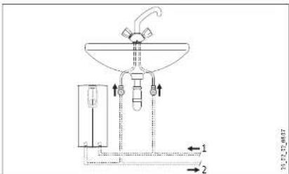
1 Cold water inlet
2 DHW outlet
Oversink installation
10. Installation
10.1 Standard installation
- Electrical connection in the lower section of the appliance for installation on unfinished walls
- Water connection for installation on finished walls
For further installation options, see chapter "Installation options".
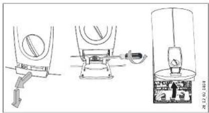
▶ Open the appliance.
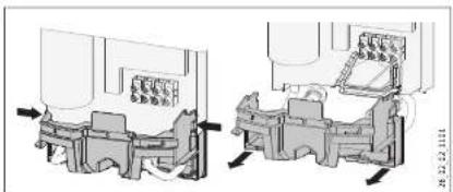
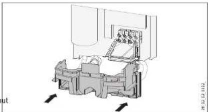
Remove the back panel by pressing the two locking hooks and pulling the lower part of the back panel forwards
ENGLISH
INSTALLATION
Installation
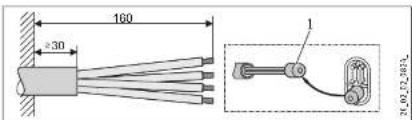
1 Installation aid
▶ Prepare the power cable.
Preparing the water connection

natural_image
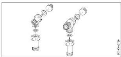
Exploded view diagram of mechanical components (no text or labels)▶ Remove the caps from the tees.
▶ Fit the plugs and the extensions with gaskets.
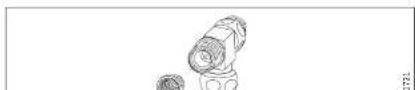


Install the flow limiter.
- With low water pressure. The pressure drop can be reduced by replacing the flow limiter with the plastic profile washer provided.
Installing the appliance
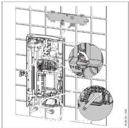
natural_image
Technical line drawing of an electrical enclosure with internal components and a magnified inset showing mechanical assembly (no text or labels)▶ For easy installation, push the cable grommet of the upper electrical connection into the back panel from behind.
▶ Remove the transport plugs from the water connections.
INSTALLATION
Installation
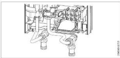
natural_image
Technical line drawing of a mechanical assembly with no visible text or symbols▶ Screw the pre-assembled parts with flat gaskets to the cold water and DHW pipes of the appliance.
▶ Fit the cold water inlet pipe and the DHW outlet pipe from the pipework with flat gaskets to the extensions from the appliance.
Making the electrical connection

WARNING Electrocution
Carry out all electrical connection and installation work in accordance with relevant regulations.

WARNING Electrocution
Connection to the power supply is only permissible in the form of a permanent connection in conjunction with the removable cable grommet. Ensure the appliance can be separated from the power supply by an isolator that disconnects all poles with at least 3 mm contact separation.

WARNING Electrocution
Ensure that the appliance is earthed.

Damage to the appliance and environment
Observe the type plate. The specified voltage must match
Lower back panel installation
ENGLISH
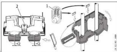
1 Connection pieces delivered in the pack
2 Screw
▶ Cut open the lower part of the back panel (see illustration).
▶ Fit the lower back panel by bending it out at the sides and guiding it over the pipes.
▶ Insert the connection pieces into the lower back panel from behind.
▶ Click the lower back panel into place.
▶ Align the mounted appliance by loosening the fixing toggle, aligning the power supply and back panel, and then re-tightening the fixing toggle.
▶ Secure the lower back panel with a screw.
INSTALLATION
Installation
10.2 Completing the installation
▶ Open the shut-off valve in the cold water inlet line.
Fitting the sealing elements for the appliance cover
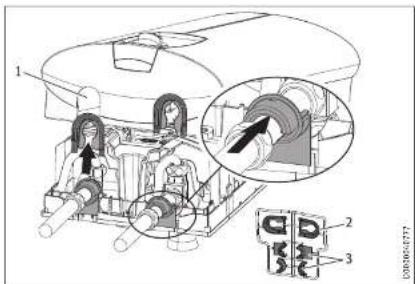
1 Pipe aperture
2 Cover guides
3 Back panel guides
Material losses ! If you cut open the wrong knock-out in the appliance cover by mistake, you must use a new appliance cover.
- Cleanly cut or break out the knock-out openings in the appliance cover. If necessary, use a file.
Note You can compensate for a slight connection pipe offset using the tabs on the cover guides. If the connection pipes are offset, do not fit any back panel guides.
10.3 Installation options
- Electrical connection from above on unfinished walls
- Electrical connection for finished walls
- Large cross-section for electrical connection from below
- Water installation on unfinished walls
- Wall mounting bracket when replacing an appliance
- Installation with offset tiles
- Pivoting appliance cover
- Operation with preheated water
- Temperature limitation / Anti-scalding protection
Electrical connection from above on unfinished walls
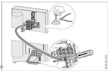
natural_image
Diagram of a mechanical assembly with labeled parts and an inset showing a tool interacting with a component (no text or symbols present)▶ Cut open the cable grommet for the power cable.
▶ Push down the locking hook to secure the mains terminal. Pull out the mains terminal.
▶ Reposition the mains terminal in the appliance from the bottom to the top and secure the mains terminal by sliding it
INSTALLATION
Installation
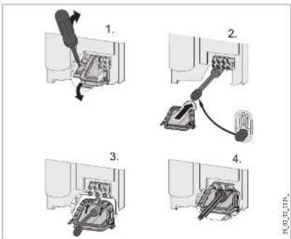
▶ Before installing the appliance, use a screwdriver to push out the cable grommet.
▶ Slide the cable grommet over the power cable. For this, use the installation aid. If the cross-section is > 6 mm², enlarge the hole in the cable grommet.
▶ Push the cable grommet into the back panel.
Water installation on unfinished walls
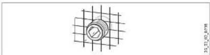
natural_image
Technical drawing of a bolted joint with grid pattern (no text or symbols)
Damage to the appliance and environment
The strainer must be fitted for the appliance to function.
When replacing the appliance, check that the s r is present.
▶ Screw the connection pipes from the appliance to the tee.
▶ Open the shut-off valve in the cold water inlet line.
natural_image
Technical line drawing of a mechanical assembly with no visible text or symbolsENGLISH
▶ Fit the lower part of the back panel. Ensure that it clicks into place.
Align the mounted appliance by loosening the fixing toggle, aligning the power supply and back panel, and then re-tightening the fixing toggle. If the back panel of the appliance is not flush, the appliance can be secured at the bottom with an additional screw
Wall mounting bracket when replacing an appliance
When replacing an appliance, you can use an existing wall mounting bracket of a Stiebel Eltron appliance (except for a DHF instantaneous water heater).
▶ Press the appliance over the threaded stud of the existing
▶ Seal and screw in the twin connectors (not included in stand-
INSTALLATION
Installation
Installation with offset tiles
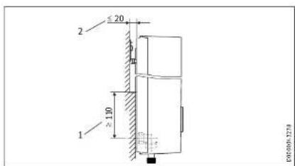
1 Minimum contact area of the appliance
2 Maximum tile offset
Adjust the wall clearance. Lock the back panel with the fixing toggle by turning it 90° clockwise.
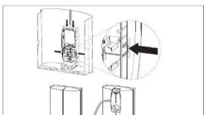
Pivoting appliance cover
You can rotate the appliance cover for undersink installation.
natural_image
Technical diagram showing mechanical assembly with cross-section and detail views (no text or labels)Temperature limitation / Anti-scalding protection
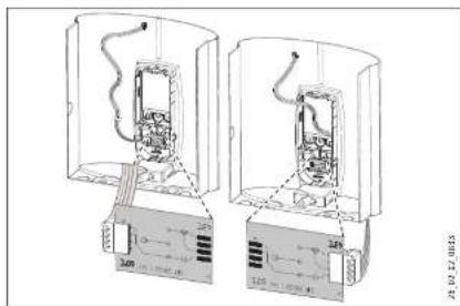
The maximum temperature can be limited to 43 °C via the programming unit on the appliance cover. For this, the following steps are necessary:
▶ Remove the appliance cover.
Remove the electronic PCB from the programming unit on the appliance cover. Be careful with the snap-on hooks.
▶ Move the plug from left to right (position "43 °C").
▶ Refit the programming unit, ensuring the snap-on hooks pick into place. Observe the positions of the push-button and shaft.

CAUTION Burns
When operating with preheated water, the set temperature limit / anti-scalding protection may be ineffective.
▶ In this case, limit the temperature at the upstream central thermostatic valve.
natural_image
Technical line drawing of two electrical enclosure units with internal components and wiring (no text or symbols)INSTALLATION
Commissioning
11. Commissioning

WARNING Electrocution
Commissioning may only be carried out by a qualified contractor in accordance with safety regulations.
12. Shutting down the system
▶ Isolate all poles of the appliance from the power supply.
Drain the appliance (see chapter "Maintenance").
ENGLISH
11.1 Initial start-up
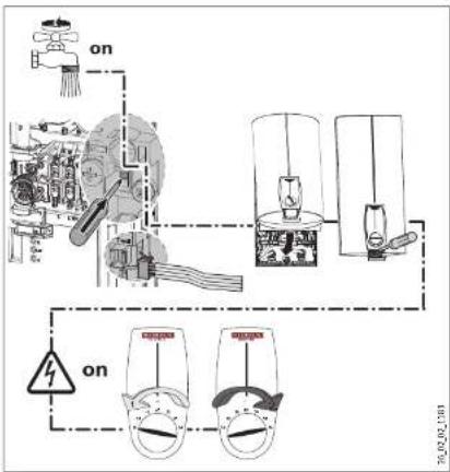
▶ Open and close all connected draw-off valves several times, until all air has been vented from the pipework and the
INSTALLATION
Troubleshooting
13. Troubleshooting

WARNING Electrocution
In order to check the appliance it must be connected to the power supply.
13.1 Indicator options for LED diagnostic traffic light
Indicator options
Red illuminates in the event of a fault
Yellow illuminates during heating mode
Green Flashing: Appliance is supplied with mains power
13.2 Fault table
| Fault / diagnostic traffic light LED display | Cause: Remedy | |
| The appliance does not start. | The shower head / aerators are scaled up. | Descal or if necessary replace the shower head / aerators. |
| Inadequate flow rate. | The strainer in the appliance is dirty. | Clean the strainer. |
| The set temperature is not achieved. | One phase down. | Check the fuses/MCBs in your fuse box/distribution panel. |
| The heater switches off. | The air sensor detects the presence of air in the water and briefly interrupts the heating output. | The appliance restarts after one minute. |
| No hot water and no traffic light display. | The MCB/fuse has responded/blown. | Check the fuses/MCBs in your fuse box/distribution panel. |
| Safety pressure limiter AP 3 has tripped. | Remove the cause of the fault (e.g. faulty pressure washer). | |
| Protect the heating system against overheating by opening a draw-off valve downstream from the appliance for one minute. This depressurises and cools down the heating system. | ||
| Activate the safety pressure limiter at flow pressure by pressing the reset button; see also chapter "Commissioning / Initial start-up". | ||
| The PCB is faulty. | Check the PCB and replace if necessary. | |
| Traffic light display: Green flashing No hot water at flow role > 3 L/min. | Flow sensor DFE is not plugged in. | Plug the flow sensor plug back in. |
| Flow sensor DFE is faulty. | Check the flow sensor and replace if necessary. |
INSTALLATION
Maintenance
14. Maintenance

WARNING Electrocution
Before any work on the appliance, disconnect all poles from the power supply.
Draining the appliance
You can drain the appliance for maintenance work.

CAUTION Scalding
Hot water may escape when draining the appliance.
▶ Close the shut-off valve in the cold water inlet line.
▶ Open all draw-off valves.
▶ Undo the water connections on the appliance.
- Store the dismantled appliance in a room free from the risk of frost, as water residues remaining inside the appliance can freeze and cause damage.
Cleaning the strainer
A strainer is located in the tee from the cold water inlet pipe. In case of contamination, you can remove this strainer and clean it.
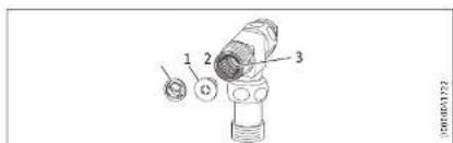
1 Flow limiter or
2 Plastic profile washer
15. Specification
15.1 Dimensions and connections
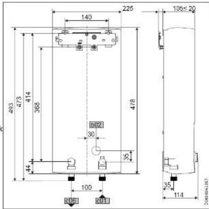
b02 Entry electrical cables
c01 Cold water inlet Male thread G 1/2 A
c06 DHW outlet Male thread G 1/2 A
Alternative connection options

ENGLISH
INSTALLATION
Specification
15.2 Wiring diagram
3/PE \~ 380-415 V
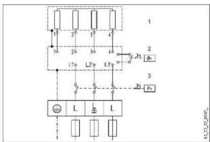
1 Heater
2 High limit safety cut-out
3 Safety pressure limiter
15.3 DHW output
DHW output is subject to the mains voltage, the appliance's connected load and the cold water inlet temperature. The rated voltage and rated output can be found on the type plate (see chapter 'Troubleshooting').
Connected load in kW 38 °C DHW output in L/min.
Rated voltage Cold water inlet temperature
| 380 V | 400 V | 415 V | 5 °C | 10 °C | 15 °C | 20 °C |
| 10.1 | 4.4 | 5.2 | 6.3 | 8.0 | ||
| 11.0 | 4.8 | 5.6 | 6.8 | 8.7 | ||
| 12.0 | 5.2 | 6.1 | 7.5 | 9.5 |
Connected load in kW 50 °C DHW output in L/min.
Rated voltage Cold water inlet temperature
| 380 V | 400 V | 415 V | 5 °C | 10 °C | 15 °C | 20 °C |
| 10.1 | 3.2 | 3.6 | 4.1 | 4.8 | ||
| 11.0 | 3.5 | 3.9 | 4.5 | 5.2 | ||
| 12.0 | 3.8 | 4.3 | 4.9 | 5.7 | ||
| 12.2 | 3.9 | 4.4 | 5.0 | 5.8 | ||
| 13.2 | 4.2 | 4.7 | 5.4 | 6.3 | ||
| 13.5 | 4.3 | 4.8 | 5.5 | 6.4 | ||
| 13.6 | 4.3 | 4.9 | 5.6 | 6.5 | ||
| 14.2 | 4.5 | 5.1 | 5.8 | 6.8 | ||
| 14.5 | 4.6 | 5.2 | 5.9 | 6.9 | ||
| 15.0 | 4.8 | 5.4 | 6.1 | 7.1 | ||
| 16.2 | 16.2 | 5.1 | 5.8 | 6.6 | 7.7 | |
| 16.3 | 5.2 | 5.8 | 6.7 | 7.8 | ||
| 18.0 | 5.7 | 6.4 | 7.3 | 8.6 | ||
| 19.0 | 6.0 | 6.8 | 7.8 | 9.0 | ||
| 19.4 | 6.2 | 6.9 | 7.9 | 9.2 | ||
| 21.0 | 6.7 | 7.5 | 8.6 | 10.0 | ||
| 21.7 | 6.9 | 7.8 | 8.9 | 10.3 | ||
| 22.6 | 7.2 | 8.1 | 9.2 | 10.8 | ||
| 23.5 | 7.5 | 8.4 | 9.6 | 11.2 | ||
| 24.0 | 7.6 | 8.6 | 9.8 | 11.4 | ||
| 24.4 | 7.7 | 8.7 | 10.0 | 11.6 | ||
| 25.8 | 8.2 | 9.2 | 10.5 | 12.3 | ||
| 26.0 | 8.3 | 9.3 | 10.6 | 12.4 | ||
| 27.0 | 8.6 | 9.6 | 11.0 | 12.9 | ||
| 28.0 | 8.9 | 10.0 | 11.4 | 13.3 | ||
| 29.1 | 9.2 | 10.4 | 11.9 | 13.9 |
15.4 Application areas / conversion table
Specific electrical resistance and specific electrical conductivity (see chapter "Data table").
Standard specifi-
cation
INSTALLATION
Specification
15.6 Fault conditions
In case of faults, loads up to 95 °C at a pressure of 1.0 MPa can occur temporarily in the installation.
15.7 Data table
| DHB-E 13 AU DHB-E 18 AU DHB-E 27 AU | ||||||||||
| 232360 233986 233987 | ||||||||||
| Electrical data | ||||||||||
| Rated voltage | V | 380 | 400 | 425 | 380 | 400 | 425 | 380 | 400 | 425 |
| Rated output | kW | 12.2 | 13.5 | 14.5 | 16.2 | 18 | 19.4 | 23.5 | 26 | 28 |
| Rated current | A | 18.5 | 19.5 | 20.2 | 24.7 | 26 | 27 | 35.6 | 37.7 | 38.9 |
| Fuse/MCB rating | A | 20 | 20 | 20 | 25 | 25 | 32 | 40 | 40 | 40 |
| Phases | 3/PE | 3/PE | 3/PE | |||||||
| Frequency | Hz | 50/60 | 50/60 | 50/^2 | 50/60 | 50/60 | 50/^2 | 50/^2 | 50/^2 | 50/^2 |
| Specific resistance _15 ≥ at cold≤ 25^ C | 0 cm | 900 | 900 | 1000 | 900 | 900 | 1000 | 900 | 900 | 1000 |
| Specific conductivity _15 ≤ ( at cold≤ 25^ C) | μS/cm | 1111 | 1111 | 1000 | 1111 | 1111 | 1000 | 1111 | 1111 | 1000 |
| Specific resistance _15 ≥ at cold≤ 45^ C | 0 cm | 1200 | 1200 | 13000 | 1200 | 1200 | 1300 | 1200 | 1200 | 1300 |
| Specific conductivity _15 ≤ ( at cold≤ 45^ C) | μS/cm | 833 | 833 | 770 | 833 | 833 | 770 | 833 | 833 | 770 |
| Max. mains impedance at 50Hz | U | 0.474 | 0.450 | 0.433 | 0.316 | 0.300 | 0.289 | |||
| Max. mains impedance at 60Hz | O | 0.392 | 0.372 | |||||||
| Connections | ||||||||||
| Water connection | G 1/2 A | G 1/2 A | G 1/2 A | |||||||
| Application limits | ||||||||||
| Max. permissible pressure | MPa | 1 | 1 | 1 | ||||||
| Max. inlet temperature for reheating | °C | 45 | 45 | 45 | ||||||
| Values | ||||||||||
| Max. permissible inlet temperature | °C | 80 | 80 | 60 | ||||||
| On | U/min | >3.0 | >3.0 | >3.0 | ||||||
| Flow rate for pressure drop | U/min | 5.2 | 5.2 | 7.7 | ||||||
| Pressure drop at flow rate | MPa | 0.08 (0.06 without DWBI) | 0.08 (0.06 without DWBI) | 0.15 (0.12 without DWBI) | ||||||
| Flow rate limit at | U/min | 7.5 | 7.5 | 8.5 | ||||||
| DHW delivery | U/min | 6.9 | 9.2 | 13.8 | ||||||
| ΔB on delivery | K | 28 | 28 | 28 | ||||||
| Hydraulic data | ||||||||||
| Nominal capacity | I | 0.4 | 0.4 | 0.4 | ||||||
Warranty
The warranty conditions of our German companies do not apply to appliances acquired outside of Germany. In countries where our subsidiaries sell our products, it is increasingly the case that warranties can only be issued by those subsidiaries. Such warranties are only granted if the subsidiary has issued its own terms of warranty. No other warranty will be granted.
We shall not provide any warranty for appliances acquired in countries where we have no subsidiary to sell our products. This will not affect warranties issued by any importers.
Environment and recycling
We would ask you to help protect the environment. After use, dispose of the various materials in accordance with national regulations.
Stiebel Eltron Warranty for Water Heaters - Models DHB-E AU
Who gives the warranty
- The warranty is given by Stiebel Eltron (Aust) Pty Ltd (A.B.N. 82 066 271 083) of Unit 4/8 Rocklea Drive, Port Melbourne, Victoria, 3207 ("we", "us" or "our").
The warranty
-
This warranty applies to Stiebel Eltron Water Heaters – Models DHB-E 13 AU, DHB-E 18 AU and DHB-E 27 AU (the "unit") manufactured after 1 March 2014.
-
Subject to the warranty exclusions we will repair or replace, at our absolute discretion, a faulty component in your unit free of charge if it fails to operate in accordance with its specifications during the warranty period.
Component Warranty period
All components 1 year from the date of completion of the installation of the unit.
Your entitlement to make a warranty claim
- You are entitled to make a warranty claim if:
8.1. you own the unit or if you have the owner's consent to represent the owner of the unit;
8.2. you contact us within a reasonable time of discovering the problem with the unit; How you make a warranty claim
- To make a warranty claim you must provide us with the following information:
9.1. The model number of the unit;
9.2. A description of the problem with the unit;
9.3. The name, address and contact details (such as phone number and e-mail address) of the owner;
9.4. The address where the unit is installed and the location (e.g. in laundry);
9.5. The serial number of the unit;
9.6. The date of purchase of the unit and the name of the seller of the unit;
9.7. The date of installation of the unit;
9.8. A copy of the certificate of compliance when the unit was installed.
12.4. The unit does not bear its original Serial Number or Rating Label.
12.5. The unit was damaged by any or any combination of the following:
a) normal fair wear and tear;
b) connection to an incorrect water supply;
c) connection to water from a bore, dam or swimming pool;
d) connection to an incorrect power supply;
e) connection to faulty equipment, such as damaged valves;
f) foreign matter in the water supply, such as sludge or sediment;
g) corrosive elements in the water supply;
h) accidental damage;
i) act of God, including damage by flood, storm, fire, lightning strike and the like;
j) excessive water pressure, negative water pressure (partial vacuum) or water pressure pulsation.
12.6. The unit was damaged before it was installed e.g. it was damaged in transit.
12.7. An unauthorised person has modified, serviced, repaired or attempted to repair the unit without our consent.
12.8. Non genuine parts other than those manufactured or approved by us have been used on the unit.
13. We may charge you:
13.1. for any additional transport costs if the unit is installed more than 30 kilometres from our closest authorised ser-
Australian Consumer Law
- Our goods come with guarantees that cannot be excluded under the Australian Consumer Law. You are entitled to a replacement or refund for a major failure and compensation for any other reasonably foreseeable loss or damage. You are also entitled to have the goods repaired or replaced if the goods fail to be of acceptable quality and the failure does not amount to a major failure.
- The Stiebel Eltron warranty for the unit is in addition to any rights and remedies you may have under the Australian Consumer Law.
- Our goods come with guarantees that cannot be excluded under the Australian Consumer Law. You are entitled to a replacement or refund for a major failure and compensation for any other reasonably foreseeable loss or damage. You are also entitled to have the goods repaired or replaced if the goods fail to be of acceptable quality and the failure does not amount to a major failure.
Deutschland
info@stiebel.com.au www.stiebel.com.au
www.stiedel.com.au
Austria
STIEBEL ELTRON Ges.m.b.H.
Eferdinger Str. 73 | 4600 Wels
Tel. 07242 47367-0 | Fax 07242 47367-42
info@stiebel-eltron.at
www.stiebel-etroln.at
Belgium
STIEBEL ELTRON bvba/sprl
't Hofveld 6 - D1 | 1702 Groot-Bijgaarden
Tel. 02 42322-22 | Fax 02 42322-12
info@stiebel-eltron.be
www.stiebel-eltron.be
China
France
STIEBEL ELTRON SAS
www.stiebellefribhasia.com United Kingdom and Ireland
United Kingdom and Ireland STIEBEL EITRON UK Ltd
SHIEBELL ETRON OK Ltd. Unit 17 Stadium Court
Off 12 Stadium Court Stadium Road & Silan
Stadium Road | CH62 3RP Bromborough
Tel. 0151 346-2300 | Fax 0151 334-2913
- INSTALLATION
- SPECIAL INFORMATION
- OPERATION
- General information
- General information
- Note
- Safety instructions
- Structure of safety instructions
- KEYWORD Type of risk
- Symbols, type of risk
- Other symbols in this documentation
- Units of measurement
- Safety
- Intended use
- Appliance description
- CE designation
- Test symbols
- Appliance description
- DHW temperature
- Temperature limit / Anti-scalding protection
- Settings
- Recommended setting for operation with a thermostatic valve and water preheated by solar energy
- OPERATION Troubleshooting
- Safety
- Safety
- General safety instructions
- Flow pressure
- Appliance description
- Standard delivery
- Preparations
- Taps/valves
- Permissible water pipe materials
- Installation site
- Undersink installation
- Oversink installation
- Installation
- Standard installation
- Making the electrical connection
- WARNING Electrocution
- Damage to the appliance and environment
- Completing the installation
- Installation options
- Wall mounting bracket when replacing an appliance
- Temperature limitation / Anti-scalding protection
- CAUTION Burns
- Commissioning
- Commissioning
- Shutting down the system
- Initial start-up
- Troubleshooting
- Troubleshooting
- Indicator options for LED diagnostic traffic light
- Maintenance
- Maintenance
- Draining the appliance
- Cleaning the strainer
- Specification
- Specification
- Wiring diagram
- DHW output
- Application areas / conversion table
- Fault conditions
- Warranty
- Environment and recycling
- Stiebel Eltron Warranty for Water Heaters - Models DHB-E AU
- Who gives the warranty
- The warranty
- Component Warranty period
- Your entitlement to make a warranty claim
- Australian Consumer Law
- Deutschland
- Austria
- Belgium
- China
- France
Brand : STIEBEL ELTRON
Model : DHB-E 13 AU
Category : Water heater