
ETN-GD276BAS - Uncategorized EATON - Free user manual and instructions
Find the device manual for free ETN-GD276BAS EATON in PDF.


| Product Type | Server Enclosure / Rack Cabinet |
| Model | ETN-GD276BAS |
| Brand | Eaton |
| Width Options | 600 mm or 800 mm |
| Height (approximate) | 27U (approx. 1200 mm) |
| Depth (typical) | 1000 mm |
| Material | Steel |
| Color | Black |
| Mounting Rails | Adjustable, 5 mm Allen key |
| Door Type | Reversible hinge (left/right) |
| Locking System | Key lock on front door and side panels |
| Leveling Feet | 4 adjustable, 13 mm spanner |
| Casters | Optional (for mobile version) |
| Side Panels | Removable, key lock |
| Baying Kit | Available (part NRA BTK) for joining enclosures |
| Maximum Load per Leveling Foot | Varies with configuration; ensure floor capacity |
| Safety Standards | Complies with grounding and stability requirements |
| Installation | Requires 2+ persons for heavy components |
| Documentation | Installation guide included (PDF) |
| Origin | Eaton Industries, Switzerland |
Frequently Asked Questions - ETN-GD276BAS EATON
User questions about ETN-GD276BAS EATON
0 question about this device. Answer the ones you know or ask your own.
Ask a new question about this device
Download the instructions for your Uncategorized in PDF format for free! Find your manual ETN-GD276BAS - EATON and take your electronic device back in hand. On this page are published all the documents necessary for the use of your device. ETN-GD276BAS by EATON.
USER MANUAL ETN-GD276BAS EATON
natural_image
3D rendering of a black server cabinet with ventilation grilles and mounting holes (no text or symbols visible)Installation guide
TABLE OF CONTENTS
SAFETY WARNINGS....3
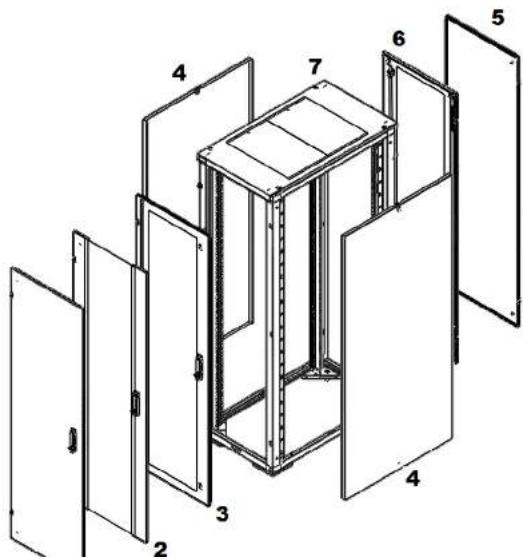
600 WIDE EXPLODED VIEW....4
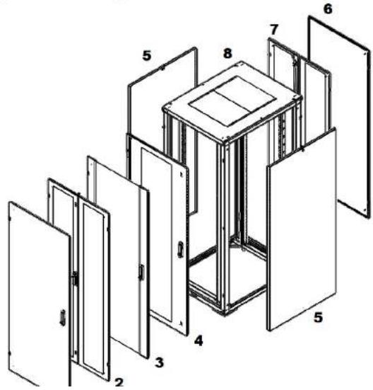
800 WIDE EXPLODED VIEW....5
SWITCHING DOOR HANDING 6
STABILIZING....7
BAYING THE ENCLOSURE....8
SIDE PANEL 9
RACK MOUNT ADJUSTMENT 10
Installation guide
1. SAFETY WARNINGS

This manual contains important instructions that you should follow during installation and maintenance of the RE Series Enclosure. Please read all instructions before operating the equipment and save this manual for future reference.
- WARNING! RE Series enclosure components can be very heavy. It is recommended that several people take part in the unpacking process. When lifting heavy components or electronic equipment, ensure that all safety regulations are observed.
- WARNING! The enclosure must be stabilized before installing any roll-out type accessory, component or electronic device. Failure to stabilize prior to installing equipment may cause the enclosure to tip over.
- WARNING! First, load the heaviest electronic devices and accessories into the bottom of the enclosure to prevent the enclosure from becoming top-heavy.
- WARNING! Never extend more than one roll-out type electronic device or accessory from a stabilized enclosure at a time. Do not sit, stand, or climb on any extended roll-out type electronic device or accessory. Never extend a roll-out type electronic device or accessory component from an enclosure rack that is supported by casters. Doing so may cause a stabilized enclosure rack to tip over.
- WARNING! It is the customer's responsibility to ensure that the floor has a structural load capacity that will safety bear the weight of the RE series Enclosure and installed components.
- WARNING! There must be an uninterruptable safety earth ground from the main power source to the Power Distribution Unit's (PDU) power cord set. Whenever it is likely that ground has been impaired, disconnect the PDU's power cord until the ground has been restored.
Installation guide
- 600 WIDE EXPLODED VIEW
Installation guide
- 800 WIDE EXPLODED VIEW
Installation guide
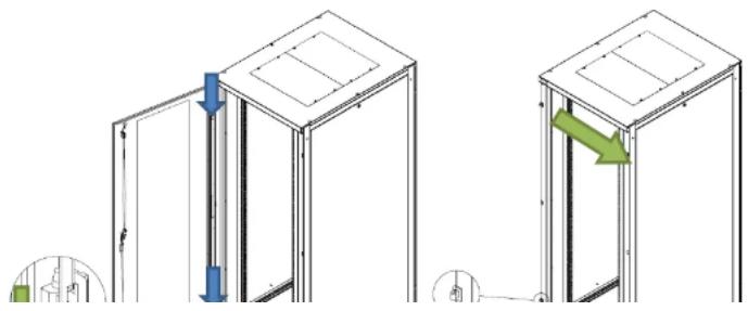
4. SWITCHING DOOR HANDING
- Remove the two hinge pins (Fig 1).
- Remove the hinge section from the enclosure frame (Fig 2).
- Re-install the two hinge sections to the opposite side of enclosure frame (Fig 2).
- Rotate the door 180 degrees.
- Re-install the three hinge pins (Fig 1).
- Loosen the two screws which secure the locking rods (Fig 3).
- Remove the two screws on the back of the door lock and fixing plate (Fig 3).
- Remove and rotate the door handle 180 degrees.
- Replace the fixing plate and two screws (Fig 3).
- Tighten the two screws which secure the locking rods (Fig 3).
natural_image
Technical diagram showing two mechanical assembly steps with arrows indicating movement, no text or symbols present.Installation guide
5. STABILIZING
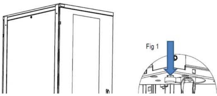
Each enclosure is equipped with four leveling feet (Fig 1).
Use a 13mm spanner to adjust the leveling feet. Ensure that each foot is in firm contact with the floor. Using a level, adjust the leveling feet as required to level the enclosure. For enclosures that have casters, extend the leveling feet so that the casters are approximately 3mm off the floor.
natural_image
Technical line drawing of a door frame with an inset showing a blue arrow labeled 'Fig 1' pointing to a component (no text or symbols on the diagram itself)Installation guide
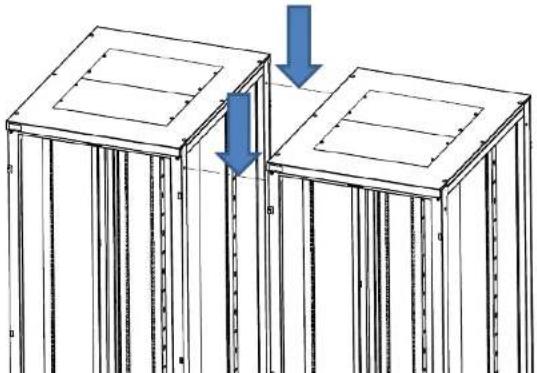
- Remove 4 blanking grommits per enclosure (Fig 1).
- Position and level the adjacent enclosure frames. Ensure that the frames are precisely aligned both vertically and front-to-back.
- Bolt the adjacent frames together with the four nuts and bolts included in the baying kit, part number NRA BTK.
natural_image
Diagram of two identical structural supports with vertical supports and horizontal beams, showing force application arrows (no text or symbols)Installation guide
7. SIDE PANEL
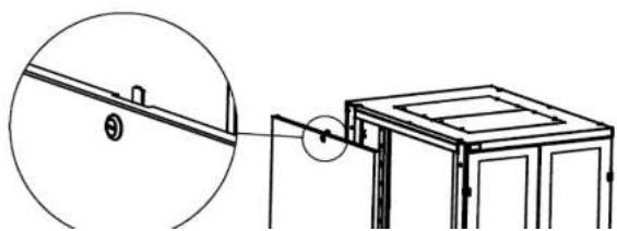
Removal of side panel
- Unlock the side panel with the key supplied (Fig 1).
- Tilt the panel to clear the upper flange
- Lift the panel upwards to clear two locating pins (Fig 2).
Reinstall side panel
- Align the two holes on the bottom of the side panel with the two pins on the enclosure frame. (Fig 2)
- Then lower the side panel on to the pins.
- Lock the side panel with the key supplied (Fig 1).
natural_image
Technical line drawing of a mechanical assembly with a magnified inset showing a detail (no text or symbols)Installation guide
8. RACK MOUNT ADJUSTMENT
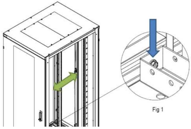
- Loosen the four bolts using a 5mm Allen key, do not remove the bolt (Fig 1).
- Slide rails to desired location.
- Ensuring the rails are vertical, tighten the bolt with 5mm Allen key (Fig 1).
Installation guide
Eaton is dedicated to ensuring that reliable, efficient and safe power is available when it's needed most. With unparalleled knowledge of electrical power management across industries, experts at Eaton deliver customised, integrated solutions to solve our customers' most critical challenges.
Our focus is on delivering the right solution for the application. But, decision makers demand more than just innovative products. They turn to Eaton for an unwavering commitment to personal support that makes customer success a top priority.
For more information, visit www.eaton.eu/electrical
Eaton Industries Manufacturing GmbH
Electrical Sector EMEA
1110 Morges, Switzerland
© Copyright 2012
All rights reserved.
Changes to the products, to the information contained in this document, and to prices are reserved; so are errors and omissions. Only order confirmations and
Brand : EATON
Model : ETN-GD276BAS
Category : Uncategorized