
Joule 570x Developer Kit - Development Kit INTEL - Free user manual and instructions
Find the device manual for free Joule 570x Developer Kit INTEL in PDF.


| Product Type | Developer Kit (Module + Expansion Board) |
| SoC | Intel Atom (specific model not disclosed) |
| Memory | 4 GB LPDDR4 RAM (typical) |
| Storage | 16 GB eMMC (typical) |
| Wireless Connectivity | Intel Dual Band Wireless-AC 8260 (Wi-Fi 802.11ac + Bluetooth 4.2) |
| Module Dimensions | Approx. 50 mm x 35 mm x 5 mm (including thermal shield) |
| Power Input | 12 V DC via barrel jack (CUI PJ-002AH-SMT) |
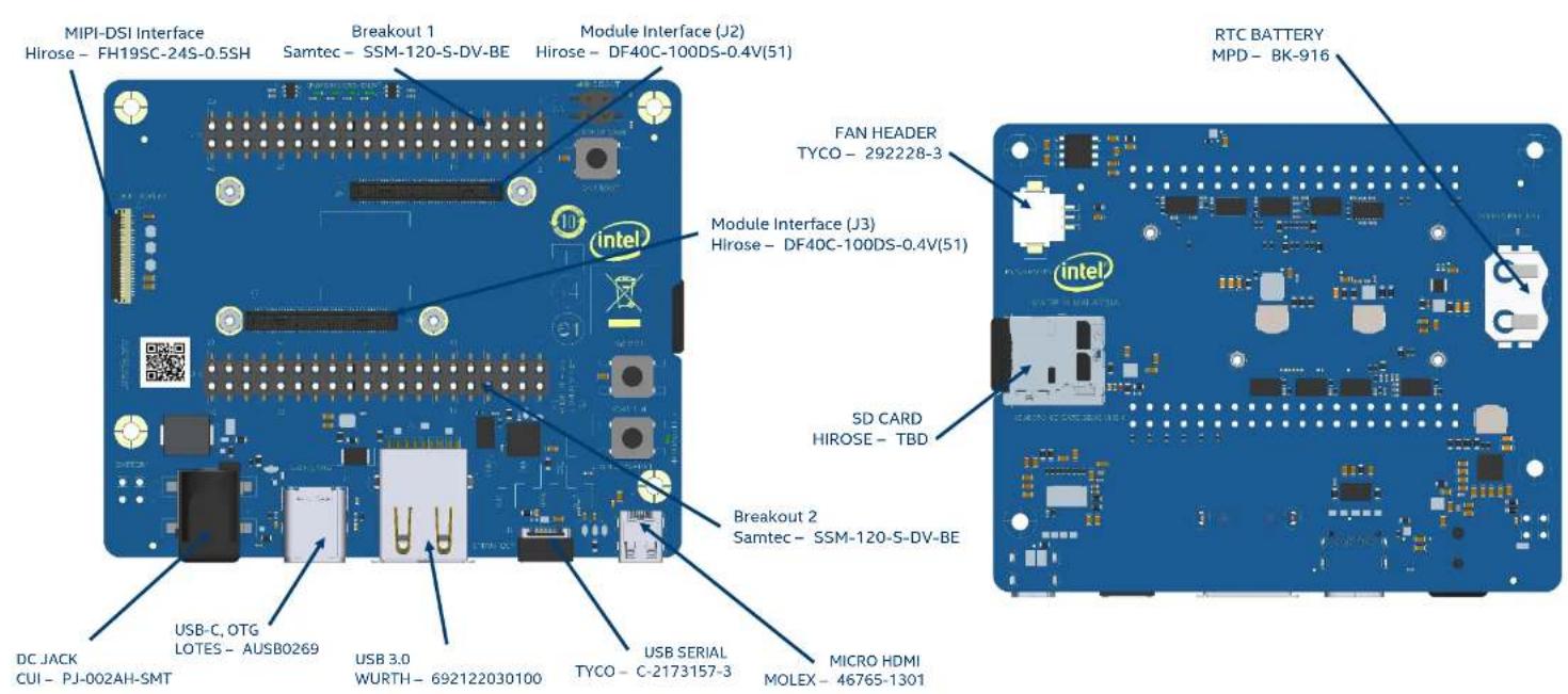
| Display Interface | MIPI-DSI (Hirose FH19SC-24S-0.5SH connector) |
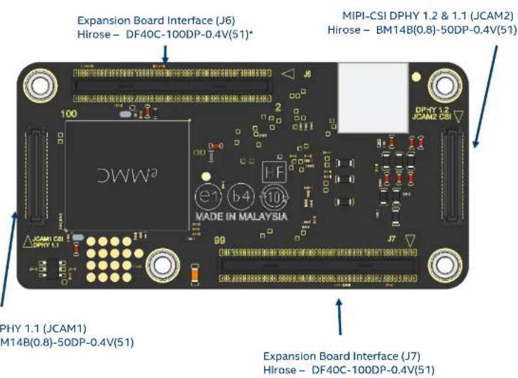
| Camera Interface | 2x MIPI-CSI (Hirose BM14B(0.8)-50DP-0.4V(51) connectors) |
| USB Ports | USB 3.0 (Wurth 692122030100), USB-C OTG (Lotes AUSB0269), USB Serial (Tyco C-2173157-3) |
| Video Output | Micro HDMI (Molex 46765-1301) |
| Expansion Interfaces | 2x 100-pin board-to-board connectors (Hirose DF40C-100DP-0.4V(51)) for expansion board |
| Breakout Connectors | 2x Samtec SSM-120-S-DV-BE (20-pin headers) |
| Additional Features | SD card slot, RTC battery holder (MPD BK-916), 3-pin fan header (Tyco 292228-3) |
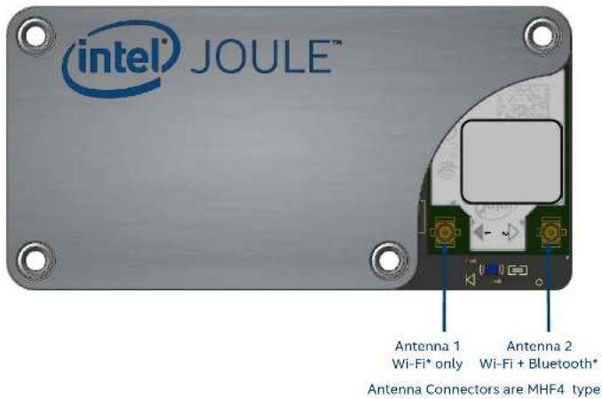
| Antenna Connectors | 2x MHF4 (for Wi-Fi and Bluetooth) |
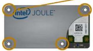
| Installation Method | Module attaches to expansion board via 4x M1.6 screws and 2x 100-pin connectors; audible clicks indicate proper engagement |
| Cooling | Heatsink recommended (reference design available); active fan via header |
| Operating System Support | Linux, Windows IoT Core (from Intel documentation) |
| Intended Use | Prototyping and development for IoT, robotics, computer vision, and edge computing |
| Maintenance and Cleaning | Keep dry and dust-free; clean with a soft, lint-free cloth; avoid liquids and electrostatic discharge |
| Safety Precautions | Do not immerse in water; use only specified power supply; avoid short circuits; handle connectors carefully to prevent wear |
| Spare Parts and Repairability | Module and expansion board are separate; replacement of thermal transfer shield or heatsink possible; connectors have limited life (multiple insertion/removal wears them out) |
Frequently Asked Questions - Joule 570x Developer Kit INTEL
User questions about Joule 570x Developer Kit INTEL
0 question about this device. Answer the ones you know or ask your own.
Ask a new question about this device
Download the instructions for your Development Kit in PDF format for free! Find your manual Joule 570x Developer Kit - INTEL and take your electronic device back in hand. On this page are published all the documents necessary for the use of your device. Joule 570x Developer Kit by INTEL.
USER MANUAL Joule 570x Developer Kit INTEL
INTEL® JOULE™ MODULE PLATFORM MECHANICAL INTERFACE DESCRIPTOR
Document 568978
Revision 1.0
August 2016
Contents:
- General Overview
- Module Mechanical Definition
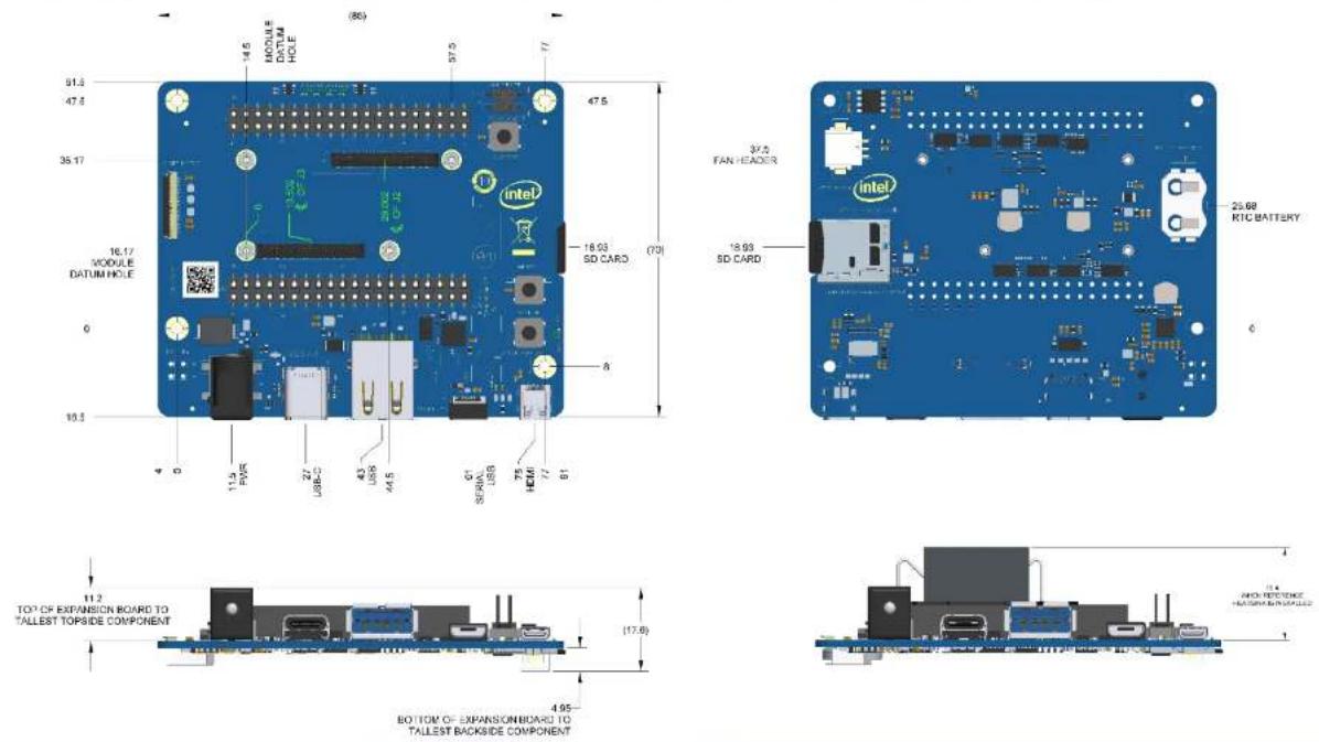
- Expansion Board Mechanical Definition
- Module Installation Recommendation
- Mechanical Attach and Heatsink Reference
SECTION 1
General Overview
1. General Overview
The Intel ^® Joule ^™ Module contains these major components:
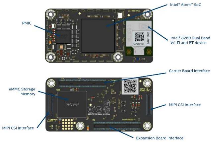
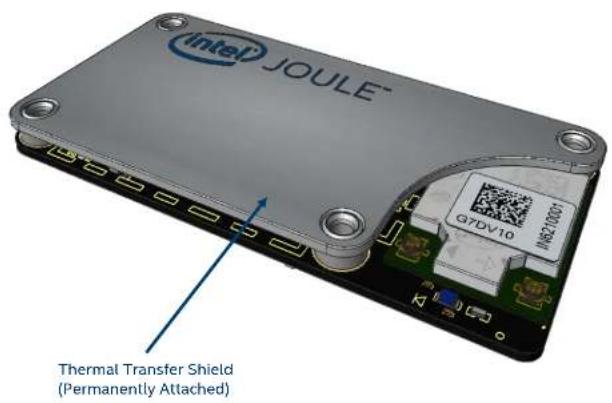
1. General Overview
The Intel ^® Joule ^™ expansion board contains these features that provide access to features of the module.
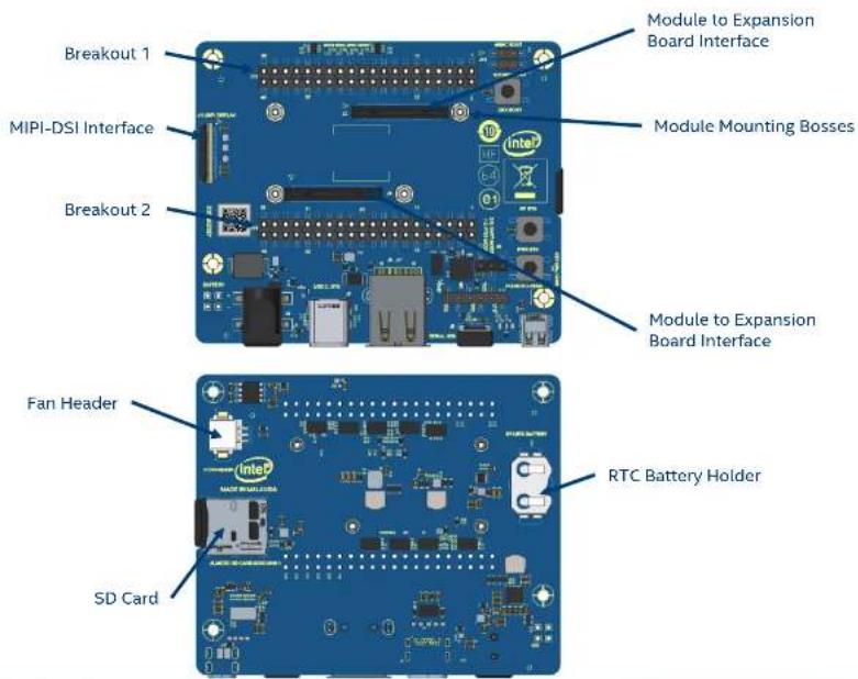
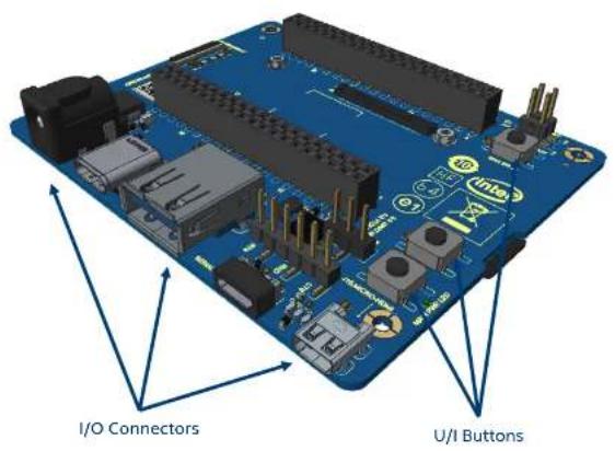
1. General Overview
The Intel ^® Joule ^™ module attaches to the carrier board to create a fully functional compute device.
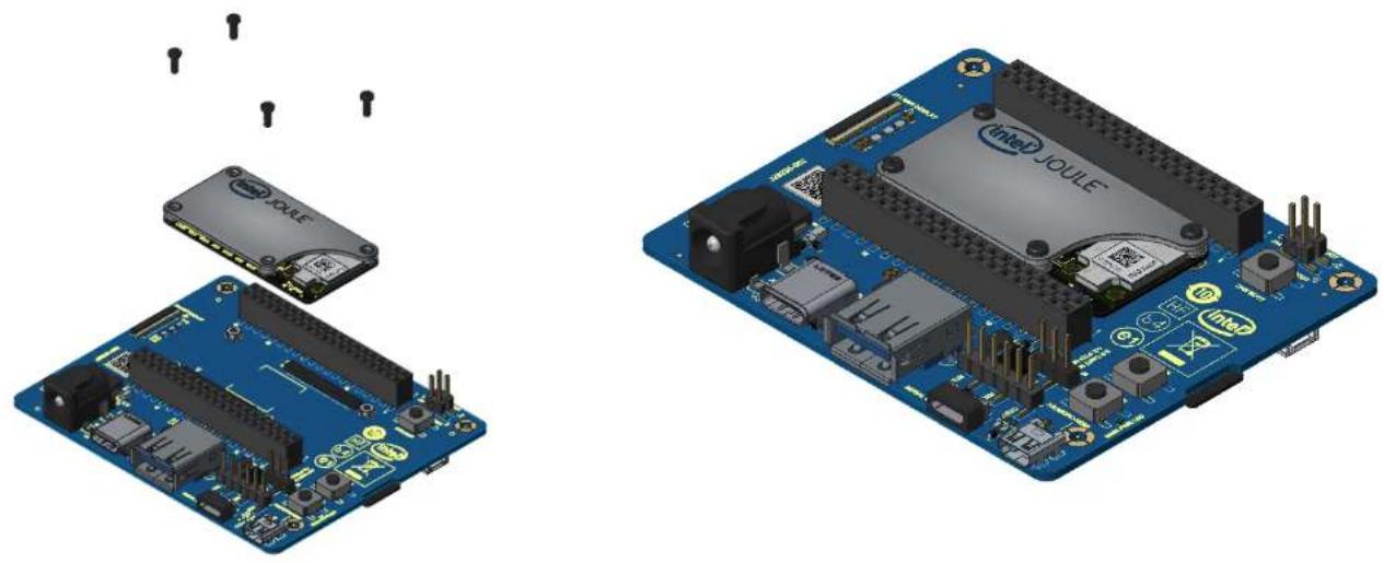
natural_image
Illustration of an Arduino Uno board with various components and connectors, shown from two different angles (no text or symbols present)SECTION 2
Module Mechanical Description
- Module Mechanical Description
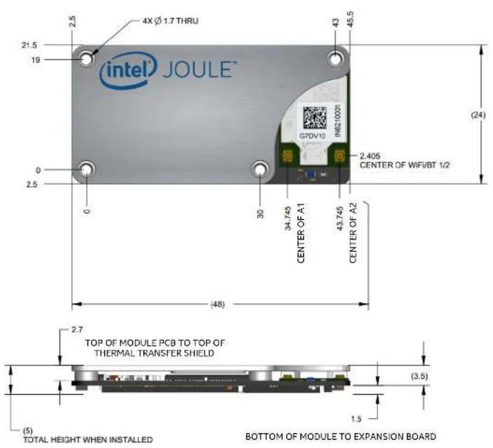
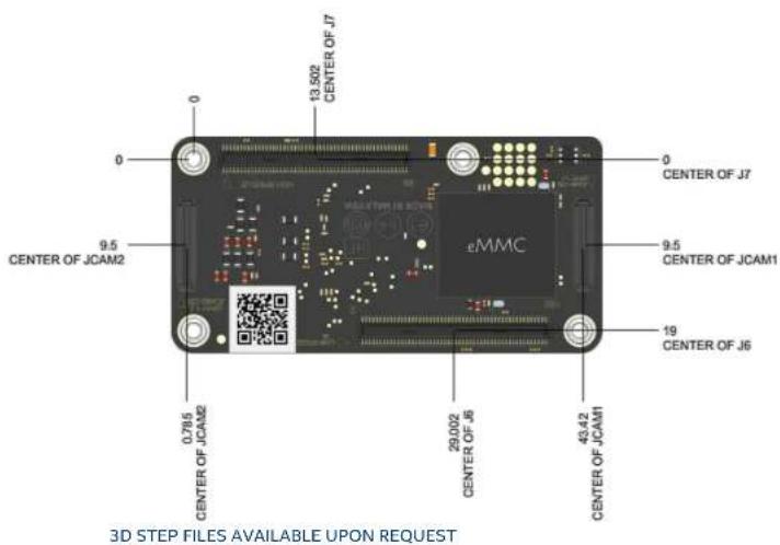
2. Module Interface Connectors
SECTION 3
Expansion Board Mechanical Description
-
Expansion Board Mechanical Description
-
Expansion Board Mechanical Description
SECTION 4
Module Installation Recommendation
4. Module Installation Recommendation
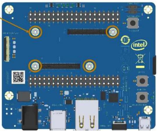
- Visually align the mounting holes of the module with the standoffs on the carrier board
- Lightly set the module in place, on the mating connectors, once all four holes/standoffs are aligned
natural_image
Blue printed circuit board with multiple components and a 'intel' logo (no readable text or symbols beyond branding)NOTE:
• Use caution to minimize damage to the 100p BTB connectors
• Take note that multiple installation and remove will wear out the 100p connectors
4. Module Installation Recommendation
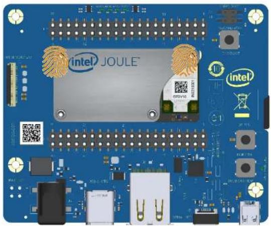
• Using two fingers press evenly on the top two holes of the module
• This will engage the top 100p board to board (BTB) connector
• An audible "click" should be heard

NOTE:
• Use caution to minimize damage to the 100p BTB connectors
• Take note that multiple installation and remove will wear out the 100p connectors
natural_image
Blue printed circuit board with Intel JOULE chip and various electronic components (no readable text or symbols)4. Module Installation Recommendation
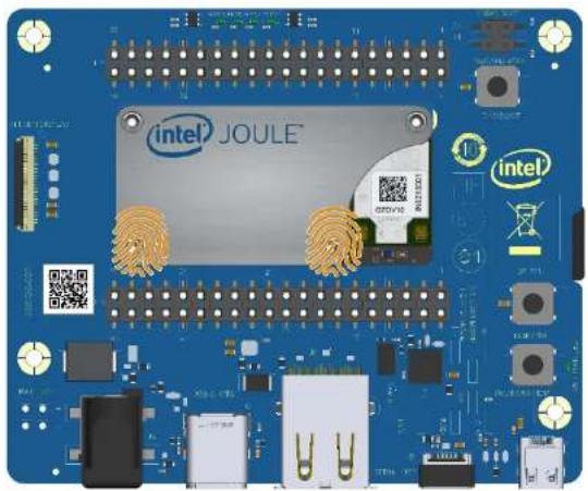
• Using two fingers press evenly on the bottom two holes of the module
• This will engage the bottom 100p board to board (BTB) connector
• An audible "click" should be heard

NOTE:
• Use caution to minimize damage to the 100p BTB connectors
• Take note that multiple installation and remove will wear out the 100p connectors
natural_image
Blue printed circuit board with Intel JOULE chip and various electronic components (no readable text or symbols)SECTION 5
Mechanical Attach and Heatsink References
5. Mechanical Attach Recommendations
Module to expansion board mechanical attach recommendations
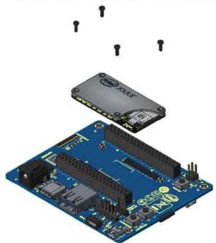
• Electrical connections between the module and carrier board are completed through the twin, 100p board to board connectors
- Mechanical connection is required to be (4) M1.6 screws that pass through the thermal transfer shield (permanently attached to the module) and fasten into the expansion board threaded (SMT) standoffs at \~0.9 in-lbs (\~0.1 N-m) of torque.
natural_image
3D illustration of an Arduino Uno board with visible components and soldered pins (no text or symbols)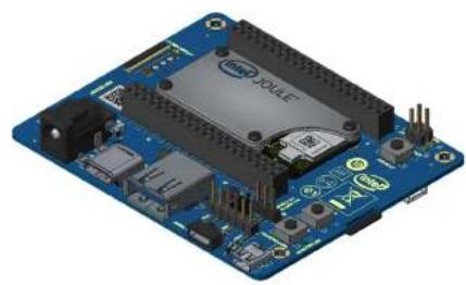
natural_image
Blue electronic circuit board with various components and no visible text or symbols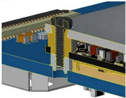
natural_image
Cross-sectional diagram of a mechanical assembly with colored components (no visible text or labels)5. Cooling References
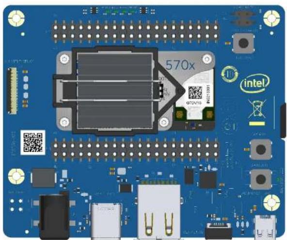
• See the user guide for instructions on installing the reference heatsink (https://software.intel.com/en-us/node/672326)
• See the platform thermal management guide for workloads and module power settings
natural_image
Blue printed circuit board with integrated components and a central chip labeled '570x', featuring Intel branding and no readable text beyond branding elements.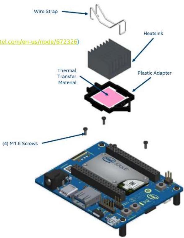

- INTEL® JOULE™ MODULE PLATFORM MECHANICAL INTERFACE DESCRIPTOR
- Contents:
- SECTION 1
- General Overview
- SECTION 2
- Module Interface Connectors
- SECTION 3
- SECTION 4
- Module Installation Recommendation
- NOTE:
- SECTION 5
- Mechanical Attach Recommendations
- Module to expansion board mechanical attach recommendations
- Cooling References
Brand : INTEL
Model : Joule 570x Developer Kit
Category : Development Kit