IPOE-E202 - Wi-Fi repeater Planet - Free user manual and instructions
Find the device manual for free IPOE-E202 Planet in PDF.


| Product Type | Industrial PoE Extender |
| Brand | Planet |
| Model | IPOE-E202 |
| Dimensions (W x D x H) | 199.6 x 81 x 40 mm |
| Weight | 320 g |
| Power Input | IEEE 802.3at PoE+ (up to 30.8W) |
| Power Output (per port) | IEEE 802.3af/at (up to 25W) |
| Number of PoE Output Ports | 2 |
| Operating Temperature | -40°C to 75°C |
| Enclosure | IP63 aluminum case |
| Network Ports | 3 x RJ45 (1 PoE In, 2 PoE Out) |
| Standards | IEEE 802.3af/at, IEEE 802.3ab, 802.3u, 802.3x |
| Switching Capacity | 6 Gbps |
| MAC Address Table | 8K entries |
| Jumbo Frame Support | 9 KB |
| ESD Protection | 2 KV DC |
| EFT Protection | 2 KV DC |
| LED Indicators | PWR, PoE In LNK/ACT, 1000, Budget Alert, PoE Out LNK/ACT, PoE-in-Use |
| Installation | Wall-mount with included kit |
| Waterproof Connectors Provided | Yes (3 x waterproof RJ45 connectors) |
| PoE Budget (max total) | Up to 25W per port, varies with input |
| Regulatory Compliance | FCC Part 15 Class A, CE |
| Maintenance | Keep dry; clean with dry cloth |
| Spare Parts | Waterproof RJ45 connectors available from Planet |
| Safety Warnings | Do not connect non-standard PoE; disconnect if damage occurs |
Frequently Asked Questions - IPOE-E202 Planet
User questions about IPOE-E202 Planet
0 question about this device. Answer the ones you know or ask your own.
Ask a new question about this device
Download the instructions for your Wi-Fi repeater in PDF format for free! Find your manual IPOE-E202 - Planet and take your electronic device back in hand. On this page are published all the documents necessary for the use of your device. IPOE-E202 by Planet.
USER MANUAL IPOE-E202 Planet
Industrial 1-port 802.3at PoE+ to 2-port 802.3af
PoE Extender
IPOE-E202
User's Manual
Trademarks
Copyright © PLANET Technology Corp. 2017.
Contents are subject to revision without prior notice.
PLANET is a registered trademark of PLANET Technology Corp. All other trademarks belong to their respective owners.
Disclaimer
PLANET Technology does not warrant that the hardware will work properly in all environments and applications, and makes no warranty and representation, either implied or expressed, with respect to the quality, performance, merchantability, or fitness for a particular purpose.
PLANET has made every effort to ensure that this User's Manual is accurate; PLANET disclaims liability for any inaccuracies or omissions that may have occurred.
Information in this User's Manual is subject to change without notice and does not represent a commitment on the part of PLANET. PLANET assumes no responsibility for any inaccuracies that may be contained in this User's Manual. PLANET makes no commitment to update or keep current the information in this User's Manual, and reserves the right to make improvements to this User's Manual and/or to the products described in this User's Manual, at any time without notice.
If you find information in this manual that is incorrect, misleading, or incomplete, we would appreciate your comments and suggestions.
FCC Warning
This equipment has been tested and found to comply with the limits for a Class A digital device, pursuant to Part 15 of the FCC Rules. These limits are designed to provide reasonable protection against harmful interference when the equipment is operated in a commercial environment. This equipment generates, uses, and can radiate radio frequency energy and, if not installed and used in accordance with the Instruction manual, may cause harmful interference to radio
communications. Operation of this equipment in a residential area is likely to cause harmful interference in which case the user will be required to correct the interference at his own expense.
CE Mark Warning
This is a Class A product. In a domestic environment, this product may cause radio interference, in which case the user may be required to take adequate measures.
WEEE Warning

To avoid the potential effects on the environment and human health as a result of the presence of hazardous substances in electrical and electronic equipment, end users of electrical
the crossed-out wheeled bin symbol. Do not dispose of WEEE as unsorted municipal waste and have to collect such WEEE separately.
Revision
PLANET Industrial 1-Port 802.3at PoE+ to 2-Port 802.3af PoE Extender User's Manual
For Model: IPOE-E202
Revision: 1.1 (March, 2017)
Part No: EM-IPOE-E202_v1.1 (2350-AF0500-001)
Table of Contents
- Introduction....5
1.1 Package Contents 5
1.2 How to Use This Manual....5
1.3 Product Features.... 5
1.4 Product Specifications 8
1.5 Power over Ethernet Budget....10
1.6 Power over Ethernet Capability 10
1.6.1 When PSE/PoE Switch Output is DC 52V....10
1.6.2 When PSE/PoE Switch Output is DC 56V....11
- Installation 12
2.1 Physical Dimensions....12
2.2 Front Panel 13
2.3 Rear Panel 14
2.4 Mounting Installation....14
2.4.1 Making Waterproof RJ45 Cable 15
2.4.2 Wall Mounting....16
2.4.3 Connecting waterproof RJ45 connector to the IPOE-E202....17
2.5 Connecting IPOE-E202 to Power Source Equipment (PSE) .....19
2.6 Connecting IPOE-E202 to Powered Device (PD)....20
- Customer Support....22
APPENDIX A: Networking Connection....23
A.1 Switch's RJ45 Pin Assignments 23
A.2 RJ45 Cable Pin Assignments....24
1. Introduction
1.1 Package Contents
Check your package for the following parts:
■ Industrial PoE Extender x 1
■ User's Manual x 1
■ Waterproof RJ45 Connector x 3
■ Wall-mounted Kit x 1
If any of these are missing or damaged, please contact your dealer immediately; if possible, retain the carton including the original packing material, and use them again to repack the product in case there is a need to return it to us for repair.
1.2 How to Use This Manual
This Industrial PoE Extender User Manual is structured as follows:
Chapter 2 Installation
The chapter explains the feature, functionality and the physical installation of the Industrial PoE Extender.
Chapter 3 Customer Support
The chapter explains how to get support from PLANET.
Appendix A
This chapter contains cable information of the Industrial PoE Extender.
1.3 Product Features
Physical Port
■ 3-port 10/100/1000BASE-T Gigabit RJ45 interface
◆ 1-port data + power input
◆ 2-port data + power output
Power over Ethernet
■ 1-port data + power input
◆ Complies with IEEE 802.3at Power over Ethernet Plus end span/mid-span PD
◆ Supports PoE input power up to 30.8 watts
■ 2-port data + power output
◆ Complies with IEEE 802.3af/IEEE 802.3at Power over Ethernet/end-span PSE
◆ Up to 2 IEEE 802.3af/802.3at devices powered
◆ Supports PoE power up to 25 watts for each PoE port
◆ Auto detects powered device (PD)
■ Extends the range of PoE to an additional 100 meters (328ft.)
■ Forwards both Ethernet data and PoE power to remote device
Layer 2 Features
■ Hardware based 10/100Mbps, half/full duplex and 1000Mbps full duplex mode, flow control, auto-negotiation and auto MDI/MDI-X
■ Features Store-and-Forward mode with wire-speed filtering and forwarding rates
■ IEEE 802.3x flow control for full duplex operation and back pressure for half duplex operation
■ Integrates address look-up engine, supporting 8K absolute MAC addresses
■ 9K jumbo frame support in 1000Mbps duplex mode
■ Automatic address learning and address aging
■ Supports CSMA/CD protocol
Industrial Case and Installation
■ IP63 aluminum case protection
■ Wall-mount design
■ Waterproof and dustproof
■ Supports EFT protection of 2000 VDC for power line
■ Supports 2000 VDC Ethernet ESD protection
■ -40 to 75 degrees C operating temperature
■ No external power cable required for installation
■ Plug and Play installation
Standard Compliance
■ IEEE 802.3 10BASE-T
■ IEEE 802.3U 100BASE-TX
■ IEEE 802.3ab 1000BASE-T
■ IEEE 802.3x Flow Control
■ IEEE 802.3at Power over Ethernet Plus
■ IEEE 802.3af Power over Ethernet
■ FCC Part 15 Class A, CE

PSE (Power Sourcing Equipment) is a device (switch or hub for instance) that provides power in a PoE setup. Maximum allowed continuous output power per such device in IEEE 802.3af is 15.4W, and in IEEE 802.3at is 30W.
PDs (Powered Devices) like PoE IP phones, PoE IP cameras, PoE wireless access points, etc. are PoE-enabled terminals that consume energy via PSE.
1.4 Product Specifications
| Model IPOE-E202 | |
| Hardware Specifications | |
| Network Connector | PoE In Port1 x 10/100/1000BASE-T Ethernet with High PoE "Data + Power" In, auto MDI/MDI-X, auto-negotiation RJ45 connectorPoE Out Port2 x 10/100/1000BASE-T Ethernet with IEEE 802.3af/at PoE "Data + Power" out, auto MDI/MDI-X, auto-negotiation RJ45 connector |
| Switch Architecture Store | e-and-Forward switch architecture |
| MAC Address Table | 8K MAC address table with auto learning function |
| Data Buffer 1Mbit | |
| Switch Fabric 6Gbps | |
| Switch Throughput 4.46 | Mpps @ 64 bytes |
| Flow Control | IEEE 802.3x pause frame for full duplexBack pressure for half duplex |
| Jumbo Frame 9KB | |
| ESD Protection 2KV DC | |
| EFT Protection 2KV DC | |
| Enclosure IP63 aluminium case | |
| Installation Wall-mount kit | |
| LED Display | System: PWR (Green)PoE Input Port: LNK/ACT (Orange)PoE Input Port: 1000 (Green)Budget Alert (Orange)Per PoE Output Port: LNK/ACT (Green)Per PoE Output Port: PoE-in-Use (Orange) |
| Cable | Twisted-pair cable:10BASE-T: 2-pair UTP Cat. 3, 4, 5 up to 100 meters100BASE-TX: 2-pair UTP Cat. 5, 5e up to 100 meters1000BASE-T: 4-pair UTP Cat. 5e, 6 up to 100 meters |
| Dimensions (W x D x H) | 199.6 x 81 x 40 mm |
| Weight 320g | |
| Power Consumption | 30 watts/102.3BTU (Full loading with PoE function) |
| Power over Ethernet | |
| PoE Standard | PoE In PortIEEE 802.3at Power over Ethernet Plus end-span/mid-span PD class 4 PDPer PoE Out PortIEEE 802.3at Power over Ethernet Plus end-span PSEIEEE 802.3af Power over Ethernet end-span PSE |
| PoE Power | PoE In Port50~57V DC, max. 30.8 wattsPer PoE Out Port44~55V DC, max. 25 watts |
| Power Pin Assignment | PoE In Port 1/2(+), 3/6(-); 4/5(+), 7/8(-) Per PoE Out Port 1/2(+), 3/6(-) |
| Standards Conformance | |
| Regulatory Compliance | FCC Part 15 Class A, CE |
| Stability Testing | IEC 60068-2-32 (Free fail)IEC 60068-2-27 (Shock)IEC 60068-2-6 (Vibration) |
| Standards Compliance | IEEE 802.3 EthernetIEEE 802.3u Fast EthernetIEEE 802.3ab Gigabit EthernetIEEE 802.3x Flow ControlIEEE 802.3af Power over EthernetIEEE 802.3at Power over Ethernet Plus |
| Environment | |
| Operating | Temperature: -40 ~ 75 degrees CRelative Humidity: 5 ~ 95% (non-condensing) |
| Storage | Temperature: -40 ~ 85 degrees CRelative Humidity: 5 ~ 95% (non-condensing) |
1.5 Power over Ethernet Budget
The following table lists how many PoE devices can be powered by IPOE-E202:
| Power Source | PoE Output Budget* | Max. Number of PDs supported | |
| IEEE 802.3af PoE+ PSE | 25 watts max. | Class 4 PD@25 watts | 1 unit |
| Class 3 PD@15 watts | 2 units | ||
| Class 2 PD@7 watts | 2 units | ||
| IEEE 802.3af PoE PSE | 10 watts max. | Class 2 PD@7 watts | 1 unit |

The PoE output budget means the 2-port PD aggregated power output. The aggregated power consumption will be below 30 watts if with PoE+ PSE.
1.6 Power over Ethernet Capability
With different distance and different PoE input source, it will inflect the PoE output capability. Please refer to the table below.

1.6.1 When PSE/PoE Switch Output is DC 52V
| A (Distance) B (Distance) C (Watts) | ||
| 2M 2M 26 | ||
| 2M 20M 25.5 | ||
| 2M 60M 19.6 | ||
| 2M 100M 14.6 | ||
| 20M 2M 25.8 | ||
| 20M 20M 24.8 | ||
| 20M 60M 18 | ||
| 20M 100M 13.2 | ||
| 60M 2M 18 | ||
| 60M 20M 16.7 | ||
| 60M 60M 13 | ||
| 60M 100M 10.3 | ||
| 100M 2M 13.2 | ||
| 100M 20M 12.4 | ||
| 100M 60M 9.8 | ||
| 100M 100M 8.9 | ||
1.6.2 When PSE/PoE Switch Output is DC 56V
| A (Distance) B (Distance) C (Watts) | ||
| 2M 2M 26 | ||
| 2M 20M 25.8 | ||
| 2M 60M 24.7 | ||
| 2M 100M 23.5 | ||
| 20M 2M 25.7 | ||
| 20M 20M 25.4 | ||
| 20M 60M 24.4 | ||
| 20M 100M 22.2 | ||
| 60M 2M 24.5 | ||
| 60M 20M 24.2 | ||
| 60M 60M 21.7 | ||
| 60M 100M 17.5 | ||
| 100M 2M 22.2 | ||
| 100M 20M 20.9 | ||
| 100M 60M 17.2 | ||
| 100M 100M 15.4 | ||

The table list shown here is for your reference only. The actual performance should be related to your environment.
2. Installation
This section describes the functionalities of the industrial PoE extender's components and guides you how to install it. Basic knowledge of networking is assumed. Please read this chapter completely before continuing.
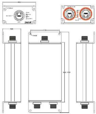
2.1 Physical Dimensions
IPOE-E202 industrial 1-port 802.3at PoE+ to 2-port 802.3af PoE extender dimensions:
(W × D × H): 199.6 × 80 × 40 mm
2.2 Front Panel
Figure 2-1 shows the front panel of Industrial Power over Ethernet extender
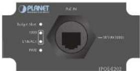
Figure 2-1: IPOE-E202 Front Panel
System
| LED Color Function | |
| PWR Green Lights to indicate the IPOE-E202 has power. |
PoE Input Port
| LED Color Function | ||
| LNK/ACT Orange | Bilinks to indicate that the IPOE-E202 is actively sending or receiving data over that port. | |
| 1000 Green | Lights to indicate the IPOE-E202 is successfully connecting to the network at 1000Mbps. | |
| Off to indicate the IPOE-E202 is successfully connecting to the network at 10Mbps or 100Mbps. | ||
Budget Alert Port
| LED Color Function | ||
| Budget Alert | Orange | Lights to indicate the IPOE-E202 PoE output power is over 20 watts. |
| Off to indicate that the IPOE-E202 PoE output power is not over 20 watts. | ||
2.3 Rear Panel
Figure 2-2 shows the rear panel of Industrial Power over Ethernet extender
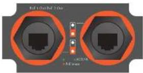
Figure 2-2: IPOE-E202 Rear Panel
PoE Output Port (Port 1 \~ 2)
| LED Color Function | ||
| LNK/ACT Green | Lights to indicate the port is linked up at 10/100/1000Mbps. | |
| Blinks to indicate that the IPOE-E202 is actively sending or receiving data over that port. | ||
| PoE-in-Use Orange | Lights to indicate the port is providing PoE power. | |
| Off to indicate the connected device is not a PoE Powered Device (PD). | ||
2.4 Mounting Installation
This section describes how to install the industrial PoE extender and make connections to it. Please read the following topics and perform the procedures in the order being presented.
2.4.1 Making Waterproof RJ45 Cable
Step 1: Take a waterproof RJ45 jack out from the IPOE-E202 box and prepare one RJ45 cable.

Step 2: Insert the RJ45 cable through the waterproof RJ45 jack.

Step 3: Prepare an RJ45 connector.

Step 4: Put the RJ45 connector in place with cable crimper.

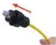
Step 5: To lock in the RJ45 connector, pull back the cable till the connector nicely fit into the waterproof connector hole.

- Use only the waterproof RJ45 connector provided in the package of IPOE-E202.
- If the waterproof RJ45 connector is found missing or damage, please contact your local reseller where you purchased from. If the new waterproof RJ45 connector is obtained from PLANET, make sure its dimensions are the same.
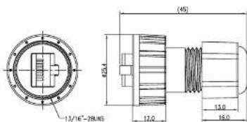
- Never use any waterproof RJ45 connector that is not purchased from PLANET or doesn't have the same dimensions of the IPOE-E202; it will damage the device permanently.
2.4.2 Wall Mounting
To install the Industrial PoE extender on the wall, please follow the instructions described below.
Step 1: Take the four screws from the box.
Step 2: Place the IPOE-E202 on the wall.
Step 3: Use a screwdriver to screw it into the wall.


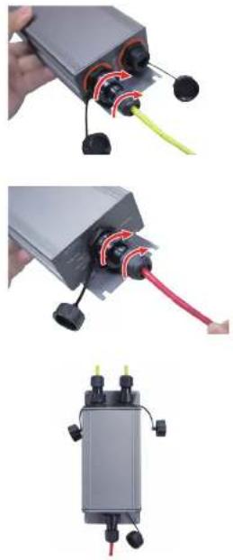
2.4.3 Connecting waterproof RJ45 connector to the IPOE-E202
Step 1: Insert the waterproof RJ45 connector into the port of the IPOE-E202.

Step 2: Turn clockwise to tighten the screw nut.
natural_image
Three-panel image showing a device with cable connectors and red wiring, plus a close-up of its internal components (no visible text or symbols)2.5 Connecting IPOE-E202 to Power Source Equipment (PSE)
This section describes how to install industrial Power over Ethernet extender and make connection to it. Please read the following topics and perform the procedures in the order being presented.
There are 3 RJ45 ports in the industrial Power over Ethernet extender, of which the "PoE IN" port functions as "PoE (Data and Power) Input" and the "PoE-In-Use" port on the other side functions as "PoE (Data and Power) output".
Step 1: Connect a standard Cat5e/6 UTP cable from power source equipment (PSE), such as PoE switch, PoE injector hub and single port PoE injector, to the "PoE IN" port of the IPOE-E202.
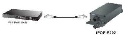
Step 2: The PSE delivers both Ethernet Data and PoE power over UTP cable to the IPOE-E202 and the "PoE IN" LED will be lit steadily.

- When the LED turns steady green, it means the IPOE-E202 is being powered successfully with PoE.
- If the LED is not lit, please check the remote PSE or the cable connecting to a PC or a network device to see if the cable is correct. Or with an 802.3at device such as the target PD, check whether the power injection is correct.
- Never connect any non-standard POE PSE to the IPOE-E202; it will damage the device permanently.
2.6 Connecting IPOE-E202 to Powered Device (PD)
Step 1: Connect the additional Cat5e/6 cable that will be used to connect to the remote Powered Device (PD) to the "PoE-in-Use" port of the IPOE-E202.
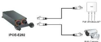
flowchart
graph TD
    A["IPOE-E202"] --> B["Sensor 1"]
    A --> C["Sensor 2"]
    A --> D["Sensor 3"]
    A --> E["Sensor 4"]
    A --> F["PGE Wireless AP"]
    A --> G["PGE Camera"]
Step 2: The "PoE-in-Use" port is also the power injector which transmits DC voltage to the Cat5e/6 cable and transfer data and power simultaneously between the PSE and PD.
Step 3: Once the IPOE-E202 detects the existence of an IEEE 802.3at/af device, the "PoE-In-Use" LED indicator will be lit steadily, showing it is providing power.
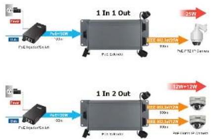
flowchart
graph LR
    A["Power"] --> B["1 In 1 Out"]
    B --> C["I/O Bus"]
    C --> D["25W"]
    E["Power"] --> F["1 In 2 Out"]
    F --> G["I/O Bus"]
    G --> H["12W+12W"]
    I["I/O Bus"] --> J["25W"]
    K["Power"] --> L["1 In 2 Out"]
    L --> M["I/O Bus"]
    M --> N["10W"]
    O["I/O Bus"] --> P["12W+12W"]
    Q["Power"] --> R["1 In 2 Out"]
    R --> S["I/O Bus"]
    S --> T["10W"]

-
If the connected device is not fully complying with IEEE 802.3af/at standard or in-line power device, the PoE-in-Use LED indicator of the IPOE-E202 will not be lit steadily.
-
According to IEEE 802.3af/at standard, the IPOE-E202 will not inject power to the cable if not connected to a standard IEEE 802.3af/at device.
-
DO NOT connect any PSE to port 1 \~ port 2 of the IPOE-E202, it may damage the device permanently.
3. Customer Support
Thank you for purchasing PLANET products. You can browse our online FAQ resource and user's manual on PLANET web site first to check if it could solve your issue. If you need more support information, please contact PLANET switch support team.
PLANET online FAQ:
http://www.planet.com.tw/en/support/faq.php?type=1
Switch support team mail address:
support_switch@planet.com.tw
Copyright ◎ PLANET Technology Corp. 2017.
Contents are subject to revision without prior notice.
PLANET is a registered trademark of PLANET Technology Corp. All other trademarks belong
to their respective owners
APPENDIX A: Networking Connection
A.1 Switch's RJ45 Pin Assignments
1000Mbps, 1000BASE-T
| Contact MDI | MDI-X | |
| 1 BI_DA+ | BI_DB+ | |
| 2 BI_DA- | BI_DB- | |
| 3 BI_DB+ | BI_DA+ | |
| 4 BI_DC+ | BI_DD+ | |
| 5 BI_DC- | BI_DD- | |
| 6 BI_DB- | BI_DA- | |
| 7 BI_DD+ | BI_DC+ | |
| 8 BI_DD- | BI_DC- |
10/100Mbps, 10/100BASE-TX
| R145 Connector pin assignment | ||
| Contact | MDIMedia DependentInterface | MDI-XMedia DependentInterface-Cross |
| 1 Tx + (transmit) Rx + (receive) | ||
| 2 Tx - (transmit) Rx - (receive) | ||
| 3 Rx + (receive) Tx + (transmit) | ||
| 4, 5 | Not used | |
| 6 | Rx - (receive) Tx - (transmit) | |
| 7, 8 | Not used | |
A.2 RJ45 Cable Pin Assignments
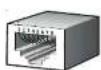
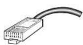
The standard RJ45 reosptacle/connector
There are 8 wires on a standard UTP/STP cable and each wire is color-coded. The following shows the pin allocation and color of straight-through cable and crossover cable connection:
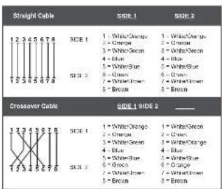
Figure A-1: Straight-through and Crossover Cable
Please make sure your connected cables are with same pin assignment and color as the above picture before deploying the cables into your network.
- Trademarks
- Disclaimer
- FCC Warning
- CE Mark Warning
- WEEE Warning
- Revision
- Table of Contents
- Introduction
- Package Contents
- How to Use This Manual
- Product Features
- Power over Ethernet
- Layer 2 Features
- Industrial Case and Installation
- Standard Compliance
- Power over Ethernet Budget
- Power over Ethernet Capability
- Installation
- Physical Dimensions
- Front Panel
- Rear Panel
- Mounting Installation
- Making Waterproof RJ45 Cable
- Wall Mounting
- Connecting IPOE-E202 to Power Source Equipment (PSE)
- Connecting IPOE-E202 to Powered Device (PD)
- Customer Support
- APPENDIX A: Networking Connection
- A.1 Switch's RJ45 Pin Assignments
- A.2 RJ45 Cable Pin Assignments
Brand : Planet
Model : IPOE-E202
Category : Wi-Fi repeater