
INISOL UNO/1 500 - Central heating boiler DE DIETRICH - Free user manual and instructions
Find the device manual for free INISOL UNO/1 500 DE DIETRICH in PDF.


| Product Type | Solar Domestic Hot Water Tank with Optional Electrical Backup |
| Model | INISOL UNO/1 500 |
| Water Content | 500 L |
| Top Up Volume | 225 L |
| Solar Volume | 275 L |
| Max Operating Pressure (DHW) | 10 bar |
| Solar Exchanger Water Content | 10.3 L |
| Solar Exchanger Surface | 1.5 m² |
| Optional Electrical Backup Output | 4.5 kW |
| Reheating Time (15 to 60°C) | 3 h 05 min |
| Daily Hot Water Volume (night only, 40°C, storage 55°C) | 415 L |
| Daily Hot Water Volume (night+day, 40°C, storage 55°C) | 720 L |
| Cooling Constant Cr (France) | 0.15 Wh/24h·L·K |
| Regulator | Diemasol A Solar Regulator |
| Maintenance | Check magnesium anode every 2 years; descale annually in hard water areas; check pressure (min 0.5 bar) |
| Safety Features | Overheating protection (max collector 130°C, tank 80°C); safety valve; automatic cooling mode |
| Warranty | Contractual guarantee against manufacturing defects; check specific terms for your country |
Frequently Asked Questions - INISOL UNO/1 500 DE DIETRICH
User questions about INISOL UNO/1 500 DE DIETRICH
0 question about this device. Answer the ones you know or ask your own.
Ask a new question about this device
Download the instructions for your Central heating boiler in PDF format for free! Find your manual INISOL UNO/1 500 - DE DIETRICH and take your electronic device back in hand. On this page are published all the documents necessary for the use of your device. INISOL UNO/1 500 by DE DIETRICH.
USER MANUAL INISOL UNO/1 500 DE DIETRICH
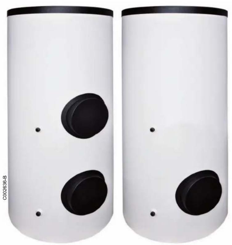
Solar hot water tank
UNO/2 200, 300, 400, 500
UNO/1 200, 300, 400, 500
natural_image
Two white cylindrical speakers with black circular buttons and dot markers, no text or symbols visible
User Guide
Contents
1 Introduction....3
1.1 Symbols and abbreviations ....3
1.2 General....3
1.2.1 Manufacturer's liability 3
1.2.2 Installer's liability ....3
1.2.3 User's liability 3
1.2.4 Compliance of design and manufacture....3
1.2.5 Electrical compliance / Marking C € 4
2 Safety instructions and recommendations....4
2.1 Safety instructions 4
2.2 Recommendations 4
3 Technical description ....5
3.1 Technical specifications ....5
3.1.1 Double coil hot water tank: UNO/2 5
3.1.2 Electro-solar hot water tank: UNO/1....6
3.2 Main parts....8
4 Setting the DHW tank outlet temperature 9
4.1 Programming and setting the electrical back-up....9
4.2 Setting the thermostatic mixing valve....9
5 Diemasol A solar regulator....10
5.1 General description of how the unit operates....10
5.2 Start-up....10
5.3 Adjustment keys 11
5.4 LED message code 11
5.5 Measured values and adjustment parameters....12
6 Checking and maintenance ....16
6.1 Solar installation 16
6.2 Tank 16
6.2.1 Magnesium anodes 16
6.2.2 Safety valve or safety unit 16
6.2.3 Descaling 16
6.2.4 Casing 16
6.2.5 Vent device 16
6.3 Solar circuit....16
Warranty certificate....18
1.1 Symbols and abbreviations
In these instructions, various markings and pictograms are used to draw your attention to particular information. In so doing, De Dietrich Thermique S.A.S wishes to safeguard the user's safety, obviate hazards and guarantee correct operation of the appliance.

Danger
Risk of a dangerous situation causing serious physical injury.

Warning
Risk of a dangerous situation causing slight physical injury.
1.2 General
Congratulations on choosing a De Dietrich product, a product of quality. We strongly recommend that you read the following instructions in order to guarantee the optimal operation of your appliance. We are sure that you will not be disappointed and that it will satisfy all of your expectations.
1.2.1 Manufacturer's liability
Our products are manufactured in compliance with the requirements of the various applicable European Directives. They are therefore delivered with C€ marking and all relevant documentation.
In the interest of customers, we are continuously endeavouring to make improvements in product quality. All the specifications stated in this document are therefore subject to change without notice.
1.2.2 Installer's liability
The installer is responsible for the installation and initial start up of the appliance. The installer must respect the following instructions:
Read and follow the instructions given in the manuals provided with the appliance.
Carry out installation in compliance with the prevailing legislation and standards.
1.2.3 User's liability
To ensure the optimum operation of your appliance, we strongly recommend that you abide by the following instructions:
Read and follow the instructions given in the manuals provided with the appliance.
▶ Call on qualified professionals to carry out installation and initial start up.
1.2.4 Compliance of design and manufacture
This product conforms to the requirements of european directive 97 / 23 / EC, article 3, paragraph 3, on pressure equipment.

Caution
Risk of material damage.

Specific information.
Reference
Refer to another manual or other pages in this instruction manual.
▶ DHW: Domestic hot water.
Our liability as the manufacturer may not be invoked in the following cases:
▶ Failure to abide by the instructions on using the appliance.
▶ Faulty or insufficient maintenance of the appliance.
▶ Failure to abide by the instructions on installing the appliance.
▶ Perform the initial start up and carry out any checks necessary.
Explain the installation to the user.
If a maintenance is necessary, warn the user of the obligation to check the appliance and maintain it in good working order.
▶ Give all the instruction manuals to the user.
▶ Get your installer to explain your installation to you.
To carry out inspections and maintenance required by a qualified professional.
- Keep the instruction manuals in good condition close to the appliance.
1.2.5 Electrical compliance / Marking C€
This product complies to the requirements to the european directives and following standards:
• 2006/95/EC Low Voltage Directive
Reference Standard: EN 60.335.1.
• 2004/108/EC Electromagnetic Compatibility Directive Reference Standards: EN 50.081.1 / EN 50.082.1 / EN 55.014.
2 Safety instructions and recommendations
2.1 Safety instructions

Any work on the installation must be done by a qualified professional in compliance with the codes of practice and according to the instructions provided.
2.2 Recommendations
Have the installation regularly serviced to guarantee that it operates correctly over time.
It is essential to check the magnesium anode in the DHW tank and the installation and heat transporting fluid pressure every two years.

Never cut the power to the solar control system, even during extended absences. The control system protects the installation against overheating in summer when it is running.
During extended absences, we recommend lowering the set point temperature in the solar DHW tank to 50^ C. When the user is present, the set point must be set to 60^ C.

Never drain the installation. Do not replace or add water or solar fluid to the installation. These actions must be carried out by a qualified technician.

Do not modify the control system parameters unless fully conversant with them.
3 Technical description
3.1 Technical specifications
3.1.1 Double coil hot water tank: UNO/2 ...
| UNO/2 200 UNO/2 300 UNO/2 400 UNO/2 500 | |||||
| Water content | litres 200 300 395 500 | ||||
| Top up volume | litres 95 105 165 180 | ||||
| Solar volume | litres 105 195 230 320 | ||||
| Max operating pressure, DHW | b | a | r | 1 | 0 |
| Boiler heat exchanger | |||||
| Maximum operating temperature | °C 90 90 90 90 | ||||
| Maximum operating pressure | b | a | r | 1 | 0 |
| Water content | litres 3.5 4.3 | 4.9 | 4.9 | ||
| Exchange surface | m^2 | 0.52 | 0.65 | 0.72 | 0.72 |
| Pressure drop | kPa | 3.0 | 3.0 3.4 | 3.4 | |
| Solar exchanger | |||||
| Water content | litres 3.8 | 8.1 8.1 | 10.3 | ||
| Exchange surface | m^2 | 0.75 1.2 | 1.2 1.5 | ||
| Performance | |||||
| Primary temperature at 70 °C | |||||
| Power exchanged(1)(3) | kW | 13.5 | 16 | 17.5 | 17.5 |
| Flow per hour(1)(3) | l/h | 330 390 430 430 | |||
| Primary temperature at 80 °C | |||||
| Power exchanged(1)(3) | k | W | 1 | 7 | 5 |
| Flow per hour(1)(3) | l/h | 430 515 565 565 | |||
| Flow in 10 minutes(2)(3) | l/10 mm | 170 190 305 325 | |||
| Primary temperature at 90 °C | |||||
| Power exchanged(1)(3) | kW | 22 26 29 29 | |||
| Flow per hour(1)(3) | l/h | 540 640 712 712 | |||
| Cooling constant Cr * | Wh/24h·L·K | 0.20 | 0.20 | 0.19 | 0.15 |
* Only in France / Test conducted in accordance with the standard NF D 30-003
(1) Domestic cold water inlet 10 °C - Domestic hot water outlet 45 °C - Primary flow rate 2 m³/h
(2) Domestic cold water inlet 10 °C - Domestic hot water outlet 40 °C - Domestic hot water storage temperature 65 °C - Primary flow rate 2 m³/h
(3) Values measured only on the back-up volume
3.1.2 Electro-solar hot water tank: UNO/1 ...
| UNO/1 200 | UNO/1 300 | UNO/1 400 | UNO/1 500 | ||
| Water content | litres 200 300 395 500 | ||||
| Top up volume | litres 100 145 185 225 | ||||
| Solar volume | litres 100 155 210 275 | ||||
| Max operating pressure, DHW | b | a | r | 1 | 0 |
| Solar exchanger | |||||
| Water content | litres 3.8 8.1 8.1 10.3 | ||||
| Exchange surface | m^2 | 0.75 1.2 12 1.5 | |||
| Cooling constant Cr * | Wh/24h L K 0.23 0.20 0.19 0.15 | ||||
| Optional electrical back-up | |||||
| Output of the electrical back-up | kW 2.2 3.0 4.5 4.5 | ||||
| Reheating time from 15 to 60°C | 2 h 50 min 3 h 00 min 2 h 30 min 3 h 05 min | ||||
| VDHW 40 night(1)(3)Domestic hot water storage temperature: 55 °C | litres 160 225 300 415 | ||||
| VDHW 40 night + day(2)(3)Domestic hot water storage temperature: 55 °C | litres 310 425 590 720 | ||||
| VDHW 40 night(1)(3)Domestic hot water storage temperature: 60 °C | litres 185 260 345 | ||||
| VDHW 40 night + day(2)(3)Domestic hot water storage temperature: 60 °C | litres 330 460 650 | ||||
* Only in France / Test conducted in accordance with the standard NF D 30-003
(1) Daily water volume at 40^ C on night heating only
Domestic cold water inlet 15^ C
(2) Daily water volume at 40^ C on night heating + 2 hours on day
Domestic cold water inlet 15^ C
(3) Values measured only on the back-up volume
■ Composition of the NF CESI INISOL UNO solar systems packages (for France only)
Check the composition of the CESI solar system, which complies with the requirements of the NF CESI mark, using the table below. The references and packages listed must be shown on the invoice for the system sold by the installer.
A system is complete and functional according to the NF CESI mark if all system references appear on the invoice.
The system is composed of the following elements:
- A collector field with 1, 2 or 3 solar collectors.
- A solar domestic hot water tank to which a solar station incorporating a heating pump, an expansion vessel and a Diemasol A control system is to be mounted.
- The solar fluid that protects the installation from frost and corrosion.
The system is delivered to the installer in two units: a roof pack containing the collectors, their mounting system and the hydraulic connections on the one hand, and a cellar pack containing the calorifier, the system components and the solar fluid on the other hand.
| CESI System | Array of collectors | Domestic hot water production | Solar fluid | |||||
| Number of panels | Type of mounting | package / Reference | DHW calorifier type | package / Reference | Volume (litres) | Back-up type | package / Reference | |
| INISOL UNO/2 200-2 | 1 | O | ER 152100014074 | r | o | f | EG 10189807794 | |
| 1 | Roof-integral Installation (>20°) | ER 153100014075 | UNO/2 200 | ER 148100014069 | 200 Boiler | |||
| 1 | Roof-integral Installation (17°) | ER 230100014740 | ||||||
| INISOL UNO/2 200-4 | 2 | O | ER 154100014076 | r | o | f | EG 10189807794 | |
| 2 | Roof-integral Installation (>20°) | ER 155100014077 | UNO/2 200 | ER 148100014069 | 200 Boiler | |||
| 2 | Roof-integral Installation (17°) | ER 231100014741 | ||||||
| INISOL UNO/2 300-4 | 2 | O | ER 154100014076 | r | o | f | EG 10189807794 | |
| 2 | Roof-integral Installation (>20°) | ER 155100014077 | UNO/2 300 | ER 149100014070 | 300 Boiler | |||
| 2 | Roof-integral Installation (17°) | ER 231100014741 | ||||||
| INISOL UNO/2 300-4 (Full package) | 2 | O | ER 140100014061 | r | o | f | Included in the full package | |
| 2 | Roof-integral Installation (>20°) | ER 142100014063 | UNO/2 300 | Included in the full package | 300 Boiler | |||
| INISOL UNO/2 300-6 | 3 | O | ER 156100014078 | r | o | f | EG 10189807794 | |
| 3 | Roof-integral Installation (>20°) | ER 157100014079 | UNO/2 300 | ER 149100014070 | 300 Boiler | |||
| 3 | Roof-integral Installation (17°) | ER 232100014742 | ||||||
| INISOL UNO/2 400-4 | 2 | O | n_1 ER 154100014076 | r | o | f | EG 10189807794 | |
| 2 | Roof-integral Installation (>20°) | ER 155100014077 | UNO/2 400 | 400 Boiler | ||||
| 2 | Roof-integral Installation (17°) | ER 231100014741 | ||||||
| INISOL UNO/2 400-6 | 3 | O | n_1 ER 156100014078 | r | o | f | EG 10189807794 | |
| 3 | Roof-integral Installation (>20°) | ER 157100014079 | UNO/2 400 | 400 Boiler | ||||
| 3 | Roof-integral Installation (17°) | ER 232100014742 | ||||||
3.2 Main parts
■ Solar hot water tank
- Tank in enamelled steel
- Solar coil
- Insulation in CFC-free polyurethane foam
- External PVC casing - white
■ Solar station
The solar heating pump unit comprises the solar circuit safety unit, a pressure and temperature gauge and a flowmeter to visualise circulation of the solar fluid between the panels and the DHW tank. An expansion vessel is connected to the solar unit; it is used to compensate for the expansion of the solar fluid in which the temperature varies between 0 and 150°C.
■ Diemasol A regulator
The control system is the solar system's brain; it makes the solar heating pump run at variable speeds according to the difference in temperature between the bottom of the DHW tank and the solar panels. The control system manages the set point temperature (temperature to be attained in the DHW tank), overheating and nighttime cooling. The control system also displays the various operating modes, the temperatures in the collectors and in the bottom of the DHW tank, as well as signalling any malfunctions.
4 Setting the DHW tank outlet temperature
4.1 Programming and setting the electrical back-up
The temperature of the volume of water heated by the electrical resistor is set by the installer on commissioning of the installation according to the size of the home.
Using the programming device installed in the electrical panel, it is possible to adjust the volume of water heated to 40^ C by the resistor in two ways:
By forcing continuous heating by the resistor (off-peak hours contact) for significant unforeseen needs.
By programming the heating time outside off-peak periods (2 hours maximum according to the DHW volume at 40°C required) to compensate for the lack of sunshine in winter, for example. The programmed period outside off-peak hours must preferably be between 12 h and 18 h.
4.2 Setting the thermostatic mixing valve
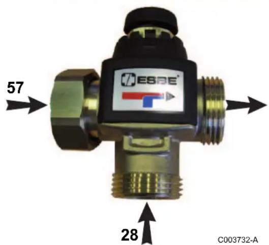
- Domestic cold water inlet
- DHW tank domestic hot water outlet
The mixing valve is set in the factory for a DHW outlet temperature of 60^ C (position 6). To lower this temperature, remove the top cover and turn the wheel anti-clockwise. In position 1, the outlet temperature is lowered to 35^ C.
5 Diemasol A solar regulator
5.1 General description of how the unit operates
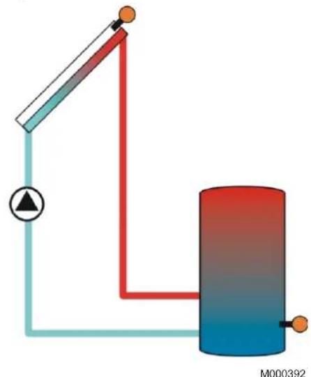
In automatic mode, the Diemasol A regulator operates in accordance with the following principles:
The sun's rays heat the transfer fluid in the collector. For the regulation process to be triggered, a minimum temperature of 30 °C is required in the collector and there must be a temperature difference of 10 K by comparison with the tank.
During the AUTO-calibration stage which follows (tu parameter setting tu, factory setting 1 minute) the PUMPE (relay) operates to its full extent (100%).
Subsequently, the solar pump regime is calculated dynamically depending on a difference between the reference temperature (parameter DT, factory setting 20 K) and the calorifier temperature.
Depending on the heat available, the system heats up the solar tank and cuts off when the tank storage temperature is reached (adjustment parameter SX, factory setting: 60 °C).
When the temperature in the collectors reaches the maximum value (adjustment parameter CX, factory setting 100°C), the solar pump is triggered to cool the collectors. The pump continues to operate until the temperature in the collectors is lower than 5 K at parameter CX and/or the maximum storage temperature (80°C) is reached in the hot water storage tank. Regulation goes into cooling mode if the preparer tank temperature is exceeded. As soon as the temperature in the collectors drops below the temperature in the calorifier, the calorifier is cooled down to its set temperature. The installation is thus protected against overheating and repeated stoppages, allowing thus the prolonged absence of the user even in the summer period.
natural_image
Pure electrical circuit lines without any symbols5.2 Start-up

If the temperature in the solar collectors is higher than 130^ C, the control system operates in safety mode. Wait until the evening before start-up or cool down (cover) the solar collectors.
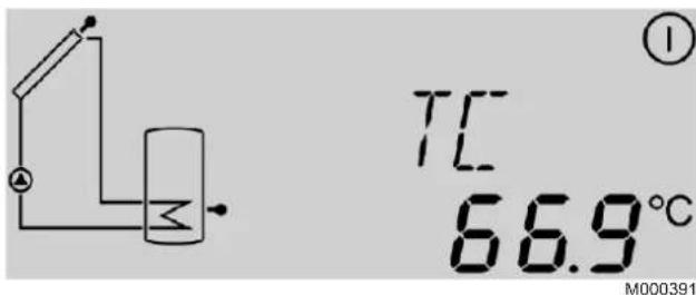
Switch on the device. The regulator starts an initialisation phase during which the LED flashes red and green. When initialisation is complete, the regulator changes to automatic mode. The factory settings for this mode give optimum performance with most installations.
If special conditions make it necessary to change the settings, the corresponding adjustment parameters can be reset.
5.3 Adjustment keys
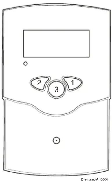
The regulator is controlled by the 3 keys only located below the display.
The right-hand key (1) takes you to the next menu or increases the adjustment values.
The left-hand key (2) does the opposite.
The adjustment parameters are displayed after the measured values. To access these parameters, press and hold the right-hand key for 2 sec. from parameter TC. When the display shows an adjustment parameter, the word SET appears. To set the value displayed, press the middle button 3.
- Select the required parameter using keys 1 and 2.
- Press the 3 key: The word SET flashes.
- Adjust the value using keys 1 and 2.
- Press the 3 key: The set value is stored. The word SET stops flashing.
5.4 LED message code
■ Continuously green
PUMPE relay is closed.
Regulation operating normally (System Operating). Solar system Operating. The temperature of the hot water tank (parameter TS) increases.
■ Continuously red
PUMPE relay is open.
The installation is stopped. The solar collectors are not hot enough (parameter TC) to enable operation.
■ Flashing green/red
- Initialisation phase
- Sensor fault. See chapter Sensor fault.
- The installation is in manual mode. Set the regulator to automatic mode.
- Maximum tank temperature exceeded. The hot water tank has reached the set temperature and the installation is in overheating safety mode or in cooling mode.
- Maximum temperature of the solar collectors exceeded. The installation is in safety mode. It remains in this mode until the temperature of the solar collectors has fallen back below the maximum temperature.
5.5 Measured values and adjustment parameters
| Channel | Abbreviation | Range | Increment | Factory setting |
| Collector temperature | TC [-50.0 ... 250.0] °C -- | |||
| Tank temperature | TS [-50.0 ... 250.0] °C -- | |||
| Amount of heat | kWh [0 ... 9999] kWh -- | |||
| Pump regime | PC [0 ... 100] % -- | |||
| Self-calibration time | tc | [0 ... 5] minutes | -- | |
| Reference temperature difference | DT | [10 ... 20] K | 0.1 | 20 |
| Set temperature of the solar calorifier | SX | [20 ... 80] °C | 0.1 | 60 |
| Maximum collector temperature | CX | [100 ... 125] °C | 0.1 | 100 °C |
| Self-calibration phase | tu | [1 ... 5] minutes | 1 | 1 |
| Pump minimum speed | PN | [50 ... 100] % | 5 | 50 |
| Tubular solar collector function | FT | [0 ... 1] | 1 | 0 |
| Maximum flow rate | Fx | [0 ... 20] l/min | 0.1 | 6.7 |
| Manual mode | MM | [0 ... 2] | 1 | 2 |
*with S3 sensor only (optional)

Measured values
Adjustment parameter
i The regulator has a safety system that cuts off the tank at temperatures of over 80^ C.
■ Measured value TC - Collector temperature
The value TC shows the temperature in ^ C given by the collector sensor in real time.
■ Measured value TS - DHW sensor temperature
The value TS shows the temperature in ^ C given by the tank sensor in real time
■ Measured value kWh - Amount of heat
The value kWh shows in kWh the total amount of heat produced by the installation since the regulator was put into service.
i The quantity of heat (kWh value) can only be used for checks carried out for personal reasons.
■ Measured value tc - Self-calibration time
The value tc shows the self-calibration phase time remaining in seconds. During the self-calibration phase, the pump operates at full speed (100 %); its speed is only controlled after the self-calibration phase.
■ Adjustment parameter DT - Reference temperature difference
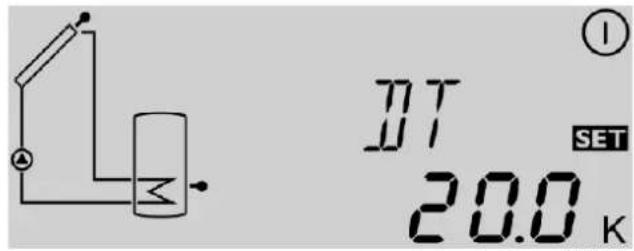
Adjustment range: 10 ... 20 K
Factory setting: 20 K
i Switching-on difference: Non-adjustable value 10 K
Switching-off difference: Non-adjustable value 5 K
The regulator reads the temperatures measured by sensors S1 (TC) and S2 (TS) and compares the resulting temperature difference with the switching-on difference which is preset to 10 K. Regulation is activated when the temperature difference T is equal to or greater than the preset value. The display shows The LED changes to green. When the value falls below the preset 5 K switching-off difference, the regulator switches off. The regulator tries to achieve a temperature difference of 20 K (factory setting) between the collector and the tank to produce high temperature hot water as rapidly as possible. To do this, it uses dynamic speed control.
■ Adjustment parameter SX - Set temperature of the solar calorifier
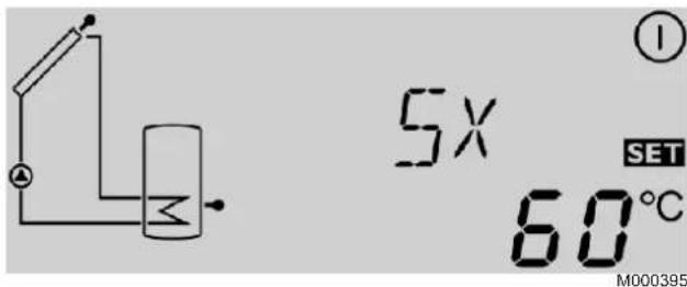
Adjustment range: 20 ... 80 °C
Factory setting: 60 °C
i Maximum tank temperature (emergency cut-off): Non-adjustable value 80 °C
The set temperature Sx is the desired temperature for the solar calorifier.
If the maximum tank temperature is exceeded, tank heating is interrupted to prevent damage due to overheating. The display shows and (flashing) and the LED changes to flashing red/green.
The higher the set temperature for the calorifier, the greater the energy stored. Setting to 60 ... 75°C is suitable for normal use with daily draw-offs.
In the event of prolonged absences (weekend, holidays):
- Reduce the calorifier temperature to 50°C
- Turn off the back-up (boiler or electrical resistance)
The installation is thus protected against overheating and the longevity of the heat conducting fluid is conserved.
■ Adjustment parameter CX - Maximum collector temperature
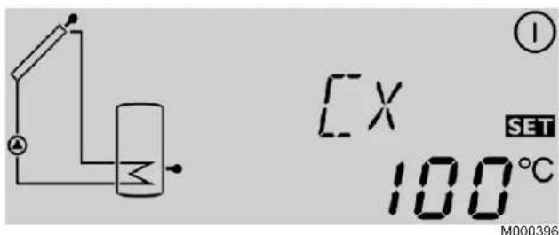
Adjustment range: 100 ... 125 °C
Factory setting: 100 °C
i Maximum collector temperature (overheating safety): Non-adjustable value: 130 °C.
If the temperature in the collector rises above its maximum temperature CX even though the solar circuit is stopped (tank set storage temperature reached), the solar pump (R1) switches on and cools the collector (system cooling). In these conditions, the tank temperature rises, but it can't exceed 80 °C (safety cut-off).
If the calorifier reaches the maximum temperature of 80^ C (safety shutdown), the regulator switches off the solar pump.
i The collectors may reach a temperature of 160 ... 200°C, which is normal for a solar installation.
The cooling functions allows heat to dissipate; the system thus remains operational longer during hot summers. When it leaves the factory, the collector's maximum temperature is preset to 100 °C; however, it is possible to change this within the range 100 ... 125 °C. If the maximum collector temperature is exceeded, the display shows
①, and (flashing) and the LED changes to flashing red/green.
■ Adjustment parameter tu - Self-calibration phase
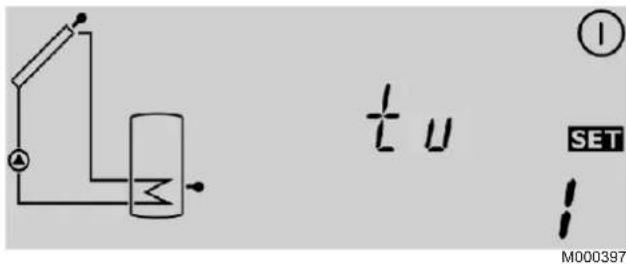
Adjustment range: 1 ... 5 minutes
Factory setting: 1 minutes
When the solar collector reaches a minimum temperature of 30 °C and a preset temperature difference of 10 K from the tank temperature, the regulator switches on the solar circulating pump at full speed for the time period set by parameter tu. During this phase, any air bubbles present in the solar collectors or the pipes are moved to the complete solar station by the high circulation speed in the pipes and eliminated by the Airstop system (manual bleed degasser). After this phase, the regulator changes to "matched flow" mode. The remaining self-calibration time is displayed with parameter tc.
■ Adjustment parameter PN - Pump minimum speed
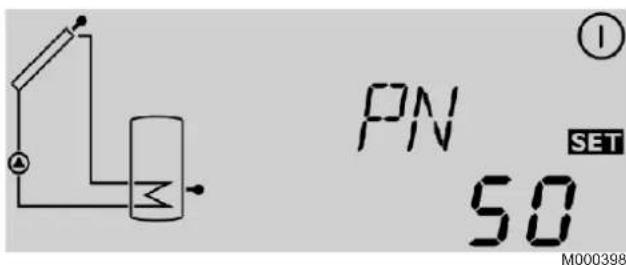
Adjustment range: 50 ... 100%
Factory setting: 50%
Adjustment parameter PN sets a minimum value for the solar pump speed at the relay R1 output. The lower the pump regime, the lower its flow.
■ Adjustment parameter FT - Tubular solar collector function
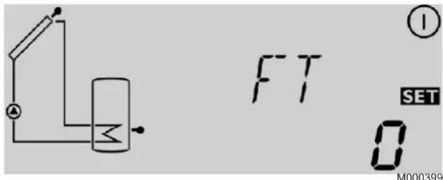
Adjustment range: 0/1
Factory setting: 0
0: no
1: yes
If the regulator detects a temperature rise in the collector of 2 K compared to the last measurement, the solar pump runs at full speed for 30 seconds to measure the current average temperature.
The measured temperature thus becomes the new reference temperature.
If the measured temperature (new reference) then increases again by 2 K, the solar pump starts again for 30 seconds.
The regulator switches automatically to solar heating mode if the temperature difference between the collector and the tank exceeds the switching-on temperature difference when the solar pump is operating or the system is stopped.
If the collector temperature falls by 2 K while the system is stopped, the tubular solar collector activation temperature is rechecked.
| Tubular solar panels | ||
| Number of panels | Flow rate l/h | Flow rate l/min |
| minimum: 1x4 820 13.7 | ||
| 1x5 750 12.5 | ||
| 1x6 680 11.4 | ||
■ Adjustment parameter MM - Operating mode
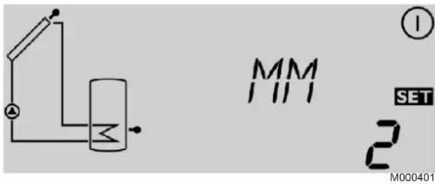
Adjustment range: 0 ... 2
Factory setting: 2
For inspection and maintenance work, it is possible to operate the regulator in manual mode. To operate the regulator in manual mode, it is necessary to input parameter MM from the following table.
| MM R1 | LED | |
| 0 Open | Flashing green/red | |
| 1 Closed | Flashing green/red | |
| 2 | automatic | automatic |
■ Adjustment parameter Fx - Maximum flow rate
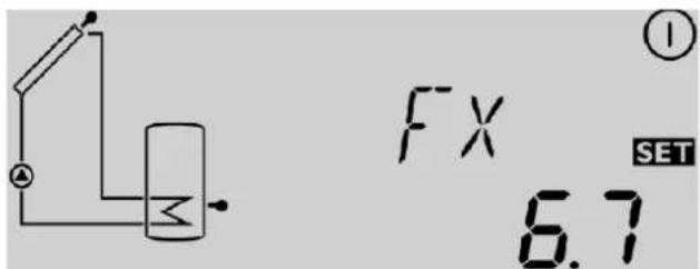
Adjustment range: 0 ... 20 l/min
Factory setting: 6.7
In order for the regulator to calculate the quantity of heat produced by the installation (parameter kWh), input parameter Fx. The parameter Fx is equal to the flow in litres per minute in the solar circuit. Determine the value Fx using the following tables, according to the configuration of the installation and the number or surface area of the collectors. When the flow is input incorrectly, the display kWh will also be incorrect.
i The quantity of heat (kWh value) can only be used for checks carried out for personal reasons.
| Flat solar panels | ||||
| Solar panel installation | Area m2 | Number of panels | Flow rate l/h | Flow rate l/min |
| 3 ... 5 1 or 2 400 6.7 | ||||
| 6 ... 8 3 or 4 300 5 | ||||
6 Checking and maintenance
6.1 Solar installation
We recommend that you take out a preventive maintenance contract to check the fluid level, antifreeze protection, pressure in the system, leak test and general operation every year or every two years.

It is imperative to drain the solar circuit before any work is carried out.
6.2 Tank
6.2.1 Magnesium anodes
The magnesium anode must be checked by a qualified professional at least every 2 years.
6.2.2 Safety valve or safety unit
Have the condition of the anode checked after the first year. The magnesium anode must be checked by a qualified professional at least every 2 years.
6.2.3 Descaling
In hard water regions, it is advisable to ask the fitter to descale the DHW tank exchanger once a year in order to maintain its level of performance.
6.2.4 Casing
The casing of the DHW tank can be cleaned with soapy water.
6.2.5 Vent device
If the vent device is not used, the installer must check the seal on the top vent connection.
6.3 Solar circuit
To check operation of the solar system, consult the display on the control system. A steady red indicator light in fine weather indicates a malfunction.
The pressure in the solar circuit can be checked on the solar station's pressure gauge. If the pressure shown is lower than 0.5 bar, call the installer.

Never carry out work on the solar circuit yourself. Never work on the safety valve yourself.
Warranty
You have just purchased one of our appliances and we thank you for the trust you have placed in our products. Please note that your appliance will provide good service for a longer period of time if it is regularly checked and maintained. Your fitter and our customer support network are at your disposal at all times.
■ Warranty terms
Starting from the purchase date shown on the original fitter's invoice, your appliance has a contractual guarantee against any manufacturing defect.
The length of the guarantee is mentioned in the price catalogue.
The manufacturer is not liable for any improper use of the appliance or failure to maintain or install the unit correctly (the user shall take care to ensure that the system is installed by a qualified fitter). In particular, the manufacturer shall not be held responsible for any damage, loss or injury caused by installations which do not comply with the following:
- applicable local laws and regulations
- specific requirements relating to the installation, such as national and/or local regulations
- the manufacturer's instructions, in particular those relating to the regular maintenance of the unit
- the rules of the profession
The warranty is limited to the exchange or repair of such parts as have been recognised to be faulty by our technical department and does not cover labour, travel and carriage costs. The warranty shall not apply to the replacement or repair of parts damaged by normal wear and tear, negligence, repairs by unqualified parties, faulty or insufficient monitoring and maintenance, faulty power supply or the use of unsuitable fuel. Sub-assemblies such as motors, pumps, electric valves etc. are guaranteed only if they have never been dismantled.
■ France
The preceding dispositions are not exclusive of benefits for the purchaser of the legal guarantee as stated in Civil Code articles 1641 to 1648.
Poland
Warranty conditions are included in the warranty card.
■ Switzerland
The application of the warranty is subject to the terms and conditions of sale, delivery and warranty of the company marketing our products.
■ Belgium
The preceding dispositions about the contractual guarantee are not exclusive of profit if the need arises for the purchaser in Belgium of the applicable legal dispositions on hidden defects.
Italy
The duration of our warranty is shown on the certificate delivered with the appliance.
Our liability as manufacturer may not be invoked in respect of incorrect use of the appliance, incorrect or insufficient maintenance thereof, or incorrect installation of the appliance (you must therefore ensure that installation and maintenance operations are carried out respectively by a qualified professional and by an after sales service company).
The legislation laid down by European Directive 99/44/EEC, transposed by Legislative Decree No. 24 of 2 February 2002 published in O.J. No. 57 of 8 March 2002, continues to apply.
Russia
The foregoing provisions in no way affect the rights of the consumer, which are guaranteed by the legislation of the Russian Federation as regards hidden defects.
The terms and conditions of warranty and the terms and conditions of application of the warranty are indicated on the warranty form.
The warranty shall not apply as regards the replacement or repair of wearing parts under normal use. Such parts include thermocouples, injection nozzles, flame control and ignition systems, fuses and gaskets.
■ Turkey
Due to the laws and regulations the product life for this product is 10 years. During that time the producer and/or the distributor has to provide after sales services and spare parts.
■ Other countries
The above provisions do not restrict the benefit of the legal laws regarding hidden defects applicable in the buyer's country.
Warranty certificate
Date of purchase: ....
Name and address of the purchaser: ....
Tel:
Information on the appliance (to be found on the nameplate):
Model: ....
Serial number: ....
Retailer's stamp:
DE DIETRICH THERMIQUE S.A.S
www.dedietrich-thermique.fr
www.dedietrich-heating.com
39 rue Jacques Stas
L- 2010 LUXEMBOURG
+352 (0)2 401 401

www.vanmarcke.be
Weggevoerdenlaan 5
B-8500 KORTRIJK
+32 (0)56/23 75 11

DE DIETRICH
www.dedietrich-otoplenie.ru
www.dedietrich-heating.com
Room 512, Tower A, Kelun Building
12A Guanghua Rd, Chaoyang District
C-100020 BEIJING
+86 (0)106.581.4017
+86 (0)106.581.4018
+86 (0)106.581.7056
+86 (0)106.581.4019
contactBJ@dedietrich.com.cn

ÖAG AG
www.oeag.at
Schemmerlstrasse 66-70
A-1110 WIEN
+43 (0)50406 - 61624
+43 (0)50406 - 61569
dedietrich@oeag.at
All technical and technological information contained in these technical instructions, as well as any drawings and technical descriptions supplied, remain our property and shall not be multiplied without our prior consent in writing.
Subject to alterations.
06/02/12

300024525-001-B
De Dietrich

DE DIETRICH THERMIQUE
- Contents
- Introduction....3
- Safety instructions and recommendations....4
- Technical description ....5
- Setting the DHW tank outlet temperature 9
- Diemasol A solar regulator....10
- Checking and maintenance ....16
- Symbols and abbreviations
- General
- Manufacturer's liability
- Installer's liability
- User's liability
- Compliance of design and manufacture
- Electrical compliance / Marking C€
- Safety instructions and recommendations
- Safety instructions
- Recommendations
- Technical description
- Technical specifications
- ■ Composition of the NF CESI INISOL UNO solar systems packages (for France only)
- Main parts
- ■ Solar hot water tank
- ■ Solar station
- ■ Diemasol A regulator
- Setting the DHW tank outlet temperature
- Programming and setting the electrical back-up
- Setting the thermostatic mixing valve
- Diemasol A solar regulator
- General description of how the unit operates
- Start-up
- Adjustment keys
- LED message code
- ■ Continuously green
- ■ Continuously red
- ■ Flashing green/red
- Measured values and adjustment parameters
- ■ Measured value TC - Collector temperature
- ■ Measured value TS - DHW sensor temperature
- ■ Measured value kWh - Amount of heat
- ■ Measured value tc - Self-calibration time
- ■ Adjustment parameter DT - Reference temperature difference
- ■ Adjustment parameter SX - Set temperature of the solar calorifier
- ■ Adjustment parameter CX - Maximum collector temperature
- ■ Adjustment parameter tu - Self-calibration phase
- ■ Adjustment parameter PN - Pump minimum speed
- ■ Adjustment parameter FT - Tubular solar collector function
- ■ Adjustment parameter MM - Operating mode
- ■ Adjustment parameter Fx - Maximum flow rate
- Checking and maintenance
- Solar installation
- Tank
- Magnesium anodes
- Safety valve or safety unit
- Descaling
- Casing
- Vent device
- Solar circuit
- Warranty
- ■ Warranty terms
- ■ France
- Poland
- ■ Switzerland
- ■ Belgium
- Italy
- Russia
- ■ Turkey
- ■ Other countries
- Warranty certificate
- DE DIETRICH THERMIQUE S.A.S
- DE DIETRICH
- ÖAG AG
Brand : DE DIETRICH
Model : INISOL UNO/1 500
Category : Central heating boiler