TD50 RMC - Tumble dryer Wascomat - Free user manual and instructions
Find the device manual for free TD50 RMC Wascomat in PDF.


| Product Type | Gas-Heated Tumble Dryer |
| Model | TD50 RMC |
| Capacity | 22.7 kg (50 lb) |
| Cylinder Volume | 528 L (18.6 cu ft) |
| Dimensions (W x D x H) | 37 3/4" x 46 1/2" x 78 1/2" (960 x 1180 x 1995 mm) |
| Net Weight | 332 kg (732 lb) |
| Heating Type | Gas (Natural or LPG) |
| Heat Output | 136,400 BTU/h (40 kW) |
| Air Consumption | 680 CFM (1160 m³/h) |
| Gas Connection | 1/2" NPT |
| Electrical Requirements | 208-240V 3AC 60 Hz, 15A circuit breaker (or 208-240V 1AC / 120V 1AC 60 Hz, 15A) |
| Motor (Cylinder/Blower) | 1.5 hp / 1.1 kW (single phase) or 0.5 hp / 0.37 kW (three phase) for cylinder; blower 0.5 hp / 0.37 kW (three phase) |
| Drum Speed | 40 rpm |
| G-Factor | 0.8 |
| Programs | A1 (low moisture), A2 (medium), A3 (high), Time control |
| Reversing | Selectable on/off, reversal interval adjustable (default 5 min) |
| Temperature Settings | High (85°C), Medium (70°C), Low (50°C), No heat |
| Residual Moisture Control (RMC) | Automatic stop at preset moisture levels (hexadecimal values adjustable) |
| Anti-Wrinkle | Automatic intermittent drum rotation after cycle |
| Display | Program and error code display |
| Safety Features | Door interlock (stops when opened), thermal sensor, gas leak detection (soap test), pressure relief, child supervision warning |
| Lint Filter | Removable, clean daily; quarterly deep clean with warm water |
| Maintenance Intervals | Daily: check door switch, clean gasket; Quarterly: clean fan wheel, check ducts; Annually: professional cleaning |
| Door Reversal | Field reversible from right to left hinge |
| Exhaust Connection | 8" diameter duct, max length with 2 elbows: 24 ft (7.3 m) |
| Noise Level | < 70 dB(A) |
Frequently Asked Questions - TD50 RMC Wascomat
User questions about TD50 RMC Wascomat
0 question about this device. Answer the ones you know or ask your own.
Ask a new question about this device
Download the instructions for your Tumble dryer in PDF format for free! Find your manual TD50 RMC - Wascomat and take your electronic device back in hand. On this page are published all the documents necessary for the use of your device. TD50 RMC by Wascomat.
USER MANUAL TD50 RMC Wascomat
Operating and installation manual
TD30 RMC - TD50 RMC - TD75 RMC
Aqua Clean
Gas heating
487 18 94 81/04
Wascomat 1999.48
Gas dryers only
WARNING: For your safety the information in this manual must be followed to minimize the risk of fire or explosion or to prevent property damage, personal injury or death.
- Do not store or use gasoline or other flammable vapors and liquids in the vicinity of this or any other appliance.
-
WHAT TO DO IF YOU SMELL GAS
-
Do not try to light any appliance.
- Do not touch any electrical switch; do not use any phone in your building.
- Clear the room, building or area of all occupants.
- Immediately call your gas supplier from a neighbor's phone. Follow the gas supplier's instructions.
- If you cannot reach your gas supplier, call the fire department,
- Installation and service must be performed by a qualified installer, service agency or the gas supplier.
OPERATING & MAINTENANCE MANUAL Tumble dryer Type 30 - Type 50 - Type 75
WARNING: ALL OPERATING AND MAINTENANCE PROCEDURES SHOWN ON THE NEXT PAGE OF THIS MANUAL MUST BE FOLLOWED DAILY FOR PROPER OPERATION OF YOUR WASCOMAT MACHINE.
PLEASE CHECK THAT THE FOLLOWING INFORMATION APPEARS ON THE MACHINE DATA PLATE(S).IF THIS INFORMATION IS MISSING, CONTACT WASCOMAT CUS-TOMER SERVICE AT 516-371-0700
Maskindata
KEEP THIS MANUAL IN A SECURE PLACE FOR FUTURE REFERENCE.
NOTICE TO: OWNERS, OPERATORS AND DEALERS OF WASCOMAT MACHINES.
IMPROPER INSTALLATION AND INADEQUATE MAINTENANCE, POOR HOUSEKEEPING AND WILLFUL NEGLECT OR BYPASSING OF SAFETY DEVICES MAY RESULT IN SERIOUS ACCIDENTS OR INJURY. TO ASSURE THE SAFETY OF CUSTOMERS AND/OR OPERATORS OF YOUR MACHINE, THE FOLLOWING MAINTENANCE CHECKS MUST BE PERFORMED ON A DAILY BASIS.
-
Prior to operation of the machine, check to make certain that all operating instructions and warning signs are affixed to the machine and legible. (See the following page of this manual for description and location of the signs.) Missing or illegible signs and labels must be replaced immediately. Be sure you have spare signs and labels available at all times. These can be obtained from your dealer or Wascomat.
-
Check the door safely switch, as follows:
(a) OPEN THE DOOR of the machine and attempt to start in the normal manner: THE MACHINE(S) SHOULD NOT START!
(b) CLOSE THE DOOR to start machine operation and, while it is operating, open the door: THE MACHINE(S) SHOULD STOP.
If the machine can operate with the door open, it must be placed out of order until the necessary repairs are made.
- DO NOT UNDER ANY CIRCUMSTANCES ATTEMPT TO BYPASS OR REWIRE ANY OF THE MACHINE'S SAFETY DEVICES AS THIS CAN RESULT IN SERIOUS ACCIDENTS, AND WILL VOID YOUR WARRANTY.
- Be sure to keep the machine(s) in proper working order: Follow all maintenance and safety procedures. Further information regarding machine safety, service and parts can be obtained from your dealer or from Wascomat through its Customer Service Department - 516/371-0700.
All requests for assistance must include the model, serial number and electrical characteristics as they appear on the machine identification plate.
- WARNING: DO NOT OPERATE MACHINE(S) WITH SAFETY DEVICES BYPASSED, REWIRED OR INOPERATIVE!
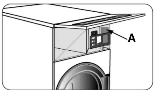
- A wiring diagram for your machine is located behind the front panel as shown (A).
SAFETY AND WARNING SIGNS
Replace If Missing Or Illegible
One or more of these signs must be affixed on each machine.
LOCATED AT THE REAR OF THE MACHINE:
INSTALLATION AND MAINTENANCE WARNINGS
- This machine should be installed on an uncovered concrete floor, in accordance with the installation instructions, to reduce the risk of fire and to prevent serious injury and damage to the machine.
- If installed on a floor of combustible material the floor area below this machine must be covered by a metal sheet extending to the outer edges of the machine.
- This machine MUST be connected to a dedicated electrical circuit to which no other lighting unit or general purpose receptacle is connected. Use copper conductors only.
- This machine MUST be serviced and operated in compliance with manufacturer's instructions. CHECK DOOR EVERY DAY FOR PROPER OPERATION TO PREVENT INJURY OR DAMAGE. IF THE DOOR INTERLOCK FAILS TO OPERATE PROPERLY, PLACE THE MACHINE OUT OF ORDER UNTIL THE PROBLEM IS CORRECTED.
- Disconnect power prior to any servicing of machine.
- To open the service panel for service on those models on which it is secured by screws and keylock at the front panel, use the key originally shipped in the drum package. Be certain to relock after the servicing.
MANUFACTURED BY NYBORG LAUNDRY MACHINES, TOMMERUP, DENMARK.
DISTRIBUTED BY WASCOMAT, INWOOD, NEW YORK, USA
AND BY WASCOMAT OF CANADA, MISSISSAUGA, ONTARIO, CANADA.
SOLD AND SERVICED BY INDEPENDENT WASCOMAT DEALERS.
MACHINE SHOULD NOT BE USED BY CHILDREN
487 18 97 31 2
If you need to order more safety or warning signs, call Wascomat's parts department at 516-371-2000 or call your local dealer.
487 18 97 32.
To order replacement parts, call Wascomat's parts department at 516.371.2000, or call your local dealer.
IMPORTANT

BEFORE CONNECTING POWER OR HEATING SUPPLIES,
REFER TO MACHINE DATA LABEL
BEHIND FRONT CONTROL PANEL.
For use only in
non-combustible locations
487 18 97 66.
SAFETY AND WARNINGS SIGNS
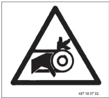
Dryer MUST NOT be operated with guards, outer panels, our service door/panels removed or not secured in place.
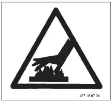
"Warning" High temperatures which could cause severe burns.
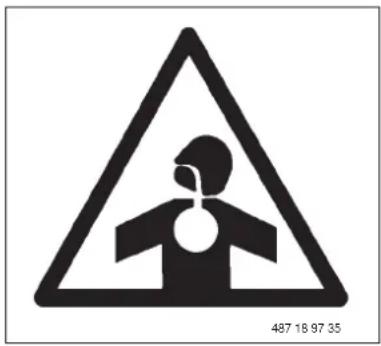
Must be exhausted to the outdoors

DO NOT OPERATE THIS APPLIANCE BEFORE READING THE INSTRUCTION BOOKLET.
DO NOT PLACE ARTICLES ON OR AGAINST THIS APPLIANCE.
DO NOT STORE CHEMICALS OR FLAMMABLE MATERIALS, OR SPRAY AEROSOLS NEAR THIS APPLIANCE.
DO NOT OPERATE WITH PANELS COVERS OR GUARDS REMOVED FROM THIS APPLIANCE.
DO NOT LOAD MATERIALS CONTAINING FLAMMABLE SOLVENTS INTO THIS APPLIANCE.
487 18 97 36.
IMPORTANT
DO NOT JUMP WIRES AROUND AIR SWITCH.
DO NOT TAPE SWITCH DAMPER SHUT.
DO NOT RESTRICT FLOW OF AIR TO SWITCH.
487 18 97 43.

WARNING
VALVE CONVERTED FOR USE ON LP GAS. REGULATOR BLOCKED OPEN! EXTERNAL REGULATOR REQUIRED! IMPROPER OPERATION COULD RESULT IN DEATH OR SERIOUS INJURY!

MISE EN GARDE
SOUPAPE CONVERTIE POUR USAGE SUR GAZ DE PETROLE LIQUEFIE. REGULATEUR BLOQUE EN POSITION OUVERTE! REGULATER EXTERNE NECESSAIRE! UN FONCTIONNEMENT INAPPROPRIE PEUT PROVOQUERLA MORT OU DES BLESSURES GRAVES.
487 18 97 40.0
LPG conversion kits.

WARNING
DO NOT store or use flammable liquids near the dryer.
DO NOT put articles soiled with flammable liquids in dryer.
DO NOT put articles soiled with vegetable or cooking oils in dryer.
DO NOT put articles containing foam rubber, plastic or similarly textured rubberlike materials in dryer.
DO NOT store or use aerosols or cleaning solvents in the vicinity of the dryer. Some chemicals used in laundries contain Chlorine (some dry-cleaning fluids, aerosols and bleach). When exposed to a flame, these chemicals may produce toxic fumes that are harmful to humans and highly corrosive.
DO NOT reach into dryer until all moving parts have stopped.
DO NOT let children play in or near dryer.
487 18 97 38.
CAUTION
THIS DRYER MUST BE EXHAUSTED TO THE OUTDOORS.
INSTRUCTIONS
INSPECT EXHAUST DUCTING EVERY 6 MONTHS AND REMOVE LINT BUILDUP.
487 18 97 42.

WARNING

PLUMBERS BEWARE WHEN PRESSURE TESTING!!!
DRYER MUST NOT BE SUBJECTED TO PRESSURE THAT EXCEEDS
1/2 psig (3.5kPa).
TO DO SO WILL CAUSE GAS LEAKS WHICH CAN RESULT IN FIRE OR EXPLOSION.
487 18 97 39.

WARNING

THIS DRYER AND ITS INDIVIDUAL SHUT-OFF VALVE MUST BE DISCONNECTED FROM THE GAS SUPPLY PIPING SYSTEM DURING ANY PRESSURE TESTING OF THAT SYSTEM AT TEST PRESSURES IN EXCESS OF 1/2 psig (3.5 kPa). THIS DRYER MUST BE ISOLATED FROM THE GAS SUPPLY PIPING SYSTEM BY CLOSING ITS INDIVIDUAL MANUAL SHUT-OFF VALVE DURING ANY PRESSURE TESTING OF THE GAS SUPPLY PIPING SYSTEM AT TEST PRESSURES EQUAL TO OR GREATER THAN 1/2 psig (3.5 kPa).
487 18 97 37.02
"Live voltage" Disconnect electrical power before servicing
LINT SCREEN MUST BE CLEANED IN ACCORDANCE WITH THE MANUFACTURER'S RECOMMENDED FREQUENCY GUIDELINES
487 18 97 41.
WARNING
THE DRYER MUST BE USED ONLY FOR DRYING WATER WASHED FABRICS.
HEAT MUST NOT BE USED FOR DRYING FOAM RUBBER ITEMS OR SIMILARLY TEXTURED RUBBERLIKE MATERIALS.
DO NOT DRY MOPHEADS OR ARTICLES EXPOSED TO GASOLINE, KEROSENE, PAINT, WAX, GREASE.
COMBUSTIBLE DETERGENT OR ALL PURPOSE CLEANERS.
REMOVE ARTICLES BEING DRIED IMMEDIATELY AFTER TUMBLER STOPS.
THIS DRYER IS NOT TO BE USED IN THE PRESENCE OF DRY CLEANING SOLVENTS.
487 18 97 44.
FOR YOUR SAFETY
DO NOT STORE OR USE GASOLINE OR OTHER FLAMMABLE VAPORS AND LIQUIDS IN THE VICINITY OF THIS OR ANY OTHER APPLIANCE,
DO NOT DRY MOP HEADS IN THE DRYER.
DO NOT USE DRYER IN THE PRESENCE OF DRY CLEANING FUMES.
IMPORTANT
YOU MUST DISCONNECT and LOCKOUT THE ELECTRIC SUPPLY and THE GAS SUPPLY or THE STEAM SUPPLY BEFORE ANY COVERS or GUARDS ARE REMOVED FROM THE MACHINE TO ALLOW ACCESS FOR CLEANING, ADJUSTING, INSTALLATION, or TESTING OF ANY EQUIPMENT per OSHA (Occupational Safety and Health Administration) STANDARDS.

WARNING
CHILDREN SHOULD NOT BE ALLOWED TO PLAY ON OR IN THE DRYER(S).CHILDREN SHOULD BE SUPERVISED IF NEAR DRYER(S) IN OPERATION.
CAUTION
Please observe all safety precautions displayed on the equipment and/or specified in the installation/operators manual included with the dryer.
Dryer(s) must not be installed or stored in an area where it will be exposed to water and / or weather,
The wiring diagram for the dryer is located in the front electrical control box area.
Electrical Information
It is your responsibility to have ALL electrical connections (including grounding) made by a properly licensed and competent electrician to assure that the electrical installation is adequate and conforms with local and state regulations or codes.
In the absence of such codes, ALL electrical connections, material, and workmanship must conform to the applicable requirements of the NATIONAL ELECTRIC CODE ANSI/NFPA NO. 70 or the CANADIAN ELECTRICAL CODE, CSA C22.1 - both the latest edition.
IMPORTANT: Failure to comply with these codes or ordinances and/or the requirements stipulated in this manual can result in personal injury or component failure.
NOTE: Component failure due to improper installation will VOID THE WARRANTY.
IMPORTANT: A separate circuit serving each dryer must be provided. The dryer must be connected to copper wire only. DO NOT use aluminum wire which could cause a fire hazard.
NOTE: The use of aluminum wire will VOID THE WARRANTY
CAUTION: Label all wires prior to disconnection when servicing controls. Wiring errors can cause improper operation or component failure.
Electric Service Gas dryers ONLY
IMPORTANT: The dryer must be connected to the electrical supply shown on the data label affixed to the dryer. In the case of 208 VAC or 240 VAC, the supply voltage must match the electric service specifications of the data label exactly. Wire must be properly sized to handle the rated current.

WARNING: 120 VAC, 208 VAC and 240 VAC ARE NOT THE SAME. Any damage done to dryer components due to improper voltage connections will VOID THE WARRANTY.
NOTE: On gas dryers, to convert from 120 VAC to 208 VAC or to 240 VAC (or vice versa), the Direct Spark Ignition (DSI) transformer wiring must be changed.
Gas Information
It is your responsibility to have ALL plumbing connections made by a qualified professional to insure that the installation is adequate and conforms with local and state regulations or codes. In the absence of such codes, ALL plumbing connections, material, and workmanship must conform to the applicable requirements of
the National Fuel Gas Code ANSI Z223.1 or the CAN/CGA-B149, INSTALLATION CODES - both the latest edition.
IMPORTANT: Failure to comply with these codes or ordinances, and/or the requirements stipulated in this manual, can result in personal injury and improper operation of the dryer.
The dryer and its individual shut-off valve must be disconnected from the gas supply piping system during any pressure testing of that system at test pressures in excess of 1/2 psig (3.5 kPa). The dryer must be isolated from the gas supply piping system by closing its individual manual shut-off valve during any pressure testing of the gas supply piping system at test pressures equal to or greater than 12 psig (3.5 kPa).
IMPORTANT: Failure to isolate or disconnect the dryer from the gas supply as noted can cause irreparable damage to the gas valve and will VOID THE WARRANTY.
WARNING: FIRES or EXPLOSION COULD RESULT.

Gas Supply
The gas dryer installation must meet the American National Standard, National Fuel Gas Code Z223.1-LATEST EDITION, as well as local codes and ordinances and must be done by a qualified professional,
NOTE: Undersized gas piping will result in ignition problems,
slow drying, increased use of energy, and can create a safety hazard.
The dryer must be connected to the type of heat/ gas indicated on the dryer data label. If this information does not agree with the type of gas available, do not operate the dryer. Contact your local dealer or the Wascomat Sales Department.
IMPORTANT: Any burner changes or conversions must be
made by a qualified licensed professional.
The input ratings shown on the dryer data label are for elevations of up to 2,000 feet. The adjustment or conversion of the dryer(s) in the field for elevations over 2,000 feet are made by changing each burner orifice.
Also for conversion to LPG there are conversion kits.
If these conversions are necessary, contact your local dealer or the Wascomat Sales Department.
Technical Gas Data
Natural Gas
The natural gas supply pressure to the dryer must be between 6 and 10 inches water column. If the pressure is too low, ignition failure and/or slow drying times may result. Excessively high supply pressure will result in erratic operation of the gas valve's internal pressure regulator. The pressure measured at the pressure tap on the body of the gas valve must be for TYPE 30: 4.2-inches water column, TYPE 50: 3.2 -inches water column and TYPE 75: 3.2 -inches water column
Liquid Petroleum (L.P.) Gas
Dryers made for use with L.P. gas have the gas valve pressure regulator blocked open, so that the gas pressure must be regulated upstream of the dryer. The pressure measured at the gas valve body pressure tap must be 11 inches water column. In accordance with American Gas Association (AGA) standards, a gas pressure regulator, when installed indoors, must be equipped with a vent limiter or a vent line must be installed from the gas pressure regulator vent to the outype oors. The water column pressure must be regulated at the source (L.P. tank), or an external regulator must be added to each dryer.
Piping/Connections
The dryer is provided with a 12 " N.P.T. (the model TYPE 75 has a 34 ") inlet pipe connection extending out the rear area or through the top of the dryer. For ease of servicing, the gas supply line of each dryer should have its own shut-off valve.
The size of the gas supply line (header) will vary depending on the distance this supply line travels from the gas meter or, in the case of L.P. gas, the supply tank, the number of tees, other gas-operated appliances, etc. Specific information regarding supply line size should be determined by the gas supplier.
NOTE: Undersized gas supply piping can create a low or inconsistent gas pressure which will result in erratic operation of the burner ignition system.
Consistent gas pressure is essential at ALL gas connections. It is recommended that a 34 -inch pipe gas loop be installed in the supply line serving the bank of dryers. An in-line pressure regulator must be installed in the gas supply line (header) if (natural) gas line pressure exceeds 12-inch-es water column pressure.
IMPORTANT: Water column pressure of TYPE: 30 4.2 -inches water column, TYPE: 50 3.2 -inches water column and TYPE: 75 3.2 -inches water column for natural gas dryers and 11.0 inches for L.P, dryers is required at the gas valve pressure tap of each dryer for proper and safe operation.
A 1/8" N.P.T. plugged tap, accessible for test gauge connection, must be installed in the main gas supply line immediately upstream of each dryer.
IMPORTANT: Pipe joint compounds that resist the action of natural gas and L.P. gas MUST BE used.
WARNING: Test ALL connections for leaks by brushing on a soapy water solution (liquid detergent also works well). NEVER TEST FOR GAS LEAKS WITH AN OPEN FLAME.
ALL components / materials must conform to NATIONAL FUEL GAS CODE specifications. It is important that gas pressure regulators meet applicable pressure requirements and that gas meters are rated for the total amount of appliance Btu's being supplied.
Contents:
Instructions for use:....17
Diagram of tumble dryer
Manual operation
Aqua Clean wash and drying programs
Error codes
Running hours counter
Maintenance
General installation: 25
Setup: unpacking, positioning, mechanical installation
Reversing door
Venting
Installation gas heating: 31
Machine dimension
Technical data
Electricl installation, function check
Fuse sizes, effects and voltages
Gas installation
Parameter programming: 45
Switching to programming mode
Adjustable parameters, change machine type
Temperature and time setting, reversing
Cooling time, residual moisture level, extra drying time
Quick view parameter list.

Safety instructions

This machine is only intended for drying water-washed garments.
The machine must not be used for drying foam rubber or foam-like materials.
The machine must not be used for drying *floor mops.
The machine must not be used by children.
The machine must not be hosed down with water.
Mechanical, electrical and gas installations must only be carried out by authorized personnel.
If the machine has a fault, this must be reported as soon as possible to the person in charge. This is important for your own safety and for the safety of others.
Machine with gas heating is not to be installed in rooms containing cleaning machines with perchloroethylene, TRICHLOROETHYLENE or CHLOROFLUOROCONTAINING HYDROCARBONS as cleaning agents.
*Applies only to mop heads containing polypropylene.
The manufacturer reserves the right to modify design and material specifications without notice.
Diagram of tumble dryer
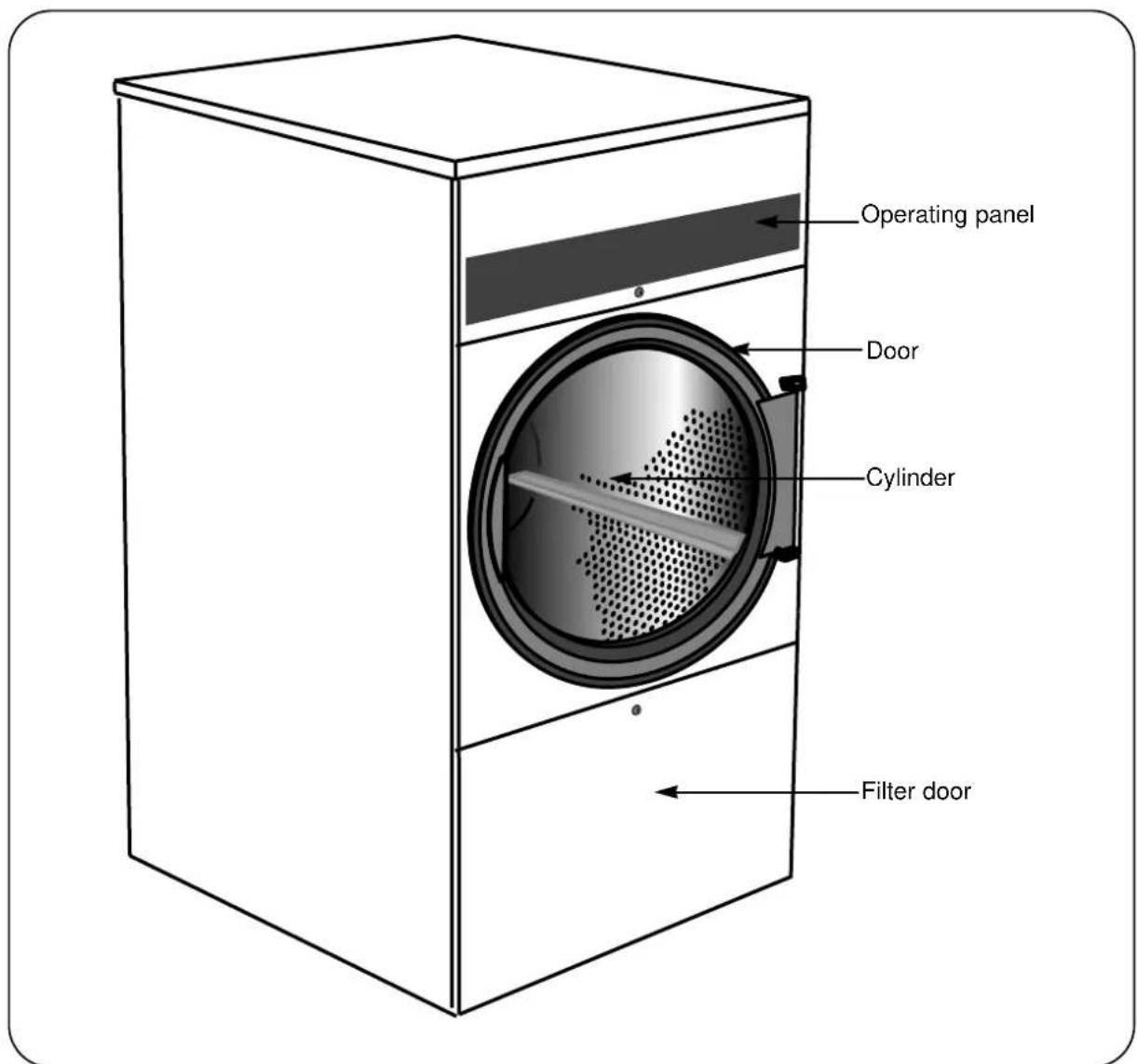
Manual operation with RMC (residual moisture control)
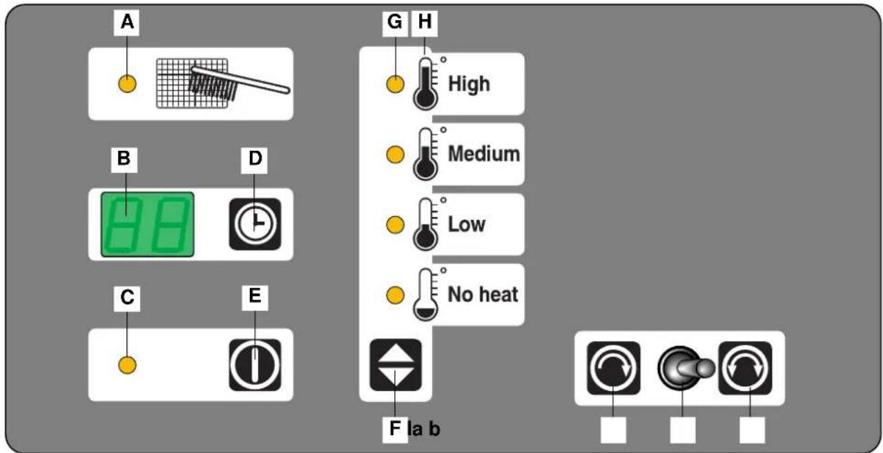
A. Filter: When the lamp is lit, the lint filter must be cleaned.
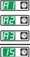
B. Display indicates program: A1, A2, A3 – or in time control version: drying time/time remaining
C. Operating lamp indicates when machine is in use.
D. Program selection button/drying-time adjuster.
E. Start/stop button.
F. Temperature selection button.
G. Lamps: lit to indicate selected temperature.
H. Temperature.
I. Reversing switch: a = Reversing off
b = Reversing on

Manual operation with RMC (residual moisture control)
 |  | Load garments into the machine and close the door | 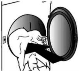 | |
 | Select the program: A1, A2, A3 or timer | 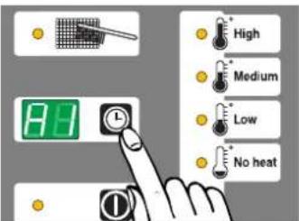 | 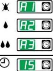 | Dryness 1 (see programming instructions)Dryness 2 (see programming instructions)Dryness 3 (see programming instructions)Time control in minutes |
 | Select temperature | 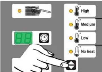 | Use for durable items, outer garments and wool | |
| Use for synthetic and delicate textiles (eg. silk, acetate, angora and rayon) | ||||
| No-heat setting | ||||
 |  | The machine will stop automatically when the moisture level reaches the value set for the selected program. The machine stops when the selected time has ended. | Reversing switch: Select option, with or without reversing.OFF 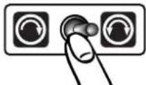 ON ON | |
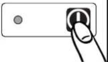
 | Start: Press the start/stop button | Stop: Press the start/stop button or open the door.Caution! Garments may fall out when the door is opened. | Restart: Close the door again and press the start/stop button. | The last few minutes of the drying time are the cooling-down period (the garments are cooled). |
 | ||||
 | To prevent wrinkling: empty the tumble dryer as soon as the program has ended. | 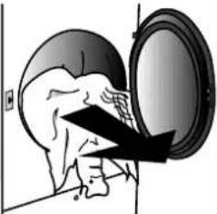 | If the tumble dryer is not emptied after the drying time has ended, an anti-wrinkle program is automatically started. This means that the cylinder rotates at short intervals, thereby almost completely avoiding wrinkling. | |
Aqua Clean wash and drying programs
Aqua Clean Washers: 125 EX30c, 225 EX50c, 400 EX90 FC
Aqua Clean Dryers: TD30 RMC, TD50 RMC, TD75 RMC
| Type of garments | Aqua Clean Program | Drying-program | RMC % | Time | Temp. setting |
| Outer garments without sensitive linings | Ewac 11-21-31 | A2 10-12 % High | |||
| Outer garments with sensitive linings | Ewac 13-23-33 | A3 15-18 % High | |||
| Active textiles Sympatex, Goretex, down | Ewac 12-22-32 | A1 0-2 % Medium | |||
| Delicate garments Synthetic | Ewac 13-23-33 | A2 10-12 % High | |||
| Delicate garments Wool | Ewac 14-24-34 | A2 10-12 % High | |||
| Delicate garments Silk | Ewac 15-25-35 | A2 10-12 % High | |||
| Delicate garments Acetate, Angora, Cashmere | Ewac 15-25-35 | A3 15-18 % High | |||
| Leather & suede (Hang dry after wash) Ewac 16-26-36 20-40 min. Medium | |||||
Program Ewac 11-16 for full load (filling factor 1:20)
Program Ewac 21-26 for half load
Program Ewac 31-36 for single garment load
Error codes
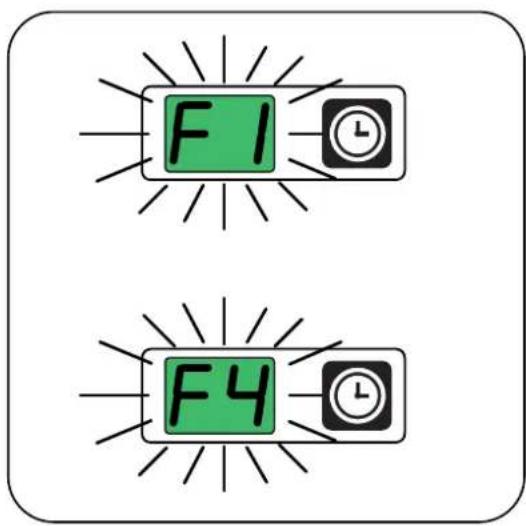
These machines feature automatic fault reporting, displayed in the form of flashing error codes.
F1 = Machine type has not been set.
"F1" is shown after the control circuit board has been changed or if power is connected to the machine while the service program is active. (Machine type should be set in the service program).
F4 = The thermal sensor is disconnected.
Check for loose or broken connections.
Running hours counter
The machine is equipped with a running hour counter to track the number of hours that the machine has been in operation.
The running hours read-out (a 6-digit number) is given in the display.
The total running hour counter valve is shown each time the power is connected to the machine.
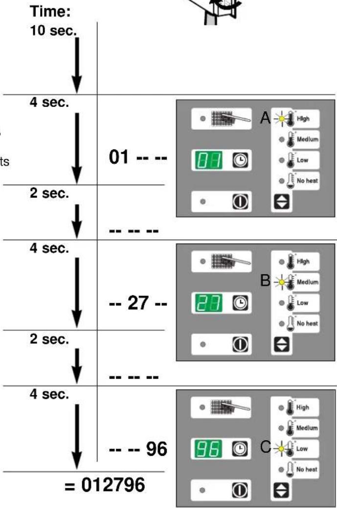
Example of machine having run for 12796 hours:
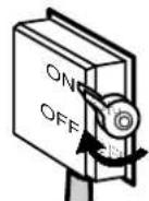
Switch the machine off and on again.
After approx. 10 seconds
the first two digits of a 6-digit number 01 — — are shown, and at the same time, lamp A lights up. After 4 seconds, the lamp and the two digits are turned off.
After a two-second pause
the next two digits - 27 - show while lamp B is lit. After 4 seconds, the lamp and the two digits are turned off.
After a two-second pause
the last two digits, — — 96 are shown, with lamp C lit, for 4 seconds.
Altogether, the machine has been in operation for 01-27-96 = 12796 hours.
The machine will complete its power-on testing sequence and be ready for use after a short time
flowchart
graph TD
    A["Time: 10 sec."] --> B["4 sec."]
    B --> C["2 sec."]
    C --> D["4 sec."]
    D --> E["2 sec."]
    E --> F["4 sec."]
    F --> G["= 012796"]

    H["Control Panel A"] --> I["High"]
    H --> J["Medium"]
    H --> K["Low"]
    H --> L["No heat"]

    M["Control Panel B"] --> N["High"]
    M --> O["Medium"]
    M --> P["Low"]
    M --> Q["No heat"]

    R["Control Panel C"] --> S["High"]
    R --> T["Medium"]
    R --> U["Low"]
    R --> V["No heat"]
Maintenance
The following should be carried out at regular intervals, depending on machine usage.
Daily
- Check that the machine does not operate when the door is open.
- Check that the machine does not start until the door is closed and the start button has been pressed.
- Clean the door gasket (use a moist cloth).
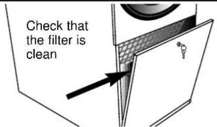
- Cleaning of lint filter compartment:
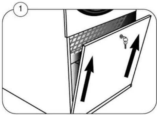
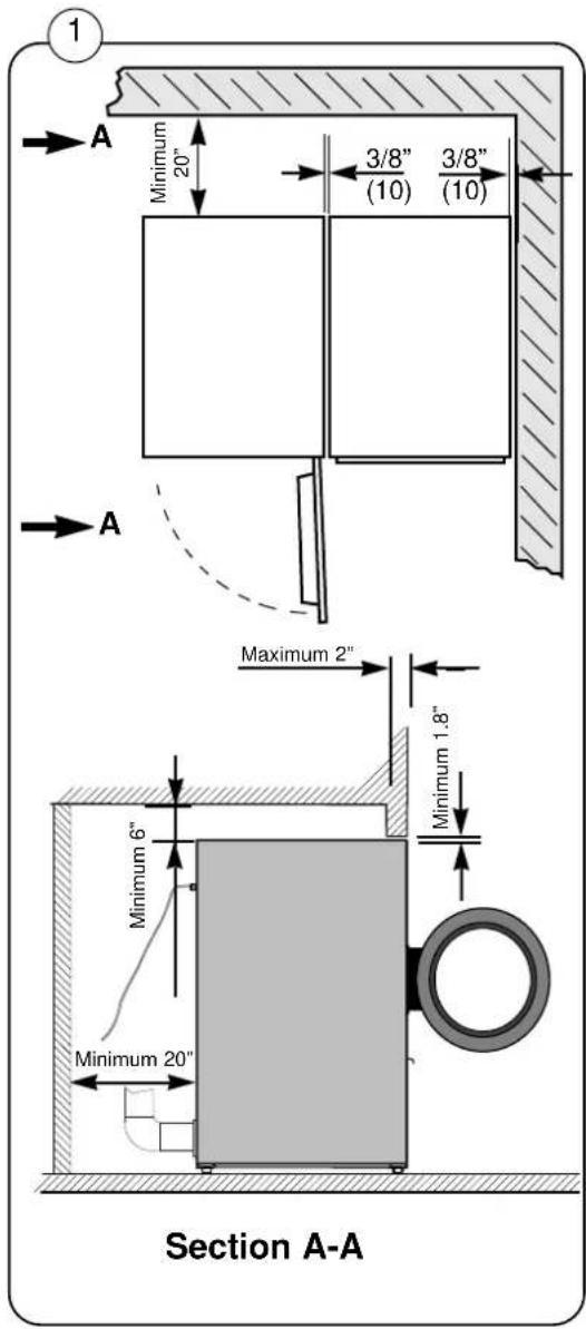
① Remove the lint compartment door by opening it and pulling it upwards. It is not necessary to remove the lint filter for cleaning. The air system of the machine ensures that lint and dust settle automatically at the bottom of the filter compartment, so that they can be removed with a broom or vacuum-cleaner.
- Check that the lint filter is not damaged.
Quarterly/Semi-annually
- Check that the fresh-air intake at the back of the machine is not clogged by lint or otherwise blocked.
- Check that the exhaust system connections are tight and that the ducts are not clogged by lint or dust or otherwise blocked.
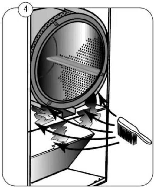
- Remove the lint filter and check that the fan wheel is not clogged by lint or otherwise blocked.
• Gently clean the lint filter with warm water and a soft brush. Allow the filter to dry then re-install it.
natural_image
Diagram showing a door with arrows indicating movement or force, no text or symbols present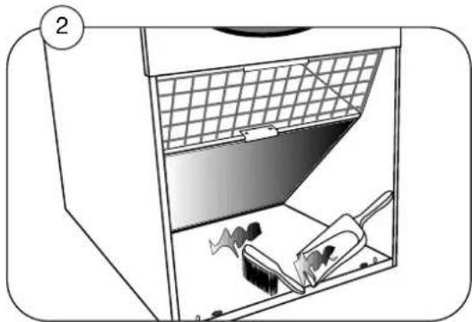
natural_image
Diagram of a kitchen appliance with a grater inside, showing internal components and a handle (no text or symbols)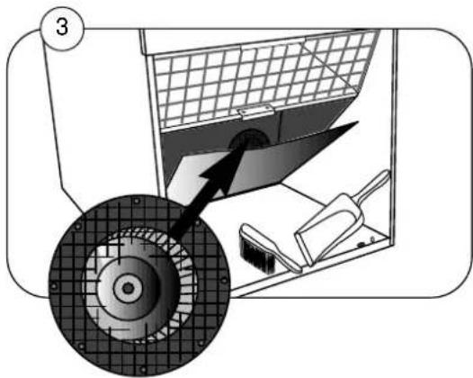
natural_image
Diagram of a mechanical device with a rotating wheel and internal components, no visible text or symbolsMaintenance continued
Annually
4 Check that the fresh-air intake to the room and exhaust ducts from the room are not clogged by lint or dust or otherwise blocked.
Clean, as required, depending on machine usage - once a year as a minimum.
- Remove the front panel and finger protector. Clean all accumulated lint and dust.
- At least once a year a qualified service technician should check the internal parts of the machine and thoroughly clean them of lint and dirt.
Lubrication
The motor bearings, idler bearings, and tumbler bearings are permanently lubricated.
No lubrication is necessary.
natural_image
Diagram of a mechanical device with internal components and airflow arrows, no text or symbols presentSetup, type 30 and 50
Unpacking
When unpacking the machine, handle it with care. There are no transport brackets to remove.
The tumble dryer is fastened to the pallet by three screws. Remove the two front screws by opening the filter lid. Remove the back screw by unscrewing and removing the bottom back-plate.
Positioning
Position the tumble dryer so that there is plenty of room for working, both for the user and for the service technician.
The distance from the wall or other equipment behind the tumble dryer should be at least 20" (500 mm) and the space at the sides at least 3/8" (10 mm).
Note that, for servicing purposes, access to the rear of the tumble dryer is required.
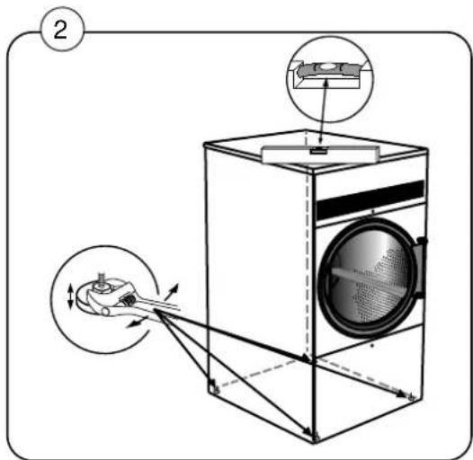
Mechanical installation
Adjust the machine to make it stand horizontally and stably on all four feet.
The max. height adjustment of the feet is 5/8" (15 mm)
Setup, type 75
Unpacking
When unpacking the machine, handle it with care. There are no transport brackets to remove.
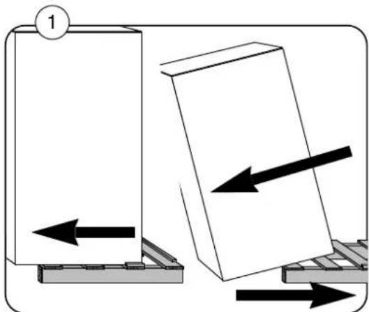
The tumble dryer is fastened to the pallet by four screws. Remove the two front screws by opening the lint filter panel. Remove the two back screws by unscrewing and removing the bottom back-plate.
① Carefully push the tumble dryer back so that it can be tipped backwards to allow the pallet to be pulled out from beneath it.
② Put the tumble dryer into position, tipping it up to install the four supplied feet.
Positioning
Position the tumble dryer so that there is plenty of room for working, both for the user and for the service technician.
③ The distance from the wall or other equipment behind the tumble dryer should be at least 20" (500 mm) and the space at the sides at least 3/8" (10 mm).
Note that, for servicing purposes, access to the rear of the tumble dryer is required.
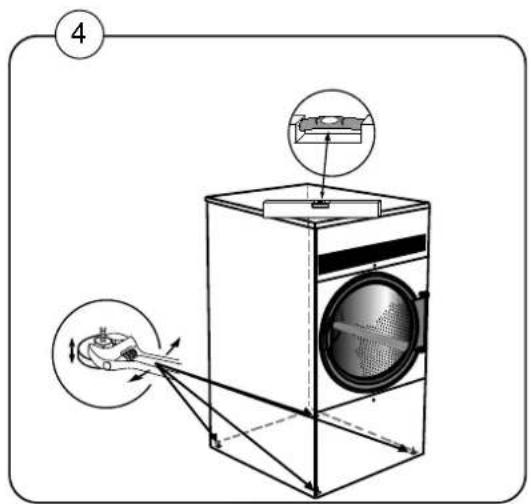
Mechanical installation
④ Adjust the machine to make it stand horizontally and stably on all four feet.
The max. height adjustment of the feet is 5/8" (15 mm).
natural_image
Diagram showing two mechanical components with directional arrows indicating movement, no text or symbols present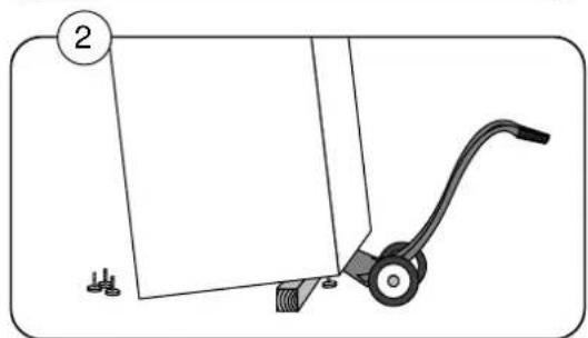
natural_image
Diagram of a mechanical lever system with a numbered label (2) and no visible text or symbols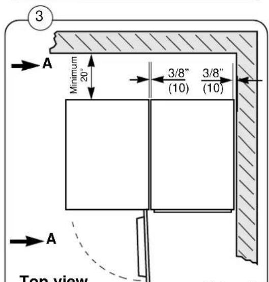
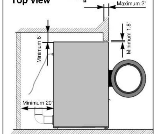
Section A-A
Reversing the door
The tumble dryer is usually delivered with a right hinged door but the door can easily be changed to left hinged position.
Dryer door reversal instructions
① Disconnect the power supply to the machine.
Remove the screws that secure the center-front panel to the machine and remove the entire panel (with the door mounted on it).
Move the door switch to the opposite side of the machine.
Turn the front panel over and re-mount it.
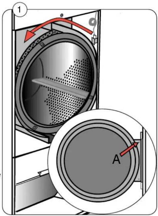
Unscrew the door-switch pin from the inside of the hinge flange and move it to the opposite edge of the flange A. The new pin location must correspond with the new position of the door switch.
Restore power to the machine and check for proper operation of the door switch, as follows:
- With the door open, attempt to start the dryer. It must not start.
- Close the door and start the machine. Open the door. The dryer must stop.
If the dryer starts with the door open, or fails to stop when the door is opened during operation, repair or replace the door switch, as necessary.
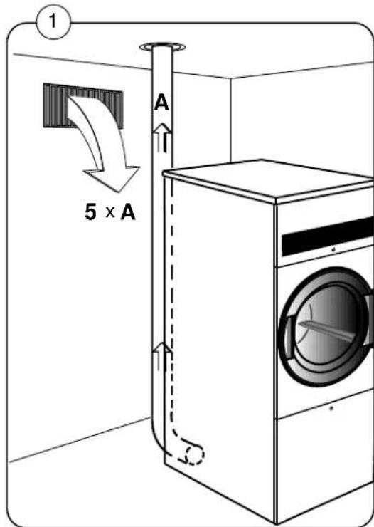
Tumble dryer inlet air requirements
Fresh- air

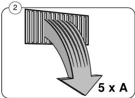
For maximum efficiency and the shortest possible drying time, it is important to ensure that fresh air is able to enter the room from the outside in the same volume as that blown out of the room. To avoid a draught in the room, it is advisable to place the air inlet behind the machine. *The area of the air inlet opening must be 5 times the size of the vent pipe area.
The resistance in the grating/slats on the air-inlet cover plate should not exceed 10 Pa (0.1 mbar).
Type 30: The air consumption is approx. 410 CFM (690 m³/h).
Type 50: The air consumption is approx. 680 CFM (1160 m³/h).
Type 75: The air consumption is approx. 650 CFM (1100 m³/h).

*The area of the inlet opening is the area through which the air can flow without resistance from grating/slatted cover.
Note that gratings/slatted covers often block half of the total fresh air vent area. Remember to take this into account.
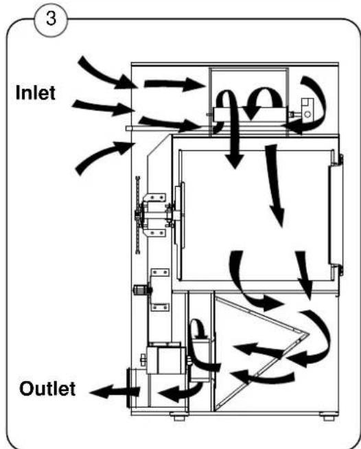
Air principle
The blower creates low pressure in the cylinder, drawing air into the machine via the heating unit.
The heated air passes through the garments and the cylinder vents.
Then the air flows out through a lint filter, positioned immediately in front of the blower. After this, the air is evacuated through the ventilator and exhaust ducts.
flowchart
graph TD
    A["Inlet"] --> B["Flow Path 1"]
    B --> C["Flow Path 2"]
    C --> D["Outlet"]
    style A fill:#f9f,stroke:#333
    style D fill:#bbf,stroke:#333
487 18 94 81 - 30/50/75 - Aqua Clean Wascomat
Tumble dryer exhaust system
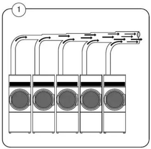
Exhaust system for installation of several machines with a shared exhaust duct
When installing several machines on a shared exhaust duct, increase the area of the duct with each additional machine, so that each machine will be working at the same air resistance. Fig. 1 and the table show in simplified form how the exhaust duct should look.
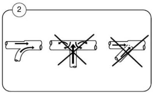
Note: To keep the air flowing, ensure proper machine operation, and minimize lint buildup in the exhaust system, never connect ducts at right angles, always use gentle bends. See fig. 2.
flowchart
graph TD
    A["1"] --> B["Top Air Outlet"]
    B --> C["Three Washers"]
    C --> D["Four Washers"]
    D --> E["Bottom Washers"]
    E --> F["Top Air Outlet"]
    style A fill:#f9f,stroke:#333
    style B fill:#ccf,stroke:#333
    style C fill:#cfc,stroke:#333
    style D fill:#fcc,stroke:#333
    style E fill:#cff,stroke:#333
    style F fill:#ffc,stroke:#333
| Number of tumble dryers | 1 2 3 4 5 6 7 8 9 10 |
| Exhaust pipe diameter, inches | 7^3/4" 11" 12 ^3/8" 14" 15 ^3/4" 17 ^3/4" 18 ^3/4" 19 ^5/8" 21" 22"(200) (280) (315) (355) (400) (450) (475) (500) (535) (560) |
| Required area of fresh-air inlet,Square feet ( m^2 )(minimum) | 1^5/8 3 ^1/4 4 ^7/8 6 ^1/2 8 ^1/16 9 ^5/8 11 ^5/16 13 ^14 ^1/2 ^16 ^1/8 (1.05) (0.35) (0.45) (0.60) (0.75) (0.90) (1.05) (1.20) (1.35) (1.50) |
Each machine requires a 5^3/4 " x 5^3/4 " fresh-air inlet opening. (400 x 400 mm)
Tumble dryer exhaust system
Exhaust duct
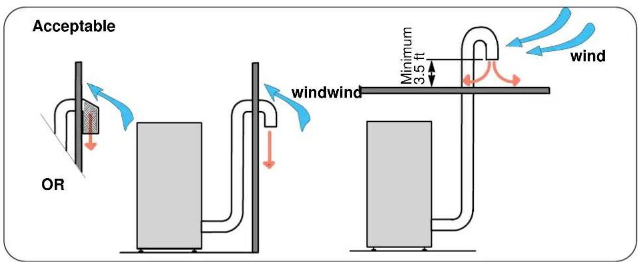
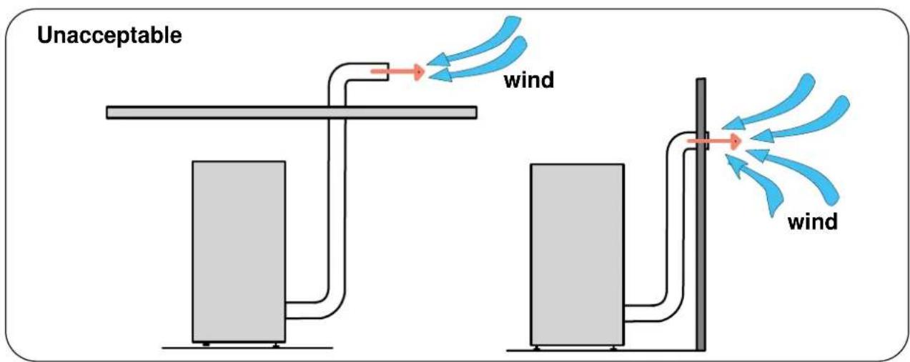
It is recommended to connect each machine to a separate, smooth exhaust duct with the lowest possible air resistance. The duct must lead into the open, where lint and steam will not be a hazard. The outlet must be protected against rain and foreign objects
The exhaust duct must be designed to minimize backpressure. The end of the exhaust duct must never be exposed to wind pressure.
Note: In cold areas, condensation may cause frost damage to the building.
If you have questions relating to the design of the exhaust system, please contact your local dealer or Wascomat's Customer Service Department.
Maximum duct length
| With With With1 elbow 2 elbow 3 elbow | ||
| TD 30 30 ft 24 ft 18 ft | ||
| TD 50 30 ft 24 ft 18 ft | ||
| TD 75 100 ft 94 ft 88 ft | ||
Exhaust illustrations
Mashine Dimensions
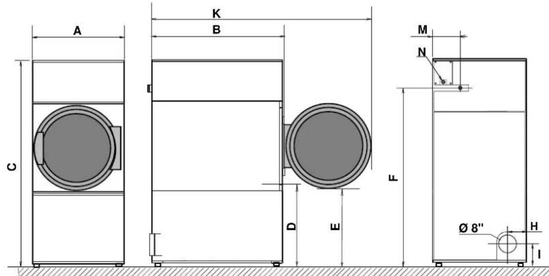
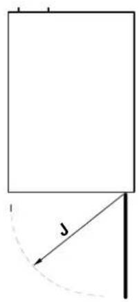
| A B | C D E F | G H | ||||||
| Type 30 | 28"(710) | 44"(1120) | 74"(1880) | 30 3/4"(780) | 28 1/2"(725) | 63 1/3"(1610) | -- | 5 1/4"(135) |
| Type 50 | 37^3/4 (960) | 46 ^1/2 " (1180) | 78 ^1/2 " (1995) | 28 ^1/3 " (720) | 25 ^1/2 " (650) | 68" - 6"(1725) | - | (155) |
| Type 75 | 37^3/4 " (960) | 54"(1370) | 78 ^1/2 " (1995) | 28 ^1/3 " (720) | 25 ^1/2 " (650) | 68" - 6"(1725) | - | (155) |
| I | J K L M | N | ||||||
| Type 30 | 6^3/4 " (170) | 28"(710) | 71 ^1/4 " (1810) | -- | 9" -(250) | |||
| Type 50 8 | ^3/4 " (225) | 37 ^3/4 " (960) | 83 ^1/2 " (2120) | -- | 10 ^1/2 " (270) | - | ||
| Type 75 8 | ^3/4 " (225) | 37 ^3/4 " (960) | 90 ^1/2 " (2300) | - 10- | ^1/2 " (270) | - | ||
| Type 30 Type 50 and 75 | |
| D Door opening dia. | 22 ^3/_4 "(580) 32"(810) |
| G/L Not in use on this model | |
| F/M Gas connection (gas models) | |
| N Electric connection (gas models) | |
All dimensions given in inches ±1/8" Inch (mm)
Technical data, type 30
| Heating Gas | |||
| Cylinder volume: (286 litres) 10.1 cu.ft. | |||
| Weight: Net (220 kg) 485 lbs | |||
| Cylinder: Diameter (680 mm) 26Depth (790 mm) 31"Revolutions per minute 44 rpmG-factor 0.8 | 3/4" | ||
| Capacity: 13.6 kg 30 lb | |||
| Motor single phase: Effect of cylinder/vent motor 0.5hp/ 0.37 kWRevolutions per minute 60 Hz 1680 rpm | |||
| Motor three phase: Effect of cylinder/vent motorEffect with reverse:CylinderBlowerRevolutions per minute 60 Hz 1680 rpm | 0.5hp/ 0.37 kW0.5hp/0.37kW0.5hp/0.37kW | ||
| Heat effect: Gas heating (21kW) | 71600 BTU/h | ||
| Air consumption: Gas (690 m3/h) | 410 cu.ft./min | ||
| Pipe connection: Evacuation: (∅200) | ∅ 8" | ||
| Drop in pressure: Evacuation: (20Pa) | max. 0.1" W.C | ||
| Gas pipe connection: (ISO 7/1-R1/2) | 1/2" NPT | ||
| Gas pressure: GNH (Natural gas) MinimumMaximumLPG (L.P.gas) MinimumMaximum | 3.5" W.C.10" W.C.8" W.C.13" W.C. | ||
| Noise level: | < 70 dB (A) | ||
Installation - gas heating
Technical data, type 50
Heating Gas
| Cylinder volume: (528 litres) 18.6 cu.ft. | |||
| Weight:Net (332 kg) | 732 lbs | ||
| Cylinder: Diameter (913 mm) 36"Depth (812 mm) 32"Revolutions per minute 40 rpmG-factor 0.8 | |||
| Capacity: 22.7 kg 50 lb | |||
| Motor single phase: Effect of cylinder/vent motor 1.5hp/ 1.1kWRevolutions per minute 60 Hz | 1720 rpm | ||
| Motor three phase: Effect of cylinderEffect of blowerRevolutions per minute 60 Hz | 0.5hp/0.37 kW0.5hp/0.37 kW1680 rpm | ||
| Heat effect: Gas heating (40 kW) | 136400 BTU/h | ||
| Air consumption: Gas (1160 m3/h) | 680 cu.ft./min | ||
| Pipe connection: | ∅ 8" | ||
| Drop in pressure: Evacuation (60Pa) | max. 0.23" W.C. | ||
| Gas pipe connection: (ISO 7/1-R1/2) | 1/2" N.P.T | ||
| Gas pressure: GNH (Natural gas): MinimumMaximumLPG (L.P.gas): MinimumMaximum | 3.5" W.C.10" W.C.8" W.C.13" W.C. | ||
| Noise level: | < 70 dB (A) | ||
| Technical data, type 75Heating Gas | ||
| Cylinder volume: (650 litres) 23 cu.ft. | ||
| Weight: Net (345 kg) 760 lbs | ||
| Cylinder: Diameter (913 mm) 36"Depth (998 mm) 39Revolutions per minute 44 rpmG-factor 0.9 | 1/4" | |
| Capacity: 34.1 kg 75 lb | ||
| Motor single phase: Effect of cylinder motor 1.5hp/1.1 kWEffect of blower motorCylinder: Revolutions per minute 60 HzVentilator: Revolutions per minute 60 Hz | 1.0hp/0.75 kW1720 rpm3400 rpm | |
| Motor three phase: Effect of cylinder motorEffect of blower motorCylinder: Revolutions per minute 60 HzVentilator: Revolutions per minute 60 Hz | 0.5hp/ 0.37kW1.0hp/0.75 kW1680 rpm3400 rpm | |
| Heat effect: Gas heating (44.3 kW) | 151200 BTU/h | |
| Air consumption Gas (1100 m3/h) | 650 cu.ft./min | |
| Pipe connection: Evacuation (∅200) | ∅ 8" | |
| Drop in pressure: Evacuation (340 Pa) | max. 1.3" W.C. | |
| Gas pipe connection: (ISO 7/1-R3/4) | 3/4" NPT | |
| Gas pressure: GNH (Natural gas) MinimumMaximumLPG (L.P.gas) MinimumMaximum | 3.5" W.C.10" W.C.8" W.C.13" W.C. | |
| Noise level: | < 70 dB (A) | |
Electrical installation: Gas heating

It is your responsibility to have ALL electrical connections (including grounding) made by a properly licensed and competent electrician to assure that the electric installation is adequate and conforms with local and state regulations or codes.

In the absence of such codes, ALL electric connections, material, and workmanship must conform to the applicable requirements of the NATIONAL ELECTRIC CODE ANSI/NFPA NO. 70-or the CANADIAN ELECTRICAL CODE, CSA C22.1 - both the latest edition.
A separate circuit serving each dryer must be provided. The dryer must be connected to copper wire only. DO NOT use aluminum wire which could cause a fire hazard.
Important
The machine is equipped with a control circuit transformer with 4 selections for incoming supply Voltages:
120, 200/208, 220/230, and 240V.
① Check the transformer taps. The connection of the primary voltage on the transformer taps must be exactly the same voltage as specified on the dryer's data label.
Connecting the power cable:
A wiring diagram is included with each dryer showing the wiring connection sequence. The electrical connections are made at the terminal block located at the rear top area of the dryer
② The dryer is shipped with three (3) connection points: Voltage 208-240, 120: L1, N and Ground fig. 2.
③ Or four (4) connection points: Voltage 208-240: L1, L2, L3 and Ground fig. 3.
Cable dimension:
Refer to local codes to determine proper size of power cable.
Circuit breaker raitings are given on the following pages.
Function check see next page
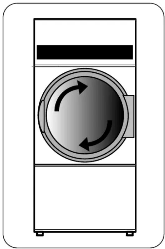
(NB: Correct direction of rotation is important!)
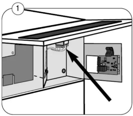
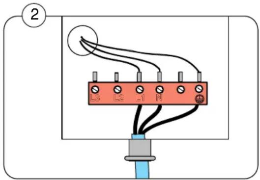
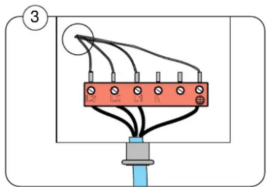
Electrical installation
Function check
This procedure must be carried out by qualified personnel.
Check that the cylinder is empty and the door is closed.
Start the machine.
Check that the safety lock is working: The cylinder, blower and heat must stop if the front door is opened approximately 2".
The initial direction of rotation should be clockwise (see illustration). If the direction is reversed, swap two powerline phases (on 3 phase machines).
Let the machine operate for 5 minutes on a program that requires heat. Then check whether the heating is working by opening the front door to check if heat can be felt inside the drum.
If the above checks are found to be in order, the dryer is ready for use.
If problems exist, please contact your local dealer or Wascomat's Customer Service Department.
natural_image
Diagram of a washing machine with circular inlet and two curved arrows indicating clockwise flow (no text or symbols)Electrical installation - Tumble dryer type 30
Note: Use common-trip, single-lever circuit breakers only
Gas heating, circuit breaker ratings, power consumption and voltages
| Only one cable for control and motor | Voltage | Total input | Circuit breaker |
| 208 - 240V 3AC 60 Hz 1.5 kW 15A | |||
| 208 - 240V 1AC 60 Hz 0.7 kW 15A | |||
| 120V 1AC 60 Hz 0.7 kW 15A | |||
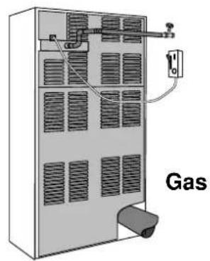
Electrical installation - Tumble dryer type 50
Note: Use common-trip, single-lever circuit breakers only
Gas heating, circuit breaker ratings, power consumption and voltages
| Only one cable for control and motor | Voltage Total | input | Circuit breaker |
| 208 - 240V 3AC 60 Hz 1.5 kW 15A | |||
| 208 - 240V 1AC 60 Hz 1.0 kW 15A | |||
| 120V 1AC 60 Hz 1.0 kW 15A | |||
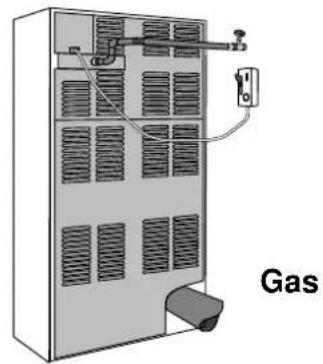
natural_image
Diagram of a gasifier unit with cooling fins and piping (no text or symbols)Electrical installation - Tumble dryer type 75
Note: Use common-trip, single-lever circuit breakers only
Gas heating, circuit breaker ratings, power consumption and voltages
| Only one cable for control and motor | Voltage Total | input | Circuit breaker |
| 208 - 240V 3AC 60 Hz 2.0 kW 15A | |||
| 208 - 240V 1AC 60 Hz 2.0 kW 15A | |||
| 120V 1AC 60 Hz 2.0 kW 20A | |||
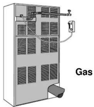
natural_image
Diagram of a gasifier unit with cooling fans and heat exchangers, labeled 'Gas' (no text or symbols on the diagram itself)Gas installation

It is your responsibility to have all plumbing connections made by a qualified professional to insure that the gas plumbing installation is adequate and conforms with local and state regulations or codes. In the absence of such codes, ALL plumbing connections, material, and workmanship must conform to the applicable requirements of the National Fuel Gas Code ANSI Z223.1-LATEST EDITION.
Fit the enclosed manual gas shutoff valve upstream from the dryer.
The gas connection to the machine should be sized for to an output of 71600, 136400 or 151200 Btu/h depending upon the size of the machine.
The machine is fitted with a general gas burner.
The factory nozzle pressure setting corresponds to the fuel value given on the nameplate.
Note: If converting to a different type of gas, an appropriate sign (supplied) must replace the existing plate on the machine.
Check that the nozzle pressure and fuel value agree with the values given in the table. If not, contact your gas supplier.
Bleed the pipe system before connecting the machine.
After connection, test all joints for leaks.
The dryer and its individual shutoff valve must be disconnected from the gas supply piping system during any pressure testing of that system at test pressures in excess of 1/2 psig (3.5 kPa).
The dryer must be isolated from the gas supply piping system by closing its individual manual shut-off valve during any pressure testing of the gas supply piping system at test pressures equal to or greater than 1/2 psig (3.5 kPa).
① A minimum 18 inch NPT plugged tap, accessible for test gage connection, must be installed immediately upstream of the gas supply connections to the dryer.
For gas valves, pressure and adjustment tables, see pages regarding gas valves.
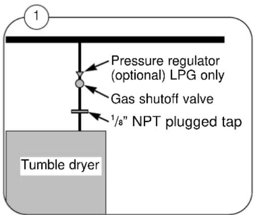
Gas installation
Test run
Turn gas control knob to OFF.
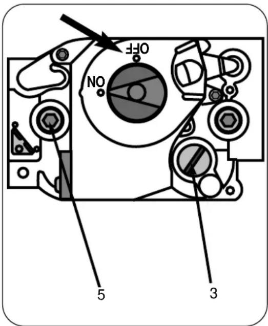
Remove outlet pressure tap plug from gas control and connect a manometer (pressure gauge) to the outlet pressure tap (5). (See pages regarding gas valves).
Turn gas control knob to ON position.
If necessary, adjust pressure regulator screw under cap screw (3), as follows:
- Remove pressure regulator adjustment cap screw.
- Turn adjustment screw clockwise to increase or counterclockwise to decrease gas pressure to main burner.
Select a program with heat and start the machine.
Check that the gas is burning evenly and with a bluish flame.
After testing replace cap screw and tighten firmly to prevent gas leakage. Close the service panel and place the machine in service.
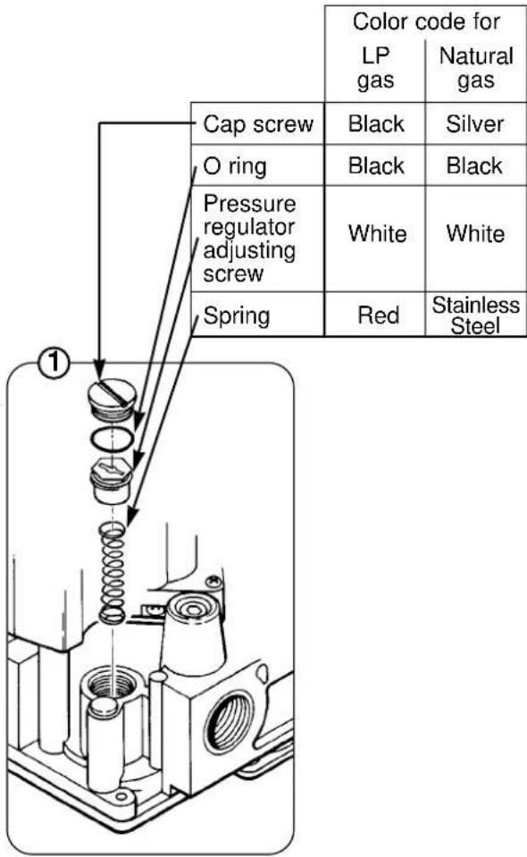
Gas installation
To convert from one gas to another:
- Turn off gas supply at the appliance service valve.
- Remove regulator cap screw and pressure regulator adjusting screw. Refer to Fig. 1.
- Remove the existing spring.
- Insert the replacement spring. Refer to Fig. 1.
-
Install the new plastic pressure regulator adjustment screw. Assure that the screw top is flush with the regulator top.
-
Turn pressure regulator adjustment screw clockwise eleven complete turns. The preliminary pressure setting is approximately
11.0 in. wc (2.7 kPa) for LP gas regulator 393691
and 3.5 in wc (0.9 kPa) for natural gas regulator 394588
- Check the regulator setting using a manometer.
- Install the new cap screw and O ring.
- Mount conversion label on the gas control.
Start-up
Gas control knob settings
OFF: Prevents main burner gas flow.
ON: Permits gas flow into gas control. Main burner gas flow is controlled by thermostat and automatic valve operators.
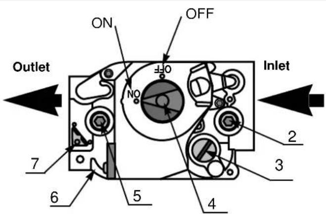
Gas valve
- Nozzle
- Inlet pressure tap
- Pressure regulator adjustment (Under cap screw)
- Gas control knob
- Outlet pressure tap
- Wiring terminals
- Ground terminals
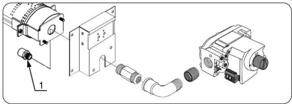
Gas installation - tumble dryer type 30, 50 and 75
Dryer type 30
Gas type: LPG
GNH
natural_image
Technical diagram of a mechanical assembly with labeled parts, showing exploded view and connection details (no text or symbols present)Dryer type 50
Gas type: LPG
GNH
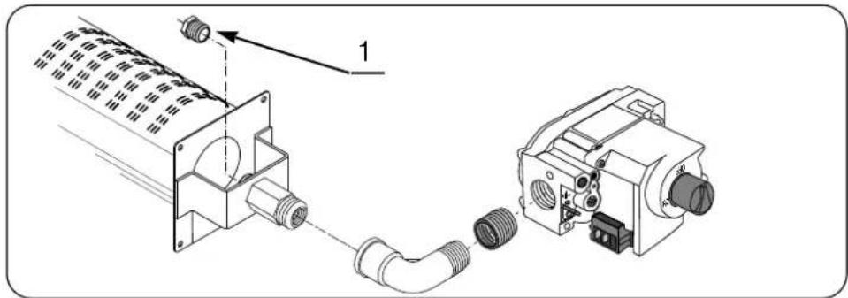
natural_image
Technical diagram showing a mechanical assembly with connectors and a motor (no text or symbols present)Dryer type 75
Gas type: LPG
GNH
Air reducingplate
A must be
mounted when
converting to
LPG and dis-
mounted when
converting to
GNH.
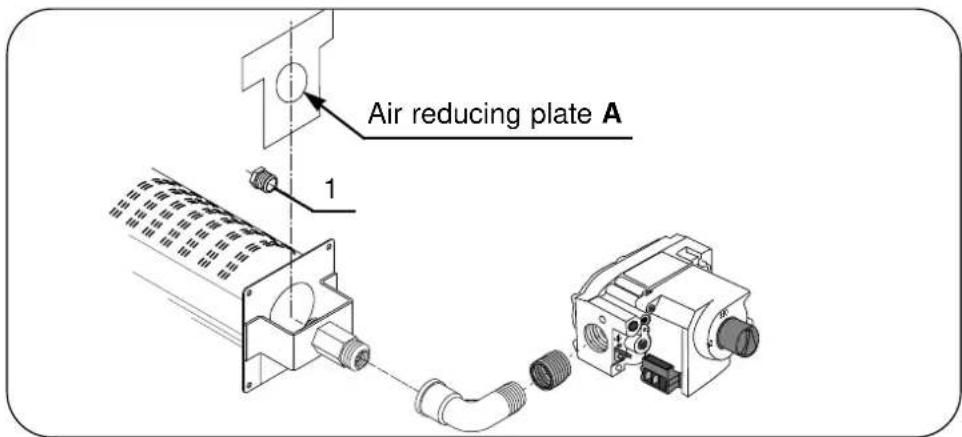
| Dryer type | Heating power Btu/h | Gas type Upper | Upper Gas pressure calorific value index 2 1 MJ/m3 MJ/m3 inch | ∅ Nozzle W.C. inch W.C. mm | Nozzle pressure (Outlet pressure tap) 5 mm | ||
| Type 30 | 71600 | LPG | 125.81 | 87.33 | 11.0 | 11.0 | 2.2 |
| GNH | 37.78 | 50.72 | 7.0 | 4.2 | 3.8 | ||
| Type 50 | 136400 | LPG | 125.81 | 87.33 | 11.0 | 11.0 | 3.2 |
| GNH | 37.78 | 50.72 | 7.0 | 3.2 | 5.6 | ||
| Type 75 | 151200 | LPG | 125.81 | 87.33 | 11.0 | 11.0 | 3.5 |
| GNH | 37.78 | 50.72 | 7.0 | 3.2 | 5.8 | ||
The programming mode is used for changing (programming) preset machine values
At the factory, the dryer has been set to specific values for: Time, temperature, cooling, reversing, etc. These values can be adjusted in the programming mode.
The parameters must always match to the specific dryer type.
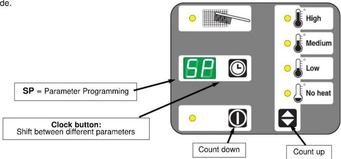
The machine parameters can be changed by switching the electronic control to Programming mode. The display will read SP and the three push-buttons will now be used to change the programming parameters, (see next page).

Programming is only to be carried out by qualified personnel.

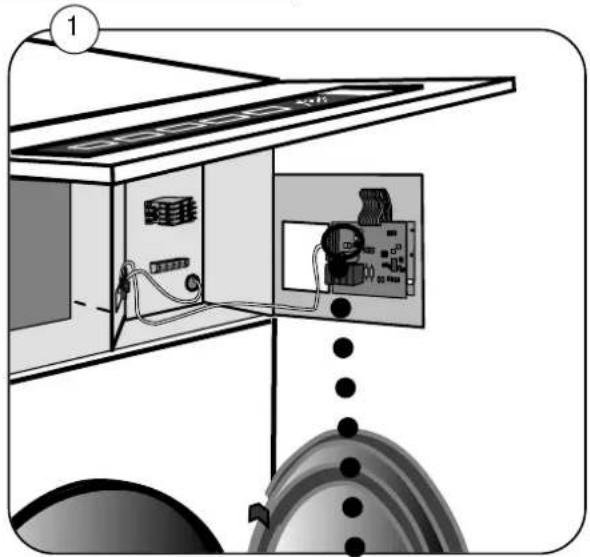
Switching to Programming mode
- Open the loading door (the door must be kept open).
1
- Open the door of the control panel.
2
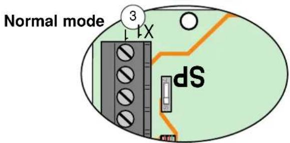
- Move the switch on the circuit-board to position SP, fig. 2.
- Program the dryer as described on following pages.
3
- End of programming. Move the switch back to normal mode, fig. 3.
natural_image
Diagram of an electrical enclosure with internal components and wiring, no visible text or symbols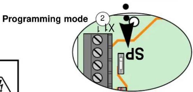
Caution

The control circuit board in this dryer contains hazardous voltages. Refer servicing to qualified personnel.

Note !! If Programming is activated when the machine power is subsequently switched on, a test and diagnosis program will start.
Adjustable parameters:
- Machine type
01.-03. Temperature - Temperature hysteresis
- Time interval
- Max. running time
- Running time between reversals
- Cooling time
09.-11. Residual moisture levels
12.-14. Extra drying time
Control panel function in Programming mode
Control panel switched to Programming mode.
Change of machine type
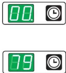
Press the clock button; the display will read 00., which is the first parameter (first parameter 00. = machine type).
The parameter numbers are shown for two seconds with a dot after the last digit.
After two seconds the machine type selected will be displayed. In this case, where the display reads 79, the machine is the Aqua Clean dryer with reversing.
Change of machine type, continued
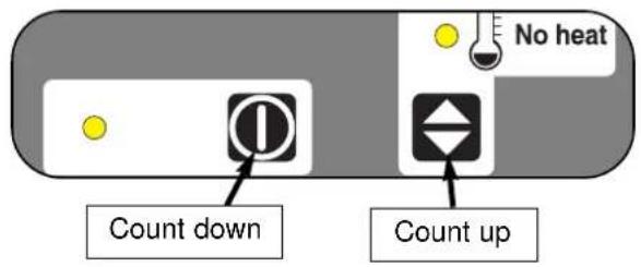
The machine type can be changed by using the buttons to count up or down.
Change of parameters
When the machine type has been selected, push the clock button; parameter no. 01 will come up on the display: After two seconds a value is shown that can be changed by means of the count up/down buttons.
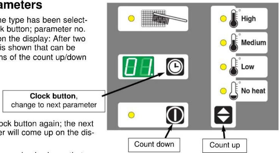
Now press the clock button again; the next parameter number will come up on the display.
After two seconds a value is shown that can be changed by means of the count up/down buttons, etc....
It is possible to scroll the parameters by pushing the clock button repeatedly.
Note! Parameter 06. = maximum running time for a manual machine. If maximum running time on a manual machine is changed e.g. to 30 minutes, the machine cannot run more than the maximum time, i.e. 30 minutes.
Parameter programming
| Parameter no.check by pressingthe clock button | Valuecan be set after two seconds | Required change: Press the “count up/down” buttons. |
Temperature setting
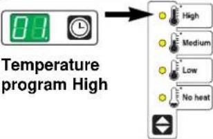 | The highest temperature can be set to a value between 32°C-85°C. Factory setting = 85 (=185°F) 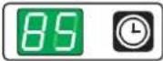 | 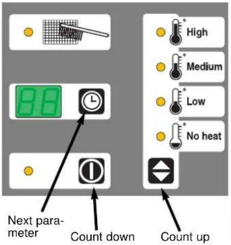 Temperature conversion °C......°F 32......90 38......100 43......110 49......120 54......130 60......140 71......160 85......185 Temperature conversion °C......°F 32......90 38......100 43......110 49......120 54......130 60......140 71......160 85......185 | |
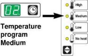 | The medium temperature can be set to a value between 32°C-85°C. Factory setting = 70 (=158°F) 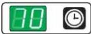 | ||
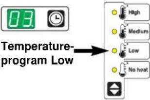 | Lowest temperature can be set to a value between 32°C-85°C. Factory setting = 50 (=122°F) 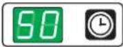 | ||
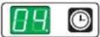 Temperature hysteresis Temperature hysteresis | Difference between heat on or off | Can be set to a value between 01°C-10°C. Factory setting = 02 (=3.6°F) 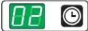 | |
Time setting
______ Running time 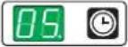 per pushTime interval per pushTime interval | Can be set to a value between 0.1 and 90 minutes. Factory setting = 3.0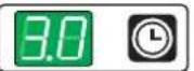 | From 0.1 to 9.9 minutes the setting can be changed by increments of 1/10 minute per push.From 10 to 90 minutes the setting can be changed by increments of 1 minute per push. |
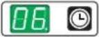 Max. running time Max. running time | Can be set to a value between 0.1 and 90 minutes. Factory setting = 45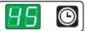 | From 0.1 to 9.9 minutes the setting can be changed by increments of 1/10 minute per push.From 10 to 90 minutes the setting can be changed by increments of 1 minute per push. |
Reversing
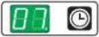 Running time between reversals Running time between reversals | Can be set to a value between 0.1 and 9,9 minutes. Factory setting = 5.0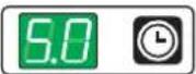 | Change the setting by 1/10 minute per push. |
Parameter programming
| Parameter no.check by pressingthe clock button | Valuecan be set after two seconds | Required change: Press the“count up/down” buttons. |
Cooling time
| Cooling time | Running timewithoutheat at end ofcycle | Can be set to a valuebetween 00 and 10 minutes.Factory setting = 03 | Count down Count up |
Residual moisture level
The measurement of residual moisture level consists of a combined parameter set for residual moisture + a parameter for extra drying time.
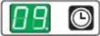 Program A1 Program A1 | Residual moisture level | Can be set to a value between 05 and F0. Factory setting F0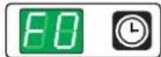 | The values for residual moisture are given in hexadecimals (05-F0). See explanation on following page. |
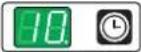 Program A2 Program A2 | Residual moisture level | Can be set to a value between 05 and F0. Factory setting 70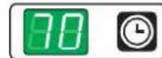 | |
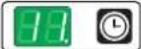 Program A3 Program A3 | Residual moisture level | Can be set to a value between 05 and F0. Factory setting 30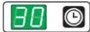 |
Extra drying time
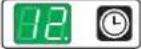 Program A1 Program A1 | Extra drying timein minutes | Can be set to a value between 00 and 20 minutes.Factory setting 03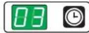 | Extra drying time when the value set in parameter 09 has been reached. |
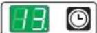 Program A2 Program A2 | Extra drying timein minutes | Can be set to a value between 00 and 20 minutes.Factory setting 00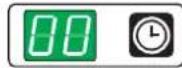 | Extra drying time when the value set in parameter 10 has been reached. |
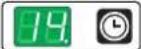 Program A3 Program A3 | Extra drying timein minutes | Can be set to a value between 00 and 20 minutes.Factory setting 00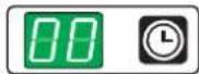 | Extra drying time when the value set in parameter 11 has been reached. |
Residual moisture level
Measurement principle
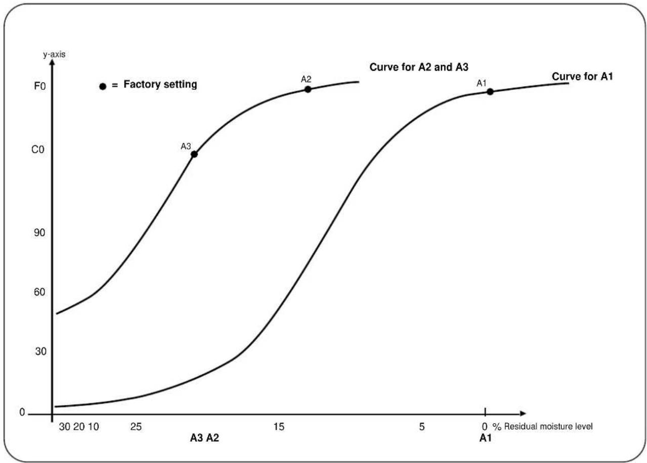
line
| A1 (%) | y-axis (Curve for A2) | y-axis (Curve for A3) | |--------|------------------------|------------------------| | 30 | ~55 | ~0 | | 20 | ~65 | ~10 | | 10 | ~75 | ~20 | | 25 | ~85 | ~30 | | 15 | ~95 | ~40 | | 10 | ~98 | ~50 | | 5 | ~99 | ~60 | | 0 | ~100 | ~70 | | 0 | Curve for A1 | Curve for A2 | | 0 | Curve for A3 | Curve for A3 |Explanation of Y-axis (hexadecimal)
The values for residual moisture are shown in the display in so-called hexadecimal format - a series of numbers covering a total of 16 values for each digit (0,1,2,3, . . . . .9,A,B,C,D,E,F). A total of 236 values can be shown in two digits.
If the clothes are not dry enough, add increments by using the "count up" button.
Total: 236 increments

Quick-view parameter list
The following values are factory settings
| Parameter-number | Value/setting | Parameter |
| 00. 79 | Machine type, | Aqua Clean |
| 01. 85 | Program with high temperature (85°C = 185°F) | |
| 02. 70 | Program with medium temperature (70°C = 158°F) | |
| 03. 50 | Program with low temperature (50°C=122°F) | |
| 04. 02 | Temperature hysteresis | |
| 05. 3.0 | Time interval, running time pr push | |
| 06. 45 | Max. time | |
| 07. 5.0 | Running time between reversals | |
| 08. 03 | Cooling time | |
| 09. F0 | Moisture level: | A1 |
| 10. 70 | Moisture level: | A2 |
| 11. 30 | Moisture level: | A3 |
| 12. 03 | Extra drying time: | A1 |
| 13. 00 | Extra drying time: | A2 |
| 14. 00 | Extra drying time: | A3 |
- Operating and installation manual
- TD30 RMC - TD50 RMC - TD75 RMC
- Aqua Clean
- Gas dryers only
- OPERATING & MAINTENANCE MANUAL Tumble dryer Type 30 - Type 50 - Type 75
- NOTICE TO: OWNERS, OPERATORS AND DEALERS OF WASCOMAT MACHINES.
- SAFETY AND WARNING SIGNS
- Replace If Missing Or Illegible
- INSTALLATION AND MAINTENANCE WARNINGS
- IMPORTANT
- SAFETY AND WARNINGS SIGNS
- WARNING
- MISE EN GARDE
- CAUTION
- INSTRUCTIONS
- FOR YOUR SAFETY
- Electrical Information
- Electric Service Gas dryers ONLY
- Gas Information
- Gas Supply
- Technical Gas Data
- Natural Gas
- Liquid Petroleum (L.P.) Gas
- Piping/Connections
- Contents:
- Safety instructions
- Diagram of tumble dryer
- Manual operation with RMC (residual moisture control)
- Aqua Clean wash and drying programs
- Error codes
- F1 = Machine type has not been set.
- F4 = The thermal sensor is disconnected.
- Running hours counter
- Example of machine having run for 12796 hours:
- Maintenance
- Daily
- Quarterly/Semi-annually
- Maintenance continued
- Annually
- Lubrication
- Setup, type 30 and 50
- Unpacking
- Positioning
- Mechanical installation
- Setup, type 75
- Reversing the door
- Dryer door reversal instructions
- Tumble dryer inlet air requirements
- Fresh- air
- Air principle
- Tumble dryer exhaust system
- Exhaust system for installation of several machines with a shared exhaust duct
- Exhaust duct
- Mashine Dimensions
- Installation - gas heating
- Electrical installation: Gas heating
- Connecting the power cable:
- Cable dimension:
- Function check see next page
- Electrical installation
- Function check
- Start the machine.
- Electrical installation - Tumble dryer type 30
- Electrical installation - Tumble dryer type 50
- Electrical installation - Tumble dryer type 75
- Gas installation
- Test run
- To convert from one gas to another:
- Start-up
- Gas control knob settings
- Gas valve
- Gas installation - tumble dryer type 30, 50 and 75
- The programming mode is used for changing (programming) preset machine values
- Switching to Programming mode
- Adjustable parameters:
- Control panel function in Programming mode
- Change of machine type
- Change of machine type, continued
- Change of parameters
- Parameter programming
- Temperature setting
- Time setting
- Reversing
- Residual moisture level
- Explanation of Y-axis (hexadecimal)
- Quick-view parameter list
Brand : Wascomat
Model : TD50 RMC
Category : Tumble dryer