Active 100 - Elliptical bike York Fitness - Free user manual and instructions
Find the device manual for free Active 100 York Fitness in PDF.


| Product Type | Elliptical Cross Trainer |
| Brand | York Fitness |
| Model | Active 100 |
| Maximum User Weight | 100 kg (220 lbs) |
| Resistance Type | Manual tension control knob (8 levels) |
| Display | LCD with 6 functions (Time, Speed, Distance, Calories, Odometer, Pulse) |
| Power Supply | 2 x AAA/UM-4 batteries (not included) |
| Scan Mode | Auto-scan every 6 seconds |
| Pulse Measurement | Hand contact sensors on handlebars |
| Target Setting | Time, Distance, Calories (countdown mode) |
| Auto Shut-off | After 4 minutes of inactivity |
| Foot Pedals | Large, adjustable with anti-slip surface |
| Handlebar | Multi-position with foam grips |
| Assembly Required | Yes – includes Allen keys and wrenches |
| Dimensions (approx.) | 120 x 60 x 150 cm (47 x 24 x 59 in) |
| Weight (approx.) | 35 kg (77 lbs) |
| Warranty | 1 year parts (domestic use) |
| Cleaning | Wipe with damp cloth after each use; avoid solvents |
| Intended Use | Indoor home use only |
Frequently Asked Questions - Active 100 York Fitness
User questions about Active 100 York Fitness
0 question about this device. Answer the ones you know or ask your own.
Ask a new question about this device
Download the instructions for your Elliptical bike in PDF format for free! Find your manual Active 100 - York Fitness and take your electronic device back in hand. On this page are published all the documents necessary for the use of your device. Active 100 by York Fitness.
USER MANUAL Active 100 York Fitness
natural_image
Line drawing of an outdoor fitness bike with leg, arms, and wheels (no text or symbols)TABLE OF CONTENTS
SAFETY PRECAUTIONS 2 7-8 PRE-ASSEMBLY CHECK LIST HARDWARE PACKING LIST 4 PARTS LIST
EXPLODED DIAGRAM 3 ASSEMBLY INSTRUCTIONS . 9-14 CONSOLE INSTRUCTIONS 15-16 5-6 EXERCISE INSTRUCTIONS 17-18 SERVICE 19 - 21
IMPORTANT SAFETY PRECAUTIONS
This exercise machine is built for optimum safety. However, certain precautions apply whenever you operate a piece of exercise equipment. Be sure to read the entire manual before you assemble or operate your machine. In particular, note the following safety precautions:
- Keep children and pets away from the machine at all times. DO NOT leave children unattended in the same room with the machine.
- Only one person at a time should use the machine.
- If the user experiences dizziness, nausea, chest pain, or any other abnormal symptoms, STOP the workout at once. CONSULT A PHYSICIAN IMMEDIATELY.
- Position the machine on a clear, leveled surface. DO NOT use the machine near water or outdoors.
- Keep hands away from all moving parts.
- Always wear appropriate workout clothing when exercising. DO NOT wear robes or other clothing that could become caught in the machine. Running or aerobic shoes are also required when using the machine.
- Use the machine only for its intended use as described in this manual. DO NOT use attachments not recommended by the manufacturer.
- Do not place any sharp objects around the machine.
- Disabled persons should not use the machine without a qualified person or physician in attendance.
- Before using the machine to exercise, always do stretching exercises to properly warm up.
- Never operate the machine if the machine is not functioning properly.
- The max. user capacity is 100 KGS.
WARNING: BEFORE BEGINNING ANY EXERCISE PROGRAM, CONSULT YOUR PHYSICIAN. THIS IS ESPECIALLY IMPORTANT FOR INDIVIDUALS OVER THE AGE OF 35 OR PERSONS WITH PRE-EXISTING HEALTH PROBLEMS. READ ALL INSTRUCTIONS BEFORE USING ANY FITNESS EQUIPMENT.
SAVE THESE INSTRUCTIONS
PLEASE KEEP A COPY OF YOUR PURCHASE RECEIPT WITH THIS MANUAL
PRE-ASSEMBLY CHECK LIST
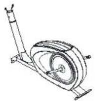 NO. 1 NO. 1 | 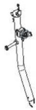 NO. 2 NO. 2 | 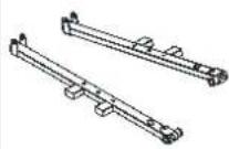 NO. 3L/R NO. 3L/R | 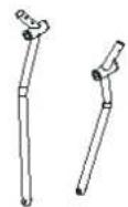 NO. 4L/R NO. 4L/R |
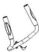 NO. 5 NO. 5 | 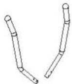 NO. 7L/R NO. 7L/R | 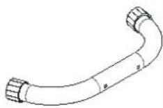 NO. 8 NO. 8 | 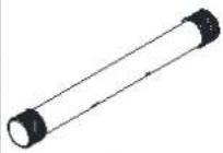 NO. 9 NO. 9 |
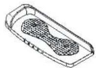 NO. 44 NO. 44 | 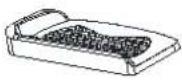 NO. 45 NO. 45 | 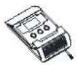 NO. 46 NO. 46 |
| PART NO. | DESCRIPTION | Q'TY |
| 01 | Main frame | 1 |
| 02 | Front support | 1 |
| 03L/R | Pedal tube L/R | 1/1 |
| 04L/R | Bottom handlebar L/R | 1/1 |
| 05 | Handlebar | 1 |
| 07L/R | Top handlebar L/R | 1/1 |
| 08 | Front stabilizer | 1 |
| 09 | Rear stabilizer | 1 |
| 44 | Pedal tube L | 1 |
| 45 | Pedal tube R | 1 |
| 46 | Console | 1 |
HARDWARE PACKING LIST
| NO. | DESCRIPTION | QTY | DRAWING | |
| 14 | Hollow carriage screw φ7.8x27L | 4 | 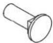 14 14 | 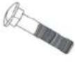 15 15 |
| 15 | Carriage bolt M8x60L | 4 | ||
| 17 | Allen screw M6x15L | 4 | 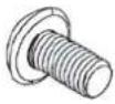 17 17 | 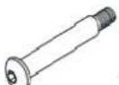 18L 18L |
| 18L | Allen bolt φ15.8x97L | 1 | ||
| 18R | Allen bolt φ15.8x97L | 1 | 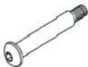 18R 18R |  19 19 |
| 19 | Allen screw M8x30L | 2 | ||
| 21 | Hex head bolt M10x55L | 2 | 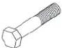 21 21 | 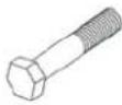 22 22 |
| 22 | Hex head screw M8x40L | 4 | ||
| 24 | Cover for handlebar post | 1 |  24 24 |  27 27 |
| 27 | PVC cap | 6 | ||
| 28 | PVC cap | 4 |  28 28 |  29 29 |
| 29 | Spring washer M8 | 2 | ||
| 30 | Spring washer φ13 | 2 |  30 30 | [zkay]32 |
| 32 | Wave washer | 2 | ||
| 33 | Flat washer φ10.2xφ19x1.2t | 2 | 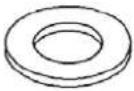 33 33 | 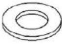 35 35 |
| 35 | Flat washer φ8.5xφ16x1.5t | 4 | ||
| 36 | Curved washer φ8.5xφ20x1.5t | 4 |  36 36 |  38 38 |
| 38 | Nylon nut M8 | 4 | ||
| 39 | Nylon nut M10x8t | 2 |  39 39 |  40 40 |
| 40 | Nylon nut L | 1 | ||
| 41 | Nylon nut R | 1 |  41 41 |  42 42 |
| 42 | Domed nut M8x16t | 4 | ||
| 86 | Allen key A | 1 | [yy3]86 | 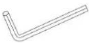 87 87 |
| 87 | Allen key B | 1 | ||
| 88 | Box wrench | 1 | 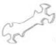 88 88 | 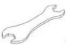 89 89 |
| 89 | Double open-end wrench | 1 | ||
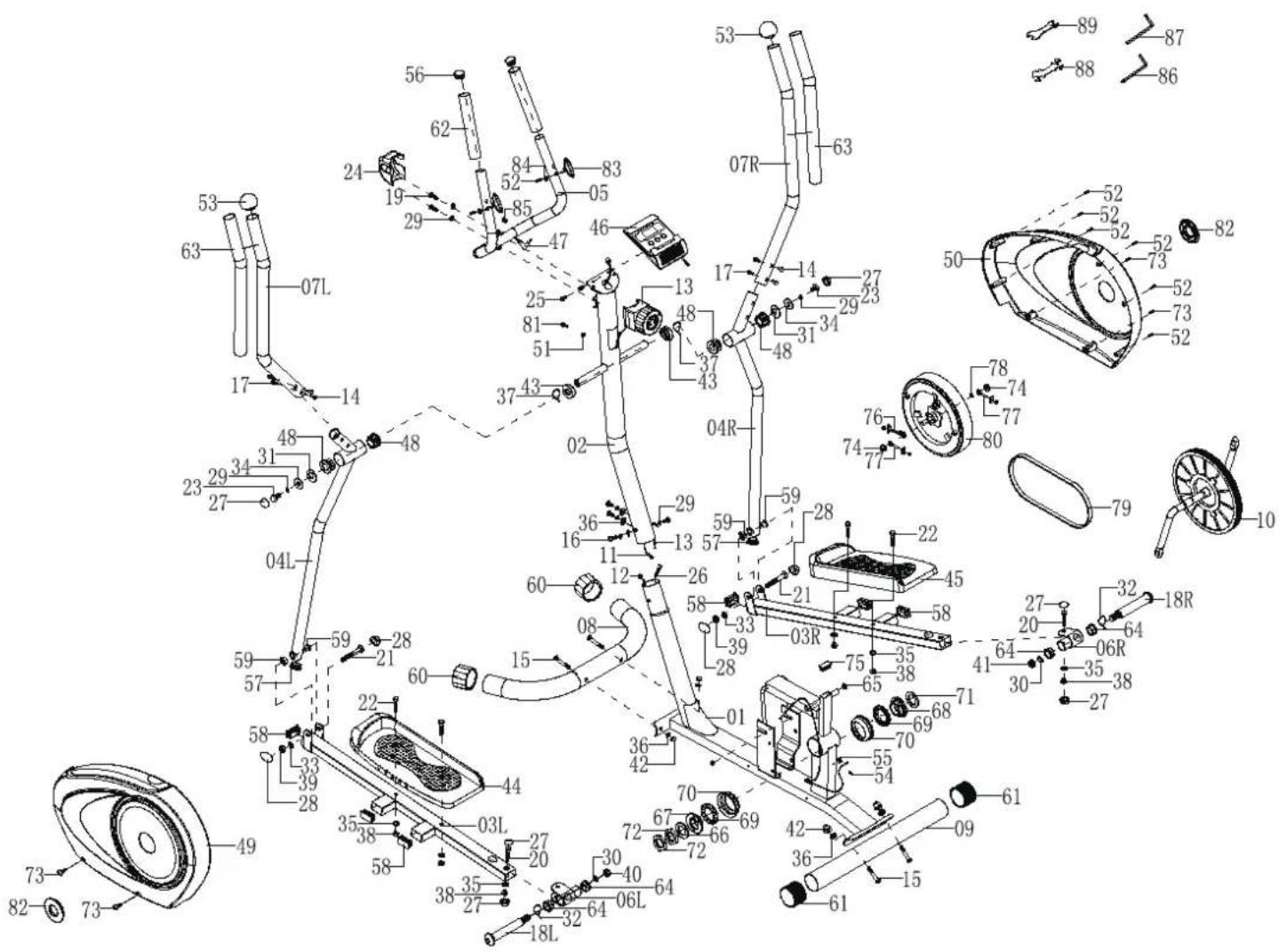
PARTS LIST
| Item No. | Description | Q'ty | Item No. | Description | Q'ty |
| 01 | Main Frame | 1 | 36 | Curved Washer Φ8.5xφ20x1.5t | 8 |
| 02 | Front Support | 1 | 37 | Wave Washer | 2 |
| 03 L | Pedal Tube L | 1 | 38 | Nylon Nut M8 | 6 |
| 03 R | Pedal Tube R | 1 | 39 | Nylon Nut M10x8t | 2 |
| 04L | Bottom Handlebar L | 1 | 40 | Nylon Nut L | 1 |
| 04R | Bottom Handlebar R | 1 | 41 | Nylon Nut R | 1 |
| 05 | Handlebar Post | 1 | 42 | Domed Nut M8x16t | 4 |
| 06L | U-Type Bracket L | 1 | 43 | Curved Washer | 2 |
| 06R | U-Type Bracket R | 1 | 44 | Pedal L | 1 |
| 07L | Top Handlebar L | 1 | 45 | Pedal R | 1 |
| 07R | Top Handlebar R | 1 | 46 | Console | 1 |
| 08 | Front Stabilizer | 1 | 47 | Upper Pulse Wire | 1 |
| 09 | Rear Stabilizer | 1 | 48 | Sleeve | 4 |
| 10 | Crank | 1 | 49 | Chain Cover L | 1 |
| 11 | Upper Sensor Wire | 1 | 50 | Chain Cover R | 1 |
| 12 | Lower Sensor Wire | 1 | 51 | Curved Washer Φ5.5xφ20x1.5t | 1 |
| 13 | Tension Control Knob | 1 | 52 | Self Tapping Screw St4.2x20l | 8 |
| 14 | Hollow Carriage Screw Φ7.8x27l | 4 | 53 | End Cap For Top Handlebar | 2 |
| 15 | Carriage Bolt M8x60l | 4 | 54 | Self Tapping Screw M4x12l | 1 |
| 16 | Allen Screw M8x20l | 4 | 55 | Sensor Bracket | 1 |
| 17 | Allen Screw M6x15l | 4 | 56 | End Cap For Handlebar | 2 |
| 18L | Allen Bolt Φ15.8x97l | 1 | 57 | End Cap For Bottom Handlebar | 2 |
| 18R | Allen Bolt Φ15.8x97l | 1 | 58 | Square End Cap For Pedal Tube | 6 |
| 19 | Allen Screw M8x30l | 2 | 59 | Plastic Spacer | 4 |
| 20 | Hex Head Bolt M8x45l | 2 | 60 | End Cap For Front Stabilizer | 2 |
| 21 | Hex Head Bolt M10x55l | 2 | 61 | End Cap For Rear Stabilizer | 2 |
| 22 | Hex Head Screw M8x40l | 4 | 62 | Foam Grip For Handlebar | 2 |
| 23 | Hex Head Screw M8x15l | 2 | 63 | Foam Grip For Top Handlebar | 2 |
| 24 | Clamp Cover | 1 | 64 | Plastic Spacer | 4 |
| 25 | Screw For Console | 2 | 65 | End Cap | 2 |
| 26 | Extension Tension Cable | 1 | 66 | Washer | 1 |
| 27 | Pvc Cap | 6 | 67 | Bearing Bracket L | 1 |
| 28 | Pvc Cap | 4 | 68 | Bearing Bracket R | 1 |
| 29 | Spring Washer M8 | 8 | 69 | Ball Bearings | 2 |
| 30 | Spring Washer Φ13 | 2 | 70 | Bearing Bracket | 2 |
| 31 | D Type Washer | 2 | 71 | Washer | 1 |
| 32 | Wave Washer | 2 | 72 | Nut | 2 |
| 33 | Flat Washer Φ10.2xφ19x1.2t | 2 | 73 | Self Tapping Screw M4x20l | 4 |
| 34 | Flat Washer Φ8.5xφ26x2.0t | 2 | 74 | France Nut M10 | 2 |
| 35 | Flat Washer Φ8.5xφ16x1.5t | 6 | 75 | Square End Cap For Main Frame | 1 |
PARTS LIST
| Item No. | Description | Q'ty | Item No. | Description | Q'ty |
| 76 | Flywheel Adjust Set | 1 | 84 | Flat Washer | 2 |
| 77 | Flywheel Adjust Set | 2 | 85 | Grommet | 1 |
| 78 | Flat Washer | 1 | 86 | Allen Key A | 1 |
| 79 | Belt | 1 | 87 | Allen Key B | 1 |
| 80 | Magnet Assembly W Flywheel | 1 | 88 | Box Wrench | 1 |
| 81 | Screw M5x12L | 1 | 89 | Double Open-End Wrench | 1 |
| 82 | Cover For Crank | 2 | |||
| 83 | Hand Pulse Sensor | 2 | |||
EXPLODED DIAGRAM
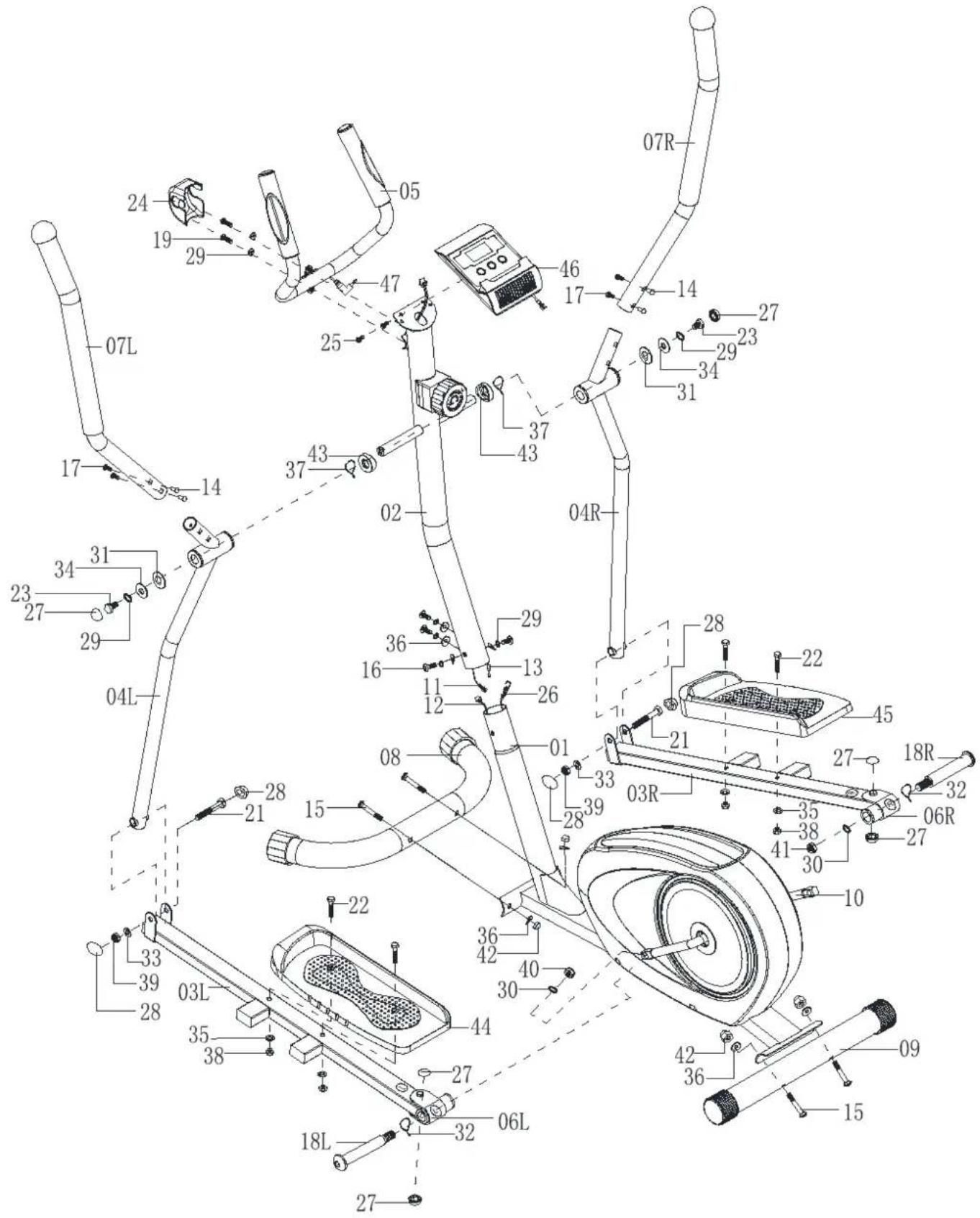
EXPLODED DIAGRAM
ASSEMBLY INSTRUCTIONS
STEP 1
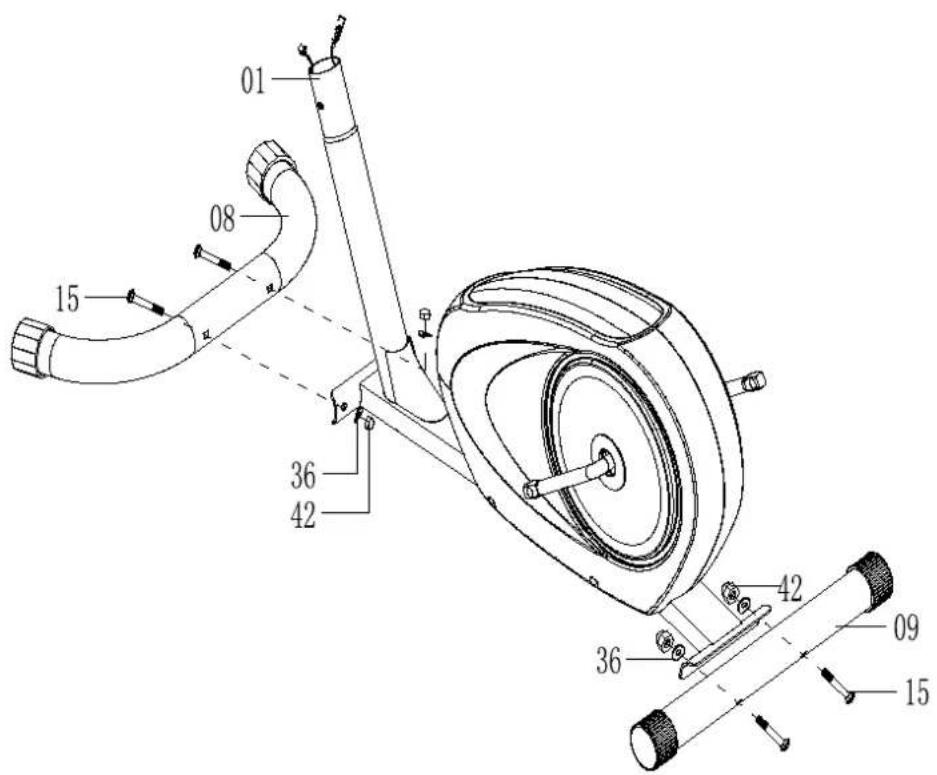
Attach the front stabilizer (8) to the front of the main frame (1) and fasten with two carriage bolts (15), two curved washers (36) and two domed nuts (42).
Attach the rear stabilizer (09) to the rear of the main frame and fasten with two carriage bolts (15), two curved washers (36) and two domed nuts (42).
STEP 2
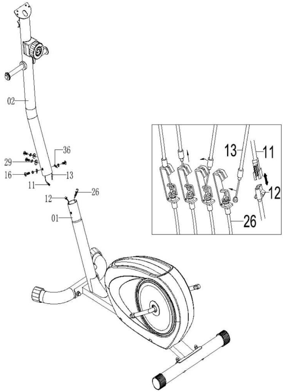
Connect the upper sensor wire (11) from the front support (02) to the lower sensor wire (12).
Turn the tension control knob (13) to level 8. Connect the tension control cable (13) from the front support (02) to the extension tension cable (26).
Insert the front support (02) into the main frame (1). Secure using four allen screws (16) and four spring washers (29) and four curved washers (36)
STEP 3
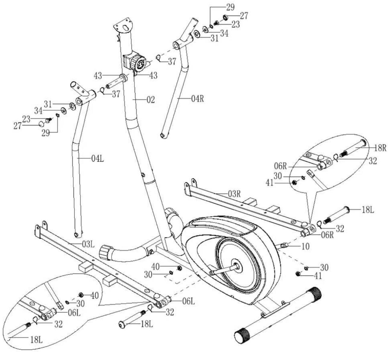
Attach the left bottom handlebar (04L) to the left side axle of the front support (02). Secure using one hex head screw (23), one spring washer (29), one flat washer (34) and one D type washer (31). Attach the PVC cap (27) onto the hex head screw (23).
Repeat for the right bottom handlebar (04R) to the right side axle of the front support (02).
Attach the left pedal tube (06L) to the left crank arm (10). Secure using left allen bolt (18L), one wave washer (32), one spring washer (30) and one nylon nut L(40).
Attach the right pedal tube (06R) to the right crank arm (10). Secure using right allen bolt (18R), one wave washer (32), one spring washer (30) and one nylon nut R (41).
STEP 4
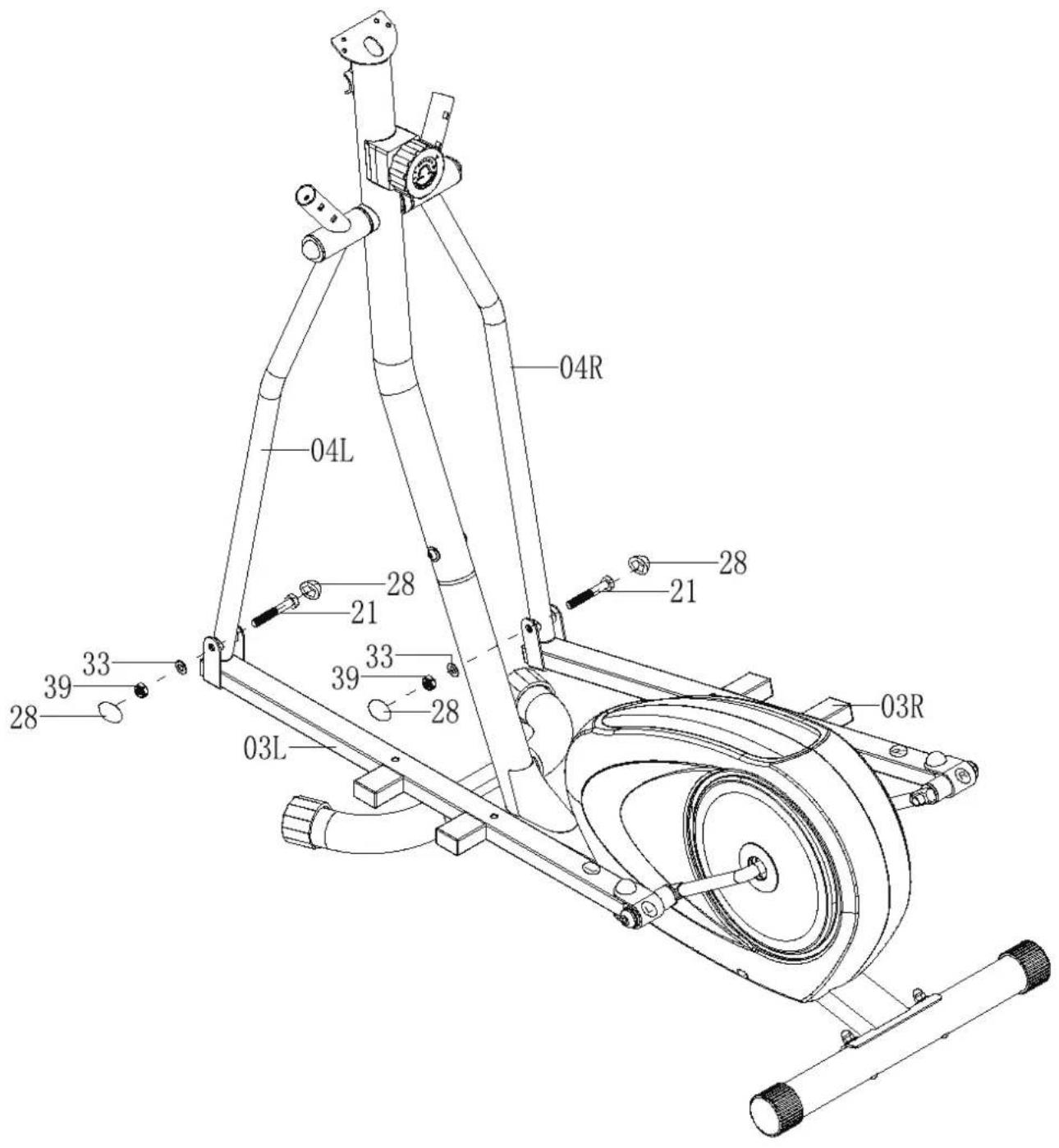
Attach the left pedal tube (03L) to the left bottom handlebar (04L). Secure using one hex head bolt (21), one flat washer (33) and one nylon nut (39) Attach the PVC cap (28) onto the hex head bolt (21).
Repeat for the right pedal tube (03R) to the right bottom handlebar (04R).
STEP 5
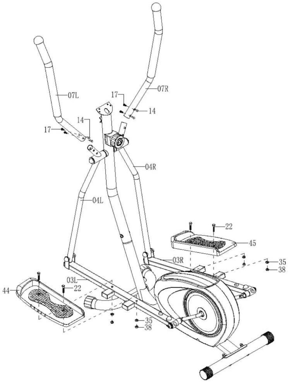
Connect the left top handlebar (07L) to the left bottom handlebar (04L). Secure using two hollow carriage bolts (14) and two allen bolts (17).
Repeat for the right top handlebar (07R) to the right bottom handlebar (04R).
Connect the left pedal (44) to the left pedal tube (03L). Secure using two hex head bolts (22) and two flat washers (35), two nylon nuts (38)
Repeat for the right pedal (45) to the right pedal tube (03R).
STEP 6
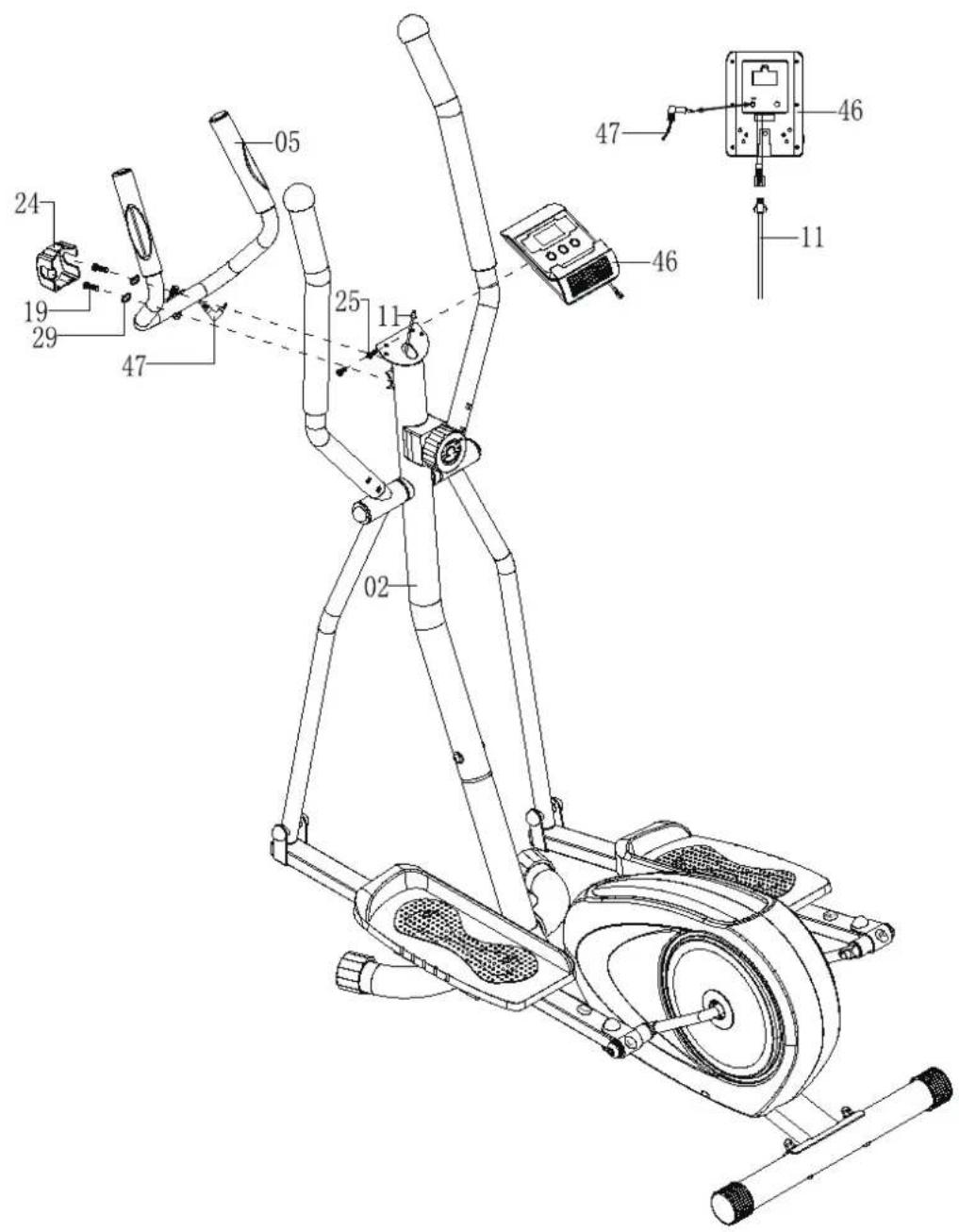
Attach the handlebar (05) to the front support (02). Secure using two allen screws (19) and two spring washers (29), clamp cover (24)
Thread the upper sensor wire (11) from the hole on the front support (02) and connect upper sensor wire (11) to the sensor wire from the back of console (46).
Attach the console (46) to the front support (02). Secure using two screw (25), plug the upper pulse wire into the back of console (46).
CONSOLE INSTRUCTIONS
natural_image
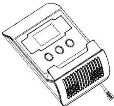
Line drawing of a handheld electronic device with buttons and a textured base (no text or symbols)FUNCTIONAL BUTTONS:
MODE - Push down for selecting functions.
SET - To set time, distance, calories and pulse.
RESET - To reset time, distance, calories and pulse.
FUNCTION AND OPERATIONS:
- SCAN: Press "MODE" button until "SCAN" appears. The monitor will rotate through all the functions: time, speed, distance, calories, odometer and pulse. Each display will be held for 6 seconds.
2.TIME: (1) Counts the total time from exercise start to end.
(2) Press "MODE" button until "TIME" appears, press "SET" button to set exercise time. Automatically counts down from target value during exercise.
3.SPEED: Displays current speed.
4.DISTANCE: (1) Counts the distance from exercise start to end.
(2) Press “MODE” but ton until “DIST” appears. Press “SET” but ton to set exercise distance. Automatically count down from target value during exercise.
5.CALORIES: (1) Counts the total calories from exercise start to end.
(2) Press “MODE” but ton until “CAL” a pears. P ress “SET” b utton to set exercise calories. A utomatically c ounts d own from target v alue during exercise.
6.ODOMETER: Monitor will display the total accumulated distance.
7.PULSE: Press MODE button until "PULSE" appears. Before measuring your pulse rate, please place the palms of your hands on both contact pads and the monitor will show your current heart beat rate in beats per minute(BPM) on the LCD after 6\~7 seconds.
Remark: During the process of pulse measurement, because of the contact jamming, the measurement value may be higher than the virtual pulse rate during the first 2\~3 seconds. It will then return to normal level. The measurement value can not be regarded as the basis of medical treatment.
NOTE:
-
If the display is faint or shows no figures, please replace the batteries.
-
The monitor will automatically shut off if there is no signal received after 4 minutes.
SPECIFICATIONS:
| FUNCTION | AUTO SCAN | Every 6 seconds |
| TIME 0:00'~99:59' | ||
| CURRENT SPEED | 0.0~999.9 KM/H | |
| TRIP DISTANCE 0.00~999.9 KM | ||
| CALORIES 0.0~999.9 CAL | ||
| ODOMETER 0.0 ~ 9999 KM | ||
| PULSE RATE 40~240 BPM | ||
| BATTERY TYPE | 2pcs of SIZE -AAA or UM -4 | |
| OPERATING TEMPERATURE | 0°C ~ +40°C | |
| STORAGE TEMPERATURE -10°C | ~ +60°C | |
EXERCISE INSTRUCTIONS
Using y our ELLIPTICAL T RAINER will provide you with several ben efits, i t w ill improve your physical f itness, t one muscle and i n c onjunction w ith a c alorie c controlled di et help y ou lose weight.
1. The Warm Up Phase
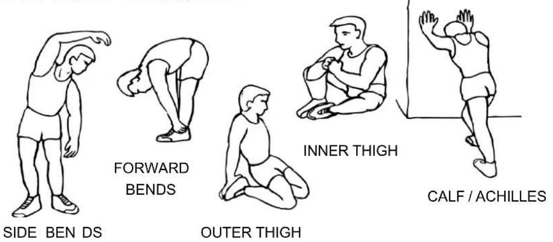
This stage helps get the blood flowing around the body and the muscles working properly. It will also reduce the risk of cramp and muscle injury. It is advisable to do a few stretching exercises as shown below. Each stretch should be held for approximately 30 seconds, do not force or jerk your muscles into a stretch - if it hurts, STOP.
2. The Exercise Phase
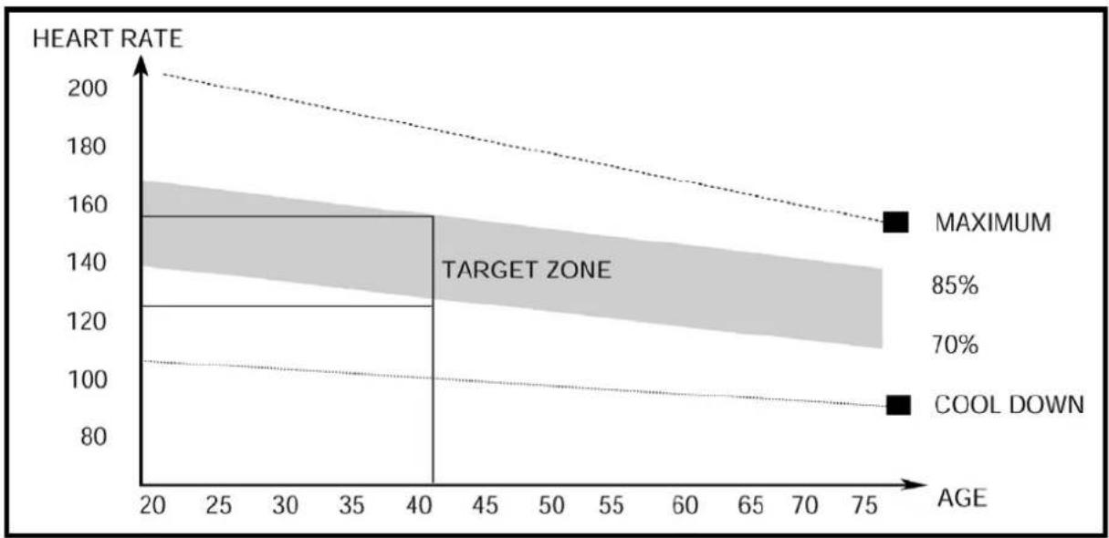
This is the stage where you put the effort in. After regular use, the muscles in your legs will become more flexible. Work to your best but it is very important to maintain a steady tempo throughout. The rate of work should be sufficient to raise your heart beat into the target zone shown on the graph below.
line
| AGE | HEART RATE | | --- | --- | | 20 | 200 | | 40 | 160 | | 75 | 140 |This stage should last for a minimum of 12 minutes though most people start at about 15-20 minutes
3. The Cool Down Phase
This stage is to let your cardio-vascular System and muscles wind down. This is a repeat of the warm up exercise e.g. reduce your tempo, continue for approximately 5 minutes. The stretching exercises should now be repeated, again remembering not to force or jerk your muscles into the stretch.
As you get fitter you may need to train longer and harder. It is advisable to train at least three times a week, and if possible space your workouts evenly throughout the week.
MUSCLE TONING
To tone muscle while on your ELLIPTICAL TRAINER you will need to have the resistance set quite high. This will put more strain on your leg muscles and may mean you cannot train for as long as y ou w ould like. If y ou are al so t rying t o i mprove y our f itness y ou n eed t o alter training program. You should t rain as nor mal dur ing the warm up and c ool down phas es, but towards the end of the exercise phase you should increase resistance making your legs work harder. You will have to reduce your speed to keep your heart rate in the target zone.
WEIGHT LOSS
The important factor here is the amount of effort you put in. The harder and longer you work the more calories you will burn. Effectively this is the same as if you were training to improve your fitness, the difference is the goal.
BOYLES BFE FITNESS EQUIPMENT
WARRANTY, SAFETY AND ASSEMBLY INFORMATION
YORK ACTIVE 100 CROSS TRAINER
YRK52086A
IMPORTANT
Please read and retain this informaon as it will assist with idencaon for parts and services.
BOYLES FITNESS warrants their Ellipcal to be free from defects in material and workmanship under normal use and service conditions.
The various components of the Ellipcal are warranted against defects and workmanship for the me periods specied as follows:
Domesc use
1 year parts
All warranty coverage extends only to the original retail purchase from the date of purchase. BOYLES FITNESS' obligaon under this Warranty is limited to replacing or repairing, at BOYLES opon, the product or parts therein. Any enquiries relang to warranes or spare parts must be directed to Spares@bfe.com.au.
For ecient processing of your enquiry please have relevant date of purchase, retailer name you purchased the item from and the serial number. This warranty does not extend to any damage to a product caused by abuse, improper or abnormal usage (as detailed in this instrucon manual), or repairs not provided by BOYLES. Nor does this warranty extend to products used for commercial or rental purposes. This warranty does not cover ordinary wear, tear and weathering, failure to follow direcons, improper installaon, improper maintenance or acts of god (such as damage caused by storms, lightening and by snow or ice). No other warranty beyond that specially set forth above is authorized by BOYLES.
Our sales and service centre has been set up to provide assembly assistance, replacement parts and accessories, and to eciently handle all warranty related maers.
Hours 8:00am-3:00pm Mon-fri (excluding public holidays).
Service email: Spares@bfe.com.au
Website: www.yorkfitness.com.au
- When purchased from an authorised BFE distributor the BFE warranty shall guarantee that all framework and components of your product are free from faulty manufacture. All faulty framework and components will be repaired or replaced as set out in this policy. All warranes in this policy apply to INDOOR HOME/DOMESTIC USE ONLY.
- These warranes do not apply to products used in commercial use applicaons.
- Warranty DOES NOT cover normal wear & tear and excludes faults due to misuse, abuse, incorrect assembly or lack of general maintenance.
- Warranty is applicable to products sold and placed within Australia only.
- IMPORTANT. Most of BFE products are pretested and we have inspectors checking all products prior to shipment. The number one reason for a fault is due to INCORRECT ASSEMBLY.
If you do have problems please go back to the start and double check your assembly and pay special aenon to all WIRING conncons. If you have accidentally cut or damaged the wiring please let us know and we will be happy to send you a new set at no-charge.
If you have done this and are condent you have double checked your assembly and are sll having problems please email our service department at spares@bfe.com.au including your best contact details,proof of purchase, serial number and a brief explanaon of what is wrong.
Emailing is the quickest and most reliable way to get your service request processed. Once we have your details we will either call or email you back with the next steps. The quickest way, once we determine the problem and send you a replacement part, is that we can talk you through over the phone on how to t it.
If it is deemed by our service tech that it is too dicult, we can arrange (where available) a service technician.
NOTE. If we arrange for a service technician (where applicable) and it is found that it is not a manufactures fault and found to be an assembly issue, normal wear and tear, transport damage or misuse then there will be a call out fee of \$140 depending on locaon. (Surcharge applies for non-metro areas)
WARRANTY TERMS- Warranty commences from the date of purchase from the retail store. Warranty only applies to the original purchaser and is NON transferable. Warranty is void if the serial number of the product has been removed or tampered with.
Warranty does not apply to defects, faults or failures due to:
(a) Defects caused during assembly or failure to assemble to the assembly manual provided. Assembly errors include but are not limited to damaged wiring harness, stripped crank arms and or pedals and bolts used in the wrong locaons.
(b) Lack of general maintenance and or failure to service or maintain the equipment in accordance with the user manual speciaons and recommendaons.
(c) Power Surges. The computers, control boards and motors are very sensitive to power octuaons. You must use a surge protector on all items that plug into your mains power otherwise your electronics will not be covered by this warranty. You can purchase these from numerous retailers.
(d) User negligence, abnormal or excessive use, misuse, abuse or transport damage.
(e) Repairs, alteraons or modicaons by NON BFE authorised service technician.
(f) Accident, re, ood or malicious damage by third person.
(g) Ordinary wear and tear.
(h) Failure to keep the product in a clean, dry environment causing rust. You should wipe o any sweat and moisture aer each training session.
(i) Any products sold or placed in an applicaon or the incorrect environment that is not recommended by BFE or as not spulated in the owner's manual such as a commercial / rental environment will void the warranty set forth by BFE
(j) BFE recommends the use of a protecve rubber oor mat. This reduces the incidence of dust and lint collecon around the motor, reduces noise & protects your oor. You can purchase this from your retailer or contact BFE directly at sales@bfe.com.au
BFE will have the opon to repair or replace any product which requires aenon under the warranty.
NOTE: Lifetime refers to the warranty coverage of the units expected service life. NOT the lifetime of the purchaser.
Servicing/Spare Parts- As with any mechanical equipment general maintenance should be performed on a regular basis by an authorised retailer or service technician. This will ensure longevity of the product and ensure that it is kept working in opmum condition. Failure to properly maintain your equipment may lead to safety issues and may also void the warranty.
You should only use genuine BFE replacement parts otherwise the warranty will be void.
Freight Costs:
The cost of freighing the replacement part under warranty to the customer shall be free of charge. Your requirement is to return the faulty part via the pre-paid postal service which we will supply.
Returned Goods:
The unauthorised return of parts or product shall be refused and placed in the hands of the carrier at the cost of the shipper.
Return authorisaons can be obtained from BFE head oce only.
Additional Warranty
If you would like to extend your labour warranty by 1 year (\99), 2 years (\199), 3 years (\$299) please contact our oce by emailing sales@bfe.com.au (Not available in all areas)
Service Department hours: Monday to Friday between 8am and 3pm
Email: spares@bfe.com.au
PLEASE NOTE: that Authorised service technicians do not reside in all areas of this vast country. If you live beyond the reasonable service area of a metropolitan area, BFE may not be able to support the labour poron of the product warranty. Alternatively you can return (at your cost) your product to the closest BFE repair centre, where it will be xed at no charge under the warranty period.
Metropolitan Area- dened as no more that 50km from G.P.O in all capital cies.
Disclaimer:
Our goods come with guarantees that cannot be excluded under the Australian Consumer Law. You are entled to a replacement or refund for a 'Major failure' and for compensation for any other Reasonable foreseeable loss or damage.
You are also entled to have goods repaired or replaced if the goods fail to be of an acceptable quality and the failure does not amount to a major failure.
BFE does not assume, nor authorise any representave or other person to make or assume for BFE, any warranes whatsoever, whether expressed or implied, in, in conncon with the sale, service, or shipment of our products.
BFE reserve the right to make changes and improvements in our products and speciaons without incurring any obligaon to similarly alter products previously purchased.
This warranty operates in addition to other rights and remedies available to consumer's rights under the Australian Consumer Law.
Service Department hours: Monday to Friday between 8am and 3pm
Email: spares@bfe.com.au
- TABLE OF CONTENTS
- IMPORTANT SAFETY PRECAUTIONS
- PRE-ASSEMBLY CHECK LIST
- EXPLODED DIAGRAM
- ASSEMBLY INSTRUCTIONS
- STEP 1
- STEP 2
- STEP 3
- STEP 4
- STEP 5
- STEP 6
- CONSOLE INSTRUCTIONS
- FUNCTIONAL BUTTONS:
- FUNCTION AND OPERATIONS:
- NOTE:
- EXERCISE INSTRUCTIONS
- The Warm Up Phase
- The Exercise Phase
- The Cool Down Phase
- MUSCLE TONING
- WEIGHT LOSS
- BOYLES BFE FITNESS EQUIPMENT
- IMPORTANT
- Domesc use
- Freight Costs:
- Returned Goods:
- Additional Warranty
Brand : York Fitness
Model : Active 100
Category : Elliptical bike