
S-OV72000 - Cooker THETFORD - Free user manual and instructions
Find the device manual for free S-OV72000 THETFORD in PDF.


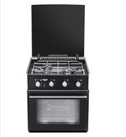
| Product Type | Gas oven (no hob) |
| Brand | Thetford |
| Model | S-OV72000 |
| Dimensions (HxWxD) | 408 x 527 x 530 mm |
| Weight | 13.5 kg |
| Oven Capacity | 32.4 litres (209 x 428 x 362 mm) |
| Energy Source | LPG (Butane or Propane) |
| Gas Pressure (Butane/Propane) | 30 mbar / 30 mbar |
| Electrical Supply | 12V dc, 150 mA, 1.8 W |
| Oven Heat Input | 1.6 kW |
| Temperature Range | 130°C to 240°C (Gas Mark 1/4 to 9) |
| Ignition | 12V Electronic spark ignition (optional) |
| Safety Features | Flame failure device (thermocouple) |
| Door Type | Slide-under oven door |
| Cooling System | Automatic fan cooling system (12V) |
| Shelf Positions | 3 oven positions (top, middle, bottom) |
| Suitable Installations | Caravans, motorhomes, boats, holiday homes |
| Important Restriction | Not for rooms with bath or shower; not below ground level |
| Recommended Gas | Propane for best performance |
| First Use | Heat oven at gas mark 5 for 30 minutes to remove residues |
| Cleaning | Warm soapy water; do not use abrasive cleaners |
| Repairable Parts | Burner injectors, thermocouple, control knob, thermal switches, spark electrode |
Frequently Asked Questions - S-OV72000 THETFORD
User questions about S-OV72000 THETFORD
0 question about this device. Answer the ones you know or ask your own.
Ask a new question about this device
Download the instructions for your Cooker in PDF format for free! Find your manual S-OV72000 - THETFORD and take your electronic device back in hand. On this page are published all the documents necessary for the use of your device. S-OV72000 by THETFORD.
USER MANUAL S-OV72000 THETFORD
USER AND INSTALLATION INSTRUCTIONS
PLEASE READ THOROUGHLY AND KEEP FOR FUTURE REFERENCE
FOR USE IN
GB, CH, ES, PT, IT, BE, FR, IE, DK, FI, GR, NL, NO, DE, SE, SL
SPINFLO LIMITED (Part of the Thetford Group)
Unit 19, Oakham Drive, Parkwood Industrial Estate
Rutland Road, Sheffield S3 9QX, ENGLAND.
TEL: +44 (0) 114 273 8157 FAX: +44 (0) 114 275 3094

IMPORTANT
- Ensure that all electrical cables are routed directly away and well clear of this appliance and other heat sources.
- If it is not possible to install the appliance as per our recommendations, refer to Thetford / Spinflo for guidance.
IMPORTANT
CONSTRUCTION MATERIALS:-
ALL COOKING APPLIANCES BECOME HOT DURING USE. IT IS IMPORTANT THE INSTALLER VERIFIES THE FURNITURE CONSTRUCTION MATERIAL AND THAT IT IS SUITABLE FOR THE APPLICATION - I.E. PLASTIC MATERIALS USED IN THE CONSTRUCTION MAY HAVE A SOFTENING POINT LOWER THAN THE MAXIMUM ALLOWABLE TEMPERATURE RISE SPECIFIED IN THE EUROPEAN STANDARD (EN30).
CONTENTS
User's Section
Specification 6
Introduction 7
Operation of the Door 9
Using the Grill 10
Using the Oven 12
Installation and Servicing
Installation Dimensions 2
Specification 6
Installation Instructions 15
Operation 8
Maintenance & Servicing 18
| SD DUPLEX SD OVEN ONLY | ||
| Model S~OG72000 | S~OV72000 | |
| External Dimensions, mm (HxWxD) | 408 x 527 x 530mm 408 | x 527 x 530mm |
| Oven Capacity, Litres (HxWxD) | 32.4(209 x 428 x 362) | 32.4(209 x 428 x 362) |
| No. of tray positions | Grill 2, Oven 3 Oven | 3 |
| Heat input, kW | ||
| Total heat input 3.2kW 1.6kW | ||
| Hotplate Burners N/A | N/A | |
| Grill burner heat input | 1.6kW | N/A |
| Oven burner heat input | 1.6kW 1.6kW | |
| Injector size, mm | ||
| Grill burner | Sabaf 0.62 | N/A |
| Oven burner | Sabaf 0.59 | Sabaf 0.59 |
| Bypass size, mm | ||
| Grill control | Sabaf 0.35 | N/A |
| Oven control | Sabaf 0.35 | Sabaf 0.29 |
| Spark ignition (where fitted) | 12V Electronic | 12V Electronic |
| Fan Cooling System | ||
| Operating Voltage | 4.5~13.8V dc | 4.5~13.8V dc |
| Rated Voltage | 12V dc | 12V dc |
| Rated Current | 150mA | 150mA |
| Power Consumption | 1.8W | 1.8W |
| Weight (Kg) | 14.5 | 13.5 |
Gas Category
CAT I3 + (28 - 30 / 37) CAT I 3 B/P (30)
BUTANE (G30) 28-30 mbar BUTANE (G30) 30 mbar
PROPANE (G31) 37 mbar PROPANE (G31) 30 mbar
IMPORTANT
- THIS APPLIANCE IS SUITABLE FOR USE WITH LIQUEFIED PETROLEUM GAS (LPG) AND SHOULD NOT BE USED ON ANY OTHER GAS.
• USE ONLY THE GAS PRESSURES SPECIFIED ABOVE
• THIS APPLIANCE MUST BE EARTHED.
This appliance must be installed in accordance with the local, national and European regulations in force. Particular attention shall be given to the requirements regarding ventilation. Read the instructions before installing or using the appliance
The appliance is designed for either high or low level installations. Failure to install the appliance correctly could invalidate any warranty or liability claims and lead to prosecution. Please refer to the methods of installation within this handbook.
Our policy is one of continuous development and improvement. Specifications and illustrations may change subsequent to publication.
Provision Of Ventilation
The use of a gas cooking appliance results in the production of heat and moisture in a room in which it is installed. Ensure that the kitchen is well ventilated, keep natural ventilation holes open or install a mechanical ventilation device (mechanical extractor hood).
Prolonged intensive use of the appliance may call for additional ventilation, for example opening a window, or more effective ventilation, for example increasing the level of mechanical ventilation where present. The room containing the appliance should have an air supply in accordance with local, national and European standards.
Position
This appliance must be positioned free from draughts, which may affect the combustion and in a manner that will prevent the accumulation of unburnt gas. When in use ensure that air vents are not inadvertently blocked or shut off.
We recommend that all ventilation holes in the appliance cabinet are baffled, to prevent direct draughts on the appliance.
IMPORTANT
- Before using the appliance for the first time, remove all accessories and packing in the grill and oven, including any surface protection film, ie plastic coating.
- Clean all interior surfaces with hot soapy water to remove any residual protective covering of oil and rinse carefully.
WARNING
- The appliance is not intended for use by young children or infirm persons, without supervision.
- Young children should be supervised to ensure they do not play with the appliance.
IMPORTANT
- This appliance is approved for use with LPG gas; Propane and Butane. We recommend using Propane gas for this appliance.
- Butane gas may be used, although the performance of the appliance maybe compromised when the ambient temperature is below 10°C .
- Butane gas should not be used when the ambient temperature is below 5°C .
The burners on this appliance have fixed aeration and no adjustment is required. Depending on the gas being used, the burners should flame as follows:-
Propane - The flames should burn quietly with a blue/green colour with no sign of yellow tips.
Butane - Normally on initial lighting, a small amount of yellow tipping will occur and then slightly increases as the burner heats up.
IMPORTANT
The control tap on this appliance operates both the grill and oven burners. To ensure safe operation it is not possible to operate both burners at the same time.
WARNING
Pans or other utensils MUST NOT be placed on the door when in its open position.
Operation of the Door
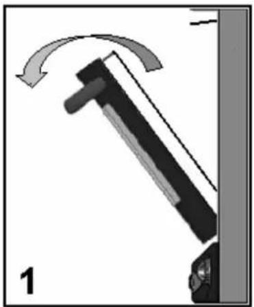
This appliance is fitted with our unique slide under door. As you open the door fully, it slides neatly under the oven. This feature maximises the space in the kitchen area by reducing the protruding door, giving easy access to the inside of the oven.
To open the door:-
- Pull the handle forward and down, as with any other drop down door
- When in fully open position push the door horizontally to slide the door in.
- Continue pushing until door stops in the parked position below the oven.
To close the door
- Grasp handle and slide door out from parked position.
- Continue until door fully extended.
- Rotate door upwards into the closed position.
OPEN


CLOSE


WARNING
- The grill area can get hot when the oven is in use, even if the grill is switched off.
- Care should be taken when removing pans from the grill, i.e. use of oven gloves, and by making use of the removal grill pan handle.
IMPORTANT
- The grill pan supplied is multi functional, for use in grill or oven.
- The handle design allows removal or insertion whilst the pan is in use.
• Always remove the handle when the pan is in use. - The grill MUST only be used with the door open.
Using the Grill
OFF

- Ensure gas cylinder/supply is connected and turned on. In the event of a gas smell turn off at gas cylinder/mains and contact supplier.
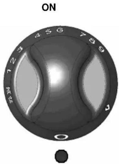
- To light: Open door and slide under, push in the control knob and turn clockwise to full rate. Hold a lighted match or taper to the burner and push the control knob in and hold. The burner should ignite and the control knob should be held in for 10 -15 seconds before release. If the burner goes out, repeat procedure, holding control knob for slightly longer.
- For models fitted with Spark Ignition the procedure is similar except that the burner can be ignited by depressing the ignition button, which is located on the fascia. Ignition must be carried out with the door open, and if the burner has not lit within 15 seconds the control knob should be released and the grill left for at least 1 minute before a further attempt to ignite the burner.
- On first use of the grill, it should be heated for about 20 minutes to eliminate any residual factory lubricants that might impart unpleasant smells to the food being cooked. A non-toxic smoke may occur when using for the first time so open any windows and turn on mechanical ventilators to help remove the smoke.
OPERATION
-
Although the grill does heat up quickly, it is recommended that a few minutes preheat be allowed.
-
Flame Failure Device (FFD): the grill burner is fitted with a flame sensing probe, which will automatically cut off the gas supply in the event of the flame going out. In the event of the burner flames being accidentally extinguished, turn off the burner control and do not attempt to re-ignite the burner for at least one minute.
-
It is normal for the flames on this burner to develop yellow tips as it heats up, particularly on Butane.
-
A reversible grill pan trivet enables the correct grilling height to be achieved. Grilling should be carried out on the middle shelf position.
Fast Toasting trivet in high position
Grilling Sausages trivet in high position
Grilling Steak/Bacon trivet in high position
Grilling Chops, etc trivet in low position
Slow Grilling trivet removed
-
To turn off: turn the control knob until the circle on the control knob is aligned with the dot on the control panel, this should be done by turning anti-clockwise. Always make sure the control knob is in the off position when you have finished grilling.
-
Note: the grill must only be used with the door open.
IMPORTANT
- The appliance is fitted with a fan cooling system. The cooling fan will automatically switch on after lighting the grill or oven burner.
- The fan will automatically switch off a few minutes after the burner is extinguished, when the front of the appliance has cooled sufficiently.
Using the Oven
OFF
ON (FULL)

O

O
- Ensure gas cylinder/supply is connected and turned on. In the event of a gas smell turn off at gas cylinder/mains and contact supplier.
- To light: Open door, push in the control knob and turn anti-clockwise to full rate (gas mark 9). Hold a lighted match or taper to the burner and push the control knob in and hold. The burner should ignite and the control knob should be held in for 10 -15 seconds before release. If the burner goes out, repeat procedure holding control knob for slightly longer.
- For models fitted with Spark Ignition the procedure is similar except that the burner can be ignited by depressing the ignition button, which is located on the fascia. Ignition must be carried out with the door open, and if the burner has not lit within 15 seconds the control knob should be released and the oven left for at least 1 minute before a further attempt to ignite the burner.
- Place the oven shelf in the required position and close the door. Set control knob to approximately gas mark 5 and heat the oven for about 30 minutes to eliminate any residual factory lubricants that might impart unpleasant smells to the meals being cooked. A non-toxic smoke may occur when using for the first time so open any windows and turn on mechanical ventilators to help remove the smoke.
-
Although the oven does heat up quickly, it is recommended that a 10 minutes preheat be allowed. The oven should be up to full temperature in about 15-20mins.
-
To turn off: turn the control knob clockwise until the circle on the control knob is aligned with the dot on the control panel.
- To remove a shelf, pull forward until it stops, raise at front and remove.
Oven Temperature Control
The temperature in the oven is controlled by a thermostatic gas tap and is variable over the range 130° C to 240° C. Approximate temperatures for the settings on the control knob are shown in the table below. The temperatures indicated refer to the centre of the oven and at any particular setting the oven will be hotter at the top and cooler towards the base. The variation between top and centre, and centre to bottom is approximately equivalent to one gas mark. Good use can be made of the temperature variation in several dishes requiring different temperatures may be cooked at the same time. In this way maximum benefit can be obtained from the gas used to heat the oven. Care should be taken not to overload the oven, adequate spacing being used to allow free circulation for heat.
Cooking Guidelines
Best results will be obtained by the shelf positions in this guide – please see chart on next page. It is not necessary to preheat the oven but advisable for a range of dishes. The oven is capable of full temperature in 15-20 minutes.
Most cookery books give details of the shelf positions and gas mark settings for each recipe. If in doubt about a recipe you intend to use, study the recipe carefully then find a similar dish in our guide and use our shelf position and gas mark setting recommendation. Shelf positions are from the top down. When roasting with aluminium foil care must be taken that the foil does not impair circulation or block the oven flue outlet.
Cooking Guidelines
| Gas Mark | Temperature | |||
| 1/4 - 1/2 | 265-275°F | 130-135°C | Very cool Meringues | |
| 1 285 | 140 Cool | Stewed fruit | ||
| 2 300 | 150 Cool | Rich fruit cake | ||
| 3 330 | 165 Warm | Baked custard | ||
| 4 355 | 180 Moderate | Victoria sandwich | ||
| 5 385 | 195 Fairly hot | Whisked sponges | ||
| 6 410 | 210 Hot | Short crust pastry | ||
| 7 430 | 220 Hot | Bread, scones | ||
| 8 445 | 230 Very hot | Puff pastry | ||
| 9 465 | 240 Very hot | Quick browning | ||
| Dish | Gas Mark | Shelf Position | Cooking Time |
| Scones | 7 2 | 8-15mins | |
| Small cakes | 5 2 | 15-25mins | |
| Victoria sandwich | 4 2 | 20-30mins | |
| Very rich fruit cake | 2 2 | Approx. 60mins per 500g | |
| Puff pastry | 8 2 | 15-30mins | |
| Flaky pastry | 7 2 | 15-30mins | |
| Shortcrust pastry | 6 2 | 15-55mins | |
| Shortbread fingers | 3 2 25 | 30mins | |
| Ginger nuts | 5 2 | 12-16mins | |
| Rice pudding | 2 3 | 100-120mins | |
| Baked custard | 3 3 | 50-60mins | |
| Fruit crumble | 5 3 | 30-40mins | |
| Beef | 3 | 3 | 25mins per 500g plus 25mins |
| 7 | 3 | 15mins per 500g plus 20mins | |
| Pork | 3 | 3 | 30mins per 500g plus 35mins |
| 7 | 3 | 25mins per 500g plus 25mins |
IMPORTANT
Always ensure food is properly cooked prior to serving.
Do's And Don'ts
DO read the user instructions carefully before using the appliance for the first time.
DO allow the oven to heat before using for the first time, in order to expelany smells before the introduction of food.
DO clean the appliance regularly.
DO remove spills as soon as they occur.
DO always use oven gloves when removing food shelves and trays from the oven.
DO check that controls are in the off position when finished.
DO NOT allow children near the cooker when in use. Turn pan handles away from the front so that they cannot be caught accidentally.
DO NOT allow fats or oils to build up in the oven trays or base.
DO NOT use abrasive cleaners or powders that will scratch the surfaces of the appliance.
DO NOT under any circumstances use the oven as a space heater.
DO NOT put heavy objects onto open grill and oven doors.
Leaks
If a smell of gas becomes apparent, the supply should be turned off at the cylinder IMMEDIATELY. Extinguish naked lights including cigarettes and pipes. Do not operate electrical switches. Open all doors and windows to disperse any gas escape. Butane/Propane gas is heavier than air; any escaping gas will therefore collect at a low level. The strong unpleasant smell of gas will enable the general area of the leak to be detected. Check that the gas is not escaping from an unlighted appliance. Never check for leaks with a naked flame, leak investigation should be carried out using a leak detector spray.
Regulations and Standards
In your own interest of safety, it is law that all gas appliances are installed and serviced by an authorized gas technician who will undertake work to safe and satisfactory standards. Failure to install the appliance correctly could invalidate any warranty or liability claims and lead to prosecution.
This appliance shall be installed in accordance with the local and National/European standards in force. Particular attention shall be given to the requirements regarding ventilation. Read the instructions before installing or using this appliance.
Ventilation
This appliance is suitable for installation into Holiday Homes, Touring Caravans and Boats. In all cases the national standards with regard to ventilation for the particular vehicle into which the appliance is to be installed must be adhered to.
The European Standard EN1949 - "Specification for the installation of LPG systems in leisure and other road vehicles", specifies that all appliances be installed in accordance with the manufacturer's instructions, including the adequate provision to avoid the accumulation of un-burnt gases. We recommend a vent in the floor (minimum=130mm 2 , maximum=3850mm 2 ) venting to the outside, to avoid the accumulation of un-burnt gases.
We also recommend that all ventilation holes in the appliance cabinet are baffled, to prevent direct draughts on the appliance.
Location of Appliance
This appliance may be installed in a kitchen/kitchen diner but NOT in a room containing a bath or a shower. LP gas appliances must not be fitted below ground level. e.g. in a basement.
IMPORTANT
- This appliance must be installed into an aperture, sealed off at either side in order to prevent draughts from adjoining cupboards/vents. Ensure that air vents and gas escape holes are kept clear, holes for cables and pipes must be sized to minimize air leakage between compartments.
- Under no circumstances should the ventilation hole exceed 3850mm 2 or other low level ventilation located in the compartment, including vents in kickboards. Low level vents in adjacent compartments are permitted.
- Cupboards beneath the appliance MUST be sealed to prevent a gas escape entering the living area.
WARNING
When installing DO NOT lift appliance using the door handles.
Position
The performance of this appliance meets the approval requirements of the European Standard for Domestic Cooking Appliances (EN30) which specifies a maximum allowable temperature rise of the furniture into which the appliance is installed of 65° C above the ambient temperature. To ensure compliance with the standard it is important the installation follows the minimum dimensions as shown in this manual.
All cooking appliances become hot during use, it is important the installer verifies the furniture construction material and that it is suitable for the application - i.e. plastic materials used in the construction may have a softening point lower than the maximum allowable temperature rise specified in the European Standard.
ALL combustible materials such as curtains and shelves must be kept well clear of the appliance, and their installation should meet all relevant local and national/European standards in force.
Fixing
Fixing screw positions are located as follows.
Screw into place using a flange head No 6 woodscrew
| Appliance Front Fixed Appliance | |
| S~OV72000 3 | front fixing holes each side of Oven opening |
| S~OG72000 3 | front fixing holes each side of Oven opening |
CONNECTION
Gas Connection
The gas connection is made to a 8mm ∅ inlet pipe beneath and to the front of the appliance depending on exact specification. Prior to connection remove the plastic protection plug from the fitting. It is recommended that the appliance be connected by copper pipe, rubber tubing MUST NOT be used.
The burners on this appliance have fixed aeration and no adjustment is necessary.
IMPORTANT
- This appliance is approved for use with LPG gas; Propane and Butane. We recommend using Propane gas for this appliance.
- Butane gas may be used, although the performance of the appliance maybe compromised when the ambient temperature is below 10°C .
- Butane gas should not be used when the ambient temperature is below 5°C .
• After installation the appliance must be tested for soundness - The gas supply input pressure to which this appliance is connected MUST not rise or fall by more than 2.5mbar (butane/propane) from nominal when ALL appliances connected to the supply are operated simultaneously. If this appliance is not installed in accordance with the instructions and tolerances detailed herein, we the manufacturer can not be held responsible for any problems that occur, or poor performance that is perceived/witnessed.
Connection - Electrical
Ensure that all electrical cables and wires are routed well clear of any heat source, including this appliance. Excess cord must be routed away from the appliance and must not come into contact with the oven or grill body.
The plugs must be accessible after installation to aid servicing.
IMPORTANT
• This appliance MUST be earthed
- A constant 12V supply is necessary at all times to ensure the cooling system operates correctly.
IMPORTANT
- Shut off gas supply at isolating valve, switch off electric supply and ensure all parts are cool before cleaning or servicing
- All servicing must be carried out by an approved competent person.
• After each service the appliance must be checked for gas soundness - This appliance must not be modified or adjusted unless authorized and carried out by the manufacturer or his representative. No parts other than those supplied by the manufacturer should be used on this appliance.
- If the supply cord is damaged, it must only be replaced by the manufacturer or his representative in order to avoid a hazard.
This appliance needs little maintenance other than cleaning. All parts should be cleaned using warm soapy water. Do not use abrasive cleaners, steel wool or cleansing powders. When cleaning the burner ring it is essential to ensure that the holes do not become blocked. The control knobs are a push fit and can be removed for cleaning.
1. Disconnect from gas supply
Open the oven door and remove the 3 screws from each side trim. Carefully slide the appliance out one third and disconnect the gas supply from the front left hand side of the appliance.
2. Remove appliance from housing
Check for any possible snagging of wires or pipes. If OK, lift appliance out onto a suitable surface.
3. Control replacement
Disconnect from gas supply (1). Remove appliance from housing (2).
Open the oven door and unscrew the 2 screws holding the thermostat probe in position and push the probe back out through the hole in the rear of oven. Remove the 4 retaining screws from the bottom of the appliance and to the rear of the control. This will remove the front curved fascia panel, this will allow access to the two retaining screws on the front trim. Disconnect the inlet pipe and two burner supply pipes. Remove the fittings off the old control and fit on the replacement.
4. Remove the grill burner
Disconnect from gas supply (1). Remove appliance from housing (2).
Open the oven door, and remove the top/sides insulation sheet. Drill the 4 pop rivets on top of the roof, then Lever off the 2 starlock washers retaining the grill burner.
5. Spark Ignition (where fitted)
Disconnect from gas supply (1). Remove appliance from housing (2).
Grill burner - Remove the screw from the bracket and spark ignition probe in the top of the burner. Trace the electrode wire back to the generator and pull off the connector.
Oven burner - Trace the electrode wire up the back of the cooker to the generator and pull off the connector. Unscrew the fixing screw on the spark electrode inside the oven cavity, then carefully pull the electrode from inside the oven and remove.
6. Grill burner injector (No62)
Disconnect from gas supply (1). Remove appliance from housing (2).
Release injector holder from bracket, disengage the grill pipe from the control and remove the injector.
7. Oven burner injector (No59)
Open the oven door and unscrew the burner retaining screw, slide the burner to the left and lift out. The injector is exposed to the right hand side of the cut out.
Unscrew the injector.
8. Thermocouple replacement
Disconnect from gas supply (1). Remove appliance from housing (2).
Grill burner - Remove the push on female terminal of the thermocouple from the right hand side thermal switch, located on the rear of front trim (viewed from front of appliance) Unscrew the nut at the burner.
Oven burner -. Remove the push on female terminal on the thermocouple from the right hand side thermal switch, located on the rear of front trim (viewed from front of appliance). Inside the oven cavity, the thermocouple is located above the burner on the rear wall. Unscrew the locknut and pull out the thermocouple from the rear of the appliance.
9. Removing Drop Down Oven Door
Open the door and engage 1 pin in each hinge (3.2 x 9.5mm pop rivets ideal). Lift the door and pull out of front trim.
10. Removing Thermal Switches
The thermal switches are used to activate the cooling fan system, and to stop the supply of gas in the event of fan failure. The switches are located between the oven roof and top trim, fixed to the rear of the front trim, one is positioned centrally and the other to the right (viewed from front of appliance).
Disconnect from gas supply (1). Remove appliance from housing (2). Open oven door and remove the 2 retaining screws from the heat deflection trim situated just below the appliance top trim, then remove. Disconnect all thermocouple wires from thermal switches and drill out the 4 pop rivets (2 on each thermal cut) to remove.
- USER AND INSTALLATION INSTRUCTIONS
- IMPORTANT
- CONSTRUCTION MATERIALS
- CONTENTS
- PROVISION OF VENTILATION
- POSITION
- WARNING
- OPERATION OF THE DOOR
- USING THE GRILL
- OPERATION
- USING THE OVEN
- OVEN TEMPERATURE CONTROL
- COOKING GUIDELINES
- DO'S AND DON'TS
- LEAKS
- REGULATIONS AND STANDARDS
- VENTILATION
- LOCATION OF APPLIANCE
- FIXING
- CONNECTION
- GAS CONNECTION
- CONNECTION - ELECTRICAL
- DISCONNECT FROM GAS SUPPLY
- REMOVE APPLIANCE FROM HOUSING
- CONTROL REPLACEMENT
- REMOVE THE GRILL BURNER
- SPARK IGNITION (WHERE FITTED)
- GRILL BURNER INJECTOR (NO62)
- OVEN BURNER INJECTOR (NO59)
- THERMOCOUPLE REPLACEMENT
- REMOVING DROP DOWN OVEN DOOR
- REMOVING THERMAL SWITCHES
Brand : THETFORD
Model : S-OV72000
Category : Cooker