
VMAX 850F - Mainframe EMC - Free user manual and instructions
Find the device manual for free VMAX 850F EMC in PDF.


| Product Type | Enterprise All-Flash Storage Array |
| Model | VMAX 850F |
| Manufacturer | DELL EMC |
| Maximum Raw Capacity | Up to 4 PBe (effective with compression) |
| Maximum Number of Drives | 1920 (2.5-inch SAS SSDs) |
| Maximum Cache | 16 TB (8 bricks x 2 TB per brick) |
| Maximum CPU Cores | 384 (dual Intel Ivy Bridge 12-core per director) |
| Maximum Front-End Ports | 192 (Fibre Channel, iSCSI, FICON) |
| RAID Levels | RAID 5 (7+1), RAID 6 (14+2) |
| Performance | Up to 4 million IOPS, <0.5 ms latency, 150 GB/s bandwidth |
| High Availability | 6 nines (99.9999%) availability, no single point of failure |
| Data Services | SRDF, TimeFinder SnapVX, eNAS, CloudArray, D@RE |
| Management | Embedded Unisphere for VMAX, Unisphere 360 |
| Operating System | HYPERMAX OS with real-time storage hypervisor |
| Cooling | Redundant hot-plug fans, front-to-rear airflow |
| Power Supply | Redundant hot-plug power supplies, N+1 |
| Form Factor | Modular brick architecture, floor tile footprint (1-4 tiles) |
| Dimensions per Floor Tile | Standard 19-inch rack cabinet, ~42U height (varies by configuration) |
| Weight per Bricks | Approximately 200-300 kg per brick (exact depends on configuration) |
| Power Consumption (Typical) | ~5-10 kW per brick (varies with load and SSDs) |
| Operating Temperature | 10°C to 35°C (50°F to 95°F) |
| Storage Temperature | -40°C to 70°C (-40°F to 158°F) |
| Humidity (Operating) | 20% to 80% non-condensing |
| Safety Certifications | FIPS 140-2 (D@RE), UL, CE, RoHS compliant |
| Repairability | Hot-swappable FRUs (drives, PSUs, fans, I/O modules) |
Frequently Asked Questions - VMAX 850F EMC
User questions about VMAX 850F EMC
0 question about this device. Answer the ones you know or ask your own.
Ask a new question about this device
Download the instructions for your Mainframe in PDF format for free! Find your manual VMAX 850F - EMC and take your electronic device back in hand. On this page are published all the documents necessary for the use of your device. VMAX 850F by EMC.
USER MANUAL VMAX 850F EMC
natural_image
Exterior view of a modern server tower with blue lighting and internal circuitry (no visible text or symbols)ABSTRACT
Recent engineering advancements with higher density, vertical, multi-layer cell flash technology have led to the development of higher capacity multi-terabyte flash drives. The introduction of these higher capacity flash drives has greatly accelerated the inflection point of where flash drives have the equivalent economics of traditional hard drives functioning as the primary storage media for enterprise applications in the data center. DELL EMC engineers foresaw this inflection point and are now pleased to introduce the VMAX® All Flash family. This white paper provides the reader with an in-depth overview of the VMAX All Flash family by providing details on the theory of operation, packaging, and the unique features which make it the premier all-flash storage product for the modern data center.
September 2016
The information in this publication is provided “as is.” EMC Corporation makes no representations or warranties of any kind with respect to the information in this publication, and specifically disclaims implied warranties of merchantability or fitness for a particular purpose.
Use, copying, and distribution of any EMC software described in this publication requires an applicable software license.
EMC ^2 , EMC, the EMC logo, are registered trademarks or trademarks of EMC Corporation in the United States and other countries. All other trademarks used herein are the property of their respective owners. © Copyright 2016 EMC Corporation. All rights reserved. Published in the USA. 09/16, white paper, Part Number H14920.1
EMC believes the information in this document is accurate as of its publication date. The information is subject to change without notice.
EMC is now part of the Dell group of companies.
TABLE OF CONTENTS
EXECUTIVE SUMMARY 5
INTENDED AUDIENCE....5
THE VMAX ALL FLASH FAMILY 5
Background....5
Introducing the VMAX All Flash Arrays .... 5
VMAX All Flash System Overview....6
A Modular Building Block Architecture 6
The Brick Overview....7
Brick Engines 8
Brick Engine CPU Core Configurations....8
Brick Engine Cache Configurations....8
Brick Drive Array Enclosures (DAEs) 9
VMAX 250F Model V-Brick DAEs....9
VMAX 450F and VMAX 850F Model Brick DAEs....9
Important notes about VMAX All Flash brick DAE capacity....11
FLASH OPTIMIZATION ON THE VMAX ALL FLASH 11
VMAX All Flash Cache Architecture and Caching Algorithms....11
Understanding Flash Cell Endurance....11
VMAX All Flash Write Amplification Reduction....12
Boosting Flash Performance with FlashBoost....12
HYPERMAX OS 12
VMAX ALL FLASH DATA SERVICES 12
Remote Replication with SRDF 13
Local Replication with TimeFinder SnapVX 13
Consolidation of Block and File Storage Using eNAS....13
Embedded Management (Embedded Unisphere for VMAX) 14
VMAX ALL FLASH – HIGH AVAILABILITY AND RESILIENCE 14
VMAX ALL FLASH CONFIGURATIONS FOR OPEN SYSTEMS....15
Open Systems V-Brick System Configurations for the VMAX 250F 15
Open Systems V-Brick System Configurations for the VMAX 450F and VMAX 850F....16
Open Systems V-Brick Front End Connectivity Options 16
Open System VMAX All Flash Software Packaging....18
VMAX ALL FLASH CONFIGURATIONS FOR MAINFRAME 19
Mainframe zBrick System Configurations for the VMAX 450F / 850F 19
Mainframe zBrick Front End Connectivity Options 20
VMAX All Flash for Mainframe Software Packaging 22
SUMMARY 23
REFERENCES......23
EXECUTIVE SUMMARY
In 2016, an inflection point has been reached where flash storage now has the equivalent density and economics of traditional spinning Hard Disk Drive (HDD) media. This inflection point has fundamentally changed the data storage landscape in the enterprise data center. To meet the demands of the all flash enterprise storage environment, DELL EMC is pleased to offer an all-flash offering called the VMAX All Flash family.
The VMAX All Flash family expands the conversation in the all-flash space to include mission-critical resiliency, native and trusted enterprise data services, and consolidation of workloads beyond block storage. VMAX All Flash sets itself apart from the other competitors in the enterprise flash storage space as it provides customers with:
• A trusted architecture delivering unmatched 6x9's availability for enterprise-level flash storage requirements
- The most trusted data services in the industry, including SRDF and Timefinder SnapVX - the gold standards for remote and local replication technologies
- Unmatched flash density per floor tile with both block and file workloads co-existing within the same system
VMAX All Flash offers unmatched simplicity for customers when it comes to planning, ordering, and management. There are three VMAX All Flash models: the VMAX 250F, the VMAX 450F, and the VMAX 850F. Customers can scale up and scale out using a simple modular architecture. Each VMAX All Flash model can be ordered with a pre-packaged software bundle – the entry "F" package, or the more encompassing "FX" package. Every VMAX All Flash model comes standard with embedded Unisphere for VMAX for easy and simple storage management and monitoring. VMAX All Flash also delivers unmatched simplicity for maintenance and licensing which helps dramatically lowers a customer's Total Cost of Ownership (TCO) of the product.
The VMAX All Flash family has truly changed the landscape of the enterprise data center. The primary components and benefits of this game changing product will be discussed in detail in the following sections of this document.
INTENDED AUDIENCE
This white paper is intended for DELL EMC customers and potential customers, DELL EMC Sales and Support Staff, Partners, and anyone interested in gaining a better understanding of the VMAX All Flash storage array and its features.
The VMAX All Flash Family
Background
Enterprise storage capacity and storage performance requirements have increased dramatically in recent years with the need to support millions of virtual devices and virtual machines. Although traditional spinning disk media can still meet the storage capacity requirements, it is having difficulty meeting the performance requirements (now measured in the millions of IOPS) for these environments.
Until recently, the industry was in a quandary as the economics of all flash storage were still prohibitive; however, the recent advancements in flash technology – specifically the development vertical, 3-bit, charge trap NAND architectures - have led to a breakthrough in the capacity and economics of flash storage. This breakthrough has greatly accelerated the inflection point of where flash storage has the same economics of traditional spinning disk media. The release of these new drives is now allowing the enterprise data center to meet the storage capacity and performance requirements for highly virtualized environments at affordable economics.
Introducing the VMAX All Flash Arrays
To meet the emerging requirements of the enterprise storage environment, DELL EMC is pleased to introduce a new all flash offering called VMAX All Flash. The VMAX All Flash will offer three distinct base models- the VMAX 250F, the VMAX 450F, and the VMAX 850F. The VMAX All Flash arrays have at their foundation the trusted Dynamic Virtual Matrix architecture and HYPERMAX OS; however, they differ from the VMAX hybrid arrays as they are true all flash arrays – being the VMAX products specifically targeted to meet the storage capacity and performance requirements of the all flash enterprise data center. The VMAX All Flash products are feature-rich all flash offerings with specific capabilities designed to take advantage of the new higher capacity flash drives used in the densest configuration possible. The VMAX All Flash arrays offer enterprise customers the trusted VMAX data services, the improved simplicity, capacity, and performance which their highly virtualized environments demand, while still meeting the economics of the more traditional storage workloads.
The VMAX All Flash product line has been engineered to deliver on the following key design objectives:
- Performance – Regardless of workload and regardless of storage capacity utilization, VMAX All Flash is designed to provide consistently predictable high performance to the enterprise data center, delivering up to 4 million IOPS with less than 0.5 ms latency at 150 GB/sec bandwidth.
- High Availability and Resiliency – VMAX All Flash is built with trusted architecture which bears no single points of failure and has a proven 6x9's availability track record. The ability to use of SRDF gives customers full multi-site replication options for disaster recovery and rapid restart.
- Inline Compression - Compression is a space saving function designed to allow the HYPERMAX OS to manage capacity in the most efficient way possible. Compression is performed by the HYPERMAX OS within the system using multiple compression ranges in order to achieve the 2:1 average for the system.
- Non-Disruptive Migration (NDM) - NDM is designed to help automate the process of migrating hosts and applications to a new VMAX All Flash array with no downtime at all.
- Enhancing Flash Drive Endurance – VMAX All Flash has unique capabilities to greatly minimize write amplification on the flash drives. It employs large amounts of cache to store writes and then uses intelligent de-stage algorithms to coalesce the writes into a larger sequential write – minimizing random write I/O to the back end. VMAX All Flash also employs proven write folding algorithms which drastically reduce the amount of write I/O to the back end.
- Flash Density – Using high capacity flash drives, VMAX All Flash will deliver the highest IOPS/TB/floor tile in the industry. VMAX All Flash support for high capacity flash drives provides a differentiated capability versus many all flash alternatives. It allows the system to leverage the increases in flash drive densities, economies of scale, and fast time to market provided by the suppliers for industry standard flash drive technology.
- Scalability – VMAX All Flash configurations are built with modular building blocks called "Bricks". A Brick includes an engine and two drive DAEs pre-configured with an initial total usable capacity. Brick capacity can be scaled up in specific increments of usable capacity called Flash Capacity Packs.
- Data Services – Full support for the industry's gold standards in remote replication with SRDF and local replication with Timefinder SnapVX. VMAX All Flash will also have a full integration with DELL EMC AppSync for easier local replication management of critical applications.
- Consolidation – The VMAX All Flash are the only all flash storage products in the industry which can consolidate open system block and file storage onto a single floor tile. VMAX All Flash supports many front end connectivity options including Fibre Channel, iSCSI, and FICON for Mainframe
- Streamlined Packaging - The VMAX All Flash family450F850Fwill feature an "F" and "FX" options.. The difference in the models is specifically related to the greatly simplified software packaging for the VMAX All Flash product line. The VMAX All Flash base models will always be referred to as the VMAX 250F, 450F, and 850F. The base "F" model will offer an entry level software packaging which will include features such as embedded Unisphere; while the "FX" includes the entry level "F" packaging, plus more advanced software offerings such as SRDF.
- Ease of Management – Embedded Unisphere for VMAX is provided in both the F and FX package. The Unisphere for VMAX intuitive management interface allows IT managers to maximize productivity by dramatically reducing the time required to provision, manage, and monitor VMAX All Flash storage assets. The fact that Unisphere for VMAX is embedded within VMAX All Flash allows for this simplicity of management without the need for additional servers and hardware. The FX package also includes Unisphere 360, which provides storage administrators the ability to view site-level health reports for every VMAX in the data center, and also coordinate compliance to code levels and other infrastructure maintenance requirement
VMAX All Flash System Overview
VMAX All Flash is architected to support the densest flash configuration possible. VMAX All Flash support for high capacity flash drives provides a differentiated capability versus many all flash alternatives. It allows VMAX All Flash to leverage the increases in flash drive densities, economies of scale, and faster time to market provided by the suppliers for industry standard flash drive technology.
The shift to higher capacity flash drives provides an attractive alternative to hybrid arrays in terms of acquisition cost and overall total cost of ownership. Other VMAX All Flash advantages such as higher performance, predictable latency, increased density, reduced power and cooling, and reduced drive replacement will accelerate deployment of all flash based VMAX storage systems going forward.
A Modular Building Block Architecture
VMAX All Flash employs a simplified appliance based software packaging and modular building block configuration to reduce complexity to make it easier to configure and deploy. This architecture allows it to scale to deliver predictable high performance where needed. These building blocks are called "bricks".
There are two types of bricks available for the VMAX All Flash:
- The V-Brick which supports open system configurations with Fibre Channel and / or iSCSI connectivity and FBA device formatting
• The zBrick which supports Mainframe configurations with FICON connectivity and CKD device formatting.
Note: In this document, the term "brick" will be used when discussing features and functions applicable to both the V-Brick and the zBrick. The zBrick will be discussed in more detail in the VMAX All Flash Mainframe support portion of this document.
The Brick Overview
The core element of VMAX All Flash is the brick. Each brick has the following components:
• One engine using the dynamic virtual matrix architecture running HYPERMAX OS
• Fully redundant hardware with multiple power supplies and interconnecting fabrics
- No single points of failure architecture
- Proven 6x9s availability
• 2 x 2.5" drive slot Drive Array Enclosures (DAEs)
- VMAX 250F has 2 x 25 slot 2.5" drive, VMAX 450F / 850F has 2 x 120 slot 2.5" drive
o VMAX All Flash starter brick configuration has a set amount of usable capacity
○ Additional V-Brick storage capacity is added in defined increments called "Flash Capacity Packs", while additional zBrick storage capacity is added in defined increments called "zCapacity Packs".
• Up to 32 ports of front end connectivity
- Up to 2 TB of Cache per Brick
The following table details the various VMAX All Flash model brick specifications:
Table 1. Brick Specifications by VMAX All Flash Model
| Component | Specification | VMAX 250F | VMAX 450F | VMAX 850F |
| System Layout | Floor Tile Space Required | 1 | 1 - 2 | 1 - 4 |
| Compute | # of Bricks per System | 1 - 2 | 1 - 4 | 1 - 8 |
| Support for Mainframe zBrick | No | Yes | Yes | |
| Maximum # of cores per system | 96 | 128 | 384 | |
| Cache | Cache per Brick Options | 512 GB, 1 TB, and 2 TB | 1 TB and 2 TB | |
| Mixed cache support | Yes | No | No | |
| Ports and Modules | Maximum FE modules per V-Brick | 8 (32 total FE ports per V-Brick) | 6 (24 total FE ports per V-Brick) | |
| Maximum FE modules per zBrick | NA | 6 (24 total FICON ports per zBrick) (1) | ||
| Maximum FE ports per system | 64 | 96 | 192 | |
| Drives and Capacity | Brick DAE Type and QTY | 2 x 25 slot, 2.5" (DAE25) | 2 x 120 slot, 2.5" | |
| Maximum # of drives per system | 100 | 960 | 1920 | |
| Maximum open systems effective capacity per system (1) | 1 PBe | 2 PBe | 4 PBe | |
| Maximum mainframe usable capacity per system (2) | NA | 800 TBu | 1.7PBu | |
| Starter Brick usable capacity | 11 TBu | 53 TBu | ||
| Flash Capacity Pack increment size | 11 TBu | 13 TBu | ||
| RAID Options | RAID 5 (3+1), RAID 6 (6+2) | RAID 5 (7+1), RAID 6 (14+2) | ||
| Supported V-Brick Flash Drive Sizes | 960 GB, 1.92 TB, 3.84 TB, 7.68 TB, 15.36 TB | 960 GB, 1.92 TB, 3.84 TB | ||
| Supported zBrick Flash Drives Sizes | NA | 960 GB, 1.92 TB, 3.84 TB | ||
(1) Default zBrick comes with 2 FICON modules. Extra FICON modules can be ordered at la carte
(2) DELL EMC uses PBu (and TBu) to define usable storage capacity in the absence of compression, i.e. referring to the amount of physical storage in the box. DELL EMC uses PBe (and TBe) to define effective storage capacity in the presence of compression,
(a) i.e. if a customer has 50TBu of physical storage, and it is compressible on a 2:1 basis, then the customer has 100TBe (Effective storage).
The brick concept allows VMAX All Flash to "scale up" and "scale out". Customers can scale up by adding Flash Capacity Packs. Each Flash Capacity Pack has a multiple of 13 TBu of usable storage for the VMAX 450F / VMAX 850F models, and 11 TBu for the VMAX 250F model. VMAX All Flash scales out by aggregating up to two bricks for the VMAX 250F, and up to eight bricks for the VMAX 450F / 850F in a single system with fully shared connectivity, processing, and capacity resources. Scaling out a VMAX All Flash system by adding additional bricks produces a predictable, linear performance improvement regardless of the workload.
Brick Engines
The brick engine is the central I/O processing unit, redundantly built for high availability. It consists of redundant directors that each contain multi-core CPUs, memory modules, and attach interfaces to universal I/O modules, such as front-end, back-end, InfiniBand, and flash I/O modules.
The foundation of the brick engine is the trusted Dynamic Virtual Matrix Architecture. Fundamentally, the virtual matrix enables inter-director communications over redundant internal InfiniBand fabrics. The InfiniBand fabric provides a foundation for a highly scalable, extremely low latency, and high bandwidth backbone which is essential for an all flash array. This capability is also essential for allowing the brick concept to scale upwards and scale outwards in the manner that it does.
Brick Engine CPU Core Configurations
Each brick engine has two directors, with each director having dual CPU sockets which can support multi-core, multi-threaded Intel processors. The following table details the engine CPU core layout for each VMAX All Flash model:
Table 2. Brick Engine CPU Cores per VMAX All Flash Model
| VMAX All Flash Model | Engine CPU Type | Cores per Director | Cores per Brick | Max Cores per System |
| 250F (V-Brick Only) | Dual Intel Broadwell 12 core | 24 | 48 | 96 (2 bricks max.) |
| 450F | Dual Intel Ivy Bridge 8 core | 16 | 32 | 128 (4 bricks max.) |
| 850F | Dual Intel Ivy Bridge 12 core | 24 | 48 | 384 (8 bricks max.) |
The brick engine uses a core pooling mechanism which can dynamically load balance the cores by distributing them to the front end, back end, and data services (such as SRDF, eNAS, and embedded management) running on the engine. The core pools can be dynamically tuned to shift the bias of the pools at any time to front end heavy or back end heavy workloads to further optimize the solution for a specific use case.
Aside from being able to dynamically adjust the core pools, VMAX All Flash has the capability to implement advanced Quality of Services (QoS), such as setting the maximum amount of IOPS for a particular storage group. This is extremely helpful at properly managing system core consumption so that a “noisy” virtual machine or host cannot overly consume system resources. QoS helps ensure that all connected hosts and virtual machines receive an evenly distributed amount of resources to deliver the maximum performance possible in terms of IOPS and throughput.
Brick Engine Cache Configurations
Every brick director has 16 memory slots which can be populated with 32 GB and 64 GB DDR4 DIMMS to achieve up to 1 TB cache per director (2 TB cache maximum per brick engine).
Table 3. Brick Engine Cache Configuration per VMAX All Flash Model
| VMAX All Flash Model | Cache per Brick | Max Cache per System |
| 250F (V- Brick Only) | 512 GB, 1 TB, 2 TB | 4 TB (2 bricks max.) |
| 450F | 1 TB or 2 TB | 8 TB (4 bricks max.) |
| 850F | 1 TB or 2 TB | 16 TB (8 bricks max.) |
For dual brick VMAX All Flash 250F models, the system can use engines with differing cache sizes (mixed memory). For example, the cache for the engine on brick A can be 1 TB while the cache for the engine for brick B can be 512 TB. This would yield a total system cache size of 1.5 TB. The difference in cache sizes between the engines has to be one capacity size smaller or larger. Valid mixed memory configurations for the VMAX 250F are shown in the following table:
Table 4. VMAX 250F Mixed Engine Cache Size Configurations
| Mixed Memory Configuration | Smallest Engine Cache Size | Largest Engine Cache Size | Total System Cache |
| Configuration 1 | 512 GB | 1 TB | 1.5 TB |
| Configuration 2 | 1 TB | 2 TB | 3 TB |
Note: The VMAX 450F and 850F models do not support mixed cache sizes between engines. In these systems, the cache size between engines must be equal.
The VMAX All Flash family supports Dynamic Cache Partitioning (DCP) on the system engines. DCP is a QoS feature which allows for the fencing off of specific amounts of cache for particular environments such as “production” from “development”. Another example would be the separation of cache resources for “file data” from “block data” on systems which are using eNAS services. Being able to fence off and isolate cache resources is key enabler for multi-tenant environments.
Brick Drive Array Enclosures (DAEs)
VMAX 250F Model V-Brick DAEs
Each brick for the VMAX 250F comes with two 25 slot, 2.5" drive, 2U front loading DAEs along with 11 TBu of pre-configured initial capacity that can use either RAID 5 3+1 or RAID 6 6+2 protection. The VMAX 250F DAE supports 12 Gb/sec SAS connectivity and requires 12 Gb/sec SAS flash drives. Flash drives which use 6 Gb/sec SAS connectivity are not supported in the VMAX 250F. The VMAX 250F DAE has dual ported drive slots and dual power zones for high availability.
Figure 1. Fully populated VMAX 250F V-Brick DAE

natural_image
Front view of a multi-chamber industrial control unit with multiple drive bays and cooling units (no visible text or labels)Additional scale up capacity is added to the VMAX 250F system using flash capacity pack increments of 11 TBu, scaling up to a maximum of effective capacity of 500 TBe per brick. A dual brick VMAX 250F can scale up to a total capacity 1PBe using a half rack (20U) within a single floor tile footprint.
VMAX 450F and VMAX 850F Model Brick DAEs
Each brick for the VMAX 450F and VMAX 850F comes with two 120 slot, 2.5" drive, 3U drawer DAEs, along with 53 TBu of pre-configured initial capacity that can use either RAID 5 7+1 or RAID 6 14+2 protection. Each VMAX 450F and VMAX 850F brick DAE uses dual ported drive slots and uses four separate power zones to eliminate any single points of failure. The VMAX 450F and VMAX 850F brick DAE layout is shown in the diagram below:
Figure 2. VMAX 450F / 850F Brick DAE Layout – Drive Slots and Power Zones

flowchart
graph TD
    subgraph_Row_A["Row A"]
        A1["0 1 2 3 4"] --> PSU_A1["PSU A1"]
        A2["0 1 2 3 4"] --> PSU_A2["PSU A2"]
        A3["0 1 2 3 4"] --> PSU_B1["PSU B1"]
        A4["0 1 2 3 4"] --> PSU_B2["PSU B2"]
    end

    subgraph_Row_B["Row B"]
        B1["0 1 2 3 4"] --> PSU_A1
        B2["0 1 2 3 4"] --> PSU_A2
        B3["0 1 2 3 4"] --> PSU_B1
        B4["0 1 2 3 4"] --> PSU_B2
    end

    subgraph_Row_C["Row C"]
        C1["0 1 2 3 4"] --> PSU_A1
        C2["0 1 2 3 4"] --> PSU_A2
        C3["0 1 2 3 4"] --> PSU_B1
        C4["0 1 2 3 4"] --> PSU_B2
    end

    subgraph_Row_D["Row D"]
        D1["0 1 2 3 4"] --> PSU_A1
        D2["0 1 2 3 4"] --> PSU_A2
        D3["0 1 2 3 4"] --> PSU_B1
        D4["0 1 2 3 4"] --> PSU_B2
    end

    subgraph_Row_F["Row F"]
        F1["0 1 2 3 4"] --> PSU_A1
        F2["5 6 7 8 9"] --> PSU_A2
        F3["1 1 1 2 3 4"] --> PSU_B1
        F4["1 5 6 7 8 9"] --> PSU_B2
    end

    subgraph_Row_G["Row G"]
        G1["0 1 2 3 4"] --> PSU_A1
        G2["1 1 1 2 3 4"] --> PSU_A2
        G3["1.5 6 7 8 9"] --> PSU_B1
        G4["1.5 6 7 8 9"] --> PSU_B2
    end

    subgraph_Row_H["Row H"]
        H1["0 1 2 3 4"] --> PSU_A1
        H2["1.5 6 7 8 9"] --> PSU_A2
        H3["1.5 6 7 8 9"] --> PSU_B1
        H4["1.5 6 7 8 9"] --> PSU_B2
    end
Additional scale up capacity is added to the system in multiples of 13 TBu increments called "Flash Capacity Packs" for V-Bricks and "zCapacity Packs" for zBricks. The capacity pack concept allows for considerable internal capacity growth over the lifespan of the VMAX 450F and VMAX 850F arrays – especially when higher capacity flash drives are used. Each VMAX 450F and VMAX 850F system can start small with as little as 53 TBu of capacity then scale to up to 500 TBu of usable capacity using a single 2 TB cache engine. The additional capacity can be added into the empty slots of the DAEs. This allows for easy expansion as no extra DAEs would need to be added into the system bay. When a two brick VMAX 450F or VMAX 850F system bay is deployed with 2 TB cache engines using (2:1) compression, a customer can have up to 1 PBe of effective flash capacity on a single floor tile while using only 500 TB of physical storage. Using an average of 2:1 compression, the VMAX 450F system can scale to 2 PBe and the VMAX 850F system can scale to 4 PBe.
Figure 3. Fully populated VMAX 450F / 850F Brick DAE

natural_image
Close-up of an electric vehicle battery pack with orange grid panels and cooling fins (no visible text or symbols)Important notes about VMAX All Flash brick DAE capacity
- VMAX All Flash arrays will use a single RAID protection scheme for the entire system. The specific protection scheme is determined by the initial usable capacity of the system. All follow on capacity and brick additions will use the same RAID protection scheme as the initial usable capacity (53 TBu for the VMAX 450F and VMAX 850F, 11 TBu for the VMAX 250F) regardless of the drive size used by the additional flash capacity pack.
- VMAX All Flash addressable capacity, space available for host IO, is governed by the amount of total cache in the system. Typically, 1 TB of V-Brick engine cache can usually support up to 250 TB of open system host addressable storage; while 1 TB of zBrick engine cache can usually support up to 100 TB of mainframe host addressable storage. This becomes important in properly sizing a VMAX All Flash system with compression. As an example, if a customer requires having 1 PBe of addressable storage compressed at a 2:1 ratio, this means that the system will require 4 TB of system cache and 500 TB of physical storage.
• Multiple flash drive sizes can co-exist within the brick DAE for the VMAX 250F, VMAX 450F, and VMAX 850F.
• The brick RAID groups span across both DAEs - The VMAX All Flash will offer the "Diamond" Service Level for internal storage and the "Optimized" Service Level for external disk storage such as Cloud Array.
- Spare drive requirements are calculated with 1 spare per 50 drives of a particular type, on a per engine basis
• Mainframe zBrick DAEs will support 960 GB, 1.92 TB and 3.84 TB flash drives
FLASH OPTIMIZATION ON THE VMAX ALL FLASH
All flash based storage systems demand the highest levels of performance and resiliency from the enterprise storage platforms that support them. The foundation of a true all flash array is an architecture which can fully leverage the aggregated performance of modern high density flash drives while maximizing their useful life. VMAX All Flash has several features built into the architecture of the product specifically designed to maximize flash drive performance and longevity. This section will discuss these features in detail.
VMAX All Flash Cache Architecture and Caching Algorithms
The VMAX family is built upon a very large, high-speed DRAM cache based architecture, driven by highly complex and optimized algorithms. These algorithms accelerate data access by avoiding physical access to the back end whenever possible.
DELL EMC has spent many years developing and optimizing caching algorithms. The VMAX cache algorithms optimize reads and writes to maximize I/Os serviced from cache and minimize access to back end flash drives. The system also goes to lengths at trying to predict what data may be needed in the future by the applications by an IO's locality of reference. This data is also pulled up into cache.
Some of the techniques used by the cache algorithms to minimize disk access are:
• 100% of host writes are cached
• More than 50% of reads are cached
- Recent data is held in cache for long periods, as that is the data most likely to be requested again
- Intelligent algorithms de-stage in a sequential manner
Understanding Flash Cell Endurance
Write cache management is essential to improving performance but it is also the key part of how VMAX All Flash helps extend the endurance of flash drives. Flash drive longevity and endurance are most impacted by writes, particularly small block random writes. Writing to a flash cell requires that the cell be first erased of any old data and then be programmed with the new data. This process is called the Program and Erase Cycle (P/E Cycle). Each flash cell has a finite number of P/E Cycles that it can endure before it wears out (can no longer hold data). Most modern flash cells can endure several thousand P/E Cycles.
One of the peculiarities of flash is that writes are spread out across a flash page (typically KBs in size); however, prior to the write operation, the existing data in entire flash block (typically MBs in size) that the page is located in must be erased. Prior to erasing the page, the flash controller chip finds an empty (erased) location on the drive and copies (writes) any existing data from the page to that location. Because of how flash writes data, a simple 4 KB write from a host could result in many times that amount of data being written internally on the drive causing P/E cycling on a large number of cells. This write multiplying effect is called "Write Amplification" and is detrimental to flash cell endurance. This effect is even more dramatic with small block random write workloads. In this situation, a large number of small block random writes tends to "buckshot" across the drive, impacting an even greater number of cells and invoking P/E cycling on a much larger cell area. Write amplification is not nearly as significant with larger sequential writes as this data is written sequentially local to a single flash block, thereby aligning better with flash page sizes and containing the P/E cycling to a smaller area.
VMAX All Flash Write Amplification Reduction
Write Amplification must be properly controlled and mitigated in order to ensure the longevity of flash devices as uncontrolled write amplification is the number one reason for premature wear out of flash storage. Controlling flash cell write amplification is one of the VMAX All Flash's greatest strengths and is what sets it truly apart from other competitor flash arrays. Aside from intelligent caching algorithms which keep data in cache as long as possible, the VMAX All Flash employs to additional methods to minimize the amount of writes to flash. These methods are:
- Write Folding – Write Folding avoids unnecessary disk IOs when hosts re-write to a particular address range. This re-written data is simply replaced in cache and never written to the flash drive. Write folding can reduce writes to the flash drives by up to 50%.
- Write Coalescing – Write Coalescing merges subsequent small random writes from different times into one large sequential write. These larger writes to the flash drives align much better with the page sizes within the flash drive itself. Using write coalescing, VMAX All Flash can take a highly random write host IO workload and make it appear as a sequential write workload to the flash drives.
- Timefinder SnapVX Nocopy Linked Target Functionality – Timefinder SnapVX provides very low impact (space efficient) point in time snapshots for source volumes. Typically when a user wishes to unlink a target volume from a snapshot, as often done in setting up a development environment, the unlinking operation would require a full volume copy of the source volume to the target in order for the target to be used after being unlinked. This would also result in a large increase in back end capacity usage with large amount of write operations on the back end drives. SnapVX eliminates this requirement as the point in time image is still accessible after unlinking the nocopy target volume. This saves the back end flash devices from enduring a large amount of write activity.
- Advanced Wear Analytics - VMAX All Flash also includes advanced drive wear analytics optimized for high capacity flash drives to make sure writes are distributed across the entire flash pool to balance the load and avoid excessive writes and wear to particular drives. Not only does this help manage the flash drives in the storage pools, it makes it easy to add and rebalance additional storage into the system.
All of the write amplification reduction techniques used by VMAX All Flash result in a significant reduction in writes to the back end, which in turn significantly increases the longevity of the flash drives used in the array.
Boosting Flash Performance with FlashBoost
DELL EMC is always looking to improve performance in its products. With every new hardware platform and release of software, the company makes strong efforts to remove potential bottlenecks which can impede performance in any way. One feature that DELL EMC introduced and has made standard as a part of HYPERMAX OS is "FlashBoost". FlashBoost maximizes HYPERMAX OS efficiency by servicing read requests directly from the back-end flash drives. This approach eliminates steps required for processing IO through global cache and reduces the latency for reads, particularly for flash drives. Customers with heavy read miss workloads residing on flash can see up to 100% greater IOPS performance.
HYPERMAX OS
The VMAX All Flash engines leverage the trusted and proven HYPERMAX OS. It combines proven industry-leading high availability, I/O management, quality of service, data integrity validation, data movement, and data security with an open application platform. HYPERMAX OS features the first real-time, non-disruptive storage hypervisor that manages and protects embedded services by extending high availability to services that traditionally would have run external to the array. The primary functions of HYPERMAX OS are to manage the core operations performed on the array such as:
- Processing IO from hosts
- Implementing RAID protection
• Optimizing performance by allowing direct access to hardware resources
• System Management and Monitoring - Implementing data services including local and remote replication
VMAX ALL FLASH DATA SERVICES
The VMAX All Flash product line comes complete with best in class data services. In VMAX, data services are processes which help protect, manage, and move customer data on the array. These services run natively, embedded inside the VMAX itself using the HYPERMAX OS hypervisor to provide a resource abstraction layer. This allows the data services to share pooled resources (CPU cores, cache, and bandwidth) within the array itself. Doing this optimizes performance across the entire system and also reduces complexity in the environment as resources (system cache, CPU cores, and outside appliances) do not need to be dedicated.
Some of the most sought after data services that will be offered by the VMAX All Flash product line are:
- Remote Replication with SRDF
• Local Replication with TimeFinder SnapVX - Embedded NAS (eNAS)
Remote Replication with SRDF
SRDF is perhaps the most popular data service in the enterprise data center as it is considered a gold standard for remote replication. Up to 70% of fortune 500 companies running VMAX use this tool to replicate their critical data to geographically dispersed data centers throughout the world. SRDF offers customers the ability replicate tens of thousands of volumes to a maximum of four different locations globally.
VMAX All Flash runs an enhanced version of SRDF specific for all flash use cases. This version uses multi-core, multi-threading techniques to boost performance; and powerful write folding algorithms to greatly reduce replication bandwidth requirements along withsource and target array back end writes to flash.
There are three primary flavors of SRDF that a customer can choose from:
(1) SRDF Synchronous (SRDF/S) – SRDF/S delivers zero data loss remote mirroring between data centers separated by up to 60 miles (100 km).
(2) SRDF Asynchronous (SRDF/A) – SRDF/A delivers asynchronous remote data replication between data centers up to 8000 miles (12875 km) apart. SRDF/A can be used to support three or four site topologies as required by the world's most mission critical applications.
(3) SRDF/Metro – SRDF/Metro delivers active-active high availability for non-stop data access and work load mobility within a data center, or between data centers separated by up to 60 miles. SRDF/Metro allows for storage array clustering, enabling even more resiliency, agility, and data mobility. SRDF/Metro allows hosts or host clusters access to LUNs replicated between two different sites. The hosts can see both views of the Metro Replicated LUN (R1 and R2), but it appears to the host OS as if it were the same LUN. The host can then write to both the R1 and R2 devices simultaneously. This use case accounts for automated recovery and the seamless failover of applications thus avoiding recovery scenarios all together. Other key features of SRDF Metro are:
- It provides concurrent access of LUNS /storage groups for non-stop data access and higher availability across metro distances
• It delivers simpler and seamless data mobility
• It supports stretch clustering which is ideal for Microsoft and VMware environments
SRDF software is included in the VMAX All Flash FX software package, with no capacity based licensing. It can be ordered a la carte as an addition to the F software package. Any hardware needed to support SRDF must be purchased separately.
Local Replication with TimeFinder SnapVX
Every VMAX All Flash array comes standard with the local replication data service Timefinder SnapVX as it is included as part of the F package. SnapVX provides very low impact snapshots and clones for VMAX LUNs. SnapVX supports up to 256 snapshots per source volume and up to 16 million snap shots per array. Users can assign names to identify their snapshots, and they have the option of setting automatic expiration dates on each snapshot.
SnapVX provides the ability to manage consistent point-in-time copies for storage groups with a single operation. Up to 1024 target volumes can be linked per source volume, providing read/write access as pointers or full-copy clones.
Local replication with SnapVX starts out as efficient as possible by creating a snapshot, a pointer based structure that preserves a point in time view of a source volume. Snapshots do not require target volumes, share back-end allocations with the source volume and other snapshots of the source volume, and only consume additional space when the source volume is changed. A single source volume can have up to 256 snapshots.
Each snapshot is assigned a user-defined name and can optionally be assigned an expiration date, both of which can be modified later. New management interfaces provide the user with the ability to take a snapshot of an entire Storage Group with a single command.
A point-in-time snapshot can be accessed by linking it to a host accessible volume referred to as a target. The target volumes are standard thin LUNs. Up to 1024 target volumes can be linked to the snapshot(s) of a single source volume. This limit can be achieved either by linking all 1024 target volumes to the same snapshot from the source volume, or by linking multiple target volumes to multiple snapshots from the same source volume. However, a target volume may only be linked to a single snapshot at a time.
By default, targets are linked in a no-copy mode. This no-copy linked target functionality greatly reduces the amount of writes to the back end flash drives as this eliminates the requirement of performing a full volume copy of the source volume during the unlink operation in order to use the target volume for host IO. This saves the back end flash devices from enduring a large amount of write activity during the unlink operation, further reducing potential write amplification on the VMAX All Flash array.
Consolidation of Block and File Storage Using eNAS
The Embedded NAS (eNAS) data service extends the value of VMAX All Flash to file storage by enabling customers to leverage vital enterprise features including flash level performance for both block and file storage, as well as simplify management, and reduce deployment costs by up to 33%. VMAX All Flash with the eNAS data service becomes a unified block and file platform, using a multi-controller, transaction NAS solution designed for customers requiring hyper consolidation for block storage (the traditional VMAX use case) combined with moderate capacity, high performance file storage in mission-critical environments. Common eNAS use cases
include running Oracle® on NFS, VMware® on NFS, Microsoft® SQL on SMB 3.0, home directories, and Windows server consolidation.
Embedded NAS (eNAS) uses the hypervisor provided in HYPERMAX OS to create and run a set of virtual machines within the VMAX All Flash array. These virtual machines host two major elements of eNAS: software data movers and control stations. The embedded data movers and control stations have access to shared system resource pools so that they can evenly consume VMAX All Flash resources for both performance and capacity.
Aside from performance and consolidation, some of the benefits that VMAX All Flash with eNAS can provide to a customer are:
- Scalability – easily serve over 6000 active SMB connections
• Meta-data logging file system ideally suited for an all flash environment
• Built-in asynchronous file level remote replication with File Replicator
• Integration with SRDF/S
- Small attack surface – not vulnerable to viruses targeted at general purpose operating systems
The eNAS data service is included in the FX software package. It can be ordered a la carte as an additional item with the F software package. All hardware required to support eNAS on the VMAX All Flash must be purchased separately
Embedded Management (Embedded Unisphere for VMAX)
VMAX All Flash customers can take advantage of simplified array management using embedded Unisphere for VMAX. Unisphere for VMAX is an intuitive management interface that allows IT managers to maximize human productivity by dramatically reducing the time required to provision, manage, and monitor VMAX All Flash storage assets.
Embedded Unisphere enables customers to simplify management, reduce cost, and increase availability by running VMAX All Flash management software directly on the array. Embedded management is configured in the factory to ensure minimal setup time on site. The feature runs as a container within the HYPERMAX OS hypervisor, eliminating the need for a customer to allocate their own equipment to manage their arrays. Aside from Unisphere, other key elements of the eManagement data service include Solutions Enabler, Database Storage Analyzer, and SMI-S management software.
Unisphere for VMAX delivers the simplification, flexibility, and automation that are key requirements to accelerate the transformation to the all flash data center. For customers who frequently build up and tear down storage configurations, Unisphere for VMAX makes reconfiguring the array even easier by reducing the number of steps required to delete and repurpose volumes. With VMAX All Flash, storage provision to a host or virtual machine is performed with a simple four step process using the default Diamond class storage service level. This ensures all applications will receive sub-ms response times. Using Unisphere for VMAX, a customer can set up a multi-site SRDF configurations in a matter of minutes.
Embedded Unisphere is a great way to manage a single VMAX All Flash array; however, for customers who require a higher pane of glass view of their entire data center, DELL EMC offers Unisphere 360. Unisphere 360 software aggregates and monitors up to 200 VMAX All Flash / VMAX arrays across a single data center. This solution is a great option for customers running multiple VMAX All Flash arrays with embedded management (eManagement) and who are looking for ways to facilitate better insights across their entire data center. Unisphere 360 provides storage administrators the ability to view site-level health reports for every VMAX or coordinate compliance to code levels and other infrastructure maintenance requirements. Customers can leverage the simplification of VMAX All Flash management, now at data center scale.
Embedded Unisphere and Database Storage Analyzer are available with every VMAX All Flash array as they are included in the F software package. Unisphere 360 is included in the FX software package, or can be ordered a la carte with the F software package. Unisphere 360 does not run in an embedded environment and will require additional customer supplied server hardware.
VMAX All Flash – High Availability and Resilience
VMAX All Flash reliability, availability, and serviceability (RAS) make it the ideal platform for environments requiring always-on availability. These arrays are architected to provide six-nines of availability in the most demanding, mission-critical environments. VMAX All Flash availability, redundancy, and security features are listed below:
- No single points of failure—all components are fully redundant to withstand any component failure
• Completely redundant and hot-pluggable field-replaceable units (FRUs) to ensure repair without taking the system offline
• Choice of RAID5 or RAID 6 deployment options to provide the highest level of protection as desired
• Mirrored cache, where the copies of cache entries are distributed to maximize availability - HYPERMAX OS Flash Drive Endurance Monitoring – The nature of flash drives is that their NAND flash cells can be written to a finite number of times. This is referred to as flash drive endurance and is reported by drive firmware as a “percentage of life used”. HYPERMAX OS periodically collects and monitors this information and uses it to trigger alerts back to DELL EMC Customer Support when a particular drive is nearing its end of useful life.
- Vault to flash with battery backup to allow for cache de-stage to flash and an orderly shutdown for data protection in the event of a power failure
- Active-active remote replication via SRDF/Metro with read/write access to both Site A and Site B ensures instant data access during a site failure.
• Fully non-disruptive upgrades, including loading HYPERMAX OS software from small updates to major releases
• Continuous system monitoring, call-home notification, and advanced remote diagnostics
- Data at Rest Encryption (D@RE) with integrated RSA® key manager, FIPS 140-2 compliant to meet stringent regulatory requirements
• T10 DIF data coding, with extensions for protection against lost writes
- Detailed failure mode effects analysis (FMEA) during design of each component to ensure failure conditions can be handled gracefully
- Extensive fault detection and isolation, allowing early wear-out detection and preventing the passing of bad data as good
- Service defined and scripted to ensure success, including color-coded cabling, cable positioning, scripted steps, and checks of key parameters in those scripts
- All flash cache data vault capable of surviving two key failures, ensuring that the system comes back even when something was broken before the vault and something else fails when returning from the power cycle
• Support for thermal excursions with graceful shutdown if, for example, a data center loses air conditioning
- Integrated data protection via DELL EMC ProtectPoint backup and rapid restore, combining the gold standards in backup with industry leading SRDF replication technology
VMAX All Flash Configurations for Open Systems
For open system configurations, the VMAX All Flash brick is referred to as a "V-Brick". Each initial open systems V-brick comes pre-configured from DELL EMC manufacturing with its own system bay. Dual engine system bay configurations are exclusively used as additional V-bricks are added to the system. Optionally, customer specific racks can be used as long as they are standard NEMA 19-inch racks and meet DELL EMC standards for cable access and cooling.
Open Systems V-Brick System Configurations for the VMAX 250F
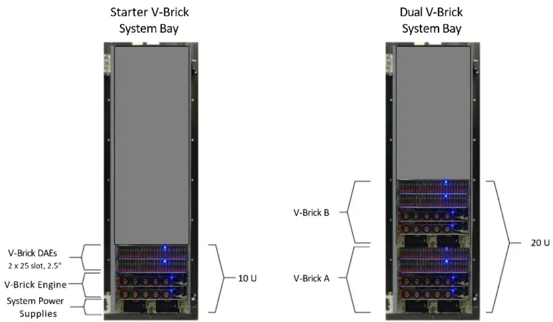
All VMAX 250F V-Bricks include a base capacity of 11TBu. Capacity is delivered via flash drives sizes of 960GB, 1.92TB, 3.84TB, 7.68TB, and 15.36TB, and is upgradeable in increments of 11TBu Flash Capacity Packs. The VMAX 250F V-Brick engines contain 2 directors each with, 512GB, 1TB, or 2TB of memory and with dual 12 core processors per director. The VMAX 250F is shipped in a dual engine cabinet configuration. A VMAX 250F system cabinet can scale out to accommodate a maximum of 2 full V-Bricks and 100 drives per floor tile yielding up to 1PBu in only 20U of rack space. The remaining rack space can be taken by an additional VMAX 250F system or by customer hardware such as servers and switches.
The following diagram shows the VMAX 250F starter V-Brick system bay configuration along with a dual V-Brick system bay configuration:
Figure 4. VMAX 250F Starter V-Brick Configuration and Dual V-Brick System Bay
Open Systems V-Brick System Configurations for the VMAX 450F and VMAX 850F
All open system VMAX 450F / 850F configurations are also built with V-Bricks, which include compute and a base capacity of 53TBu. Capacity is delivered via flash drives sizes of 960GB, 1.92TB and 3.84TB, and is upgradeable in increments of 13TBu Flash Capacity Packs. The 450F and 850F Engines contain 2 directors each with 1TB or 2TB of memory and with dual processors per director (8 core 2.6GHz for the 450F and 12 Core 2.7GHz for the 850F) and ship in dual engine cabinets. A single cabinet can accommodate 2 full V-Bricks and 480 drives per floor tile with up to 1 useable PB per cabinet. The VMAX 450F scales up to 4 V-Bricks and 2PBu per system and the 850F up to 8 V-Bricks and 4PBu per system.
The following diagram shows the VMAX 450F /850F starter V-Brick system bay configuration along with a dual V-Brick system bay configuration:
Figure 5. VMAX 450F / 850F Starter V-Brick Configuration and Dual V-Brick System Bay

The VMAX 450F model can scale out to four V-Bricks, which would require two systems bays (two floor tiles), while the VMAX 850F can scale out to eight V-Bricks, which would require four system bays (four floor tiles). System bays can be separated by up to 25 meters using optical connectors.
Open Systems V-Brick Front End Connectivity Options
For V-Bricks, engine cooling fans and power supplies can be accessed from the front, while the I/O modules, management modules, and control station can be accessed from the rear. Since the number of universal I/O modules used in the V-Brick engine depends on the customer's required functionality, some slots can remain unused.
There are multiple supported V-Brick front-end connections which are available to support several protocols and speeds. The table below highlights the various front-end connectivity modules available to the VMAX All Flash V-Brick:
Table 5. VMAX All Flash Open Systems V-Brick Engine Front End Connectivity Modules
| Connectivity Type | Module Type | Number of Ports | Mix With Protocols | Supported Speeds (Gbps) |
| Fibre Channel | 8 Gbps FC | 4 | SRDF | 2 / 4 / 8 |
| Fibre Channel | 16 Gbps FC | 4 | SRDF | 2/ 8 / 16 |
| SRDF | 10 GigE | 4 | iSCSI | 10 |
| SRDF | GigE | 2 | None | 1 |
| iSCSI | 10 GigE | 4 | SRDF | 10 |
| Cloud Array (CA) | 8 Gbps FC | 4 | FC, SRDF | 2 / 4 / 8 |
| eNAS | 10 GigE | 2 | None | 10 |
| eNAS | 10 GigE (Copper) | 2 | None | 10 |
| eNAS Tape Backup | 8 Gbps FC | 4 | None | 2 / 4 / 8 |
The quantity of V-Brick front-end ports scales, depending on protocol type, to a maximum of 32 for the VMAX 250F and 24 for the VMAX 450F / 850F.
On the four port 8 Gbps and 16 Gbps Fibre Channel IO modules, a customer can mix Fibre Channel host connectivity and SRDF using different ports. This is also true for the four port 10 GigE IO module where host iSCSI connectivity and GigE SRDF can be intermixed using different ports on the module. A customer can also mix Fibre Channel connectivity to the DELL EMC Cloud Array, along with host Fibre Channel connectivity, and SRDF using the 8 Gbps Fibre Channel modules. The GigE IO modules set aside for eNAS are dedicated and cannot be used for any other GigE connectivity type such as iSCSI and SRDF.
Other modules which are used by the V-Brick are shown in the table below:
Table 6. Other VMAX 250F / 450F / 850F Open Systems V-Brick Engine Modules
| Module Type | Purpose |
| Vault to Flash | Flash for Vault and Metadata (4 x 800 GB for VMAX 450F /850F, 3 x 400 GB or 800 GB for VMAX 250F) |
| Internal Fabric | Internal InfiniBand Fabric Connections |
| Backend SAS | Backend SAS connection to DAEs (12 Gbps for VMAX 250F, 6 Gbps for VMAX 450F / 850F) |
| Compression | Adaptive Compression Engine (ACE) and SRDF Compression |
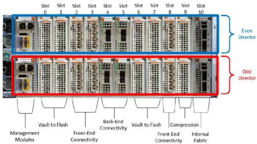
The VMAX 250F will use up to 3 Vault to Flash modules while the VMAX 450F and VMAX 850F systems use up to 4 Vault to Flash modules. The extra flash module required for the VMAX 450F and VMAX 850F systems is due to the larger usable capacities that VMAX 450F and 850F can scale to. The vault to flash modules usually will occupy slots 0, 1, and 6 on the VMAX 250F V-Brick engine while the vault to flash modules will usually occupy slots 0, 1, 6, and 7 on the VMAX 450F and VMAX 850F V-Brick engine.
The compression modules perform all operations for the Adaptive Compression Engine (ACE) as well SRDF compression for the VMAX All Flash systems. This results in an offloading of the compression task from using engine CPU core cycles. Each V-Brick will use a pair of compression modules (one per each V-Brick director). The compression modules are usually located in slot 7 on the VMAX 250F and slot 9 on the VMAX 450F / 850F.
The following figure depicts a typical layout for a VMAX 250F V-Brick engine:
Figure 6. Typical VMAX 250F V-Brick Engine Layout

Note: On the VMAX 250F, slot 5 is left empty (unused).
The following figure depicts a typical layout for a VMAX 450F / 850F V-Brick engine:
Figure 7. Typical VMAX 450F / 850F V-Brick Engine Layout
Open System VMAX All Flash Software Packaging
In order to simplify the software ordering and management process, VMAX All Flash will offer two different software packages for the VMAX 250F, VMAX 450F, and VMAX 850F in open systems environments.
The first option is known as the "F package" which can be considered a starter package. The F package includes HYPERMAX OS, Embedded Management, SnapVX and an AppSync starter pack. Any software title supported on VMAX All Flash can be added to the F package as an a la carte software addition. The VMAX All Flash models which use the F package are referred to as the VMAX 250F, VMAX 450F, and VMAX 850F.
The second option – the more encompassing package – is known as the "FX package". The FX package includes everything that's in the F package as well as SRDF/S, SRDF/A, SRDF/STAR, SRDF/Metro, CloudArray Enabler, D@RE, eNAS, Unisphere 360 and ViPR Suite. The FX is priced to offer a bundled discount over an equivalent F option which has many a la carte titles as additions. Customers can add any title supported on VMAX All Flash to the FX in an a la carte fashion as well, including ProtectPoint, the full AppSync suite, and DELL EMC Storage Analytics. The VMAX All Flash models which use the FX package are referred to as the VMAX 250FX, VMAX 450FX, and VMAX 850FX. The following table details what software is included in each VMAX All Flash package:
Table 7. VMAX All Flash Open Systems Software Packages
| Feature | F Package Included | F Package a la Carte | FX Package Included | FX Package a la Carte | Notes |
| HYPERMAX OS | √ | √ | Includes Migration Tools, VVOLS, QoS (3) | ||
| Embedded Management | √ | √ | Includes Unisphere for VMAX, Database Storage Analyzer, Solutions Enabler, SMI-S | ||
| Local Replication | √ | √ | Includes Timefinder SnapVX | ||
| AppSync Starter Pack | √ | √ | |||
| Remote Replication Suite (1) | √ | √ | Includes SRDF/S/A/STAR | ||
| SRDF/Metro (1) | √ | √ | |||
| Unisphere 360 | √ | √ | |||
| Cloud Array Enabler (1) | √ | √ | |||
| D@RE (2) | √ | √ | |||
| eNAS (1) (2) | √ | √ | |||
| ViPR Suite | √ | √ | Includes ViPR Controller and ViPR SRM | ||
| ProtectPoint | √ | √ | |||
| PowerPath | √ | √ | |||
| AppSync Full Suite | √ | √ | |||
| DELL EMC Storage Analytics | √ | √ |
(1) FX Package includes software licensing. Required hardware need to be ordered separately
(2) Factory configured. Must be enabled during the ordering process
(3) Includes host I/O limits
VMAX All Flash for Mainframe
For mainframe configurations, the VMAX All Flash brick is referred to as a "zBrick". Each initial mainframe zbrick comes pre-configured from DELL EMC manufacturing with its own system bay. Dual engine system bay configurations are exclusively used as additional zbricks are added to the system.
VMAX All Flash for mainframe is restricted to the VMAX 450F and 850F products. Both must run only 100% mainframe workloads as no mixing of mainframe and open systems workloads is allowed. The VMAX 250F does not support mainframe workloads.
Mainframe zBrick System Configurations for the VMAX 450F / 850F
All mainframe VMAX 450F / 850F zBricks include a base capacity of 53TBu. Capacity is delivered via flash drives sizes of 960GB, 1.92TB and 3.84TB, and is upgradeable in increments of 13TBu zCapacity Packs. The 450F and 850F zBrick engines contain 2 directors each with 1TB or 2TB of memory and with dual processors per director (8 core 2.6GHz for the 450F and 12 Core 2.7GHz for the 850F) and ship in dual engine cabinets. A single cabinet can accommodate two full zBricks and 480 drives per floor tile with up to 400 PBu per cabinet. The VMAX 450F scales up to four zBricks and 800TBu per system and the 850F up to eight zBricks and 1.7PBu per system. The mainframe zBrick does not support the Adaptive Compression Engine (ACE), therefore all system capacities are expressed in usable capacity.
Figure 8. VMAX 450F / 850F Starter zBrick Configuration and Dual zBrick System Bay
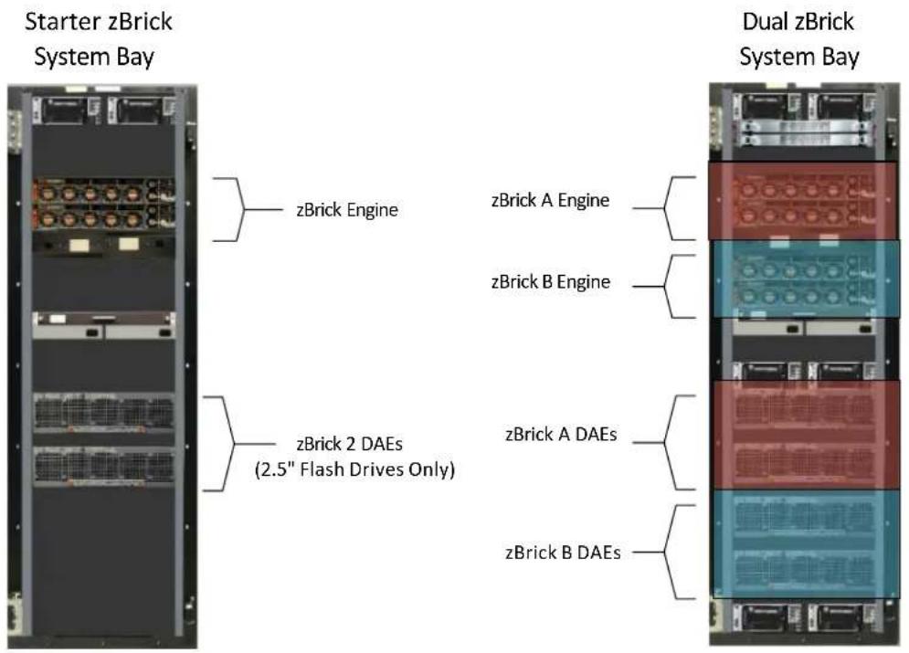
The VMAX 450F model can scale out to four zBricks, which would require two systems bays (two floor tiles), while the VMAX 850F can scale out to eight zBricks, which would require four system bays (four floor tiles). System bays can be separated by up to 25 meters using optical connectors.
Mainframe zBrick Front End Connectivity Options
For zBricks, engine cooling fans and power supplies can be accessed from the front, while the I/O modules, management modules, and control station can be accessed from the rear. Since the number of universal I/O modules used in the zBrick engine depends on the customer's required functionality, some slots can remain unused.
The zBrick supports FICON and SRDF front end connectivity. The table below highlights the various front-end connectivity modules available to the VMAX All Flash zBrick:
Table 8. VMAX All Flash Open Systems V-Brick Engine Front End Connectivity Modules
| Connectivity Type | Module Type | Number of Ports | Mix With Protocols | Supported Speeds (Gbps) |
| FICON | 16 Gbps FICON | 4 | Single / Multi Mode | 4 / 8 / 16 |
| SRDF | 16 Gbps Fibre Channel | 4 | None | 4 / 8 / 16 |
| SRDF | 8 Gbps Fibre Channel | 4 | None | 4 / 4 / 8 |
| SRDF | 10 GigE | 4 | None | 10 |
| SRDF | GigE | 2 | None | 1 |
The quantity of zBrick front-end ports scales to a maximum of 32 when SRDF is not being used. When SRDF is used in the configuration, one of the front end slots is taken by the SRDF compression module on each engine director. This limits the number of available zBrick front end ports to 24. By default, each zBrick comes with two FICON modules.
Table 9. Other VMAX 450F / 850F Mainframe zBrick Engine Modules
| Module Type | Purpose |
| Vault to Flash | Flash for Vault and Metadata (4 x 800 GB for VMAX 450F /850F) |
| Internal Fabric | Internal InfiniBand Fabric Connections |
| Backend SAS | Backend SAS connection to DAEs (6 Gbps for VMAX 450F / 850F) |
| Compression (Optional) | SRDF compression only |
The VMAX 450F and VMAX 850F systems use up to four Vault to Flash modules. The extra flash module required for the VMAX 450F and VMAX 850F systems is due to the larger usable capacities that VMAX 450F and 850F can scale to. The vault to flash modules will usually occupy slots 0, 1, 6, and 7 on the VMAX 450F and VMAX 850F zBrick engine.
The following figure depicts a typical VMAX 450F / 850F zBrick engine which is configured for SRDF:
Figure 9. Typical VMAX 450F / 850F zBrick Engine Layout with SRDF

When SRDF is used in the configuration, each zBrick will use a pair of SRDF compression modules (one per each zBrick director). The SRDF compression modules are usually located in slot 9 on the VMAX 450F / 850F. When SRDF is not used in the zBrick configuration, a front end module can be placed into slot 9 providing additional front end connectivity. The following diagram shows a typical non-SRDF zBrick engine configuration:
Figure 10. Typical VMAX 450F / 850F zBrick Engine Layout without SRDF

VMAX All Flash for Mainframe Software Packaging
Software for mainframe support comes in two packages, z/F, the basic package and z/FX, a larger bundle of more advanced features. Additionally, many software features for mainframe can be ordered "a la Carte". The packages are different to the standard all flash packages and represent the core functionalities used by the mainframe customer. The following table highlights the VMAX All Flash for Mainframe software packaging:
Table 10. VMAX All Flash for Mainframe Software Packages
| Feature | zF Package Included | zF Package a la Carte | zFX Package Included | zFX Package a la Carte | Notes |
| HYPERMAX OS | √ | √ | Includes Migration Tools, QoS | ||
| Embedded Management | √ | √ | Includes Unisphere for VMAX, Database Storage Analyzer, Solutions Enabler, SMI-S | ||
| Local Replication | √ | √ | Includes Timefinder SnapVX | ||
| Mainframe Essentials | √ | √ | |||
| Remote Replication Suite (1)(3) | √ | √ | Includes SRDF/S/A/STAR | ||
| Unisphere 360 | √ | √ | |||
| AutoSwap | √ | √ | |||
| D@RE (2) | √ | √ | |||
| zDP | √ | √ | |||
| GDDR (3) | √ | √ |
(1) zFX Package includes software licensing. Any additional required hardware needs to be ordered separately
(2) Factory configured. Must be enabled during the ordering process
(3) Use of SRDF/STAR for mainframe requires GDDR
SUMMARY
VMAX All Flash is a ground breaking all flash array designed for the most demanding and critical workloads in the enterprise data center. Its unique modular architecture allows it to massively scale while delivering predictable high performance regardless of the workload. Built into the array are complex algorithms which maximize flash performance, while greatly enhancing flash drive endurance. Its unique data services and highly available 6x9s architecture make it a premier choice for the enterprise environment where ease-of-use coupled with trusted dependability is an essential requirement.
REFERENCES
DELL EMC VMAX Local Replication Technical Note – P/N H13697
DELL EMC VMAX Unified Embedded NAS Technical Note – P/N H13904
DELL EMC VMAX Reliability, Availability, and Serviceability Technical Note – P/N H13807
DELL EMC VMAX SRDF/Metro Overview and Best Practices Technical Note – P/N H14556
DELL EMC VMAX3 and VMAX All Flash Quality of Service Controls for Multi-Tennant Environments


- ABSTRACT
- TABLE OF CONTENTS
- EXECUTIVE SUMMARY 5
- INTENDED AUDIENCE....5
- THE VMAX ALL FLASH FAMILY 5
- FLASH OPTIMIZATION ON THE VMAX ALL FLASH 11
- VMAX ALL FLASH DATA SERVICES 12
- VMAX ALL FLASH – HIGH AVAILABILITY AND RESILIENCE 14
- VMAX ALL FLASH CONFIGURATIONS FOR OPEN SYSTEMS....15
- VMAX ALL FLASH CONFIGURATIONS FOR MAINFRAME 19
- EXECUTIVE SUMMARY
- INTENDED AUDIENCE
- The VMAX All Flash Family
- Background
- Introducing the VMAX All Flash Arrays
- VMAX All Flash System Overview
- A Modular Building Block Architecture
- The Brick Overview
- Brick Engines
- Brick Engine CPU Core Configurations
- Brick Engine Cache Configurations
- Brick Drive Array Enclosures (DAEs)
- VMAX 250F Model V-Brick DAEs
- VMAX 450F and VMAX 850F Model Brick DAEs
- Important notes about VMAX All Flash brick DAE capacity
- FLASH OPTIMIZATION ON THE VMAX ALL FLASH
- VMAX All Flash Cache Architecture and Caching Algorithms
- Understanding Flash Cell Endurance
- VMAX All Flash Write Amplification Reduction
- Boosting Flash Performance with FlashBoost
- HYPERMAX OS
- VMAX ALL FLASH DATA SERVICES
- Remote Replication with SRDF
- Local Replication with TimeFinder SnapVX
- Consolidation of Block and File Storage Using eNAS
- Embedded Management (Embedded Unisphere for VMAX)
- VMAX All Flash – High Availability and Resilience
- VMAX All Flash Configurations for Open Systems
- Open Systems V-Brick System Configurations for the VMAX 250F
- Open Systems V-Brick System Configurations for the VMAX 450F and VMAX 850F
- Open Systems V-Brick Front End Connectivity Options
- Open System VMAX All Flash Software Packaging
- VMAX All Flash for Mainframe
- Mainframe zBrick System Configurations for the VMAX 450F / 850F
- Mainframe zBrick Front End Connectivity Options
- VMAX All Flash for Mainframe Software Packaging
- SUMMARY
- REFERENCES
Brand : EMC
Model : VMAX 850F
Category : Mainframe