
PP-AM200010 - Car radio Fusion - Free user manual and instructions
Find the device manual for free PP-AM200010 Fusion in PDF.


| Product Type | Car Audio Monoblock Amplifier |
| Brand | Fusion |
| Model | PP-AM200010 |
| Amplifier Class | Class D |
| Maximum Power Output | 2000 Watts |
| RMS Power (4 Ohms) | 600 Watts x 1 Channel @ 1% THD+N |
| RMS Power (2 Ohms) | 900 Watts x 1 Channel @ 1% THD+N |
| RMS Power (1 Ohm) | 1000 Watts x 1 Channel @ 1% THD+N |
| Frequency Response | 20 Hz - 320 kHz |
| Dimensions (L x W x H) | 436 x 279 x 60 mm (17.2 x 11.0 x 2.4 in) |
| Weight | Approx. 4.5 kg (10 lbs) |
| Fuse Rating | 40A x 3 (Total 120A) |
| Input Sensitivity | 200 mV - 4 V |
| Crossover Type | Low-Pass Filter (12 dB/octave) |
| Crossover Frequency Range | 32 Hz - 320 Hz |
| Subsonic Filter | Variable, 12 dB/octave |
| Bass Boost | Adjustable (0-18 dB typical) |
| Remote Level Control | Yes, via included remote controller |
| LED Indicators | Power (Green), Protection (Red) |
| Protection Circuits | Short Circuit, Thermal, Overload, DC Offset |
| Recommended Power Wire | 4 AWG or larger |
| Operating Voltage | 12 V DC (11-16 V) |
| Mounting | Ensure adequate ventilation; do not mount on subwoofer enclosure |
Frequently Asked Questions - PP-AM200010 Fusion
User questions about PP-AM200010 Fusion
0 question about this device. Answer the ones you know or ask your own.
Ask a new question about this device
Download the instructions for your Car radio in PDF format for free! Find your manual PP-AM200010 - Fusion and take your electronic device back in hand. On this page are published all the documents necessary for the use of your device. PP-AM200010 by Fusion.
USER MANUAL PP-AM200010 Fusion
POWERPLANT AMPLIFIER MANUAL
PP-AM300010
PP-AM200010
PP-AM100010
PP-AM120040
PP-AM60020
FUSGN®
CONTENTS
- AMPLIFIER SPECIFICATIONS ...... pg 4
• AMPLIFIER INSTALLATION....pg 5 - FOUR CHANNEL AMPLIFIER ...... pg 6
- TWO CHANNEL AMPLIFIER ......pg 8
• MONOBLOCK AMPLIFIERS....pg 10
• TROUBLESHOOTING ......pg 12
RECORD YOUR PRODUCT DETAILS HERE:
MODEL NUMBER DATE OF PURCHASE
AFFIX RECEIPT HERE
Version 1.0
22
3
AMPLIFIER SPECIFICATIONS
| PP-AM300010 (Monoblock) PP-AM200010 (Monoblock) | ||
| Class D-Class D-Class | ||
| Max Power Rating 3000 Watts 2000 Watts | ||
| Frequency Response 20Hz - 320kHz 20Hz - 320kHz | ||
| Dimensions (mm) 436(L) x 278(W) x 60(H) 436(L) x 279(W) x 60(H) | ||
| Power Ratings | 850 Watts RMS per Channelø 4 Ohms 1% THD+N1300 Watts RMS per Channelø 2 Ohms 1% THD+N1500 Watts RMS x 1 Channelø 1 Ohms 1% THD+N | 600 Watts RMS x 1 Channelø 4 Ohms 1% THD+N900 Watts RMS x 1 Channelø 2 Ohms 1% THD+N1000 Watts RMS x 1 Channelø 1 Ohms 1% THD+N |
| PP-AM100010 (Monoblock) PP-AM120040 (4 Channel) | ||
| Class D-Class Class AP | ||
| Max Power Rating 100 | 00 Watts 1200 Watts | |
| Frequency Response 2 | 0Hz -320kHz 10Hz - 100kHz | |
| Dimensions [mm] 386 | L) x 278[W] x 60[H] 546[L] x 278 | W) x 60[H] |
| Power Ratings | 400 Watts RMS x 1 Channelø 4 Ohms 1% THD+N620 Watts RMS x 1 Channelø 2 Ohms 1% THD+N | 125 Watts RMS per Channelø 4 Ohms 1% THD+N185 Watts RMS per Channelø 2 Ohms 1% THD+N330 Watts RMS Bridged Channelsø 4 Ohms 1% THD+N |
| PP-AM60020 (2 Channel) | |
| Class Class AB | |
| Max Power Rating 600 Watts | |
| Frequency Response 10Hz - 100kHz | |
| Dimensions [mm] 436 (L) x 278(W) x 60(H) | |
| Power Ratings | 125 Watts RMS per Channelø 4 Ohms 1% THD+N190 Watts RMS per Channelø 2 Ohms 1% THD+N390 Watts RMS Bridged Channelsø 4 Ohms 1% THD+N |
ACCEPTABLE AMPLIFIER LOADS
| Model 4 Ohm 2 Ohm 1 Ohm | |||
| PP-AM120040 | YES*1 | YES*2 | NO |
| PP-AM60020 | YES*1 | YES*2 | NO |
| PP-AM300010 | YES YES YES | ||
| PP-AM200010 | YES YES YES | ||
| PP-AM100010 | YES YES | NO | |
| *1 Per Channel and Bridged Channel(s), *2 Per Channel ONLY | |||
NB : PP-AM100010 IS NOT 1 Ohm STABLE
AMPLIFIER INSTALLATION
INSTALLATION WARNING
- Ensure the 12V lead is disconnected from the battery before you connect any new equipment.
- Ensure the mounting location will not interfere with the gas tank, brake lines or electrical wiring.
- Ensure the Amplifier is securely fastened to the vehicle to prevent damage in the event of an accident.
- Ensure all wiring is protected to avoid pinching or crushing which could result in damage to the audio system.
- Ensure the mounting location has sufficient air flow around the amplifier. If the amplifier is mounted in an enclosed space a 3" fan with ducting should be used to aid in air flow.
- Do not mount any amplifier on a subwoofer enclosure as extended exposure to vibration may cause malfunction of the amplifier.
- Ensure you use the recommended gauge wire/cable for all amplifier connections.
Wiring
Ensure the audio system is turned off before making any connections to the amplifier, speakers or source unit. Failure to do so could result in permanent damage to the audio system.
When wiring the FUSION amplifier ensure that the cable is protected from sharp objects and always use rubber grommets when wiring through metal panels. Ensure all terminals and connections are protected from the vehicle chassis and from each other as failure to do so could result in permanent damage to the audio system.
FOUR CHANNEL AMPLIFIER
PP-AM120040
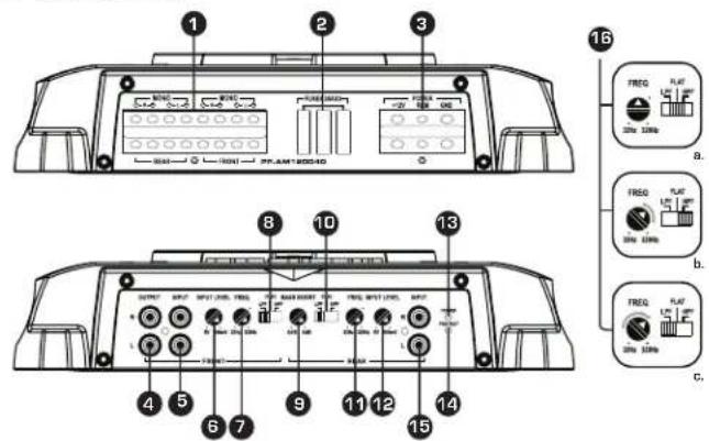
1. Speaker Output Connections
Ensure that the speakers are connected observing correct polarity.
2 Ohm minimum speaker impedance for stereo operation
4 Ohm minimum speaker impedance for bridged operation
2. Fuses
Ensure fuses are replaced with the same type and rating.
3. Power
FUSION amplifiers should be connected directly to the 12V battery terminal with an inline fuse or circuit breaker as close to the battery as possible.
Ground
When grounding/carthing your amplifier ensure that the location is a good source of ground (preferably the floor pan). Make sure the metal is clean of paint etc, as a poor earth could damage your audio system.
Remote Turn On
This connection turns the amplifier ON and should be connected to the remote turn on lead from the Head Unit. If one is not available a switched 12V source must be used.
4. Output Connectors
Line level output for connection to an additional amplifier
5. Front Input Connectors
Choose the correct length RCA interconnects and run them to the RCA outputs of the source unit. Avoid running beside other looms and or power cable.
56
6. Front Input Level
This control is used to match the input level of the amplifier to the output level of your source unit 1. Turn the amplifier level to zero.
2. Turn the volume of the source unit to 34 and the bass and treble to zero.
3. Adjust the level control until the desired maximum volume is achieved without distortion.
4. Failure to follow these steps may cause permanent damage to the audio system.
7. Frequency Control - Front X-Over
12dB/Octave crossover, variable from 32Hz to 320Hz. (For adjustment procedure see 16.)
8. Filter Selector - Front X-Over
LPF - Select for subwoofer[s].
Flat - Select for full range speakers.
HPF - Select for mid/full range speakers when using a subwoofer in the system.
9. Bass Boost Control
Adjust the Bass Boost to the desired level.
10. Filter Selector - Rear X-Over
LPF - Select for subwoofer(s).
Flat - Select for full range speakers.
HPF - Select for mid/full range speakers when using a subwoofer in the system.
11. Frequency Controller - Rear X-Over
12dB/Octave crossover, variable from 32Hz to 320Hz.
For adjustment procedure see 16.
12. Rear Input Level
This control is used to match the input level of the amplifier to the output level of your head unit
- Turn the amplifier level to zero.
- Turn the volume of the head unit to 1/2 and the bass and treble to zero.
- Adjust the level control until the desired maximum volume is achieved without distortion.
- Failure to follow these steps may cause permanent damage to the audio system.
13. Power ON LED
Amplifier is operational when illuminated.
14. Protection LED
When illuminated the amplifier is in protection mode due to any of the following fault conditions. Short Circuit, Thermal, Output Short, DC Offset.
15. Rear Input Connectors
Choose the correct length RCA interconnects and run them to the RCA outputs of the source unit. Avoid running beside other looms and or power cable.
16. Setting the Crossover
a. Diagram for crossover settings for 5° or larger full range speakers,
b. Diagram for crossover settings for mid/full range speakers when using a subwoofer in your system.
c. Diagram for crossover settings for subwoofers.
NB: The gray section indicates acceptable frequency ranges.
TWO CHANNEL AMPLIFIER
PP-AM60020

1. Speaker Output Connections
Ensure that the speakers are connected observing correct polarity.
2. Fuses
Ensure fuses are replaced with the same type and rating.
3. Power
FUSION amplifiers should be connected directly to the 12V battery terminal with an inline fuse or circuit breaker as close to the battery as possible.
Ground
When grounding/earthing your amplifier ensure that the location is a good source of ground (preferably the floor pan). Make sure the metal is clean of paint etc, as a poor earth could damage your audio system.
Remote Turn On
This connection turns the amplifier on and should be connected to the remote turn on lead from the Head Unit. If one is not available a switched 12V source must be used.
4. Output Connectors
Line level output for connection to an additional amplifier.
88
5. Input Connectors
Choose the correct length RCA interconnects and run them to the RCA outputs of the source unit. Avoid running beside other looms and or power cable.
6. Input Level
This control is used to match the input level of the amplifier to the output level of your head unit 1. Turn the amplifier level to zero.
- Turn the volume of the head unit to 314 and the bass and treble to zero.
- Adjust the level control until the desired maximum volume is achieved without distortion.
- Failure to follow these steps may cause permanent damage to the audio system.
7. Frequency Control
12dB/Octave crossover, variable from 32Hz to 320Hz.
(For adjustment procedure see 12.)
8. Filter Selector - Crossover
LPF - Select for subwoofer[s].
Flat - Select for full range speakers.
HPF - Select for mid/full range speakers when using a subwoofer in the system.
9. Boost Control
Adjust the Bass Boost to the desired level.
10. Power ON LED
Amplifier is operational when illuminated.
11. Protection LED
When illuminated the amplifier is in protection mode due to any of the following fault conditions. Short Circuit, Thermal, Output Short, DC Offset.
12. Setting the Crossover
a. Diagram for crossover settings for 5° or larger full range speakers.
b. Diagram for crossover settings for mid/full range speakers when using a subwoofer in your system.
c. Diagram for crossover settings for subwoofers.
NB: The gray section indicates acceptable frequency ranges.
9
MONOBLOCK AMPLIFIERS
PP-AM100010, PP-AM200010, PP-AM300010

1. Speaker Output Connections
Ensure that the speakers are connected observing correct polarity.
2. Fuses
| Ensure fuses are replaced with the same type and rating (PP-AM100010 Pictured Above). | |||
| PP-AM100010 | 25A | x 3 | |
| PP-AM200010 | 40A | x 3 | |
| PP-AM300010 | 40A | x 4 | |
3. Power
FUSION amplifiers should be connected directly to the 12V battery terminal with an inline fuse or circuit breaker as close to the battery as possible.
Ground
When grounding/earthing your amplifier ensure that the location is a good source of ground (preferably the floor pan). Make sure the metal is clean of paint etc, as a poor earth could damage your audio system.
Remote Turn On
This connection turns the amplifier on and should be connected to the remote turn on lead from the Head Unit. If one is not available a switched 12V source must be used.
1010
4. Output Connectors
Line level output for connection to an additional amplifier
5. Input Connectors
Choose the correct length RCA interconnects and run them to the RCA outputs of the source unit. Avoid running beside other looms and or power cable.
6. Input Level
This control is used to match the input level of the amplifier to the output level of your head unit 1. Turn the amplifier level to zero.
2. Turn the volume of the head unit to 34 and the bass and treble to zero.
3. Adjust the level control until the desired maximum volume is achieved without distortion.
4. Failure to follow these steps may cause permanent damage to the audio system.
7. Frequency Control
12dB/Octave Low Pass crossover, variable from 32Hz to 320Hz.
8. Subsonic Filter
This is a variable control that filters out all sub bass frequencies below the set point at 12dB/Octave.
9. Boost Control (Rear)
Adjust the Bass Boost to the desired level
10. Remote Level Control
Connect the Remote Level Controller using the supplied cable.
11. Power ON LED
Amplifier is operational when illuminated.
12. Protection LED
When illuminated the amplifier is in protection mode due to any of the following fault conditions. Short Circuit, Thermal, Output Short, DC Offset.
11
TROUBLESHOOTING
| PROBLEM POSSIBLE REASON SOLUTION | ||
| Amplifier not switching on. Power LED not 'ON' | • No +12V to power wire • | Check fuses and connections to battery |
| • No power to remote wire | • Check Remote Turn ON connection(s) to head unit | |
| • Fuse broken • Replace fuse with correct type and amperage | ||
| Amplifier not working, but status LED 'ON' | • Fuse on amplifier blown • | Replace fuse with correct type and amperage |
| • Amplifier too hot • Move amplifier to vented area • Turn head unit down | ||
| • Speaker wires shorted • | Check that there are no speaker wires shorted to another wire or to the vehicle chassis | |
| No sound | • RCA Signal • Check RCA connection to head unit | |
| • Gain control not set up • | Ensure you have set up the amplifier gain level control | |
| • Head Unit • Check head unit volume level | ||
| • Amplifier • Check all power, remote on and groundconnections | ||
| • Speakers • Check speakers for wire shorts | ||
NOTES
1212
13
NOTES
PUBLISHED BY FUSION ELECTRONICS LIMITED © Copyright 2009 by FUSION Electronics Limited. At rights reserved, specifications and design are
subject to change without notice

YOU CAN HELP PROTECT THE ENVIRONMENT! Please remember to respect the local requirements: Hand in the non working electrical equipment to an appropriate waste disposal center.
1414
15
FUSON®
Specifications and design are subject to change without notice
- POWERPLANT AMPLIFIER MANUAL
- CONTENTS
- AMPLIFIER SPECIFICATIONS
- AMPLIFIER INSTALLATION
- INSTALLATION WARNING
- Wiring
- FOUR CHANNEL AMPLIFIER
- Speaker Output Connections
- Fuses
- Power
- Ground
- Remote Turn On
- Output Connectors
- Front Input Connectors
- Front Input Level
- Frequency Control - Front X-Over
- Filter Selector - Front X-Over
- Bass Boost Control
- Filter Selector - Rear X-Over
- Frequency Controller - Rear X-Over
- Rear Input Level
- Power ON LED
- Protection LED
- Rear Input Connectors
- Setting the Crossover
- TWO CHANNEL AMPLIFIER
- Input Connectors
- Input Level
- Frequency Control
- Filter Selector - Crossover
- Boost Control
- Power ON LED
- Protection LED
- Setting the Crossover
- MONOBLOCK AMPLIFIERS
- Subsonic Filter
- Boost Control (Rear)
- Remote Level Control
- Power ON LED
- Protection LED
- NOTES
Brand : Fusion
Model : PP-AM200010
Category : Car radio