
IP5000 - Phone HITACHI - Free user manual and instructions
Find the device manual for free IP5000 HITACHI in PDF.


| Type | IP Phone |
| Brand | Hitachi |
| Model | IP5000 |
| Dimensions (approx.) | 220 x 180 x 100 mm |
| Weight (approx.) | 0.8 kg |
| Power Supply | Power over Ethernet (PoE) or AC adapter (9V DC) |
| Display | Monochrome LCD with backlight |
| Keypad | Alphanumeric with navigation keys |
| Speakerphone | Full-duplex speakerphone |
| Headset Jack | RJ-9 headset port |
| Network Interface | 2 x RJ-45 10/100 Ethernet ports |
| VoIP Protocols | SIP |
| Audio Codecs | G.711, G.729, G.722 |
| Feature Keys | 6 programmable keys |
| Main Functions | Call hold, transfer, conference, voicemail, call forwarding, caller ID |
| Mounting | Desk stand or wall mountable |
| Cleaning | Wipe with a soft, dry cloth; do not use liquids |
| Safety | Keep away from moisture; avoid direct sunlight |
| Spare Parts | Handset, handset cord, Ethernet cable, AC adapter |
| Repairability | User replaceable handset and cables; consult service for internal parts |
| General Information | Designed for office use; supports multiple lines and call management |
Frequently Asked Questions - IP5000 HITACHI
User questions about IP5000 HITACHI
0 question about this device. Answer the ones you know or ask your own.
Ask a new question about this device
Download the instructions for your Phone in PDF format for free! Find your manual IP5000 - HITACHI and take your electronic device back in hand. On this page are published all the documents necessary for the use of your device. IP5000 by HITACHI.
USER MANUAL IP5000 HITACHI
WirelessIP 5000 Administrator Manual (v2.0.0)
Hitachi Cable, Ltd.
1. ADMIN MENU .... 1
1.1 Network....2
1.1.1 Network....2
1.1.1.1 Basic Info 3
1.1.1.2 WLAN....3
1.1.1.3 WEP 4
1.1.1.4 Authentication....5
1.1.1.5 TCP/IP....6
1.1.1.6 SIP Outb Proxy 6
1.1.1.7 NAT Traversal 7
1.1.1.8 IP DiffServ 8
1.1.1.9 Coder....9
1.1.1.10 Jitter Buf Size....9
1.1.2 SIP 10
1.1.2.1 User Account....10
1.1.2.2 Server Settings 11
1.1.2.3 Outbound Proxy 11
1.1.2.4 Expire....12
1.1.3 Network Reload 12
1.1.4 Certs Manager....13
1.1.5 Site Scan....16
1.1.6 Ping Test 18
1.1.6.1 Manual 18
1.1.6.2 1st Proxy ....18
1.1.6.3 2nd Proxy....19
1.1.6.4 Gateway 20
1.1.6.5 TFTP server....20
1.2 Password 21
1.2.1 Admin Password 21
1.2.2 User Pwd Reset 22
1.3 Upgrade....23
1.3.1 Program....23
1.3.2 Configuration 24
1.3.3 Setup....25
1.3.3.1 TFTP server....26
1.3.3.2 Auto Upgrade....26
1.4 Syslog....27
1.5 Web Server 28
1.6 Phone Reset....29
1.7 Statistics....29
2. 802.1X (EAP-TLS) CERTIFICATE INSTALLATION METHODS....30
2.1 Installation Procedures 802.1x Certificate....30
2.1.1 Root Certificate 30
2.1.2 Private Certificate....31
3. BOOT-ROM MENU....34
3.1 Opening the boot-ROM menu....34
3.2 Network settings....34
3.2.1 Manual IP 35
3.2.2 DHCP 37
3.3 WLAN settings 38
3.3.1 SSID 38
3.3.2 WEP key 39
3.4 Boot-ROM upgrade 41
3.5 Software upgrade....43
3.6 Closing the Boot-ROM menu....44
4. TROUBLESHOOTING ....45
4.1 General....45
1. Admin menu
Reference: Please refer to the "WirelessIP 5000 User's Manual" for information on the names of the various WirelessIP 5000 buttons.
Required settings are made when using the phone. Only Administrators are able to set items on the Admin menu.
1
Press the LeftSoft key and select the menu.
Select "5. Setting".
From the Settings menu, select "2. Phone Lock".
Select "1. KeyLock password".
When you select "1. KeyLock password", the system asks you for the current password. Enter the Admin password. The default value is 000000.

1.1 Network
1
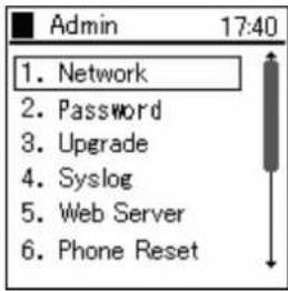
Either press the "1" on the number pad or select "1. Network", then press the Ⓑ key.
1.1.1 Network
You can check the settings for the type of connected network as well as information about settings.
1
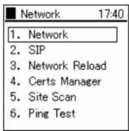
Select "1. Network" from the Network menu.
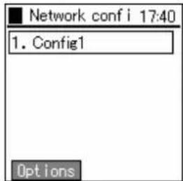
A list of the configurations is displayed.
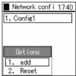
To add Config, press the LeftSoft key to select the sub-menu, then select "1. Add" and press the Key. To reset Config, select "2. Reset" and press the Key.
At most five configurations can be stored.
1.1.1.1 Basic Info
The WirelessIP 5000 can set the network for each AP (ESS-IS) (Dynamic Networking Binding function). You can set the priority of the various configurations here.
| 1 | Select "1. Basic Info" from the Config menu. | 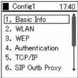 |
| 2 | Using the LeftSoft key, select "Edit" and "Join Method".Use the keys and select "AUTO" or "MANUAL". | 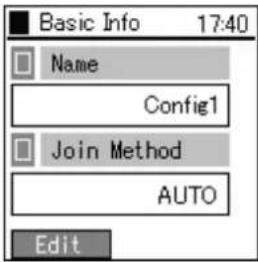 |
| 3 | When selecting "MANUAL", priority sequence can be changed by selecting "3. Up" or "4. Down" from the sub-menu on the Config list screen. | 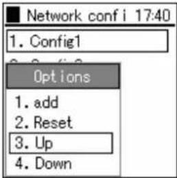 |
1.1.1.2 WLAN
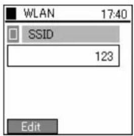
You can set the configuration for connection to wireless LAN, and create the SSID which identifies an access point.
| 1 | Select "2. WLAN" from the Config menu. | 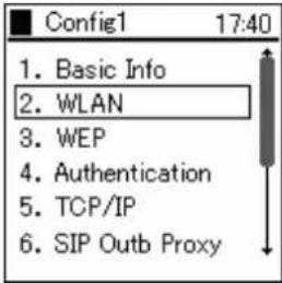 |
2
Displays SSID.
When blank, the connection is made to the access point where the radio waves are the strongest.
1.1.1.3 WEP
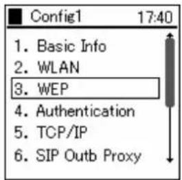
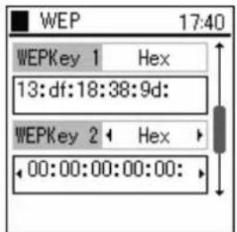
WEP key is used for authentication and encryption. WirelessIP 5000 supports 64/128/256 bit WEP key.
1
Select "3. WEP" from the Config menu.
2
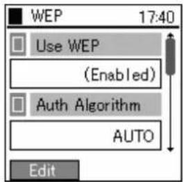
Using the LeftSoft key, select "edit."
For "Use WEP" use the △ keys to select "(Enable)" or "(Disable)".
3
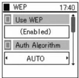
For "Auth Algorithm" use the ◀▶ keys to select either "AUTO", "Open System", or "Shared Key".
4
Enter the WEP key in either hexadecimal or Asc format.
| Bit | Hex | Asc |
| 256 bit 232 bit | 29 | characters |
| 128 bit 104 bit | 13 | characters |
| 64 bit 40 bit 5 | characters |
1.1.1.4 Authentication
Authentication related settings
| 1 | Select “4. Authentication” from the Config menu. | 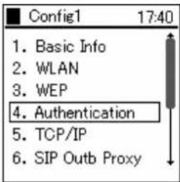 |
| 2 | Using the LeftSoft key, select “edit.”For “Mode” use the keys and select “8021X-MD5”, 8021X-TLS”, 8021X-PEAP”, “8021X-TTLS”, “WEB” or “None” settings. | 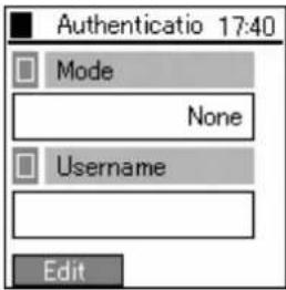 |
1.1.1.5 TCP/IP
You can set the IP address, subnet mask, default gateway, and DNS.
| 1 | Select “5. TCP/IP” from the Config menu. | 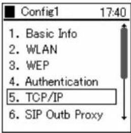 |
| 2 | TCP/IP Information displays: Use DHCP, IP Address, Netmask, Gateway, DNS1, and DNS2.If you want to set the IP address manually, deactivate DHCP.Enter the appropriate DNS (primary and secondary). | 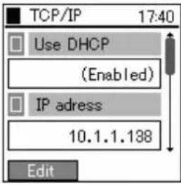 |
1.1.1.6 SIP Outb Proxy
You can set the Outbound Proxy server settings.
Depending on the system configuration, however, it sometimes is unnecessary to set it.
| 1 | Select “6. SIP Outb Proxy,” from the Config menu. | 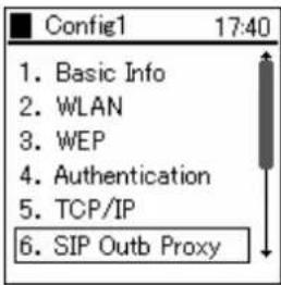 |
| 2 | A prompt will appear to enter the IP address for the SIP Outbound Proxy.Enter the IP address. | 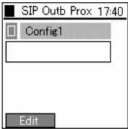 |
1.1.1.7 NAT Traversal
The WirelessIP 5000 supports both UPnP and StaticNAT, and it is possible to call from within the LAN to outside the LAN through NATBox. When doing so, you can set the UPnP and StaticNAT to match the settings of the NATBox being connected to.
| 1 | Select “7. NAT Traversal” from the Config menu. | 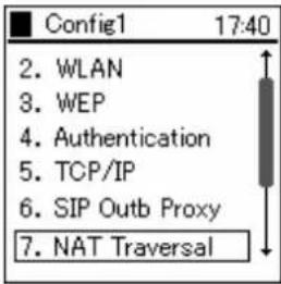 |
| 2 | Select “1. Mode” from the NAT Traversal menu. | 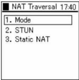 |
| Select SNAT, UPnP, STUN, or deactivate.When you press the ☑ key, the selected value is applied. | 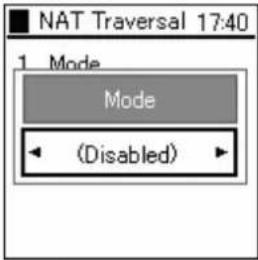 | |
| 3 | Select “2. STUN” from the NAT Traversal menu.Enter the Server IP and Port values. | 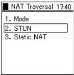 |
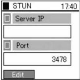 | ||
| 4 | Select “3. Static NAT” from the NAT Traversal menu.Enter the Ext IP and Start Port values. | 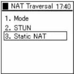 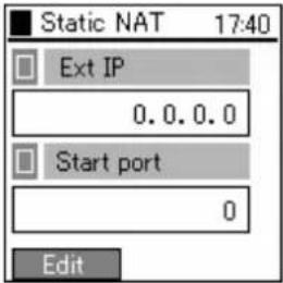 |
1.1.1.8 IP DiffServ
IP Diffserv sets the priority control settings.
| 1 | Select “8. IP DiffServ” from the Config menu. | 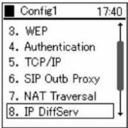 |
| 2 | Enter the value for the “Signal DSCP” and “Voice DSCP” setting using hexadecimal numbers.Note!!!) Enter a value between the 0x00 and 0x3F. | 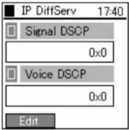 |
1.1.1.9 Coder
You can set the CODEC (priority and transmission interval) to match the system configuration.
| 1 | Select “9. Coder” from the Config menu. | 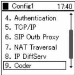 |
| 2 | Select the appropriate item from the Coder menu. | 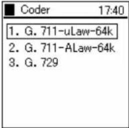 |
| Set Priority (1-3) and Multi-frame (20ms-40ms). | 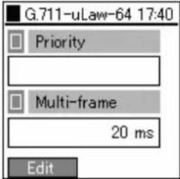 |
1.1.1.10 Jitter Buf Size
Taking into consideration your system configuration, you can optionally set the jitter buffer size.
| 1 | Select “0. Jitter Buf size” from the Config menu. | 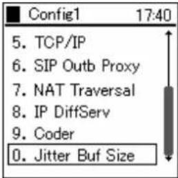 |
| 2 | Configure Jitter Buf Size. | 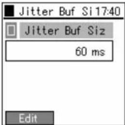 |
1.1.2 SIP
You can set items related to telephony. SIP configures call control.
1 Select "2. SIP" from the Network menu.
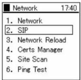
1.1.2.1 User Account
1 Select "1. User Account" from the SIP menu.
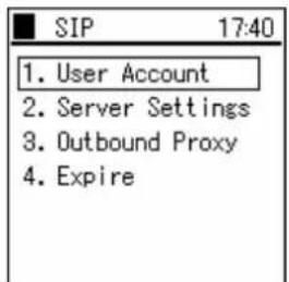
2 User Account Information displays: Display Name, Phone Number, User ID, and URL Scheme
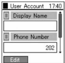
Although the Phone Number is required, enter the Display Name, User ID, and URL Scheme as deemed necessary.
1.1.2.2 Server Settings
| 1 | Select “2. Server Settings” from the SIP menu. | 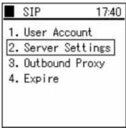 |
| 2 | Server Settings Information displays: Domain/Realm, 1st Proxy, 1st Registrar, 2nd Proxy, and 2nd Registrar. | 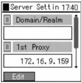 |
1.1.2.3 Outbound Proxy
You can set the Outbound Proxy server settings.
Depending on the system configuration, however, it sometimes is unnecessary to set it.
| 1 | Select “3. Outbound Proxy” from the SIP menu. | 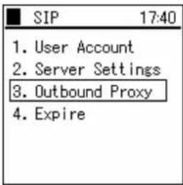 |
| 2 | Enter the Outbound Proxy’s IP Address. | 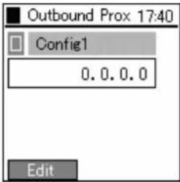 |
1.1.2.4 Expire
'Regist Expire Time', 'Session Timer', and 'Presence Expire Timer' can be set.
| 1 | Select “4. Expires” from the SIP menu. | 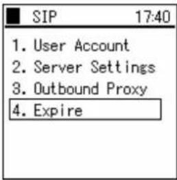 |
| 2 | Set Regist Expire, Session Expire, and Presence Expire. | 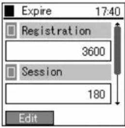 |
1.1.3 Network Reload
When taking various actions such as changing settings, adding and deleting configurations, you can manually perform a reload.
| 1 | Select “3. Network Reload” from the Network menu. | 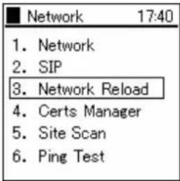 |
| 2 | Use the keys and select “Auto” or “Config”. | 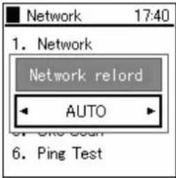 |
1.1.4 Certs Manager
When running 802.1x (EAP-TLS, PEAP, TTLS), root certificate and private certificate information can be imported and checked.
| 1 | Select “4. Certs Manager” from the Network menu. | 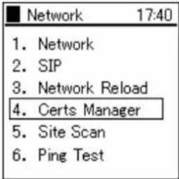 |
| 2 | Select “ 1. View RootCA” from the Certs Manager menu.View RootCA Information displays: CN, Issuer, Not Before, Not After, Serial, Signature, Subject, Version, and SPubKeyAlgorithm. | 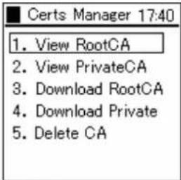 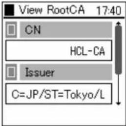 |
| 3 | Select “2. View RootCA” from the Certs Manager menu.View PrivateCA Information displays: CN, Issuer, Not Before, Not After, Serial, Signature, Subject, Version, and SPubKeyAlgorithm. | 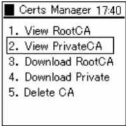 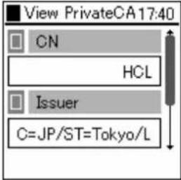 |
4
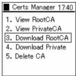
Select "3. Download RootCA" from the Certs Manager menu.
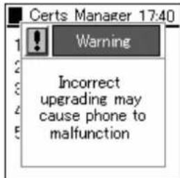
A warning message is displayed.
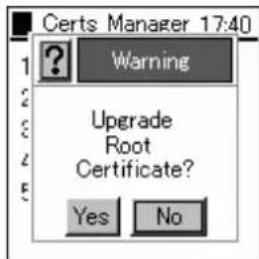
Use the □ keys and select "Yes" or "No".
If "Yes" is selected, the IP Address of the download TFTP server will be asked to be entered. Download starts after entering the IP address and pressing the Ⓞ key.
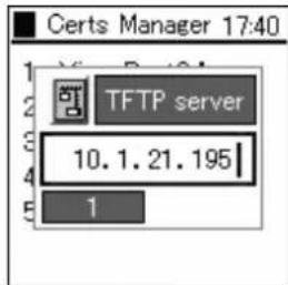
| 5 | Select “4. Download PrivateCA” from the Certs Manager menu. | 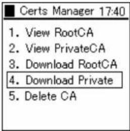 |
| If the PrivateCA is not downloaded, a warning message as listed on the right will display. | 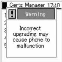 | |
| Use the ☑ keys and select “Yes” or “No”. | 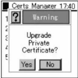 | |
| If “Yes” is selected, the IP Address of the download TFTP server will be asked to be entered. Download starts after entering the IP address and pressing the ☑ key. | 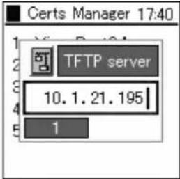 | |
| 6 | Select “5. Delete CA” from the Certs Manager menu. | 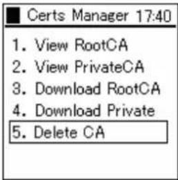 |
| Use the ☑ keys and select “RootCA”, “PrivateCA”, “Delete All”. | 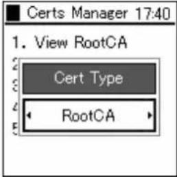 |
1.1.5 Site Scan
Information on signals detected can be displayed.
| 1 | Select “5. Site Scan” from the Network menu. | 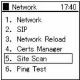 |
| 2 | A message is displayed during the search.The SSID for access points that where detected during the scan are displayed. If you want to see detailed information, select the SSID and press the [IMAGE].Note!!!) At most 10 access points can be displayed. |  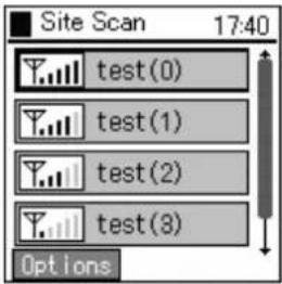 |
| 3 | To refresh the Site Scan Information, press the LeftSoft key to select the sub-menu, then select "1. Refresh".Site Scan reopens. | 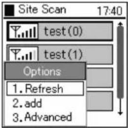  |
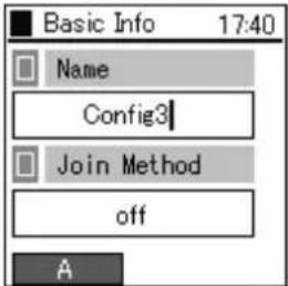
| 4 | Refer to the list of SSID's for detected access points, and select the SSID you would like to connect to (by moving the cursor). Select the submenu by pressing theLeftSoftkey and choose “2.Addition”.Follow the wizard as in the screen displayed to the right, and each of the network settings can be performed in order.For setting each item, refer to section 1.1.1.1 Basic Info (page 3). | 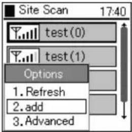 |
 | ||
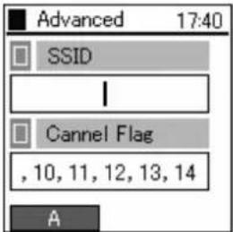
| 5 | When probing for particular SSIDs or Channels, press theLeftSoftkey to select the submenu, then choose “3. Advanced”.For example, when you enter the SSID displayed by the previously mentioned Scan in the SSID box on the right, and press®, a scan for that SSID commences and the results are displayed.Also, in the Channel Flag box, if you enter the number of the channel you would like to confirm and press the®key, a scan for that channel commences and the results are displayed. | 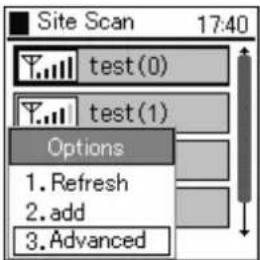 |
 |
1.1.6 Ping Test
You can confirm a signal by using the PING command.
| 1 | Select “2. Ping Test” from the Network menu. |
1.1.6.1 Manual
| 1 | Select “1. Manual” from the Ping Test menu. | 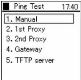 |
| 2 | Enter the IP address for Ping and press the Key to start the Ping. | 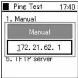 |
1.1.6.2 1st Proxy
| 1 | Select “2. 1st Proxy” from the Ping Test menu. | 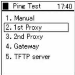 |
| 2 | If the 1st Proxy is not configured, the message in the right diagram displays. | 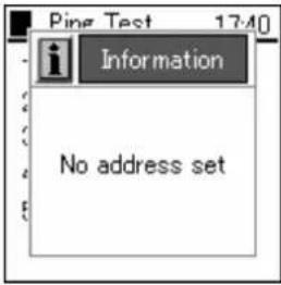 |
| 3 | 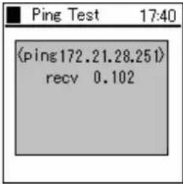 |
1.1.6.3 2nd Proxy
| 1 | Select “3. 2nd Proxy” from the Ping Test menu. | 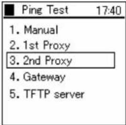 |
| 2 | If the 2nd Proxy is not configured, the message in the right diagram displays. | 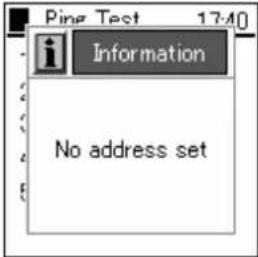 |
| 3 | 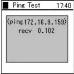 |
1.1.6.4 Gateway
| 1 | Select “4. Gateway” from the Ping Test menu. | 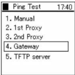 |
| 2 | 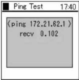 |
1.1.6.5 TFTP server
| 1 | Select “5. TFTP Server” from the Ping Test menu. | 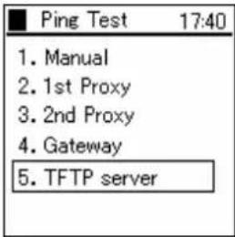 |
| 2 | 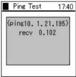 |
1.2 Password
| 1 | Select “2. Password” from the Admin menu. | 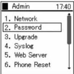 |
1.2.1 Admin Password
| 1 | Select “1. Admin Password” from the Password menu. | 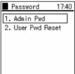 |
| 2 | When you select "1. Admin password", the system asks for the current password. Please enter the correct password. The default value is 000000. | 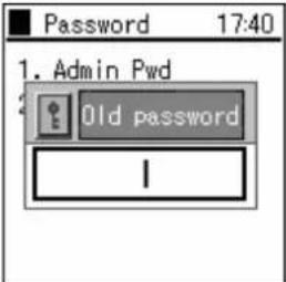 |
| 3 | When you input the correct password, the system asks you to input the new password. | 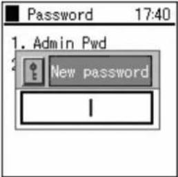 |
| 4 | For verification, the system asks you to input the new password a second time. | 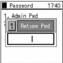 |
| 5 | When you input the password, a screen like that on the right is displayed for a few seconds. | 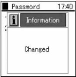 |
1.2.2 User Pwd Reset
| 1 | Select “2. User Pwd Reset” from the Password menu. | 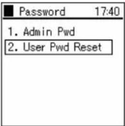 |
| 2 | With the ▶▶ keys select either "Yes" or "No". | 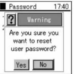 |
1.3 Upgrade
You can upgrade the software and configuration.
Warning: If there are major differences in the versions (i.e. Ver 1.x.x and Ver 2.x.x), the details of the old settings are not carried over.
| 1 | Select "3. Upgrade" from the Admin menu. |
1.3.1 Program
| 1 | Select “1. Program” from the Upgrade menu. | 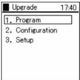 |
| 2 | A warning message is displayed.Use the keys and select “Yes” or “No”.(Refer to 1.3.2 Configuration) |  |
 |
1.3.2 Configuration
| 1 | Select “2. Configuration” from the Upgrade menu.When “2. Configuration” is selected, only the configuration is upgraded. | 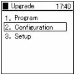 |
| 2 | A warning message is displayed. |  |
| 3 | Use the and select “Yes” or “No”. | 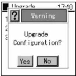 |
| 4 | If “Yes” is selected, enter the IP address of the TFTP server using the dial pad and LeftSoft key. | 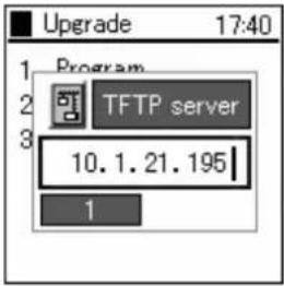 |
| 5 | A download screen, like the one to the right, will appear. | 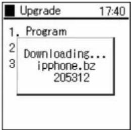 |
| 6 | After downloading, an upgrade confirmation screen will appear. | 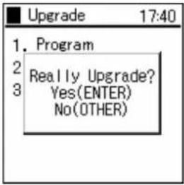 |
| 7 | Press the Key, and the program upgrade is performedIf you press any other button, the upgrade will be cancelled. | 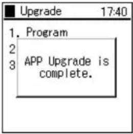  |
1.3.3 Setup
| 1 | Select “3. Setup” from the Upgrade menu. | ■ Upgrade 17:401. Program2. Configuration3. Setup |
1.3.3.1 TFTP server
| 1 | Select “1. TFTP server” from the Upgrade menu. | 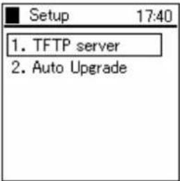 |
| 2 | When the input box appears, enter the TFTP server IP address.Save the setting by pressing the ☑ key | 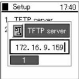 |
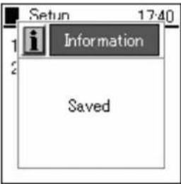 |
1.3.3.2 Auto Upgrade
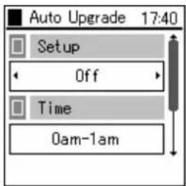
The firmware automatically upgrades randomly during the specified time intervals.
| 1 | Select “2. Auto Upgrade” from the Setup menu. | 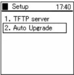 |
2
Select the settings using the ▶Key.
The time can be set (0am-1am - 11pm-0am).
The frequency can be set (Sun/Mon/Tue/Wed/Thu/Fri/Sat/Daily)
The settings can be configured (Enable/Disable)
Warning!: When "1. Invalid" is selected in user.ini, the auto upgrade function will not operate even if the menu settings are configured to "Use".
Warning!: When a terminal version is not configured in loadrun.ini, upgrade is conducted automatically.
Warning!: When the set time exceeds the WirelessIP time, the executed timing will be the following frequency.
1.4 Syslog
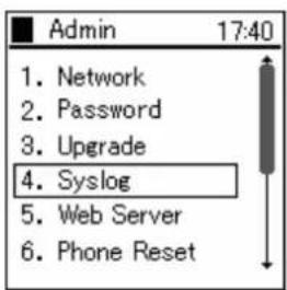
The WirelessIP 5000 can send information on the system log containing items such as events that occurred on the system and information to the Syslog server. Settings can be entered to match Syslog server configuration.
1
Select "4. Syslog" from the Admin menu.
2
Using the LeftSoft key, select "edit."
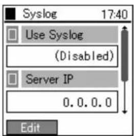
3
After setting User-Syslog to "Enable," the screen will look like the figure to the right and the Server IP can be entered.
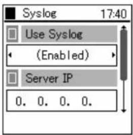
| 4 | Using the ▼key scroll to the bottom of the screen and input an appropriate Server IP and Server Port.Apply this by pressing the ◎key | 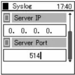 |
1.5 Web Server
It is possible to configure and access the boot-ROM and software from the network using a Web browser. You can turn the Web Server function on/off from here.
| 1 | Select “5. Web Server” from the Admin menu. | 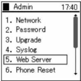 |
| 2 | Using the keys the web server can be turned on or off.Apply by pressing the key. | 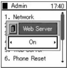 |
1.6 Phone Reset
| 1 | Select “6. Phone Reset” from the Admin menu. | 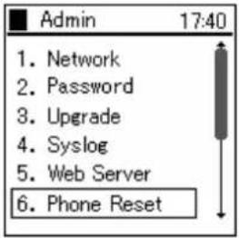 |
| 2 | Use the and select “Yes” or “No”.Select “Yes” to clear setting details. |  |
1.7 Statistics
| 1 | Select “2. SIP” from the Admin menu. | 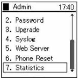 |
| 2 | Use the keys and select “Yes” or “No”. | 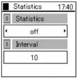 |
2. 802.1x (EAP-TLS) Certificate Installation Methods
2.1 Installation Procedures 802.1x Certificate
[Requirements]
The following are required. Issue these in advance and place in the root directory of the tftp server.
• Root Certificate (DER, CER [Base64 Encoding], PEM)
• Private Certificate (.pfx, p12)
* Please record and store the ID and Password when installing a Private Certificate.
* Warning: Depending on the situation, the ID/Passwords developed for Private Certificates may differ from the ID/Passwords used for connection, please take particular care in these circumstances. The following describes when the ID/Password differs during the Private Certificate install and connection authentication.
* The Root Certificate is necessary when using TLS, PEAP, and TTLS and the Private Certificate is necessary when using TLS.
2.1.1 Root Certificate
| 1 | Select “4. Certs Manager” from the Network menu. | 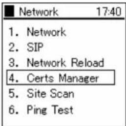 |
| 2 | Select “3. Download RootCA” from the Certs Manager menu. | 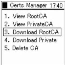 |
| 3 | Press the Key when the warning screen displays. | 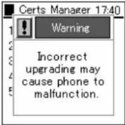 |
| 4 | A confirmation of whether to conduct an upgrade or not will appear.Use the keys and select “Yes”. | 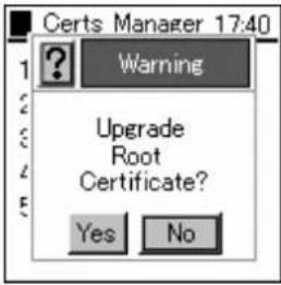 |
| 5 | Enter the IP address for the TFTP server. | 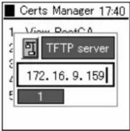 |
| 6 | Enter the file name to download.(Wait a short while)If an error messages displays, verify the environment and repeat 1 to 6. | 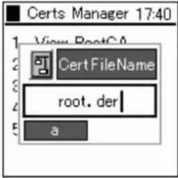 |
2.1.2 Private Certificate
| 1 | Press the LeftSoft key and select the menu. Either press the "6" on the number pad or select "6. Network", then press the Key. | 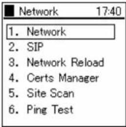 |
| 2 | A list of the configurations is displayed. Select the profile for use. | 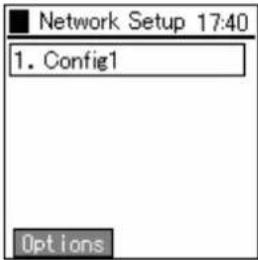 |
| 3 | Select “4. Authentication” from the Config menu. | 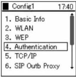 |
| 4 | Configure as follows and restart. Mode“None”, “WEB”, “8021X-TTLS”, “8021X-TLS”, “8021X-MD5”, “8021X-PEAP”Username(User ID) blank spacePassword(User Password) Password used for generating private certificates(*Note) This becomes the password for generating Private Certificates, so it does not matter if the User ID is blank. | 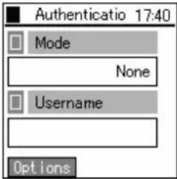 |
| 5 | Select “4. Certs Manager” from the Network menu. | 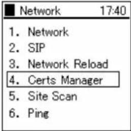 |
| 6 | Select “4. Download PrivateCA” from the Certs Manager menu. | 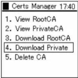 |
| 7 | Press thekey when the warning screen displays. |  |
| 8 | A question to whether conduct an upgrade will appear.Use the keys and select “Yes”. |  |
| 9 | Enter the IP address for the TFTP server. | 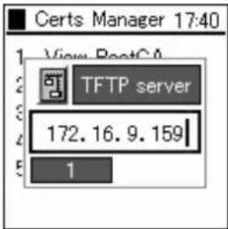 |
| 10 | Enter the file name to download.(Wait)If an error messages displays, verify the environment and repeat 1 to 9. | 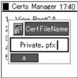 |
| 11 | After downloading, the Username and Password used for generating Private Certificates that was set in “4” is changed to the User ID and Password used for certification that is recorded in Radius.Mode Select the certification format‘None’, ‘WEB’, ‘8021X-TTLS’, ‘8021X-TLS’,‘8021X-MD5’, ‘8021X-PEAP’Username(User ID) * ID for Certification that is recorded in RADIUSPassword(User Password) *Password for Certification that is recorded in RADIUS(Caution)Please take care as the User ID and Password will become that which is recorded in Radius | 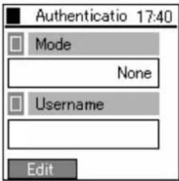 |
3. Boot-ROM menu
WirelessIP 5000 has both a normal mode and boot-ROM mode used for maintenance. In the boot-ROM mode, not only software but also a boot-ROM corresponding to the OS can be uploaded.
It is possible to upgrade from the boot-ROM menu on WirelessIP 5000. Upgrade using the following procedure.
Note!!!: Network settings on the boot-ROM menu are only valid in the boot-ROM menu. Network settings used during normal operation are set from the Admin menu.
3.1 Opening the boot-ROM menu
1 Press the End key and the LeftSoft key at the same time. Two seconds later, the boot-ROM menu will appear.
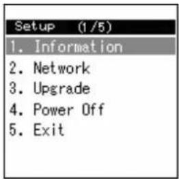
3.2 Network settings
Before upgrading, it is necessary to set the network settings. Network settings are entered from the Boot-ROM menu; it is not necessary to enter the settings from the Admin menu. Boot-ROM menu network settings only allow wireless LAN and TCP/IP.
| 1 | Select “2. Network.” | 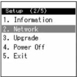 |
| 2 | Select “1. Mode.” | 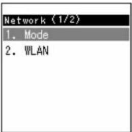 |
| 3 | You can select either manual IP or DHCP.- When selecting manual IP, refer to “3.2.1 Manual IP.”- When selecting DHCP, refer to “1.2.2 DHCP.” | 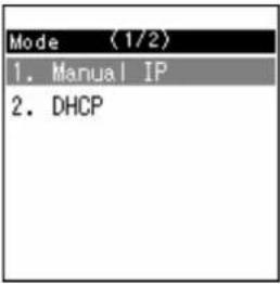 |
3.2.1 Manual IP
When using manual IP, values for the IP address, sub-network mask, and default gateway are necessary.
| 1 | Select “1. Manual IP.” | 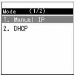 |
| 2 | The following items have been added to the “Network” menu:When using manual IP, enter these values. | 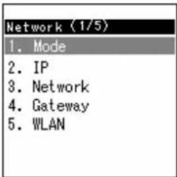 |
| 3 | Select “2. IP.” | 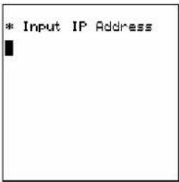 |
| 4 | Enter the IP address. Enter a period using the *Press the Key after entering the IP address. | 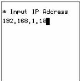 |
| 5 | Press the End key. | 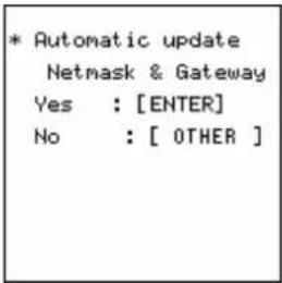 |
| 6 | Select “3. Netmask.” | 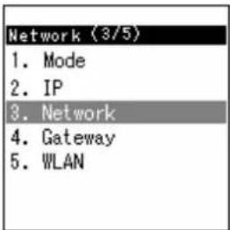 |
| 7 | Enter the netmask. Enter a period using the *Press the Key after entering the netmask. | 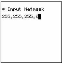 |
| 8 | Select “4. Gateway.” | 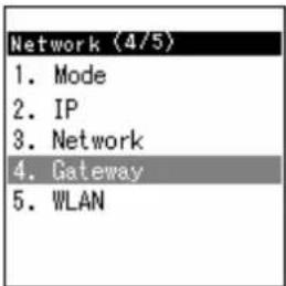 |
| 9 | Enter the gateway. Enter a period using the *Press the Key after entering the gateway. | 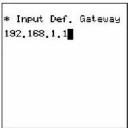 |
3.2.2 DHCP
When using DHCP, the values for the IP address, netmask, and default gateway are automatically retrieved from the DHCP server.
| 1 | Select “2. DHCP.” | Mode (2/2)1. Manual IP2. DHCP |
| 2 | A screen similar to the one to the right will appear. | DHCP Selected |
| 3 | The following items are deleted from the “Network” menu: “IP”, “Netmask”, and “Gateway”. | Network (1/2)1. Mode2. WLAN |
3.3 WLAN settings
Enter the settings for wireless LAN. When not using SSID and WEP key, go to section 1.4.
| 1 | Select “2. WLAN”. | 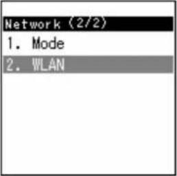 |
| 2 | - When setting SSID, refer to “3.3.1 SSID.”- When setting WEP key, refer to “3.3.2 WEP key.”Note!!!: Change the setting after reading about the various features of each Mode in “1. Mode”. While it is possible to select “Infra/Ad-hoc”, it is possible that normal operation and network connections will be negatively affected if you make mistakes with the procedure. | 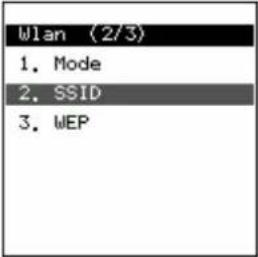 |
3.3.1 SSID
SSID is used to connect to a specific access point.
| 1 | Select “2. SSID”. | 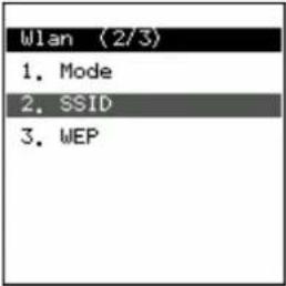 |
| 2 | Enter the SSID value for the access point you want to connect to. After entering the value, press the ☑ key. | 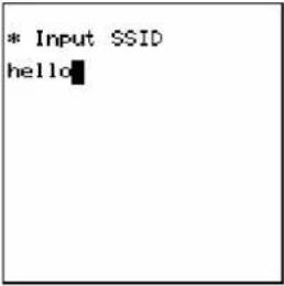 |
3.3.2 WEP key
The WEP key is used for authentication and encryption.
| 1 | Select “3. WEP”. | 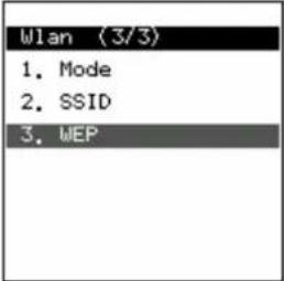 |
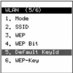
| 2 | When WEP is disabled, a screen, like the one to the right, will appear.When WEP is enabled, a screen, like the one to the right, will appear. | 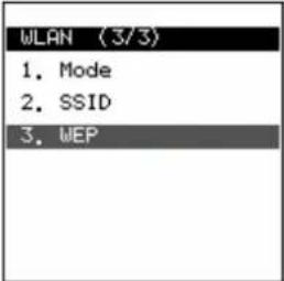 |
 | ||
| 3 | When not using WEP, select “2. WEP disable”. Proceed to the following section when after entering the settings. | 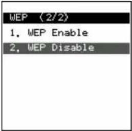 |
| 4 | When using WEP, select “1. WEP Enable”. | 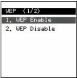 |
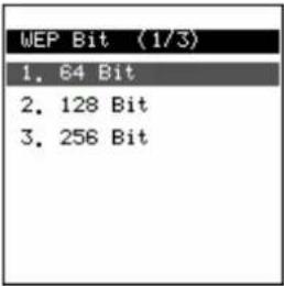
| 5 | Select “WEP Bit”.WirelessIP 5000 supports 64/128/256 bit. | 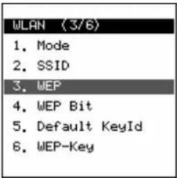 |
 | ||
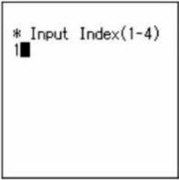
| 6 | Select “Default KeyID”, and enter the Index number. The default KeyID is connected to the WEP-Key.When the Default KeyID is set to 1, it is necessary to enter “WEP-key 1for the WEP-Key in step 8. | 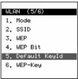 |
 | ||
| 7 | Select “6. WEP-Key”. | 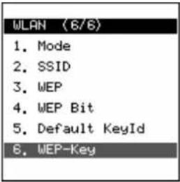 |
| 8 | Select one of the following for the “WEP-Key”: 1, 2, 3, or 4. | 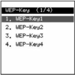 |
| 9 | Using the dial pad, enter the WEP Key. Pressing the # key enters a “:”. Note!!!: Enter the WEP Key using hexadecimal numbers. Warning!: Enter “:” after every 2 characters. | * Input WEP Key01:02:03:04:05:06 |
3.4 Boot-ROM upgrade
When upgrading the boot-ROM through a TFTP server, it is necessary to un-zip the boot-ROM folder on the TFTP server beforehand.
| 1 | Select “3. Upgrade”. | Setup (3/5)1. Information2. Network3. Upgrade4. Power Off5. Exit |
| 2 | Select “2. Boot-ROM”. | Upgrade (2/3)1. Program2. Bootrom3. Format |
| 3 | Select “1. TFTP server”. | Bootrom (1/1)1. TFTP server |
| 4 | Using the dial pad, enter the IP address for the TFTP server. (Use the * key to enter a period.) After entering the IP address, press the Key. | * Input TFTP Server 18.1.1.46 |
| If you enter an incorrect IP address for the TFTP server, a screen like the one in the figure to the right will appear. | * ERROR *Fail to download bootrom.bin | |
| 5 | After downloading, a screen, like the one to the right, will appear. Pressing the Key will write the contents into flash memory.Warning!: If the boot-ROM for WirelessIP 5000 is upgraded by an inappropriate or damaged file, it might not be possible to restore it. Upgrade after carefully checking that the TFTP settings are correct.Warning!!!: Do not turn off the power when writing the boot-ROM into flash memory. It may not be possible to restore it.If one of the above situations occurs, contact the store or dealer you purchased the product from. | * Bootrom Upgrade?Yes : [ENTER]No : [ END ]DO NOT POWER DOWN!!bootrom.bin40% |
3.5 Software upgrade
When upgrading software through the TFTP server, it is necessary to un-zip the software on the TFTP server beforehand.
| 1 | Select “3. Upgrade”. | Setup (3/5)1. Information2. Network3. Upgrade4. Power Off5. Exit |
| 2 | Select “1. Program”.Selecting “3. Format” deletes the software settings. | Upgrade (1/3)1. Program2. Bootrom3. Format |
| 3 | Select “1. TFTP server”. | Program (1/1)1. TFTP server |
| 4 | After downloading, the software will automatically start up. | Now Downloading...qstr.bin512 |
| Running... |
3.6 Closing the Boot-ROM menu
1
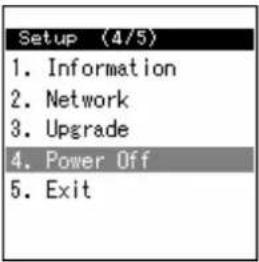
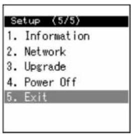
After selecting "4. Power off", the power can be turned off after closing the boot-ROM menu.
Selecting "5. Exit" closes the boot-ROM and restarts the terminal.
4. Troubleshooting
4.1 General
| Phenomena | Response |
| WirelessIP 5000 does not start. The battery is dead. If the battery is dead, WirelessIP 5000 will not start and the LED will not light up. After recharging the battery using the AC adapter, try to restart it again. | |
| A key will not work. Remove the battery, and then reconnect it. | |
| You can hardly see the screen. Adjust the contrast using the Menu>Setting>Brightness adjustment. | |
| There is a vertical line on the screen. | If it has not been used for a long time, there are cases when the line appears right after starting it up. This can also occur if the battery has been improperly removed. |
| Communication is bad, or phone suddenly disconnects. | It is possible that you are too far from the access point, the signal is being weakened by an obstruction such as a wall, or there is electromagnetic interference. Check the signal level and interference using Menu>Admin>Network>Sitescan. |
| The standby time is different to that in the specifications. | The battery standby time can be different from that noted in the specifications on account of the access point configuration or settings. Also, the standby time can be shortened due to a high or low temperature environment. |
| WirelessIP 5000 heats up. When the WirelessIP 5000 is located outside the range of the access point, there are situations when the device consumes power as when telephoning. The device can heat up slightly on account of this. The heat will not effect operation. | |
| The sound level is too low. Using the volume button, adjust the sound level. | |
| After restarting, the time reverts to the default value. | Since WirelessIP 5000 cannot maintain the time when the power is off, it is necessary to retrieve time information from the NTP server. |
| The battery becomes unusable. When the WirelessIP 5000 will not be used for more than a month please remove the battery from the handset and store it. The battery pack may become unusable due to self-discharge. Please store the battery at less than 20°C in a low-humidity environment that is clean and free of dust. | |
* When problems other than those discussed above occur, consult the store or dealer from whom you purchased the product.
Copyright© 2005
Hitachi Cable, LTD.
Otemachi Building, 6-1 Otemachi 1-chome,
Chiyoda-ku, Tokyo 100-8166, Japan
(First Edition, February 2005)
(Second Edition, July 2005)
- WirelessIP 5000 Administrator Manual (v2.0.0)
- ADMIN MENU .... 1
- Network....2
- Password 21
- Upgrade....23
- 802.1X (EAP-TLS) CERTIFICATE INSTALLATION METHODS....30
- Installation Procedures 802.1x Certificate....30
- BOOT-ROM MENU....34
- Admin menu
- Network
- 1
- Network
- Basic Info
- WLAN
- WEP
- Authentication
- TCP/IP
- SIP Outb Proxy
- NAT Traversal
- IP DiffServ
- Coder
- Jitter Buf Size
- SIP
- User Account
- Server Settings
- Outbound Proxy
- Expire
- Network Reload
- Certs Manager
- Site Scan
- Ping Test
- Manual
- 1st Proxy
- 2nd Proxy
- Password
- Admin Password
- User Pwd Reset
- Upgrade
- Program
- Configuration
- Setup
- TFTP server
- Auto Upgrade
- 2
- Syslog
- 3
- Web Server
- Phone Reset
- Statistics
- 802.1x (EAP-TLS) Certificate Installation Methods
- Installation Procedures 802.1x Certificate
- Root Certificate
- Private Certificate
- Boot-ROM menu
- Opening the boot-ROM menu
- Network settings
- Manual IP
- DHCP
- WLAN settings
- SSID
- WEP key
- Boot-ROM upgrade
- Software upgrade
- Closing the Boot-ROM menu
- Troubleshooting
- General
Brand : HITACHI
Model : IP5000
Category : Phone