
HDS-WHDI100 - AV Extender Peerless-AV - Free user manual and instructions
Find the device manual for free HDS-WHDI100 Peerless-AV in PDF.


| Product Type | Wireless HD Multimedia System (Extender) |
| Brand | Peerless-AV |
| Model | HDS-WHDI100 |
| Transmitter Dimensions (W x L x H) | 7.17 x 3.80 x 1.24 in (182 x 96.5 x 31.5 mm) |
| Receiver Dimensions (W x L x H) | 3.74 x 3.74 x 1.28 in (95 x 95 x 32.2 mm) |
| Power Supply | 100-240V AC input, 5V DC output (included adapters) |
| Supported Video Resolutions | 1080p, 1080i, 720p, 480p, 576p, 3D formats (frame packing, top-and-bottom, side-by-side) |
| Supported Audio | PCM, AC3, DTS; up to 5.1 digital audio; 2-channel PCM up to 24-bit/96kHz |
| Transmission Distance | Up to 100 ft (30m) line of sight; up to 30 ft (9m) through one structure |
| Wireless Frequency | 4.9-5.9 GHz (auto-adjusting) |
| Latency | Zero latency (<1ms) |
| Antenna | Omnidirectional (internal) |
| HDMI Inputs (Transmitter) | 2 x Type A |
| HDMI Outputs | Transmitter: 1 x Type A (pass-through); Receiver: 1 x Type A |
| IR Control | IR sensor on both units; IR flasher on transmitter for remote control of source devices |
| USB HID Support | Yes (SERVICE port on transmitter, USB port on receiver for keyboard/mouse/game controller) |
| Remote Control | Included (requires 2 AAA batteries) |
| Package Contents | Transmitter, Receiver, Remote Control, 2 Power Adapters, IR Flasher, Mounting Screws & Anchors, User Manual |
| Operating Temperature | 32°F – 104°F (0°C – 40°C) |
| Storage Temperature | 14°F – 131°F (-10°C – 55°C) |
| Relative Humidity | 10% – 80% |
| Safety Certifications | FCC Part 15, Industry Canada (ICES-003) |
| Warranty | 1 year from original purchase date (proof of purchase required) |
| Maintenance | Clean with a soft, dry cloth only. Do not use water or cleaning products. |
| Spare Parts / Reparability | No user-serviceable parts inside. Refer servicing to qualified personnel. |
Frequently Asked Questions - HDS-WHDI100 Peerless-AV
User questions about HDS-WHDI100 Peerless-AV
0 question about this device. Answer the ones you know or ask your own.
Ask a new question about this device
Download the instructions for your AV Extender in PDF format for free! Find your manual HDS-WHDI100 - Peerless-AV and take your electronic device back in hand. On this page are published all the documents necessary for the use of your device. HDS-WHDI100 by Peerless-AV.
USER MANUAL HDS-WHDI100 Peerless-AV
User Manual and Installation Guide
peerAir™
WIRELESS HD
MULTIMEDIA SYSTEM

Models:
HDS-WHDI100

HDMI

peerless-AV®
Contents
Safety Precautions ....3
Important Information 4
Unit Care Recommendations ....4
Introduction......5
Package Contents 5
Component Specifications....6
Transmitter 6
Receiver 7
Remote Control 8
Installation and Operation 9
Installing the Remote Control Batteries....9
Wall Mounting the HDS-WHDI100 (Optional)....10
Transmitter Setup....11
Receiver Setup....12
IR Flasher Setup ....14
System Operation....13
Checking IR Flasher Frequency....15
Changing IR Flasher Frequency ....15
Indicator Lights Decoded....16
On Screen Display (OSD) Functions....17
Troubleshooting....19
Appendix 21
Supported Resolution....21
Audio Bit Rate Support....22
Product Specifications....23
FCC Statement....24
Industry Canada Statement......25
Warranty 26
Contact Information 27
WARNING!
RISK OF ELECTRICAL SHOCK DO NOT OPEN

WARNING: TO REDUCE THE RISK OF ELECTRICAL SHOCK DO NOT REMOVE THE COVER. NO USER-SERVICEABLE PARTS ARE INSIDE. REFER SERVICING TO QUALIFIED PERSONNEL
- Power to the units must be switched off before any work is undertaken, such as any AV device connection or TV connection.
- To prevent electric shock, make sure to use the supplied DC adapters as power supply to the Transmitter and Receiver.
- Be sure the power cord is routed so that it will not be stepped on or pinched by heavy items.
- Avoid overloading electrical outlets or extension cords which otherwise could result in electric shock or fire.
- Disconnect the product from the power source if it is left unattended for an extended period of time, and to protect the product from lightning.
- To reduce the risk of electric shocks or fire, always disconnect the power cord from the power outlet when you are not using your HDS-WHDI100 for an extended period of time.
- This product should not be exposed to dripping or splashing liquids. No object filled with liquids, such as vases, should be placed on the product.
- To avoid electric shock, never stick anything in the slots on the case or remove the cover.
- Place Transmitter and Receiver on a flat, hard and stable surface.
- Do not block the ventilation slots on the Transmitter or Receiver or place any heavy object on the top cover. Blocking the airflow could damage the Transmitter or Receiver. Arrange components so that air can flow freely around the Transmitter and Receiver. Ensure that there is adequate ventilation if the Transmitter and/or Receiver is placed in a cabinet. Put the Transmitter and Receiver in a properly ventilated area, away from direct sunlight or any source of heat.
- To reduce the risk of fire or electric shock, do not expose the Transmitter and/or Receiver to water or moisture.
- This product is intended for indoor use only.
Important Information
- Never use this product in an aircraft or a medical facility as it can cause interference or an undesirable effect.
- The use of this product in the following locations may result in abnormal video and audio output (noise, blocked image... etc,).
° When the product is placed near a refrigerator or metal structure.
° A cluttered room where the wireless signals may be blocked.
- This product has been tested and manufactured to comply with each country's safety rules. However, there is no guarantee that interference will not occur in some installations. If interference happens, decrease the distance between the Transmitter and Receiver.
- This product may interfere with 5GHz wireless devices.
- Optimal use of this product is for in-room/multi-room applications with a range of up to 100 ft. (30m) away line of sight, up to 30ft (9m) through one structure.
- Any changes or modifications not expressly approved by the manufacturer of this device could void the product warranty.
- This equipment must be installed and operated in accordance with the provided instructions. The Transmitter must be installed to provide a separation distance of at least 8" (20cm) from all persons and must not be operating near or in conjunction with any other Transmitter. End users and installers must be provided with installation instructions and Transmitter operating conditions for satisfying RF exposure compliance.
- This device should be used only as specified within this manual to meet RF exposure requirements. Use of this device in a manner inconsistent with this manual could lead to excessive RF exposure conditions.
Unit Care Recommendations
To clean, use a soft, dry cloth only. Do not use water or other cleaning products as they may cause electrical failure or damage the surface of the product.
Introduction
The PeerAir™ Wireless HD Multimedia System delivers uncompressed Full HD 1080p, as well as all 3D, contents to your existing HDTV set wirelessly. This system operates in the 5GHz RF band, and has the ability to adjust its communication frequencies automatically, reducing interference from other RF devices. With built-in omnidirectional antennas, this system transmits uncompressed content up to 100 ft. (30m) away line of sight, up to 30ft (9m) through one structure with zero latency (<1ms).
Package Contents
Ensure that the following items are present in the package. If any items are missing or damaged, please call Peerless-AV Customer Care at 1-800-865-2112. (available 7:00am - 7:00pm (CST) Monday - Friday).

Component Specifications
Transmitter
Transmitter Top

1. Power Button
- Press to turn the Transmitter ON/OFF. The indicator light in the power button will be illuminated blue when the power is on, and turns red in standby mode.
2. SOURCE Selection Button
- Press to toggle AV device inputs.
3. Source Indicator Lights
- The source indicator lights will be illuminated to show current input selected.
Transmitter Back

1. DC 5V
- DC power input port.
2. HDMI 1
- HDMI 1 input port.
3. HDMI 2
- HDMI 2 input port.
4. HDMI OUT
• HDMI pass-through output port.
5. IR OUT
- Connects IR Flasher to the Transmitter for remote control of AV devices which are connected to the Transmitter (i.e. Blu-ray player, DVD, STB, etc).
6. SERVICE
• Supports remote usage of USB HID peripheral, such as gaming controller, mouse or keyboard.
Receiver
Receiver Top
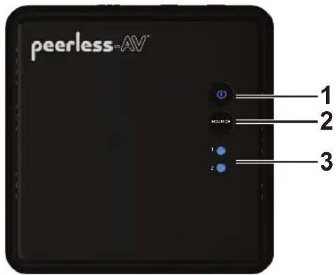
1. Power Button
- Press to turn the Receiver ON/OFF. The indicator light will be illuminated blue when the power is on, and turns red in standby mode.
2. SOURCE Selection Button
- Press to toggle AV device inputs.
3. Source Indicator Lights
- The source indicator lights will be illuminated to show current input selected.
Receiver Back

1. Mini USB DC IN
- DC power input port.
2. USB HID Port
• Supports remote usage of USB HID peripheral, such as gaming controller, mouse or keyboard
3. HDMI OUT
- HDMI output port.
Remote Control

1. POWER Button
• Turns the Transmitter and Receiver power ON/OFF.
2. INFO Button
- Press to display OSD (On Screen Display) for system related information on HDTV connected to the Receiver.
3. IR Button
- Press to change the IR Flasher frequency to meet the AV device's requirement.
4. SOURCE Button
- Press to toggle between AV devices connected to the Transmitter.
5. TRANSMITTER NO. Button
- Press to select the transmitter selection menu, and allows access to SETUP menu for pairing, removing and renaming a Transmitter.
6. Navigation Buttons
• Use the up, down, left or right buttons to navigate through the menus and select menu items.
7. OK Button
- Press the OK button to execute the selection navigated to by using the NAVIGATION buttons.
Installation and Operation
Installing the Remote Control Batteries
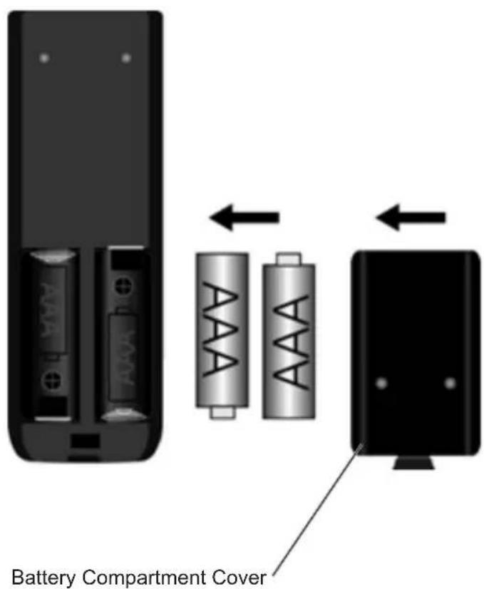
Remove the battery compartment cover. Place two AAA batteries (included) into the remote control as shown. Replace the battery compartment cover.
Wall Mounting the HDS-WHDI100 (Optional)
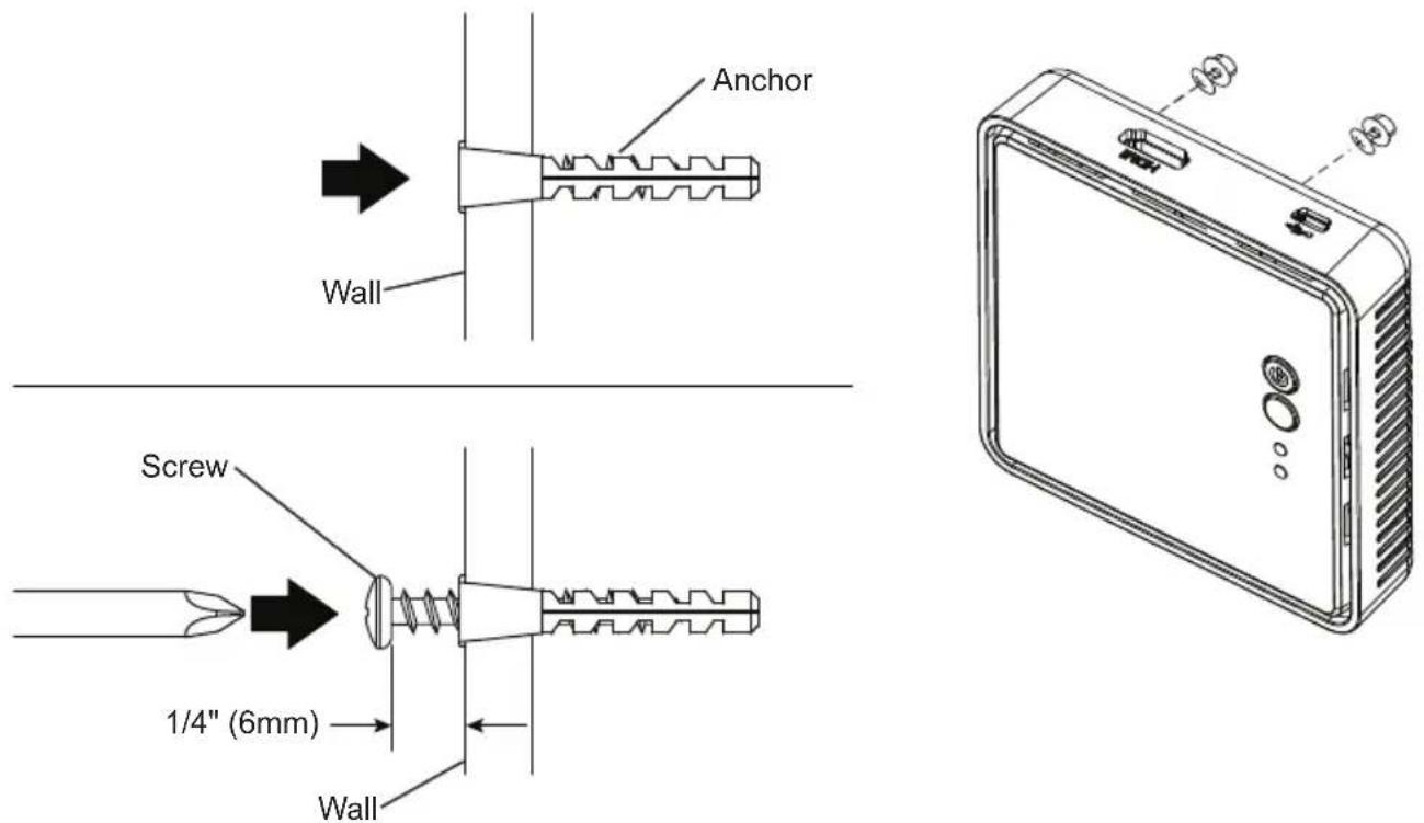
Both the Transmitter and Receiver can be mounted to a wall using the keyhole mounting slots located on the back of each unit.
Note: Wall mounting the Transmitter and/or Receiver will reduce IR functionality.
Step 1
Transfer the dimensions shown below to the desired mounting location on the wall and mark with a pencil.

Receiver
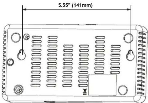
Transmitter
Step 2
Using the marks as a guide, drill two 7/32" (5mm) holes. Insert the supplied anchors into the holes. Using a screwdriver, install the mounting screws into the anchors, leaving 1/4" (6mm) of space between the head of the screw and the wall. Place the Transmitter and/or Reveiver over the screws and slide down into position.
Transmitter Setup
Step 1
A. Connect HDMI cable (not included) from AV device's HDMI out port to Transmitter's HDMI 1 port. Repeat for HDMI 2 port if a second AV device is to be connected.
B. (Optional) If connecting to HDTV using wired connection, plug HDMI cable (not included) from Transmitter's HDMI OUT port to HDTV's HDMI in port.
C. (Optional) If connecting to PC for remote usage of USB HID peripheral, such as gaming controller, mouse or keyboard, plug mini USB-to-USB Type A cable (not included) from Transmitter's SERVICE port to PC's USB OUT port.
D. Plug DC Power Adapter into power outlet.
![graph TD A["HD Media Player"] -->|A| B["Blu-ray Player"] A -->|B| C["HDTV"] A -->|C| D["PC"] B -->|D| E["DC 5V"] B -->|E| F["HD MI 1 HDMI 2"] B -->|E| G["IR OUT"] B -->|E| H["SERVICE"] C --> I["PC"] style A fill:#f9f,stroke:#333 style B fill:#ccf,stroke:#333 style C fill:#cfc,stroke:#333 style D fil…](/content/2026/05/921943/images/75742f8f09e29244b3e14f22d7443dee4d564f2ae5a91da46f3ac059cd21642b.jpg)
Receiver Setup
Step 2
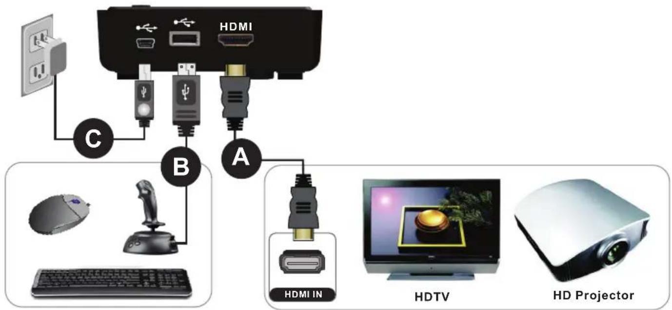
A. Connect HDMI cable from Receiver's HDMI OUT port to HDTV's HDMI in port.
B. (Optional) If using a USB HID peripheral such as a game controller, mouse or keyboard, plug into Receiver's USB port.
C. Plug mini USB power adapter into a power outlet.
IR Flasher Setup
Step 3
Connect the IR Flasher into the IR OUT port of the Transmitter. Find the IR window on the AV device and adhere the IR Flasher eye on top of the IR window.
When the IR Flasher is connected, up to three AV devices can be controlled from Receiver location.

System Operation
Step 1
If the Transmitter and Receiver are in Standby mode (both Power indicator lights of Transmitter and Receiver are lit in red), power on the display that you would like to view content on. If the display that is powered on is connected to the receiver it will take the system out of standby mode and content will begin streaming. If the display that is powered on is connected to the HDMI out port on the transmitter, content will be displayed on the local TV, but it will not take the system out of standby mode.
Note: The HDMI OUT pass through port is always on even if the Transmitter is in standby mode.

During boot-up, the Power indicator light will blink blue until the signal link between the Transmitter and Receiver is established, between 15 - 20 seconds.

Step 2
Check that your output device is turned on and set to the proper HDMI input.
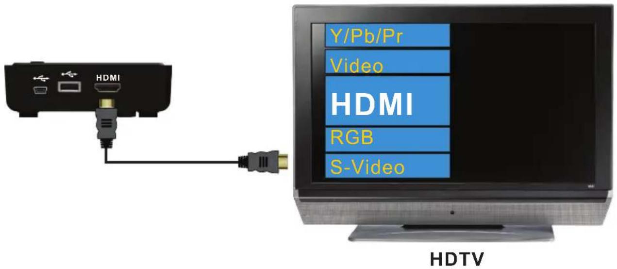
Press the SOURCE button on the remote control, or on the top of Transmitter or Receiver, to select the desired AV device input.


If all operation is normal, the Power and SOURCE indicator lights will be illuminated blue. Refer to the table containing detailed indicator light and OSD description of Transmitter/Receiver.
Checking IR Flasher Frequency
Step 1
Using the remote control for your AV device, point the remote control at the Receiver and press the Power button. If the power on the AV device turns ON/OFF, the remote frequency is set for the AV device.
If the power on the AV device does not turn ON/OFF, the remote frequency needs to be changed. Go to step 2a.
Changing IR Flasher Frequency
Step 2a
Using the remote provided with this system, press the IR button once to display the active IR Flasher frequency. Press the IR button again to change to the next frequency. The IR Flasher frequency will change with each button press.
Step 2b
After changing to the next frequency, press the Power button on your AV device's remote control. If the AV device turns ON/OFF, the remote frequency is set.
If there is no action from your AV device, use the remote provided with this system to change to the next frequency and repeat the above steps until a proper IR frequency is located.
Notes:
• One IR Flasher eye is to be used for one component device.
- The IR sensor supports 35KHz - 58KHz carrier frequencies. Therefore, it is possible that some devices may not be supported.
- Most often, the IR window is easier to locate with direct light shining on sections of the front panel of your AV device (a small flashlight works well).
Indicator Lights Decoded
| Power Indicator Light | Source Indicator Light | OSD Display (Receiver) | Description | |
 | Power saving mode.Solid R | |||
| Blinking Blue Blinking |  Full strength Full strength | Transmitter and Receiver start up times are between 15 to 20 seconds. | ||
| BlinkingBlinking Blue | 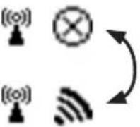 These icons will be looping when the on-screen display is activated by pressing the INFO button on the remote control. These icons will be looping when the on-screen display is activated by pressing the INFO button on the remote control. | During warm-up, if link is not established after 80 seconds, see Notes below. | ||
| Solid Blue | Blinking(Quickly) | 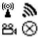 | No input from selected source(see Notes below) | |
| Solid Blue | Blinking(Slowly) |  | Video format not recognized(see Notes below) | |
| Solid Blue Solid Blue | - Video format is recognized | |||
Notes:
- If wireless connection is not established after 80 seconds, the Transmitter is out of range. Verify that the range between the Transmitter and Receiver is within specifications and adjust or shorten the distance between your Transmitter and Receiver. The maximum transmission range for 1080p content is up to 100 ft. (30m) line of sight and 30 ft. (9m) through one structure. The ideal minimum range is 6.5 ft. (2m).
- Ensure that the source device is powered on and the Transmitter is set to the proper input.
- If there is no video showing on the output device and the on screen display states "Not Supported Format", this is an indication that the video frame rate from the AV device is not supported. Refer to the Supported Resolutions section of the Appendix.
• Each Transmitter and Receiver should ideally be at least 6.5 ft. (2m) away from one another. - If running multiple systems make sure that transmitters are separated by at least 6.5 ft. (2m).
- Proper Shutdown Procedure - To turn the system off simply turn off the display that you were viewing and the system will automatically go into standby within 5 minutes. Powering the system down by using the power button on the transmitter can cause the transmitter and receiver to lose their sync. If this occurs, connection can be re-established by power cycling the receiver.
- CEC/ HDMI Control - The HDS-WHDI100 does not support CEC/HDMI Control. Please ensure that CEC/HDMI Control is disabled on all connected source equipment and displays. Instructions for this process can be found in the User Manuals for the connected devices.
On Screen Display (OSD) Functions
By pressing the INFO button on the Remote Control, the OSD will display signal quality, source, channel and resolution. Pressing the INFO button again will exit the screen.
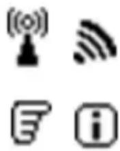
HDMI1 CH1\~9 1280x1024
=OFF
Pressing the SOURCE button on the Remote Control, or directly on the Transmitter or Receiver, enables selection between input sources.

HDMI1 CH1\~9 1280x1024
OR
HDMI2 CH1\~9 1280x1024
Pressing the IR button on the Remote Control displays the current IR frequency status. Pressing the IR button a second time changes the IR frequency. (Default IR frequency is set to 47KHz.)
Press IR button to display current IR frequency:
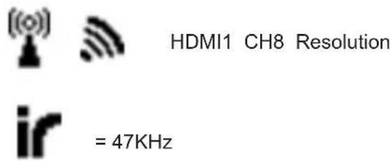
Press IR button again to change current IR frequency:

Note: Only the status of the Receiver connected to the HDTV can be displayed on the OSD. The status of the Transmitter's HDMI OUT pass-through cannot be displayed.
Troubleshooting
| Problem Solution | |
| The power indicator light does not light up. | Check the power connections on the Transmitter and Receiver to ensure they are properly inserted into a functioning power outlet. |
| No video is displayedon your TV screen. | Verify that the proper cables have been selected and installed between the Transmitter input and your AV device output.On the TV side (connected to the Receiver), select the HDMI port that the receiver is connected to as the input source.Verify the state of the Power and Source as indicated below:Power Indicator Light Flashing Blue OSD displayed:  Ensure the transmission range between the Transmitter and Receiver is NOT over 100 ft. (30m) line of sight (LOS) and 30 ft. (9m) through one structure.Move the Transmitter closer to the Receiver.Power Indicator Light Solid Blue + Slow Flashing SOURCE Indicator Light OSD displayed : Ensure the transmission range between the Transmitter and Receiver is NOT over 100 ft. (30m) line of sight (LOS) and 30 ft. (9m) through one structure.Move the Transmitter closer to the Receiver.Power Indicator Light Solid Blue + Slow Flashing SOURCE Indicator Light OSD displayed :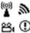 Ensure your video resolution and frame rate is supported and within the transmission range.Connect the AV device to your TV to check and modify the video format compatibility.Check that the resolution of your device is set to 1080p, 1080i, 720p,or 480p. Refer to the Supported Resolution section of the appendixPower Indicator Light Solid Blue + Fast Flashing SOURCE Light OSD displayed : Ensure your video resolution and frame rate is supported and within the transmission range.Connect the AV device to your TV to check and modify the video format compatibility.Check that the resolution of your device is set to 1080p, 1080i, 720p,or 480p. Refer to the Supported Resolution section of the appendixPower Indicator Light Solid Blue + Fast Flashing SOURCE Light OSD displayed :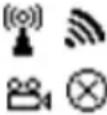 Ensure the proper cables are connected between the Transmitter and your AV devices.Ensure your AV devices connected to the Transmitter are powered on.Ensure the proper cables are connected between the Receiver and your HDTV.Power indicator light on receiver slow flashing purple + no source light OSD displayed:Unplug the power from the transmitter and receiver. Press and hold the power button down on the receiver and plug the power back into the receiver, while continuing to hold the power button down. Release the power button when the power light on the receiver turns from blue to purple. Press and hold the power button on the transmitter. Plug the power back into the transmitter while continuing to hold the power button on the transmitter down. Do not release the power button on the transmitter until you see the power light change from blue to purple. You will see "Adding WHD200" on the screen with a progress bar beneath it. Once the process is complete the system should connect and resume video streaming. Ensure the proper cables are connected between the Transmitter and your AV devices.Ensure your AV devices connected to the Transmitter are powered on.Ensure the proper cables are connected between the Receiver and your HDTV.Power indicator light on receiver slow flashing purple + no source light OSD displayed:Unplug the power from the transmitter and receiver. Press and hold the power button down on the receiver and plug the power back into the receiver, while continuing to hold the power button down. Release the power button when the power light on the receiver turns from blue to purple. Press and hold the power button on the transmitter. Plug the power back into the transmitter while continuing to hold the power button on the transmitter down. Do not release the power button on the transmitter until you see the power light change from blue to purple. You will see "Adding WHD200" on the screen with a progress bar beneath it. Once the process is complete the system should connect and resume video streaming. |
Troubleshooting
| Problem Solution | |
| Poor picture quality or intermittent video. | Check that the resolution of your device is set to 1080p, 1080i, 720p, 576p, or 480p.Please refer to the Supported Resolution section of the Appendix.Ensure the transmission distance is less than 100 ft. (30m) line of sight (LOS) and 30 ft. (9m) through one structure. |
| No audio • Check your HDTV's volume is properly set and not set in "MUTE" mode.Check if your AV device's audio volume has been turned up.Ensure the audio bit rate of the AV device can be supported. Refer to the Audio Bit Rate Support section of the Appendix. | |
| IR flasher can't control AV device. | Check the location and position of the IR Flasher on the AV device. Refer to IR Flasher Set Up in the Setup and Operation section of this manual.Change the IR Flasher frequency to meet the AV device's requirement. Refer to On Screen Display (OSD) Functions in the Setup and Operation section of this manual. |
| No 3D video output | OSD displayed : Transmitter  and/or Receiver and/or Receiver  Check that both TVs support 3D video format. If either TV only supports 2D format, then 3D output will not be supported.If displaying 3D video on the HDTV which supports 3D video, turn off the 2D HDTV and cycle the power on 3D HDTV (turn OFF, then ON). Set the AV player to 3D video format output for the 3D display.Check that the 3D AV device is set to 24p. Check that both TVs support 3D video format. If either TV only supports 2D format, then 3D output will not be supported.If displaying 3D video on the HDTV which supports 3D video, turn off the 2D HDTV and cycle the power on 3D HDTV (turn OFF, then ON). Set the AV player to 3D video format output for the 3D display.Check that the 3D AV device is set to 24p. |
Supported Resolution
If the SOURCE indicator light continues to blink blue (slower than “no signal” mode); OSD display: 🚗, and there is no video displayed or the video quality is poor, it may indicate that the video frame rate from your AV device is not supported. Ensure that the timing of the AV device is compliant with the standards listed below:
| 2D Video Format Timings Resolution Support | ||
| Primary CEA Video Timing | ||
| 640x480p @ 60Hz YES | 480p | |
| 720x480p @ 60Hz YES | ||
| 720x576p @ 50Hz 576p YES | ||
| 1280x720p @ 50Hz YES | 720p | |
| 1280x720p @ 60Hz YES | ||
| 1920x1080i @ 50Hz YES | 1080i | |
| 1920x1080i @ 60Hz YES | ||
| 1920x1080p @ 50Hz YES | 1080p / 60 | |
| 1920x1080p @ 60Hz YES | ||
| Secondary CEA Video Timing | ||
| 1920x1080p @ 24Hz YES | 1080p / 24 | |
| 1920x1080p @ 25Hz YES | ||
| 1920x1080p @ 30Hz YES | ||
| VESA Timing (DVI only) | ||
| 640x480 @ 60 / 72.809Hz VGA YES | ||
| 800x600 @ 60 / 72.188Hz SVGA YES | ||
| 1024x768 @ 60 / 70.069Hz XGA YES | ||
| 1280x768 @ 60 Hz WXGA | YES | |
| 1280x1024 @ 60 Hz | SXGA YES | |
| Mandatory CEA 3D Video Format Timings | Support |
| 1280x720p @ 50Hz Top-and-Bottom | YES |
| 1280x720p @ 50Hz Frame packing | YES |
| 1280x720p @ 60Hz Top-and-Bottom | YES |
| 1280x720p @ 60Hz Frame packing | YES |
| 1920x1080i @ 50Hz Side-by-Side (Half) | YES |
| 1920x1080i @ 60Hz Side-by-Side (Half) | YES |
| 1920x1080p @ 24Hz Top-and-Bottom | YES |
| 1920x1080p @ 24Hz Frame packing | YES |
Audio Bit Rate Support
- Digital audio from HDMI inputs: Up to 6Mbit/s bit-rate support.
• Supports 5.1 digital audio.
• 2-channel PCM: 16 - 24 bits audio sampling with 32 - 96KHz sampling rate as below:
| 2 Channel PCM | 32KHz | 44.1KHz | 48KHz | 96KHz |
| 16 bits YES | YES | YES | YES | |
| 24 bits YES | YES | YES | YES |
Product Specifications
| HDS-WHDI100 | |||
| Supported Video Resolutions | HDMI Input | 1080p, 1080i, 720p, 480p | |
| Supported Audio Resolutions | Digital Audio | PCM, AC3 and DTS | |
| Transmission Distance | Up to 100 feet line of sight (up to 30ft (9m) through one structure). | ||
| Antenna | Omnidirectional (internal) | ||
| Latency | Zero Latency (<1ms) | ||
| Operating Frequencies | 4.9-5.9 GHz (Includes non-DFS frequency bands) | ||
| Power Supply | 100-240V AC in, 5V DC power adapter | ||
| Operating Temperature | 32°F -104°F (0°C - 40°C) | ||
| Operating Relative Humidity | 10% - 80% | ||
| Storage Temperature | 14°F - 131°F (-10 °C - 55°C) | ||
| Interface Transmitter Receiver | |||
| AV HDMI Input | 2 x Type A N/A | ||
| Interface HDMI Output | 1 x Type A 1 x Type A | ||
| IR Control | IR Sensor | Yes Yes | |
| IR Flasher | Yes No | ||
| Power Interface Power Input | 5V DC 5V mini USB | ||
| Buttons | Power Button | Yes (1 x tact switch) Yes (1 x tact switch) | |
| Source Button | Yes (1 x tact switch) Yes (1 x tact switch) | ||
| LEDs | Power LED | 1 X LED (two tone: Blue/Red) 1 X LED (two tone: Blue/Red) | |
| Source LED | 2 x LED (Blue) 2 x LED (Blue) | ||
| Dimensions (W) x (L) x (H) | 7.17" x 3.80" x 1.24" (182 x 96.5 x 31.5mm) 3.74" x 3.74" 1.28" (95 x 95 x 32.2mm) | ||
* Transmission distance will depend on actual environment. Distance based on line-of-sight. Structures constructed of steel, wood, concrete, or/and brick may decrease transmission distance.
Federal Communication Commission Interference Statement
This device complies with Part 15 of the FCC Rules. Operation is subject to the following two conditions: (1) This device may not cause harmful interference, and (2) this device must accept any interference received, including interference that may cause undesired operation.
This equipment has been tested and found to comply with the limits for a Class B digital device, pursuant to Part 15 of the FCC Rules.
These limits are designed to provide reasonable protection against harmful interference in a residential installation. This equipment generates, uses and can radiate radio frequency energy and, if not installed and used in accordance with the instructions, may cause harmful interference to radio communications. However, there is no guarantee that interference will not occur in a particular installation.
If this equipment does cause harmful interference to radio or television reception, which can be determined by turning the equipment off and on, the user is encouraged to try to correct the interference by one of the following measures:
- Reorient or relocate the receiving antenna.
- Increase the separation between the equipment and receiver.
- Connect the equipment into an outlet on a circuit different from that to which the receiver is connected.
- Consult the dealer or an experienced radio/TV technician for help
FCC Caution:
Any changes or modifications not expressly approved by the party responsible for compliance could void the user's authority to operate this equipment.
This transmitter must not be co-located or operating in conjunction with any other antenna or transmitter
Radiation Exposure Statement (Transmitter):
This equipment complies with FCC radiation exposure limits set forth for an uncontrolled environment. This equipment should be installed and operated with minimum distance 20cm between the radiator & your body.
Radiation Exposure Statement (Receiver):
This equipment complies with FCC radiation exposure limits set forth for an uncontrolled environment. This equipment should be installed and operated with minimum distance 20cm between the radiator & your body
Note: The country code selection is for non-US model only and is not available to all US model. Per FCC regulation, all WiFi product marketed in US must fixed to US operation channels only
Industry Canada Statement
Caution: (i) the device for operation in the band 5150-5250 MHz is only for indoor use to reduce the potential for harmful interference to co-channel mobile satellite systems;
(ii) the maximum antenna gain permitted for devices in the bands 5250-5350 MHz and 5470-5725 MHz shall be such that the equipment still complies with the e.i.r.p. limit;
(iii) the maximum antenna gain permitted for devices in the band 5725-5850 MHz shall be such that the equipment still complies with the e.i.r.p. limits specified for point-to-point and non-point-to-point operation as appropriate; and
(iv) Users should also be advised that high-power radars are allocated as primary users (i.e. priority users) of the bands 5250-5350 MHz and 5650-5850 MHz and that these radars could cause interference and/or damage to LE-LAN devices.
Radiation Exposure Statement: This equipment complies with ISED radiation exposure limits set forth for an uncontrolled environment. This equipment should be installed and operated with minimum distance 20cm between the radiator & your body.
The Product is warranted to be free from defects in material and workmanship, given normal use and care, for 1 Year from the original purchase date with proof of purchase. Please retain a copy of your receipt as you will need this to obtain warranty work. We will repair or replace the product which fails as a result of such a defect during the warranty period. The accessories are not covered by this warranty.
This warranty is the customers' exclusive remedy for product defect and does not apply to:
- Any modifications made to the product in any way by the consumer
- Attachments to the product by the consumer that causes product damage
- Any product which the seals/and or serial numbers and/or logos have been broken, removed, or tampered with, defaced, or altered in any manner
- Damage caused by abuse, misuse, accident, water, or theft
- Physical damage
- Loss of the Accessories
Except as stated above, Peerless Industries, Inc. makes no express or implied warranties as to any product, in Particular, makes no warranty of merchantability or fitness for any particular purpose. Peerless Industries, Inc. shall not be liable for consequential or incidental damages arising from any product defect. Our liability is limited to replacement of any defective product as stipulated under the warranty conditions. Peerless Industries, Inc. expressly disclaims all warranties not satisfied in this limited warranty. Any implied warranties that may be imposed by law are limited to the terms of this limited warranty.
Customer Care
Need help with set up? Call Peerless-AV Customer Care
1-800-865-2112 (available 7:00am- 7:00pm CST, Monday - Friday), or email us at info@peerless-av.com.
Peerless -AV
2300 White Oak Circle
Aurora, IL 60502 USA
peerair.peerless-av.com

Peerless -AV
2300 White Oak Circle
Aurora, IL 60502 USA
peerair.peerless-av.com
©2016 Peerless-AV. All rights reserved. Peerless-AV is a trademark of Peerless Industries, Inc. Other parties' marks are the property of their respective owners.
- USER MANUAL AND INSTALLATION GUIDE
- WIRELESS HD
- MULTIMEDIA SYSTEM
- CONTENTS
- WARNING
- IMPORTANT INFORMATION
- UNIT CARE RECOMMENDATIONS
- INTRODUCTION
- PACKAGE CONTENTS
- COMPONENT SPECIFICATIONS
- TRANSMITTER
- TRANSMITTER TOP
- POWER BUTTON
- SOURCE SELECTION BUTTON
- SOURCE INDICATOR LIGHTS
- TRANSMITTER BACK
- DC 5V
- HDMI 1
- HDMI 2
- HDMI OUT
- IR OUT
- SERVICE
- RECEIVER
- RECEIVER TOP
- RECEIVER BACK
- MINI USB DC IN
- USB HID PORT
- REMOTE CONTROL
- INFO BUTTON
- IR BUTTON
- SOURCE BUTTON
- TRANSMITTER NO. BUTTON
- NAVIGATION BUTTONS
- OK BUTTON
- INSTALLATION AND OPERATION
- INSTALLING THE REMOTE CONTROL BATTERIES
- WALL MOUNTING THE HDS-WHDI100 (OPTIONAL)
- STEP 1
- STEP 2
- TRANSMITTER SETUP
- RECEIVER SETUP
- IR FLASHER SETUP
- STEP 3
- SYSTEM OPERATION
- CHECKING IR FLASHER FREQUENCY
- CHANGING IR FLASHER FREQUENCY
- STEP 2A
- STEP 2B
- NOTES
- ON SCREEN DISPLAY (OSD) FUNCTIONS
- TROUBLESHOOTING
- SUPPORTED RESOLUTION
- AUDIO BIT RATE SUPPORT
- PRODUCT SPECIFICATIONS
- FEDERAL COMMUNICATION COMMISSION INTERFERENCE STATEMENT
- FCC CAUTION
- RADIATION EXPOSURE STATEMENT (TRANSMITTER)
- RADIATION EXPOSURE STATEMENT (RECEIVER)
- INDUSTRY CANADA STATEMENT
- THIS WARRANTY IS THE CUSTOMERS' EXCLUSIVE REMEDY FOR PRODUCT DEFECT AND DOES NOT APPLY TO
- CUSTOMER CARE
Brand : Peerless-AV
Model : HDS-WHDI100
Category : AV Extender