GF-1912 - Fingerprint Reader Geovision - Free user manual and instructions
Find the device manual for free GF-1912 Geovision in PDF.


| Product Type | Fingerprint Reader |
| Model | GV-GF1912 |
| Brand | Geovision |
| Dimensions (H x W x D) | 130 x 54 x 38 mm (5.12 x 2.13 x 1.50 in) |
| Weight | 160 g (0.35 lb) |
| Power Supply | DC 7.5V ~ 12V, Max 250mA |
| Sensor Type | Optical |
| Sensing Area | 20 x 17 mm (0.79 x 0.67 in) |
| Communication Interfaces | Wiegand 26, RS-485, TCP/IP (LAN) |
| Operation Modes | Fingerprint Only, Card + Fingerprint, Card Only |
| Fingerprint Storage Capacity | 1,900 fingerprints (Fingerprint Only mode) |
| Supported Cards | ISO14443A (MIFARE DESFire, MIFARE Plus, MIFARE Classic), 13.56 MHz |
| Operating Temperature | 0 ~ 50°C (32 ~ 122°F) |
| Humidity | 10% ~ 90% |
| Certification | CE, FCC |
| Application | Indoor use only |
| Regular Maintenance | Regular cleaning recommended to maintain good working condition |
| Security Features | Anti-duress fingerprint, access scheduling |
| Included Accessories | Fingerprint reader, Manager Enroll Card, Manager Delete Card, mounting plate, screws, security screw, Torx wrench, connector wire, software CD |
Frequently Asked Questions - GF-1912 Geovision
User questions about GF-1912 Geovision
0 question about this device. Answer the ones you know or ask your own.
Ask a new question about this device
Download the instructions for your Fingerprint Reader in PDF format for free! Find your manual GF-1912 - Geovision and take your electronic device back in hand. On this page are published all the documents necessary for the use of your device. GF-1912 by Geovision.
USER MANUAL GF-1912 Geovision
GV-GF Fingerprint Reader
User's Manual
natural_image
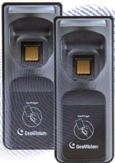
Two identical black rectangular devices with 'GeoVision' branding, each displaying a small square component (no text or symbols on the device itself)Before attempting to connect or operate this product, please read these instructions carefully and save this manual for future use.

GeoVision Inc
© 2014 GeoVision, Inc. All rights reserved.
Under the copyright laws, this manual may not be copied, in whole or in part, without the written consent of GeoVision.
Every effort has been made to ensure that the information in this manual is accurate. GeoVision, Inc. makes no expressed or implied warranty of any kind and assumes no responsibility for errors or omissions. No liability is assumed for incidental or consequential damages arising from the use of the information or products contained herein. Features and specifications are subject to change without notice.
GeoVision, Inc.
9F, No. 246, Sec. 1, Neihu Rd.,
Neihu District, Taipei, Taiwan
Trademarks used in this manual: GeoVision, the GeoVision logo and GV series products are trademarks of GeoVision, Inc. Windows and Windows XP are registered trademarks of Microsoft Corporation.
January 2014
Preface
Welcome to the GV-GF Fingerprint Reader User's Manual.
This Manual applies to the following GV-GF Fingerprint Readers:
| Product Version | |
| GV-GF1911 / 1912 V1.0 | |
| GV-GF1921 / 1922 V1.1 |
Contents
Preface...... i
Contents ...... ii
Regulatory Notices....v
Caution......vi
Installation Considerations ...... vii
Firmware and Software Compatibility ...... viii
Chapter 1 Introduction ...... 1
1.1 Packing List....2
1.2 Options.... 3
1.3 Serial Number / MAC Address.... 5
1.4 Installation....6
Chapter 2 Connecting GV-AS Controller....8
2.1 Connecting through Wiegand Interface....8
2.1.1 Physical Connection....8
2.1.2 Software Configuration....9
2.2 Connecting through RS-485 Interface 10
2.2.1 Physical Connection.... 10
2.2.2 Software Configuration.... 11
2.3 Connecting through TCP/IP Interface 12
2.3.1 Physical Connection.... 12
2.3.2 Accessing the Web Interface.... 14
2.3.3 Software Configuration.... 15
Chapter 3 Fingerprint Only Mode....18
3.1 Enrolling Fingerprints....18
3.1.1 Enrolling Fingerprints Locally 19
3.1.2 Enrolling Fingerprints Remotely (GV-GF1921 / 1922 Only).... 22
3.2 Uploading Fingerprints to Fingerprint Readers 25
3.3 Uploading Fingerprints Using Door Groups 29
3.4 Using the Fingerprint Reader....30
Chapter 4 Card + Fingerprint Mode....31
4.1 Enrollment....31
4.2 Deletion....34
4.3 Using the Fingerprint Reader....35
Chapter 5 Card Only Mode......36
5.1 Enrollment....37
5.2 Deletion....38
5.3 Using the Fingerprint Reader....38
Chapter 6 Connecting an Alarm Device....39
6.1 GV-GF1911 / 1912....39
6.2 GV-GF1921 / 1922....40
Chapter 7 A Standalone Fingerprint Reader .....41
7.1 Physical Connection....41
7.2 Enabling the Local Mode 42
7.3 Fingerprints and Card Enrollment....43
7.3.1 Fingerprint Only Mode 43
Chapter 8 Web Interface for GV-GF1921 / 1922......44
8.1 Network Settings ....44
8.2 Other Settings 47
8.3 Firmware Update....50
8.4 Account Settings ....50
Chapter 9 Upgrading Firmware ....51
9.1 GV-GF1911 / 1912....51
9.1.1 Connecting to a Computer 51
9.1.2 Installing Software.... 53
9.1 GV-GF1921 / 1922....55
9.2.1 Upgrading Firmware through the Web Interface 55
Chapter 10 GV-Net Module Utility ....57
Specifications ....59
LED Indicator 62
Regulatory Notices

FCC Notice
This equipment has been tested and found to comply with the limits for a Class A digital device, pursuant to part 15 of the FCC Rules. These limits are designed to provide reasonable protection against harmful interference when the equipment is operated in a commercial environment.
Class A
This equipment generates, uses, and can radiate radio frequency energy and, if not installed and used in accordance with the instruction manual, may cause harmful interference to radio communications. Operation of this equipment in a residential area is likely to cause harmful interference in which case the user will be required to correct the interference at their own expense.
CE CE Notice
This is a Class A product. In a domestic environment, this product may cause radio interference in which case the user may be required to take adequate measures.
RoHS RoHS Compliance
The Restriction of Hazardous Substances (RoHS) Directive is to forbid the use of hazardous materials of production. To meet the RoHS Directive requirements, this product is made to be RoHS compliant.

WEEE Compliance
This product is subject to the Waste Electrical and Electronic Equipment (WEEE) Directive and made compliant with the WEEE requirements.
Caution
- The fingerprint reader is designed only for indoor usage. Avoid exposing to sunshine or rains.
- To keep the fingerprint reader in good working condition, it is recommended to have regular maintenance and physical cleaning of the reader.
Installation Considerations
Note the distance limitations for Wiegand and RS-485 communications:
- Wiegand interface: 30 meters (98.43 feet)
• RS-485 interface: 600 meters (1968.50 feet)
Recommended RS-485 cable: standard 485 cable (a twisted pair of 24 AWG wires)
Firmware and Software Compatibility
The GV-AS Controller, GV-EV48 Controller and GV-ASManager compatible with GV-GF1911 / 1912 / 1921 / 1922 are listed below.
| GV-GF1911 / 1912 GV-GF1921 / 1922 | ||
| GV-ASManager V4.0 or later | ||
| GV-AS100 / 110 / 120 V1.06 or later N/A | ||
| GV-AS400 | V1.04 or later | N/A |
| GV-AS210 / 810 | V1.0 or later | V1.1 or later |
| GV-AS410 V1.1 or later | ||
| GV-EV48 Elevator Controller V1.0 or later | ||
Chapter 1 Introduction
The fingerprint reader can work with GV-AS / GV-EV Controller and GV-ASManager to create a complete access control system. Three types of operation modes are supported: Card + Fingerprint, Fingerprint Only and Card Only.
Card + Fingerprint Mode
With the fingerprint reader only, you can enroll and manage users through the supplied Manager Enroll Card and Delete Card, along with optional MIFARE cards.
The fingerprint templates are stored in the user card. The user gains access by scanning both his/her finger and the card. The reader compares the presented finger with digital template stored in the card. If the finger is successfully authenticated, a signal is sent to momentarily activate the door relay of the controller.
Fingerprint Only Mode
The fingerprints are enrolled through a GV-GF1911 reader installed on the computer running the GV-ASManager software using RS485 connection or through a GV-GF1921 / 1922 reader using TCP/IP connection. The fingerprint data are distributed through GV-ASManager to the assigned fingerprint readers installed on GV-AS / GV-EV Controllers for access control.
Card Only Mode
This mode requires the users to present their cards only to be granted access.
Note: GV-GF1921 / 1922 can also work as a standalone device. For details, see 7. A Standalone Fingerprint Reader.
1.1 Packing List
If any of the items are missing or damaged, contact your dealer to arrange a replacement.
GV-GF1911 / 1912
● Fingerprint reader x 1 (with a cable of 100 cm / 3.28 feet)
- Manager Enroll Card x 1
- Manager Delete Card x 1
- Self-Tapping Screw (M3 x 6L) x 2
- Self-Tapping Screw (M4 x 15L) x 3
- Plastic Screw Anchor x 4
- Buzzer Hole Plate
- Security Torx
- Software CD
GV-GF1921 / 1922
- Fingerprint reader x 1
- Manager Enroll Card x 1
- Manager Delete Card x 1
- Mounting Plate x 1
- Standard Screw x 2
- Plastic Screw Anchor x 2
- Security Screw x 1
- Torx Wrench x 1
- Connector Wire x 1
- Software CD
1.2 Options
You can order the following optional accessories:
| GV-AS ID Card & GV-AS ID Tag | For Card + Fingerprint Mode, the GV-AS ID F Card or GV-AS ID F Tag is required. You can find the serial number Fxxx,xxxx at the bottom right corner of the card, or at the center of the tag.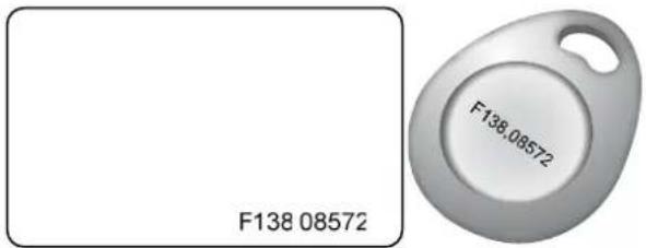 For Card Only Mode, both the GV-AS ID F Card / Tag and the GV-AS ID Card / Tag are supported, but the GV-AS ID F Card / Tag cannot contain any fingerprint data. For Card Only Mode, both the GV-AS ID F Card / Tag and the GV-AS ID Card / Tag are supported, but the GV-AS ID F Card / Tag cannot contain any fingerprint data. |
| GV-HUB V2 | The GV-Hub V2 adds four RS-232/RS-485 serial ports through the computer's USB port, allowing connection between the fingerprint reader and the computer.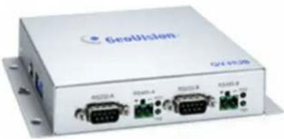 |
| GV-COM V2 | The GV-COM V2 can convert the standard RS-232 signal, through USB connector, to RS-485 signal, allowing connection between the fingerprint reader and the computer.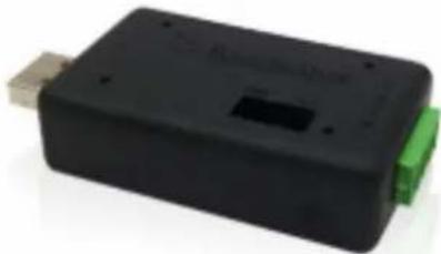 |
| GV-NET/IO Card V3.1GV-NET/IO Card V3.2 | The GV-NET/IO Card is a RS-485 / RS-232 interface converter that provides 4 inputs and 4 relay outputs. Using the GV-NET/IO Card, you can connect the fingerprint reader to the computer.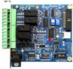 |
| PC Service Package | The package includes a USB cable for connecting the fingerprint reader to a computer and a reader mount to hold the reader for fingerprint enrollment. See 7. Upgrading Firmware later.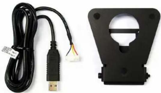 |
| Note:1. For Card + Fingerprint Mode, GV-GF Fingerprint Readers can only work with GeoVision's user cards and tags.2. For Card + Fingerprint Mode, be sure that your user card has the serial number starting with the letter F; otherwise, you cannot record the fingerprints to the user card.3. GV-HUB V2, GV-COM V2, GV-NET/IO Card and PC Service Package are only compatible with GV-GF1911 / 1912. | |
1.3 Serial Number / MAC Address
To find the serial number of GV-GF1911 / 1912, see the XID number on the back of fingerprint reader.
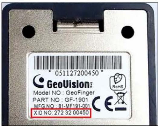
Figure 1-1
For GV-GF1921 and GV-GF1922, you can find the MAC address on the back of the device.
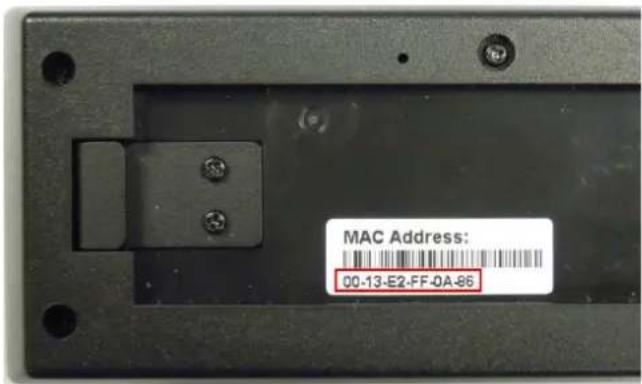
Figure 1-2
You can also find the serial number (for GV-GF1911 / 1912) or the MAC address (for GV-GF1921 / 1922) using the GV-Net Module Utility supplied on the software CD. For details to use the utility, see GV-Net Module Utility, Chapter 10.
1.4 Installation
Follow the steps below to install the GV-GF1921 / 1922 on wall.
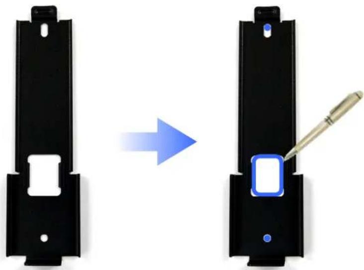
- Place the mounting plate on the wall as illustrated below.
natural_image
Two black metal components with a blue square button and a screwdriver, shown before and after an arrow indicating transformation (no text or symbols)Figure 1-3
- Mark the location of the 2 holes and the rectangle as labeled above.
- Drill the rectangle to create a space for running the cables and wires.
- At the 2 dots, drill a hole slightly smaller than the plastic screw anchors provided.
- Insert the 2 plastic screw anchors in the drilled holes.
- Place the mounting plate on the wall and secure with the 2 standard screws provided.
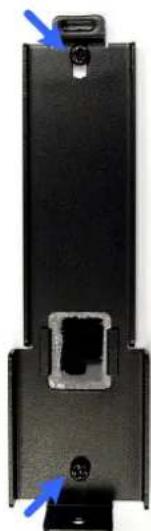
natural_image
Black rectangular device with a central port and two blue arrows pointing to the side (no visible text or symbols)Figure 1-4
- Place fingerprint reader on the mounting plate and thread the cables through the rectangular hole.
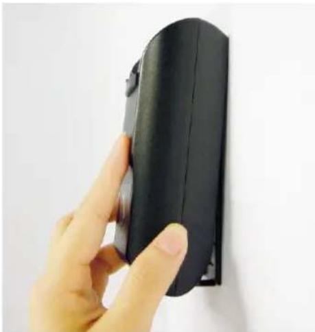
natural_image
Hand holding a black rectangular device against a plain white wall (no text or symbols visible)Figure 1-5
- Secure the security screw on the bottom.
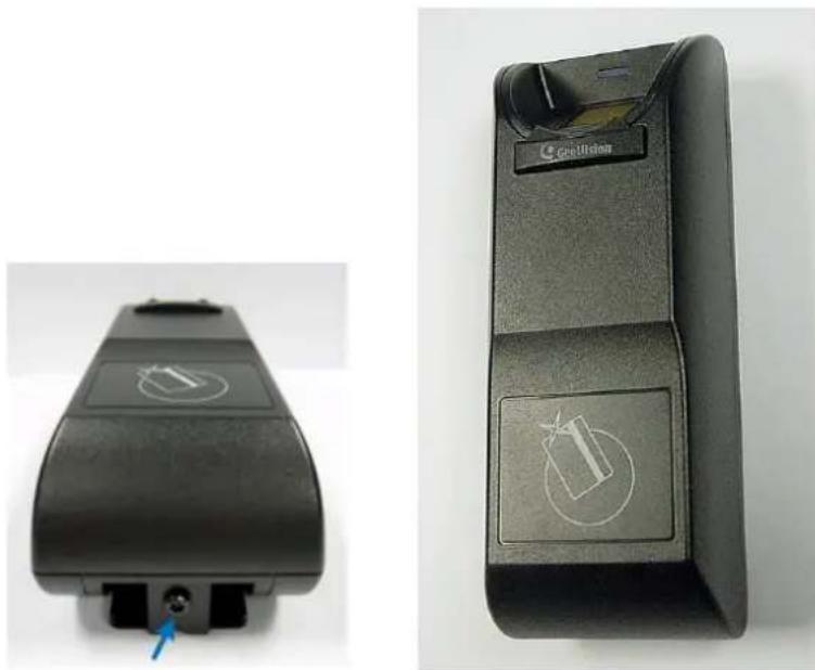
natural_image
Two black industrial control box components with circular buttons and a small blue arrow pointing to a component (no visible text or symbols)Figure 1-6
Chapter 2 Connecting GV-AS Controller
Depending on the model of the fingerprint reader, three types of communication links are provided: Wiegand, RS-485 and TCP/IP (LAN).
2.1 Connecting through Wiegand Interface
Supported models: GV-GF1911 / 1912.
2.1.1 Physical Connection
The fingerprint reader is connected with an unshielded 9-wire cable of 100 cm / 3.28 feet. Connect these 4 unshielded wires to the assigned pins on the Wiegand interface of the GV-AS Controller: Red, Black, White and Green wires.
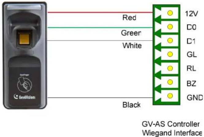
Figure 2-1
The table below shows the wire assignments of the fingerprint reader used for Wiegand connection.
| Wire | Red | Black | White | Green | Yellow | Blue | Orange | Brown | Silver | |
| Function | 12V | GND | Data-1 | Data-0 | N/C | N/C | N/C | N/C | N/C | |
For the wiring of extending distance it is recommended to use the standard RS-485 cable (a twisted pair of 24 AWG wires). The maximum distance of the Wiegand output cable should be restricted to a length of 30 meters (98.43 feet).
2.1.2 Software Configuration
To define the fingerprint reader connected to the GV-AS Controller. On the Web interface of GV-AS Controller, click Wiegand Setting in the left menu. The Wiegand Configuration page appears. Select the function, e.g. Door/Gate 1 Entry, that the fingerprint reader is used for, and click Submit.
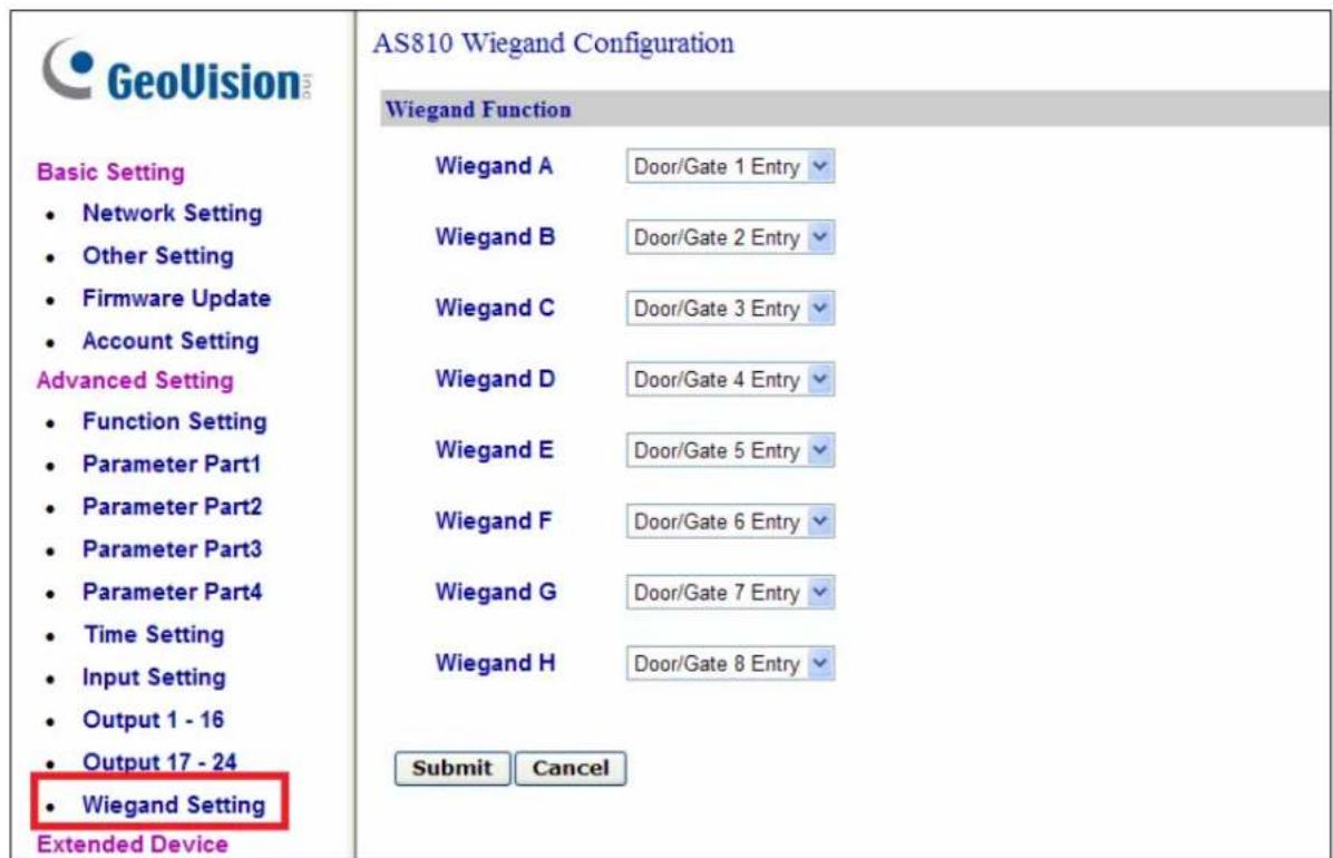
Figure 2-2
2.2 Connecting through RS-485 Interface
Supported models: GV-GF1911 / 1912.
2.2.1 Physical Connection
Use the terminal block on the above four reader models for RS-485 connection to the GV-AS Controller.
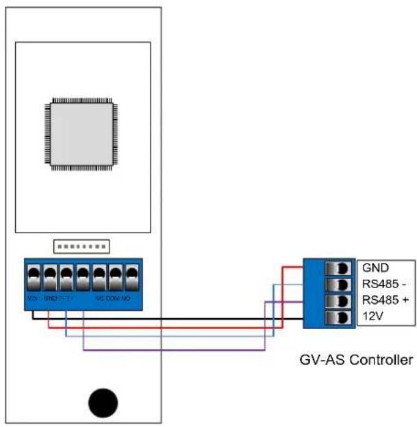
GV-GF1911 / 1912
Figure 2-3
The table below shows the pin assignments of the fingerprint reader used for RS-485 connection.
| Pin | VIN | GND | T- | T+ |
| Function | 12V GND RS-485 - RS-485 + | |||
2.2.2 Software Configuration
To define the fingerprint reader connected to the GV-AS Controller, on the Web interface of GV-AS Controller, click Extended Reader in the left menu. The Extended Reader Configuration page appears.
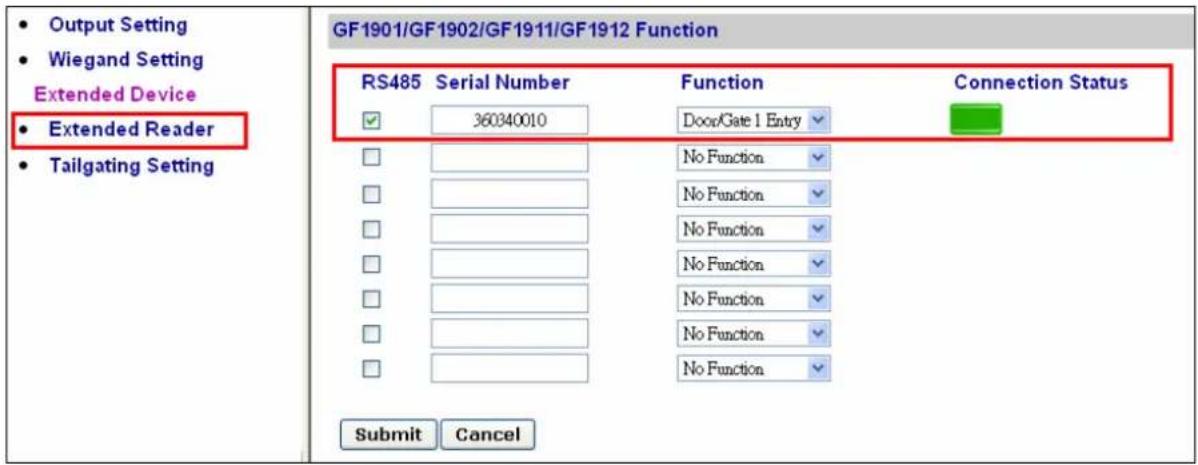
Figure 2-4
Type Serial Number of your fingerprint reader (See 1.3 Serial Number / MAC Address), and select Function that the fingerprint reader is used for, and click Submit. If the fingerprint reader is detected, the Connection Status field will be green.
IMPORTANT: For RS-485 connection, make sure to check the RS485 box before the serial number to establish connection.
2.3 Connecting through TCP/IP Interface
Supported models: GV-GF1911 / 1912 / 1921 / 1922
Note: The GV-GF1921 / 1922 can also work as a standalone device without connecting to a GV-AS Controller. For details, see 7. A Standalone Fingerprint Reader.
2.3.1 Physical Connection
The fingerprint reader and GV-AS Controller can be physically connected through LAN. Prepare a 12V DC power adapter to connect the fingerprint reader to a power source.
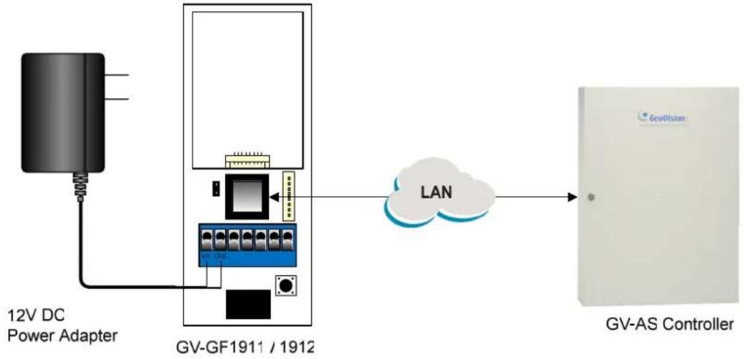
flowchart
graph LR
    A["12V DC Power Adapter"] --> B["GV-GF1911 / 1912"]
    B --> C["LAN"]
    C --> D["GV-AS Controller"]
Figure 2-5
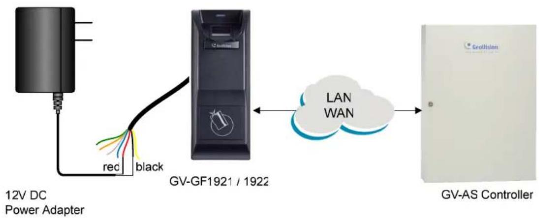
flowchart
graph LR
    A["12V DC Power Adapter"] -->|red black| B["GV-GF1921 / 1922"]
    B --> C["LAN WAN"]
    C --> D["GV-AS Controller"]
Figure 2-6
The table below shows the pin assignments of the fingerprint reader used for power connection.
| Pin | GV-GF1911 / 1912 | VIN | GND |
| GV-GF1921 / 1922 | Red wire Black wire | ||
| Function | 12V | GND | |
Note:
- Make sure your GV-AS Controller and GV-ASManager support the network connection with the fingerprint reader. See Firmware and Software Compatibility.
- Instead of using a 12V DC power adapter, you also connect the fingerprint reader to GV-AS Controller for power supply.
2.3.2 Accessing the Web Interface
By default, the fingerprint reader is assigned with an unused IP address by the DHCP server when the fingerprint reader is connected to the network. This IP address remains unchanged unless you unplug or disconnect your fingerprint reader from the network.
Note: If your router does not support DHCP, the default IP address will be 192.168.0.10. The default login ID and password are admin.
Follow the steps below to look up the IP address of your fingerprint reader / GV-AS Controller and access the Web interface:
- Look up the IP address using GV-Net Module Utility.
A. Install GV-Net Module Utility from the Software CD.
B. Run the utility. The GV-Net Module Utility window appears and automatically searches for the GV-AS Controller and GV-GF1911 / 1912 / 1921 / 1922 on the same LAN.
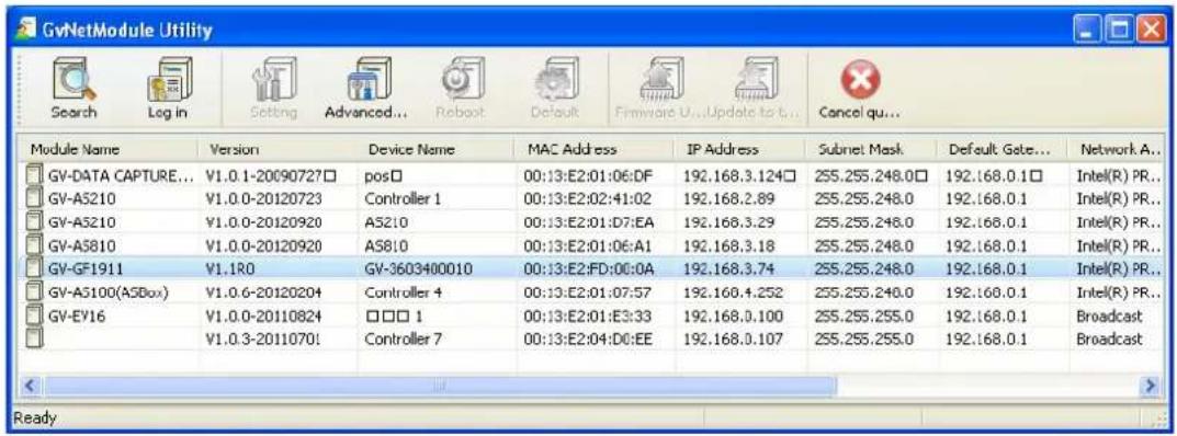
Figure 2-7
C. Click Module Name or MAC Address to sort.
D. Find the IP address of your device.
- You can access the Web interface using any of the following method:
• Right-click the device on GV-Net Module Utility and select Advanced Setting.
- Type the IP address into the Web browser.
- Type ID and password. The default ID and password are admin.
2.3.3 Software Configuration
To connect the fingerprint reader and GV-AS Controller through the network, you need to provide information such as a serial number, MAC address and IP address for your fingerprint reader and GV-AS Controller to locate and connect to each other.
A. Define fingerprint reader on GV-AS Controller.
-
Log in the Web interface of GV-AS Controller. For details, see 2.3.2 Accessing the Web Interface.
-
On the Web interface of GV-AS Controller, click Extended Reader in the left menu. The Extended Reader Configuration page appears.
3. For GV-GF1921 / 1922:
Type the MAC address of your fingerprint reader in the Serial Number column under the GV-Reader/CR420/GF1921/GF1922 Function section. Do not select the RS-485 box.
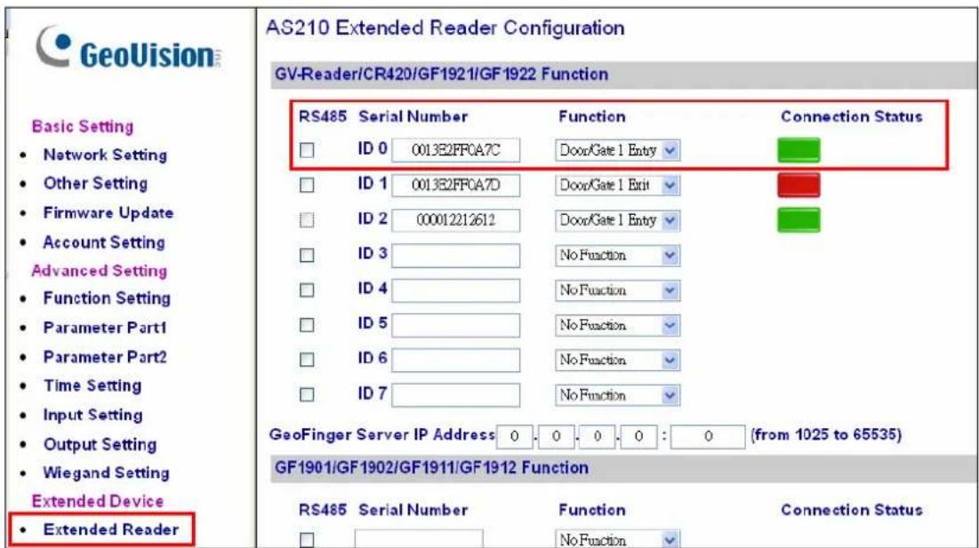
Figure 2-8
In the GeoFinger Server IP Address field, you can type the IP address and port of the GV-ASManager's GeoFinger Server in order for GV-ASManager to receive data from the GV-GF1921 / 1922 listed on this page during remote fingerprint enrollment. In addition, the GV-AS Controller will be connected to the GV-GF1921 / 1922 listed. You can therefore skip the steps in B. Specify the GV-AS Controller on your fingerprint reader if you fill in the GeoFinger Server IP Address.
For GV-GF1911 / 1912:
Type the Serial Number of your fingerprint reader in the Serial Number column under the GF1901/GF1902/GF1911/GF1912 Function section.
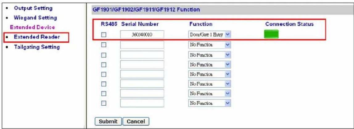
Figure 2-9
Note: Select the RS-485 checkbox only if the GV-GF1911 / 1912 is connected to the controller through RS-485 connection. For TCP/IP connection, do not check the RS485 box.
For details on how to look up the serial number or the MAC address, see 1.3 Serial Number / MAC Address.
- Use the Function drop-down list to specify which door the fingerprint reader is connected to.
- Click Submit. If the fingerprint reader is detected, a green bar appears in the Connection Status field.
B. Specify the GV-AS Controller on your fingerprint reader.
- Log in the Web interface of the fingerprint reader. For details, see 2.3.2 Accessing the Web Interface.
- For GV-GF1911 / 1912, click SETTINGS and select GV-AS Controller. This page appears. Type the IP address of GV-AS Controller and click Save.
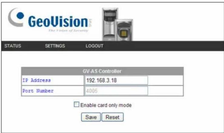
Figure 2-10
- For GV-GF1921 / 1922, select Other Settings. This page appears. Type the IP address or domain name of GV-AS Controller and click Submit.
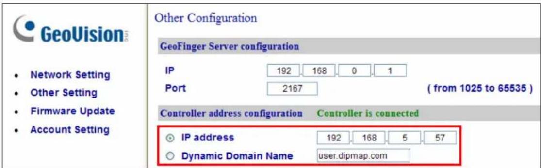
Figure 2-11
If the connection is established, the message "Controller is connected" appears (Figure 2-11) and a green bar appears on in the Connection Status field of the GV-AS Controller (Figure 2-8 and Figure 2-9).
Note: If the fingerprint reader fails to connect to the GV-AS Controller, the reader beeps (for GV-GF1911 / 1912) or the light turns purple (for GV-GF1921 / 1922) until the connection is established.
Chapter 3 Fingerprint Only Mode
The Fingerprint Only mode must work with the GV-ASManager software and the GV-GF1911 / GV-GF1921 / GV-GF1922 reader to enroll fingerprints. You must first enroll fingerprint data using GV-ASManager and then upload the fingerprints to the fingerprint readers. To gain access, the user's fingerprint must match the enrolled fingerprint.
3.1 Enrolling Fingerprints
There are two ways to enroll fingerprints: locally and remotely.
For local fingerprint enrollment, a GV-GF1911 / 1921 / 1922 needs to be connected to GV-ASManager, and the user needs to register his or her fingerprints at the site of the GV-ASManager.
For remote fingerprint enrollment, first enroll empty fingerprints for a user on the GV-ASManager. The user can then go to a connected GV-GF1921 / 1922 at a later time, and register his or her fingerprints using an assigned card. This function is useful when the user is not around GV-ASManager.
Note: The enrolled fingerprints will be saved on the fingerprint reader instead of on the GV-ASManager.
3.1.1 Enrolling Fingerprints Locally
There are two ways to enroll fingerprint data locally:
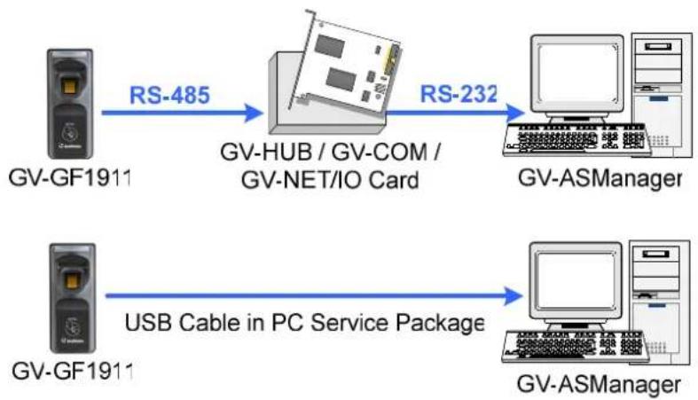
• GV-GF1911: RS-485 Connection with GV-ASManager
You need to physically connect GV-GF1911 to the computer running GV-ASManager through RS-485 connection. To establish RS-485 connection to the computer, a RS-485 to RS-232 converter, such as GV-COM, GV-Hub, GV-NET/IO Card or the USB cable in PC Service Package (optional accessory), is required.
flowchart
graph LR
    A["GV-GF1911"] -->|RS-485| B["GV-HUB / GV-COM / GV-NET/IO Card"]
    B -->|RS-232| C["GV-ASManager"]
    D["GV-GF1911"] -->|USB Cable in PC Service Package| E["GV-ASManager"]
Figure 3-1
• GV-GF1921 / 1922: TCP/IP Connection with GV-ASManager
GV-ASManager and GV-GF1921 / 1922 can be connected through TCP/IP connection.
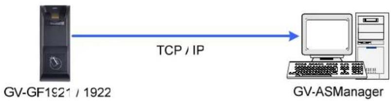
flowchart
graph LR
    A["GV-GF1921 / 1922"] -->|TCP / IP| B["GV-ASManager"]
Figure 3-2
Note:
- Fingerprint enrollment does not support Wiegand connection.
- After connecting GV-HUB, GV-COM, GV-NET/IO Card or USB Cable to the computer, you must install the driver from the supplied software CD.
Enrolling Fingerprints Locally on GV-ASManager
Before you start enrolling fingerprints, make sure you have added cards, created user accounts and assigned cards to the users. See 4.3 Setting Cards and 4.6 Setting User in GV-ASManager User's Manual. Follow the steps below to enroll the fingerprints on the GV-ASManager.
Note: Each user's fingerprints need to go along with a card number. If you do not have cards or card readers, you can create virtual card numbers to represent the enrolled fingerprints.
- On the menu bar of GV-ASManager, click Personnel and select Users. The User List window appears.
- Double-click one user listed in the window. The User Setup dialog box appears.
- Click the Fingerprint tab. This dialog box appears.
![User Setup General Home Business User Define Fingerprint Scan Connection Type TCP/IP IP Address: Port: 192.168.0.19 2167 Search Anti-duress: Left hand: Thumb: [026] 245-15502 Right hand: Forefinger: Middle finger: [026] 245-15502 Right hand: Ring finger: Little finger: Right hand: Thumb: [026] 245-15502 Forefinger: Middle finger: Ring finger: Little finger: OK Cancel](/content/2026/05/921807/images/f9b1aad3d08f1e2460b7f2e6d6468a414490e691c826e382142cc391ac3be4d4.jpg)
Figure 3-3
- Establish connection between GV-ASManager and GV-GF1911 / 1921 / 1922.
■ GV-GF1911: Select COM for Connection Type and click Search to detect the GV-GF1911 connected.
GV-GF1921 / 1922: Select TCP/IP for Connection Type. Type the IP Address and Port of the GV-GF1921 / 1922 or you can also click Search to detect available fingerprint readers on the LAN.
- In the Left Hand and Right Hand sections, click any finger square and select Enroll Fingerprints.
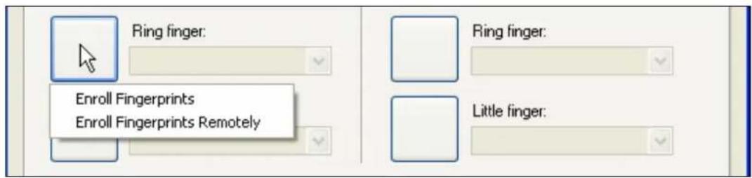
Figure 3-4
-
Place the specific finger on the fingerprint reader. It is required to register the same fingerprint twice to complete the enrollment. All ten fingerprints of a user can be enrolled.
-
Use the drop-down list to assign a card to the fingerprints.
-
To delete the enrolled fingerprint, place the mouse pointer on the desired fingerprint image. The ✗ button appears. Click the button to delete the fingerprint.
-
For the Anti-duress function, select a fingerprint from the Anti-duress drop-down list. When the user is forced to open the door under threat, he can present the designated finger to activate an alarm and send a warning signal to the GV-ASManager.
-
Click OK to apply the settings.
3.1.2 Enrolling Fingerprints Remotely (GV-GF1921 / 1922 Only)
Before you start enrolling the fingerprint, make sure you have added cards, created user accounts, and assigned cards to the users. See 4.3 Setting Cards and 4.6 Setting User in GV-ASManager User's Manual. Follow the steps below to remotely enroll fingerprints on a GV-GF1921 / 1922.
- On the menu bar of GV-ASManager, click Personnel and select Users. The User List window appears.
- Double-click one user listed in the window. The User Setup dialog box appears.
- Click the Fingerprint tab.
- In the Left Hand and Right Hand sections, click a finger square and select Enroll Fingerprints Remotely.
![User Setup General Home Business User Define Fingerprint Scan Connection Type COM COM Port: Device ID: 1 0 Search Anti-duress: [L] Middle finger Left hand: Thumb: [026] 255-45785 Forefinger: Middle finger: [026] 255-45785 Ring finger: Enroll Fingerprints Enroll Fingerprints Remotely Right hand: Thumb: [026] 255-45785 Forefinger: Middle finger: Ring finger: Little finger: OK Cancel](/content/2026/05/921807/images/9c97f09aa3304d993f76d07d7d285d46f00c0971a680e19439fe55a8b9600e13.jpg)
Figure 3-5
Note: For remote fingerprint enrollment, you do not need to select Connection Type or type the IP address of the fingerprint reader at the top of the page.
- Use the drop-down list to assign a card to the empty fingerprint.
- Repeat steps 4 and 5 for other fingers if needed.
- To delete the empty fingerprints, place the mouse pointer on the desired finger square. The ✗ button appears. Click the button to delete the fingerprint.
- For the Anti-duress function, select a finger from the Anti-duress drop-down list. When the user is forced to open the door under threat, he can present the designated finger to activate an alarm and send a warning signal to the GV-ASManager.
- Click OK to apply the settings.
Next, refer to the section below to upload the empty fingerprints to GV-GF1921 / 1922. The user can then register fingerprints anytime by swiping the assigned card and registering the same finger twice at the GV-GF1921 / 1922 specified in Figure 3-11.
If multiple empty fingerprints have been enrolled for the user, have the user register left hand before right hand and in the order of thumb, forefinger, middle finger, ring finger and little finger. Using Figure 3-5 as an example, register in the order of left hand thumb, left hand middle finger, right hand thumb.
Allowing GV-GF1921 / 1922 to Transmit Data Back to GV-ASManager
To allow GV-GF1921 / 1922 to transmit data back to GV-ASManager for remote fingerprint enrollment, you must go to the Web interface of the GV-AS Controller or the GV-GF1921 / 1922 to complete the settings below. See 2.3.2 Accessing the Web Interface for details on how to access the Web interface.
Complete setting A OR B:
A. Go to the Web interface of the GV-GF1921 / 1922, click Other Setting in the left menu, and type the IP address and Port number of the GV-ASManager's GeoFinger Server.

Figure 3-6
B. Go to the Web interface of the GV-AS Controller, click Extended Reader in the left menu, type the IP address and Port number of the GV-ASManager's GeoFinger Server.
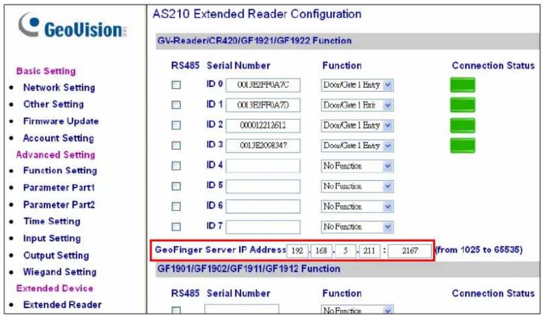
Figure 3-7
Note: The GeoFinger Server IP Address is the IP Address of the computer running GV-ASManager. The GeoFinger Server port can be located in GV-ASManager by selecting Tools > Servers > GeoFinger Server.
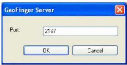
Figure 3-8
3.2 Uploading Fingerprints to Fingerprint Readers
There are two ways to upload enrolled fingerprints from GV-ASManager to fingerprint readers.
For GV-GF1911 / 1912, data can be sent to the GV-AS Controller through network connection and then sent to GV-GF1911 / 1912 through RS-485.
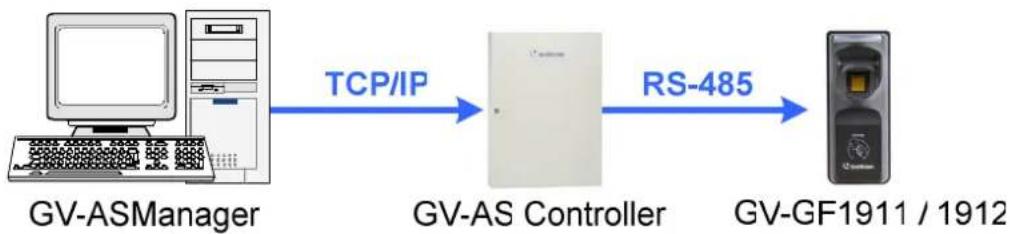
flowchart
graph LR
    A["GV-ASManager"] -->|TCP/IP| B["GV-AS Controller"]
    B -->|RS-485| C["GV-GF1911 / 1912"]
Figure 3-9
For GV-GF1911 / 1912 / 1921 / 1922, data can be sent directly from GV-ASManager through TCP / IP.
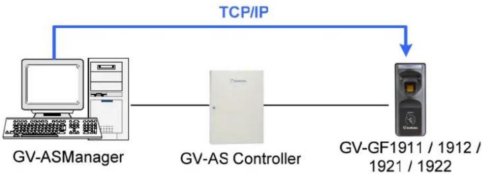
flowchart
graph TD
    A["GV-ASManager"] --> B["GV-AS Controller"]
    B --> C["GV-GF1911 / 1912 / 1921 / 1922"]
    D["TCP/IP"] --> B
Figure 3-10
To upload data from GV-ASManager to the fingerprint reader, follow the instruction below.
A. Connect GV-ASManager and Fingerprint Reader
- On the menu bar of GV-ASManager, click Setup and select Devices.
- Double-click a controller and select a Gate tab. This dialog box appears.
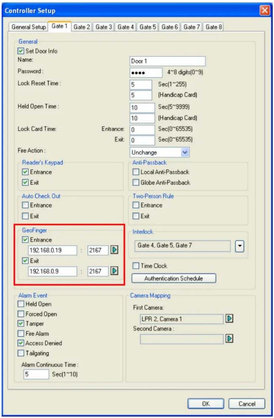
Figure 3-11
- If your fingerprint reader is connected to GV-AS Controller through RS485 (Figure 3-4), select Entrance or Exit under GeoFinger section without typing an IP address/MAC address or serial number.
If your fingerprint reader is connected to GV-AS Controller through TCP/IP, define the fingerprint reader. Under GeoFinger section, select Entrance or Exit and type the fingerprint reader's IP address and port or the following information:
- For GV-GF1911 / 1912, type gv- and the 10-digit serial number. For example: GV-0123456789
- For GV-GF1921 / 1922, type the machine name (Fig 8-1). For example: GV-0013e2ff0a76
For details on looking up the IP address, serial number or machine name, see 2.3.2 Accessing the Web Interface.
B. Select and Upload Fingerprints Data from GV-ASManager to Fingerprint Readers
4. On the menu bar of GV-ASManager, click Setup and select Fingerprint Access. This dialog box appears.
![Fingerprint Access Controller 9 9 D15-01 Treding F 9 D15-02 Server Ro 9 D15-03 Staircase 9 D15-10 Meeting Controller 10 10 D16-57 VIP Con 10 D16-46 Door Le 10 D16-45 Door Le Controller 12 Taipei Irvine Tokyo Cardholder Fingerprint Card Number < Add Remove -> Total Fingerprints: 0 Total Fingerprints: 431 Cardh... Fingerprint Card Number Ca... Dilys...[L] Thumb 2222222222 32 YT...[L] Forefinger 3093696133 32 And...[L] Forefinger 1960448955 32 John...[R] Forefinger 2970242693 32 Jren...[L] Forefinger 3103362693 32 Lydi...[R] Forefinger 3082653317 32 Eric ...[L] Thumb 3150286469 32 Jesli...[L] Forefinger 3171700357 32 Jo Jo...[R] Thumb 2980974213 32 Zhe...[R] Forefinger 3179826821 32 Shil...[L] Forefinger 2953203333 32 Adel...[L] Forefinger 3138621061 32 Shiel...[L] Thumb 3141242501 32 Kelly...[L] Forefinger 3071512197 32 Dot...[L] Thumb 2006062011 32 Dot...[L] Forefinger 2050429883 32 Ah...[L] Forefinger 2145203131 32 Ang...[L] Forefinger 2044138427 32 Zep...[R] Forefinger 2061882299 32](/content/2026/05/921807/images/7a6ecb2e2bb0cd1b2fea2feee2da2f492d4ef4ad88407dbce29f7b1bfb0353ed.jpg)
Figure 3-12
- To upload the fingerprints to a door or a controller, select the desired Door/Gate or controller in the top-left panel. If you have assigned multiple controllers to a door group, select the desired door group in the bottom-left panel. See Uploading Fingerprints to Controllers Using Door Groups later in this chapter to see how to set up door groups.
- Select the desired fingerprint data on the right side. The Add button becomes available.
- Click the Add button to upload the selected fingerprint data to the selected Door/Gate or door group. When the uploading is complete, check marks will appear in the In (Enter) or Out (Exit) columns. The resulting window after uploading may look like this:
![Fingerprint Access Controller 9 Gate A Gate B Gate C Gate D Controller 10 10 D16-57 VIP Con 10 D16-16 Door L Taipei Irvine Tokyo Cardh... Fingerpr... Card N... C... In Out Dot... [L] Thu... 200606... 32 ✓ ✓ Dily... [L] Thu... 222222... 32 ✓ ✓ Dot... [L] Foref... 205042... 32 ✓ ✓ Kell... [L] Foref... 307151... 32 ✓ ✓ An... [L] Foref... 196044... 32 ✓ ✓ YT ... [L] Foref... 309369... 32 ✓ ✓ Joh... [R] Fore... 297024... 32 ✓ ✓ < Add Remove -> Total Fingerprints: 7 Total Fingerprints: 42](/content/2026/05/921807/images/7ba51247ff6f1ee5e04eb9c64eca63f7167d9e045679aba366a08ad96bf91277.jpg)
Figure 3-13
Tip:
- If some green checkmarks are missing in the In or Out columns, right-click the door / gate in the Device View on the main screen, and select Sync GeoFinger to re-upload the data.
- Each fingerprint reader can store up to 1,900 fingerprints.
3.3 Uploading Fingerprints Using Door Groups
When a large number of GV-AS Controllers are connected to the GV-ASManager, you can organize the GV-AS Controllers into different door groups. Using door groups, you can quickly upload fingerprints to all the GV-AS Controllers in a door group instead of uploading to each controller one by one.
- On the menu bar of GV-ASManager, click Setup and select Door groups. This window appears and the connected controllers are listed on the right.
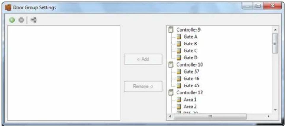
Figure 3-14
- Click the Add Group button. A new group is created.
- Click the new group and click the Rename Group button ☐ to rename the group.
- Select the door group and then select the controllers to add to the group.
- Click the Add button. The selected GV-AS Controllers are now assigned to the group.
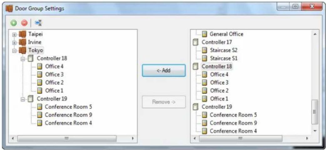
Figure 3-15
3.4 Using the Fingerprint Reader
After you connect the fingerprint reader to the controller and enroll the fingerprints, scan your finger to gain access.
- If the presented fingerprint matches any record in the fingerprint reader, the light will turn from blue to green. Access signal will be passed to the controller and the access will be granted.
- If the presented fingerprint does NOT match the record in the fingerprint reader, the light will turn from steady blue to yellow and the reader will beep for three times. Then the light will come back to a steady blue. The reader will not pass access signal to the controller and the access will be denied.
Note: The light on fingerprint reader turns red if the access is not within the established schedule on GV-AS Manager.
Chapter 4 Card + Fingerprint Mode
4.1 Enrollment
The user's fingerprints are stored in the user card and each user card can store up to 2 fingerprints. The user must gain access by scanning both the user card and the finger.
Cards Required for Enrollment
- Manager Enroll Card (supplied in the package)
- User Card
Note: For Card + Fingerprint Mode, GV-GF Fingerprint Readers can only work with GV-AS ID F cards and tags. Every GV-AS ID F card or tag can only store 2 fingerprints.
Enrollment Procedure
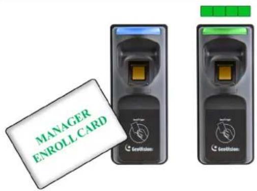 | Step 1:In the standby mode, the light is blue on.Present the Manager Enroll Card. The light starts blinking green. |
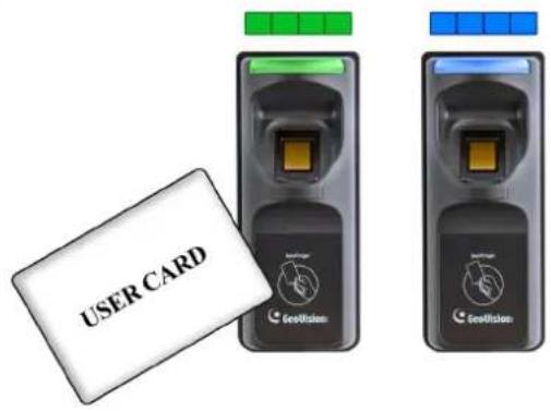 | Step 2:Present the User Card till the light blinks blue.Or present the Manager Enroll Card to exit the enroll mode. |
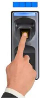 | 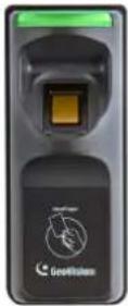 | 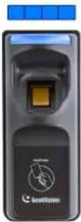 | Step 3:GV-GF1911/1912With the light blinking blue, scan your fingerprint and withdraw when the reader beeps. The light turns green and then back to blue again. |
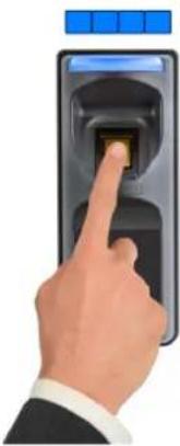 | 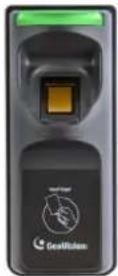 | 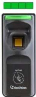 | Scan the same fingerprint again till beep, and withdraw your finger. The light again turns green and then blinks green.Note: It is required to scan the same fingerprint twice to complete the enrollment. |
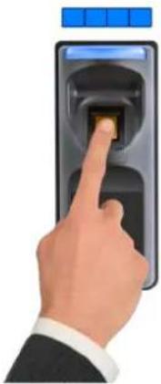 | 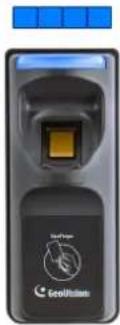 | GV-GF1921 / 1922With the light blinking blue, scan your fingerprint and withdraw only when your hear a long beep. The light blinks blue, signifying that one fingerprint has been enrolled. | |
 | Step 4:GV-GF1911 / 1912To enroll the second fingerprint, repeat step 3.GV-GF1921 / 1922To enroll the second fingerprint, press another finger on the reader while the light blinks blue. Withdraw your finger when the reader beeps. The light shall blink green. | ||
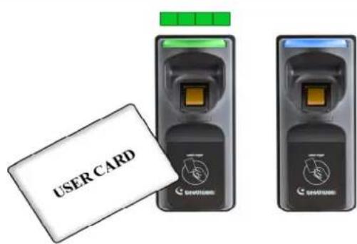
Step 5:
Present the User Card to record fingerprints till beep. The light turns green and then steady blue.
The enrollment is complete and you can use the Card Plus Fingerprint on the fingerprint reader.
Note:
-
You will need the corresponding user card when deleting an individual user. Once you lose the user card, you cannot delete its related user from the reader.
-
The new fingerprints enrolled will replace the existing enrolled fingerprints.
4.2 Deletion
Card data will be deleted from the reader and fingerprint templates will be erased from the user card.
Cards Required for Deletion
- Manager Delete Card (supplied in the package)
- User Card
Note: For Card + Fingerprint Mode, GV-GF Fingerprint Readers can only work with GV-AS ID F cards and tags.
Deletion Procedure
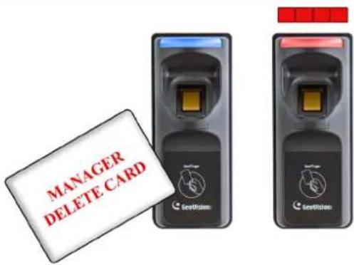 | Step 1:In the standby mode, the light is blue on.Present the Manager Delete Card. The light starts blinking red. |
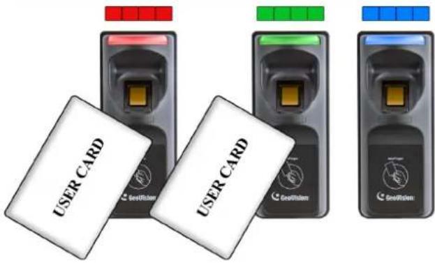 | Step 2:With the light blinking red, present the User Card. The light starts blinking green. Present the User Card again to delete all fingerprints stored in the card.When the deletion is complete, the light turns green and then steady blue. |
4.3 Using the Fingerprint Reader
After you connect the fingerprint reader to the controller, present the user card. The light on the reader will start blinking blue. Then scan your finger to gain access.
- If the presented fingerprint matches any record in the card, the light will turn from blue to green. Access signal will be passed to the controller. The access will be granted.
- If the presented fingerprint does NOT match the record in the card, the light will turn from steady blue to blinking red and beep for three times. Then the light will come back to a steady blue. The reader will not pass access signal to the controller. The access will be denied.
Note: The light on fingerprint reader turns red if the access is not within the established schedule on GV-AS Manager.
Chapter 5 Card Only Mode
This Card Only mode allows the users to gain access with a card. This mode is only supported by the fingerprint reader using MIFARE cards or GV-AS ID Cards / Tags.
For GV-GF1911 / 1912, if you are not using the GeoVision user card and tag, you need to access the Web interface and select Enable card only mode to enable the function. To access the Web interface, see 2.3.2 Accessing the Web Interface to find the fingerprint reader's IP address for login.
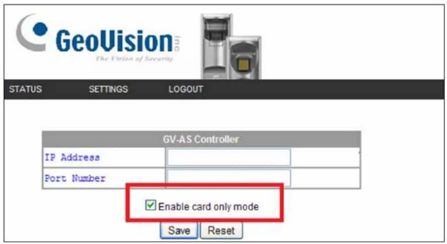
Figure 5-1
5.1 Enrollment
Before enrollment, establish a user account and assign a card to the user on the connected GV-AS Manager. For details, see 4.3 Setting Cards and 4.6 Setting User in GV-ASManager User's Manual.
To enroll, use a MIFARE card and follow the procedure below.
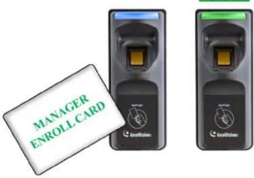 | Step 1:In the standby mode, the light is blue on. Present the Manager Enroll Card. The light starts blinking green. |
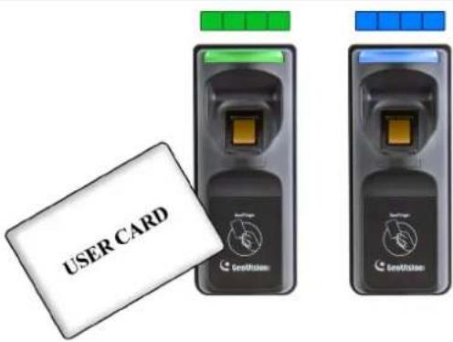 | Step 2:Present the User Card till the light blinks blue.Or present the Manager Enroll Card to exit the enroll mode. |
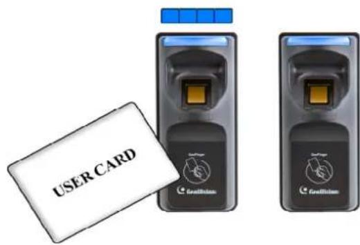 | Step 3:With the light blinking blue, present the User Card again to confirm. The light turns steady blue and the enrollment is complete. |
5.2 Deletion
To delete the access right of a card, inactivate or delete the user account established on the GV-AS Manager. For details, see 4.3 Setting Cards and 4.6 Setting User in GV-ASManager User's Manual.
5.3 Using the Fingerprint Reader
After you connect the fingerprint reader to the controller, present the card you enrolled.
- If the card is detected as an enrolled card, the light will turn from blue to green. The access signal will be passed to the controller and the access will be granted.
- If the card does not match any of the enrolled cards, the light will turn from blue to red. The access will be denied.
Note: The light on fingerprint reader turns red if the access is not within the established schedule on GV-AS Manager.
Chapter 6 Connecting an Alarm Device
You can connect one output device like a siren to the reader for warning when the access is granted.
6.1 GV-GF1911 / 1912
The example below illustrates the connection of an output device to the fingerprint reader. Connect (+) point of the output device to COM of the fingerprint reader, connect the (-) points of the output device and the external power supply together, and connect the (+) point of the external power supply to NO or NC of the fingerprint reader based on the state of the output device.
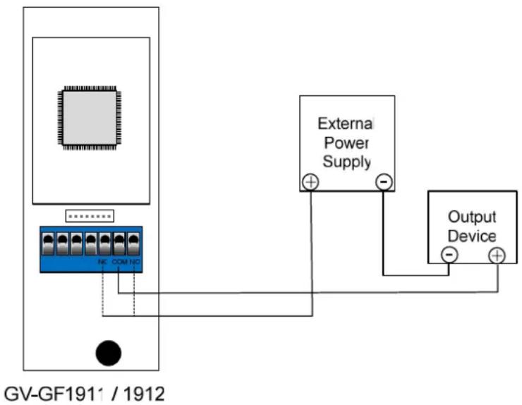
Figure 6-1
6.2 GV-GF1921 / 1922
Connect (+) point of the output device to the yellow wire (COM) of the fingerprint reader, connect the (-) points of the output device and the external power supply together, and connect the (+) point of the external power supply to the pink wire (NO) or the orange wire (NC) of the fingerprint reader based on the state of the output device. For a door sensor, connect the blue wire to the sensor.
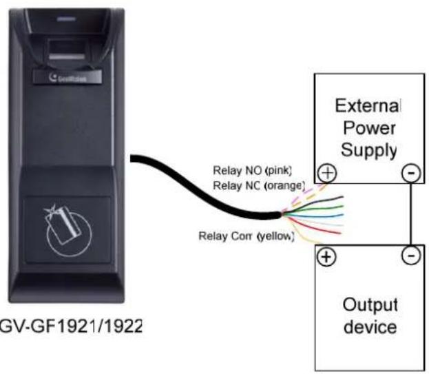
Figure 6-2
Wire Definition
| Wire Color Definition | |
| Orange | Relay NC |
| Pink | Relay NO |
| Yellow | Relay Com |
Chapter 7 A Standalone Fingerprint Reader
The GV-GF1921 / 1922 can also work on its own without connecting to GV-AS Controller and GV-AS Manager.
7.1 Physical Connection
Connect the input and output devices with the data cable. Each GV-GF1921 / 1922 can connect to 2 inputs (1 door sensor and 1 button) and 1 output (door relay).
Data Cable
| Wire Color Definition | |
| Red | +12V |
| Black | GND |
| Green IN1 (only for button input) | |
| Blue IN2 (only for door sensor) | |
| White | IN Com |
| Orange | Relay NC |
| Pink | Relay NO |
| Yellow | Relay Com |
7.2 Enabling the Local Mode
Make sure you activate local mode function of the GV-GF1921 / 1922 and configure related settings from its Web interface. To restrict enrollment and deletion to one enroll card and one delete card, type the identification number of your card. For more details, see Local mode configuration, 8.2 Other Settings.
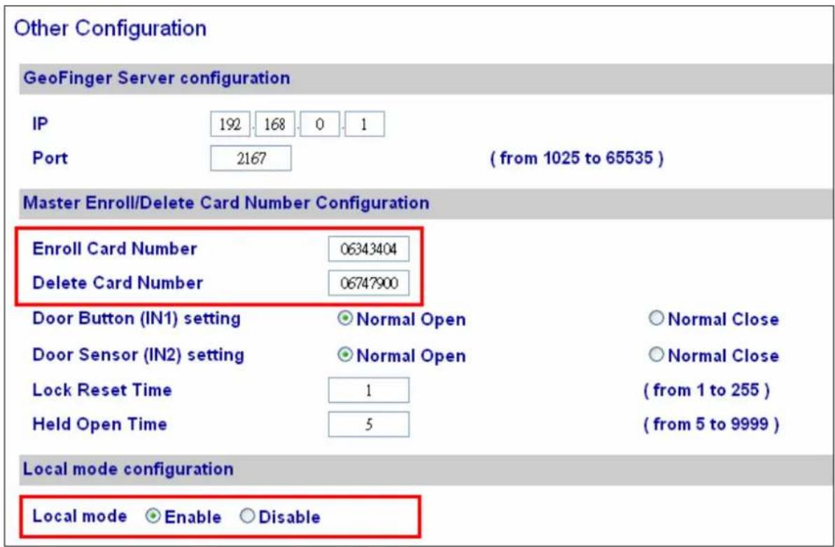
Figure 7-1
7.3 Fingerprints and Card Enrollment
After you have connected your GV-GF1921 / 1922 to power and I/O devices, you are ready to enroll fingerprints or cards with fingerprints. The standalone GV-GF1921 / 1922 supports the Fingerprint Only Mode.
7.3.1 Fingerprint Only Mode
Use any MIFARE card during enrollment for this mode.
• To enroll fingerprints, follow the steps in 4.1 Enrollment.
• To delete enrolled fingerprints, see 4.2 Deletion.
• To obtain access, see 3.4 Using the Fingerprint Reader.
Note: For this mode, it is still required to use the user cards to enroll fingerprints because each uesr's fingerprints need to go along with a card number. However, the enrolled fingerprints are stored on the reader instead of the cards.
Chapter 8 Web Interface for GV-GF1921 / 1922
The GV-GF1921 / 1922 can be configured through the Web interface. For details on accessing the Web interface, see 2.3.2 Accessing the Web Interface.
8.1 Network Settings
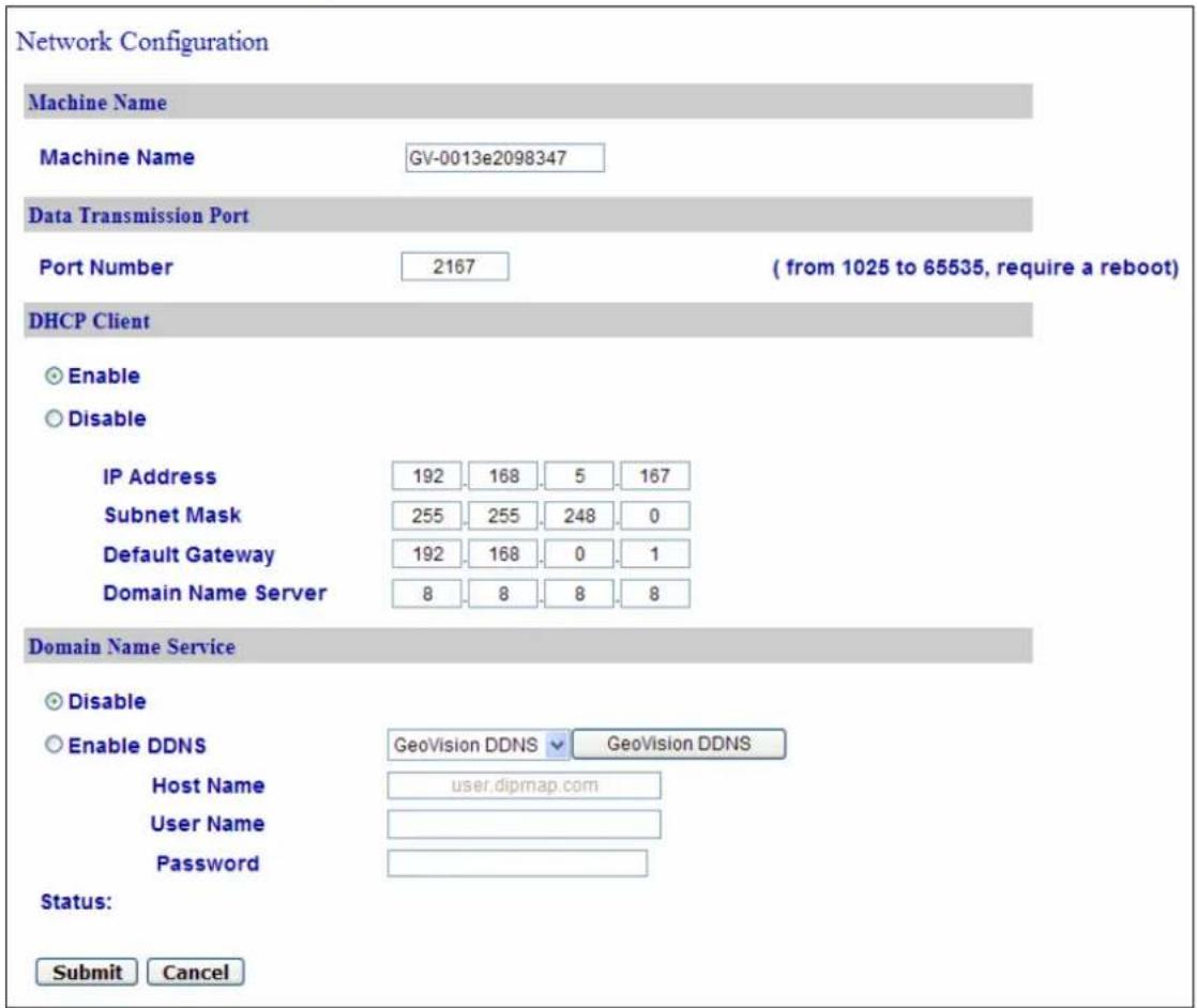
Figure 8-1
[Machine Name]
The device name is displayed. Click the space to change the device name.
[Data Transmission Port]
Make sure this port matches the port you defined for the reader on the Controller Setup page of the GV-ASManager.
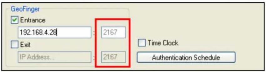
Figure 8-2
[DHCP Client]
By default, the DHCP service is enabled and when the fingerprint reader is connected to the network, it is automatically assigned an unused IP address by the DHCP server. This IP address remains unchanged unless the fingerprint reader is disconnected and reconnected to the network. If the router does not support DHCP, the default IP address will be 192.168.0.10.
To designate a fixed IP address, select Disable and specify the IP Address, Subnet Mask, Default Gateway and Domain Name Server.
Tip: You can also configure the Machine Name and IP address settings using the GV-Net Module Utility. From the GV-Net Module Utility window, double-click the device name/IP address to configure.
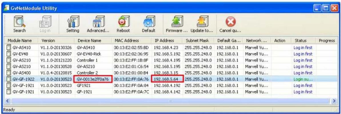
Figure 8-3
[Domain Name Service]
The Dynamic Domain Name System (DDNS) provides a convenient way of accessing the fingerprint reader when using a dynamic IP. The DDNS assigns a domain name to the fingerprint reader so that the user can log in the Web interface using the domain name, without checking the IP address every time.
To activate this function:
- Select Enable DDNS.
- Click GeoVision DDNS to register for a host name or select the service provider (GeoVision DDNS or DynDNS.org) you have registered, using the drop-down list.
- Type the Host Name, User Name and Password to enable the DDNS service.
- Click Submit.
8.2 Other Settings
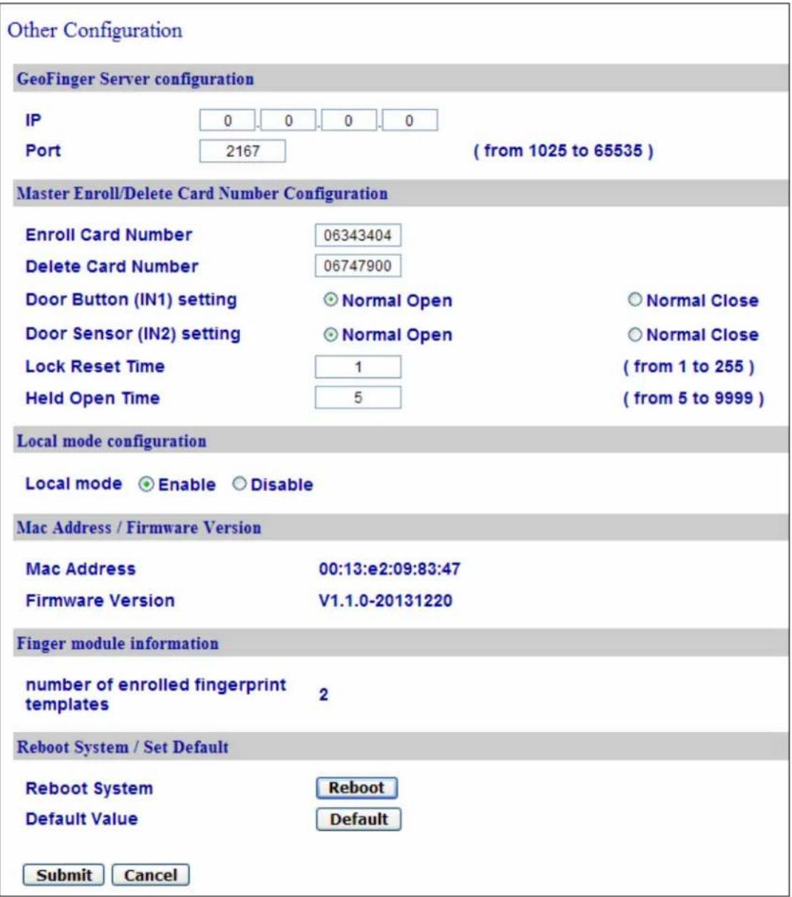
Figure 8-4
[GeoFinger Server Configuration]
Type the IP address and Port of the GV-ASManager in order for GV-GF1921 / 1922 to transmit registered fingerprints to GV-ASManager for remote fingerprint enrollment. The default port is 2167.
Note: Make sure this port matches the GeoFinger Server port on the GV-AS Manager. (GV-ASManager > Tools > Servers > GeoFinger Server)
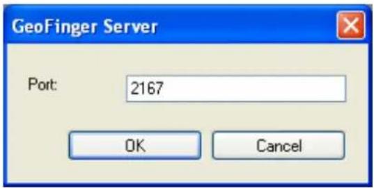
Figure 8-5
[Controller address configuration]
Type the IP address or the domain name of the GV-AS Controller to connect. This option is only available when Local Mode is disabled.
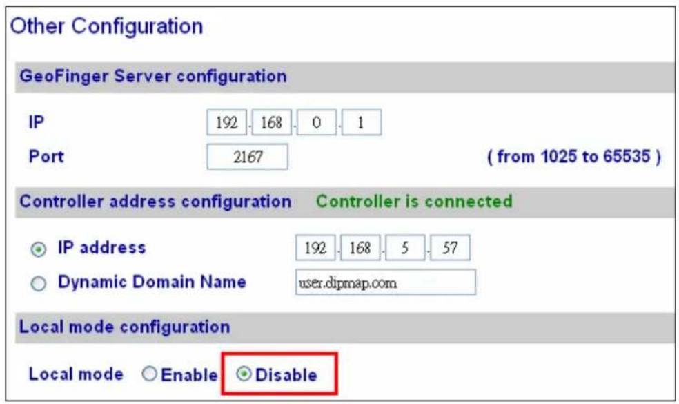
Figure 8-6
[Master Enroll / Delete Card Number configuration] This section is only available when Local Mode is enabled.
■ Enroll / Delete Card Number: To restrict enrollment and deletion to one enroll card and one delete card, type the identification number of your card
■ Door Button Setting: Specify the input states (Normal Open or Normal Close).
■ Lock Reset Time: Sets the duration (in seconds) that a door/gate remains open until it is locked again. The default is 1 second. For example, if the Lock Reset Time is 5 seconds, and access is granted, the door/gate will be automatically locked after 5 seconds.
■ H eld Open Time: Sets the duration (in seconds) that the door/gate can be held opened before an alarm is generated. The default is 5 seconds. For example, if the Held Open Time is 3 seconds, the fingerprint reader will beep when the door is held open for more than 3 seconds.
[Local mode configuration]
The GV-GF1921 / 1922 can function as a standalone device without connecting to GV-AS Controller and GV-AS Manager. This function is disabled by default. To enable this function, select Enable.
[MAC Address / Firmware Version]
Shows the device's MAC address and firmware version.
[Finger module information]
Indicates the number of fingerprints enrolled.
[Reboot System / Set Default]
Click the Reboot button to reboot the device. The fingerprint reader beeps when the reboot is complete.
Click the Default button to restore the default settings. A confirmation dialog box appears to request for closing the Web interface. Click Yes to start loading the default settings. The fingerprint reader beeps when the restoration is complete.
8.3 Firmware Update
You can upgrade your device firmware through the Web interface. For details, see 9. Upgrading Firmware.
8.4 Account Settings
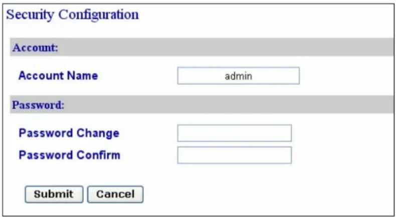
Figure 8-7
[Account]
Click to change the account name (login ID). The default login ID is admin.
[Password]
The default password is admin. To change the password, type the new password in
Password Change, type the new password again in Password Confirm and click Submit.
The password must be within 4 to 12 characters
Chapter 9 Upgrading Firmware
Upgrade your fingerprint reader firmware to the new version.
9.1 GV-GF1911 / 1912
For the user of GV-GF1911 / 1912, firmware upgrade is done through the AutoISP software, which is available on the software CD. The AutoISP software will detect the current version of your fingerprint reader and then automatically upgrade it to the new version.
9.1.1 Connecting to a Computer
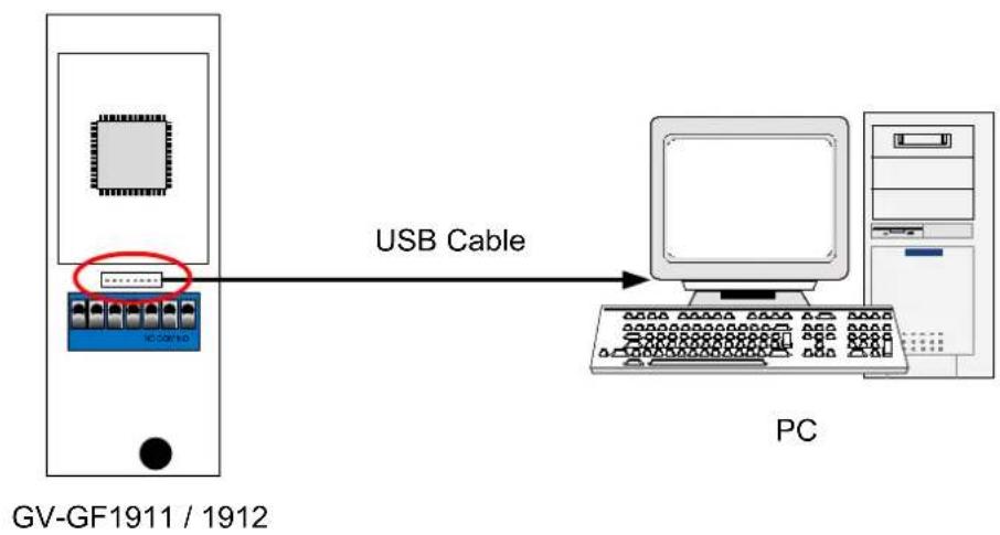
You need to connect the fingerprint reader to a computer for firmware upgrade. For this connection, one of these optional accessories is required: a USB cable (see PC Service Package, 1.2 Options), GV-HUB or GV-COM.
Using the USB Cable
Using the USB cable from the optional PC Service Package, connect the fingerprint reader to a computer as illustrated below.
flowchart
graph LR
    A["Device with 3-pin connector"] -->|USB Cable| B["PC"]
    style A fill:#f9f,stroke:#333
    style B fill:#ccf,stroke:#333
Figure 9-1
Using the GV-HUB or GV-COM
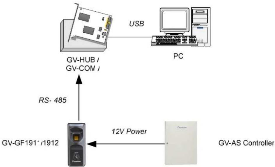
- Connect the fingerprint reader to a computer through a GV-COM or GV-HUB, which provides the RS-485 to RS-232 function.
- Power on the fingerprint reader. You can connect the 12V and GND wires from the GV-AS Controller to the fingerprint reader. The diagram below illustrates the connection among fingerprint reader, GV-COM / GV-HUB and a computer. You can also prepare a 12V DC Power Adapter to connect the fingerprint reader to a power source.
flowchart
graph TD
    A["GV-HUB / GV-COM"] -->|USB| B["PC"]
    C["GV-GF191' /1912"] -->|RS-485| A
    D["12V Power"] --> E["GV-AS Controller"]
Figure 9-2
9.1.2 Installing Software
To upgrade the firmware for the fingerprint readers, you need to install the AutoISP software from the software CD to the dedicated computer. To install firmware upgrade software, follow the steps below:
- Insert the software CD to the computer. It runs automatically and the following window pops up.
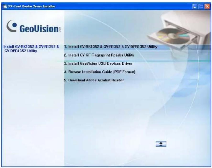
Figure 9-3
- Select Install GV-GF Fingerprint Reader Utility to install the AutoISP.
- Run AutoISP. This dialog box appears.
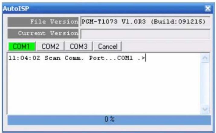
Figure 9-4
- Wait for the AutolSP detecting the COM port that the fingerprint reader is connected to and automatically upgrading the firmware.
- When the AutolSP automatically finishes firmware upgrading, the current version number shown in the dialog box will match the file version number. Click ✗ to close the dialog box.
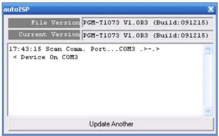
Figure 9-5
9.1 GV-GF1921 / 1922
The GV-GF1921 / 1922 can be upgraded through the Web interface or GV-Net Module Utility.
9.2.1 Upgrading Firmware through the Web Interface
- Install the GV-Net Module Utility from the Software CD.
- Run the GV-Net Module Utility and the GV-Net Module Utility window appears. It automatically searches for GV-AS Controller and GV fingerprint readers under the same LAN.
- Right-click your fingerprint reader and select Log in. This dialog box appears.
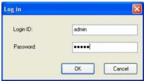
Figure 9-6
- Type the username and password to log in. The buttons on the GV-Net Module Utility become accessible.
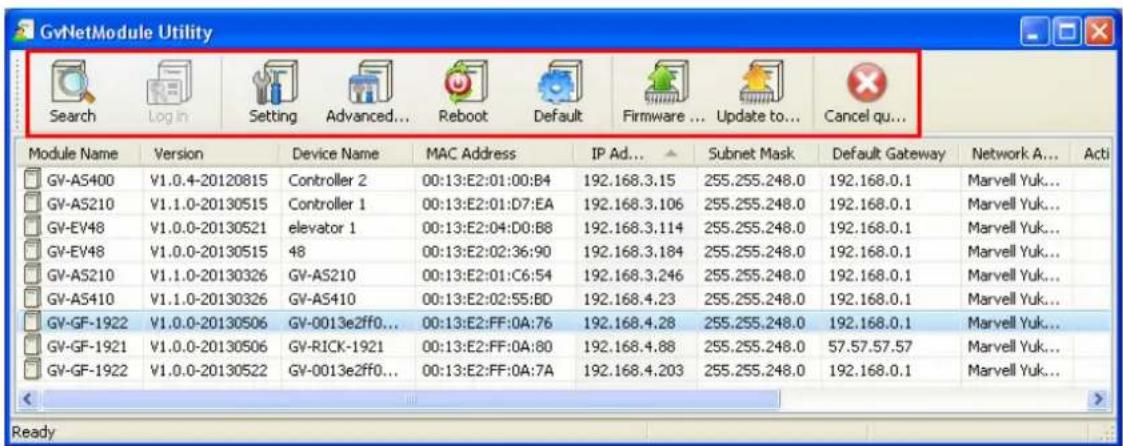
Figure 9-7
- On GV-Net Module Utility window, click the Firmware Upgrade button. This dialog box appears.
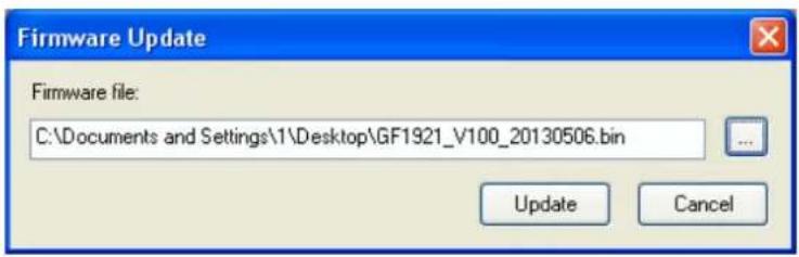
Figure 9-8
- Select a firmware file and click Update to start upgrading. You can see the upgrade progress on the GV-Net Module Utility window. The fingerprint reader beeps when the upgrade and reboot are complete.
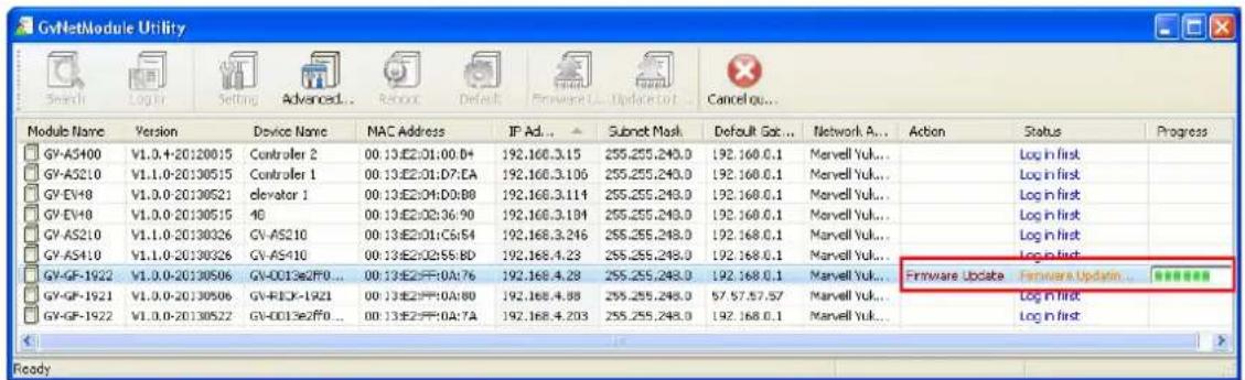
Figure 9-9
Chapter 10 GV-Net Module Utility
With the GV-Net Module Utility included in Software DVD, you can change settings and update the firmware of GV-AS Controller, fingerprint readers and GV-AS Manager.
-
Insert Software DVD, select Install GeoVision Access Control System, click GV-Net Module Utility and follow the onscreen instructions to install the program.
-
Run GV-Net Module Utility. This window appears.
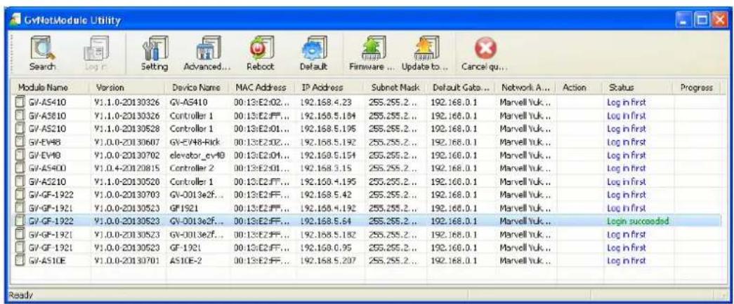
Figure 10-1
The buttons on the window:
■ Search: Click this button to locate any GV-AS Controller, GV-I/O device, fingerprint readers or GV-AS Manager on the same LAN.
■ Set Login: You can select the desired modules from the list, and click this button to log on to these modules with the same ID and password together.
■ Setting: Click this button to change the Machine Name, network connection settings, 3DES Code, Device Port, login ID and password.
■ Advanced Setting: Click this button to directly link to the Web interface of the selected module.
■ Reboot: Click this button to perform a warm boot of the selected module. This operation will keep the current configuration.
■ Default: Click this button to reset all configuration parameters to their factory settings. This may take 5 seconds to complete.
■ Firmware Update: Click this button and assign the firmware file for update.
■ Update to the latest firmware version: The GV-ASManager software comes with the latest GV-AS Controller firmware. Clicking this button can upgrade your GV-AS Controller firmware.
■ Cancel queue: Click this button to cancel the scanning using the Search button.
Specifications
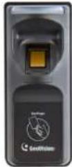
| Model | GV-GF1911 GV-GF1912 | ||
 |  | ||
| Application | Indoor use only | ||
| Communication Interface | Wiegand 26, RS-485, TCP/IP (LAN) | ||
| Sensor | Capacitive | Optical | |
| Sensing Area (H x W) 18 x 13 mm (0.71 x 0.51 in) 20 x 17 mm (0.79 x 0.67 in) | |||
| Operation Mode | Fingerprint Only (N/A for Wiegand)Card + FingerprintCard Only | ||
| Fingerprint Enrollment | (Fingerprint Only Mode) | RS-485 | Not |
| (Fingerprint + Card Mode) | RS-485, TCP/IP RS-485, TCP/IP | ||
| Firmware Upgrade | RS-485, TCP/IP | ||
| Number of Fingerprints Stored | 1,900 (for Fingerprint Only mode) | ||
| Supported Card | ISO14443A (MIFARE DESFire, MIFARE Plus and MIFARE Classic ), 13.56 MHz | ||
| Output | DC 24V, 2.5A | ||
| Power | DC 7.5V ~ 12V, Max 250mA | ||
| Operating Temperature | 0 ~ 50°C (32 ~ 122°F) | ||
| Humidity | 10% ~ 90% | ||
| Dimensions (H x W x D) | 130 x 54 x 43 mm(5.12 x 2.13 x 1.69 in) | 130 x 54 x 38 mm(5.12 x 2.13 x 1.50 in) | |
| Weight | 130 g (0.29 lb) 160 g (0.35 lb) | ||
| Certification | CE, FCC | ||
support
Note:
- All specifications are subject to change without prior notice.
- Data synchronization with GV-AS Controller and GV-ASManager through LAN is only supported with the following firmware and software versions:
• GV-ASManager: V4.0 or later
• GV-AS100 / 110 / 120: V1.06 or later
• GV-AS400: V1.04 or later
• GV-AS210 / 810 and GV-EV48: V1.0 or later
• GV-AS410: V1.1 or later
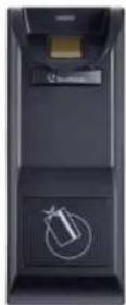
| Model | GV-GF1921 GV-GF1922 | |
 | 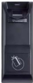 | |
| Application | Indoor use only | |
| Communication Interface | TCP/IP (10/100 Mbps Ethernet) | |
| Sensor | Capacitive | Optical |
| Sensing Area (H x W) 18 x | 13 mm (0.71 x 0.51 in) 20 x 17 mm (0.79 x 0.67 in) | |
| Operation Mode | Fingerprint Only, Card + Fingerprint, Card Only | |
| Fingerprint Enrollment | TCP/IP | |
| Firmware Upgrade | TCP/IP | |
| Number of Fingerprints Stored | 1,900 (for Fingerprint Only mode) | |
| Supported Card | ISO14443A (MIFARE DESFire, MIFARE Plus and MIFARE Classic ), 13.56 MHz | |
| Output | DC 30V, 0.3A | |
| Input | 2 Ports, dry-contact | |
| Power | DC 12V, Max 250mA | |
| Operating Temperature | 0 ~ 50°C (32 ~ 122°F) | |
| Humidity | 10% ~ 90% | |
| Dimensions (H x W x D) | 138 x 59 x 48 mm (5.43 x 2.32 x 1.89 in) | |
| Weight | 130 g (0.29 lb) 160 g (0.35 lb) | |
| Certification | CE, FCC | |
| Note:1. All specifications are subject to change without prior notice.2. GV-GF1921 / 1922 is only compatible with the following firmware and software versions.GV-ASManager: V4.0 or laterGV-AS210 / 410 / 810: V1.1 or laterGV-EV48: V1.0 or later3. GV-GF1921 / 1922 do not support third-party controllers. | ||
LED Indicator
GV-GF1911 / 1912 / 1921 / 1922 (connected with GV-AS Manager)
| LED Status Description | ||
| Blue | Steady The reader is ready for use. | |
| Flash continuously | The reader is waiting to detect a fingerprint during enrollment. | |
| The reader is waiting to detect a fingerprint to grant access under Card + Finger mode. | ||
| Green | Flash once | The detected fingerprint or card matches an enrolled account and the access is granted. |
| An enrollment is successfully deleted.*for GV-GF1911 / 1912 only | ||
| Flash continuously | The reader is waiting to detect a card during enrollment. | |
| The reader is waiting to detect a card for deletion.*for GV-GF1911 / 1912 only | ||
| Red | Flash once | The detected fingerprint or card does not match any enrolled account or when the access is not within the established schedule. The access is denied. |
| Flash continuously | The reader is waiting to detect a fingerprint or card for deletion. | |
| Flash rapidly | The fingerprint or card is being deleted.*for GV-GF1921 / 1922 only | |
| Purple Steady | The reader is not connected to GV-AS Controller.*for GV-GF1921 / 1922 only | |
| Yellow Flash once | The fingerprint is not found.*for GV-GF1921 / 1922 only | |
GV-GF1921 / 1922 (Standalone)
| LED Status Description | ||
| Blue | Steady The reader is ready for use. | |
| Flash once | The reader is downloading, deleting or checking the fingerprint. | |
| Flash continuously | The reader is waiting to detect a fingerprint during enrollment. | |
| Green Flash once | The detected fingerprint or card matches an enrolled account and the access is granted. | |
| Red | Flash once | The detected fingerprint or card does not match any enrolled account or when the access is not within the established schedule. The access is denied. |
| Flash continuously | The reader is waiting to detect a fingerprint or card for deletion. | |
| Flash rapidly The fingerprint or card is being deleted. | ||
- GV-GF Fingerprint Reader
- GeoVision Inc
- © 2014 GeoVision, Inc. All rights reserved.
- Preface
- Contents
- Preface...... i
- Contents ...... ii
- Chapter 1 Introduction ...... 1
- Chapter 2 Connecting GV-AS Controller....8
- Chapter 3 Fingerprint Only Mode....18
- Chapter 4 Card + Fingerprint Mode....31
- Chapter 5 Card Only Mode......36
- Chapter 6 Connecting an Alarm Device....39
- Chapter 7 A Standalone Fingerprint Reader .....41
- Chapter 8 Web Interface for GV-GF1921 / 1922......44
- Chapter 9 Upgrading Firmware ....51
- Regulatory Notices
- FCC Notice
- Class A
- CE CE Notice
- RoHS RoHS Compliance
- WEEE Compliance
- Caution
- Installation Considerations
- Firmware and Software Compatibility
- Chapter 1 Introduction
- Card + Fingerprint Mode
- Fingerprint Only Mode
- Card Only Mode
- Packing List
- GV-GF1911 / 1912
- GV-GF1921 / 1922
- Options
- Serial Number / MAC Address
- Installation
- Chapter 2 Connecting GV-AS Controller
- Connecting through Wiegand Interface
- Physical Connection
- Software Configuration
- Connecting through RS-485 Interface
- Physical Connection
- Software Configuration
- Connecting through TCP/IP Interface
- Physical Connection
- Note:
- Accessing the Web Interface
- Software Configuration
- Define fingerprint reader on GV-AS Controller.
- For GV-GF1921 / 1922:
- For GV-GF1911 / 1912:
- Chapter 3 Fingerprint Only Mode
- Enrolling Fingerprints
- Enrolling Fingerprints Locally
- • GV-GF1911: RS-485 Connection with GV-ASManager
- • GV-GF1921 / 1922: TCP/IP Connection with GV-ASManager
- Enrolling Fingerprints Locally on GV-ASManager
- Enrolling Fingerprints Remotely (GV-GF1921 / 1922 Only)
- Allowing GV-GF1921 / 1922 to Transmit Data Back to GV-ASManager
- Uploading Fingerprints to Fingerprint Readers
- Connect GV-ASManager and Fingerprint Reader
- Tip:
- Uploading Fingerprints Using Door Groups
- Using the Fingerprint Reader
- Chapter 4 Card + Fingerprint Mode
- Enrollment
- Cards Required for Enrollment
- Enrollment Procedure
- Step 5:
- Deletion
- Cards Required for Deletion
- Deletion Procedure
- Using the Fingerprint Reader
- Chapter 5 Card Only Mode
- Enrollment
- Deletion
- Using the Fingerprint Reader
- Chapter 6 Connecting an Alarm Device
- GV-GF1911 / 1912
- GV-GF1921 / 1922
- Chapter 7 A Standalone Fingerprint Reader
- Physical Connection
- Enabling the Local Mode
- Fingerprints and Card Enrollment
- Fingerprint Only Mode
- Chapter 8 Web Interface for GV-GF1921 / 1922
- Network Settings
- [Machine Name]
- [Data Transmission Port]
- [DHCP Client]
- [Domain Name Service]
- To activate this function:
- Other Settings
- [GeoFinger Server Configuration]
- [Controller address configuration]
- [Local mode configuration]
- [MAC Address / Firmware Version]
- [Finger module information]
- [Reboot System / Set Default]
- Firmware Update
- Account Settings
- [Account]
- [Password]
- Chapter 9 Upgrading Firmware
- GV-GF1911 / 1912
- Connecting to a Computer
- Using the USB Cable
- Using the GV-HUB or GV-COM
- Installing Software
- GV-GF1921 / 1922
- Upgrading Firmware through the Web Interface
- Chapter 10 GV-Net Module Utility
- LED Indicator
Brand : Geovision
Model : GF-1912
Category : Fingerprint Reader