
ARK-3440 - Desktop computer Advantech - Free user manual and instructions
Find the device manual for free ARK-3440 Advantech in PDF.


| Product Type | Fanless Embedded Box PC |
| Dimensions | 220 mm x 117 mm x 200 mm (8.66 x 4.60 x 7.87 in) |
| Weight | 4.0 kg (8.8 lb) |
| Power Input | DC 9~34 V, typical 38 W, max 52.6 W |
| CPU | Intel Core i7-610E 2.53 GHz / i5-520E 2.4 GHz / i3-330E 2.13 GHz |
| System Chipset | Intel QM57 |
| BIOS | AMI 64-bit SPI |
| Memory | 2 x 204-pin SODIMM, DDR3 1066 MHz, up to 4 GB |
| Storage | 2 x 2.5" SATA HDD (internal + removable), 1 x CompactFlash Type I/II |
| Display Interfaces | DVI-I, HDMI, LVDS (optional), VGA via adapter |
| I/O Ports | 6 x USB 2.0, 2 x GbE (RJ45), 3 x COM (RS-232/422/485), 1 x eSATA, Audio (Line-in/out, Mic) |
| Expansion Slots | 1 x PCI, 1 x PCIe x1, 2 x Mini PCIe |
| Operating Temperature | 0~50°C with CF, 0~45°C with HDD (with air flow) |
| Storage Temperature | -40~85°C |
| Relative Humidity | 95% @ 40°C (non-condensing) |
| Vibration (operating) | 5 Grms (CF), 1 Grms (HDD) 5~500 Hz |
| Shock (operating) | 50 G (CF), 20 G (HDD) half sine 11 ms |
| Safety Certifications | UL, CCC, BSMI |
| EMC Certifications | CE, FCC, CCC, BSMI |
| Warranty | 2 years |
| Maintenance | Clean with damp cloth; keep away humidity; do not cover openings; use only recommended battery |
| Spare Parts | Optional accessories: AC adapter (150W), power cables, DVI cables, LVDS cables, etc. |
Frequently Asked Questions - ARK-3440 Advantech
User questions about ARK-3440 Advantech
0 question about this device. Answer the ones you know or ask your own.
Ask a new question about this device
Download the instructions for your Desktop computer in PDF format for free! Find your manual ARK-3440 - Advantech and take your electronic device back in hand. On this page are published all the documents necessary for the use of your device. ARK-3440 by Advantech.
USER MANUAL ARK-3440 Advantech
natural_image
Technical line drawing of server racks and CPU socket components (no text or symbols)ARK-3440
Fanless Embedded Box PC
Copyright
The documentation and the software included with this product are copyright © 2012 by Advantech Co., Ltd. All rights are reserved. Advantech Co., Ltd. reserves the right to make improvements in the products described in this manual at any time without notice.
No part of this manual may be reproduced, copied, translated or transmitted in any form or by any means without the prior written permission of Advantech Co., Ltd. Information provided in this manual is intended to be accurate and reliable. However, Advantech Co., Ltd. assumes no responsibility for its use, nor for any infringements of the rights of third parties, which may result from its use.
Acknowledgements
Award is a trademark of Award Software International, Inc.
VIA is a trademark of VIA Technologies, Inc.
IBM, PC/AT, PS/2 and VGA are trademarks of International Business Machines Corporation.
Intel® and Pentium® are trademarks of Intel Corporation.
Microsoft Windows® is a registered trademark of Microsoft Corp.
RTL is a trademark of Realtek Semi-Conductor Co., Ltd.
ESS is a trademark of ESS Technology, Inc.
UMC is a trademark of United Microelectronics Corporation.
SMI is a trademark of Silicon Motion, Inc.
Creative is a trademark of Creative Technology LTD.
CHRONTEL is a trademark of Chrontel Inc.
All other product names or trademarks are properties of their respective owners.
For more information about this and other Advantech products, please visit our website at:
http://www.advantech.com/
http://www.advantech.com/ePlatform/
For technical support and service, please visit our support website at:
http://support.advantech.com.tw/support/
Part No. 2006344001 Edition 2
Printed in China April 2012
Product Warranty (2 years)
Advantech warrants to you, the original purchaser, that each of its products will be free from defects in materials and workmanship for two years from the date of purchase.
This warranty does not apply to any products which have been repaired or altered by persons other than repair personnel authorized by Advantech, or which have been subject to misuse, abuse, accident or improper installation. Advantech assumes no liability under the terms of this warranty as a consequence of such events.
Because of Advantech's high quality-control standards and rigorous testing, most of our customers never need to use our repair service. If an Advantech product is defective, it will be repaired or replaced at no charge during the warranty period. For out-of-warranty repairs, you will be billed according to the cost of replacement materials, service time and freight. Please consult your dealer for more details.
If you think you have a defective product, follow these steps:
- Collect all the information about the problem encountered. (For example, CPU speed, Advantech products used, other hardware and software used, etc.) Note anything abnormal and list any onscreen messages you get when the problem occurs.
- Call your dealer and describe the problem. Please have your manual, product, and any helpful information readily available.
- If your product is diagnosed as defective, obtain an RMA (return merchandise authorization) number from your dealer. This allows us to process your return more quickly.
- Carefully pack the defective product, a fully-completed Repair and Replacement Order Card and a photocopy proof of purchase date (such as your sales receipt) in a shippable container. A product returned without proof of the purchase date is not eligible for warranty service.
- Write the RMA number visibly on the outside of the package and ship it prepaid to your dealer.
Declaration of Conformity
FCC Class A
Note: This equipment has been tested and found to comply with the limits for a Class A digital device, pursuant to part 15 of the FCC Rules. These limits are designed to provide reasonable protection against harmful interference when the equipment is operated in a commercial environment. This equipment generates, uses, and can radiate radio frequency energy and, if not installed and used in accordance with the instruction manual, may cause harmful interference to radio communications. Operation of this equipment in a residential area is likely to cause harmful interference in which case the user will be required to correct the interference at his own expense.
Technical Support and Assistance
- Visit the Advantech web site at www.advantech.com/support where you can find the latest information about the product.
- Contact your distributor, sales representative, or Advantech's customer service center for technical support if you need additional assistance. Please have the following information ready before you call:
– Product name and serial number
– Description of your peripheral attachments
– Description of your software (operating system, version, application software, etc.)
– A complete description of the problem
– The exact wording of any error messages
Warnings, Cautions and Notes
Warning! Warnings indicate conditions, which if not observed, can cause personal injury!

Caution! Cautions are included to help you avoid damaging hardware or losing data. e.g.

There is a danger of a new battery exploding if it is incorrectly installed. Do not attempt to recharge, force open, or heat the battery. Replace the battery only with the same or equivalent type recommended by the manufacturer. Discard used batteries according to the manufacturer's instructions.
Note! Notes provide optional additional information.

Safety Instructions
- Read these safety instructions carefully.
- Keep this User Manual for later reference.
- Disconnect this equipment from any AC outlet before cleaning. Use a damp cloth. Do not use liquid or spray detergents for cleaning.
- For plug-in equipment, the power outlet socket must be located near the equipment and must be easily accessible.
- Keep this equipment away from humidity.
- Put this equipment on a reliable surface during installation. Dropping it or letting it fall may cause damage.
- The openings on the enclosure are for air convection. Protect the equipment from overheating. DO NOT COVER THE OPENINGS.
- Make sure the voltage of the power source is correct before connecting the equipment to the power outlet.
- Position the power cord so that people cannot step on it. Do not place anything over the power cord.
- All cautions and warnings on the equipment should be noted.
- If the equipment is not used for a long time, disconnect it from the power source to avoid damage by transient overvoltage.
- Never pour any liquid into an opening. This may cause fire or electrical shock.
- Never open the equipment. For safety reasons, the equipment should be opened only by qualified service personnel.
If one of the following situations arises, get the equipment checked by service personnel:
■ The power cord or plug is damaged.
■ Liquid has penetrated into the equipment.
■ The equipment has been exposed to moisture.
The equipment does not work well, or you cannot get it to work according to the user's manual.
■ The equipment has been dropped and damaged.
■ The equipment has obvious signs of breakage.
- Do not leave this equipment in an environment where the storage temperature may go below -40^ C ( -40^ F) or above 85^ C ( 185^ F). This could damage the equipment. The equipment should be in a controlled environment.
- CAUTION: Danger of explosion if battery is incorrectly replaced. Replace only with the same or equivalent type recommended by the manufacturer, discard used batteries according to the manufacturer's instructions.
- The sound pressure level at the operator's position according to IEC 704-1:1982 is no more than 70 dB (A).
- RESTRICTED ACCESS AREA: The equipment should only be installed in a Restricted Access Area.
- DISCLAIMER: This set of instructions is given according to IEC 704-1. Advantech disclaims all responsibility for the accuracy of any statements contained herein.
Before installation, please ensure the following items have been shipped:
1 x ARK-3440 Unit
1 x Rubber foot kit
■ 2 x Desk/Wall mount plate
■ 1 x 4-pin Phoenix DC power connector
■ 1 x DVI-I to VGA adaptor
■ 1 x CPU thermal grease pad
■ 1 x HDD thermal pad
1 x Utility CD
■ 1 x Registration and 2 years Warranty card
Ordering information
Model Number Description
ARK-3440F-U5A2E Core i7-610E 2.53 GHz fanless embedded box
ARK-3440F-U4A2E Core i5-520E 2.4 GHz fanless embedded box
ARK-3440F-U1A2E Core i3 330E 2.13 GHz fanless embedded box
Optional accessories
| Part Number Description | |
| 1757002161 | AC-to-DC Adapter, DC19 V/7.89A 150W, with Phoenix Power Plug, 0 ~ 40°C for Home and Office Use |
| 1702002600 | Power cable 3-pin 180 cm, USA type |
| 1702002605 | Power Cable 2-pin 180 cm, Europe Type |
| 1702031801 | Power Cable 2-pin 180 cm, UK Type |
| 1700004713 | Cable DVI-I to DVI and CRT |
| 1700009398 | LVDS cable for ARK-3440 |
| 1700009396 | LVDS power cable for ARK-3440 |
| 1700009407 | Digital IO cable for ARK-3440 (Internal) |
| 1700009405 | LPT cable for ARK-3440 |
Contents
Chapter 1 General Introduction ......1
1.1 Introduction ...... 2
1.2 Product Features.... 2
1.2.1 General 2
1.2.2 Display 2
1.2.3 Power Consumption.... 2
1.3 Hardware Specifications .... 3
1.4 Mechanical Specifications.... 4
1.4.1 Dimensions 4
Figure 1.1 ARK-3440 Mechanical Dimensions Drawing.... 4
1.4.2 Weight.... 4
1.5 Power Requirements.... 4
1.5.1 System power 4
1.5.2 RTC battery.... 4
1.6 Environmental Specifications.... 5
1.6.1 Operating temperature....5
1.6.2 Relative Humidity.... 5
1.6.3 Storage temperature 5
1.6.4 Vibration loading during operation 5
1.6.5 Shock during operation.... 5
1.6.6 Safety Certifications.... 5
1.6.7 EMC....5
Chapter 2 Hardware installation ....7
2.1 I/O Locations....8
Figure 2.1 ARK-3440 Front View....8
Figure 2.2 ARK-3440 Rear View 8
2.2 Front Panel Controls, Indicators, & Connectors....9
2.2.1 Power ON/OFF Button....9
Figure 2.3 Power ON/OFF Button 9
2.2.2 Reset Button 9
Figure 2.4 Reset Button....9
2.2.3 LED Indicators 9
Figure 2.5 LED Indicators....9
2.2.4 Audio Connectors 9
Figure 2.6 Audio jack connectors ...... 9
2.2.5 COM Connector.... 10
Figure 2.7 COM port connector 10
Table 2.1: COM standard serial port pin assignments ..... 10
2.2.6 eSATA Connector.... 10
Figure 2.8 eSATA connector .... 10
2.2.7 USB Connector.... 11
Figure 2.9 USB connector 11
Table 2.2: USB Connector.... 11
2.2.8 Compact Flash Card.... 11
2.3 Rear Panel I/O Connectors.... 11
2.3.1 Power Input Connector 11
Figure 2.10 Power Input Connector.... 11
Table 2.3: Power connector pin assignments.... 11
2.3.2 Digital Visual Interface Connector (DVI-I).... 12
Figure 2.11DVI-I Connector.... 12
Table 2.4: DVI-I Connector pin assignments.... 12
2.3.3 HDMI Connector 13
Figure 2.12HDMI receptacle connector.... 13
Table 2.5: HDMI receptacle connector pin assignments..... 13
2.3.4 Ethernet Connector (LAN) 13
Figure 2.13Ethernet connector.... 13
Table 2.6: RJ-45 Connector pin assignments .... 13
2.3.5 LVDS Connector (Optional).... 14
Figure 2.14LVDS Connector (optional) 14
Table 2.7: LVDS Connector Pin Assignment .... 14
2.3.6 LCD Backlight On/Off control Connector (Optional) 14
Figure 2.15LCD Backlight connector (optional).... 14
Table 2.8: LCD Backlight Connector Pin Assignment.... 15
2.3.7 LPT Connector (Optional).... 15
Figure 2.16LPT Connector (optional) 15
Table 2.9: LPT Connector Pin Assignment .... 15
2.3.8 DIO Connector (Optional).... 16
Figure 2.17DIO Connector (optional) 16
Table 2.10: DIO Connector Pin Assignment .... 16
2.4 Memory Installation.... 17
Figure 2.18 Memory Installation ...... 17
2.5 Compact Flash Installation.... 18
Figure 2.19CF Card Installation.... 18
2.6 HDD Installation 18
2.6.1 Internal fixed HDD installation 18
Figure 2.20Internal Fixed HDD Installation.... 18
2.6.2 Removable 2.5" Storage Device Installation 19
Figure 2.21 Removable 2.5" Storage Device Installation ..... 19
2.7 PCI card installation.... 19
Figure 2.22PCI Card Installation 19
2.8 Mini PCIe Installation 20
Figure 2.23Mini PCI Card Installation.... 20
2.9 Antenna Installation 20
Figure 2.24Antenna Installation.... 20
2.10 Optional Cable Installation.... 21
Figure 2.25Optional Cable Installation 21
2.11 CPU Thermal Grease Pad 22
Chapter 3 BIOS settings 23
3.1 BIOS Introduction.... 24
3.2 Entering BIOS Setup.... 24
3.2.1 Main Setup.... 25
Figure 3.1 The Main BIOS setup screen 25
3.3 Advanced BIOS Features Setup.... 26
Figure 3.2 The Advanced BIOS setup screen.... 26
3.4 Chipset BIOS Feature Setup 33
Figure 3.3 The Chipset BIOS setup screen.... 33
3.5 Boot BIOS Feature Setup 37
Figure 3.4 The Chipset BIOS setup screen.... 37
3.6 Security BIOS Feature Setup.... 38
Figure 3.5 The Security BIOS setup screen.... 38
3.7 Save & Exit BIOS Feature Setup.... 39
Figure 3.6 The Save & Exit BIOS setup screen .... 39
Appendix A Function Settings...... 41
A.1 Function Setting 42
Figure A.1 Top View 42
Figure A.2 Bottom View 42
Table A.1: ATX / AT Mode switch.... 43
Table A.2: PCI Express mini card version select.... 43
Table A.3: Clear CMOS 43
Table A.4: Internal LVDS panel power select 43
Appendix B Display Application 45
B.1 Introduction 46
Figure B.1 BIOS VGA setting.... 46
B.2 LVDS.... 46
B.3 Dual Display.... 46
B.3.1 Display modes 47
B.4 Display Resolution Setting 47
Appendix C Application Notes 49
C.1 RS-485 Supports Auto Flow Control.... 50
Figure C.1 BIOS COM port setting.... 50
C.1.1 Flow Control, Introduction 50
C.1.2 Software Flow Control.... 51
C.1.3 Hardware Flow Control 51
C.1.4 How to Implement....52
C.2 WOL Setting....52
C.2.1 Introduction 52
C.2.2 System Requirements - PC Compatible 53
C.2.3 How WoL Works 53
C.2.4 Magic Packet 53
Chapter 1
General Introduction
This chapter gives background information on the ARK-3440 series.
1.1 Introduction
ARK-3440 Box IPC is an ideal, application-ready, system platform solution. All electronics are protected in a compact sealed aluminum case for easy embedding in the customer's own housing, or as a stand-alone uni-perfect where space is limited and the environment is harsh.
The ARK-3440 provides system integrators with a turn-key solution and a versatile application development path without breaking the bank or missing time-to-market deadlines.
The ARK-3440 can be used as a standalone system, either wall-mounted or desktop mounted. The system accepts a wide range of power supplies (DC power in) and comes with a footprint of only 220 mm x 117 mm x 200 mm (8.66" x 4.60" x 7.87"). The rugged, cast aluminum case is seald against dust and not only provides great protection from EMI, shock/vibration, cold and heat, but also passive cooling for super quiet, fanless operation.
The ARK-3440 offers 1 x DVI-I interface for dual display, 6 x USB 2.0 ports, 2 x Giga LAN ports, audio function, 3 x COM ports, 2 x Mini PCI sockets, and 2 PCI/PCI Express expansion slots; all packed into a small, rugged unit and powered by an Intel® Core™ i7/i5/i3 processor. It also supports a wide range of input voltages, from 9 V DC to 34 V DC . The ARK-3440 IPC supports 2 x 2.5" SATA HDD and 1 x Compact Flash card for storage options; it supports diversified fields of application.
1.2 Product Features
1.2.1 General
Intel ^® Mobile Core ^TM i7-610E 2.53 GHz / Core i5-520E 2.4 GHz / Core i3-330E 2.13 GHz
■ Dual display and support for wide screen with high resolution
■ Supports 2 GbE, eSATA, 6 USB 2.0 and 3 COMs
■ Internal two 2.5-inch SATA HDD drive bay
■ Various expansion interfaces for diverse applications
■ Easy integration, easy maintenance, and wide input voltage range
1.2.2 Display
VGA display: Using a DVI to VGA adapter connector
Dual display: VGA + DVI-D extended by DVI-I Y-cable (Optional)
■ LVDS support: Supports 48-bit LVDS interface (Optional)
■ HDMI display: Supports HDMI 1.3
1.2.3 Power Consumption
■ Typical: 38 W (CPU is Intel ^® Mobile Core ^TM i7-610E at 2.53 GHz and w/o expansion)
Max.: 52.6 W (CPU is Intel ^ Mobile Core ^TM i7-610E 2.53 GHz and w/o expansion)
1.3 Hardware Specifications
CPU: Intel ^ Core ^TM i7-610E 2.53 GHz / Core ^TM i5-520E 2.4GHz / CoreTM i3-330E 2.13 GHz
■ System Chipset: Intel ^® QM57
BIOS: AMI™ 64 bit, SPI
System Memory: 2 x 204-pin-pin SODIMM socket, Support DDR3 1066 MHz, up to 4 GB
■ SSD: Supports 1 x CF Card TYPE I/II
- HDD: Supports 2 x 2.5" SATA HDD
- Removable HDD bay supports up to 9.5 mm height
- Internal HDD bay supports up to 12.8mm height
■ Watchdog Timer: Single chip Watchdog 255-level interval timer, setup by software
I/O Interface: 2 x RS232, 1 x RS232/422/485 (w/ auto flow control) (Optional 2 x RS-232, 1 x RS-232/422/485 by cable)
USB: 6 x USB 2.0 compliant Ports
■ Audio: Supports Line-in, Line-out, Microphone-in
- Ethernet Chipset: 1 x Intel ^ 82577 & 1 x Intel ^ 82583V (Gigabit LAN)
- Speed: 10/100/1000 Mbps
- Interface: 2 x RJ45 w/ LED
- Standard: IEEE 802.3z/ab (1000 Mbps) or IEEE 802.3u 100 Mbps compliant
■ Expansion:
- PCI: 1 slot
- PCI Express x1: 1 slot
- Mini PCIe: 2 sockets
Chipset: Integrated graphics built in PCH
Resolution:
– VGA: Supports resolutions up to 2048 x 1536 @ 60 Hz
– DVI: Supports resolutions up to 1920 x 1000 @ 60 Hz
– HDMI: Supports resolutions up to 1920 x 1200 @ 60 Hz
Dual Independent: VGA + DVI-D (Extended by DVI-I Y-cable), VGA + HDMI, DVI + HDMI
1.4 Mechanical Specifications
1.4.1 Dimensions
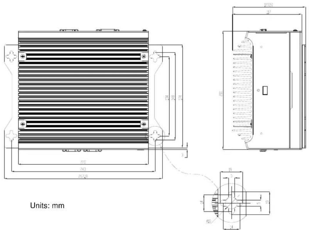
Figure 1.1 ARK-3440 Mechanical Dimensions Drawing
1.4.2 Weight
4.0 kg (8.8lb)
1.5 Power Requirements
1.5.1 System power
Minimum power input: DC 9 V \~ 34 V 9.0 A \~ 2.4 A
1.5.2 RTC battery
3 V / 195 mAH BR2032
1.6 Environmental Specifications
1.6.1 Operating temperature
■ With Industrial Grade CompactFlash disk: 0 \~ 50°C, with air flow
■ With 2.5" consumer grade HDD on internal HDD bay: 0 \~ 45°C, with air flow
1.6.2 Relative Humidity
95% @ 40°C (non-condensing)
1.6.3 Storage temperature
-40 \~ 85° C (-40 \~ 185° F)
1.6.4 Vibration loading during operation
■ With CompactFlash disk: 5 Grms, IEC 60068-2-64, random, 5 \~ 500 Hz, 1 Oct./min, 1 hr/axis.
■ With 2.5-inch hard disk: 1 Grms, IEC 60068-2-64, random, 5 \~ 500 Hz, 1 Oct./min, 1 hr/axis.
1.6.5 Shock during operation
■ With CompactFlash disk: 50 G, IEC 60068-2-27, half sine, 11 ms duration
■ With hard disk: 20 G, IEC 60068-2-27, half sine, 11 ms duration
1.6.6 Safety Certifications
UL, CCC, BSMI
1.6.7 EMC
CE, FCC, CCC, BSMI
Chapter 2
Hardware installation
This chapter introduces external IO and the installation of ARK-3440 Hardware.
2.1 I/O Locations
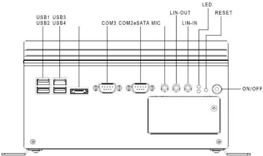
Figure 2.1 ARK-3440 Front View
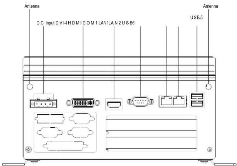
Figure 2.2 ARK-3440 Rear View
2.2 Front Panel Controls, Indicators, & Connectors
2.2.1 Power ON/OFF Button
ARK-3440 has a Power On/Off button with LED indicators on the front side that show On status (Green LED) and Off/Suspend status (Orange LED). The Power button supports dual functions: Soft Power -On/Off (Instant off or Delay 4 Seconds then off), and Suspend.
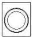
Figure 2.3 Power ON/OFF Button
2.2.2 Reset Button
ARK-3440 has a Reset button on the front panel. Press the button to activate the reset function.

Figure 2.4 Reset Button
2.2.3 LED Indicators
There are two LEDs on the front panel that indicate system status: The thermal LED is for system thermal alarm status; and HDD LED is for HDD and compact flash disk status.
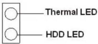
Figure 2.5 LED Indicators
2.2.4 Audio Connectors
ARK-3440 offers stereo audio ports by three phone jack connectors: Speaker Out, Line In, and Mic-In. Audio chip is ALC888, compliant with Azalea standard; the Speaker Out supports 3D surround stereo, with dual 2.2W amplifier.
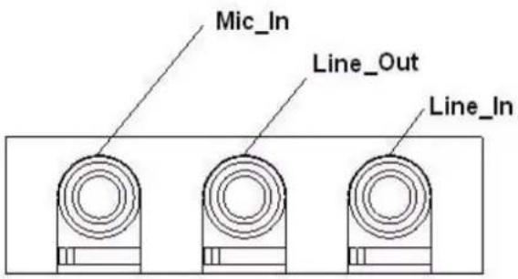
Figure 2.6 Audio jack connectors
2.2.5 COM Connector
ARK-3440 provides 6 D-sub 9-pin connectors that are serial communication interface ports. The COM1 on the rear panel supports RS-232/422/485 mode by BIOS selection; COM2 and 3 on the front panel and COM5 and 6 on the internal header only support RS-232. The COM1 and COM4 default settings are RS-232; if you want to use RS-422/485, make the change in BIOS setup.
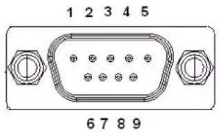
Figure 2.7 COM port connector
Table 2.1: COM standard serial port pin assignments
| RS-232 RS-422 RS-485 | ||||||||
| Pin Signal Name Signal Name Signal Name | ||||||||
| 1 | D | C | D | T | x | - | D | |
| 2 | R | x | D | T | x | + | ||
| 3 | TxD | Rx+ | NC | |||||
| 4 | D | T | R | Rx | - | NC | ||
| 5 | G | ND | G | N | D | G | ||
| 6 | DSR | NC | NC | |||||
| 7 | RTS | NC | NC | |||||
| 8 | CTS | NC | NC | |||||
| 9 | R | I | NC | NC | ||||
| Note: NC represents “No Connection”. | ||||||||
2.2.6 eSATA Connector
ARK-3440 has a 7-pin external connector for an eSATA device. It is fully compliant with SATA I/SATA II standards, and supports external SATA I/SATA II devices up to 300MB/sec.
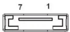
Figure 2.8 eSATA connector
2.2.7 USB Connector
ARK-3440 provides six USB connectors that give complete Plug & Play and hot swapping for up to 127 external devices. The USB interface complies with USB UHCI, Rev. 2.0 compliant. The USB interface can be disabled in the system BIOS setup. Please refer to Table. 2.2 For pin assignments.
The USB connectors are used for connecting any device that conforms to the USB standard, and many recent digital devices do. The USB interface supports Plug and Play, which enables you to connect or disconnect a device whenever you want, without turning off the computer.
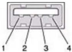
Figure 2.9 USB connector
Table 2.2: USB Connector
Pin Signal name Pin Signal name
| 1 VCC 2 USB_data- |
| 3 USB_data+ 4 GND |
2.2.8 Compact Flash Card
ARK-3440 is equipped with an external CF card. You can find the installation in Chapter 2.5.
2.3 Rear Panel I/O Connectors
2.3.1 Power Input Connector
ARK-3440 comes with a two-pin header that carries 9 \~ 34 V _DC external power input.
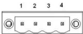
Figure 2.10 Power Input Connector
Table 2.3: Power connector pin assignments
| Pin Signal Name | |
| 1 | GND |
| 2 +9 ~ 34 V | DC |
| 3 +9 ~ 34 V | DC |
| 4 | GND |
2.3.2 Digital Visual Interface Connector (DVI-I)
The ARK-3440 offers an integrated D-sub 24-pin female DVI-I Digital Visual Interface connector; it carries integrated analog and digital video signals. This supports high-speed, high-resolution digital displays and traditional analog displays.
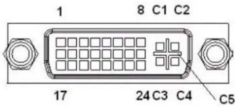
Figure 2.11 DVI-I Connector
Table 2.4: DVI-I Connector pin assignments
| Pin Signal Name Pin Signal Name | |||
| 1 TMDS Data 2- 2 TMDS Data 2+ | |||
| 3 TMDS Data 2/4 shield 4 TMDS Data 4- | |||
| 5 TMDS Data 4+ 6 DDC clock | |||
| 7 DDC data 8 Analog vertical sync | |||
| 9 TMDS Data 1- 10 TMDS Data 1+ | |||
| 11 TMDS Data 1/3 shield 12 TMDS Data 3- | |||
| 13 TMDS Data 3+ 14 +5 V | |||
| 15 Ground | 16 Hot plug detect | ||
| 17 TMDS data 0- | 18 TMDS data 0+ | ||
| 19 TMDS data 0/5 shield | 20 TMDS data 5- | ||
| 21 TMDS data 5+ | 22 TMDS clock shield | ||
| 23 TMDS clock+ | 24 TMDS clock- | ||
| C1 | Analog red | C2 | Analog green |
| C3 | Analog blue | C4 | Analog horizontal sync |
| C5 | Analog ground | ||
2.3.3 HDMI Connector
An integrated, 19-pin receptacle connector HDMI Type A Interface is provided. The HDMI link supports resolutions up to 1920x1200@60Hz.
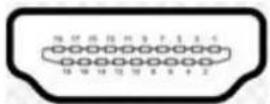
Figure 2.12 HDMI receptacle connector
Table 2.5: HDMI receptacle connector pin assignments
| Pin Signal Name Pin Signal Name | |||||
| 1 | T | M | D | S | D |
| 3 | T | M | D | S | D |
| 5 TMDS Data 1 shield 6 TMDS Data 1- | |||||
| 7 | T | M | D | S | D |
| 9 TTMDS Data 0- 10 TMDS Clock+ | |||||
| 11 | TMDS Clock shield | 12 TMDS Clock- | |||
| 13 CEC | 14 Reserved | ||||
| 15 SCL | 16 SDA | ||||
| 17 DDC/CEC Ground | 18 +5V | ||||
| 19 Hot Plug Detect | |||||
2.3.4 Ethernet Connector (LAN)
ARK-3440 provides two RJ45 connectors for Gigabit LAN interfaces; the board is equipped with Intel® 82577LM and 82583V Ethernet controllers that are fully compliant with IEEE 802.3u 10/100/1000 Mbps CSMA/CD standards. The Ethernet ports provide standard RJ-45 jack connectors with LED indicators that show Active/Link status (Green LED) and Speed status (Yellow LED).
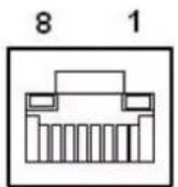
Figure 2.13 Ethernet connector
Table 2.6: RJ-45 Connector pin assignments
| Pin | 10/100/1000BaseT Signal Name |
| 1 | TX+ |
| 2 | TX- |
| 3 | RX+ |
| 4 | MDI2+ |
| 5 | MDI2- |
| 6 | RX- |
| 7 | MDI3+ |
| 8 | MDI3- |
2.3.5 LVDS Connector (Optional)
The ARK-3440 supports a D-Sub 26-pin connector that carries an LVDS signal output, and can direct-connect to LVDS LCD display via external cable. The system also provides jumper JP5 on the internal motherboard for selecting the LCD signal power of 5V or 3.3V; please refer to the jumper setting table A.4. The default setting is 3.3V.
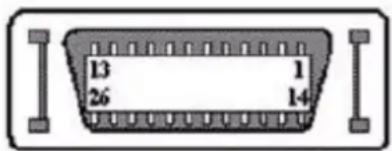
Figure 2.14 LVDS Connector (optional)
Table 2.7: LVDS Connector Pin Assignment
| Pin | Signal Name | Pin | Signal name | |
| 1 | LVDS_CLKBP | 14 | LVDS_CLKBM | |
| 2 | GND 15 | LVDS_YAM0 | ||
| 3 | LVDS_YAP0 | 16 | LVDS_YAM1 | |
| 4 | LVDS_YAP1 | 17 | LVDS_YAM2 | |
| 5 | LVDS_YAP2 | 18 | LVDS_CLKAM | |
| 6 | LVDS_CLKAP | 19 | GND | |
| 7 | +3.3 or +5 V | 20 | +3.3 or +5 V | |
| 8 | GND 21 | LVDS_YAM3 | ||
| 9 | LVDS_YAP3 | 22 | LVDS_YBM0 | |
| 10 | LVDS_YBP0 | 23 | LVDS_YBM1 | |
| 11 | LVDS_YBP1 | 24 | LVDS_YBM2 | |
| 12 | LVDS_YBP2 | 25 | LVDS_YBM3 | |
| 13 | LVDS_YBP3 | 26 | GND |
2.3.6 LCD Backlight On/Off control Connector (Optional)
The ARK-3440 supports a D-sub 9-pin connector which provides BKLTEN signal as well as +12 V, +5 V and Ground Pin signals that allow the user to connect these signals to an LCD inverter to implement the LCD On/Off control.
■ Provides BKLTEN signal that inverter module requires for inverter on/off control.
- Provides +12 V, +5 V to serve as the inverter power source. The additional VBR signal pin may be connected to the LCD inverter to allow the user to achieve brightness adjustment through customer's software utility.
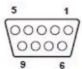
Figure 2.15 LCD Backlight connector (optional)
Table 2.8: LCD Backlight Connector Pin Assignment
| Pin | Signal | name | Pin | Signal |
| 1 +12 V 6 Reserved | ||||
| 2 GND 7 Reserved | ||||
| 3 BKLTEN 8 Reserved | ||||
| 4 VBR 9 Reserved | ||||
| 5 | + | 5 | V | |
2.3.7 LPT Connector (Optional)
The ARK-3440 supports one D-sub 25-pin female connector, which can serve as a printer or other communications interface port. Pin assignments are as follows.
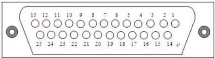
Table 2.9: LPT Connector Pin Assignment
| Pin | Signal Name | Pin | Signal name |
| 1 | STROBE | 14 | ALF |
| 2 | PD0 | 15 | ERROR |
| 3 | PD1 | 16 | INIT |
| 4 | PD2 | 17 | SLCTIN |
| 5 | PD3 | 18 | GND |
| 6 | PD4 | 19 | GND |
| 7 | PD5 | 20 | GND |
| 8 | PD6 | 21 | GND |
| 9 | PD7 | 22 | GND |
| 10 | ACK | 23 | GND |
| 11 | BUSY | 24 | GND |
| 12 | PE | 25 | GND |
| 13 | SLCT |
2.3.8 DIO Connector (Optional)
The ARK-3440 supports one D-sub 25-pin male connector, which can serve as a digital I/O communication interface port. Pin assignments below.
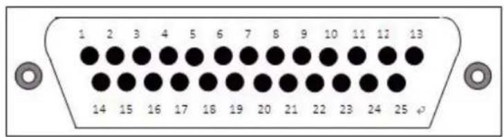
Figure 2.17 DIO Connector (optional)
Table 2.10: DIO Connector Pin Assignment
| Pin Signal Name Pin Signal name | ||||
| 1 DIO0-0 14 DIO1-0 | ||||
| 2 | DIO0-1 | 15 | DIO1-1 | |
| 3 | DIO0-2 | 16 | DIO1-2 | |
| 4 | DIO0-3 | 17 | DIO1-3 | |
| 5 | DIO0-4 | 18 | DIO1-4 | |
| 6 | DIO0-5 | 19 | DIO1-5 | |
| 7 DIO0-6 20 DIO1-6 | ||||
| 8 DIO0-7 21 DIO1-7 | ||||
| 9 G | N | D | 2 | 2 |
| 10 GND 23 GND | ||||
| 11 | GND | 24 | GND | |
| 12 +5 V 25 +5 V | ||||
| 13 +5 V | ||||
2.4 Memory Installation
- Remove the top screws and top cover.
- Remove two screws and memory heatspreader.
- Insert the memory module into the SODIMM socket. If only one memory module is being installed, always install it into CN12.
- Reinstall heatspreader and top cover.
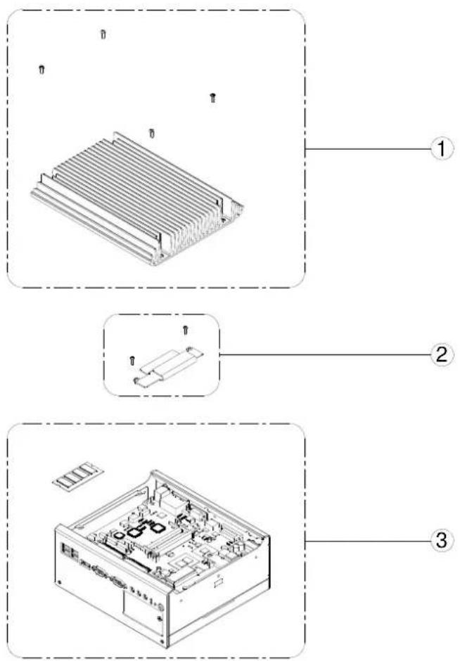
Figure 2.18 Memory Installation
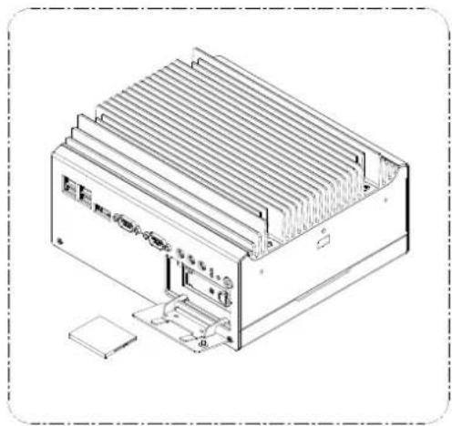
2.5 Compact Flash Installation
-
Open the front CF/HDD door by loosening the door screw.
-
Insert the CF card into the CF socket, then reassemble.
natural_image
Technical line drawing of an electronic device with cooling fins and a cooling unit (no text or symbols)Figure 2.19 CF Card Installation
2.6 HDD Installation
2.6.1 Internal fixed HDD installation
-
Remove the bottom cover by unscrewing the 4 screws
-
Install the 2.5" SATA HDD with the 4 HDD mounting screws. Make sure the PCB side of the HDD will be facing the bottom cover.
-
Connect the SATA signal cable and power cable to the HDD.
-
Remove the protecting sheet of the HDD thermal pad, attach it onto the bottom cover.
-
Reinstall the bottom cover.
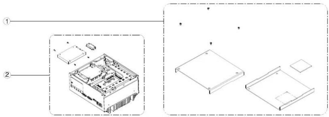
Figure 2.20 Internal Fixed HDD Installation
2.6.2 Removable 2.5" Storage Device Installation
- It is recommended to use 2.5" SATA solid state device on the removable bay.
- Open the front CF/HDD door by loosening the door screw.
- Attach the 2.5" SATA storage device to the loader with 4 HDD mounting screws
- Slide HDD loader along the rails to the end and fix the lever screw. Re-fix the front CF/HDD door.
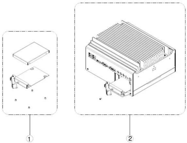
Figure 2.21 Removable 2.5" Storage Device Installation
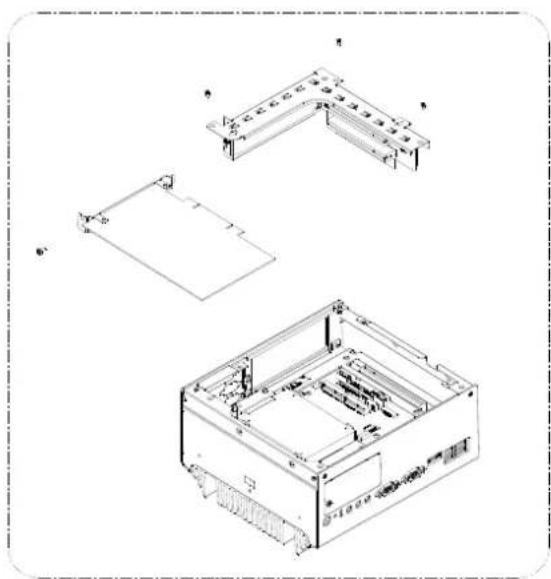
2.7 PCI card installation
- Remove the 4 bottom screws and the bottom cover.
- Remove the rser card module.
- Insert the PCI extension card into the PCI slot of the riser card module.
- Replace the riser card module.
- Reassemble the bottom cover.
natural_image
Technical line drawing of a mechanical or electronic device with three views: top, front, and side (no text or symbols present)Figure 2.22 PCI Card Installation
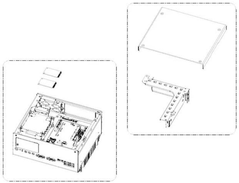
2.8 Mini PCIe Installation
-
Open the bottom cover and remove the riser card module. (Refer Chapter 2.4)
-
Insert the Mini PCIe card into the Mini PCIe socket and latch into place.
natural_image
Technical line drawings of an internal computer chassis and a rectangular device (no text or symbols)Figure 2.23 Mini PCI Card Installation
2.9 Antenna Installation
-
Remove the top heatsink by loosening the four screws. (See Section 2.4.)
-
Pass the internal antenna cable jack through the antenna hole in the rear panel and fix it in place by tightening the matching nut.
-
Attach the external antenna cable, and reassemble the top heatsink.
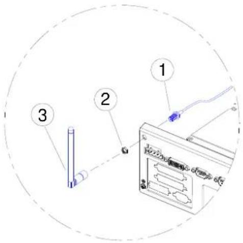
Figure 2.24 Antenna Installation
2.10 Optional Cable Installation
Open the bottom cover and follow the illustration and table below for optional cable installations and connections.
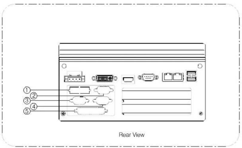
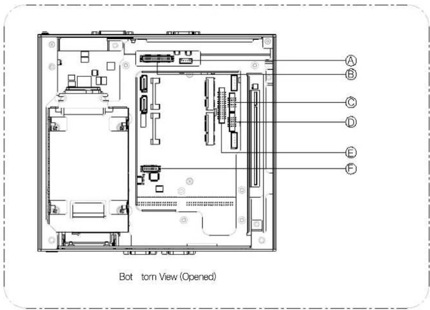
Figure 2.25 Optional Cable Installation
| Rear Panel Connector Internal Connector | |
| LVDS power cable (P/N:1700009396)* 1 A | |
| LVDS cable (P/N:1700009398) 2 B | |
| COM5 cable (P/N:1700008871) 3 C | |
| COM6 cable (P/N:1700008871) 4 D | |
| LPT cable (P/N:1700018187) 5 E | |
| DIO cable (P/N:1700018448) 5 F | |
Note! When the LVDS panel power is provided from the system, the LVDS voltage jumper (JP5) needs to be configured.

2.11 CPU Thermal Grease Pad
CPU thermal grease pad is one of the key components of ARK-3440 thermal design. Always use the grease pad provided by Advantech. The P/N of the grease pad is :
Part Number Description
1990020828N001
Thermal-Pad D27*0.25 K=3 TP HW-PCM45Fφ27*0.25
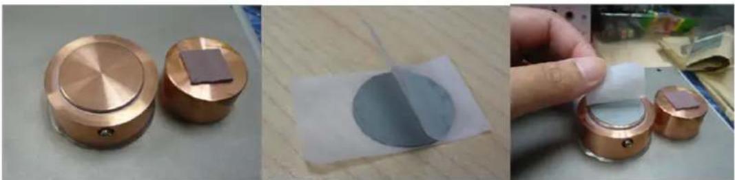
To ensure the best thermal performance, it is recommended to replace the thermal grease for CPU thermal pole each time the top cover is opened.
-
To replace the thermal grease, clean up the CPU thermal pole by using paper tissue or soft cloth. DO NOT USE any kind of solvent to clean the thermal pole as this may damage the thermal grease inside the thermal pole.
-
Gently remove one of the protect paper of the grease pad and apply the grease to the CPU thermal pole. Press onto the grease pad for 30 seconds, then remove the protect paper gently from the grease pad.
natural_image
Three-panel image showing copper-colored circular components with square bases, a close-up of a circular sample, and a hand holding a transparent container (no visible text or symbols)Chapter 3
BIOS settings
This chapter introduces how to set BIOS configurations.
3.1 BIOS Introduction
Advantech provides a current version of the full-featured AMI BIOS that has been integrated into many motherboards for over a decade. With the AMI BIOS Setup program, users can modify BIOS settings and control various system features. This chapter describes the basic navigation of the ARK-3440 BIOS setup screens.
| Main Advanced Chipset Boot Security Save & Exit | |
| BIOS Information BIOS Vendor American Megatrends Core Version 4.6.3.7 Project Version 1ABPZ 0.15 x64 Bios Version ARK3440 V1.18 EC Version 0100 Build Date 02/23/2012 18:13:33 | Choose the system default language |
| Memory Information Total Memory 4096 MB (DDR3 1066) | |
| System Language [English] | |
| System Date [Sat 02/06/2010] System Time [21:55:19] | +: Select Screen ↑↓: Select Item Enter: Select +/-: Change Opt. F1: General Help F2: Previous Values F3: Optimized Defaults F4: Save ESC: Exit |
| Access Level Administrator | |
| Version 2.00.1201, Copyright (C) 2009 American Megatrends, Inc. | |
AMI's BIOS ROM has a built-in Setup program that allows users to modify the basic system configuration. This information is stored in NVRAM area so it retains the Setup information when the power is turned off.
3.2 Entering BIOS Setup
Turn on the computer and check for the "patch code". If there is a number assigned to the patch code, the on-board CPU is supported by the current BIOS. If there is no number assigned to the patch code, please contact an Advantech application engineer to obtain an up-to-date patch code file, to ensure the system status of CPU is valid. Then press
3.2.1 Main Setup
When users first enter the BIOS Setup Utility, they enter the Main setup screen. Users can always return to the Main setup screen by selecting the Main tab. There are two Main Setup options. They are described in this section. The Main BIOS Setup screen is shown below.
![Aptio Setup Utility - Copyright (C) 2009 American Megatrends, Inc. Main Advanced Chipset Boot Security Save & Exit BIOS Information BIOS Vendor American Megatrends Core Version 4.6.3.7 Project Version 1ABPZ 0.15 x64 Bios Version ARK3440 V1.18 EC Version 0100 Build Date 02/23/2012 18:13:33 Memory Information Total Memory 4096 MB (DDR3 1066) System Language [English] System Date [Sat 02/06/2010] System Time [21:55:19] Access Level Administrator Choose the system default language ++: Select Screen ↑↓: Select Item Enter: Select +/-: Change Opt. F1: General Help F2: Previous Values F3: Optimized Defaults F4: Save ESC: Exit Version 2.00.1201. Copyright (C) 2009 American Megatrends, Inc.](/content/2026/05/921598/images/9ef5799b3540ca31b2c33319c6a295161b61eb8a6849923298ee4638ea456b38.jpg)
Figure 3.1 The Main BIOS setup screen
The Main BIOS setup screen has two main frames. The left frame displays all the options that can be configured. Grayed-out options cannot be configured; options in blue can. The right frame displays the key legend.
Above the key legend is an area reserved for a text message. When an option is selected in the left frame, it is highlighted in white. Often a text message will accompany it.
■ System Date / System Time
Use this option to change the system time and date. Highlight System Time or System Date using the
3.3 Advanced BIOS Features Setup
Select the Advanced tab from the ARK-3440 setup screen to enter the Advanced BIOS Setup screen. Users can select any item in the left frame of the screen, such as PCI Configuration, to go to the sub menu for that item. Users can display an Advanced BIOS Setup option by highlighting it using the
![Aptio Setup Utility - Copyright (C) 2009 American Megatrends, Inc. Main Advanced Chipset Boot Security Save & Exit Legacy OpROM Support Launch PXE OpROM [Disabled] Launch Storage OpROM [Enabled] PCI Subsystem Settings ACPI Settings S5 RTC Wake Settings CPU Configuration SATA Configuration Intel IGO SWSCI OpRegion Intel TDT(AT-p) Configurations Intel TXT(LT) Configuration USB Configuration Super IO Configuration ARK3440 FEATURES Serial Port Console Redirection Enable or Disable Boot Option for Legacy Network Devices. +: Select Screen ↑: Select Item Enter: Select +/-: Change Opt. F1: General Help F2: Previous Values F3: Optimized Defaults F4: Save ESC: Exit Version 2.00.1201. Copyright (C) 2009 American Megatrends, Inc.](/content/2026/05/921598/images/e08b3b2e2986a92b1bd667c19c4a80574f72d56554ef0755b96dc66151167492.jpg)
Figure 3.2 The Advanced BIOS setup screen
■ Legacy OpROM Support
■ Launch PXE OpROM: Enable or Disable Boot Option for Legacy Network Devices.
Disabled [Default]
Enabled
■ Launch Storage OpROM: Enable or Disable Boot Option for Legacy Mass Storage Devices with Option ROM.
Disabled
Enabled [Default]
PCI Subsystem Settings
- PCI Bus Driver Version
- PCI ROM Priority: Specifies what PCI Option ROM to launch.
Legacy ROM
EFI Compatible ROM [Default]
- PCI Common Settings
PCI Latency Timer: Value to be programmed into PCI Latency Timer Register.
32 PCI Bus Clocks [Default]
64 PCI Bus Clocks
96 PCI Bus Clocks
128 PCI Bus Clocks
160 PCI Bus Clocks
192 PCI Bus Clocks
224 PCI Bus Clocks
248 PCI Bus Clocks
- VGA Palette Snoop: Enables or Disables VGA Palette Register Snooping.
Disabled [Default]
Enabled
ACPI Settings
- Enable ACPI Auto Configuration: Enables or Disables BIOS ACPI Auto Configuration.
Disabled [Default]
Enabled
- Enable Hibernation: Enables or Disables System ability to hibernate (OS/S4 Sleep State). This option may be not effective with some OSs.
Disabled [Default]
Enabled
- ACPI Sleep State: Select the highest ACPI sleep state the system will enter, when the SUSPEND button is pressed.
Suspend Disabled
S1 (CPU Stop Clock)
S3 (Suspend to RAM) [Default]
S5 RTC Wake Settings: Enable system to wake from S5 using RTC alarm.
Wake system with Fixed Time: Enable or disable System wake on alarm event. When enabled, System will wake on the hr::min::sec specified.
Disabled [Default]
Enabled
- Wake system with Dynamic Time: Enable or disable System wake on alarm event. When enabled, System will wake on the current time + Increase minute(s).
Disabled [Default]
Enabled
■ CPU Configuration: CPU Configuration Parameters.
| CPU Configuration | Enable the power management features. | |
| Processor Type | Intel(R) Core(TM) i7 CPU | |
| EMT64 | Supported | |
| Processor Speed | 1862 MHz | |
| Processor Stepping | 20655 | |
| Microcode Revision | 2 | |
| Processor Cores | 2 | |
| Intel HT Technology | Supported | |
| Hyper-threading | [Enabled] | |
| Active Processor Cores | [All] | |
| Limit CPUID Maximum | [Disabled] | |
| Hardware Prefetcher | [Enabled] | |
| Adjacent Cache Line Prefetch | [Enabled] | |
| Intel Virtualization Technology | [Disabled] | |
| Power Technology | [Custom] | |
| EIST | [Enabled] | |
| P-STATE Coordination | [HW_ALL] | |
| CPU C3 Report | [Disabled] | |
| CPU C6 report | [Enabled] | |
| Package C State limit | [No Limit] | |
- Hyper-threading: Enabled for Windows XP and Linux (OS optimized for Hyper-Threading Technology) and Disabled for other OS (OS not optimized for Hyper-Threading Technology). When Disabled only one thread per enabled core is enabled.
Disabled
Enabled [Default]
- Active Processor Cores: Number of cores to enable in each processor package.
All [Default]
1
2
- Limit CPUID Maximum: Disabled for Windows XP.
Disabled [Default]
Enabled
– Hardware Prefetcher: To turn on/off the MLC streamer prefetcher.
Disabled
Enabled [Default]
- Adjacent Cache Line Prefetch: To turn on/off prefetching of adjacent cache lines.
Disabled
Enabled [Default]
- Intel Virtualization Technology: When enabled, a VMM can utilize the additional hardware capabilities provided by Vander pool Technology.
Disabled [Default]
Enabled
– Power Technology: Enable the power management features.
Disable
Energy Efficient
Custom [Default]
- TDC Limit: Turbo-XE Mode Processor TDC Limit in 1/8 A granularity. 0 means using the factory-configured value.
- TDP Limit: Turbo-XE Mode Processor TDP Limit in 1/8 W granularity. 0 means using the factory-configured value.
■ SATA Configuration: SATA Devices Configuration.
SATA Mode: 1) IDE Mode. (2) AHCI Mode. (3) RAID Mode.
Disable
IDE Mode [Default]
AHCI Mode
RAID Mode
- Serial-ATA Controller 0: Enable / Disable Serial ATA Controller 0.
Disable
Enhanced
Compatible [Default]
Intel IGD SWSCI OpRegion: Intel IGD SWSCI OpRegion Function.
- DVMT/FIXED Memory: Select DVMT/FIXED Mode Memory size used by Internal Graphics Device.
128MB
256MB [Default]
Maximum
- IGD - Boot Type: Select the Video Device which will be activated during POST. This has no effect if external graphics present.
VBIOS Default
CRT
LVDS
CRT + LVDS
DVI
HDMI
CRT + DVI [Default]
- LCD Panel Type: Select LCD panel used by Internal Graphics Device by selecting the appropriate setup item.
VBIOS Default [Default]
640x480 LVDS
800x600 LVDS
1024x768 LVDS
1280x1024 LVDS
1400x1050 LVDS
1600x1200 LVDS
1280x768 LVDS
1680x1050 LVDS
1920x1200 LVDS
1600x900 LVDS
1280x800 LVDS
1280x600 LVDS
2048x1536 LVDS
- Panel Scaling: Select the LCD panel scaling option used by the Internal Graphics Device.
Auto [Default]
Force Scaling
Off
Maintain Aspect Ratio
- Backlight Control: Back Light Control Setting.
PWM Inverted [Default]
PWM Normal
GMBus Inverted
GMBus Normal
- BIA Control
VBIOS Default [Default]
Disabled
Level 1
Level 2
Level 3
Level 4
Level 5
- Spread Spectrum clock Chip: Hardware: Spread is controlled by chip; Software: Spread is controlled by BIOS.
Off [Default]
Hardware
Software
- ALS Support: Valid only for ACPI. Legacy = ALS Support through the IGD INT10 function. ACPI = ALS support through an ACPI ALS driver.
Enabled
Disabled [Default]
- Gfx Low Power Mode: This option is applicable for SFF only.
Enabled
Disabled [Default]
Active LFP: Select the Active LFP Configuration. No LVDS/VBIOS: does not enable LVDS. Int-LVDS: VBIOS enables LVDS driver by integrated encoder. SDVO LVDS: VBIOS enables LVDS driver by SDVO encoder. eDP / LVDS: Driven by Int-DisplayPort encoder.
No LVDS
Int-LVDS [Default]
SDVO LVDS
eDP Port-A
eDP Port-D
- Panel Color Depth: Select the LFP Panel Color Depth.
18 Bit
24 Bit
Intel TDT(AT-p) Configurations: Disabling TDT allows user to login to platform. This is strictly for testing only. This does not disable TDT Services in ME.
– Intel Theft Deterrence Technology Configuration: Enable/Disable TDT in BIOS for testing only.
- TDT: Enable/Disable TDT in BIOS for testing only.
Disabled [Default]
Enabled
Intel TXT(LT) Configuration: Intel Trusted Execution Technology
Intel TXT(LT) Support
Disabled [Default]
Enabled
USB Configuration: USB Configuration Parameters
- Legacy USB Support: Enables Legacy USB support. AUTO option disables legacy support if no USB devices are connected. DISABLE option will keep USB devices available only for EFI applications.
Enabled [Default]
Disabled
Auto
- EHCl Hand-off: This is a workaround for OSes without EHCl hand-off support. The EHCl ownership change should be claimed by EHCl driver.
Disabled
Enabled [Default]
- Device Reset timeout: USB mass storage device Start Unit command timeout.
10 sec
20 sec [Default]
30 sec
40 sec
- Device Reset timeout: USB mass storage device Start Unit command timeout.
10 sec
20 sec [Default]
30 sec
40 sec
- USB 2.0 USB Flash Drive 0.00: Mass storage device emulation type.
'AUTO' enumerates devices according to their media format. Optical drives are emulated as 'CDROM', drives with no media will be emulated according to a drive type.
Auto [Default]
Floppy
Forced FDD
Hard Disk
CD-ROM
■ Super IO Configuration: System Super IO Chip Parameters.
– Parallel Port Configuration: Set Parameters of Parallel Port (LPT/LPTE)
- Parallel Port: Enable or Disable Parallel Port (LPT/LPTE)
Disabled
Enabled [Default]
- Change Settings: Select optimal settings for Super IO Device.
Auto [Default]
IO=378h; IRQ=5;
IO=378h; IRQ=3,4,5,6,7,10,11,12;
IO=278h; IRQ=3,4,5,6,7,10,11,12;
IO=3BCh; IRQ=3,4,5,6,7,10,11,12;
IO=378h;
IO=278h;
IO=3BCh;
– Device Mode: Change the Printer Port mode.
STD Printer Mode [Default]
SPP Mode
EPP-1.9 and SPP Mode
EPP-1.7 and SPP Mode
ECP Mode
ECP and EPP 1.9 Mode
ECP and EPP 1.7 Mode
■ ARK-3440 FEATURES: CRB Board Parameters
- COM1 MODE: COM SPEED RS232/422/485 MODE.
RS232 [Default]
RS422
RS485
- COM4 MODE: COM SPEED RS232/422/485 MODE.
RS232 [Default]
RS422
RS485
- 82577 LAN SWITCH: LAN Enable/Disable.
DISABLED
ENABLED [Default]
- 82583 LAN SWITCH: LAN Enable/Disable.
DISABLED
ENABLED [Default]
Serial Port Console Redirection: Serial Port Console Redirection.
- Console Redirection: Console Redirection Enable/Disable.
DISABLED
ENABLED [Default]
- Terminal Type: VT-UTF8 is the preferred terminal type for out-of-band management. The next best choice is VT100+ and then VT100. See above, in Console Redirection Settings page, for more Help with Terminal Type/Emulation.
VT100
VT100+
VT-UTF8 [Default]
ANSI
3.4 Chipset BIOS Feature Setup
Select the Chipset tab from the ARK-3440 setup screen to enter the Chipset BIOS Setup screen. Users can select any item in the left frame of the screen, such as PCI Configuration, to go to the sub menu for that item. Users can display a Chipset BIOS Setup option by highlighting it using the
![Aptio Setup Utility - Copyright (C) 2009 American Megatrends, Inc. Main Advanced Chipset Boot Security Save & Exit Enable CRID [Disabled] ► North Bridge ► South Bridge Enable Compatible Revision ID +: Select Screen ↑↓: Select Item Enter: Select +/-: Change Opt. F1: General Help F2: Previous Values F3: Optimized Defaults F4: Save ESC: Exit Version 2.00.1201. Copyright (C) 2009 American Megatrends, Inc.](/content/2026/05/921598/images/14f4b2e675814b4d6f4e31cde97c9bfb0b5b9d3d0c54efcac31ecd5a3e8a2750.jpg)
Figure 3.3 The Chipset BIOS setup screen
■ Enable CRID: Enable Compatible Revision ID.
Disabled [Default]
Enabled
North Bridge: North Bridge Parameters.
– Low MMIO Align: Low MMIO resources align at 64MB/1024MB.
64M [Default]
1024M
- Initiate Graphic Adapter: Select which graphics controller to use as the primary boot device.
IGD
PCI/IGD
PCI/PEG
PEG/IGD [Default]
PEG/PCI
- VT-d: VT-d Enable/Disable.
Disabled [Default]
Enabled
- PCI Express Compliance Mode: PCI Express Compliance Testing Mode.
Disabled [Default]
Enabled
- PCI Express Port: PCI Express.
Disabled
Enabled
Auto [Default]
- IGD Memory: IGD Share Memory Size.
Disabled
32M [Default]
64M
128M
- PAVP Mode: Select PAVP Mode used by Internal Graphics Device.
Disabled [Default]
Enabled
- PEG Force Gen1: PCI Express Port Force Gen1.
Disabled [Default]
Enabled
■ South Bridge: South Bridge Parameters.
– SMBus Controller: SMBus Controller Help.
Disabled
Enabled [Default]
– GbE Controller: GbE Controller help.
Disabled
Enabled [Default]
– Wake on Lan from S5: Wake on Lan from S5 help.
Disabled [Default]
Enabled
- Restore AC Power Loss: Restore AC Power Loss help.
Power Off [Default]
Power On
Last State
- SLP_S4 Assertion Stretch Enable: Select a minimum assertion width of the SLP_S4# signal.
Disable
Enable [Default]
- SLP_S4 Assertion Width: SLP_S4 Assertion Width help.
1-2 Seconds
2-3 Seconds
3-4 Seconds
4-5 Seconds [Default]
– Azalia HD Audio: Enable / Disable Azalia HD Audio.
Disabled
Enabled [Default]
- Azalia internal HDMI codec: Enable/Disable internal HDMI codec for Azalia.
Disabled [Default]
Enabled
- High Precision Timer: Enable or Disable the High Precision Event Timer.
Disabled
Enabled [Default]
- PCI Express Ports Configuration: PCI Express Ports Configuration
- PCI Express Port 1: Enable or Disable the PCI Express Ports in the Chipset.
Disabled
Enabled
Auto [Default]
- PCI Express Port2: Enable or Disable the PCI Express Ports in the Chipset.
Disabled
Enabled
Auto [Default]
- PCI Express Port 3: Enable or Disable the PCI Express Ports in the Chipset.
Disabled
Enabled
Auto [Default]
- PCI Express Port 4: Enable or Disable the PCI Express Ports in the Chipset.
Disabled
Enabled
Auto [Default]
- PCI Express Port 5: Enable or Disable the PCI Express Ports in the Chipset.
Disabled
Enabled
Auto [Default]
- PCI Express Port 6: Enable or Disable the PCI Express Ports in the Chipset.
Disabled
Enabled
Auto [Default]
- PCI Express Port 7: Enable or Disable the PCI Express Ports in the Chipset.
Disabled
Enabled
Auto [Default]
- PCI Express Port 8: Enable or Disable the PCI Express Ports in the Chipset.
Disabled
Enabled
Auto [Default]
- USB Configuration: USB Configuration - All USB Devices: Enable / Disable All USB Devices. Disabled Enabled [Default]
- EHCI Controller 1: Enable / Disable USB 2.0 (EHCI) Support. Disabled Enabled [Default]
– EHCI Controller 2: Enable / Disable USB 2.0 (EHCI) Support.
Disabled
Enabled [Default]
- RMH Support: Enable / Disable RMH Support; AUTO: Only Enable RMH support on Ibex Peak B0 Stepping.
Disabled
Enabled
Auto [Default]
- USB Port 0: Enable / Disable USB Port 0.
Disabled
Enabled [Default]
- USB Port 1: Enable / Disable USB Port 1.
Disabled
Enabled [Default]
- USB Port 2: Enable / Disable USB Port 2.
Disabled
Enabled [Default]
- USB Port 3: Enable / Disable USB Port 3.
Disabled
Enabled [Default]
- USB Port 4: Enable / Disable USB Port 4.
Disabled
Enabled [Default]
- USB Port 5: Enable / Disable USB Port 5.
Disabled
Enabled [Default]
- USB Port 6: Enable / Disable USB Port 6.
Disabled
Enabled [Default]
- USB Port 7: Enable / Disable USB Port 7.
Disabled
Enabled [Default]
- USB Port 8: Enable / Disable USB Port 8.
Disabled
Enabled [Default]
- USB Port 9: Enable / Disable USB Port 9.
Disabled
Enabled [Default]
- USB Port 10: Enable / Disable USB Port 10.
Disabled
Enabled [Default]
- USB Port 11: Enable / Disable USB Port 11.
Disabled
Enabled [Default]
3.5 Boot BIOS Feature Setup
Select the BOOT tab from the setup screen to enter the BOOT BIOS Setup screen. Users can select any item in the left frame of the screen, such as PCI Configuration, to go to the sub menu for that item. Users can display a BOOT BIOS Setup option by highlighting it using the
![Aptio Setup Utility - Copyright (C) 2009 American Megatrends, Inc. Main Advanced Chipset Boot Security Save & Exit Boot Configuration Quiet Boot [Disabled] Fast Boot [Disabled] Setup Prompt Timeout 1 Bootup NumLock State [On] CSM16 Module Verison 07.60 GateA20 Active [Upon Request] Option ROM Messages [Force BIOS] Interrupt 19 Capture [Disabled] Boot Option Priorities Boot Option #1 [USB 2.0 Flash Di...] Boot Option #2 [Built-in EFI Shell] Boot Option #3 [UEFI: USB 2.0 F1...] Hard Drive BBS Priorities Enables/Disables Quiet Boot option +: Select Screen T1: Select Item Enter: Select +/-: Change Opt. F1: General Help F2: Previous Values F3: Optimized Defaults F4: Save ESC: Exit Version 2.00.1201. Copyright (C) 2009 American Megatrends, Inc.](/content/2026/05/921598/images/0122b2ff5d9b66fed97802b5e4327e9158fa1e83de88a9ce8b6d9512950d6682.jpg)
Figure 3.4 The Chipset BIOS setup screen
■ Quiet Boot: Enables/Disables Quiet Boot option.
Disabled [Default]
Enabled
■ Fast Boot: Enables/Disables boot with initialization of a minimal set of devices required to launch active boot option. Has no effect for BBS boot options.
Disabled
Enabled [Default]
■ Bootup NumLock State: Select the keyboard NumLock state.
On [Default]
Off
GateA20 Active: UPON REQUEST - GA20 can be disabled using BIOS services. ALWAYS - do not allow disabling GA20; this option is useful when any RT code is executed above 1MB.
Upon Request [Default]
Always
Option ROM Messages: Set display mode for Option ROM.
Force BIOS [Default]
Keep Current
Interrupt 19 Capture: Enabled: Allows Option ROMs to trap Int 19.
Disabled [Default]
Enabled
■ Boot Option Priorities: Sets the system boot order.
- Hard Drive BBS Priorities: Sets the order of the legacy devices in this group.
3.6 Security BIOS Feature Setup
Select the BOOT tab from the ARK-3440 setup screen to enter the Security BIOS Setup screen. Users can select any item in the left frame of the screen. Users can display a Security BIOS Setup option by highlighting it using the
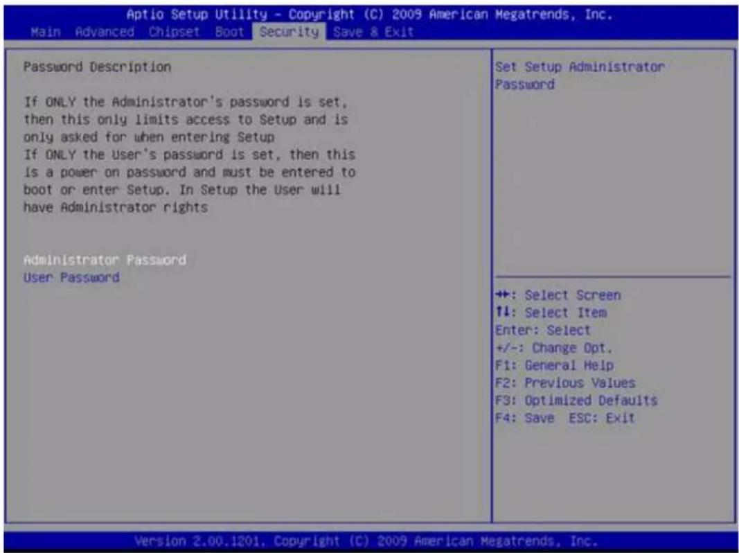
Figure 3.5 The Security BIOS setup screen
■ Administrator Password: Set up Administrator Password. When set, limits access to BIOS Setup.
■ User Password: Set User Password. When set, limits machine boot and access to BIOS Setup.
3.7 Save & Exit BIOS Feature Setup
Select the BOOT tab from the ARK-3440 setup screen to enter the save BIOS Setup screen. Users can select any item in the left frame of the screen. Users can display a save BIOS Setup option by highlighting it using the
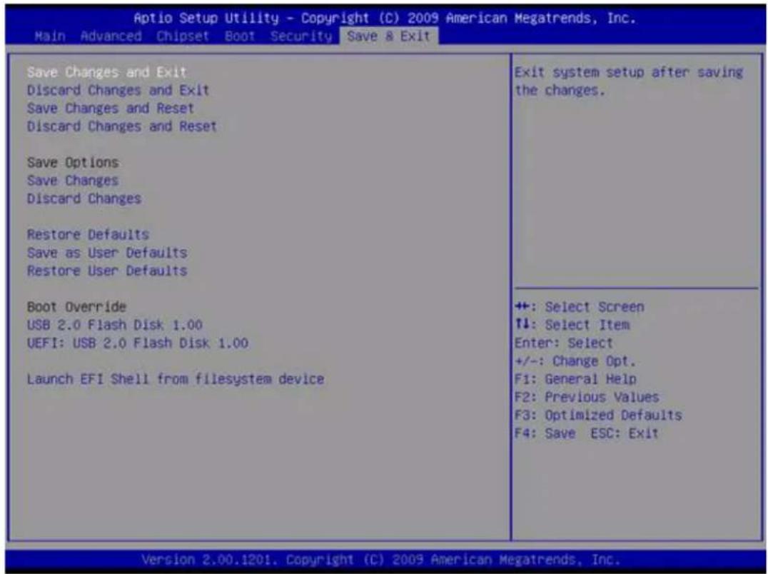
Figure 3.6 The Save & Exit BIOS setup screen
■ Save Changes and Exit: Exit system setup after saving the changes.
Save configuration and exit?
Yes [Default]
No
- Discard Changes and Exit: Exit system setup without saving any changes.
Quit without saving?
Yes [Default]
No
■ Save Changes and Reset: Reset the system after saving the changes.
Save configuration and reset?
Yes [Default]
No
- Discard Changes and Reset: Reset system setup without saving any changes.
Reset without saving?
Yes [Default]
No
■ Save Changes: Save Changes done so far to any of the setup options.
Save configuration?
Yes [Default]
No
- Discard Changes: Discard Changes done so far to any of the setup options.
Load Previous Values?
Yes [Default]
No
- Restore Defaults: Restore/Load Defaults values for all the setup options.
Load Optimized Defaults?
Yes [Default]
No
■ Save as User Defaults: Save the changes done so far as User Defaults.
Save configuration?
Yes [Default]
No
- Restore User Defaults: Restore the User Defaults to all the setup options.
Restore User Defaults?
Yes [Default]
No
- Restore User Defaults: Restore the User Defaults to all the setup options.
Restore User Defaults?
Yes [Default]
No
Appendix A
Function Settings
A.1 Function Setting
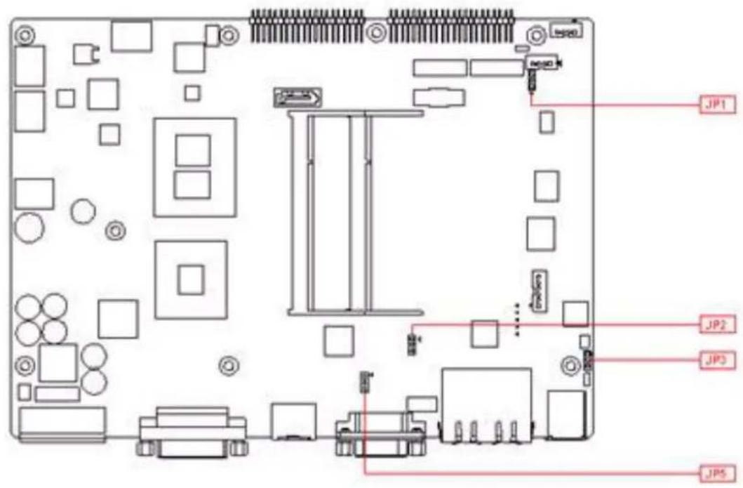
Figure A.1 Top View
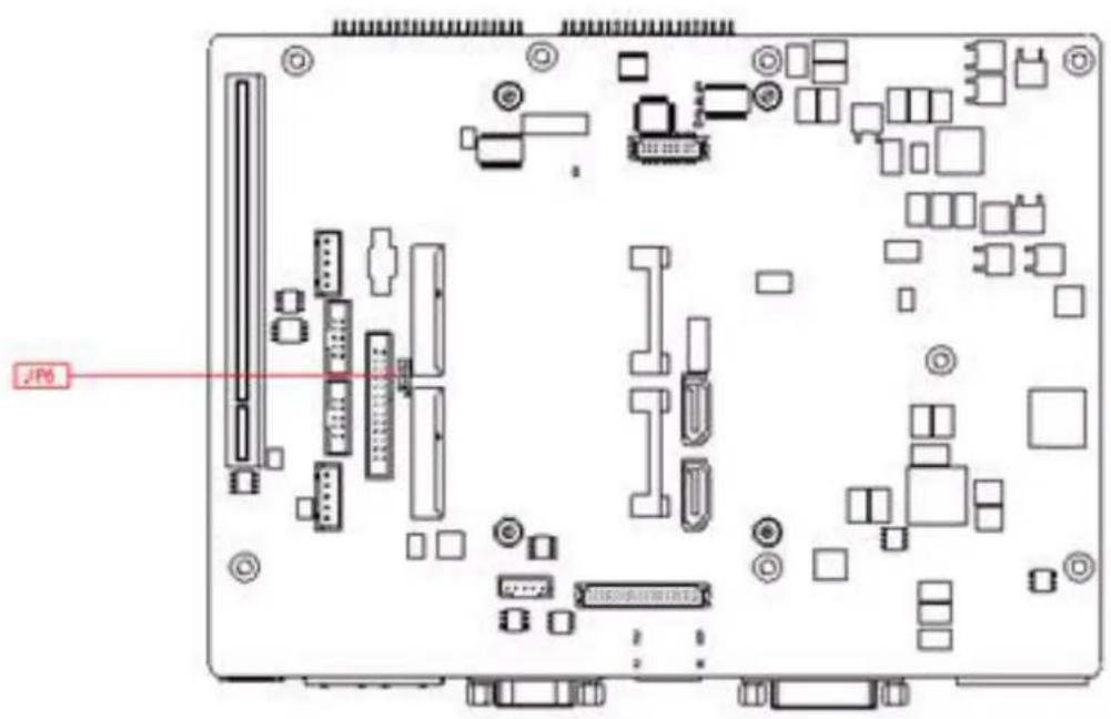
Figure A.2 Bottom View
Table A.1: ATX / AT Mode switch
| JP1 ATX / AT Mode switch |
| Footprint 3x1 Pin |
| Setting Function |
| (1-2) AT |
| (2-3) ATX Mode (default) |
Table A.2: PCI Express mini card version select
| JP2 / JP6 mini PCI Express mini card version select |
| Footprint 3x1 Pin |
| Setting Function |
| (1-2) Ver. 1.2(default) |
| (2-3) Ver. 1.1 |
Table A.3: Clear CMOS
| JP3 Clear CMOS |
| Footprint 3x1 Pin |
| Setting Function |
| (1-2) Normal(default) |
| (2-3) Clear CMOS |
Table A.4: Internal LVDS panel power select
| JP5 Internal LVDS panel power select |
| Footprint 3x1 Pin |
| Setting Function |
| (1-2) 3.3V for LVDS panel power select(Default) |
| (2-3) 5V for LVDS panel power select |
Appendix B
Display Application
B.1 Introduction
The ARK-3440 has an onboard Intel® QM57 chipset for its PCIE controller. It supports LVDS DVI and HDMI displays and conventional analog CRT monitors. The VGA controller can drive CRT displays with resolutions up to 2048 x 1536 @ 60Hz, support 48 bits LVDS display mode up to UXGA panel resolution with frequency range from 25-MHz to 112-MHz.
![Optio Setup Utility - Copyright (C) 2009 American Megatrends, Inc. Advanced Intel IGD SWSCI OpRegion Configuration DVMT/FIXED Memory [256MB] IGD - Boot Type [CRT + EFP] LCO Panel Type [VBIOS Default ] Panel Scaling —— IGO - Boot Type — Backlight Control VBIOS Default BIA Control CRT LFP Spread Spectrum clock Chip CRT + LFP TV1 Standard LFP-SDVO EFP RT+SDVO LFP-SDVO CRT + EFP CRT + TV + LFP ++: Select Screen ↑↓: Select Item Enter: Select +/-: Change Opt. F1: General Help F2: Previous Values F3: Optimized Defaults F4: Save ESC: Exit Version 2.00.1201. Copyright (C) 2009 American Megatrends, Inc.](/content/2026/05/921598/images/2c61ec06723b3c1a9bc0eecd8d2ab98c4609cd85896f3027839b829893ba4b48.jpg)
Figure B.1 BIOS VGA setting
B.2 LVDS
LVDS is an electrical signaling system that can run at very high speeds over inexpensive twisted-pair copper cables. It was introduced in 1994, and has since become very popular in computers, especially in very high-speed networks and computer buses.
The ARK-3440 supports up to 48-bit LVDS display mode up to UXGA panel resolution, with transmit clock frequency ranges from 25MHz to 112MHz. The default setting for "IGD - Boot Type" is "CRT + EFP". Please refer to Chpater 2/2.3.5 "LVDS Connector" for setup details.
B.3 Dual Display
A multiple monitor setup increases the net display area of a system and can be an inexpensive way of improving computer usage. Resulting display area after upgrading to a multi-monitor configuration is limited by the size, resolution, and number of monitors. The two monitors used can be of different types (CRT+EFP, CRT+LFP) and different sizes. The operating system manages the monitors' resolutions independently.
B.3.1 Display modes
Clone mode
Initially on PCs, the multiple output interface was designed to display the same image on all output interfaces (sometimes referred to as mirroring or cloning). This reflected the fact that these video cards were originally used in presentations where the user typically had his or her face to the audience with a duplicate of the projected image available to the presenter.
Span mode
Alternatively, some video cards are able to "span" the existing desktop area across two monitors rather than create additional desktop space. This is accomplished by using a resolution such as 2048x768 each monitor at 1024x768 resolutions. Each monitor needs to have the same color depth settings, and often the same refresh rate. Differing resolutions may result in issues pertaining to some screen space not being assigned to either monitor.
■ Extended mode
In "extended" mode, additional desktop area is created on additional monitors. Each monitor can use different settings (resolution, color, refresh rate). Macintosh computers have supported the "extended desktop" concept since the late 1980s, increasing the platform's utility for professional media and software developers such as graphic designers, video editors, and game developers.
The concept was further developed by PC manufacturers and led to the "extended" or "independent displays" mode and the "spanning" or "stretched" display mode. In both of these modes, display devices are positioned next to each other in order to create the illusion that the two displays are logically contiguous.
B.4 Display Resolution Setting
The ARK-3440 can drive CRT displays with resolutions up to 2048 x 1536@60Hz and support up to 48 bits LVDS display mode up to UXGA panel resolution with frequency range from 25MHz to 112MHz.
Appendix C
Application Notes
C.1 RS-485 Supports Auto Flow Control
ARK-3440 COM1 port connector located on the rear panel and COM4 can be configured to operate in RS-232, RS-422 or RS-485 mode by adjusting the "Onboard Serial port 3 Mode" & "Onboard Serial port 4 Mode" of "Integrated Peripherals" in the BIOS. Refer to Chapter 3 "BIOS Operation" for details on changing this setting. The default setting for both COM1 and COM4 is RS-232.
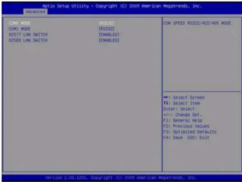
Figure C.1 BIOS COM port setting
C.1.1 Flow Control, Introduction
Consider the situation where someone is helping you harvest papayas from a tree. Your helper climbs up the tree and throws the papayas down to you. You have to put them in buckets. In the normal situation, you can easily catch the papayas, but when one bucket is full and it has to be replaced by an empty one, this action takes more time than is available between two papayas thrown by your helper.
Two different things can occur. Your helper stops until the new bucket is in position, or some papayas are damaged because they fall on the (rock hard, as it happens) ground in the small period you are not able to catch them.
You would probably prefer the first method where your helper stops for a short time. To achieve this, there will be some communication, eye-contact, a yell, or something like that to stop him/her from throwing new papayas. How simple, but is it always this simple? Consider the situation where one computer device sends information to another using a serial connection. Now and then, the receiver needs to do some other actions, to write the contents of its buffers to disk for example. In this period of time no new information can be received. Some communication back to the sender is needed to stop the flow of bytes on the line. A method must be present to tell the sender to pause. To do this, both software and hardware protocols have been defined.
C.1.2 Software Flow Control
Both software and hardware flow control need software to perform the handshaking task. This makes the term software flow control somewhat misleading. What is meant is that with hardware flow control, additional lines are present in the communication cable which signal handshaking conditions. With software flow control, which is also known as XON-XOFF flow control, bytes are sent to the sender using the standard communication lines.
Using hardware flow control requires that more lines be present between the sender and the receiver, leading to a thicker and more expensive cable. Therefore, software flow control is a good alternative if it is not needed to gain maximum performance in communications. Software flow control makes use of the data channel between the two devices, which reduces the bandwidth a bit. The reduction of bandwidth is in most cases however not so astonishing that it is a reason to not use it.
Two bytes have been predefined in the ASCII character set to be used with software flow control. These bytes are named XOFF and XON, because they can stop and restart transmitting. The byte value of XOFF is 19, it can be simulated by pressing Ctrl-S on the keyboard. XON has the value 17 assigned which is equivalent to Ctrl-Q.
Using software flow control is easy. If sending of characters must be postponed, the character XOFF is sent on the line, to restart the communication again XON is used. Sending the XOFF character only stops the communication in the direction of the device which issued the XOFF.
This method has a few disadvantages. One was already mentioned: using bytes on the communication channel takes up some bandwidth. One other reason is more severe. Handshaking is mostly used to prevent an overrun of the receiver buffer, the buffer in memory used to store the recently received bytes. If an overrun occurs, this affects the way new incoming characters on the communication channel are handled. In the worst case where software has been designed badly, these characters are thrown away without checking them. If such a character is XOFF or XON, the flow of communication can be severely damaged. The sender will continuously supply new information if the XOFF is lost, or never send new information if no XON was received.
This also holds for communication lines where signal quality is bad. What happens if the XOFF or XON message is not received clearly because of noise on the line? Special precaution is also necessary that the information sent does not contain the XON or XOFF characters as information bytes.
Therefore, serial communication using software flow control is only acceptable when communication speeds are not too high, and the probability that buffer overruns or data damage occur are minimal.
C.1.3 Hardware Flow Control
Hardware flow control is superior compared to software flow control using the XON and XOFF characters. The main problem is that an extra hardware investment is needed. Extra lines are necessary in the communication cable to carry the handshaking information.
Hardware flow control is sometimes referred to as RTS / CTS flow control. This term mentions the extra input and outputs used on the serial device to perform this type of handshaking. RTS / CTS in its original outlook is used for handshaking between a computer and a device connected to it such as a modem.
First, the computer sets its RTS line to signal the device that some information is present. The device checks if there is room to receive the information and if so, it sets the CTS line to start the transfer. When using a null modem connection, this is somewhat different. There are two ways to handle this type of handshaking in that situation.
One is, where the RTS of each side is connected with the CTS side of the other. In that way, the communication protocol differs somewhat from the original one. The RTS output of computer A signals computer B that A is capable of receiving information, rather than a request for sending information as in the original configuration. This type of communication can be performed with a null modem cable for full handshaking. Although using this cable is not completely compatible with the original way hardware flow control was designed, if software is properly designed for it, it can achieve the highest possible speed because no overhead is present for requesting on the RTS line and answering on the CTS line.
In the second situation of null modem communication with hardware flow control, the software side looks quite similar to the original use of the handshaking lines. The CTS and RTS lines of one device are connected directly to each other. This means, that the request to send query answers itself. As soon as the RTS output is set, the CTS input will detect a high logical value indicating that sending of information is allowed. This implies, that information will always be sent as soon as sending is requested by a device if no further checking is present. To prevent this from happening, two other pins on the connector are used, the data set ready DSR and the data terminal ready DTR. These two lines indicate if the device attached is working properly and willing to accept data. When these lines are cross-connected (as in most null modem cables) flow control can be performed using these lines. A DTR output is set, if that computer accepts incoming characters.
C.1.4 How to Implement
Implementing proper flow control can give some headaches. The main problems are the numerous ways it can be done and especially for null modem connections, the lack of a standard way of doing. The best way to implement rigid flow control in your software is to use preprogrammed routines from a reliable source. The problems involved in the own development of communication routines is often not worth the effort compared to the relative low prices of professional communication libraries. A good library is the COMM-DRV/Lib from Willies Computer Software Co. This library supports all versions of Windows and MS-DOS. XModem, YModem and ZModem file transfer routines are provided and all source code is included. Includes also Modem handling and string handling routines.
C.2 WOL Setting
C.2.1 Introduction
Wake on LAN (WOL, sometimes WoL) is an Ethernet computer networking standard that allows a computer to be turned on or woken up remotely by a network message.
C.2.2 System Requirements - PC Compatible
Wake on LAN (WoL) support is implemented on the motherboard of a computer. Most modern motherboards with an embedded Ethernet controller support WoL without the need for an external cable. Older motherboards must have a WAKEUP-LINK header onboard and connected to the network card via a special 3-pin cable; however, systems supporting the PCI 2.2 standard coupled with a PCI 2.2 compliant network adapter typically do not require a WoL cable as the required standby power is relayed through the PCI bus.
PCI version 2.2 has PME (Power Management Events). What this means is that PCI cards can send and receive PME via the PCI socket directly, without the need for a WOL cable.
Laptops powered by the Intel 3945 chipset or newer (with explicit BIOS support) allow waking up the machine using wireless (802.11 protocol). This is called Wake on Wireless LAN (WoWLAN).
Wake on LAN must be enabled in the Power Management section of the motherboard's BIOS. It may also be necessary to configure the computer to reserve power for the network card when the system is shutdown.
In addition, in order to get WoL to work it is sometimes required to enable this feature on the card. This can be done in Microsoft Windows from the properties of the network card in the device manager, on the "Power Management" tab. Check "Allow this device to bring the computer out of standby" and then "Only allow management stations to bring the computer out of standby" to make sure it does not wake up on all network activity.
C.2.3 How WoL Works
Wake-on-LAN is not restricted to LAN (Local area network) traffic.
The general process of waking a computer up remotely over a network connection can be explained thusly:
The target computer is shut down (Sleeping, Hibernating or Soft Off, i.e. ACPI state G1 or G2), with power reserved for the network card. The network card listens for a specific packet, called the "Magic Packet." The Magic Packet is broadcast on the broadcast address for that particular subnet (or an entire LAN, though this requires special hardware and/or configuration). When the listening computer receives this packet, the network card checks the packet for the correct information. If the Magic Packet is valid, the network card turns on the computer to full power and boots the operating system.
The magic packet is sent on the data link or OSI-2 layer and broadcast to all NICs (within the network of the broadcast address). Therefore, it does not matter whether the remote host has a fixed or dynamic IP-address (OSI-3 layer).
In order for Wake on LAN to work, parts of the network interface need to stay on. This increases the standby power used by the computer. If Wake on LAN is not needed, turning it off may reduce power consumption while the computer is off but still plugged in.
C.2.4 Magic Packet
The Magic Packet is a broadcast frame containing anywhere within its payload 6 bytes of ones (resulting in hexadecimal FF FF FF FF FF) followed by sixteen repetitions of the target computer's MAC address.
Since the Magic Packet is only scanned for the string above, and not actually parsed by a full protocol stack, it may be sent as a broadcast packet of any network- and transport-layer protocol. It is typically sent as a UDP datagram to port 0, 7 or 9, or, in former times, as an IPX packet.
ADVANTECH
Enabling an Intelligent Planet
www.advantech.com
Please verify specifications before quoting. This guide is intended for reference purposes only.
All product specifications are subject to change without notice.
No part of this publication may be reproduced in any form or by any means, electronic, photocopying, recording or otherwise, without prior written permission of the publisher.
All brand and product names are trademarks or registered trademarks of their respective companies.
© Advantech Co., Ltd. 2012
- ARK-3440
- Fanless Embedded Box PC
- Copyright
- Acknowledgements
- Product Warranty (2 years)
- Declaration of Conformity
- FCC Class A
- Technical Support and Assistance
- Warnings, Cautions and Notes
- Safety Instructions
- Ordering information
- Optional accessories
- Contents
- Chapter 1 General Introduction ......1
- Chapter 2 Hardware installation ....7
- Chapter 3 BIOS settings 23
- Appendix A Function Settings...... 41
- Appendix B Display Application 45
- Appendix C Application Notes 49
- Chapter 1
- General Introduction
- Introduction
- Product Features
- General
- Display
- Power Consumption
- Hardware Specifications
- Mechanical Specifications
- Dimensions
- Weight
- Power Requirements
- System power
- RTC battery
- Environmental Specifications
- Operating temperature
- Relative Humidity
- Storage temperature
- Vibration loading during operation
- Shock during operation
- Safety Certifications
- EMC
- Chapter 2
- I/O Locations
- Front Panel Controls, Indicators, & Connectors
- Power ON/OFF Button
- Reset Button
- LED Indicators
- Audio Connectors
- COM Connector
- eSATA Connector
- USB Connector
- Compact Flash Card
- Rear Panel I/O Connectors
- Power Input Connector
- Digital Visual Interface Connector (DVI-I)
- HDMI Connector
- Ethernet Connector (LAN)
- LVDS Connector (Optional)
- LCD Backlight On/Off control Connector (Optional)
- LPT Connector (Optional)
- DIO Connector (Optional)
- Memory Installation
- Compact Flash Installation
- HDD Installation
- Internal fixed HDD installation
- Removable 2.5" Storage Device Installation
- PCI card installation
- Mini PCIe Installation
- Antenna Installation
- Optional Cable Installation
- CPU Thermal Grease Pad
- Part Number Description
- Chapter 3
- BIOS settings
- BIOS Introduction
- Entering BIOS Setup
- Main Setup
- ■ System Date / System Time
- Advanced BIOS Features Setup
- - PCI Common Settings
- ACPI Settings
- Chipset BIOS Feature Setup
- Boot BIOS Feature Setup
- Security BIOS Feature Setup
- Save & Exit BIOS Feature Setup
- Appendix A
- A.1 Function Setting
- Appendix B
- B.1 Introduction
- B.2 LVDS
- B.3 Dual Display
- B.3.1 Display modes
- Clone mode
- Span mode
- ■ Extended mode
- B.4 Display Resolution Setting
- Appendix C
- C.1 RS-485 Supports Auto Flow Control
- C.1.1 Flow Control, Introduction
- C.1.2 Software Flow Control
- C.1.3 Hardware Flow Control
- C.1.4 How to Implement
- C.2 WOL Setting
- C.2.1 Introduction
- C.2.2 System Requirements - PC Compatible
- C.2.3 How WoL Works
- C.2.4 Magic Packet
- ADVANTECH
- www.advantech.com
Brand : Advantech
Model : ARK-3440
Category : Desktop computer