
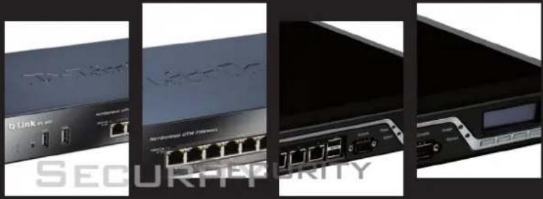
DFL-860E - Pare-feu matériel D-LINK - Free user manual and instructions
Find the device manual for free DFL-860E D-LINK in PDF.


| Product Type | Hardware Firewall / UTM Appliance |
| Model | D-Link DFL-860E |
| Interfaces | 8 x 10/100/1000 Gigabit Ethernet, 2 x SFP |
| Firewall Throughput | 1 Gbps |
| VPN Throughput | 500 Mbps |
| IPS Throughput | 300 Mbps |
| Concurrent Connections | 800,000 |
| New Connections per Second | 30,000 |
| Memory | 4 GB DDR3 RAM |
| Storage | 4 GB Flash Disk |
| Dimensions (W x D x H) | 440 x 250 x 44 mm (1U Rackmount) |
| Weight | 3.5 kg |
| Power Supply | AC 100-240V, 50-60 Hz, 60W |
| Operating Temperature | 0°C to 40°C |
| Storage Temperature | -20°C to 70°C |
| Humidity | 10% to 90% non-condensing |
| Security Functions | Stateful firewall, VPN (IPsec/SSL), IDS/IPS, antivirus, web filtering, application control |
| Management | Web GUI (HTTPS), CLI (SSH), SNMP v1/v2c/v3 |
| Logging and Monitoring | Syslog, SNMP traps, email alerts |
| High Availability | Active/Passive clustering |
| Warranty | 1 year limited hardware warranty |
Frequently Asked Questions - DFL-860E D-LINK
User questions about DFL-860E D-LINK
0 question about this device. Answer the ones you know or ask your own.
Ask a new question about this device
Download the instructions for your Pare-feu matériel in PDF format for free! Find your manual DFL-860E - D-LINK and take your electronic device back in hand. On this page are published all the documents necessary for the use of your device. DFL-860E by D-LINK.
USER MANUAL DFL-860E D-LINK
Building Networks for People
NETWORK SECURITY FIREWALL
USER MANUAL
NETDEFENDOS
VER. 12.00.13
NETWORK SECURITY SOLUTION http://www.dlink.com
User Manual
DFL-260E/860E/870/1660/2560/2560G
NetDefendOS Version 12.00.13
D-Link Corporation
No. 289, Sinhu 3rd Rd, Neihu District, Taipei City 114, Taiwan R.O.C.
http://www.DLink.com
Published 2018-11-07
Copyright © 2018
User Manual
DFL-260E/860E/870/1660/2560/2560G
NetDefendOS Version 12.00.13
Published 2018-11-07
Copyright © 2018
Copyright Notice
This publication, including all photographs, illustrations and software, is protected under international copyright laws, with all rights reserved. Neither this manual, nor any of the material contained herein, may be reproduced without the written consent of D-Link.
Disclaimer
The information in this document is subject to change without notice. D-Link makes no representations or warranties with respect to the contents hereof and specifically disclaims any implied warranties of merchantability or fitness for a particular purpose. D-Link reserves the right to revise this publication and to make changes from time to time in the content hereof without any obligation to notify any person or parties of such revision or changes.
Limitations of Liability
UNDER NO CIRCUMSTANCES SHALL D-LINK OR ITS SUPPLIERS BE LIABLE FOR DAMAGES OF ANY CHARACTER (E.G. DAMAGES FOR LOSS OF PROFIT, SOFTWARE RESTORATION, WORK STOPPAGE, LOSS OF SAVED DATA OR ANY OTHER COMMERCIAL DAMAGES OR LOSSES) RESULTING FROM THE APPLICATION OR IMPROPER USE OF THE D-LINK PRODUCT OR FAILURE OF THE PRODUCT, EVEN IF D-LINK IS INFORMED OF THE POSSIBILITY OF SUCH DAMAGES. FURTHERMORE, D-LINK WILL NOT BE LIABLE FOR THIRD-PARTY CLAIMS AGAINST CUSTOMER FOR LOSSES OR DAMAGES. D-LINK WILL IN NO EVENT BE LIABLE FOR ANY DAMAGES IN EXCESS OF THE AMOUNT D-LINK RECEIVED FROM THE END-USER FOR THE PRODUCT.
Table of Contents
Preface 17
1. NetDefendOS Overview ...... 20
1.1. Features ...... 20
1.2. NetDefendOS Architecture ...... 25
1.2.1. State-based Architecture ...... 25
1.2.2. NetDefendOS Building Blocks 25
1.2.3. Basic Packet Flow 26
1.3. NetDefendOS State Engine Packet Flow 29
2. Management and Maintenance ....34
2.1.Managing NetDefendOS 34
2.1.1. Overview 34
2.1.2. Configuring Management Access 35
2.1.3. Administrator Accounts ...... 41
2.1.4. The Web Interface 42
2.1.5. CLI Access 48
2.1.6. Using the CLI 51
2.1.7. CLI Scripts 59
2.1.8. Secure Copy 65
2.1.9. The Console Boot Menu 67
2.1.10. RADIUS Management Authentication 69
2.1.11. Strong Passwords 72
2.1.12. Management Advanced Settings 73
2.1.13. Working with Configurations 74
2.2. System Date and Time 81
2.2.1. Overview 81
2.2.2. Setting Date and Time Manually 81
2.2.3. Using External Time Servers 83
2.2.4. Settings Summary for Date and Time 86
2.3. Events and Logging 88
2.3.1. Overview 88
2.3.2.Log Messages 88
2.3.3. Log Receiver Types 89
2.3.4. The Memory Log Receiver (Memlog) 90
2.3.5. The Syslog Log Receiver 90
2.3.6.Mail Alerting 93
2.3.7. Severity Filter and Message Exceptions 97
2.3.8. SNMP Traps 98
2.3.9. Advanced Log Settings 100
2.3.10.Logsnoop 100
2.4. Monitoring 104
2.4.1. Real-time Monitor Alerts 104
2.4.2. The Link Monitor 104
2.4.3. Hardware Monitoring 108
2.4.4. Memory Monitoring Settings 110
2.5. SNMP 112
2.5.1. Management with SNMP 112
2.5.2. Persistent SNMP Interface Indexes 116
2.5.3. SNMP Advanced Settings 117
2.6. Diagnostic Tools 119
2.6.1. Overview 119
2.6.2. The ping Command 119
2.6.3. The stats Command 123
2.6.4. The connections Command 124
2.6.5. The dconsole Command 126
2.6.6. The pcapdump Command 127
2.6.7. The traceroute Command 130
2.6.8. The frags Command 132
2.6.9. The selftest Command 134
2.6.10. The techsupport Command 136
2.7. Maintenance 137
2.7.1.Version Update Alerts 137
2.7.2. Auto-Update Mechanism 138
2.7.3. Backing Up Configurations 138
2.7.4. Restore to Factory Defaults 141
2.8. Languages 143
2.9. Diagnostics and Improvements 144
3. Fundamentals ...... 147
3.1. The Address Book 147
3.1.1. Overview 147
3.1.2.IP Address Objects 148
3.1.3. Ethernet Address Objects 150
3.1.4.Address Groups 151
3.1.5. Auto-Generated Address Objects 153
3.1.6. Address Folders 153
3.1.7.FQDN Address Objects 154
3.1.8.FQDN Groups 160
3.2. IPv6 Support 162
3.3. Services 171
3.3.1. Overview 171
3.3.2. Creating Custom Services 173
3.3.3.ICMP Services 177
3.3.4.Custom IP Protocol Services 178
3.3.5. Service Groups 179
3.3.6. Custom Service Timeouts 180
3.3.7. Path MTU Discovery 180
3.4. Interfaces 184
3.4.1. Overview 184
3.4.2. Ethernet Interfaces 186
3.4.3.Link Aggregation 197
3.4.4.VLAN 202
3.4.5. Service VLAN 205
3.4.6.PPPoE 208
3.4.7. GRE Tunnels 211
3.4.8.6in4 Tunnels 215
3.4.9. Loopback Interfaces 219
3.4.10. Interface Groups 224
3.4.11. Layer 2 Pass Through 225
3.5. ARP 227
3.5.1. Overview 227
3.5.2. The ARP Cache 227
3.5.3. ARP Publish 229
3.5.4. The Neighbor Cache 232
3.5.5. ARP Advanced Settings 234
3.6. IP Rule Sets 236
3.6.1. Rulesets Overview 236
3.6.2. Creating IP Policies 238
3.6.3. Using Geolocation 243
3.6.4.IP Rule Set Processing 245
3.6.5. Multiple IP Rule Sets 248
3.6.6.IP Rule Set Folders 253
3.6.7. Configuration Object Groups 254
3.6.8. Stateless Policy 257
3.6.9. Creating IP Rules 259
3.7. Application Control 263
3.8. Schedules 276
3.9. Certificates 281
3.9.1. Overview 281
3.9.2. Uploading and Using Certificates 286
3.9.3.CRL Distribution Point Lists 288
3.9.4. CA Server Access 290
3.9.5. Creating Windows CA Server Requests 292
3.10.DNS 294
- Routing 299
4.1. Overview 299
4.2. Static Routing 300
4.2.1. Static Routing in NetDefendOS 300
4.2.2.Configuring Static Routes 304
4.2.3. Route Failover 310
4.2.4. Host Monitoring for Route Failover 313
4.2.5. Advanced Routing Settings for Route Failover 316
4.2.6.Proxy ARP 317
4.2.7. Broadcast Packet Forwarding 319
4.3. Policy-based Routing 322
4.4. Route Load Balancing 330
4.5. Active-Active Setup 337
4.6. Virtual Routing 340
4.6.1. Overview 340
4.6.2.A Simple Scenario 340
4.6.3. The Disadvantage of Routing Rules 342
4.6.4. IP Rule Sets with Virtual Routing 345
4.6.5. Multiple IP rule sets 346
4.6.6. Trouble Shooting 346
4.7. OSPF 348
4.7.1. Dynamic Routing 348
4.7.2. OSPF Concepts 351
4.7.3. OSPF Components 356
4.7.4. Dynamic Routing Rules 363
4.7.5. Setting Up OSPF 366
4.7.6. An OSPF Example 370
4.7.7. OSPF Troubleshooting 375
4.8. Multicast Routing 378
4.8.1. Overview 378
4.8.2. Multicast Forwarding with Multicast Policies 379
4.8.3. IGMP Configuration 383
4.8.4. Advanced IGMP Settings 388
4.8.5. Tunneling Multicast using GRE 390
4.9. Transparent Mode 394
4.9.1. Overview 394
4.9.2. Enabling Internet Access 399
4.9.3. A Transparent Mode Use Case 401
4.9.4. Spanning Tree BPDU Support 403
4.9.5. MPLS Pass Through 404
4.9.6. Advanced Settings for Transparent Mode 405
- DHCP Services 408
5.1. Overview 408
5.2. IPv4 DHCP Client 410
5.3. IPv4 DHCP Server 412
5.3.1. Static IPv4 DHCP Hosts 416
5.3.2. Custom IPv4 Options 417
5.4. IPv4 DHCP Relay 419
5.5. IP Pools 425
5.6.DHCPv6 428
5.6.1. DHCPv6 Client 428
5.6.2. DHCPv6 Server 431
- Application Layer Security 438
6.1. ALGs 438
6.1.1. Overview 438
6.1.2. HTTP ALG 440
6.1.3. FTP ALG 455
6.1.4. TFTP ALG 473
6.1.5. SMTP ALG 476
6.1.6. POP3 ALG 489
6.1.7. IMAP ALG 497
6.1.8. PPTP ALG 502
6.1.9. SIP ALG 505
6.2.6. The WCF Performance Log 588
6.3. Email Control 591
6.3.1. Email Control Profiles with IP Policies 591
6.3.2.DNSBL Processing 596
6.3.3. SMTP Anti-Spam with IP Rules 598
6.4. Anti-Virus Scanning 603
6.4.1. Overview 603
6.4.2.Implementation 604
6.4.3. Activating Anti-Virus Scanning 606
6.4.4. Anti-Virus with ZoneDefense 611
6.4.5. The Anti-Virus Cache 612
6.5. File Control 614
- Threat Prevention 619
7.1. Access Rules 619
7.1.1. Overview 619
7.1.2.IP Spoofing 620
7.1.3. Access Rule Settings 620
7.2. IP Reputation 623
7.3. Botnet Protection 629
7.4.DoS Protection 631
7.4.1. Overview 631
7.4.2. Setting up DoS Protection 631
7.4.3.DoS Attack Examples 632
7.5. Scanner Protection 637
7.6. Intrusion Detection and Prevention 638
7.6.1. Overview 638
7.6.2. IDP Configuration Components 639
7.6.3. IDP Signatures and Signature Groups 641
7.6.4. Insertion/Evasion Attack Prevention 644
7.6.5. Setting Up IDP 645
7.6.6. SMTP Log Receiver for IDP Events 648
7.6.7. Best Practice Deployment 649
7.7. Threshold Rules 651
7.8. Blacklisting Hosts and Networks 655
7.9. ZoneDefense 659
- Address Translation 666
8.1. Overview 666
8.2. NAT 668
8.3. NAT Pools 675
8.4.SAT 679
8.4.1. Introduction 679
8.4.2. One-to-One IP Translation 681
8.4.3. Many-to-Many IP Translation 684
8.4.4. Many-to-One IP Translation 687
8.4.5. SAT with Stateless IP Rule Set Entries 689
8.4.6. Combining SAT with NAT 691
8.4.7. Port Translation 694
8.4.8. Protocols Handled by SAT 697
8.4.9.SAT Setup Using IP Rules 698
8.5. Automatic Translation 705
8.5.1. NAT Only Translation 706
8.5.2. NAT/SAT Translation 707
9.User Authentication 712
9.1. Overview 712
9.2. Authentication Setup 715
9.2.1. Authentication Setup Summary 715
9.2.2. Local User Databases 715
9.2.3.External RADIUS Servers 719
9.2.4.External LDAP Servers 722
9.2.5. Authentication Rules 729
9.2.6. HTTP Authentication 732
9.2.7.MAC Authentication 736
9.3. Customizing Authentication HTML 738
9.4. IP Policies Requiring Authentication 742
9.5.Brute Force Protection 744
9.6.User Identity Awareness 746
9.6.1. Overview 746
9.6.2. Setting Up Identity Awareness 747
9.6.3. Monitoring Identity Awareness Activity 750
9.7. Multi Factor Authentication 751
9.8. Radius Relay 753
9.9.RADIUS Accounting 760
9.9.1. Overview 760
9.9.2. RADIUS Accounting Messages 760
9.9.3.Interim Accounting Messages 762
9.9.4.Configuring RADIUS Accounting 762
9.9.5. RADIUS Accounting Security 764
9.9.6. RADIUS Accounting and High Availability 764
9.9.7. Handling Unresponsive RADIUS Servers 764
9.9.8. Accounting and System Shutdowns 765
9.9.9. Limitations with NAT 765
9.9.10. Advanced RADIUS Settings 765
- VPN 768
10.1. Overview 768
10.1.1.VPN Usage 768
10.1.2. VPN Encryption 769
10.1.3. VPN Planning 770
10.1.4.Key Distribution 770
10.1.5. The TLS Alternative for VPN 771
10.2. VPN Quick Start 772
10.2.1.IPsec LAN-to-LAN with Pre-shared Keys 773
10.2.2.IPsec LAN-to-LAN with Certificates 775
10.2.3.IPsec Roaming Clients with Pre-shared Keys 776
10.2.4.IPsec Roaming Clients with Certificates 779
10.2.5. L2TP/IPsec Roaming Clients with Pre-Shared Keys 780
10.2.6. L2TP/IPsec Roaming Clients with Certificates 781
10.2.7. PPTP Roaming Clients 782
10.3.IPsec 784
10.3.1.IPsec Principles 784
10.3.2.IPsec Tunnels in NetDefendOS 789
10.3.3. IPsec Tunnel Properties 791
10.3.4.IPsec Proposal Lists 798
10.3.5. Pre-shared Keys 799
10.3.6. LAN-to-LAN Tunnels with Pre-shared Keys 801
10.3.7.IPsec Roaming Clients 805
10.3.8.IPsec with Certificates 809
10.3.9.IPsec Tunnel Selection 815
10.3.10.IPsec IPv6 Support 816
10.3.11.Config Mode 817
10.3.12. IKEv2 Support 820
10.3.13. Setup for IKEv2 Roaming Clients 822
10.3.14. Setup for iOS Roaming Clients 829
10.3.15. Using IPsec Profiles 831
10.3.16.MOBIKE Support 837
10.3.17. IPsec Tunnel Monitoring 837
10.3.18. Using ID Lists with Certificates 839
10.3.19.DiffServ with IPsec 842
10.3.20. NAT Traversal 843
10.3.21. Using Alternate LDAP Servers 844
10.3.22. IPsec Advanced Settings 845
10.3.23.IPsec Troubleshooting 849
10.4.PPTP/L2TP 862
10.4.1.PPTP Servers 862
10.4.2. L2TP Servers 863
10.4.3. L2TP/PPTP Server Advanced Settings 869
10.4.4. PPTP/L2TP Clients 870
10.4.5. The l2tp and pptp Commands 872
10.5. L2TP Version 3 874
10.5.1. L2TPv3 Server 875
10.5.2. L2TPv3 Client 882
10.6. SSL VPN 886
10.6.1. Overview 886
10.6.2. Configuring SSL VPN in NetDefendOS 887
10.6.3. Installing the SSL VPN Client 889
10.6.4. SSL VPN Setup Example 893
- Traffic Management 897
11.1. Traffic Shaping 897
11.1.1. Overview 897
11.1.2. Traffic Shaping in NetDefendOS 898
11.1.3. Simple Bandwidth Limiting 901
11.1.4. Limiting Bandwidth in Both Directions 902
11.1.5. Creating Differentiated Limits Using Chains 904
11.1.6. Precedences 905
11.1.7. Pipe Groups 909
11.1.8. Traffic Shaping with VPN and Tunnels 912
11.1.9. Traffic Shaping Recommendations 913
11.1.10. A Summary of Traffic Shaping 914
11.1.11.More Pipe Examples 914
11.2. IDP Traffic Shaping 919
11.2.1. Overview 919
11.2.2. Setting Up IDP Traffic Shaping 919
11.2.3. Processing Flow 920
11.2.4. The Importance of Specifying a Network 920
11.2.5. A P2P Scenario 921
11.2.6. Viewing Traffic Shaping Objects 922
11.2.7. Guaranteeing Instead of Limiting Bandwidth 923
11.2.8. Logging 923
11.3.Server Load Balancing 924
11.3.1. Overview 924
11.3.2.SLB Distribution Algorithms 926
11.3.3. Selecting Stickiness 926
11.3.4.SLB Algorithms and Stickiness 928
11.3.5.Server Health Monitoring 929
11.3.6. Behavior After Server Failure 930
11.3.7. Setting Up SLB 931
- High Availability 938
12.1. Overview 938
12.2.HA Mechanisms 941
12.3. Setting Up HA 945
12.3.1. Hardware Setup 945
12.3.2. Wizard HA Setup 948
12.3.3.Manual HA Setup 949
12.3.4. Verifying that the Cluster Functions Correctly 950
12.3.5. Unique Shared Mac Addresses 951
12.4.HA Issues 952
12.5. Upgrading an HA Cluster 955
12.6. Link Monitoring and HA 957
12.7.HA Advanced Settings 958
- Advanced Settings 961
13.1. IP Level Settings 961
13.2. TCP Settings 965
13.3.ICMP Settings 971
13.4. State Settings 972
13.5.Connection Timeout Settings 974
13.6. Length Limit Settings 976
13.7. Fragmentation Settings 979
13.8. Local Fragment Reassembly Settings 983
13.9. SSL/TLS Settings 984
13.10. Miscellaneous Settings 987
A. Subscribing to Updates 992
B. IDP Signature Groups 996
C. Verified MIME filetypes 1000
D. The OSI Framework 1004
E. DFL-260E/860E Port Based VLAN 1005
F. Third Party Software Licenses 1007
Alphabetical Index 1013
List of Figures
1.1. Packet Flow Schematic Part I 29
1.2. Packet Flow Schematic Part II 30
1.3. Packet Flow Schematic Part III 31
1.4. Expanded Apply Rules Logic ...... 32
2.1. Management Workstation Connection 43
3.1. Path MTU Discovery Processing 181
3.2. Link Aggregation 198
3.3.VLAN Connections 203
3.4.A Service VLAN Use Case 206
3.5. An Example of GRE Usage 213
3.6.IP6in4 Tunnel Usage 216
3.7. Acting as a 6in4 Tunnel Server 218
3.8. A Use Case for Loopback Interfaces 221
3.9. Setting Up Loopback Interfaces with Routing Tables 222
3.10.Components of Loopback Interface Setup 223
3.11. An ARP Publish Ethernet Frame 231
3.12. Simplified NetDefendOS Traffic Flow 246
3.13. Certificate Validation Components 291
4.1.A Typical Routing Scenario 301
4.2. Using Local IP Address with an Unbound Network 304
4.3. A Route Failover Scenario for ISP Access 311
4.4.A Proxy ARP Example 318
4.5. The RLB Round Robin Algorithm 331
4.6. The RLB Spillover Algorithm 332
4.7.A Route Load Balancing Scenario 334
4.8. Active-Active Setup 337
4.9. Active-Active Load Balancing 338
4.10. Virtual Routing 341
4.11. The Disadvantage of Routing Rules 342
4.12. The Advantage of Virtual Routing 343
4.13. A Simple OSPF Scenario 349
4.14. OSPF Providing Route Redundancy 350
4.15. Virtual Links Connecting Areas 354
4.16. Virtual Links with Partitioned Backbone 355
4.17. NetDefendOS OSPF Objects 356
4.18. OSPF Route Aggregation Example 362
4.19. Dynamic Routing Rule Objects 364
4.20. An OSPF Example 370
4.21. Multicast Snoop Mode 383
4.22. Multicast Proxy Mode 384
4.23. Tunneling Multicast using GRE 391
4.24. Non-transparent Mode Internet Access 399
4.25. Transparent Mode Internet Access 400
4.26. Transparent Mode Use Case 401
4.27. An Example BPDU Relaying Scenario 404
5.1. DHCP Server Objects 416
5.2. DHCP Relay with Proxy ARP 421
6.1. HTTP ALG Processing Order 441
6.2. FTP ALG Hybrid Mode 457
6.3. SMTP ALG Usage 477
6.4. SMTP ALG Processing Order 480
6.5. POP3 ALG Usage 490
6.6. PPTP ALG Usage 502
6.7.TLS Termination 557
6.8. Web Content Filtering Flow 571
6.9. DNSBL Anti-Spam Processing 597
6.10. Anti-Virus Malicious File Message 604
6.11. Anti-Virus Malicious URL Message 605
7.1. IDP Signature Selection 640
8.1. NAT IP Address Translation 669
8.2. The NAT Translation Process 670
8.3. Anonymizing with NAT 674
8.4. SAT Translation with Internal Clients 683
8.5. Combining SAT with NAT in an IP Policy 692
8.6. An Automatic NAT Address Translation Scenario ...... 706
8.7. An Automatic NAT/SAT Address Translation Scenario 708
9.1. Normal LDAP Authentication 728
9.2. LDAP for PPP with CHAP, MS-CHAPv1 or MS-CHAPv2 729
9.3.User Identity Awareness 746
9.4. Multi Factor Authentication 752
10.1. The AH protocol 788
10.2. The ESP protocol 789
10.3. PPTP Client Usage 872
10.4. An L2TPv3 Example 876
10.5. The SSL VPN Client Login 891
10.6. The SSL VPN Client Statistics 892
11.1. Pipe Rules Determine Pipe Usage 900
11.2. A Stateless Policy Bypasses Traffic Shaping 901
11.3. Differentiated Limits Using Chains 904
11.4. The Eight Pipe Precedences 905
11.5. Minimum and Maximum Pipe Precedence 907
11.6. Traffic Grouped By IP Address 911
11.7. A Basic Traffic Shaping Scenario 915
11.8. IDP Traffic Shaping P2P Scenario 922
11.9. A Server Load Balancing Configuration 925
11.10. Connections from Three Clients 928
11.11. Stickiness and Round-Robin 928
11.12. Stickiness and Connection-rate 929
12.1. High Availability Setup 947
D.1. The 7 Layers of the OSI Model .... 1004
List of Examples
- Example Notation ...... 17
2.1. Changing the Management Validation Timeout 38
2.2. Changing the Management Interface IP Address 39
2.3. Changing a Remote Management Object 39
2.4. Changing the HA Management IP Address 40
2.5. Adding Remote Management via HTTPS 41
2.6. Remote Management via HTTPS with CA Signed Certificates 47
2.7. Enabling SSH Remote Access 48
2.8. Enabling SSH Authentication Using SSH Keys 50
2.9. Running a CLI Script from the Web Interface 65
2.10. Enabling RADIUS Management Authentication 71
2.11. Disabling Strong Passwords 73
2.12. Listing Configuration Objects ..... 75
2.13. Displaying a Configuration Object 76
2.14. Editing a Configuration Object 76
2.15. Adding a Configuration Object 77
2.16. Deleting a Configuration Object 78
2.17. Undeleting a Configuration Object 78
2.18. Listing Modified Configuration Objects 79
2.19. Activating and Committing a Configuration 79
2.20. Setting the Current Date and Time 81
2.21. Setting the Time Zone Location 82
2.22. Using the D-Link Time Server 84
2.23.Configuring Custom Time Servers 84
2.24. Manually Triggering a Time Synchronization 85
2.25.Modifying the Maximum Adjustment Value 85
2.26. Forcing Time Synchronization 86
2.27. Enable Logging to a Syslog Host 91
2.28. Enabling Syslog RFC 5424 Compliance with Hostname 92
2.29. Setting up a Mail Alerting Object 96
2.30.Configuring an SNMPv3 Event Receiver 99
2.31.Link Monitor Setup 107
2.32. Enabling SNMP Versions 1 and 2c Monitoring 114
2.33. Enabling SNMP Version 3 Monitoring 115
2.34. Enabling SNMP Index Persistence 117
2.35. Creating techsupport Output 136
2.36. Disabling NetDefendOS Release Notifications 137
2.37. Downloading a Complete System Backup 140
2.38.Complete Hardware Reset to Factory Defaults 141
2.39. Disabling Diagnostics and Quality Improvements Messaging 145
3.1. Adding a Simple IP4 Address 148
3.2. Adding an IPv4 Network 149
3.3. Adding an IPv4 Range 149
3.4. Deleting an Address Object 150
3.5. Adding an Ethernet Address 150
3.6. Creating an IP4 Group Object 152
3.7. Adding an Address Folder Object 154
3.8. Adding an FQDN Address Object 158
3.9. Setting the DNS Minimum TTL and Minimum Lifetime 159
3.10. Using FQDN Objects with an IP Policy 159
3.11. Adding an FQDN Group Object 161
3.12. Enabling IPv6 on an Ethernet Interface 162
3.13.Manually Adding IPv6 Interface Addresses 164
3.14. Enabling IPv6 Advertisements 165
3.15. Adding an IPv6 Route and Enabling Proxy ND 166
3.16. Listing the Available Services 172
3.17. Viewing a Specific Service 173
3.18. Creating a Custom TCP/UDP Service 176
3.19. Adding an IP Protocol Service 178
3.20. Creating a Service 179
3.21. Enabling Path MTU Discovery on an IP Policy 182
3.22. Link Aggregation 201
3.23. Defining a VLAN 205
3.24.Defining a Service VLAN 206
3.25. Configuring a PPPoE Client 210
3.26. 6in4 Tunnel Configuration ...... 217
3.27. Creating a Loopback Interface Pair 223
3.28. Creating an Interface Group 224
3.29. Enabling Layer 2 Pass Through 225
3.30. Displaying the ARP Cache 228
3.31. Flushing the ARP Cache 228
3.32. Defining an ARP/Neighbor Discovery Object 231
3.33. IP Policy Setup to Allow LAN Connections to a DMZ 240
3.34. Creating a Drop-All IP Policy 242
3.35. Setting up a Geolocation Filter 244
3.36. Creating an IP Rule Set 248
3.37. Adding a Goto Rule 252
3.38. Adding a Return Rule 252
3.39. Creating a Stateless Policy 258
3.40. Creating an Allow IP Rule 260
3.41. Disabling IP Rule Object Usage 261
3.42. Specifying an Application Control Policy 263
3.43. Using an Application Control Rule Set 266
3.44. Application Content Control 269
3.45. Application Content Control with Logging 270
3.46. Setting up a Schedule Profile with an IP Policy 277
3.47. Setting up an Advanced Schedule Profile with an IP Policy 279
3.48. Uploading a Certificate with the Web Interface 287
3.49. Associating Certificates with IPsec Tunnels 288
3.50.CRL Distribution Point List 288
3.51.Configuring DNS Servers 294
4.1. Displaying the main Routing Table 307
4.2. Adding a Route to the main Table 308
4.3. Displaying the Core Routes 309
4.4. Enabling Broadcast Forwarding on a Route 321
4.5. Creating a Routing Table 323
4.6. Adding Routes 324
4.7. Creating a Routing Rule 324
4.8. Policy-based Routing with Multiple ISPs 327
4.9. Setting Up RLB 335
4.10. Creating an OSPF Router Process 370
4.11. Add an OSPF Area 371
4.12.Add OSPF Interface Objects 372
4.13. Import Routes from an OSPF AS into the Main Routing Table 372
4.14. Exporting the Routes into an OSPF AS 374
4.15. Enabling OSPF Debug Log Events 376
4.16. Multicast Forwarding With No Address Translation 379
4.17. Multicast Forwarding With Address Translation 381
4.18. IGMP - No Address Translation 384
4.19. if1 Configuration 386
4.20. if2 Configuration - Group Translation 387
4.21. A Transparent Mode Use Case 401
5.1. Enabling an Ethernet Interface as a DHCP Client 410
5.2. Setting up an IPv4 DHCP server 414
5.3. Static IPv4 DHCP Host Assignment 416
5.4. Setting up a DHCP Relayer 422
5.5. Creating an IP Pool 427
5.6.DHCPv6 Client Setup 430
5.7. DHCPv6 Server Setup 433
5.8. Static DHCPv6 Host Assignment 435
6.1. URL Redirection with an IP Policy 445
6.2. Stripping ActiveX and Java applets 449
6.3. URL Filtering Setup Using an IP Rule 450
6.4. Using the Light Weight HTTP ALG 453
6.5. FTP ALG Setup Using IP Policies to Protect an FTP Server 461
6.6. FTP ALG Setup Using an IP Policy to Protect FTP Clients 464
6.7. FTP ALG Setup Using IP Rules to Protect an FTP Server 468
6.8. FTP ALG Setup Using IP Rules to Protect FTP Clients 471
6.9. TFTP ALG Setup Using an IP Policy 475
6.10. SMTP ALG Setup Using an IP Policy 481
6.11. SMTP ALG Setup with IP Rules 486
6.12. POP3 ALG Setup Using an IP Policy 492
6.13. POP3 ALG Setup Using IP Rules 495
6.14. IMAP ALG Setup 498
6.15. PPTP ALG Setup Using an IP Policy 503
6.16. SIP with Local Clients/Internet Proxy Using IP Policies 512
6.17. SIP with Local Clients/Internet Proxy Using IP Rules 519
6.18. Protecting Internal H.323 Phones Using IP Policies 524
6.19. H.323 with a Private Address Using IP Policies 527
6.20. Two Phones Behind Different Clavister Firewalls Using IP Policies 529
6.21. Using Private IPv4 Addresses with IP Policies 531
6.22. H.323 with Gatekeeper Using IP Policies 533
6.23. H.323 with Gatekeeper and two D-Link firewalls 536
6.24. Using H.323 in an Enterprise Environment 538
6.25. Configuring remote offices for H.323 542
6.26. Allowing the H.323 Gateway to register with the Gatekeeper 542
6.27. Protecting Internal H.323 Phones Using IP Rules 543
6.28. H.323 with a Private Address Using IP Rules 545
6.29. Two Phones Behind Different Firewalls Using IP Rules 547
6.30. Using Private IPv4 Addresses - IP Rules Version 548
6.31.H.323 with Gatekeeper Using IP Rules 550
6.32. H.323 with Gatekeeper and two D-Link firewalls Using IP Rules 552
6.33. Using H.323 in an Enterprise Environment 553
6.34. Configuring remote offices for H.323 Using IP Rules 555
6.35. Allowing the H.323 Gateway to register with the Gatekeeper Using IP Rules ..... 556
6.36. TLS ALG Setup Using an IP Policy 559
6.37. Using the DNS ALG with a Protected DNS Server 566
6.38. Using the DNS ALG with Protected Clients 567
6.39. WCF Setup Using an IP Policy 573
6.40. WCF Setup Using IP Rules 574
6.41. Enabling Audit Mode 576
6.42. Reclassifying URLs Blocked by WCF 577
6.43. Editing Content Filtering HTTP Banner Files 587
6.44. Enabling the WCF Performance Log 590
6.45. Anti-Virus Setup Using an IP Policy 608
6.46. Anti-Virus Setup Using an IP Rule 610
6.47. Changing the Anti-Virus Cache Lifetime 612
6.48. File Control Setup with an IP Policy 615
7.1. Setting up an Access Rule 621
7.2. Enabling IP Reputation Logging 627
7.3. Enabling Botnets Protection 630
7.4. Enabling DoS Protection 632
7.5. Enabling Scanner Protection 637
7.6. Setting up IDP for a Mail Server 646
7.7.Configuring an SMTP Log Receiver 648
7.8. Creating a Threshold Rule 653
7.9. Blacklisting an IP Network 657
7.10. Adding a Host to the Whitelist 658
7.11. Setting Up ZoneDefense 662
8.1. Setting Up NAT with an IP Policy 671
8.2. Setting Up NAT with an IP Rule 672
8.3. Using NAT Pools 677
8.4. One-to-One IP Translation Using an IP Policy 681
8.5. Many-to-Many SAT Translation Using an IP Policy 685
8.6. Many-to-One SAT Translation Using an IP Policy 687
8.7. Stateless One-to-One SAT Translation Using Stateless Policies 689
8.8. Combining SAT with NAT in an IP Policy 693
8.9. Port Translation Using an IP Policy 696
8.10. One-to-One IP Translation Using IP Rules 699
8.11. Many-to-Many SAT Translation Using IP Rules 700
8.12. All-to-One SAT Translation Using IP Rules 702
8.13. Automatic NAT Translation with an IP Policy 707
8.14. Automatic SAT/NAT Translation with an IP Policy 708
9.1.Creating a Local User Database 716
9.2. Adding a User with Group Membership 716
9.3.Configuring a RADIUS Server 721
9.4.User Authentication Setup for Web Access 734
9.5. Editing Content Filtering HTTP Banner Files 739
9.6. Creating an IP Policy Requiring Authentication 742
9.7. Enabling User Identity Awareness 748
9.8.Configuring Radius Relay 756
9.9. RADIUS Accounting Server Setup 763
10.1. Creating and Using an IPsec Proposal List 798
10.2. Creating and Using a PSK 800
10.3. PSK Based LAN-to-LAN IPsec Tunnel Setup 801
10.4. PSK Based IPsec Tunnel for Roaming Clients Setup 806
10.5. Certificate Based LAN-to-LAN IPsec Tunnel Setup 810
10.6. Certificate Based IPsec Tunnels for Roaming Clients 813
10.7. Creating an IKE Config Mode Pool 818
10.8. Enabling Config Mode on an IPsec Tunnel 819
10.9. IKEv2 EAP Client Setup using RADIUS 824
10.10. IKEv2 EAP Client Setup using a Local Database 827
10.11.IPsec Setup with a LAN to LAN VPN Object 832
10.12.IPsec Setup with a Roaming VPN Object 834
10.13.IPsec Setup with a Azure VPN Object 836
10.14. Enabling IPsec Tunnel Monitoring 839
10.15. Using an ID List 841
10.16. Setting up an LDAP server 845
10.17. Setting up a PPTP server 863
10.18. Setting up an L2TP server 864
10.19. Setting up an L2TP Tunnel Over IPsec 865
10.20. L2TPv3 Server Setup 876
10.21. L2TPv3 Server Setup With IPsec 878
10.22. L2TPv3 Server Setup For VLANs 879
10.23. L2TPv3 Client Setup 882
10.24. L2TPv3 Client Setup With IPsec 883
10.25. Setting Up an SSL VPN Interface 893
10.26. Setting SSL VPN Interface Client Routes 895
11.1. Applying a Simple Bandwidth Limit 901
11.2. Limiting Bandwidth in Both Directions 903
11.3. Setting up SLB with an SLB Policy 931
11.4. Setting up SLB with IP Rules 933
12.1. Enabling Automatic Cluster Synchronization 939
Preface
Intended Audience
The target audience for this reference guide is Administrators who are responsible for configuring and managing D-Link firewalls which are running the NetDefendOS operating system. This guide assumes that the reader has some basic knowledge of networks and network security.
Text Structure and Conventions
The text is broken down into chapters and sub-sections. Numbered sub-sections are shown in the table of contents at the beginning. An index is included at the end of the document to aid with alphabetical lookup of subjects.
Where a "See chapter/section" link (such as: see Chapter 10, VPN) is provided in the main text, this can be clicked to take the reader directly to that reference.
Text that may appear in the user interface of the product is designated by being in bold case. Where a term is being introduced for the first time or being stressed it may appear in italics.
Where console interaction is shown in the main text outside of an example, it will appear in a box with a gray background.
Where a web address reference is shown in the text, clicking it will open the specified URL in a browser in a new window (some systems may not allow this). For example, http://www.dlink.com.
Screenshots
This guide contains a minimum of screenshots. This is deliberate and is done because the manual deals specifically with NetDefendOS and administrators have a choice of management user interfaces. It was decided that the manual would be less cluttered and easier to read if it concentrated on describing how NetDefendOS functions rather than including large numbers of screenshots showing how the various interfaces are used. Examples are given but these are largely textual descriptions of management interface usage.
Examples
Examples in the text are denoted by the header Example and appear with a gray background as shown below. They contain a CLI example and/or a Web Interface example as appropriate. (The NetDefendOS CLI Reference Guide documents all CLI commands.)
Example 1. Example Notation
Information about what the example is trying to achieve is found here, sometimes with an explanatory image.
Command-Line Interface
The Command Line Interface example would appear here. It would start with the command prompt followed by the command:
gw-world:/> somecommand someparameter=somevalue
Web Interface
The Web Interface actions for the example are shown here. They are also typically a numbered list showing what items need to be opened followed by information about the data items that need to be entered:
-
Go to: Item X > Item Y > Item Z
-
Now enter:
- Dataltem1: datavalue1
- Dataltem2: datavalue2
Highlighted Content
Sections of text which the reader should pay special attention to are indicated by icons on the left hand side of the page followed by a short paragraph in italicized text. Such sections are of the following types with the following purposes:

Note
This indicates some piece of information that is an addition to the preceding text. It may concern something that is being emphasized, or something that is not obvious or explicitly stated in the preceding text.

Tip
This indicates a piece of non-critical information that is useful to know in certain situations but is not essential reading.

Caution
This indicates where the reader should be careful with their actions as an undesirable situation may result if care is not exercised.

Important
This is an essential point that the reader should read and understand.

Warning
This is essential reading for the user as they should be aware that a serious situation may result if certain actions are taken or not taken.
Trademarks
Certain names in this publication are the trademarks of their respective owners.
Windows, Windows Server, Hyper-V are either registered trademarks or trademarks of Microsoft Corporation in the United States and/or other countries.
Apple, Mac and MacOS are trademarks of Apple Inc. registered in the United States and/or other countries.
Chapter 1: NetDefendOS Overview
This chapter outlines the key features of NetDefendOS.
- Features, page 20
• NetDefendOS Architecture, page 25 - NetDefendOS State Engine Packet Flow, page 29
1.1. Features
D-Link NetDefendOS is the base software system that runs on D-Link hardware products.
NetDefendOS as a Network Security Operating System
Designed as a network security operating system, NetDefendOS features high throughput performance with high reliability plus super-granular control. In contrast to products built on top of standard operating systems such as Unix or Microsoft Windows, NetDefendOS offers seamless integration of all its subsystems, in-depth administrative control of all functionality, as well as a minimal attack surface which helps to negate the risk from security attacks.
NetDefendOS Objects
From the administrator's perspective the conceptual approach of NetDefendOS is to visualize operations through a set of logical building blocks or objects. These objects allow the configuration of NetDefendOS in an almost limitless number of different ways. This granular control allows the administrator to meet the requirements of the most demanding network security scenarios.
Key Features
NetDefendOS has an extensive feature set. The list below presents the key features of the product:
IP Routing NetDefendOS provides a variety of options for IP routing
including static routing, dynamic routing (with OSPF), virtual routing as well as multicast routing capabilities. In addition, NetDefendOS supports features such as Virtual
| LANs, Route Monitoring, Proxy ARP and Transparency. | ||
| For more information about this, see Chapter 4, Routing. | ||
| Firewalling Policies | NetDefendOS provides stateful inspection-based firewalling for a wide range of protocols such as TCP, UDP and ICMP. The administrator can define detailed firewalling policies based on source/destination network/interface, protocol, ports, user credentials, time-of-day and more.Section 3.6, "IP Rule Sets" describes how to set up these policies to determine what traffic is allowed or rejected by NetDefendOS. | |
| Address Translation | For functionality as well as security reasons, NetDefendOS supports policy-based address translation. Dynamic Address Translation (NAT) as well as Static Address Translation (SAT) is supported, and resolves most types of address translation needs.This feature is covered in Chapter 8, Address Translation. | |
| VPN | NetDefendOS supports a range of Virtual Private Network (VPN) solutions. Support exists for IPsec, L2TP, L2TPv3, PPTP, as well as SSL VPN, with security policies definable for individual VPN connections.This topic is covered in Chapter 10, VPN. | |
| TLS Termination | NetDefendOS supports TLS termination so that the D-Link firewall can act as the endpoint for connections by HTTP web-browser clients (this feature is sometimes called SSL termination).For detailed information, see Section 6.1.11, "TLS ALG". | |
| Application Control | NetDefendOS is able to identify data connections relating to particular applications and perform defined actions for those data streams such as blocking or traffic shaping. An example of an application is BitTorrent peer to peer streaming but could also relate to accessing certain websites such as Facebook.For detailed information, see Section 3.7, "Application Control". | |
| Anti-Virus Scanning | NetDefendOS features integrated anti-virus functionality. Traffic passing through the firewall can be subjected to in-depth scanning for viruses, and virus sending hosts can be black-listed and blocked.For details of this feature, seeSection 6.4, "Anti-Virus Scanning". | |
| Intrusion Detection and Prevention | To mitigate application-layer attacks towards vulnerabilities in services and applications, NetDefendOS provides a powerful Intrusion Detection and Prevention (IDP) engine. The IDP engine is policy-based and is able to perform high-performance scanning and detection of attacks and can perform blocking and optional black-listing of attacking hosts. | |
| More information about IDP can be found in Section 7.6, "Intrusion Detection and Prevention". | ||
| Web Content Filtering | NetDefendOS provides various mechanisms for filtering web content that is deemed inappropriate according to a web usage policy. With Web Content Filtering (WCF) web content can be blocked based on the URL. In addition, websites can be whitelisted or blacklisted.More information about this topic can be found in Section 6.2, "Web Content Filtering". | |
| Traffic Management NetDefendOS | provides broad traffic management capabilities through Traffic Shaping, Threshold Rules and Server Load Balancing.Traffic Shaping enables limiting and balancing of bandwidth; Threshold Rules allow specification of thresholds for sending alarms and/or limiting network traffic; Server Load Balancing enables a device running NetDefendOS to distribute network load to multiple hosts.These features are discussed in detail in Chapter 11, Traffic Management. | |
 | NoteThe threshold rules feature is not available on the DFL-260E. | |
| User Authentication | A NetDefendOS device can be used for authenticating users before allowing access to protected resources. Multiple local user databases are supported as well as multiple external RADIUS servers, and separate authentication policies can be defined to support separate authentication schemes for different kinds of traffic.In addition, NetDefendOS supports User Identity Awareness. This means Windows based clients need only be authenticated once by a Windows Active DirectoryTM server and the authenticated state is then relayed to NetDefendOS.See Chapter 9, User Authentication for detailed information. | |
| Operations and Maintenance | Administrator management of NetDefendOS is possible through either a Web-based User Interface (the WebUI) or via a Command Line Interface (the CLI). NetDefendOS also provides detailed event and logging capabilities plus support for monitoring through SNMP.More detailed information about this topic can be found in Chapter 2, Management and Maintenance. | |
| High Availability | High Availability (HA) is supported through automatic fault-tolerant failover to a secondary D-Link firewall. The two devices act together as a cluster, with one being active while the other is passive but constantly mirroring the state of the active unit. | |
This feature is described in more detail in Chapter 12, High Availability.

Note
The HA feature is not available with the DFL-260E and DFL-860E.
ZoneDefense NetDefendOS can be used to control external switches
using the ZoneDefense feature. This allows NetDefendOS to isolate portions of a network that contain hosts that are the source of undesirable network traffic. This is discussed further in Section 7.9, "ZoneDefense".

Note
NetDefendOS ZoneDefense is not available on the DFL-260E.
Virtual Routers
Using two or more, separate NetDefendOS routing tables, it is possible to create separate virtual routers in a single D-Link firewall. Although a single version of NetDefendOS is being run, it is possible to create separate sets of IP rules and other policies so that different sets of traffic can be completely separated from each other within a single firewall.
See Section 4.6, "Virtual Routing" for more information about this topic.
IPv6
IPv6 addresses are supported on interfaces and within rule sets. This feature is not enabled by default and must be explicitly enabled globally and on individual Ethernet interface.
More information about this topic can be found in Section 3.2, "IPv6 Support".
REST API
Certain functions of NetDefendOS can be controlled by a program running on an external computer that makes use of the NetDefendOS REST API. This API is discussed briefly in the relevant sections of this guide but is described in detail in the separate NetDefendOS REST API Guide.
In addition to the list above, NetDefendOS includes a number of other features such as RADIUS Accounting, DHCP services, protection against Denial-of-Service (DoS) attacks, support for PPPoE, GRE, dynamic DNS services and much more.
NetDefendOS Documentation
Reading through the available documentation carefully will ensure getting the most out of the NetDefendOS product. In addition to this document, the reader should also be aware of the companion reference guides:
- The CLI Reference Guide which details all NetDefendOS CLI commands and NetDefendOS configuration object.
• The NetDefendOS Log Reference Guide which details all NetDefendOS log event messages.
- The NetDefendOS Application Control Signatures reference which details all the application control signatures available in NetDefendOS.
Together, these documents form the essential reference material for NetDefendOS operation.
1.2. NetDefendOS Architecture
This section looks at the overall architecture of the NetDefendOS software product and describes some of the key concepts that lie behind its design.
1.2.1. State-based Architecture
The NetDefendOS architecture is centered around the concept of state-based connections. Traditional IP routers or switches commonly inspect all packets and then perform forwarding decisions based on information found in the packet headers. With this approach, packets are forwarded without any sense of context which eliminates any possibility to detect and analyze complex protocols and enforce corresponding security policies.
Stateful Inspection
NetDefendOS employs a technique called stateful inspection which means that it inspects and forwards traffic on a per-connection basis. NetDefendOS detects when a new connection is being established, and keeps a small piece of information or state in its state table for the lifetime of that connection. By doing this, NetDefendOS is able to understand the context of the network traffic which enables it to perform in-depth traffic scanning, apply bandwidth management and a variety of other functions.
The stateful inspection approach additionally provides high throughput performance with the added advantage of a design that is highly scalable. The NetDefendOS subsystem that implements stateful inspection will sometimes be referred to in documentation as the NetDefendOS state-engine.
1.2.2. NetDefendOS Building Blocks
The basic building blocks in NetDefendOS are interfaces, logical objects and various types of rules (or rule sets).
Interfaces
Interfaces are the doorways through which network traffic enters or leaves the firewall. Without interfaces, a NetDefendOS system has no means for receiving or sending traffic.
The following types of interface are supported in NetDefendOS:
• Physical interfaces - These correspond to the actual physical Ethernet interfaces.
- Sub-interfaces - These include VLAN and PPPoE interfaces.
- Tunnel interfaces - Used for receiving and sending traffic through VPN tunnels.
Interface Symmetry
The NetDefendOS interface design is symmetric, meaning that the interfaces of the device are not fixed as being on the "insecure outside" or "secure inside" of a network topology. The notion of what is inside and outside is totally for the administrator to define.
Logical Objects
Logical objects can be seen as predefined building blocks for use by the rule sets. The address book, for instance, contains named objects representing host and network addresses.
Another example of logical objects are services which represent specific protocol and port combinations. Also important are the Application Layer Gateway (ALG) objects which are used to define additional parameters on specific protocols such as HTTP, FTP, SMTP and H.323.
NetDefendOS Rule Sets
Finally, rules which are defined by the administrator in the various NetDefendOS rule sets are the basis for implementing NetDefendOS security policies. The most fundamental rules are the IP Rule Set, which are used to define the layer 3 IP filtering policies as well as carrying out address translation and server load balancing. The Traffic Shaping Rule Set defines the policies for bandwidth management, the IDP Rule Set controls the behavior of the intrusion detection and prevention engine and so on.
1.2.3. Basic Packet Flow
This section outlines the basic flow in the state-engine for packets received and forwarded by NetDefendOS. The following description is simplified and might not be fully applicable in all scenarios, however, the basic principles will be valid for all NetDefendOS deployments.
- An Ethernet frame is received on one of the Ethernet interfaces in the system. Basic Ethernet frame validation is performed and the packet is dropped if the frame is invalid.
-
The packet is associated with a Source Interface. The source interface is determined as follows:
-
If the Ethernet frame contains a VLAN ID (Virtual LAN identifier), the system checks for a configured VLAN interface with a corresponding VLAN ID. If one is found, that VLAN interface becomes the source interface for the packet. If no matching interface is found, the packet is dropped and the event is logged.
- If the Ethernet frame contains a PPP payload, the system checks for a matching PPPoE interface. If one is found, that interface becomes the source interface for the packet. If no matching interface is found, the packet is dropped and the event is logged.
-
If none the above is true, the receiving Ethernet interface becomes the source interface for the packet.
-
The IP datagram within the packet is passed on to the NetDefendOS Consistency Checker. The consistency checker performs a number of sanity checks on the packet, including validation of checksums, protocol flags, packet length and so on. If the consistency checks fail, the packet gets dropped and the event is logged.
-
NetDefendOS now tries to lookup an existing connection by matching parameters from the incoming packet. A number of parameters are used in the match attempt, including the source interface, source and destination IP addresses and IP protocol.
If a match cannot be found, a connection establishment process starts which includes steps from here to 9 below. If a match is found, the forwarding process continues at step 10 below.
- The Access Rules are evaluated to find out if the source IP address of the new connection is allowed on the received interface. If no Access Rule matches then a reverse route lookup will be done in the routing tables.
In other words, by default, an interface will only accept source IP addresses that belong to networks routed over that interface. A reverse lookup means that we look in the routing
tables to confirm that there is a route with this network as the destination on the same interface.
If the Access Rule lookup or the reverse route lookup determine that the source IP is invalid, then the packet is dropped and the event is logged.
-
A route lookup is being made using the appropriate routing table. The destination interface for the connection has now been determined.
-
The IP rule set is now searched for an entry that matches the packet. The following parameters are part of the matching process:
-
Source and destination interfaces
- Source and destination network
• IP protocol (for example TCP, UDP, ICMP) - TCP/UDP ports
- ICMP types
- Point in time in reference to a predefined schedule
If a match cannot be found, the packet is dropped.
If a rule is found that matches the new connection, the Action parameter of the rule decides what NetDefendOS should do with the connection. If the action is Drop, the packet is dropped and the event is logged according to the log settings for the rule.
If the action is Allow, the packet is allowed through the system. A corresponding state will be added to the connection table for matching subsequent packets belonging to the same connection. In addition, the service object which matched the IP protocol and ports might have contained a reference to an Application Layer Gateway (ALG) object. This information is recorded in the state so that NetDefendOS will know that application layer processing will have to be performed on the connection.
Finally, the opening of the new connection will be logged according to the log settings of the rule.

Note: Additional actions
There are actually a number of additional actions available such as address translation and server load balancing. The basic concept of dropping and allowing traffic is still the same.
- The IDP rule set is now evaluated in a similar way to the IP rule set. If a match is found, the IDP data is recorded with the state. By doing this, NetDefendOS will know that IDP scanning is supposed to be conducted on all packets belonging to this connection.
- The Traffic Shaping and the Threshold Limit rule sets are now searched. If a match is found, the corresponding information is recorded with the state. This will enable proper traffic management on the connection.
- From the information in the state, NetDefendOS now knows what to do with the incoming packet:
- If ALG information is present or if IDP scanning is to be performed, the payload of the packet is taken care of by the TCP Pseudo-Reassembly subsystem, which in turn makes use of the different Application Layer Gateways, layer 7 scanning engines and so on, to
further analyze or transform the traffic.
- If the contents of the packet is encapsulated (such as with IPsec, PPTP/L2TP or some other type of tunneled protocol), then the interface lists are checked for a matching interface. If one is found, the packet is decapsulated and the payload (the plaintext) is sent into NetDefendOS again, now with source interface being the matched tunnel interface. In other words, the process continues at step 3 above.
- If traffic management information is present, the packet might get queued or otherwise be subjected to actions related to traffic management.
- Eventually, the packet will be forwarded out on the destination interface according to the state. If the destination interface is a tunnel interface or a physical sub-interface, additional processing such as encryption or encapsulation might occur.
The next section provides a set of diagrams illustrating the flow of packets through NetDefendOS.
1.3. NetDefendOS State Engine Packet Flow
The diagrams in this section provide a summary of the flow of packets through the NetDefendOS state-engine. There are three diagrams, each flowing into the next. It is not necessary to understand these diagrams, however, they can be useful as a reference when configuring NetDefendOS in certain situations.
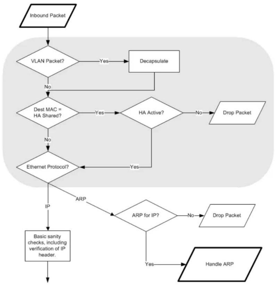
flowchart
graph TD
    A["Inbound Packet"] --> B{VLAN Packet?}
    B -->|Yes| C["Decapsulate"]
    B -->|No| D{Dest MAC = HA Shared?}
    D -->|Yes| E{HA Active?}
    D -->|No| F["Ethernet Protocol?"]
    E -->|No| G["Drop Packet"]
    E -->|Yes| H["ARP for IP?"]
    F --> I["IP"]
    G --> I
    H --> J["Handle ARP"]
    I --> K["Basic sanity checks, including verification of IP header."]
Figure 1.1. Packet Flow Schematic Part I
The packet flow is continued on the following page.
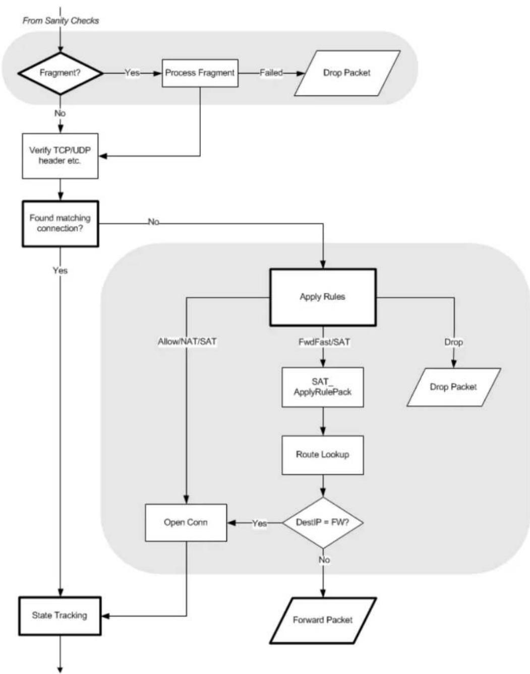
flowchart
graph TD
    A["From Sanity Checks"] --> B{Fragment?}
    B -->|Yes| C["Process Fragment"]
    B -->|No| D["Verify TCP/UDP header etc."]
    C --> E["Find matching connection?"]
    D --> E
    E --> F{Apply Rules}
    F -->|Yes| G["Allow/NAT/SAT"]
    F -->|No| H["Drop Packet"]
    G --> I["Sat_ApplyRulePack"]
    I --> J["Route Lookup"]
    J --> K{DestIP = FW?}
    K -->|Yes| L["Open Conn"]
    K -->|No| M["Forward Packet"]
    L --> N["State Tracking"]
    M --> N
Figure 1.2. Packet Flow Schematic Part II
The packet flow is continued on the following page.
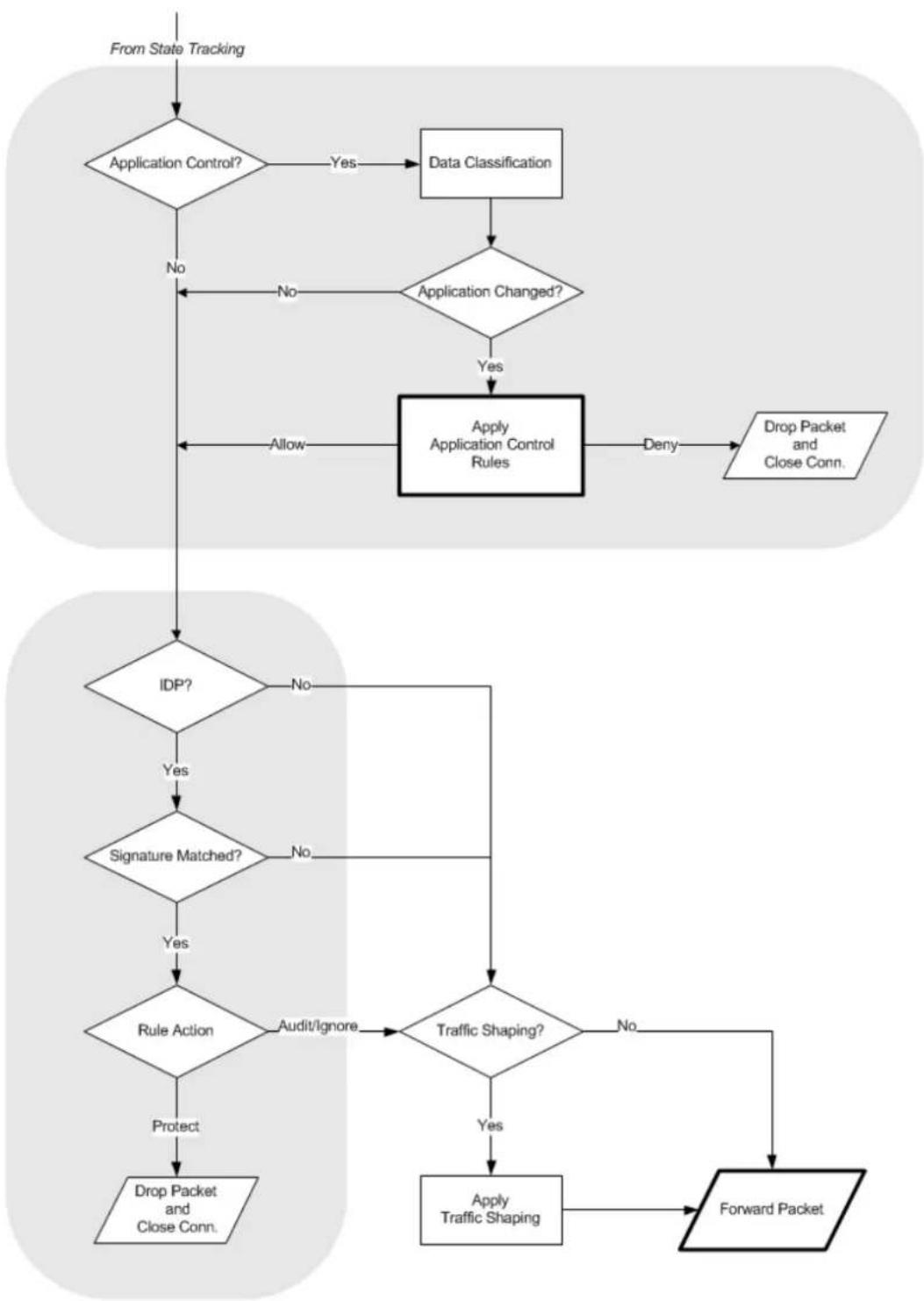
flowchart
graph TD
    A["From State Tracking"] --> B{Application Control?}
    B -->|Yes| C["Data Classification"]
    B -->|No| D{Application Changed?}
    C --> D
    D -->|Yes| E["Apply Application Control Rules"]
    D -->|No| F["Allow"]
    E --> G["Deny"]
    G --> H["Drop Packet and Close Conn."]
    I["IDP?"] --> J{Signature Matched?}
    J -->|Yes| K["Write Off"]
    J -->|No| L["Write Off"]
    K --> M{Rule Action}
    L --> N{Rule Action}
    M --> O["Audit/Ignore"]
    N --> P{Traffic Shaping?}
    P -->|Yes| Q["Apply Traffic Shaping"]
    P -->|No| R["End"]
    O --> S["Forward Packet"]
    T["Protect"] --> U["Drop Packet and Close Conn."]
Figure 1.3. Packet Flow Schematic Part III
Apply Rules
The figure below presents the detailed logic of the Apply Rules function in Figure 1.2, "Packet Flow Schematic Part II" above.
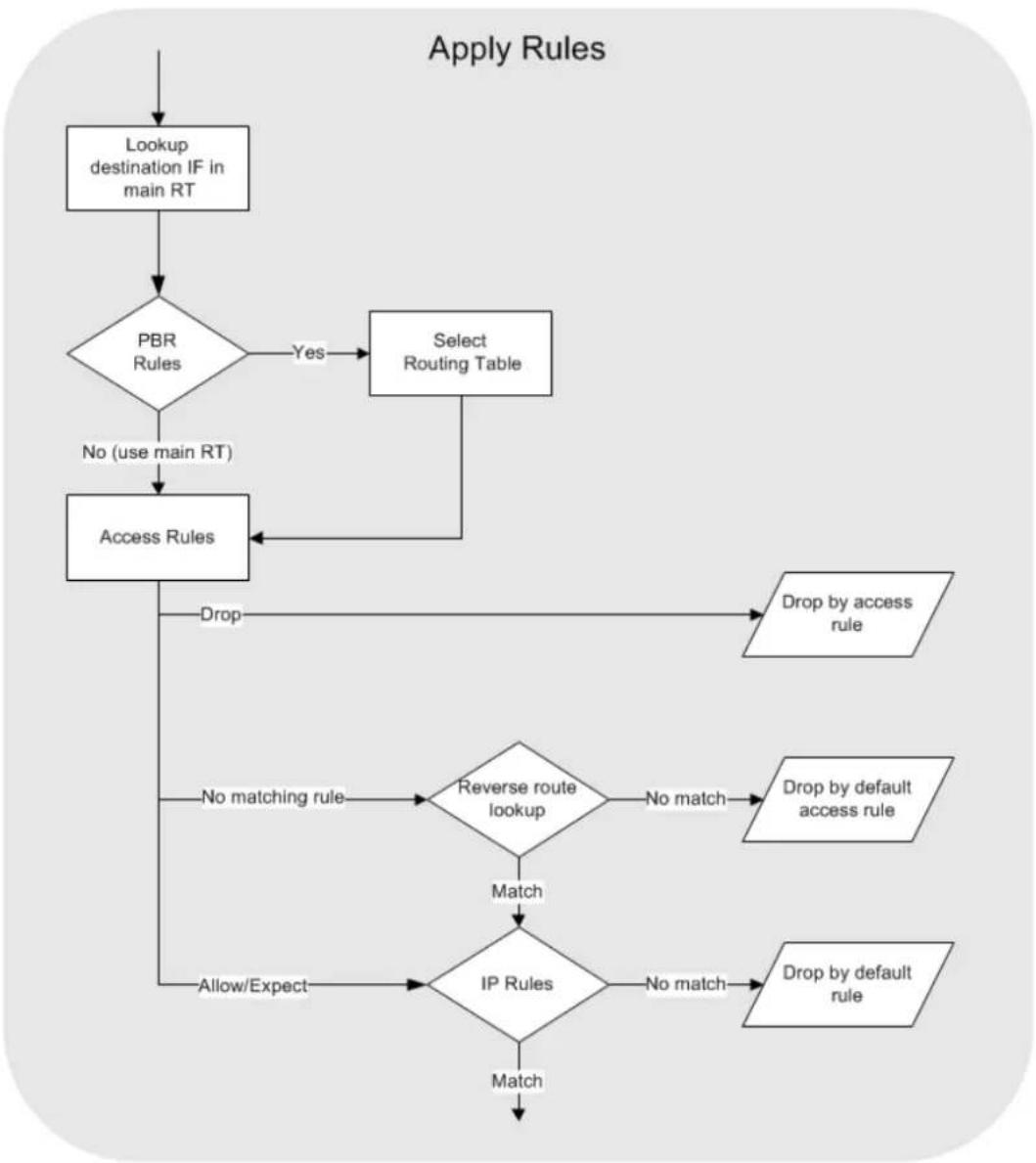
flowchart
graph TD
    A["Lookup destination IF in main RT"] --> B{PBR Rules}
    B -->|Yes| C["Select Routing Table"]
    B -->|No| D["Access Rules"]
    C --> D
    D --> E{Drop}
    E --> F["Drop by access rule"]
    E --> G{No matching rule}
    G --> H{Reverse route lookup}
    H -->|No match| I["Drop by default access rule"]
    H -->|Match| J{IP Rules}
    J -->|No match| K["Drop by default rule"]
    J -->|Match| L["End"]
    H --> M["Allow/Expect"]
    M --> N["End"]
Figure 1.4. Expanded Apply Rules Logic
Chapter 2: Management and Maintenance
This chapter describes the management, operations and maintenance related aspects of NetDefendOS.
- Managing NetDefendOS, page 34
• System Date and Time, page 81
• Events and Logging, page 88
• Monitoring, page 104
• SNMP, page 112
• Diagnostic Tools, page 119 - Maintenance, page 137
• Languages, page 143
• Diagnostics and Improvements, page 144
2.1. Managing NetDefendOS
2.1.1. Overview
NetDefendOS is designed to give both high performance and high reliability. Not only does it provide an extensive feature set, it also enables the administrator to be in full control of almost every detail of the system. This means the product can be deployed in the most challenging environments.
A good understanding on how NetDefendOS configuration is performed is crucial for proper usage of the system. For this reason, this section provides an in-depth presentation of the configuration subsystem as well as a description of how to work with the various management interfaces.
Management User Interfaces
NetDefendOS provides the following management interfaces:
- Web Interface
The Web Interface (also known as the Web User Interface or WebUI) is built into NetDefendOS and provides a user-friendly and intuitive graphical management interface, accessible from a standard web browser.
The browser connects to one of the hardware's Ethernet interfaces using HTTP or HTTPS (by default, only HTTPS is enabled) and NetDefendOS responds like a web server, allowing web pages to be used as the management interface.
By default with NetDefendOS, Web Interface access is enabled for users on the network connected via the LAN interface of the D-Link firewall (on products where more than one LAN interface is available, LAN1 should be used as the default interface).
This feature is described further in Section 2.1.4, "The Web Interface".
• The CLI
The Command Line Interface (CLI), accessible via the local console port or remotely using the Secure Shell (SSH) protocol, provides the most fine-grained control over all parameters in NetDefendOS.
This feature is described further in Section 2.1.5, "CLI Access" and Section 2.1.6, "Using the CLI".
- Secure Copy
Secure Copy (SCP) is a widely used communication protocol for file transfer. No specific SCP client is provided with NetDefendOS distributions but there exists a wide selection of SCP clients available for nearly all workstation platforms.
SCP is a complement to CLI usage and provides a secure means of file transfer between the administrator's workstation and the firewall. Various files used by NetDefendOS can be both uploaded and downloaded with SCP.
This feature is described further in Section 2.1.8, "Secure Copy".
• The Console Boot Menu
Before NetDefendOS starts running, a console connected directly to the D-Link firewall's local console port can be used to do basic configuration through the boot menu. This menu can be entered by pressing any console key between power-up and NetDefendOS starting. It is the D-Link firmware loader that is being accessed with the boot menu.
This feature is described further in Section 2.1.9, "The Console Boot Menu".
Access to the Web Interface can be permitted for administrative users on a certain network, while at the same time allowing CLI access for a remote administrator connecting through a specific IPsec tunnel.
All management access requires that a Remote Management object exists to allow that access. The predefined Remote Management objects and how to create new ones are described in the next section.
2.1.2. Configuring Management Access
Management access to NetDefendOS by an administrator depends on two factors:
- The IP address assigned to the default management Ethernet interface. This IP address can be changed as long as the new IP still belongs to the network that is allowed by the relevant Remote Management object.
- What kind of access the configuration's set of Remote Management objects allow. These objects determine the interface on which management access is permitted, what type of access is allowed via that interface, and which source IP addresses the access can originate from.
The Default Interface and IP for Management Access
The default management interface chosen by NetDefendOS can be different depending on the hardware but is usually the first one found by NetDefendOS when the available interfaces are first scanned on initial startup.
NetDefendOS assigns the default IPv4 address 192.168.10.1 to this management interface and HTTPS access is allowed from the 192.168.10.0/24 network. The interface and IP address assignments are summarized in the table below.
| Hardware Management Interface Default IP Address | ||
| DFL-260E LAN 192.168.10.1 | ||
| DFL-860E LAN 192.168.10.1 | ||
| DFL-870 | LAN1 | 192.168.10.1 |
| DFL-1660 LAN1 | 192.168.10.1 | |
| DFL-2560 LAN1 | 192.168.10.1 | |
| DFL-2560G | LAN1 | 192.168.10.1 |
Remote Management Objects
Remote access over a network to NetDefendOS is controlled by a set of Remote Management objects and these objects can be any of the following types:
- HTTP/HTTPS Management
A predefined object of this type called rmgmt_http already exists in the default NetDefendOS configuration for IPv4 access. A new Remote Management object must be created to allow HTTP/HTTPS management access using an IPv6 address and this is further described later in this section.
- SSH Management
This object type controls access via an SSH client.
• SNMP Management
This object type controls access via an SNMP client. No object of this type exists in the default NetDefendOS configuration and one must be created to allow this kind of access.
SNMP access is discussed further in Section 2.5, "SNMP".
As mentioned above, the following Remote Management objects are already predefined in NetDefendOS:
- rmgmt\_http
This is a RemoteMgmtHTTP object which controls HTTP and HTTPS access via the Web Interface. By default, only HTTPS is allowed from the 192.168.1.0/24 network on the default management interface.
- rmgmt\_ssh
This is a RemoteMgmtSSH object that controls SSH access via the CLI. This is enabled by default and allows SSH access from the 192.168.1.0/24 network on the default management interface.
For other types of access, such as SNMP access, additional Remote Management objects must be created.
Configuring IPv6 Management Access
It is possible for administrator access via HTTP/HTTPS to be configured using IPv6. To do this the following steps are needed:
- Create a new Remote Management object that has an IPv6 address object set for its Network filter.
- Enable IPv6 for the interface specified in the Remote Management object and assign an IPv6 address to that interface.
Preventing Loss of Management Access
When the IP address of the management interface or a remote management rule is changed, there is a risk that the change can prevent further management access. NetDefendOS prevents this in the following ways:
• Changes made through the Web Interface
For configuration changes to the Web Interface, there is a delay after performing a Save and Activate operation (the default is 30 seconds) followed by an automatic check that the web browser and NetDefendOS can still communicate. If communication is lost after the delay, the original configuration is restored.
If the administrator expects that configuration changes will break the communication between NetDefendOS and the web browser (for example, by changing the management IP), they should select Save and Activate then login again before the timeout period expires. This login tells NetDefendOS that the administrator still has access and the configuration will not revert back to the old version.
• Changes made through the CLI over SSH
When using the CLI via an SSH connection, the administrator must first issue the command:
gw-world:/> activate
This activates the new configuration but the changes are not made permanent until the following command is issued:
gw-world:/> commit
If the commit command is not issued within a fixed period of time (the default is 30 seconds) after the activate, NetDefendOS assumes communication has been lost and the original configuration is restored.
If a configuration change breaks SSH communication, the administrator must login in again over SSH in order to issue the commit command and make the changes persistent.
• Changes made via the Local Console CLI
Unlike when using SSH, communication with the local serial console cannot be lost if changing a management interface IP address and/or a remote management rule. This means that a commit command can always be issued after an activate command to make changes persistent. However, the administrator must then check manually if access via the management interface is still possible after entering commit.
If the default 30 second delay is too short, the delay can be changed in the configuration's advanced settings. The setting to change has the name Validation Timeout in the Web Interface and NetconBiDirTimeout in the CLI. It is a global setting.
Example 2.1. Changing the Management Validation Timeout
This example will change the validation timeout from its default value of 30 seconds to 60 seconds.
Command-Line Interface
gw-world:/> set Settings RemoteMgmtSettings NetconBiDirTimeout=60
Web Interface
- Go to: System > Device > Remote Management > Advanced Settings
- Set the following:
- Validation Timeout: 60
- Click OK
An Alternative Method of Changing the Management Interface
An alternative method of changing the management interface, which avoids the 30 second delay entirely, is as follows:
- Login using the existing remote management interface, add a new Remote Management object, then activate and commit the change.
-
Disconnect and then reconnect using the interface specified by the new Remote Management object.
-
Delete the old Remote Management object and the activate and commit the change.
Changing the Management IP Address
The following example shows how the IPv4 address for access on the default management interface can be changed. The new address must belong to the network allowed by the relevant Remote Management object for that interface. If it does not, the object must be changed to allow the IP.
There are two ways of changing the management interface:
- Change the IP address of the interface directly. For example, the CLI for this would be:
gw-world:/> set Interface Ethernet <interface> IP=<ip_address>
This is not recommended since the address object in the address book for this IP address would not change and therefore would any of the other rules and object that refer to it.
- Change the IP address of the address object for the interface IP. This is the recommended method of setting a new management IP address.
Example 2.2. Changing the Management Interface IP Address
This example will change the IPv4 address on the management If1 interface from 192.168.1.1 to 192.168.1.2. Since these belong to the same network, the network or the management policies do not need to be changed.
There are two ways of performing the operation
Command-Line Interface
gw-world:/> set Address IP4Address InterfaceAddresses/If1_ip
IP=192.168.1.2
Web Interface
- Go to: Objects > Address Book
- Select the address folder InterfaceAddresses
- Select the address object If1
- Set the following:
• IP address: 192.168.1.2 - Click OK
Changing a Remote Management Object
If the network as well as the IP address changes for a management interface, and/or a different interface is used, then the relevant management access rule will also need to be changed as shown in the example below.
Example 2.3. Changing a Remote Management Object
This example will change the current HTTP/HTTPS management access to allow access on the If2 interface and from the network defined by the address book object management_net which is already defined. Connection with both HTTP and HTTPS connection will be allowed.
Command-Line Interface
gw-world:/> set RemoteManagement RemoteMgmtHTTP rmgmt_http
HTTP=Yes
HTTPS=Yes
Network=management_net
Interface=If2
Web Interface
-
Go to: System > Device > Remote Management > rmgmt_http
-
Set the following:
-
Enable HTTP
- Enable HTTPS
-
Interface: If2
• Network: management_net -
Click OK
HA Cluster Management IPs Must Be Different
In a NetDefendOS high availability cluster, the management IPs should always be different on the master and slave units for their management interfaces. The shared IP address cannot be used for NetDefendOS management.
The individual IPv4 addresses for the management interface of the cluster master and slave units are held in the IP4 HA Address object for that interface and this is duplicated on both master and slave units. If the management interface IP in this address object is changed on one unit it will be automatically copied over to the other unit by the synchronization process.
Example 2.4. Changing the HA Management IP Address
This example will change the slave management IP address for the lan interface to 192.168.1.2 for an HA cluster.
Command-Line Interface
gw-world:/> set Address IP4HA lan_ha_ip Address:2=192.168.1.2
Web Interface
- Go to: Objects > Address Book
- Select the address book object. In this case, lan_ha_ip
- Set the following:
• Slave IP Address: 192.168.1.2
- Click OK
When it is activated and committed, this change will be synchronized over to the other unit in the cluster.
Adding Remote Management Objects
Extra management access objects can be added to a configuration. For example, to allow only HTTPS access on the If2 interface using the Web Interface, an additional RemoteMgmtHTTP could be added as shown in the next example.
Example 2.5. Adding Remote Management via HTTPS
This example assumes that a new RemoteMgmtHTTP object is to be added called https_access. This will allow HTTPS access on the If2 interface from any network and use the local database AdminUsers to authenticate the administrator's login credentials.
Command-Line Interface
gw-world:/> add RemoteManagement RemoteMgmtHTTP https_access
Network=all-nets
Interface=If2
LocalUserDatabase=AdminUsers
HTTPS=Yes
Web Interface
- Go to: System > Device > Remote Management > Add > HTTP/HTTPS Management
- Enter a Name for the HTTP/HTTPS remote management rule, in this case https_access
- Enable the HTTPS option
-
Select the following:
-
User Database: AdminUsers
-
Interface: If2
• Network: all-nets -
Click OK
Management Access Failure from an all-nets Route
If any VPN tunnel is set up and management access no longer works as expected, it is possible that there is a problem caused by an all-nets route being added to the main routing table so management traffic gets routed into the tunnel.
To solve this problem, the administrator will need to create a specific route that routes management interface traffic leaving the firewall back to the management sub-network.
2.1.3. Administrator Accounts
By default, NetDefendOS has a local user database, AdminUsers, that contains one predefined administrator account. This account has the username admin with password admin. This account has full administrative read/write privileges for NetDefendOS.

Important
For security reasons, it is recommended to change the default password of the default account as soon as possible after connecting with the D-Link firewall.
Creating Additional Accounts
Extra user accounts can be created as required. Accounts can either belong to the Administrator user group, in which case they have complete read/write administrative access. Alternatively, they can belong to the Auditor user group, in which case they have read-only access.
Only One Administrator Account Can Be Logged In
NetDefendOS does not allow more than one administrator account to be logged in at the same time. If one administrator logs in, then a second or more (using different credentials) will be allowed to login but they will only have audit privileges. In other words, the second or more administrators who login will only be able to read configurations and will not be able to change them.
However, NetDefendOS does allow the same administrator account (in other words, using the same administrator credentials) to be logged in more than once at the same time. This means it is possible, for example, to have a CLI session in progress as an administrator at the same time as also performing administrator management operations through the Web Interface.
2.1.4. The Web Interface
NetDefendOS provides an intuitive Web Interface (WebUI) for management of the system via an Ethernet interface using a standard web browser. This allows the administrator to perform remote management from anywhere on a private network or the Internet using a standard computer without having to install client software.

Note: Recommended web browsers
The recommended browsers to use with the Web Interface are:
• Microsoft Internet Explorer
- Firefox
• Safari
- Chrome
• Opera
Assignment of a Default IP Address
For a new D-Link NetDefend firewall with factory defaults, a default IPv4 address is assigned automatically by NetDefendOS to the hardware's LAN1 interface (or the LAN interface on models without multiple LAN interfaces). The IP address assigned to the management interface is always 192.168.10.1.
Changing the management interface and/or IP address from the default is described in
Section 2.1.2, "Configuring Management Access".
Setting the Management Workstation IP
The default management Ethernet interface of the firewall and the external workstation computer's Ethernet interface must be members of the same logical IP network for communication between them to succeed. Therefore, the connecting Ethernet interface of the workstation should be assigned the following static IP values:
• IP address: 192.168.10.30
- Subnet mask: 255.255.255.0
• Default gateway: 192.168.10.1
The diagram below illustrates management workstation connection via a switch.
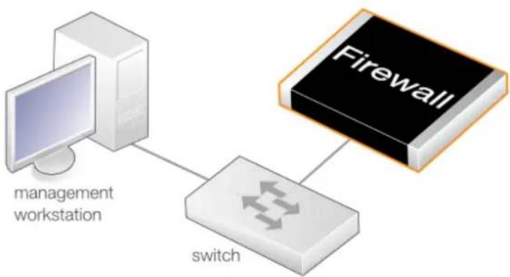
flowchart
graph TD
    A["management workstation"] --> B["switch"]
    B --> C["Firewall"]
Figure 2.1. Management Workstation Connection
Logging on to the Web Interface
To access the Web Interface using the factory default settings, launch a web browser on the external workstation computer and point the browser to the following IPv4 address: 192.168.10.1.
Note that the protocol must be https:// when accessing NetDefendOS for the first time (HTTP can be enabled later. With HTTPS, NetDefendOS will send back its own self-signed certificate for the encryption and the browser will ask the administrator to confirm that a security exception should be made.
When communication with the NetDefendOS is successfully established, a user authentication dialog similar to the one shown below will then be shown in the browser window.
Authentication required
Please enter your username and password
Username: admin
Password: ●●●●●
Language: English

Login

natural_image
Simple grayscale illustration of a padlock with no text or symbolsEnter the username and password and click the Login button. The factory default credentials are as follows:
- Username: admin
- Password: admin
If the entered credentials are correct, NetDefendOS will present the main Web Interface page in the browser.

Note: Password caching is prevented
The Web Interface prevents the caching of the password from the login credentials. This is also done in other NetDefendOS features where a password is requested through a browser screen. For example, with VPN authentication.
First Time Web Interface Login and the Setup Wizard
When logging on for the first time, the default username is always admin and the password is admin.
After successful login, the NetDefendOS Web Interface will be presented in the browser window. If no configuration changes have yet been uploaded to the firewall, the NetDefendOS Setup Wizard will start automatically to take a new user through the essential steps for NetDefendOS setup and establishing Internet access.

Important: Switch off popup blocking
Popup blocking must be disabled in the web browser to allow the NetDefendOS Setup Wizard to run since this appears in a popup window.
The wizard can be terminated and setup up done as a series of separate steps through the Web Interface if desired or alternatively through the CLI.
Multi-language Support
The Web Interface login dialog offers the option to select a language other than English for the interface. Language support is provided by a set of separate resource files. These files can be downloaded from the D-Link website.
It may occasionally be the case that a NetDefendOS upgrade can contain features that temporarily lack a complete non-English translation because of time constraints. In this case the original English will be used as a temporary solution in place of a translation to the selected
language.
The Web Browser Interface
The Web Interface is a allows navigation to the various NetDefendOS subsystems and their related configuration objects. Current NetDefendOS operational information is shown by default.
For information about the default user name and password, see Section 2.1.3, "Administrator Accounts".

Note: Security policies control remote management access
Access to the Web Interface is regulated by the configured remote management policy. By default, the system will only allow web access from the internal network. For more information about this topic, see Section 2.1.2, "Configuring Management Access".
Interface Layout
The main Web Interface page is divided into the following major sections:
- Menu bar
The menu bar located at the top of the Web Interface contains a series of buttons for accessing different aspects of the configuration.
- Object Navigator
The navigator located on the left-hand side of the Web Interface is divided into a number of sections related to the chosen menu bar item.
- Main Window
The main window contains configuration or status details corresponding to the section selected in the menu bar or object navigator.
When displaying tables of information in the main window, right clicking a line (for example, an IP policy) will bring up a context menu.
This context menu can be used to add a new object, delete the current, change the ordering and other operations. The Clone function is used to make a complete copy of the current object and then add it as the last object in the table. Below, is a typical example of the context menu.
| Edit |
| Delete |
| Disable |
| New Group |
| Clone |
| Move to Top |
| Move Up |
| Move to Index |
| Move Down |
| Move to Bottom |

Tip: Hover over textual items for additional information
Many of the textual items in the Web Interface have the ability to present additional information about the item if the screen cursor is held over them. For example, the screenshot below shows the information displayed when the cursor hovers over the Primary Retry Interval field text in the RADIUS settings.

Primary Retry Interval:
How many seconds to wait before trying to use the primary server again if it has failed (0=disable).
Activating Configuration Changes
As configuration changes are made through the Web Interface, they are not applied to the current running configuration until the administrator asks for them to be activated. Activation is done by choosing the Web Interface menu option Configuration > Save and Activate.
NetDefendOS will then perform a reconfigure operation which might cause only a slight, brief delay to current data traffic. To prevent a change locking out the administrator, NetDefendOS will revert to the old configuration if communication is lost with the web browser after a fixed time delay (30 seconds by default). This delay is discussed further in Section 2.1.2, "Configuring Management Access".

Note: Examples in this guide assume activation will be performed
Most of the examples in this guide deal with editing a NetDefendOS configuration. The final activation step is usually not explicitly stated.
Using CA Signed Certificates
By default, when the Web Interface is accessed with HTTPS, a self-signed certificate is sent to the browser which must be explicitly accepted by the user. However, it is possible to use a CA signed
certificate and this can be done with certificate chaining. The next example demonstrates this.
Example 2.6. Remote Management via HTTPS with CA Signed Certificates
Command-Line Interface
gw-world:/> set Settings RemoteMgmtSettings
HTTPSCertificate=HostA
HTTPSRootCertificates=RootA2,RootA1,RootA3
Web Interface
- Go to: System > Device > Remote Management > Advanced Settings
- Under WebUI enter the HTTPS Certificate and the Remote Management certificates.
- Click OK
These same CA signed certificates are also used by the NetDefendOS SSL VPN feature when a user is connecting for the first time and a dialog of options is displayed.

Caution: Do not expose the management interface
The above examples are provided for illustrative purposes only. It is never advisable to expose any management interface to access from the Internet.
Logging out from the Web Interface
After finishing working with the Web Interface, it is advisable to always logout to prevent other users with access to the workstation getting unauthorized access to NetDefendOS. Logout is achieved by clicking on the Logout button at the right of the menu bar.
Management Traffic Routing with VPN Tunnels
If there is a problem with the management interface when communicating alongside VPN tunnels, check the main routing table and look for an all-nets route to the VPN tunnel. Management traffic may be using this route.
If no specific route is set up for the management interface then all management traffic coming from NetDefendOS will automatically be routed into the VPN tunnel. If this is the case then a route should be added by the administrator to route management traffic destined for the management network to the correct interface.
Changing the Device Name
Every D-Link firewall has a Device Name associated with it which is stored on the NetDefendOS configuration. This name appears in the title bar of the Web Interface and also appears in the CLI prompt as well as being displayed in large letters at the top of the Status page of the Web Interface.
By default, this name is always System but this can be changed to another identifier by going to System > Device > Name in the Web Interface. A comment can also be entered along with a
device name.
Changing the device name from the default can be very useful when an administrator is managing multiple firewalls and needs a reminder of which device they are working with.
2.1.5. CLI Access
This section describes the methods for accessing the NetDefendOS Command Line Interface (CLI) and these are:
• Direct access using the local console.
• Network access via an Ethernet interface using SSH.
The authentication aspects of these methods will also be discussed. How the CLI is used is described later in Section 2.1.6, "Using the CLI".
Local Console CLI Access
The local console port is a connection port on the firewall that allows management access to the NetDefendOS CLI through a direct connection to a management workstation. The complete procedure for setting up this connection is described in the relevant D-Link Quick Start Guide. In summary, setup requires the following:
- A management computer or device with the ability to emulate a terminal console.
Appropriate communications software may need to be installed for console emulation and this is available from a number of third parties. - A cable with appropriate connectors to connect the D-Link firewall with the computer.
To connect a terminal to the console port, follow these steps:
- Set the console communication protocol appropriately if required.
- Connect one of the connectors of the cable directly to the local console port on the firewall.
- Connect the other end of the cable to the computer running the console.
- Press the enter key on the terminal console. The NetDefendOS login prompt should appear on the console to indicate successful communication. CLI commands can now be entered.
SSH (Secure Shell) CLI Access
The SSH (Secure Shell) protocol can be used to access the CLI over the network from a remote host. SSH is a protocol primarily used for secure communication over insecure networks, providing strong authentication and data integrity. NetDefendOS supports version 2 of the SSH protocol SSH clients are freely available for almost all hardware platforms.
SSH access is regulated by a remote management policy in NetDefendOS, and SSH access disabled by default. The example below shows how SSH access can be enabled.
Example 2.7. Enabling SSH Remote Access
This example shows how to enable remote SSH access from the lannet network through the lan
interface by adding a rule to the remote management policy.
Command-Line Interface
gw-world:/> add RemoteManagement RemoteMgmtSSH ssh Network=lannet Interface=lan LocalUserDatabase=AdminUsers
Web Interface
- Go to: System > Device > Remote Management > Add > SSH Management
- Enter a Name for the SSH remote management policy, for example ssh_policy
-
Select the following:
-
User Database: AdminUsers
-
Interface: Ian
• Network: lannet -
Click OK
SSH Access Using IPv6
The example above assumes that access from an SSH client will be done using the IPv4 address for an Ethernet interface on the firewall. However, access is also possible using an IPv6 address. The steps required in the NetDefendOS configuration for this are the following:
- IPv6 must be enabled on the Ethernet interface to be used for management connection and an IPv6 address must also be assigned to it. Doing this is described further in Section 3.2, "IPv6 Support".
- A SSH Management rule must be added (as in the previous example) which has its Network property set to the IPv6 network (or host) from which the connection will come.
Automatic Authentication with SSH Keys
By default, SSH access requires a username and password to be entered. An alternative is to authenticate automatically by using SSH keys. This method of authentication is useful when using scripts. It is sometimes referred to as public key authentication.
Authentication in this way requires that the public key file of a public/private key pair is uploaded to NetDefendOS and associated with the relevant User object. Both the public and private key files are installed in the connecting SSH client.
SSH key authentication is enabled with the following steps:
-
Create a suitable set of key files using a third party tool. Key generation can also be done directly within some SSH clients. The key files will consist of a private key file and a public key file. By convention, these are often called id_rsa (the private key) and id_rsa.pub (the public key).
-
Install the key files into the SSH client. This may already have been done if the client was
used to generate the keys.
- Upload the public key file to NetDefendOS using SCP. The file must be stored in the NetDefendOS folder called sshclientkeys (SCP and this folder are described further in Section 2.1.8, "Secure Copy").
The public key file will usually have an original filetype of .pub but the filename on NetDefendOS cannot have a period (".") in the name. If the local filename of the certificate's public key file is id_rsa.pub, this must become something without the period in NetDefendOS storage. For example, it could get the new name my_public_ssh_key and it might be uploaded to NetDefendOS with an SCP client command similar to the following:
> scp id_rsa.pub admin@203.0.113.5:sshclientkeys/my_public_ssh_key
- In NetDefendOS, set the SSH Keys property of the relevant User object to be the uploaded public key file. For example, the user admin could be assigned the key file my_public_ssh_key. This step is described in detail in the example below.
- Connect to NetDefendOS using SSH with key authentication. Authentication will now occur automatically and there will be no prompt for credentials to be entered.
Example 2.8. Enabling SSH Authentication Using SSH Keys
This example shows how to enable automatic SSH authentication for the user admin. It is assumed that an SSH public key file called my_ssh_cert has already been uploaded to NetDefendOS's sshclientkeys folder using SCP.
Command-Line Interface
Change the CLI context to be the user database containing the user:
gw-world:/> cc LocalUserDatabase AdminUsers
Set the SSHKeys property of the relevant user to be the uploaded SSH key file:
gw-world:/AdminUsers> set User admin SSHKeys=my_public_ssh_key
Change the CLI context back to the default:
gw-world:/AdminUsers> cc
gw-world:/>
Web Interface
- Go to: System > Device > Local User Databases
- Select the database AdminUsers
- Select Users
- Select the user admin
- Select SSH Public Key
- Add the my_public_ssh_key to the Selected list
- Click OK
Logging In to the CLI
When access to the CLI has been established to NetDefendOS through the local console or an SSH client, the administrator will need to log on to the system before being able to execute any CLI command. This authentication step is needed to ensure that only trusted users can access the system, as well as providing user information for auditing.
When accessing the CLI remotely through SSH, NetDefendOS will respond with a login prompt. Enter the username and press the Enter key, followed by the password and then Enter again.
After a successful login, the CLI command prompt will appear:
gw-world:/>
If a welcome message has been set then it will be displayed directly after the login. For security reasons, it is advisable to either disable or anonymize the CLI welcome message.
Changing the admin User Password
It is recommended to change the default password of the admin account from admin to something else as soon as possible after initial startup. User passwords can be any combination of characters and cannot be greater than 256 characters in length. It is recommended to use only printable characters.
To change the password to, for example, my-password the following CLI commands are used. First we must change the current category to be the LocalUserDatabase called AdminUsers (which exists by default):
gw-world:/> cc LocalUserDatabase AdminUsers
We are now in AdminUsers and can change the password of the admin user:
gw-world:/AdminUsers> set User admin Password="my-password"
Finally, return the current category to the top level:
gw-world:/AdminUsers> cc

Note: The console password is separate
The password that can be set to protect direct local console access is a separate password and should not be confused with the passwords related to user accounts. The console password is described in Section 2.1.9, "The Console Boot Menu".
2.1.6. Using the CLI
NetDefendOS provides a Command Line Interface (CLI) for administrators who prefer or require a command line approach to administration, or who need more granular control of system configuration. The CLI is available either directly via the local console or remotely via an Ethernet interface using the Secure Shell (SSH) protocol from an SSH client. CLI access is discussed in the preceding Section 2.1.5, "CLI Access".
The CLI provides a comprehensive set of commands that allow the display and modification of configuration data as well as allowing runtime data to be displayed and system maintenance tasks to be performed.
The CLI is case-sensitive. However, the tab-completion feature of the CLI does not require the correct case to perform completion and will alter the typed case if it is required.
This section only provides a summary for using the CLI. For a complete reference for all CLI commands, see the separate D-Link CLI Reference Guide.
The most often used CLI commands are:
- add - Adds an object such as an IP address or a rule to a NetDefendOS configuration.
- set - Sets some property of an object to a value. For example, this might be used to set the source interface on an IP policy.
• show - Displays the current categories or display the values of a particular object.
• delete - Deletes a specific object.
CLI Command Structure
CLI commands normally have the structure:
<command> <object_category> <object_type> <object_name>
For example, to display an IP address object called my_address, the command would be:
gw-world:/> show Address IP4Address my_address
The object category in this case is Address and the type within this category is IPAddress.
When typing commands, the object category can be left out where the command's meaning is unambiguous. For example, the show command above could have been entered as:
gw-world:/> show IPAddress my_address
However, tab completion will always assume the category is included. For example, tab completion would not be able to help complete the above command if the tab is pressed during or after the IPAddress object type.
The same object name could be used within two different categories or types although this is best avoided in order to avoid ambiguity when reading configurations.

Note: The terms Category and Context
When describing the CLI, the terms object category and object context are used interchangeably.
A command like add can also include object properties. To add a new IP4Address object with an IP address of 10.49.02.01, the command would be:
gw-world:/> add IP4Address my_address Address=10.49.02.01
The object type can be optionally preceded by the object category. A category groups together a set of types and mainly used with tab completion which is described below.

Tip: Getting help about help
Typing the CLI command:
gw-world:/> help help
will give information about the help command itself.
The CLI Command History
Just like the console in many versions of Microsoft Windows™, the up and down arrow keys allow the user to move through the list of commands in the CLI command history. For example, pressing the up arrow key once will make the last command executed appear at the current CLI prompt. After a command appears it can be re-executed in its original form or changed first before execution.
Tab Completion
Remembering all the commands and their options can be difficult. NetDefendOS provides a feature called tab completion which means that pressing the tab key will cause automatically completion of the current part of the command. If completion is not possible then pressing the tab key will alternatively display the possible command options that are available.
For example, when creating an IP Policy object, the command line might begin:
gw-world:/> add IPPolicy
If the tab key is now pressed, the mandatory space is inserted and if the tab key is pressed again the mandatory parameters are displayed:
A value is required for the following properties:
DestinationInterface Name SourceInterface
DestinationNetwork Service SourceNetwork
The following might be now be entered, with DestinationInterface incomplete:
gw-world:/> add IPPolicy DestinationI
If the tab key is now pressed, the property name is completed by NetDefendOS to become:
gw-world:/> add IPPolicy DestinationInterface=
Note that completion would not be possible for just Destination because this is still ambiguous and the "I" needs to be added so the first few characters can uniquely identify the property.
The tab key can then be used like this to help complete all the mandatory properties:
gw-world:/> add IPPolicy SourceInterface=If2
SourceNetwork=all-nets
DestinationInterface=If2
DestinationNetwork=all-nets
Service=all_services
Name=my_example_policy

Note: CLI commands in this guide may be reformatted
In order to make the individual elements of CLI commands in this publication clearer, they are sometimes broken into indented separate lines, like the example above. In an actual console window they would appear as a single continuous line which folds at the right margin.
Optional Parameters Are Tab Completed Last
Tab completion does not work with optional parameters until all the mandatory parameters have been entered. Once the mandatory property values have been assigned, using the tab key will list all the optional properties for the IP Policy object:
Optional properties, if no value is specified the default is used:
Action Comments Index Schedule
AppControl DestAddressTranslation LogEnabled SourceAddressTra
Attribute DestinationGeoFilter LogSeverity SourceGeoFilter
Getting the Default or Current Property Value
The period "." character before a tab can be used to automatically fill in the default value for an object property in an Add command. For example:
gw-world:/> add LogReceiver LogReceiverSyslog log_example
Address=example_ip
LogSeverity=.<tab>
This will fill in the default value for LogSeverity:
gw-world:/> add LogReceiver LogReceiverSyslog example
Address=example_ip
LogSeverity=Emergency,Alert,Critical,Error,Warning,Notice,Info
This severity list can then be edited with the back arrow and backspace keys. However, a default value is not always available.
This same sequence can be used to get the current property value in a Set command. For example:
gw-world:/> set LogReceiver LogReceiverSyslog log_example Address=.<tab>
This will display the current value for the Address property.
Appending Property Values
Another usage of the period character before a tab is to automatically fill in the current value of an object property in a command line. This is very useful when there is a need to append a new value to a list of pre-existing values.
For example, the following unfinished command may have been typed:
gw-world:/> set Address IP4Address If1_ip Address=
If a period "." followed by a tab is now entered, NetDefendOS displays the current value for Address. If that value were the IPv4 list 10.6.58.10,192.168.2.1 then the unfinished command line will automatically become:
gw-world:/> set Address IPAddress If1_ip Address=10.6.58.10,192.168.2.1
The displayed values can then be added to or changed with the backspace and back arrow keys before completing the command.
Object Categories
It has been mentioned that objects are grouped by type, such as IP4Address. Types themselves are grouped by category. The type IP4Address belongs to the category Address. The main use of categories is in tab completion when searching for the right object type to use.
If a command such as add is entered and then the tab key is pressed, NetDefendOS displays all the available categories. By choosing a category and then pressing tab again all the object types for that category is displayed. Using categories means that the user has a simple way to specify what kind of object they are trying to specify and a manageable number of options are displayed after pressing tab.
Not all object types belong in a category. The object type UserAuthRule is a type without a category and will appear in the category list after pressing tab at the beginning of a command.
The category is sometimes also referred to as the CLI context. The category does not have to be entered for the command to be valid but always appears when using tab completion. As discussed later, when commands are created automatically using CLI scripting, NetDefendOS omits the category in the commands it creates.
Selecting Object Categories
With some categories, it is necessary to first choose a member of that category with the cc (change category) command before individual objects can be manipulated. This is the case, for example, with routes. There can be more than one routing table, so when adding or manipulating a route we first have to use the cc command to identify which routing table we are interested in.
Suppose a route is to be added to the routing table main. The first command would be:
gw-world:/> cc RoutingTable main
gw-world:/main>
Notice that the command prompt changes to indicate the current category. The route can now be added:
gw-world:/main> add Route Name=new_route1 Interface=lan Network=If1_net
To deselect the category, the command is cc on its own:
gw-world:/main> cc
gw-world:/>
The categories that require an initial cc command before object manipulation have a "/" character following their names when displayed by a show command. For example: RoutingTable/.
Specifying Multiple Property Values
Sometimes a command property may need multiple values. For example, some commands use the property AccountingServers and more than one value can be specified for this property. When specifying multiple values, they should be separated by a comma "," character. For example, if three servers server1, server2, server3 need to be specified then the property assignment in the command would be:
AccountingServers=server1, server2, server3
Inserting into Rule Lists
Rule sets such as the IP rule set have an ordering which is important. When adding using the CLI add command, the default is to add a new rule to the end of a list. When placement at a particular position is crucial, the add command can include the Index= parameter as an option. Inserting at the first position in a list is specified with the parameter Index=1 in an add command, the second position with the parameter Index=2 and so on.
Referencing by Name
The naming of some objects is optional and is done with the Name= parameter in an add command. An object, such as a threshold rule, will always have an Index value which indicates its position in the rule list but can optionally be allocated a name as well. Subsequent manipulation of such a rule can be done either by referring to it by its index, that is to say its list position, or by alternatively using the name assigned to it.
The CLI Reference Guide lists the parameter options available for each NetDefendOS object, including the Name= and Index= options.
Using Unique Names
For convenience and clarity, it is recommended that a name is assigned to all objects so that it can be used for reference if required. Reference by name is particularly useful when writing CLI scripts. For more on scripts see Section 2.1.7, "CLI Scripts".
The CLI will enforce unique naming within an object type. For reasons of backward compatibility to earlier NetDefendOS releases, an exception exists with IP rules which can have duplicate names, however it is strongly recommended to avoid this. If a duplicate IP rule name is used in two IP rules then only the Index value can uniquely identify each IP rule in subsequent CLI commands. Referencing an IP rule with a duplicated name will fail and result in an error message.
Changing the CLI Prompt and Device Name
The default CLI prompt is:
gw-world:/>
where Device is the model number of the D-Link firewall. This can be customized, for example, to my-prompt:/, by using the following CLI command:
gw-world:/> set device name="my-prompt"
The CLI Reference Guide uses the command prompt gw-world:/> throughout.

Tip: The CLI prompt is the Web Interface device name
When the command line prompt is changed to a new string value, this string also appears as the new device name in the top level node of the Web Interface navigation tree.
Activating and Committing Changes
If any changes are made to the current configuration through the CLI, those changes will not be uploaded to NetDefendOS until the command:
gw-world:/> activate
is issued. Immediately following the activate command, the command:
gw-world:/> commit
should be issued to make those changes permanent.

Note: Examples in this guide assume activation will be performed
Most of the examples in this guide deal with editing a NetDefendOS configuration. The final activation step is usually not explicitly stated.
If the commit command is not entered after a activate command within a given time period (the default is 30 seconds) then the changes are automatically undone and the old configuration restored. This topic is discussed further in Section 2.1.2, "Configuring Management Access".

Note: CLI commits terminate Web Interface sessions
There is a possible side effect of committing changes through the CLI. Any Web Interface browser session that is logged in at the time of the commit will require that the user logs in again. This is because the Web Interface view of the configuration may no longer be valid.
Restarting and Rebooting NetDefendOS with the CLI
The CLI can be used to reboot NetDefendOS using the command:
This command performs a graceful shutdown of all connections and VPN tunnels before the restart and is sufficient for most situations that require a system restart. It includes a reloading of the configuration (in other words, a reconfiguration operation).
The shutdown command can be followed by an integer between 0 and 60 which is a delay in seconds before the command is executed. For example:
gw-world:/> shutdown 30
The default value for the delay is 5 seconds.
To shut down and restart both NetDefendOS and completely reinitialize the hardware, including the NetDefendOS loader (equivalent to switching the hardware off then on), use the command:
gw-world:/> shutdown -reboot
The -reboot option is rarely needed in normal circumstances and because it requires more time for the restart it is best not to use it. When NetDefendOS is upgraded the -reboot option is executed automatically during the upgrade process.
The same restart functions can be performed with the Web Interface by selecting the option
Status > Maintenance > Reset & Restore > Restart.
Reconfiguring NetDefendOS with the CLI
NetDefendOS can be forced to reread and reload the current configuration with the command:
gw-world:/> reconf
Apart from reloading the configuration, many of NetDefendOS's internal data structures related to rules and traffic processing are reinitialized. It is not usual to execute a reconfigure during normal operation but it can sometimes be a way to solve transient problems related to NetDefendOS memory management.
Unlike the system restart described above, a reconfiguration does not usually affect current connections or VPN tunnels. However, with some IPsec tunnel changes, a reconfiguration will mean the tunnels are lost and have to be re-established because the tunnel SAs are no longer valid.
Checking Configuration Integrity
After changing a NetDefendOS configuration and before issuing the activate and commit commands, it is possible to explicitly check for any problems in a configuration using the command:
gw-world:/> show -errors
This will cause NetDefendOS to scan the configuration about to be activated and list any problems. A possible problem that might be found in this way is a reference to an IP object in the address book that does not exist in a restored configuration backup.
Logging off from the CLI
After finishing working with the CLI, it is recommended to logout in order to avoid letting anyone getting unauthorized access to the system. Log off by using the exit or the logout command.
Configuring Remote Management Access on an Interface
Remote management access may need to be configured through the CLI. Suppose management access is to be through Ethernet interface If2 which has an IP address 10.8.1.34.
Firstly, we set the values for the IPv4 address objects for If2 which already exist in the NetDefendOS address book, starting with the interface IP:
gw-world:/> set Address IP4Address InterfaceAddresses/If2_ip Address=10.8.1.34
The network IP address for the interface must also be set to the appropriate value:
gw-world:/> set Address IP4Address InterfaceAddresses/If2_net
Address=10.8.1.0/24
In this example, local IP addresses are used for illustration but these could be public IPv4 addresses instead. It is also assumed that the default address objects for the configuration are stored in an address book folder called InterfaceAddresses.
Next, create a remote HTTP management access object, in this example called HTTP_If2:
gw-world:/> add RemoteManagement RemoteMgmtHTTP HTTP_If2
Interface=If2
Network=all-nets
LocalUserDatabase=AdminUsers
AccessLevel=Admin
HTTP=Yes
If we now activate and commit the new configuration, remote management access via the IPv4 address 10.8.1.34 is now possible using a web browser. If SSH management access is required then a RemoteMgmtSSH object should be added.
The assumption made with the above commands is that an all-nets route exists to the ISP's gateway. In other words, Internet access has been enabled for the firewall.
Managing Management Sessions with sessionmanager
The CLI provides a command called sessionmanager for managing management sessions themselves. The command can be used to manage all types of management sessions, including:
• Secure Shell (SSH) CLI sessions.
• Any CLI session through the local console interface.
- Secure Copy (SCP) sessions.
• Web Interface sessions connected by HTTP or HTTPS.
The command without any options gives a summary of currently open sessions:
gw-world:/> sessionmanager
Session Manager status
----
Active connections : 3
Maximum allowed connections : 64
Local idle session timeout : 900
NetCon idle session timeout : 600
To see a list of all sessions use the -list option. Below, is some typical output showing the local console session:
gw-world:/> sessionmanager -list
User Database IP Type Mode Access
____ ____ ____
local <empty> 0.0.0.0 local console admin
If the user has full administrator privileges, they can forcibly terminate another management session using the -disconnect option of the sessionmanager command.
The sessionmanager command options are fully documented in the CLI Reference Guide.
2.1.7. CLI Scripts
To allow the administrator to easily store and execute sets of CLI commands, NetDefendOS provides a feature called CLI scripting. A CLI script is a predefined sequence of CLI commands which can be executed after they are saved to a file and the file is then uploaded to the D-Link firewall.
The steps for creating a CLI script are as follows:
- Create a text file with a text editor containing a sequential list of CLI commands, one per line.
The D-Link recommended convention is for these files to use the file extension .sgs (Security Gateway Script). The filename, including the extension, should not be more than 12 characters.
- Upload the file to the D-Link firewall using Secure Copy (SCP). There are a number of third party software products that can provide SCP on various computer platforms. Script files must be stored in a directory below the root called script. For example, a typical SCP console command for uploading might be:
> scp my_script.sgs admin1@10.5.62.11:script/
SCP uploading is discussed further in Section 2.1.8, "Secure Copy".
- Use the CLI command script -execute to run the script file.
The CLI script command is the tool used for script management and execution. The complete syntax of the command is described in the CLI Reference Guide and specific examples of usage are detailed in the following sections. See also Section 2.1.6, "Using the CLI".

Note: Uploaded scripts are lost after a restart
Uploaded CLI script files are not held in permanent memory and will disappear after system restarts.
Only Four Commands are Allowed in CLI Scripts
The commands allowed in a script file are limited to four and these are:
- add
- set
- delete
• cc
If any other command appears in a script file it is ignored during execution and a warning message is output. For example, the ping command will be ignored.
Executing Scripts
As mentioned above, the script -execute command launches a named script file that has been previously uploaded to the firewall. For example, to execute the script file my_script.sgs which has already been uploaded, the CLI command would be:
gw-world:/> script -execute -name=my_script.sgs
Script Variables
A script file can contain any number of script variables which are called:
1,2, 3,4......$n
The values substituted for these variable names are specified as a list at the end of the script -execute command line. The number n in the variable name indicates the variable value's position in this list. \1 comes first, \2 comes second and so on.

Note: The symbol \$0 is reserved
Notice that the name of the first variable is \1. The variable \0 is reserved and is always replaced before execution by the name of the script file itself.
For example, a script called my_script.sgs is to be executed with IP address 126.12.11.01 replacing all occurrences of \1 in the script file and the string If1 address replacing all occurrences of \2.
The file my_script.sgs contains the single CLI command line:
add IP4Address If1_ip Address=1 Comments=2
To run this script file after uploading, the CLI command would be:
gw-world:/> script -execute -name=my_script.sgs 126.12.11.01 "If1 address"
When the script file runs, the variable replacement would mean that the file becomes:
add IP4Address If1_ip Address=126.12.11.01 Comments="If1 address"
Escaping Characters
Sometimes, there is a requirement to escape certain characters in a command so they are treated as ordinary characters when the command is executed. This is particularly true for the dollar-sign "\" character. Consider the string: "te\t". In order to have the dollar-sign treated as a normal character, it can be escaped in the normal way by using a backslash "\" character. The string would become "te\st" and the dollar-sign is no longer treated as special.
Script Validation and Command Ordering
CLI scripts are not, by default, validated. This means that the written ordering of the script does not matter. There can be a reference to a configuration object at the beginning of a script which is only created at the end of the script.
Although this approach might seem illogical, it is done to improve the readability of scripts. If something always has to be created before it is referred to then this can result in confused and disjointed script files and in large script files it is often preferable to group together related CLI commands.
Error Handling
If an executing CLI script file encounters an error condition, the default behavior is for the script to terminate. This behavior can be overridden by using the -force option.
For example, to run a script file called my_script2.sgs in this way so that errors do not terminate execution, the CLI command would be:
gw-world:/> script -execute -name=my_script2.sgs -force
If -force is used, the script will continue to execute even if errors are returned by a command in the script file.
Script Output
Any output from script execution will appear at the CLI console. Normally this output only consists of any error messages that occur during execution. To see the confirmation of each command completing, the -verbose option should be used:
gw-world:/> script -execute -name=my_script2.sgs -verbose
Saving Scripts
When a script file is uploaded to the firewall, it is initially kept only in temporary RAM memory. If NetDefendOS restarts then any uploaded scripts will be lost from this volatile memory and must be uploaded again to run. To store a script between restarts, it must explicitly be moved to non-volatile NetDefendOS disk memory by using the script -store command.
For example, to move my_script.sgs to non-volatile memory, the command would be:
gw-world:/> script -store -name=my_script.sgs
Alternatively, all scripts can be moved to non-volatile memory with the command:
gw-world:/> script -store -all
Removing Scripts
To remove a saved script, the script -remove command can be used. For example, to remove the my_script.sgs script file, the command would be:
gw-world:/> script -remove -name=my_script.sgs
Listing Scripts
The script on its own, command without any parameters, lists all the scripts currently available and indicates the size of each script as well as the type of memory where it resides (residence in non-volatile memory is indicated by the word "Disk" in the Memory column).
gw-world:/>script
Name Storage Size (bytes)
____
my_script.sgs RAM 8
my_script2.sgs Disk 10
To list the content of a specific uploaded script file, for example my_script.sgs the command would be:
gw-world:/> script -show -name=my_script.sgs
Creating Scripts Automatically
When the same configuration objects needs to be copied between multiple D-Link firewalls, then one way to do this with the CLI is to create a script file that creates the required objects and then upload to and run the same script on each device.
If we already have a NetDefendOS installation that already has the objects configured that need to be copied, then running the script -create command on that installation provides a way to automatically create the required script file. This script file can then be downloaded to the local management workstation and then uploaded to and executed on other firewalls to duplicate the objects.
For example, suppose the requirement is to create the same set of IP4Address objects on several firewalls that already exist on a single unit. The administrator would connect to the single unit with the CLI and issue the command:
gw-world:/> script -create Address IP4Address -name=new_script.sgs
This creates a script file called new_script_sgs which contains all the CLI commands necessary to create all IP4Address address objects in that unit's configuration. The created file's contents might, for example, be:
add IP4Address If1_ip Address=10.6.60.10
add IP4Address If1_net Address=10.6.60.0/24
add IP4Address If1_br Address=10.6.60.255
add IP4Address If1_dns1 Address=141.1.1.1
    "
    "
    "
The file new_script_sgs can then be downloaded with SCP to the local management workstation and then uploaded and executed on the other D-Link firewalls. The end result is that all units will have the same IP4Address objects in their address book.
The following should be noted for automatically created scripts:
• Automatically created scripts omit the object category.
In the created script example above, adding an IP address is done with the command:
add IP4Address...
This is instead of the usual way of qualifying the object with its category name:
add Address IP4Address...
Both are valid forms of the command. If an object type can be uniquely identified with its name, its object category need not be specified. With automatically generated scripts, this is always the case. This shortened form can also be used when typing the entire command in a CLI console although tab completion will always include the object category.
• The script filename length has a limit.
The name of the file created using the -create option cannot be greater than 16 characters in length (including the extension) and the filetype should always be .sgs.
• Both Set and Add appear in scripts.
The default configuration objects will have a Set action and the objects added to the default configuration will have an Add action.
- Creating scripts for the entire configuration.
It is possible to create a script for the entire configuration with the command:
gw-world:/> script -create -name=entire_config.sgs
This can be useful if the entire configuration is to be recreated.
However, note that the following objects will not be included in a script created for the entire configuration:
i. Added Certificate objects.
ii. Objects marked for deletion.
• Some objects are always excluded from created script files.
Certain aspects of a configuration which are hardware dependent cannot have a script file entry created when using the -create option. This is true when the CLI node type in the script -create command is one of the following:
• COMPortDevice
- Ethernet
- EthernetDevice
- Device
These node types are skipped when the script file is created and NetDefendOS gives the message No objects of selected category or type.

Tip: Listing created script commands on the console
To list the created CLI commands on the console instead of saving them to a file, leave out the option -name= in the script -create command.
Commenting in Script Files
Any line in a script file that begins with the # character is treated as a comment. For example:
<h1 id="the-following-line-defines-the-if1-ip-address-add-ip4address-if1_ip-address1066010">The following line defines the If1 IP address add IP4Address If1_ip Address=10.6.60.10</h1>
Scripts Running Other Scripts
It is possible for one script to run another script. For example, the script my_script.sgs could contain the line:
script -execute -name my_script2.sgs
NetDefendOS allows the script file my_script2.sgs to execute another script file and so on. The maximum depth of this script nesting is 5.
Running Scripts from the Web Interface
It is possible to upload and execute a CLI script through the Web Interface. Following execution of the script, it is not retained in memory.
The script does not need to have a filetype of .sgs for this feature to be used. Any filetype is acceptable.
Example 2.9. Running a CLI Script from the Web Interface
In this example, a CLI script called my_script.sgs on local disk storage is uploaded and executed through the Web Interface.
Web Interface
- Go to: Status > Maintenance > Import Script
- Select Browse and choose the script file my_script.sgs
- Select Upload and Execute
- A message is displayed indicating successful execution
- The changed configuration must now be activated and saved
2.1.8. Secure Copy
To upload and download files to or from the D-Link firewall, the secure copy (SCP) protocol can be used. SCP is based on the SSH protocol and many freely available SCP clients exist for almost all platforms. The command line examples below are based on the most common command format for SCP client software.
SCP Command Format
SCP command syntax is straightforward for most console based clients. The basic command used here is scp followed by the source and destination for the file transfer.
Upload is performed with the command:
> scp <local_filename> <destination_firewall>
Download is done with the command:
> scp <source_firewall> <local_filename>
The source or destination firewall is of the form:
For example: admin@10.62.11.10:config.bak. The

Note: SCP examples do not show the password prompt
SCP will normally prompt for the user password after the command line but that prompt is not shown in the examples given here.
The following table summarizes the operations that can be performed between an SCP client
and NetDefendOS.
| File type Upload possible Download possible | ||
| Configuration Backup (config.bak) | Yes (also with WebUI) | Yes (also with WebUI) |
| System Backup (full.bak) | Yes (also with WebUI) | Yes (also with WebUI) |
| Firmware upgrades Yes No | ||
| Certificates Yes Yes | ||
| SSH public keys Yes No | ||
| Web auth banner files Yes Yes | ||
| Web content filter banner files | Yes | Yes |
NetDefendOS File organization
NetDefendOS maintains a simple two level directory structure which consists of the top level root and a number of sub-directories. However, these "directories" such as sshlclientkey should be more correctly thought of as object types. All the files stored in the NetDefendOS root as well as all the object types can be displayed using the CLI command ls.
The resulting output is shown below:
gw-world:/> ls
HTTPALGBanners/
HTTPAuthBanners/
certificate/
config.bak
full.bak
script/
sshclientkeys/
Apart from the individual files, the objects types listed are:
- HTTPAuthBanners/ - The folder containing the HTML banner files for user authentication. Uploading these is described further in Section 6.2.5, "Customizing WCF HTML Pages".
- HTTPALGBanners/ - The folder containing HTML banner files for HTML ALG dynamic content filtering. Uploading these is described further in Section 6.2.5, "Customizing WCF HTML Pages".
• certificate/ - The folder containing uploaded X.509 digital certificates for VPN. - script/ - The folder containing all CLI scripts. Scripts are described further in Section 2.1.7, "CLI Scripts".
- sshclientkeys/ - The folder containing SSH client public key files that allow automatic authentication from an SSH client which has the matching private key installed.
The filename should not have a filetype (in other words, there should be no period character in the name). After upload, the administrator should associate the file with a User object so that user can have automatic authentication enabled.
SSH authentication with certificates is described further in Section 2.1.5, "CLI Access".
Examples of Uploading and Downloading
In some cases, a file may be located in the NetDefendOS root directory. Configuration backup files (config.bak) and the complete system backup files (full.bak) will be saved to the root
directory.
When uploading, these files contain a unique header which identifies what they are. NetDefendOS checks this header and ensures the file is stored only in the root (all files do not have a header).
If an administrator username is admin1 and the IPv4 address of the D-Link firewall is 10.5.62.11 then to upload a configuration backup, the SCP command would be:
> scp config.bak admin1@10.5.62.11:
To download a configuration backup to the current local directory, the command would be:
> scp admin1@10.5.62.11:config.bak ./
To upload a file to an object type under the root, the command is slightly different. If we have a local CLI script file called my_script.sgs then the upload command would be:
> scp my_script.sgs admin1@10.5.62.11:script/
If we have the same CLI script file called my_scripts.sgs stored on the firewall then the download command would be:
> scp admin1@10.5.62.11:script/my_script.sgs ./
Activating Uploads
Like all configuration changes, SCP uploads only become active after the CLI commands activate have been issued and this must be followed by commit to make the change permanent.
Uploads of firmware upgrades (packaged in .upg files) or a full system backup (full.bak) are the exception. Both of these file types will result in an automatic system reboot. The other exception is for script uploads which do not affect the configuration.
2.1.9. The Console Boot Menu
The NetDefendOS loader is the base software on top of which NetDefendOS runs and the administrator's direct interface to this is called the console boot menu (also known simply as the boot menu). This section discusses the boot menu options.
Accessing the Console Boot Menu
The boot menu is only accessible through a console device attached directly to the serial console located on the D-Link firewall. It can be accessed through the console after the firewall is powered up and before NetDefendOS is fully started.
After powering up the firewall, there is a 3 second interval before NetDefendOS starts up and in that time the message Press any key to abort and load boot menu is displayed as shown below:

If any console key is pressed during these 3 seconds then NetDefendOS startup pauses and the console boot menu is displayed.
Initial Boot Menu Options without a Password Set
When NetDefendOS is started for the first time with no console password set for console access then the full set of boot menu options are displayed as shown below:
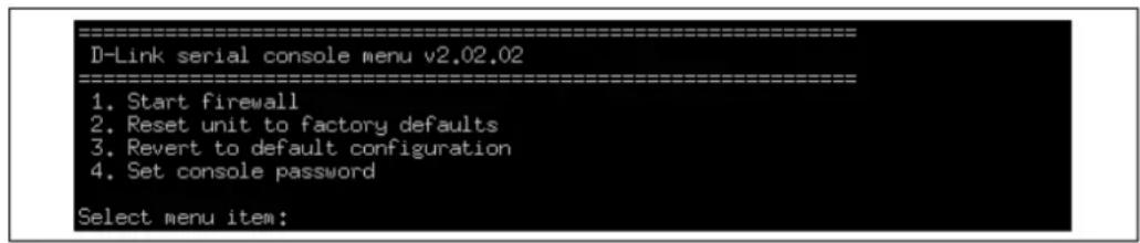
The options available in the boot menu are:
1. Start firewall
This initiates the complete startup of the NetDefendOS software on the firewall.
2. Reset unit to factory defaults
This option will restore the hardware to its initial factory state. The operations performed if this option is selected are the following:
- Remove console security so there is no console password.
- Restore default NetDefendOS executables along with the default configuration.
3. Revert to default configuration
This will only reset the configuration to be the original, default NetDefendOS configuration file. Other options, such as console security, will not be affected.
4. Set console password
Set a password for console access. Until a password is set, anyone can utilize the console so selecting setting the password as soon as possible is recommended. After it is set, the console will prompt for the password before access is allowed to either the boot menu or the command line interface (CLI).
Initial Options with a Console Password Set
If a console password is set then the initial options that appear when NetDefendOS loading is interrupted with a key press are shown below.

The 1. Start firewall option re-continues the interrupted NetDefendOS startup process. If the 2. Login option is chosen, the console password must be entered and the full boot menu described above is entered.
Removing the Console Password
Once the console password is set it can be removed by selecting the Set console password option in the boot menu and entering nothing as the password and just pressing the Enter key to the prompt.
The Console Password is Only for the Console
The password set for the console is not connected to the management username/password combinations used for administrator access through a web browser. It is valid only for console access.
2.1.10. RADIUS Management Authentication
For system management tasks in the default NetDefendOS configuration, the administrator logs in to the Web Interface or CLI via SSH using a username and password that are checked against the credentials stored in a local NetDefendOS database.
An alternative to using a local database is to have NetDefendOS perform authentication of the entered credentials against an external RADIUS server. This is done by changing the properties of the Remote Management object mgmt_http for Web Interface access and/or the properties of the mgmt_ssh object for CLI access via SSH. Configuring either of these objects for RADIUS authentication consists of the following steps:
- Select the Authentication Source property to be RADIUS.
- Select the Authentication Order property to be one of the following:
i. Local First - The login credentials are first looked up in the local user database. If not found in the local database, the configured RADIUS servers are queried.
ii. Local Last - The local database is only queried if none of the configured RADIUS servers responds to an authentication request.
- Select one or more RADIUS servers to use for authentication. If there is more than one, they will be tried sequentially if one is unavailable. The servers selected must have already been configured as Radius Server objects in NetDefendOS (see Section 9.2.3, "External RADIUS Servers" for how to do this).
- Specify the Admin Groups and/or Audit Groups to decide which kind of access will be given once login credentials are authenticated by a RADIUS server. These group names are matched by NetDefendOS against the group name returned for the user by the RADIUS server. Setting either of these properties to the single wildcard character asterisk "*" means any group will get that access. Leaving either property blank means no user can have that type of access.
The administrator group names take precedence over the auditor groups. This means if a user is first authenticated by being a member of the administrator groups, auditor group membership is ignored. Therefore, specifying the asterisk "*" character for the Admin Groups property means that auditor group membership will never be checked.
Note that the wildcard "*" character can be used instead of all or part of a group name. For example, the string sys* means any group name that begins with the three letters sys.
It is important to note that all management users authenticated by a RADIUS server must have their group membership defined on the RADIUS server. They cannot be authenticated without group membership which NetDefendOS matches against the Admin Groups and Audit Groups properties.

Note: Set the RADIUS Vendor ID for group membership
If the RADIUS server is required to send the group membership, it is necessary to use the user group vendor specific attribute vendor when configuring the server. The NetDefendOS Vendor ID is 5089 and the user group is defined as vendor-type 1 with a string value type.
The Login Message Changes for a Group Mismatch
Once set up, the login actions taken by the administrator are the same as with non-RADIUS authentication and there is almost no indication in the Web Interface or in the CLI that RADIUS is being used for authentication.
However, there is one exception. When the user credentials are correct but the group name returned by the RADIUS server does not match any group in the Admin Groups or Audit Groups, then the Web Interface or CLI will display the following message:
You do not have permission to access this device.
Generated Log Event Messages
Log messages indicate a successful or unsuccessful login by the administrator. With RADIUS management authentication, the log message will show the following field values:
- The usergroups field will show a list of all the group memberships returned by the authenticating RADIUS server. This is often helps in troubleshooting why a user was unable to successfully login.
- The access_level indicates the privileges granted for successful authentication.
• The authsource field will have the value RADIUS. - The userdb field will have the value of the RADIUS server object name used.
- The server_ip is the IP of the NetDefendOS interface the client is connecting to. It is not the IP of the authenticating RADIUS server.
- The client_ip is the IP of the computer the user is trying to login from.
Below are some typical examples of log event messages:
- Successful RADIUS Authentication
A successful login with the user being part of the system_admins group:
event=admin_login authsystem=HTTP interface=If1 username=jdoe usergroups=sys_admins access_level=administrator authsource=RADIUS userdb=radius_auth1 server_ip=192.168.1.1 server_port=80
client_ip=192.168.1.30 client_port=6132
• Insufficient Access Rights
The user entered a correct username and password but the group name returned by the RADIUS server (sys_admins in the example below) was not found in either the Admin Groups or Audit Groups lists:
event=admin_authorization_failed action=disallow_admin_access
authsystem=HTTP interface=If1 username=jdoe usergroups=sys_admins
authsource=RADIUS userdb=radius_auth1 server_ip=192.168.1.1
server_port=80 client_ip=192.168.1.30 client_port=6042
- Servers Unreachable
All configured RADIUS servers were unreachable and a timeout condition occurred:
event=admin_authsource_timeout authsystem=HTTP interface=If1 username=jdoe
authsource=RADIUS server_ip=192.168.1.1 server_port=80
client_ip=192.168.1.30 client_port=5987
The Local Console is a Fallback Option
It is possible that the administrator could be locked out from logging on via the Web Interface or the CLI over SSH because a RADIUS server will not authenticate the entered credentials and the local database is not allowed to do it either. In such cases, the local console port on the D-Link firewall can still be used for management access. However, if the password has been set for the local console then that password must still be given to get CLI management access (note that the console password is totally separate from other management passwords).
Example 2.10. Enabling RADIUS Management Authentication
This example will change the current default rule for Web Interface management access so that authentication is performed using two RADIUS servers. It is assumed that the RADIUS server objects are already defined in the configuration and have the names radius_auth1 and radius_auth2 where radius_auth2 is the fallback server in case the other fails to respond.
The Authentication Order will be set to Local First which will mean that the local NetDefendOS database will be consulted first. If the user is not found there then the RADIUS servers will be queried.
All users who are members of the group sys_admins are allowed full access privileges. All other authenticated users will have audit privileges only.
Command-Line Interface
gw-world:/> set RemoteManagement RemoteMgmtHTTP rmgmt_http
    AuthSource=RADIUS
    AuthOrder=LocalFirst
    RadiusServers=radius_auth1,radius_auth2
    AdminGroups=sys_admins
Web Interface
- Go to: System > Device > Remote Management
- Select the rmgmt_http object so that its properties can be edited
- Set Authentication Source to RADIUS
- Set Authentication Order to Local First
- For RADIUS Server, select radius_auth1 and press Include
- Repeat the preceding step, selecting radius_auth2
- Set Admin Groups to be sys_admins
- Click OK
2.1.11. Strong Passwords
To ensure system security, NetDefendOS has a global option to enforce the use of strong passwords for users in any local user databases. This option is only available in NetDefendOS version 11.10.00 and later.
A strong password is defined by NetDefendOS as follows:
• It must be at least 8 characters in length.
• It must not contain significant portions of the username.
• It must comply with at least three of the following four requirements:
i. It must contain at least one lowercase character.
ii. It must contain at least one uppercase character.
iii. It must contain at least one digit (0 to 9).
iv. It must contain at least one non-alphabetic character such as !, \$, # or %.
Enabling Strong Passwords
The strong passwords feature is enabled by default in a new installation of NetDefendOS. However, it can be disabled manually and the NetDefendOS Setup Wizard also provides the option to disable it.
If it is not disabled in the setup wizard then the wizard will require a conforming strong password to be entered to replace the default admin password. If running the setup wizard is skipped and strong passwords is left enabled, NetDefendOS will not allow the configuration to be activated for the first time until the admin password conforms to the strong password rules.
Checking of Strong Passwords
If the strong passwords option is enabled, there are two occasions when passwords are checked for strength:
- When a new user is added to a local user database and the password specified.
- When the password of an existing user is changed.
Apart from the user admin, a fresh NetDefendOS configuration will also have a pre-existing user called audit with the default password audit. The audit user password will remain weak until the administrator changes it to a password that conforms to string password rules listed above.
Upgrading Older NetDefendOS Versions
The strong passwords feature was introduced in NetDefendOS version 11.10.00. If an older NetDefendOS version than this is upgraded to a 11.10 version or later, the strong passwords option is always disabled after the upgrade. The strong passwords option must be manually enabled by the administrator if it is required.
However, all passwords for users created before the upgrade will be flagged as not having strong passwords, even if the strong password option is enabled later. If a weak password for a user from the old configuration is to be made strong then the password for that user should be changed to a strong password after the upgrade. If the strong passwords option is enabled, NetDefendOS will make sure that the new password conforms to the strong password rules when it is entered.
Checking User Password Status
When the user list for a local user database is displayed in the Web Interface, there is a column with the title Strong Password. This has a value of either Yes or No which indicates if the password conforms to the strong password rules or not.
Example 2.11. Disabling Strong Passwords
This example shows how strong passwords are disabled so that they are no longer enforced by NetDefendOS in local user user databases.
Command-Line Interface
gw-world:/> set Settings MiscSettings EnforceStrongPasswords=No
Web Interface
- Go to: System > AdvancedSettings > DeviceSettings > MiscSettings
- Disable the setting: Enforce Strong passwords
- Click OK
2.1.12. Management Advanced Settings
Under the Remote Management section of the Web Interface a number of advanced settings can be found. These are:
SSH Before Rules
Enable SSH traffic to the firewall regardless of configured IP rule set entries.
Default: Enabled
WebUI Before Rules
Enable HTTP(S) traffic to the firewall regardless of configured IP rule set entries.
Default: Enabled
SSH Idle Timeout
Number of seconds of inactivity until the local console user is automatically logged out.
Default: 900
Validation Timeout
Specifies the amount of seconds to wait for the administrator to log in before reverting to the previous configuration.
Default: 30
WebUI HTTP port
Specifies the HTTP port for the Web Interface.
Default: 80
WebUI HTTPS port
Specifies the HTTP(S) port for the Web Interface.
Default: 443
HTTPS Certificate
Specifies which certificate to use for HTTPS traffic. Only RSA certificates are supported.
Default: HTTPS
2.1.13. Working with Configurations
Configuration Objects
The system configuration is built up by Configuration Objects, where each object represents a configurable item of any kind. Examples of configuration objects are routing table entries, address book entries, service definitions, IP rules and so on. Each configuration object has a number of properties that constitute the values of the object.
Object Types
A configuration object has a well-defined type. The type defines the properties that are available for the configuration object, as well as the constraints for those properties. For instance, the IP4Address type is used for all configuration objects representing a named IPv4 address.
Object Organization
In the Web Interface the configuration objects are organized into a tree-like structure based on the type of the object.
In the CLI, similar configuration object types are grouped together in a category. These categories are different from the structure used in the Web Interface to allow quick access to the configuration objects in the CLI. The IP4Address, IP4Group and EthernetAddress types are, for instance, grouped in a category named Address, as they all represent different addresses.
Consequently, Ethernet and VLAN objects are all grouped in a category named Interface, as they are all interface objects. The categories have actually no impact on the system configuration; they are merely provided as means to simplify administration.
The following examples show how to manipulate objects.
Example 2.12. Listing Configuration Objects
To find out what configuration objects exist, you can retrieve a listing of the objects. This example shows how to list all service objects.
Command-Line Interface
gw-world:/> show Service
A list of all services will be displayed, grouped by their respective type.
Web Interface
- Go to: Objects > Services
- A web page listing all services will be presented.
A list contains the following basic elements:
- Add Button - Displays a dropdown menu when clicked. The menu will list all types of configuration items that can be added to the list.
- Header - The header row displays the titles of the columns in the list. The tiny arrow images next to each title can be used for sorting the list according to that column.
- Rows - Each row in the list corresponds to one configuration item. Most commonly, each row starts with the name of the object (if the item has a name), followed by values for the columns in the list.
A single row in the list can be selected by clicking on the row on a spot where there is no hyperlink. The background color of the row will turn dark blue. Right-clicking the row will display a menu which gives the option to edit or delete the object as well as modify the order of the objects.
Example 2.13. Displaying a Configuration Object
The simplest operation on a configuration object is to show the values of its properties. This example shows how to display the contents of a configuration object representing the telnet service.
Command-Line Interface
gw-world:/> show Service ServiceTCPUDP telnet
Property Value
Name: telnet
DestinationPorts: 23
Type: TCP
SourcePorts: 0-65535
SYNRelay: No
PassICMPReturn: No
ALG: <empty>
MaxSessions: 1000
Comments: Telnet
The Property column lists the names of all properties in the ServiceTCPUDP class and the Value column lists the corresponding property values.
Web Interface
- Go to: Objects > Services
- Select the telnet entry in the list
- A web page displaying the telnet service will be presented

Note
When accessing object via the CLI you can omit the category name and just use the type name. The CLI command in the above example, for instance, could be simplified to:
gw-world:/> show ServiceTCPUDP telnet
Example 2.14. Editing a Configuration Object
When the behavior of NetDefendOS is changed, it is most likely necessary to modify one or several configuration objects. This example shows how to edit the Comments property of the telnet service.
Command-Line Interface
gw-world:/> set Service ServiceTCPUDP telnet Comments="Modified Comment"
Show the object again to verify the new property value:
gw-world:/> show Service ServiceTCPUDP telnet
Property Value
Name: telnet
DestinationPorts: 23
Type: TCP
SourcePorts: 0-65535
SYNRelay: No
PassICMPReturn: No
ALG: <empty>
MaxSessions: 1000
Comments: Modified Comment
Web Interface
- Go to: Objects > Services
- Select the telnet entry in the list
- In the Comments textbox, a suitable comment
- Click OK
Verify that the new comment has been updated in the list.

Important: Configuration changes must be activated
Changes to a configuration object will not be applied to a running system until the new NetDefendOS configuration is activated.
Example 2.15. Adding a Configuration Object
This example shows how to add a new IP4Address object, here creating the IPv4 address 192.168.10.10, to the address book.
Command-Line Interface
gw-world:/> add Address IP4Address myhost Address=192.168.10.10
Show the new object:
gw-world:/> show Address IP4Address myhost
Property Value
Name: myhost
Address: 192.168.10.10
UserAuthGroups: <empty>
NoDefinedCredentials: No
Comments: <empty>
Web Interface
- Go to: Objects > Address Book
-
Click on the Add button
-
In the dropdown menu displayed, select IP Address
- In the Name text box, enter myhost
- Enter 192.168.10.10 in the IP Address textbox
- Click OK
- Verify that the new IP4 address object has been added to the list
Example 2.16. Deleting a Configuration Object
This example shows how to delete the newly added IP4Address object.
Command-Line Interface
gw-world:/> delete Address IP4Address myhost
Web Interface
- Go to: Objects > Address Book
- Right-click on the row containing the myhost object
- In the dropdown menu displayed, select Delete
The row will be rendered with a strikethrough line indicating that the object is marked for deletion.
Example 2.17. Undeleting a Configuration Object
A deleted object can always be restored until the configuration has been activated and committed. This example shows how to restore the deleted IP4Address object shown in the previous example.
Command-Line Interface
gw-world:/> undelete Address IP4Address myhost
Web Interface
- Go to: Objects > Address Book
- Right-click on the row containing the myhost object
- In the dropdown menu displayed, select Undo Delete
Listing Modified Objects
After modifying several configuration objects, you might want to see a list of the objects that were changed, added and removed since the last commit.
Example 2.18. Listing Modified Configuration Objects
This example shows how to list configuration objects that have been modified.
Command-Line Interface
gw-world:/> show -changes
Type Object
- IP4Address myhost
* ServiceTCPUDP telnet
A "+" character in front of the row indicates that the object has been added. A "*" character indicates that the object has been modified. A "-" character indicates that the object has been marked for deletion.
Web Interface
- Go to: Configuration > View Changes in the menu bar
A list of changes is displayed
Activating and Committing a Configuration
After changes to a configuration have been made, the configuration has to be activated for those changes to have an impact on the running system. During the activation process, the new proposed configuration is validated and NetDefendOS will attempt to initialize affected subsystems with the new configuration data.

Important: Committing IPsec Changes
The administrator should be aware that if any changes that affect the configurations of live IPsec tunnels are committed, then those live tunnels connections will be terminated and must be re-established.
If the new configuration is validated, NetDefendOS will wait for a short period (30 seconds by default) during which a connection to the administrator must be re-established. As described previously, if the configuration was activated via the CLI with the activate command then a commit command must be issued within that period. If a lost connection could not be re-established or if the commit command was not issued, then NetDefendOS will revert to using the previous configuration. This is a fail-safe mechanism and, amongst others things, can help prevent a remote administrator from locking themselves out.
Example 2.19. Activating and Committing a Configuration
This example shows how to activate and commit a new configuration.
Command-Line Interface
gw-world:/> activate
The system will validate and start using the new configuration. When the command prompt is shown again:
gw-world:/> commit
The new configuration is now committed.
Web Interface
-
Go to: Configuration > Save and Activate in the menu bar
-
Click OK to confirm
The web browser will automatically try to connect back to the Web Interface after 10 seconds. If the connection succeeds, this is interpreted by NetDefendOS as confirmation that remote management is still working. The new configuration is then automatically committed.

Note: Changes must be committed
The configuration must be committed before changes are saved. All changes to a configuration can be ignored simply by not committing a changed configuration.
2.2. System Date and Time
2.2.1. Overview
Correctly setting the date and time is important for NetDefendOS to operate properly. Time scheduled policies, auto-update of the IDP and Anti-Virus databases, and other product features such as digital certificates require that the system clock is accurately set.
In addition, log messages are tagged with time-stamps in order to indicate when a specific event occurred. Not only does this assume a working clock, but also that the clock is correctly synchronized with other equipment in the network.
Methods of Setting the Time
NetDefendOS provides two methods of setting the time:
- Setting Manually
The date and time can be set manually by the administrator. This is described in Section 2.2.2, "Setting Date and Time Manually".
- Setting Automatically Using External Time Servers
NetDefendOS supports the use of external time Servers using time synchronization protocols to automatically adjust the local system clock from the response to queries sent over the Internet to these servers. This is described further in Section 2.2.3, "Using External Time Servers".
There are two types of time server that NetDefendOS can use:
i. Public Servers - These are servers that can be used by anyone.
ii. D-Link Servers - These are D-Link's own time servers and is the recommended method of setting the date and time.
2.2.2. Setting Date and Time Manually
Current Date and Time
The administrator can set the date and time manually and this is recommended when a new NetDefendOS installation is started for the first time.
Example 2.20. Setting the Current Date and Time
To adjust the current date and time, follow the steps outlined below:
Command-Line Interface
gw-world:/> time -set YYYY-mm-DD HH:MM:SS
Where YYYY-mm-DD HH:MM:SS is the new date and time. Note that the date order is year, then month and then day. For example, to set the date and time to 9:25 in the morning on April 27th, 2008 the command would be:
gw-world:/> time -set 2008-04-27 09:25:00
Web Interface
- Go to: System > Device > Date and Time
- Click Set Date and Time
- Set year, month, day and time via the dropdown controls
- Click OK

Note: A reconfigure is not required
A new date and time will be applied by NetDefendOS as soon as it is set. There is no need to reconfigure or restart the system.
Time Zones
The world is divided up into a number of time zones with Greenwich Mean Time (GMT) in London at zero longitude being taken as the base time zone. All other time zones going east and west from zero longitude are taken as being GMT plus or minus a given integer number of hours. All locations counted as being inside a given time zone will then have the same local time and this will have an integer hour offset from GMT.
Setting the Location and Enabling Daylight Saving Time (DST)
For NetDefendOS, the time zone is specified using the Location property of the Date and Time object. NetDefendOS has a database of all available time zones and the administrator just has to pick a place that matches the system's longitude position.
By default, the Location property is set to a value of DLinkHQ (in other words, Taipei time). The DST (daylight saving time) property is also enabled by default which means that the daylight saving rules for the given location will be automatically followed.
The Location property can be changed from the default at any time by the administrator. However, it can also be changed in one of the steps in the Startup Wizard which will run when NetDefendOS is started up for the first time.
Example 2.21. Setting the Time Zone Location
This example will modify the default NetDefendOS time zone to be Tokyo:
Command-Line Interface
gw-world:/> set DateTime Location=Asia/Tokyo
Web Interface
- Go to: System > Device > Date and Time
- In the Location drop-down list, select Asia/Tokyo
- Click OK
2.2.3. Using External Time Servers
NetDefendOS is able to adjust the system time automatically using information received from one or more external time servers. These servers provide a highly accurate time, usually using atomic clocks. Using time servers is recommended as it ensures NetDefendOS will have its date and time aligned with other network devices.
Time Synchronization Protocols
Time Synchronization Protocols are standardized methods for retrieving time information from external time servers. NetDefendOS supports the following such protocols:
• SNTP
Defined by RFC 2030, The Simple Network Time Protocol (SNTP) is a lightweight implementation of NTP (RFC 1305). SNTP is used by NetDefendOS to query time servers. Most public time servers are described as being NTP servers and are accessible using SNTP.
- UDP/TIME
The UDP/TIME protocol is an older method of providing time synchronization service over the Internet. The server sends back the time in seconds since midnight on January 1st, 1900.
Methods of Configuring Time Servers
NetDefendOS provides the ability to configure one of the following two types of time server:
• The D-Link Time Server
D-Link operates its own time server which can be used instead of publicly available servers.
- Custom Time Servers
Specific time servers can be specified. There are a number of publicly available time servers that can be configured.
Configuring these two types of server is described next.
Configuring the D-Link Time Server
A single property exists to switch on or off usage of the D-Link time server. This is the easiest way of configuring a time server since no other server details need to be specified. NetDefendOS will find the IP address of the time server by performing a DNS lookup of the time server's FQDN.
Note that at least one external DNS server must be configured in NetDefendOS so that the FQDN of the D-Link's time server can be resolved.
Example 2.22. Using the D-Link Time Server
To enable the use of the D-Link time server:
Command-Line Interface
gw-world:/> set DateTime TimeSynchronization=D-Link
Web Interface
- Go to: System > Device > Date and Time
- Select D-Link (preconfigured timesync server)
- Click OK
Configuring Custom Time Servers
NetDefendOS can be configured to query multiple external time servers. By using more than a single server, situations where an unreachable server causes the time synchronization process to fail can be prevented. NetDefendOS always queries all configured time servers and then computes an average time based on all responses. Internet search engines can be used to find publicly available time servers.
When specifying the IP address of custom time servers, there are only two ways this can be done:
• Specify an IPv4 or IPv6 address directly.
- Specify an FQDN Address object which contains a reference to the server's URL. At least one external DNS server must also be configured in NetDefendOS to resolve such address objects. This is discussed further in Section 3.1.7, "FQDN Address Objects".
Example 2.23. Configuring Custom Time Servers
In this example, time synchronization is set up to use the SNTP protocol to communicate with the time servers at the Swedish National Laboratory for Time and Frequency. The time server URLs are ntp1.sp.se and ntp2.sp.se.
It is assumed that the following FQDN Address objects have already been defined for the URLs:
- ntp1_fqdn - ntp1.sp.se
- ntp2_fqdn - ntp2.sp.se
Command-Line Interface
gw-world:/> set DateTime TimeSynchronization=custom
TimeSyncServer1=ntp1_fqdn
TimeSyncServer2=ntp2_fqdn
TimeSyncInterval=86400
Web Interface
- Go to: System > Device > Date and Time
- Enable Custom under Time synchronization
- Now enter:
• Time Server Type: SNTP
• Primary Time Server: ntp1_fqdn
• Secondary Time Server: ntp2_fqdn
4. Click OK
Note that the time server URLs must be specified as an FQDN Address object.
Example 2.24. Manually Triggering a Time Synchronization
Time synchronization can be manually triggered from the CLI. The output below shows a typical response.
Command-Line Interface
gw-world:/> time -sync
Attempting to synchronize system time...
Server time: 2008-02-27 12:21:52 (UTC+00:00)
Local time: 2008-02-27 12:24:30 (UTC+00:00) (diff: 158)
Local time successfully changed to server time.
Maximum Time Adjustment
To avoid situations where a faulty time server causes the clock to be updated with an extremely inaccurate time, a Maximum Adjustment value (in seconds) can be set. If the difference between the current NetDefendOS time and the time received from a time server is greater than this maximum adjustment value, then the time server response will be discarded.
For example, assume that the maximum adjustment value is set to 60 seconds and the current NetDefendOS time is 16:42:35. If a time server responds with a time of 16:43:38 then the difference is 63 seconds. This is greater than the maximum adjustment value so no update occurs for this response.
Example 2.25. Modifying the Maximum Adjustment Value
In this example, The maximum adjustment value will be set to 40,000 seconds. This is the maximum time difference that an external server is allowed to adjust for. There may be a valid reason why there is a significant difference such as an incorrect NetDefendOS configuration.
Command-Line Interface
gw-world:/> set DateTime TimeSyncMaxAdjust=40000
Web Interface
- Go to: System > Device > Date and Time
- Set Max drift to 40000
- Click OK
Sometimes it might be necessary to override the maximum adjustment. For example, if time synchronization has just been enabled and the initial time difference is greater than the maximum adjust value. It is then possible to manually force a synchronization and disregard the maximum adjustment parameter.
Example 2.26. Forcing Time Synchronization
This example demonstrates how to force time synchronization, overriding the maximum adjustment setting.
Command-Line Interface
gw-world:/> time -sync -force
Synchronization Intervals
The interval between each synchronization attempt can be adjusted if needed. By default, this value is 86,400 seconds (1 day), meaning that the time synchronization process is executed once in a 24 hour period.
2.2.4. Settings Summary for Date and Time
Below, is a summary of the key properties for date and time:
Time Zone Location
Time zone offset in minutes.
Default: DLinkHQ (Taipei)
DST
Enable daylight saving time (DST) for the selected time zone.
Default: Enabled
Time Sync Server Type
Type of server for time synchronization, UDPTime or SNTP (Simple Network Time Protocol).
Default: SNTP
Primary Time Server
DNS hostname or IP Address of Timeserver 1.
Default: None
Secondary Time Server
DNS hostname or IP Address of Timeserver 2.
Default: None
tertiary Time Server
DNS hostname or IP Address of Timeserver 3.
Default: None
Interval between synchronization
Seconds between each resynchronization.
Default: 86400
Max time drift
Maximum time drift in seconds that a server is allowed to adjust.
Default: 600
Group interval
Interval according to which server responses will be grouped.
Default: 10
2.3. Events and Logging
2.3.1. Overview
The ability to log and analyze system activities is an essential feature of NetDefendOS. Logging enables not only monitoring of system status and health, but also allows auditing of network usage and assists in troubleshooting.
Log Message Generation
NetDefendOS defines a large number of different log messages, which are generated as a result of corresponding system events. Examples of such events are the establishment and teardown of connections, receipt of malformed packets as well as the dropping of traffic according to filtering policies.
Log events are always generated for some aspects of NetDefendOS processing such as buffer usage, DHCP clients, High Availability and IPsec. The generation of events for some NetDefendOS subsystems, such as IP rule set usage, can be disabled or enabled as required.
Whenever an event message is generated, it can be filtered and distributed to all configured Event Receivers. Multiple event receivers can be configured by the administrator, with each event receiver having its own customizable event filter.
2.3.2. Log Messages
Event Types
NetDefendOS defines several hundred events for which log messages can be generated. The events range from high-level, customizable, user events down to low-level and mandatory system events.
The conn_open event, for example, is a typical high-level event that generates an event message whenever a new connection is established, given that the matching security policy rule has defined that event messages should be generated for that connection.
An example of a low-level event would be the startup_normal event, which generates a mandatory event message as soon as the system starts up.
Message Format
All event messages have a common format, with attributes that include category, severity and recommended actions. These attributes enable easy filtering of messages, either within NetDefendOS prior to sending to an event receiver, or as part of the analysis after logging and storing messages on an external log server.
A list of all event messages can be found in the NetDefendOS Log Reference Guide. That guide also describes the design of event messages, the meaning of severity levels and the various attributes available.
Event Severity
The default severity of each log event is predefined and it can be, in order of highest to lowest severity, one of:
- Emergency
- Alert
• Critical - Error
- Warning
- Notice
• Info - Debug
By default, NetDefendOS sends any generated messages of level Info and above to any configured log servers but the level required for sending can be changed by the administrator. The Debug severity is intended for system troubleshooting only and is not normally used. All individual log messages with their meaning are described in the separate NetDefendOS Log Reference Guide.
Event Message Timestamping
When log messages are generated by NetDefendOS for sending to an external log server, they are always timestamped with the time expressed as UTC/GMT (Greenwich Mean Time). This makes it possible to compare events from different firewalls in different time zones which are set with different system times.
The exception to this is log messages which are displayed using the local Memlog feature. These are always timestamped with the current, local system time.
2.3.3. Log Receiver Types
The event messages generated by NetDefendOS can be sent to various types of log receivers. To receive messages, it is necessary to configure in NetDefendOS one or more event receivers objects that specify what events to capture, and where to send them.
NetDefendOS can distribute event messages to different types of receivers and these are enabled by creating any of the following types of Log Receiver objects.
- Memory Log Receiver
NetDefendOS has its own logging mechanism also known as the MemLog. This retains all event log messages in memory and allows direct viewing of recent log messages through the Web Interface.
This is enabled by default but can be disabled.
This receiver type is discussed further below in Section 2.3.4, "The Memory Log Receiver (Memlog)".
- Syslog Receiver
Syslog is the de-facto log message standard for logging events from network devices. If other network devices are already logging to Syslog servers, using Syslog for NetDefendOS log messages can simplify overall administration.
This receiver type is discussed further below in Section 2.3.5, "The Syslog Log Receiver".
- Mail Alerting
The Mail Alerting function allows a number of log messages to be grouped together into a single email which is then sent to a given email address via a designated SMTP server.
This receiver type is discussed further below in Section 2.3.6, "Mail Alerting".
2.3.4. The Memory Log Receiver (Memlog)
Overview
The Memory Log Receiver (also known as Memlog) is a NetDefendOS feature that allows logging direct to memory in the firewall instead of sending messages to an external server. These messages can be examined through the standard user interfaces.
Memlog has Limited Capacity
Memlog memory available for new messages is limited to a fixed predetermined size. When the allocated memory is filled up with log messages, the oldest messages are discarded to make room for newer incoming messages. This means that MemLog holds a limited number of messages since the last system initialization and once the buffer fills they will only be the most recent. This means that when NetDefendOS is creating large numbers of messages in systems with, for example, large numbers of VPN tunnels, the Memlog information becomes less meaningful since it reflects a limited recent time period.
Memlog Timestamps
The timestamp shown is Memlog console output is always the local system time of the firewall. This is different from the timestamp on log messages sent to external log Receivers which are always timestamped with GMT time.
Disabling and Enabling Memlog
A single Memory Log Receiver object exists by default in NetDefendOS and memlog is therefore enabled by default. If logging to memlog is not required then the Memory Log Receiver object can be deleted and this type of logging will not occur. To re-enable memlog, add back the Memory Log Receiver object to the configuration. Only one instance of the Memory Log Receiver can exist at any one time.
2.3.5. The Syslog Log Receiver
Overview
Syslog is a standardized protocol for sending log data although there is no standardized format for the log messages themselves. The format used by NetDefendOS is well suited to automated processing, filtering and searching.
Although the exact format of each log entry depends on how a Syslog receiver works, most are similar. The way in which logs are read is also dependent on how the syslog receiver works. Syslog daemons on UNIX servers usually log to text files, line by line.
Message Format
Most Syslog recipients preface each log entry with a timestamp and the IP address of the machine that sent the log data:
Feb 5 2000 09:45:23 firewall.example.com
This is followed by the text the sender has chosen to send.
Feb 5 2000 09:45:23 firewall.example.com EFW: DROP:
Subsequent text is dependent on the event that has occurred.
In order to facilitate automated processing of all messages, NetDefendOS writes all log data to a single line of text. All data following the initial text is presented in the format name=value. This enables automatic filters to easily find the values they are looking for without assuming that a specific piece of data is in a specific location in the log entry.

Note: The Prio and Severity fields
The Prio= field in SysLog messages contains the same information as the Severity field for D-Link Logger messages. However, the ordering of the numbering is reversed.
Setting the Facility
The Facility property indicates to the server the type of program generating the Syslog message. If not specified, this is set to local0 (meaning a kernel message) by NetDefendOS. The facility name is commonly used as a filtering parameter by most syslog daemons.
Example 2.27. Enable Logging to a Syslog Host
This example enables logging of all events with a severity equal to Emergency or Alert to a Syslog server with the IPv4 address 192.168.6.1.
The facility name will also be set to local1 for this Syslog server.
Command-Line Interface
gw-world:/> add LogReceiver LogReceiverSyslog my_syslog
IPAddress=192.168.6.1
LogSeverity=Emergency,Alert
Facility=local1
Web Interface
- Go to: System > Device > Log Receivers > Add > Syslog Receiver
- Specify a name for the event receiver, in this example my_syslog
- Enter 192.168.6.1 as the IP Address
- Select local1 from the Facility list
- Select SeverityFilter and choose Emergency and Alert as the severities.
- Click OK

Note: The Syslog server itself must be correctly configured
The external Syslog server itself may have to be configured to correctly receive log messages from NetDefendOS. Refer to the documentation for the specific Syslog server being used in order to do this.
RFC 5424 Compliance
By default, NetDefendOS sends Syslog messages in a format that is suitable for most Syslog servers. However, some servers may require stricter adherence to the latest Syslog standard as defined by RFC 5424. For this reason, NetDefendOS provides the option to enable strict RFC 5424 compliance.
Setting the Hostname
In the header of every Syslog message there is a string field which is the Syslog hostname. By default, NetDefendOS always sets this to be the IP address of the sending interface.
If RFC 5424 compliance is enabled, it is also possible to set the hostname to a specific value. The example below shows how this is done.
Example 2.28. Enabling Syslog RFC 5424 Compliance with Hostname
This example enables logging of all events with a severity greater equal to Emergency or Alert to a Syslog server with the IPv4 address 192.168.5.1. RFC 5424 compliance will also be enabled with a hostname of my_host1 in the Syslog header.
Command-Line Interface
gw-world:/> add LogReceiver LogReceiverSyslog my_syslog
IPAddress=192.168.5.1
RFC5424=Yes
Hostname=my_host1
LogSeverity=Emergency,Alert
Web Interface
- Go to: System > Device > Log Receivers > Add > Syslog Receiver
- Specify a name for the event receiver, in this example my_syslog_host
- Enter 192.168.5.1 as the IP Address
- Select an appropriate facility from the Facility list.
- Enable the option RFC 5424 Compliance.
- Enter my_host1 for the Hostname
- Select SeverityFilter and choose Emergency and Alert as the severities.
- Click OK
2.3.6. Mail Alerting
Overview
By creating a Mail Altering object, NetDefendOS can be configured to send log messages in an email to a specified email address via a nominated external SMTP server. The Mail Altering object can be considered to be like other types of log receivers and it is possible to select the type of log messages that are sent.
The intended purpose of this feature is to provide a means of quickly alerting the administrator of any important NetDefendOS events so the selected level of severity for the events sent in this way will usually be very high.
Mail Alerting Object Properties
Many Mail Alerting object properties are the same as in other types of log receiver object and will not be listed again in this section. The object properties that are unique are the following:
- SMTP Server
The IP address of an SMTP server that will forward generated emails to the destination email address. This can also be an FQDN address object or a DNS resolvable FQDN (note that both require that a DNS server is configured in NetDefendOS).
- Server Port
The port number that the SMTP server listens on. This is set by default to the standard port number of 25.
- SMTP Recipient
A single destination email address for outgoing mails.
- SMTP Sender
A string which will be the sender name text in emails.
- Subject
A string which will be the subject text in emails.
- Send Test Email
This is not a property but a button in the Web Interface used to test the SMTP properties entered. It has a CLI equivalent and is explained further later in this section.
Event Trigger Mode
- Single event trigger
A single email is sent for at least each eligible event. The Event count threshold and Event count period values are not used with this option. However, when a single event is ready for sending it must wait for the Keep collecting before sending period so other eligible events can be added to the mail.
- Rate of events trigger
Multiple events are collected together into each email sent. The number of events collected before email sending is controlled by the values of the Event count threshold and Event count period properties.
• Event count threshold
An email is only sent if this number of events has occurred over the preceding number of minutes specified by the Event count period property. The trigger is therefore a given rate of events and not just an accumulation of events. Events that have already been included in a sent email are not counted again.
When a Mail Alerting object is first created, this count is zero and is always reset to zero when NetDefendOS restarts. When an email is sent by the Mail Alerting, object, this count is also reset to zero.
This property and the property Event count period are not used if Single event trigger is selected.
- Event count period
This is the number of minutes referred to in the Event count threshold description above and is the period of recent time in which events are being counted.
- Send report emails
When enabled, an email is always sent at least in the period of time specified by the Report email interval, even if the sent email has no events in it and even if the email is has no events in it or even if (in the case of the Rate of events trigger) the Event count threshold value has not been reached.
This is not used in Single event trigger mode
• Report email interval
This is the maximum length of time in hours that can elapse before an email is sent even though the email might contain no events. Typically, this value might be set to 24 so that the Mail Alerting object generates at least one email a day even though it might be empty. This can inform the administrator that the system is up and highlight any events of interest.
• Report email subject
When a report email is sent, this will be the subject line of the email. This allows the administrator to easily distinguish if an email is a report email or an email generated by a trigger.
The property must have a string value and cannot be left empty.
- Keep collecting before sending
If an email is ready to be sent, NetDefendOS will wait this number of minutes before sending it. Any new events that occur while the email is waiting to be sent are added to the pending email.
This can be used in either triggering mode. If the mode is Single event trigger, any new events during the period after the initial triggering event will be added to the email.
NetDefendOS only sends events in one minute intervals so this means that even is this property is set to zero, there can still be a delay before the email is sent and extra events can still be added during this delay.
• Minimum time between emails
Consecutive sent emails cannot have less than this amount of elapsed time between them. The value of this property can prevent emails being sent too often.
If an email is ready to send but cannot because it is within this period of time, any new events will be added to the email until this period has expired.
Advanced Options
- Identity
This string parameter identifies the SMTP client in the HELO or EHLO command sent to the SMTP server by NetDefendOS. If this property is not set, NetDefendOS will set this automatically to the IPv4 address of the NetDefendOS interface that sends to the SMTP server.
• X-Mailer
This is the name of the software that is communicating with the SMTP server. This is optional and is left blank by default.
Mail Alerting Processing Flow
To better explain the settings for the event trigger properties, consider the following example: a Mail Alerting object has been configured in NetDefendOS and the Multiple events trigger option has been selected with a Event count period value of 2 minutes and an Event count threshold value of 3 events (in other words 3 events must occur in a 2 minute window for an email to be sent).
Assume that since sending its last email, 6 log events occur that are eligible for mailing and these occur over a 6 minute period of time. The diagram below divides the 6 minutes into 2 minute sections for clarity and shows when the events occur.

The processing flow is as follows:
- NetDefendOS starts counting the events from zero before the 1st event.
- The 3rd event occurs, reaching the threshold. However, the 1st event is outside the 2 minute time window and only the 2nd and 3rd events are inside the time period so an email is not sent.
- This is also the case for the 4th and 5th events. There are not enough other events in the previous 2 minutes for either to reach the threshold of 3.
- Only when the 6th event occurs is the threshold of 3 events reached within the previous 2 minutes and an email is sent (after waiting the Keep collecting before sending number of minutes during which time any new log events will be added to the email).
-
NetDefendOS drops the 1st, 2nd and 3rd events so these are not included in the email.
-
The event counter is reset to zero and event counting within the Event count period begins again.
Sending Test Emails
The mail alerting feature has a Send Test Email function to send a test email to the server. This is done by pushing the Send test email button in the Web Interface. In the CLI, a test email is sent with the following command:
gw-world:/> smtp -sendmail -logreceiver=<mail-alerting-object-name>
The body of the test email will contain text which is similar to the following:
This is message #1 sent to test the Mail Alerting object "my_mail_alert"
The number "#1" in the message will increment every time a test mail is sent from this log receiver.
In the Web Interface, the test button can be pushed even while the Mail Alerting object is being created and before the configuration change is activated and saved. This is not true with the equivalent CLI test mail function.
Sending to Multiple Email Addresses
More than one Mail Alerting object can be created so that log messages are sent to multiple email addresses. However, if the same log message information is being sent to multiple email addresses then it is not recommended to create multiple Mail Alerting objects for this purpose. Instead, create a mailing list email address on the SMTP server so that a mail sent to that address is sent to multiple email recipients.
Mail Size Limit
In order to limit the available memory that NetDefendOS uses for buffering log messages and building the email body, a limit is set on the email size. This limit is 8 Kbytes. When this limit is reached but the email had not yet been sent, any new log messages will be dropped. If events are dropped, the following message added to the email body:
message(s) have been discarded because of because of email body size limit
If the available memory is completely used up while building the email, this message will have a slightly different text to indicate that. If message are dropped repeatedly, it is an indication that either the event filter should be made more restrictive or that the emails should be sent more often.
If more than one Mail Alerting object is created, each will have its own piece of memory allocated for building emails.
Example 2.29. Setting up a Mail Alerting Object
This example configures an Mail Alerting object called my_smtp_receiver so that all events with a severity equal to Emergency or Alert are sent out in an email.
It is assumed that the recipient email address is admn@example.com and that the SMTP server address is 203.0.113.10. The default values for the threshold and associated properties are used.
All other configurable properties will be left at their default value.
Command-Line Interface
gw-world:/> add LogReceiver MailAlerting my_mail_alert
IPAddress=203.0.113.10
Receiver=admin@example.com
Sender=device1
Subject="Log message summary"
LogSeverity=Emergency,Alert
Web Interface
-
Go to: System > Device > Event Receivers > Add > Mail Alerting
-
Now enter:
-
Name: my_mail_alert
• SMTP Server: 203.0.113.10 - SMTP Receiver: admin@example.com
-
SMTP Sender: device1
• Subject: Log message summary -
Under SeverityFilter make Emergency and Alert as the selected severities.
-
Click OK
2.3.7. Severity Filter and Message Exceptions
For each log receiver it is possible to impose rules on what log message categories and severities are sent to that receiver. It is also possible to lower or raise the severity of specific events.
The Severity Filter
The Severity Filter is a means of specifying what severities, if any, are sent to the receiver. By default, all log messages except Debug are sent. This can be restricted further so, for example, only Emergency, Alert and Critical messages are sent.
Log Message Exceptions
After the severity filter is applied, any Log Message Exceptions are applied to generated messages. There can be more than one message exception for a log receiver and each consists of the following:
- Category and ID
This specifies the log messages that will be affected by the exception. If the ID number of the log message is not specified then all log messages for the specified category will be included.
The ID of specific log messages can be found in the Log Reference Guide.
- Type
This can be one the following:
i. Exclude - This will exclude the specified log message(s) even if they are allowed by the severity filter.
ii. Include - This will include the specified log message(s) even if they are excluded by the severity filter.
In addition, the Severity of the included message(s) can be specified. If this is set to Default the original severity is used. Otherwise, the severity is set to the specified value. This provides the ability to raise (or lower) the severity of specific log messages.
2.3.8. SNMP Traps
The SNMP protocol
Simple Network Management Protocol (SNMP) is a means for communicating between a Network Management System (NMS) and a managed device. SNMP defines 3 types of messages: a Read command for an NMS to examine a managed device, a Write command to alter the state of a managed device and a Trap which is used by managed devices to send messages asynchronously to an NMS about a change of state.
SNMP Traps in NetDefendOS
NetDefendOS takes the concept of an SNMP Trap one step further by allowing any event message to be sent as an SNMP trap. This means that the administrator can set up SNMP Trap notification of events that are considered significant in the operation of a network.
The file DLINK-DFL-TRAPS-MIB.mib defines the SNMP objects and data types that are used to describe an SNMP Trap received from NetDefendOS.
This file is contained within NetDefendOS itself and can be extracted to a management workstation's local disk either using the Web Interface or Secure Copy (SCP). Doing this is described further in Section 2.5, "SNMP".
For each D-Link firewall model there is one generic trap object called DLNNNosGenericTrap, that is used for all traps (where NNN indicates the model number). This object includes the following parameters:
• System - The system generating the trap.
• Severity - Severity of the message.
• Category - What NetDefendOS subsystem is reporting the problem
• ID - Unique identification within the category.
• Description - A short textual description.
• Action - What action is NetDefendOS taking.
This information can be cross-referenced to the separate Log Reference Guide using the ID.
Using SNMP2c or SNMPv3
NetDefendOS supports the sending of SNMP traps using either SNMP2c or SNMPv3. These SNMP protocol versions are very similar except that SNMPv3 can provide encryption and/or authentication and is therefore the preferred version from a security standpoint.
Configuring Event Receivers
The SNMP trap feature is configured by defining either an SNMP2c Event Receiver or an SNMPv3 Event Receiver object.
Repeat Count
Both the SNMP2c and SNMPv3 log receiver objects have a property called Repeat Count which specifies how many times any single event will be sent to the receiver. The default value for this is zero which means that every time a particular event occurs, a message will be sent to the receiver.
If, for example, the Repeat Count property is set to 3 then a particular event will be sent only for the first three times that it occurs since the last system startup (a system restart will initialize the count). This can prevent a constantly repeating event sending an unnecessary quantity of the same message to the receiver.
Interface Up/Down Events
Both the SNMP2c and SNMPv3 log receiver objects have a property called Use interface link up/down traps which can be disabled or enabled and is disabled by default. If enabled, any change in the online or offline status of any Ethernet interface in the configuration will cause an event to be sent to the receiver.
SNMPv3 Security Options
When using SNMPv3, there are three levels of security that can be chosen:
- noAuthNoPriv - This disables both authentication and encryption (the default).
- authNoPriv - This enables authentication using SHA-1 but disables encryption. Authentication is performed using the Password property which must be specified.
- authPriv - This enables authentication using SHA-1 and enables encryption using AES. Authentication and encryption are performed using the Password property which must be specified.
Example 2.30. Configuring an SNMPv3 Event Receiver
This example configures an SNMPv3 Event Receiver receiver in NetDefendOS that will receive SNMP traps for all events with a severity of Emergency or Alert
Both authentication and encryption will be enabled and the receiver is assumed to have an IPv4 address of 192.168.3.1.
Command-Line Interface
gw-world:/> add LogReceiver EventReceiverSNMPv3 my_snmp_receiver
IPAddress=192.168.3.1
Username=my_name
Password=myunguessablepassword
Snmp3SecurityLevel=authPriv
LogSeverity=Emergency,Alert
Web Interface
- Go to: System > Event Receivers > Add > SNMPv3 Event Receiver
- Specify a name for the object, in this example my_snmp_receiver
- Enter 192.168.3.1 for the IP Address
- Choose the Security Level option of authPriv
- Enter my_name for Username
- Enter myunguessablepassword for Password
- Select SeverityFilter and choose Emergency and Alert as the severities.
- Click OK
2.3.9. Advanced Log Settings
The following advanced settings for NetDefendOS event logging are available to the administrator:
Send Limit
This setting specifies the maximum log messages that NetDefendOS will send per second. This value should never be set too low as this may result in important events not being logged. When the maximum is exceeded, the excess messages are dropped and are not buffered.
The administrator must make a case by case judgment about the message load that log servers can deal with. This can often depend on the server hardware platform being used and if the resources of the platform are being shared with other tasks.
Default: 2000
Alarm Repeat Interval
The delay in seconds between alarms when a continuous alarm is used. As discussed in Section 2.4.3, "Hardware Monitoring", the log messages generated by hardware monitoring are continuous and this setting should be used to limit the frequency of those messages.
Minimum 0, Maximum 10,000.
Default: 60 (one minute)
2.3.10. Logsnoop
There is a basic ability to monitor and view the log event messages through the Web Interface. The logsnoop CLI command extends this ability so that log messages can be viewed in any of the following ways:
- Logsnoop can display log messages on the CLI console as they are generated in real-time and
apply filtering to show only messages of interest to the administrator.
- Logsnoop can look back in time and display the contents of the Memlog buffer which will contain a given number of the most recently generated log messages. Filtering can also be applied to this output to show only the messages of interest to the administrator.
- The above two features can be combined so that both the contents of the memlog buffer and newly generated messages are displayed together.
Switching Real-time Logsnooping On and Off
To switch on snooping, the basic form of the command is:
gw-world:/> logsnoop -on
All log messages generated by NetDefendOS will now appear on the CLI console and each individual message is prefixed by the word "LOG". For example:
LOG: 2014-01-13 13:53:39 SYSTEM prio=Alert id=03200021 rev=1 event=demo_mode action=shutdown_soon shutdown=halt time=7200
The current status of logsnooping can be examined by entering the command with no parameters:
gw-world:/> logsnoop
Real time log snooping is enabled. Filter: All
To switch off snooping, use the command:
gw-world:/> logsnoop -off
Filtering Log Messages
Simply switching on snooping on a busy system can send an overwhelming number of messages to the console. It is usually advisable to add extra command parameters, either singly or in combinations, to filter the messages. The following examples illustrate using some of the many filtering parameters.
- Filter by severity:
gw-world:/> logsnoop -on -severity=warning
Note that it is only possible to filter on a single severity level at once.
• Filter by log ID number:
gw-world:/> logsnoop -on -logid=1500001
All the ID numbers can be found in the separate NetDefendOS Log Reference Guide. Leading zeros do not need to be specified.
- Filter by Source IP:
gw-world:/> logsnoop -on -srcip=192.168.1.10
Here, the srcip field must exist in a log message for it to be displayed. For example, if the log message comes from an IP rule set entry the srcip field of a displayed message will contain
the source IP for the connection that triggered the rule.
• Filter by Source Interface:
gw-world:/> logsnoop -on -srcif=If1
Here, the srcif field must exist in a log message for it to be displayed. For example, if the log message comes from an IP rule set entry, the srcif field of a displayed message will contain the source interface for the connection that triggered the rule.
• Filter by combining parameters:
gw-world:/> logsnoop -on -severity=warning -srcip=192.168.1.10 -srcif=If1
Any number of filtering parameters can be used together in a single logsnoop command.
A complete list of command parameters can be found in the entry of logsnoop in the separate NetDefendOS CLI Reference Guide. Alternatively, the following the CLI command can be used:
gw-world:/> help logsnoop
Filtering Wildcards and Free-text Filtering
When specifying filtering parameters, the following wildcards can be used:
* - An asterisk represents none or many characters.
? - A question mark represents any single character.
For example, to find the text warning followed somewhere by udp, the command would be:
gw-world:/> logsnoop -on -pattern=*warning*udp*
The -pattern parameter specifies a free-text text filter for log messages. Wildcarding can also be used with other filtering parameters and is not limited to -pattern.
Limiting Log Message Numbers
Even when using filtering, the numbers of messages appearing at the console may still need to be reduced. The numbers of messages displayed can be limited in two ways:
- Limit by frequency:
gw-world:/> logsnoop -on -rate=5
This will limit displayed log messages to a maximum of 5 per second.
- Limit by total number:
gw-world:/> logsnoop -on -num=100
This will show only the first 100 log messages. After that, logsnoop is switched off.
Examining Memlog History
Memlog is the name of the local memory buffer that NetDefendOS uses to store a given number of the most recent log messages generated. It is enabled by default. When using logsnoop, examining memlog is done using the special parameter -source=memlog.
For example, the entire contents of the memlog buffer can be examined using the command:
gw-world:/> logsnoop -on -source=memlog
Even though the -on parameter must be used, this command does not switch on real-time logging and a matching command with the -off parameter is therefore not needed later.
Examining Memlog Plus New Log Messages
It is possible to examine the log history in memlog as well as switch on real-time log snooping at the same time. This is done with the command:
gw-world:/> logsnoop -on -source=both
This will display the contents of memlog and all subsequently generated messages. It is recommended to add further filtering parameters to the command.
If -source=both is used, a second command with the -off parameter will be needed later to switch off real-time logging.
Specifying a Time Range
The displayed log messages can be limited to those generated after a certain time with the parameter -starttime and/or those generated before a certain time with the -endtime parameter.
The time value itself can be specified in the following formats:
- Using Date and Time
The date and time together takes the format "yyyy-mm-dd hh.mm.ss" where the surrounding quotes are mandatory. For example: 2014-01-12 18:30:00. To look at log messages from 18:30 on the 12th of January onwards, the command would be:
gw-world:/> logsnoop -on -starttime="2014-01-12 18:30:00"
Note that the parameter value must be enclosed by quotes when both date and time are entered.
- Using Date Only
The date may be specified without the time and this takes the format yyyy-mm-dd, this time without enclosing quotes. For example: 2014-01-12. The time always defaults to 00:00:00 so this example is equivalent to 2014-01-12 00:00:00. To look at log messages for the whole of the 12th of January, the command would be:
gw-world:/> logsnoop -on -starttime=2014-01-12 -endtime=2014-01-13
When not looking at memlog, setting the times will act as a way of turning logsnoop on and off at specified future times. If the -source=memlog option is used, the start and end times are used to look at a specific period in the memlog history.
2.4. Monitoring
The real-time performance of NetDefendOS can be monitored in a number of ways. They are:
- NetDefendOS real-time monitor alerts.
• The NetDefendOS link monitor.
• Monitoring through an SNMP client.
2.4.1. Real-time Monitor Alerts
A number of NetDefendOS statistical values can graphically monitored through the Real-time Monitoring feature. Real-time Monitor Alert thresholds can be specified in NetDefendOS for any of these monitored values so that they can have a maximum and/or a minimum numerical threshold.
Should a specified maximum or minimum threshold be crossed, NetDefendOS will automatically generate a log message which will be sent to all configured log receivers. All such log messages belong to the REALTIMEMONITOR message category which has the identity number 54.
The log message identity will therefore take the form 054XXXXX where XXXXX represents the position of the statistic generating the event in the list of alert rules. A log message with identity 05400003, for example, identifies the third rule in the rule list.
Monitor Alert Rules
Each Monitor Alert Rule consists of the following fields:
| Name | User assigned name for the rule. |
| Sample time | The interval in seconds between checking the statistic. |
| Low threshold | The lower threshold (if specified). |
| High threshold | A higher threshold (if specified). |
| Continuous This determines if an event is also generated when the threshold is crossed in the other direction. In other words, the statistic moves back to within acceptable limits. This field can be Yes or No. | |
| Backoff | The minimum number of seconds between consecutive Monitor Threshold Rule log messages. This value can be useful in preventing a flood of log messages when a statistic is repeatedly passing a threshold and then receding from it again. |
2.4.2. The Link Monitor
Overview
The Link Monitor is a NetDefendOS feature that allows monitoring of the connectivity to one or more IP addresses external to the D-Link firewall. This monitoring is done using standard ICMP "Ping" requests and allows NetDefendOS to assess the availability of the network pathways to these IP addresses. The administrator can select one of a number of actions to occur should a
pathway appear to be broken for some reason.

Note: Link monitoring is not available on all NetDefend models
The link monitoring feature is not available on the DFL-260E and DFL-860E.
Link Monitor Actions
If sufficient replies are not received to link monitor polling, NetDefendOS makes the assumption that the common link to those IP address is down and can then initiate one of 3 configurable actions:
• A NetDefendOS reconfigure.
• A High Availability (HA) cluster failover.
• An HA cluster failover followed by a NetDefendOS reconfigure.
Monitoring Multiple Hosts
A single Link Monitor object can monitor a single host or it can monitor multiple hosts. When monitoring a single host, either a failure of the host or the connection to the host can cause the monitor's action to be trigger.
When multiple hosts are specified for a single Link Monitor object, more than 50% of the hosts have to be unreachable for the object's action to trigger. This is useful when it is the availability of the connection to the hosts that is important and not the hosts themselves. If it is the availability of a single host that is important then a Link Monitor object should be created that monitors only that host.
The Link Monitor Reconfigure is Different
The reconfigure that can be triggered by the link monitor has one special aspect to it. The link monitor reconfigure has the additional action of restarting all interfaces. This means that if there is a problem related to a particular Ethernet NIC, perhaps due to overload, then this can be cleared by interface initialization. This results in only a momentary delay in throughput while the reconfigure takes place.
Link Monitor Uses
The Link Monitor is useful in two distinct scenarios:
- An external device develops an occasional problem with its link to the firewall and the physical link needs to be renegotiated. Such problems can occur sometimes with some older equipment such as ADSL Modems. For this scenario action 1. Reconfigure should be selected.
A reconfigure means that the NetDefendOS configuration will be reloaded. All connections and states are saved but reloading means all traffic is suspended for a short period and all interface links to external devices are renegotiated.
- In an HA cluster setup, the link from the master to the external Internet (or other part of a network) can be continually monitored so that should the link fail, the slave will take over (assuming that the slave has a different physical connection to the monitored address). The action chosen for HA should be either 2. Failover or 3. Failover and reconfigure.
If the first action option 1. Reconfigure is chosen in an HA cluster, then the reconfigure will also cause a failover since it will temporarily suspend the master's operation while the reconfigure takes place and the slave will take over when it detects this inactivity. If reconfiguration with failover is desirable it is better to select the option 3. Failover and reconfigure since this performs the failover first and is nearly instantaneous with almost no traffic interruption. Reconfiguration first is slower and results in some traffic interruption.
To preserve all tunnels in a VPN scenario, it is best to choose the 2. Failover option since a reconfiguration can cause some tunnels to be lost.
Link Monitoring with HA Clusters
The most common use for link monitoring is in the HA cluster scenario described above. It is important that the master and slave do not duplicate the same condition that triggered the link monitor. For example, if a particular router connected to the master firewall was being "pinged" by link monitoring, the slave should not also be connected to that router. If it is, the continued triggering of a reconfiguration by the link monitor will then cause the slave to failover back to the master, which will then failover back to the slave again and so on.
If it is important to not allow a failover during reconfiguration of the active unit in an HA cluster then the advanced setting Reconf Failover Time should be set to a value which is neither too low or too high.
Reconf Failover Time controls how long the inactive unit will wait for the active unit to reconfigure before taking over. Setting this value too low will mean the inactive unit does not wait long enough. Setting the value too high could mean significant downtime if the active unit fails during reconfiguration and the inactive unit needs to take over.
More information on clusters can be found in Chapter 12, High Availability.
IPsec Tunnels and HA Clusters
If the triggered link monitor action is a failover or failover and reconfigure, any IPsec tunnels are automatically closed and the tunnel SAs deleted at both ends. After the failover takes place the following will occur:
- If the IPsec tunnel was a LAN-to-LAN tunnel, it will be automatically re-established provided traffic flows within the keepalive time specified for the tunnel.
- Any IPsec tunnels from external clients will be lost and will not be re-established automatically. The client must initiate a new connection.
Link Monitor Object Properties
A Link Monitor configuration object has the following properties:
Action
Specifies which of the 3 actions described above NetDefendOS should take.
Addresses
This property specifies the IP address of one or more hosts to monitor. For multiple hosts, if half (50%) or more respond then there is assumed to be no problem. If less than half of multiple hosts do not respond, NetDefendOS assumes that there is a link problem. With a single host, it either responds or it doesn't so the 50% rule is not relevant.
A host is not used in this 50% calculation until NetDefendOS has been able to reach it at least once since the last NetDefendOS reconfiguration or full restart. This means that an unreachable host can be responsible for triggering an action once but not twice.
A group of three hosts, where one has been unreachable since the last reconfiguration, will therefore be treated as a two-host group until the third becomes reachable. This also means that if a problem triggers an action and the problem is not solved, NetDefendOS will not attempt to repeat the same action until the problem is solved and the hosts are again reachable.
Max Loss A single host is considered unreachable if this number of consecutive ping responses to that host are not replied to. The default value is 7.
Initial Grace Period Do not allow the link monitor to trigger an action for this number of seconds after the last reconfiguration. This avoids false positives during initial link negotiation. The default value is 45 seconds.
Ping Interval The number of milliseconds between pings sent to hosts. The default value is 250.
Routing Table This is the routing table used for looking up the route for the host IP addresses. The default is the main routing table.
Use Shared IP This is only used when monitoring in a HA cluster. It allows the link monitor pings to be sent from the shared IP address instead of sending using the individual IPs of each unit. This is useful if public IPv4 addresses are not available for each unit in the cluster. See also Section 12.6, "Link Monitoring and HA".
Example 2.31. Link Monitor Setup
This example creates a Link Monitor object that will monitor the availability of the host found at the IPv4 address my_host. It is assumed this IPv4 address is already defined in the NetDefendOS address book.
The action for the monitor is HA Failover if it detects that the host is unavailable.
Command-Line Interface
gw-world:/> add LinkMonitor Action=HAFailover Addresses=my_host
Web Interface
-
Go to: System > Device > Link Monitors > Add > Link Monitor
-
Enter the following:
• Action: HA Failover
- Addresses: my_host
3. Click OK
2.4.3. Hardware Monitoring
Feature Availability
Certain D-Link hardware models allow the administrator to use the CLI to query the current value of various hardware operational parameters such as the current temperature inside the firewall. This feature is referred to as Hardware Monitoring.

Note: Hardware monitoring is not available on all models
The hardware monitoring feature is not available on the DFL-260E and DFL-860E.
Configuring and performing hardware monitoring can be done either through the CLI or through the Web Interface.
Enabling Hardware Monitoring
The System > Device > Hardware Monitoring section of the Web Interface provides the administrator with the following settings for enabling hardware monitoring when it is available:
Enable Sensors
Enable/disable all hardware monitoring functionality.
Default: Disabled
Poll Interval
Polling interval for the Hardware Monitor which is the delay in milliseconds between readings of hardware monitor values.
Minimum value: 100
Maximum value: 10000
Default: 500
Using the hwm CLI Command
To get a list of the current values from all available sensors, the following command can be used:
gw-world:/> hwm -all
This can be abbreviated to:
gw-world:/> hwm -a
Some typical output from this command for two temperature sensors is shown below:
gw-world:/> hwm -a
Name Current value (unit)
SYS Temp = 44.000 (C) (x)
CPU Temp = 41.500 (C) (x)
The SYS temperature is for the overall temperature inside the hardware unit. The CPU temperature relates specifically to the unit's central processor which can be lower than the overall temperature due to the method of cooling.

Note: The meaning of " (x) "
The "(x)" at the side of each the sensor line, indicates that the sensor is enabled.
The -verbose option displays the current values plus the configured ranges:
gw-world:/> hwm -a -v
2 sensors available
Poll interval time = 500ms
Name [type][number] = low_limit] current_value [high_limit (unit)
SYS Temp [TEMP ] [ 0] = 44.000] 45.000 [ 0.000 (C)
CPU Temp [TEMP ] [ 1] = 42.000] 42.500 [ 0.000 (C)
Time to probe sensors: 2.980000e-05 seconds
Each physical attribute listed on the left is given a minimum and maximum range within which it should operate. When the value returned after polling falls outside this range, NetDefendOS optionally generates a log message that is sent to the configured log servers.

Note: Different hardware has different sensors and ranges
Each hardware model may have a different set of sensors and a different operating range. The above output and its values are for illustration only.
Setting the Minimum and Maximum Range
The minimum and maximum values shown in the output from the hwm command are set through the Web Interface by going to System > Device > Hardware Monitoring > Add and selecting the hardware parameter to monitor. The desired operating range can then be specified.
A sensor is identified in the Web Interface by specifying a unique combination of the following parameters:
- Type
This is the type of sensor shown in the CLI output above and is presented as a list of choices in the Web Interface. For example, Temp.
- Sensor
This is the number of the sensor as shown in the CLI output above. For example, the SYS Temp number is 0.
- Name
This is the Name of the sensor as shown in the CLI output above. For example, SYS Temp.
- Enabled
An individual sensor can be enabled or disabled used this setting. When enabled, an "(x)" is displayed next to the sensor in the output from the hwm command.
Controlling the Event Sending Frequency
The maximum frequency of log event generation when hardware monitoring values fall outside their preset range can be limited using the AlarmRepeatInterval setting in the LogSettings object. This setting is used because the monitored values are continuous.
For example, to change the interval from the default of 60 seconds to a new value of 900 seconds, use the CLI command:
gw-world:/> set Settings LogSettings AlarmRepeatInterval=900
This means that a new event message must now wait for 900 seconds after the previous one has been sent.
All the options for LogSettings can be found in Section 2.3.9, "Advanced Log Settings".
2.4.4. Memory Monitoring Settings
The System > Device > Hardware Monitoring section of the Web Interface provides the administrator with a number of settings related to the monitoring of available memory. These are:
Memory Poll Interval
Memory polling interval which is the delay in minutes between readings of memory values. Minimum 1, Maximum 200.
Default: 15 minutes
Memory Use Percentage
True if the memory monitor uses a percentage as the unit for monitoring, False if megabytes are used. Applies to Alert Level, Critical Level and Warning Level.
Default: True
Memory Log Repetition
Should we send a log message for each poll result that is in the Alert, Critical or Warning level, or should we only send when a new level is reached. If True, a message is sent each time Memory Poll Interval is triggered. If False, a message is sent when a value goes from one level to another.
Default: False
Alert Level
Generate an Alert log message if free memory is below this number of bytes. Disable by setting to 0. Maximum value is 10,000.
Default: 0
Critical Level
Generate a Critical log message if free memory is below this number of bytes. Disable by setting to 0. Maximum value is 10,000.
Default: 0
Warning Level
Generate a Warning log message if free memory is below this number of bytes. Disable by setting to 0. Maximum value 10,000.
Default: 0
2.5. SNMP
2.5.1. Management with SNMP
Simple Network Management Protocol (SNMP) is a standardized protocol for management of network devices. An SNMP compliant client can connect to a network device which supports the SNMP protocol to perform management tasks. NetDefendOS supports access by SNMP clients using the following versions of the SNMP protocol:
- Version 1.
- Version 2c.
- Version 3.
However, only query operations are permitted by clients for security reasons. Specifically, NetDefendOS supports the following SNMP request operations:
• The GET REQUEST operation.
• The GET NEXT REQUEST operation.
• The GET BULK REQUEST operation (SNMP Version 2c and 3 only).
Setting up SNMP Access in NetDefendOS
To allow access by an SNMP client, a Remote Management object of the type SNMP Management object must be created in the NetDefendOS configuration. This object has the following properties:
- Protocol - Select Version 1 and 2c (the default) or select Version 3.
- Interface - The NetDefendOS interface on which SNMP requests will arrive.
• Network - The IP address or network from which SNMP requests will come.
The other SNMP Management object properties are for security and depend on the SNMP protocol choice. These are explained next.
SNMP Security Options
The following are the security options, depending on which protocol is selected:
- Versions 1 and 2c
Authentication for SNMP Versions 1 and 2c uses the Community String property. The Community String is equivalent to a password and should be difficult to guess. It should be constructed in the same way as any other password, using combinations of upper and lower case letters along with digits.
SNMP versions 1 and 2c do not provide any option for encryption and traffic is sent as plain text. For this reason, SNMP version 3 is often a better choice. If SNMP version 1 or version 2c must be used, it is possible to send the SNMP connection through a VPN tunnel that is
established between the client computer and the D-Link firewall.
- Version 3
If SNMPv3 is selected for the protocol, it is then possible to set the Security Level property. This can take the following values:
i. noAuthNoPriv - No authentication and no encryption.
ii. authNoPriv - SHA-1 authentication but no encryption.
iii. authPriv - SHA-1 authentication and AES encryption.
If authentication is enabled, a Local User Database object must be selected which contains the valid username/password pairs that can be used for client access. Often the predefined AdminUsers database is sufficient if an administrator or auditor username/password combination will be used as the SNMPv3 credentials.
If encryption is enabled, NetDefendOS will use only AES encryption. NetDefendOS does not support DES encryption (as specified in the SNMPv3 RFC) as this is generally now considered to offer inferior security.
The NetDefendOS MIB Files
An important component required by any SNMP client are MIB files. A Management Information Base (MIB) is a database, usually in the form of a plain text file, that defines the parameters on a network device that an SNMP client can access.
The MIB files for NetDefendOS are contained with NetDefendOS itself. They are located within a NetDefendOS folder called SNMP_MIB and have the following names:
• DLINK-DFL-MIB.mib
• DLINK-DFL-TRAPS-MIB.mib
Downloading MIB Files
The files listed above can be downloaded directly from NetDefendOS to a management computer's local disk, either using the Web Interface or Secure Copy (SCP). To do this with the Web Interface, go to Status > Maintenance > Resources.
if using an SCP client, a typical command line might be the following:
pscp -l admin -pw admin 192.168.1.17:SNMP_MIB/DLINK-DFL-MIB.mib .
Once on the disk storage of a management computer, the files can be imported by the SNMP client software.
MIB Entries
Each entry in the MIB includes a textual explanation of what the value is and a complete list is not reproduced in this guide. A typical MIB file entry for the total number of packets transmitted by an interface appears as follows:
clvIfPktsTotCnt OBJECT-TYPE
SYNTAX Counter32
MAX-ACCESS read-only
STATUS current
DESCRIPTION "Total number of packets transmitted by the interface"
::= { clvIfStatsEntry 10 }
Enabling IP Rule Set Checking for SNMP
The advanced setting SNMP Before Rules controls if all accesses by SNMP clients are checked against the IP rule set. By default, this is enabled and the recommendation is to always have this setting enabled.
The effect of enabling this setting is to add an invisible Allow rule at the top of the IP rule set which automatically permits accesses on port 161 from the network and on the interface specified for SNMP access. Port 161 is usually used for SNMP and NetDefendOS always expects SNMP traffic on that port.
Preventing SNMP Overload
The advanced setting SNMP Request Limit restricts the number of SNMP requests allowed per second. This can help prevent attacks through SNMP overload.
Example 2.32. Enabling SNMP Versions 1 and 2c Monitoring
This example enables SNMP version 1 and 2c access via the lan interface from the network mgmt-net using the community string Mg1RQqR.
Since the management client is on the internal network, there is no need for it to communicate via a VPN tunnel.
Command-Line Interface
gw-world:/> add RemoteManagement RemoteMgmtSNMP my_snmp_v1-2
Interface=lan
Network=mgmt-net
SNMPGetCommunity=Mg1RQqR
Should it be necessary to enable SNMP Before Rules (which is enabled by default) then the command is:
gw-world:/> set Settings RemoteMgmtSettings SNMPBeforeRules=Yes
Web Interface
-
Go to: System > Device > Remote Management > Add > SNMP Management
-
Now enter:
-
Name: my_snmp_v1-2
• SNMP Version: SNMPv1 and SNMPv2c -
For Access Filter enter:
-
Interface: Ian
• Network: mgmt-net -
For Authentication enter:
• Community: Mg1RQqR
- Click OK
Should it be necessary to enable SNMP Before Rules (which is enabled by default) then the setting can be found in System > Device > Remote Management > Advanced Settings.
Example 2.33. Enabling SNMP Version 3 Monitoring
This example is similar to the SNMP versions 1 and 2c example above, but uses SNMP version 3 instead. It enables SNMPv3 access via the lan interface from the network mgmt-net. Both SNMPv3 authentication and encryption will be enabled and authentication will be done using the local database called AdminUsers.
Command-Line Interface
gw-world:/> add RemoteManagement RemoteMgmtSNMP my_snmp_v3
Interface=lan
Network=mgmt-net
SNMPversion=SNMPv3
LocalUserDatabase=AdminUsers
Snmp3SecurityLevel=authPriv
Should it be necessary to enable SNMP Before Rules (which is enabled by default) then the command is:
gw-world:/> set Settings RemoteMgmtSettings SNMPBeforeRules=Yes
Web Interface
- Go to: System > Device > Remote Management > Add > SNMP Management
-
Now enter:
-
Name: my_snmp_v3
• SNMP Version: SNMPv3
• Security Level: authPriv -
For Access Filter enter:
-
Interface: Ian
• Network: mgmt-net -
For Authentication enter:
- Local User Database: AdminUsers
5. Click OK
Should it be necessary to enable SNMP Before Rules (which is enabled by default) then the setting can be found in System > Device > Remote Management > Advanced Settings.
2.5.2. Persistent SNMP Interface Indexes
For SNMP access, NetDefendOS maintains an index table which contains a configuration's interfaces (all types of interfaces) and each interface has an index number which indicates its position in the table. SNMP client software, including scripts using SNMP, will use these index numbers to refer to a particular interface.
The Problem is Adding or Subtracting Interfaces
By default, the index table is built every time NetDefendOS restarts but this can mean that a given interface could get a new index number because new interfaces are added to or subtracted from the configuration. This can pose a problem to SNMP client software which is expecting an interface to have the same index number.
The Solution is Enabling Persistence
To make sure that an interface always has the same index number following a restart, the administrator should enable the SNMP Persist Interface Index setting. This is a global setting which is enabled for the entire configuration.
Enabling Persistent Interfaces in an HA Cluster
In a NetDefendOS high availability cluster, the interface index table is built in the same way and the table is mirrored between the cluster nodes. However, if interface persistence is enabled, it will only function correctly if the HA setting Synchronize Configuration is enabled on both master and slave. This can be found in the Web Interface by going to System > Device > High Availability and is enabled by default.
Adding Back a Subtracted Physical Interface
If a physical interface is removed from hardware (this could happen with expansion modules) then the interface will still exist in the index table since it has probably not been removed from the configuration. It is only when an interface is completely removed from a configuration that its entry in the index table disappears.
This means that if the physical interface is later added back to the hardware, it will continue to have the same index number. This is true even though the interface added may be a different physical unit.
Compacting the Index Table
When interface persistence is enabled, it works by having every interface keep the same position in the index table. This can mean that gaps appear in the table (and consequently the interface index numbering) as interfaces disappear. The administrator can, if they wish, defragment the table manually during a scheduled maintenance period using the following CLI command:
gw-world:/> ifstat -snmpnewindexes
This must be followed by an Activate and Commit in order for the table to be defragmented.
There is no other reason to perform defragmentation other than to return the index numbering to a sequential list of numbers. Extra resources are not consumed because of fragmentation.

Caution: Restoring a backup will renumber interface indexes
If a restore of a NetDefendOS system backup is performed (either full or configuration only), this will cause the interface index numbers to return to the values of the backup.
Example 2.34. Enabling SNMP Index Persistence
This example shows how to enable SNMP index persistence.
Command-Line Interface
gw-world:/> set Settings RemoteMgmtSettings SNMPPersistentIfIndex=Yes
Web Interface
- Go to: System > Device > Remote Management
- Select Advanced Settings
- Under SNMP, enable the option Persistent Interface Index
- Click OK
2.5.3. SNMP Advanced Settings
The following SNMP advanced settings can be found under the Remote Management section in the Web Interface. They can also be set through the CLI.
SNMP Before RulesLimit
Enable SNMP traffic to the firewall without checking the IP rule set.
Default: Enabled
SNMP Request Limit
Maximum number of SNMP requests that will be processed each second by NetDefendOS. Should SNMP requests exceed this rate then the excess requests will be ignored by NetDefendOS.
Default: 100
System Contact
The contact person for the managed node.
Default: N/A
System Name
The name for the managed node.
Default: N/A
System Location
The physical location of the node.
Default: N/A
Interface Description (SNMP)
What to display in the SNMP MIB-II if Descr variables.
Default: Name
Interface Alias
What to display in the SNMP ifMIB ifAlias variables.
Default: Hardware
Persistent Interface Index
A global setting that determines if interface index persistence is enabled.
Default: No
2.6. Diagnostic Tools
2.6.1. Overview
When troubleshooting network problems, NetDefendOS provides an assortment of tools to help with problem resolution.
The section describes some of the most important troubleshooting tools available to the administrator. Most of these are used as CLI commands.
2.6.2. The ping Command
The combination of the ICMP echo request and echo reply messages are known as ping. They provide a simple diagnostic tool to find out if a host is reachable. In the NetDefendOS CLI, the ping command provides this feature.
In its simplest form, the CLI command to ping a remote IP address takes the form:
gw-world:/> ping <ipaddress>
For example, to ping the IPv4 address 10.6.58.10:
gw-world:/> ping 10.6.58.10
Sending 1 4-byte ICMP ping to 10.6.58.10 from 192.168.3.20 using PBR table "main"
ICMP Reply from 192.168.1.1 seq=0 time=<10 ms TTL=128
Ping Results: Sent: 1, Received: 1, Avg RTT: 10.0 ms
Here, the RTT is the round trip time for the ICMP echo request and reply messages. The TTL value is the Time To Live which is a hop counter. The initial TTL value is set by the sender and decremented by each router passed. When it reaches zero, the packet is discarded preventing packets from circulating forever.
This basic form of the ping command can also be used via the NetDefendOS Web Interface by going to: Status > Tools > Ping.
Choosing the Routing Table
By default, the outgoing source interface for ICMP ping is chosen by performing a lookup of the destination IP address in the main routing table. This can be overridden with the -pbr option in order to specify which routing table to use for the lookup. For example, if the routing table my_routing_table is to be used, the command would be:
gw-world:/> ping 10.6.58.10 -pbr=my_routing_table -verbose

Note: The -pbr option cannot be used with the -srcif option
The -pbr option cannot be used with packet simulation using the -srcif option described later. This is because the routing table lookup for the outgoing interface is not relevant when simulating incoming packets.
IP Rule Set Entries for Outgoing Ping Messages
When the ICMP ping message is outgoing from NetDefendOS, it does not require there is an IP rule set entry that allows the traffic since NetDefendOS is always trusted. In the NetDefendOS event message logs, an outgoing ping will generate a conn_open and conn_close log event using the Stock_Allow_All_Rule. The source interface will always be the core interface (meaning NetDefendOS itself).
IP Rule Set Entries for Incoming Ping Messages
Any ping messages that are incoming require an allowing IP rule set entry in order for NetDefendOS to respond and these entries should have their associated Service property set to be the predefined service ping-inbound. An example IP rule set entry for ping messages arriving on the wan interface would be the following:
| Action Source | Interface | Source Network | Destination Interface | Destination Network | Service |
| Allow wan all-nets | core wan_ip ping-inbound | ||||
Using the -verbose Option
The -verbose option is recommended to get the maximum amount of information from ping usage. For example:
gw-world:/> ping 10.6.58.10 -verbose
Sending 1 4-byte ICMP ping to 10.6.58.10 from 192.168.3.20
... using route "192.168.3.20 via lan, gw (Iface IP)" in PBR table "main"
ICMP Reply from 192.168.3.20 seq=0 time=<10 ms TTL=255
Ping Results: Sent: 1, Received: 1, Avg RTT: 10.0 ms
Here, the IPv4 address 192.168.3.20 is the IP address of the Ethernet interface on the firewall from which the ping is sent. The output shows the route lookup that was performed to find the correct interface.
When packet simulation is performed with the -scrif option (discussed later), the -verbose option is required in order to show the rules that are triggered.
Testing TCP and UDP Connectivity
ICMP messages are neither UDP or TCP but are considered to be their own third category of IP traffic. However, the NetDefendOS ping command has the ability to send a messages to test either TCP or UDP connectivity.
To send as TCP, the -port option is used along with the -tcp option. Successful connectivity then results in a 3-way TCP handshake taking place with the destination host. For example:
gw-world:/> ping 10.6.58.10 -port=80 -tcp -verbose
Sending 0-byte TCP ping to 10.6.58.10:80 from 192.168.3.20:41207 using PBR table "main"
... using route "10.6.10.0/24 via aux, no gw" in PBR table "main"
TCP Reply from 10.6.58.10:80 to 192.168.3.20:41207 seq=0 SYN+ACK time=>10 ms TTL=128
TCP Reply from 10.6.58.10:80 to 192.168.3.20:41207 seq=0 ACK time=>10 ms TTL=128
TCP Ping Results: Sent: 1, RST/ACKs Received: 1, Loss: 0%, Avg RTT: 10.0 ms
This allows the remote hosts responsiveness to an incoming TCP connection to be established.
For testing UDP connectivity, use the -udp option with the -port option. The UDP message size can also be specified by using the -count option to specify the number of packets and the -length option to specify the packet length. For example:
gw-world:/> ping 10.6.58.10 -udp -port=2222 -verbose -count=1 -length=30
Sending 30-byte UDP ping to 10.6.58.10:2222 from 192.168.3.20:22307 using PBR table "main"
... using route "0.0.0.0/0 via ext, gw 192.168.3.1" in PBR table "main"
UDP Reply from 10.6.58.10:2222 to :192.168.3.20:22307 seq=0 time=50 TTL=58
Ping Results: Sent: 1, Received: 1, Loss: 0%, Avg RTT: 50.0 ms
If the size is not specified then NetDefendOS sends a single 4 byte UDP packet.
Incoming Packet Simulation with -srcif
Instead of testing the responsiveness of a remote host, the NetDefendOS ping command can be used to simulate an incoming ICMP ping message and thereby test the configured IP rule set and routing table This is done by using the srcif option. For example:
gw-world:/> ping 10.6.58.10 -srcif=wan -verbose
This command will construct an ICMP packet with destination IP 10.6.58.10 and NetDefendOS will behave as though the packet has arrived on the specified source interface (in this case, wan).
As the packet appears to arrive on the interface specified, the administrator can observe the behavior of the configuration and which IP rule set entry and routes are triggered. The IP address specified could be an actual host in which case the packet will be forwarded to it through the firewall.
If there is no route that matches the combination of source IP and receiving interface (the -srcif parameter), the packet it will be dropped by the default access rule. For example:
gw-world:/> ping 10.6.58.10 -srcif=wan -verbose
Rule and routing information for ping:
PBR selected by rule "iface_member_main" - PBR table "main"
DROPPED by rule "Default_Access_Rule"
For the ping not to be dropped, there must not only be a route that matches the IP address and interface combination but also an IP rule set entry that allows the packet on that interface. If administrator simulates the packet coming from the Internet on the wan interface and going to some host on the protected lannet, the allowing IP rule set entry might look similar to the following:
| Action Source | Interface | Source Network | Destination Interface | Destination Network | Service |
| Allow/NAT | lan | lannet | wannet | all-nets | ping-inbound |
If there is no IP rule set entry that permits the packet it will also be dropped. For example:
gw-world:/> ping 10.6.58.10 -srcif=wan -verbose
Rule and routing information for ping:
PBR selected by rule "iface_member_main" - PBR table "main"
DROPPED by rule "Default_Rule"
The -srcif option is usually used in combination with the -srcip option described next.
Specifying the Source IP
It is also possible to construct and send out an ICMP ping packet with a specific source IP address using the -srcip option. For example:
gw-world:/> ping 10.6.58.10 -srcip=192.168.3.1 -verbose
Again, this is a feature that is intended for use by administrators for network testing purposes.

Note: ALGs cannot be used alongside -srcif or -srcip
A restriction with the -srcif and -srcip options is that ALGs cannot be used with the IP rule set entries that are triggered.
Combining -srcif with -srcip
It is possible to combine -srcip with the -srcif option to simulate a packet arriving on a given interface with a given source IP. This is probably the most common way that both of these options are used.
In this example it can also be seen how the simulation will also show any pipe rules that are triggered:
gw-world:/> ping 10.6.58.10 -srcif=lan -srcip=192.168.3.1 -verbose
Rule and routing information for ping:
PBR selected by rule "iface_member_main" - PBR table "main"
    allowed by rule "nat_all_wan"
    piped by rule "out_pipe" - Fwd Chain: out
    piped by rule "out_pipe" - Ret Chain: in

Sending 1 4-byte ICMP ping to 10.6.58.10 from 192.168.3.20
sent via route "0.0.0.0/0 via lan, gw 192.168.3.1" in PBR table "main"
ICMP Reply from 10.6.58.10 seq=0 time= 10 ms TTL=247

Ping Results: Sent: 1, Received:1, Avg RTT: 10.0 ms
The above output shows how a Pipe Rule object called out_pipe is triggered.
These options could also be combined further with the -tcp and port options.
Ping with IPv6
So far, the use of the ping command has been discussed only for IPv4 addresses. IPv6 addresses can also be pinged. For example:
gw-world:/> ping 2001:DB8::2
Using IPv6 with ping is discussed further in Section 3.2, "IPv6 Support".
FQDN Resolution
When issuing a ping request from NetDefendOS, it is possible to specify the destination as a fully qualified domain name (FQDN). This is then resolved by NetDefendOS to a numerical IP address by using an external DNS server. For example:
gw-world:/> ping server.example.com

Note: At least one DNS server must be configured
For FQDN resolution to function, at least one DNS server must be configured in NetDefendOS. Configuring DNS servers is described in Section 3.10, "DNS".
DNS servers might return either an IPv4 address or an IPv6 address or both. These three possibilities are treated as follows:
- If only an IPv4 address is returned then that will be used by the ping command for the ICMP message.
- If only an IPv6 address is returned then that will be used by the ping command for the ICMP message.
- If both an IPv4 and an IPv6 address is available, NetDefendOS will use the IPv4 address by default. However, NetDefendOS can be forced to use the IPv6 address with the -6 command option. For example:
gw-world:/> ping www.example.com -6
2.6.3. The stats Command
If a serious NetDefendOS problem is suspected then the first step should be to use the CLI command:
gw-world:/> stats
The stats command will provide a snapshot of the system and indicate the date and time of the last system shutdown and can also indicate if there has been a serious error in NetDefendOS operation. It should be remembered however that the buffer which stats uses is cleared by certain operations such a reconfigure and the output will not therefore show what occurred prior to buffer clearance.
Below is a typical example of output from the command:
gw-world:/> stats
Uptime : 7 days, 02:12:38
Last shutdown : 2014-06-17 16:05:00: Activating configuration changes
CPU Load : 4%
Connections : 23 out of 512000
Fragments : 0 out of 16384 (0 lingering)
Buffers allocated : 43280
Buffers memory : 43280 x 2636 = 111412 KB
Fragbufs allocated : 32
Fragbufs memory : 32 x 10040 = 313 KB
Out-of-buffers : 0
At the end of the Last shutdown line is the reason for the shutdown.
stats Command Output with Poll Offloading
When NetDefendOS runs on certain hardware platforms, it can make use of a technique known as poll offloading to increase performance. With poll offloading, there are two CPU cores that are active. One CPU core is running most of NetDefendOS's functions and the second is running the part of NetDefendOS that handles Ethernet interface polling.
When the stats command is used with poll offloading active, the CPU Load line in the command
output will show two percentages instead of one. The first percentage is the load for the CPU core that is running most of NetDefendOS. The second percentage shows the load for the CPU core that is running the interface polling subsystem. An example of this output is shown below:
CPU Load : 12%, 1%
Poll offloading is turned on automatically by NetDefendOS if the hardware platform supports it and the administrator does not need to enable it.
2.6.4. The connections Command
By using the connections command, the administrator can get a snapshot of all the connections currently set up in the NetDefendOS state engine. The command can be abbreviated to conn and some example output is shown below:
gw-world:/> conn
State Proto Source Destination Tmout
TCP_OPEN TCP If1:10.4.4.24:54047 If2:192.168.9.3:338 261772
UDP UDP If2:192.168.109.11:4500 If3:10.152.0.22:450 130
PING ICMP vlan1:192.168.1.1:512 If3:90.152.1.1:512 8
FIN_RCVD TCP If1:10.4.4.121:55679 core:10.4.0.31:444 69
TCP_OPEN TCP If2:192.168.96.77:35217 If3:10.93.2.49:463 70855
UDP UDP vlan1:192.168.100.163:560 vpn-A:10.45.1.2:161 9
UDP UDP vlan1:192.168.100.163:582 vpn-B:10.25.1.2:161 76
Each line in the command's output corresponds to a single connection. The fields shown are:
• State
This indicates the state of the connection and is only really relevant to TCP connections where different states apply. Some of the possible values are:
i. UDP - A UDP pseudo-connection.
ii. PING - AN ICMP ping connection.
iii. TCP_OPEN - A TCP connection is opening.
iv. SYN_RCVD - A TCP connection has received a SYN packet and is open.
vi. RAW IP - Another protocol which is identified in the Protocol column.
v. FIN_RCVD - A TCP connection has been closed. Connections wait, by default, for 80 seconds before all data is cleaned up by NetDefendOS so that the connection could be reopened. The 80 second value is controlled by the NetDefendOS setting TCP FIN Idle Lifetime. The ability to reopen a connection is controlled by the NetDefendOS setting Allow TCP Reopen which is disabled by default.
- Proto
The protocol used for the connection and can be the same as the State column is some cases. Some of the possible values are:
i. UDP - A UDP pseudo-connection.
ii. ICMP - AN ICMP ping connection.
iii. TCP - A TCP connection.
iv. ESP - Used for IPsec VPN tunnels.
v. A number or name indicating the protocol being used. The State column will have the value RAW IP.
- Source
This consists of:
i. The source interface. This could be the name of any type of NetDefendOS interface object such as a VLAN or IPsec tunnel. It can also be Core which indicates NetDefendOS itself is the connection's source.
ii. The source IP address for the connection.
iii. The source port number for the connection.
- Destination
This consists of:
i. The destination interface. This could be the name of any type of NetDefendOS interface object such as a VLAN or IPsec tunnel. It can also be Core which indicates NetDefendOS itself is the connection's destination.
ii. The destination IP address for the connection.
iii. The destination port number for the connection.
• Tmout
The number of seconds until the connection times out because no traffic is detected. As soon as any traffic is detected being sent from either end of the connection, this value is reset to the default timeout. The defaults are controlled by the followed NetDefendOS settings:
i. TCP Idle Lifetime - For TCP connections. The default value is 262144 seconds.
ii. UDP Idle Lifetime - For UDP connections. The default value is 130 seconds.
iii. Ping Idle Lifetime - For ICMP Ping connections. The default value is 8 seconds.
iv. Other Protocols Idle Lifetime - All other protocols. The default value is 130 seconds.
Filtering Connections
The connections command provides the ability to specify filters for which connections are display. To display only connections with the protocol TCP the command would be:
gw-world:/> conn -protocol=TCP
To see only connections with the source interface If3:
gw-world:/> conn -srciface=If3
Closing Connections
The connections command gives the administrator the ability to close all or selected connections. To close all, the command would be:
gw-world:/> conn -close -all
To close all connections with the source interface If3:
gw-world:/> conn -close -srciface=If3
The -verbose Option
When the -verbose option is used, the connections command adds another line of output for each connection that is prefixed with ...term:. This line shows the changes, if any, made by NetDefendOS in the interface or IP or port number as the connection traverses the firewall. For example, consider this output showing a single connection:
gw-world:/> conn -verbose
State Proto Source Destination Tmout
TCP_OPEN TCP If1:10.4.0.16:60848 If3:192.168.96.82:80 262119
...term: If1:192.168.96.1:39097 If3:192.168.96.82:80 262119
Here, the original connection is subject to a NATing IP rule set entry which transforms If1:10.4.0.16:60848 into If1:192.168.96.1:39097. The destination remains the same but the source IP and port has been changed by NetDefendOS. For this example, a private IP address has been used for illustration but 192.168.96.1 would typically be a public IP address.
A complete list of all options for the connections command can be found in the separate CLI Reference Guide.
2.6.5. The dconsole Command
The next step is to use the CLI command:
gw-world:/> dconsole
This can be abbreviated to:
gw-world:/> dcon
The dconsole command provides a list of important events that have occurred during NetDefendOS operation and can help to establish the date, time and nature of events leading up to a serious problem occurring. The output might look similar like the following:
Showing diagnose entries since 2008-05-22:
2008-06-21 11:54:58 Start (12.00.13-0:131)
2008-06-21 11:56:16 Stop (RECONFIGURE)
2008-06-21 11:56:21 Start (12.00.13-0:131)
2008-06-21 11:57:29 Stop (RECONFIGURE)
2008-06-21 11:59:31 Start (12.00.13-0:131)
2008-06-21 11:59:49 Stop (NORMAL)
"
Output from dconsole can include a dump of the system memory in the case of serious runtime errors. Such a dump will look similar to the following:
'
Reason: Exception 'DataAbort' occurred at address 0x7aaea34
Generation date/time: 2008-07-04 14:23:56 List of loaded PE-modules:
fwloader(1.07.04): BA:0x00100000, EP:0x00101028, SS:0x0, IS:0xe7000
fwcore(812.00.13-2336): BA:0x07761038, EP:0x0007c630 Register dump:
r0 : 0xela0003c, r1 : 0x07c685dc, r2 : 0x00000004, r3 : 0x50013700,
r4 : 0x06cb2d04, r5 : 0x0753a740, r6 : 0x050ce1f8, r7 : 0x00000000,
r8 : 0x0753a79c, r9 : 0x050ce1f8, r10: 0x00000000, r11: 0x0775ff34,
r12: 0x00000004, sp : 0x0775fcec, lr : 0x079de7e4 Stack dump: 5da89306 c33613f4 c330cfc5 04411507 45515a49 86619f8b c0db0a81 4e395861 cb25b796 e3108934 932766c5 4dcff9e9 711c3463 b9cd5d1e 52149961 9324dea3 d340dc25 15458610 63582ded 689a0c54 dfb43131 02c7d971 a0ebb72c bfaae832 db216923 08ba693b 95e4de97 98d121a2
Although dconsole output may be difficult to interpret by the administrator, it can be emailed to D-Link support representatives for further investigation.
The dconsole command supersedes the crashdump command found in earlier versions of NetDefendOS.
Dconsole can also be run in the Web Interface by going to:
Status > Maintenance > Diagnostic Console
Selecting this option runs dconsole automatically and the output is immediately displayed in a text box. The contents of the text box can be copied and pasted into an email for review by support personnel. Pressing the Refresh button will run dconsole again and display the new output in the text box.
2.6.6. The pcapdump Command
A valuable diagnostic tool is the ability to examine the packets that enter and leave the interfaces of a D-Link firewall. For this purpose, NetDefendOS provides the CLI command pcapdump which not only allows the examination of packet streams entering and leaving interfaces but also allows the filtering of these streams according to specified criteria. Only the pcapdump CLI command usage is described in this section but its functions are also duplicated in the Web Interface.
The packets that are filtered out by pcapdump can then be saved in a file of type .cap which is the defacto libpcap library file format standard for packet capture.
The complete syntax of the pcapdump CLI command is described in the CLI Reference Guide.
A Simple Example
An example of pcapdump usage is the following sequence:
gw-world:/> pcapdump -size 1024 -start lan
gw-world:/> pcapdump -stop lan
gw-world:/> pcapdump -show
gw-world:/> pcapdump -write lan -filename=cap_lan.cap
gw-world:/> pcapdump -cleanup
Going through this line by line we have:
- Recording is started for the lan interface using a buffer size of 1024 Kbytes.
gw-world:/>pcapdump -size 1024 -start lan
- The recording is stopped for the lan interface.
gw-world:/>pcapdump -stop lan
- The dump output is displayed on the console in a summarized form.
gw-world:/>pcapdump -show
- The same information is written in its complete form to a file called cap_lan.cap.
gw-world:/>pcapdump-write lan -filename=cap_lan.cap
At this point, the file cap_lan.cap should be downloaded to the management workstation for analysis.
- A final cleanup is performed and all memory taken is released.
gw-world:/>pcapdump -cleanup
Re-using Capture Files
Since the only way to delete files from the firewall is through the local console, the recommendation is to always use the same filename when using the pcapdump-write option. Each new write operation will then overwrite the old file.
Running on Multiple Interfaces
It is possible to have multiple pcapdump executions being performed at the same time. The following points describe this feature:
- All capture from all executions goes to the same memory buffer.
The command can be launched multiple times with different interfaces specified. In this case the packet flow for the different executions will be grouped together in different sections of the report.
If a clearer picture of packets flowing between interfaces is required in the output then it is best to issue one pcapdump command with the interfaces of interest specified.
- If no interface is specified then the capture is done on all interfaces.
- The -stop option without an interface specified will halt capture on all interfaces.
- pcapdump prevents capture running more than once on the same interface by detecting command duplication.
Filter Expressions
Seeing all packets passing through a particular interface often provides an excess of information to be useful. To focus on particular types of traffic the pcapdump command has the option to add a filter expression which has one of the following forms:
-eth=
-ethsrc=
-ethdest=
-ip=
-ipsrc=
-ipdest=
-port=
-srcport=
-destport=
-proto=
-
Examining Multiple Ports
It is possible to specify the port as a list of port numbers:
gw-world:/>pcapdump-size 1024 -start lan -port=67,68
It is also possible to specify a port range:
gw-world:/>pcapdump-size 1024 -start lan -port=8080-8088
Downloading the Output File
As shown in one of the examples above, the -write option of pcapdump can save buffered packet information to a file on the firewall.
These output files are placed into the NetDefendOS root directory and the filename is specified in the pcapdump command line, usually with a filetype of .cap. The name of output files must follow certain rules which are described below. Files can be downloaded to the local workstation using Secure Copy (SCP) (see Section 2.1.8, "Secure Copy"). A list of all files in the NetDefendOS root directory can be viewed by issuing the ls CLI command.
The -cleanup option will erase the files so cleanup should only be done after file download is complete.
Output File Naming Restrictions
The name of the file used for pcapdump output must comply with the following rules:
- Excluding the filename extension, the name may not exceed 8 characters in length.
• The filename extension cannot exceed 3 characters in length. - The filename and extension can only contain the characters A-Z, 0-9, "-" and " _".
Combining Filters
It is possible to use several of these filter expressions together in order to further refine the packets that are of interest. For example we might want to examine the packets going to a particular destination port at a particular destination IP address.
Compatibility with Wireshark
The open source tool Wireshark (formerly called Ethereal) is an extremely useful analysis tool for examining logs of captured packets. The industry standard .pcap file format used by pcapdump with its -write option means that it is compatible with Wireshark.
For more complete information about this topic, see http://www.wireshark.org.
Using pcap through the Web Interface
All the functions described above are available in the Web Interface by going to Status > Tools > PCAP. It is also possible to directly download the .cap file to the management workstation. If Wireshark has been installed and the file association with it set up, the file can be opened directly
in the software.
2.6.7. The traceroute Command
Overview
The NetDefendOS traceroute CLI command provides information about the routes that packets take as they traverse the routers in the external network and the round-trip transit time to and from these routers.
Traceroute functions by sending packets with a time-to-live (TTL) value that starts at 1 and is progressively incremented for subsequent packets. A router will decrement the time-to-live as a packet traverses it. If the value becomes zero, the packet is dropped by the router and an ICMP time-exceeded message is sent back to the source which sends another packet with a time-to-live of 2 in order to reach the next router. The incrementing of the time-to-live continues until the intended destination is reached. The ICMP time-exceeded messages sent back by the routers between the source and destination provide the basis for the traceroute output.
A traceroute command is found on many other systems such as Microsoft Windows™. Like Windows, NetDefendOS sends its traceroute packets as ICMP ping messages. The basic form of the CLI command in NetDefendOS is:
gw-world:/> traceroute <destination>
The
gw-world:/> traceroute 192.168.4.1
Or it can be a DNS resolvable Fully Qualified Domain Name (FQDN), for example:
gw-world:/> traceroute server.example.com
When using traceroute with an FQDN then at least one DNS server must have been configured in NetDefendOS to perform the resolution. Doing this is described in Section 3.10, "DNS".
Traceroute Output
Below is some typical output from traceroute using the default settings with the destination specified as an FQDN:
gw-world:/> traceroute server.example.com
Tracing server.example.com [10.194.40.247], 30 hops max, 32 bytes of data
Hop# RTT RTT RTT Host
    1 10 ms 10 ms 10 ms 10.4.16.1
    2 10 ms 10 ms 10 ms 10.4.0.2
    3    10 ms    0 ms    10 ms    10.194.40.247
Trace complete.
Here, each line of output corresponds to an attempt by traceroute to reach the next router.
By default, traceroute tries 3 times for each router hop and the Round Trip Time for each attempt expressed in milliseconds is shown under a corresponding RTT heading. There were two routers in the path to the target destination in the above output (hop number 1 and hop number 2). The final hop (number 3) is the destination which was DNS resolved as the IPv4 address 10.194.40.247.
The Route Can Change
Given the dynamic nature of a packet switch network, it is possible for consecutive packets sent by the traceroute command to pass through different sets of routers. It is difficult to know that this is occurring and it is not indicated in the traceroute command output.
It is possible that different routers could respond for a given hop value. The address displayed at the end of lines of traceroute output under the Host column is always the router that dealt with the last ICMP message sent for that hop.
Traceroute Options
The following are some of the important options for the traceroute command:
-6
When the destination is specified as an FQDN, NetDefendOS will only request an IPv4 address from the resolving DNS server and will use that as the destination address. This option must be used if an IPv6 address is to be requested from the DNS server and used as the destination address.
gw-world:/> traceroute server.example.com -6
Alternatively, the IPv6 address could be entered directly after the traceroute command.
- maxhops
This specifies the maximum value for the time-to-live parameter of the packets sent.
gw-world:/> traceroute server.example.com -maxhops=20
The default value is 30.
Maxhops is important because if NetDefendOS gets no response from a router within the set timeout (the default is 1 second) then it will continue to send ICMP ping messages with an increasing time-to-live value until the maxhops limit is reached.
- -count
This specifies how many attempts are made for each hop.
gw-world:/> traceroute server.example.com -count=1
The default value is 3.
- -size
This specifies how large the payload is that is sent. The payload is made up of random data.
gw-world:/> traceroute server.example.com -size=128
The default value is 32.
- -nodelay
This specifies that each query is to be sent as fast as possible.
gw-world:/> traceroute server.example.com -nodelay
The default is that this is disabled.
The number of traceroute ICMP messages specified by the -count parameter are first sent continuously with no delay. Then there is a fixed delay of one second before the next set of messages are sent with an incremented time-to-live value. By specifying -nodelay, the one
second delay is removed and the sets of messages are sent continuously with no delay between them. This continuous packet stream can simulate a denial-of service (DOS) attack.
- -starthop
This specifies what time-to-live (TTL) value to start with and therefore at which hop to start.
gw-world:/> traceroute server.example.com -starthop=3
The default value is 1.
- -stop
This terminates any traceroute that is in progress.
gw-world:/> traceroute -stop
- -timeout
This is the amount of time NetDefendOS will wait for a response from a router or the destination before it increases the time-to-live and tries again.
gw-world:/> traceroute server.example.com -timeout=2000
Any timeout conditions are indicated in the traceroute output. An example of this is shown below:
gw-world:/> traceroute example.com
Tracing example.com [10.120.184.11], 30 hops max, 32 bytes of data
Hop# RTT RTT RTT Host
    1 0 ms 0 ms 10 ms 10.4.16.1
    2 10 ms 10 ms 10 ms 10.4.0.2
    3 10 ms 10 ms 10 ms 10.131.48.2
    4 * * * Request timed out
A timeout could occur because any of the following:
i. A router or the destination may not be set up to respond to ICMP ping messages.
ii. The destination host may be offline.
Combining Options
Any of the above options can be combined in a single command. For example:
gw-world:/> traceroute server.example.com -count=2 -starthop=3 -maxhops=4
Hop# RTT RTT Host
    3 10 ms 10 ms 10.131.48.2
    4    10 ms    10 ms    ge1-1-0-617.cty-pe3.una.se.ip.tzc.net [10.88.215.44]
    5    10 ms    10 ms    te2-1-80.zty-p2.sfl.se.ip.tzc.net [10.131.143.226]
    6 120 ms 120 ms 10.82.35.201
Maximum hops reached.
A complete description of all the command options can be found in the separate CLI Reference Guide.
2.6.8. The frags Command
IP datagram fragmentation results from the breaking down of larger packets into smaller
datagram fragments that can fit within the Maximum Transmission Unit (MTU) size of the network equipment they must traverse. When such fragments are received by NetDefendOS, packet reassembly takes place to reconstruct the entire packet before it is forwarded.
The CLI command frags allows the administrator to examine the current status of the reassembly process. Using the frags command without any parameters lists the currently active reassemblies as shown in the example output below.
gw-world:/> frags
RecvIf Num State Source Destination Protocol Next Timeout
If1 886 Unknown 192.168.1.6 192.168.2.1 ESP 0 593/593
If2 890 Accept 10.0.1.60 192.168.3.1 UDP 7280 592/591
If3 345 Drop 192.168.0.2 10.1.1.2 UDP 1494 581/101
Each line of output from this command shows the status of an individual reassembly operation where at least one fragment of a packet has been received as an IP datagram. Each datagram in the reassembly process is uniquely identified by its source/destination IP address and its protocol number. A reassembly operation will remain in the output of the command as long as more fragments might be received.
Reassembly States
The State of reassembly shown by the frags command output can be one of the following:
• Done
Reassembly is complete but reassembly is kept alive for a short period in case there are any duplicate fragments.
- Drop
NetDefendOS has determined that the reassembled packet is to be dropped based on the configured rules. This is the opposite of the Accept state and all matching fragments received will be dropped.
- Unknown
This indicates that it has not yet been determined if the packet is to be dropped or accepted.
- Accept
This state indicates it has been determined to not drop the packet based on the configured rules. This is the opposite of Drop and matching fragments received are accepted.
• Free
This indicates a reassembly slot that is available for starting a new reassembly.
Options for the frags Command
To see only the reassembly slots that are in the Free state, use the -free option:
To see reassembly operations that are complete use the -done option:
gw-world:/> frags -done
Maximum Length Settings
NetDefendOS allows the following settings to be used to control the maximum size of incoming packets for different protocols so that packets exceeding these sizes are dropped:
• Max UDP Length - Maximum size of UDP packets (default: 60,000 bytes).
• Max GRE Length - Maximum size of GRE packets (default: 2000 bytes).
• Max ESP Length - Maximum size of IPsec ESP packets (default: 2000 bytes).
• Max TCP Length - Maximum size of a TCP packet (default: 1480 bytes).
However, the MTU value of the individual NetDefendOS interfaces determines how the packet size is split. For example, the maximum UDP length could be set to 60,000 but the interface MTU size might be 1500 so packets would be split into 41 fragments (60,000/1500).
Keeping these maximum settings to the lowest possible value is beneficial since unreasonably large packets can be used as a form of attack and they are immediately rejected by NetDefendOS when they exceed the set maximum.
TCP Length
With TCP, all normally configured TCP stacks will limit the size of TCP packets to the Maximum Segment Size (MSS) value. This MSS value will normally be the MTU value minus the IP header size of 20 bytes. With an MTU value of 1500 bytes, the MSS will be 1480 bytes and this will normally never need to be fragmented.
2.6.9. The selftest Command
It may be the case that operational problems are caused by a problem with the hardware platform and not NetDefendOS. For this reason, the CLI command selftest is provided to perform tests on various aspects of hardware functioning.

Warning: Do NOT conduct tests with live traffic!
It is important to remember that the selftest command should not be used on a system that is carrying live traffic. The command can cause connections and associated data to be lost and the test results themselves will be unreliable.
Preparing Hardware
To ensure the complete reliability of any selftest, it is recommended to take a complete backup of the current configuration and reset the hardware unit to the base configuration as well as having the unit disconnected from any networks.
This is also true for units in an HA cluster. The cluster should be broken up into two separated hardware units and they should each be reset to the base configuration.
Resetting to the base configuration can be done through the CLI or Web Interface. Using the CLI, the command is:
gw-world:/> reset -configuration
A Simple Example
A simple use of selftest is to test the system memory:
gw-world:/> selftest -memory
This writes a one megabyte block of data to memory and reads it back. The number of megabytes written can be varied using the -num= option. By default, the memory test is repeated once but could, for example, be repeated 10 times with the command:
gw-world:/> selftest -memory -num=10
Throughput Testing
The following command options test traffic throughput:
- throughout
This generates the maximum achievable traffic flow through all specified interfaces using the maximum packet size. This option does not validate the received packets.
-traffic
This test generates traffic of mixed packet sizes between 60 and 1,518 bytes and verifies the content of each received frame. Received packets are verified.
For either the -throughput or the -traffic option, the test should be run so that interfaces are connected together and the output from one interface is received by another. This can be achieved in one of two ways:
• Connection Through a Switch
All the interfaces are connected to the same switch which is itself disconnected from any other networks. This is only satisfactory if the hardware has the same maximum link speed on all Ethernet interfaces since faster interfaces can overwhelm slower ones.
• Connecting Ethernet Interfaces In Pairs
With hardware that has mixed Ethernet interface speeds, it is necessary to connect interfaces with similar maximum link speeds together in adjacent pairs. A switch should not be used. Testing should be done on one pair of interfaces at a time. For example, if the -throughput option is to be applied between the If1 and If2 interfaces, the command would be:
gw-world:/> selftest -interfaces=If1, If2 -throughput
The -burnin Option
If the -burnin option is used, a set of tests, known as the test subset, is repeated continuously for a period of time. The default test period is two hours and the default subset is:
- memory
- -ping
- throughput
-traffic - cryptoaccel
The duration of the -burnin test can be changed, as can the test subset. For example, a test of the memory and media that is repeated for 30 minutes would be:
gw-world:/> selftest -burnin -minutes=30 -memory -media
The -burnin option could, for example, be used to detect errors that only occur sporadically or possibly only occur after some hardware component has reached a certain critical operating temperature.
The full list of options for selftest CLI command can be found in the CLI Reference Guide along with more command line examples.
2.6.10. The techsupport Command
The techsupport CLI command is a general command for problem troubleshooting that combines the output from several other troubleshooting commands into a single console output. This information can then be used by the administrator but is usually sent to qualified support personnel to troubleshoot problems.
The techsupport command can be run in one of the following ways:
- By entering the techsupport command in a CLI console. This will cause output to be sent to the console. Since the contents can be long, this may not be the most appropriate way to run the command.
- Run the command via the Web Interface. The NetDefendOS Web Interface provides a way to run the techsupport command by clicking a single button. The output from the command is saved to a file which is automatically saved to the local disk of the management computer running the browser.
This method of running the command is the best way to obtain the output as a file which can then be sent to qualified support personnel for analysis.
The file created by NetDefendOS will have a filename with the format techsupport-yyyyymmdd.txt where yyyymmdd is the date of file creation. The header of the file also contains a timestamp which indicates the exact system time the file was created.
Example 2.35. Creating techsupport Output
This example shows the techsupport command can be invoked in the CLI and the Web Interface.
Command-Line Interface
gw-world:/> techsupport
Web Interface
- Go to: Status > Maintenance > Technical Support
- Click the button Download Support File
- A file chooser dialog will appear to save the file with the given filename to the local disk.
- Click OK
2.7. Maintenance
2.7.1. Version Update Alerts
Overview
NetDefendOS can optionally receive information from D-Link servers related to available upgrades. This information is displayed to the administrator as alerts in the Web Interface. This informs the administrator that upgrades are available. This feature is enabled by default and must be disabled manually by the administrator, as shown in the example at the end of this section.
When enabled, alerts of available upgrades appear only in the Alerts portion of the NetDefendOS Web Interface toolbar.
Communication with D-Link Servers is Encrypted and Periodic
Communication between NetDefendOS and D-Link servers is encrypted and occurs at the following times:
- Shortly after system startup.
• Once per day following startup.
Required Prerequisites
This feature will only function if all of the following are true:
• NetDefendOS has access to the Internet.
• The feature has not been disabled by the administrator.
Log Event Message Generation
A log message is generated when an alert is generated for the administrator that version upgrades are available. This message has a severity level of Notice and the log event name new_firmware_available.
Example 2.36. Disabling NetDefendOS Release Notifications
This example shows how to disable the diagnostics and quality improvements feature.
Command-Line Interface
gw-world:/> set UpdateCenter CheckForPatchReleases=No
    CheckForFeatureReleases=No
Web Interface
- Go to: Status > Maintenance > Update Center
- Disable the setting Maintenance Releases
- Disable the setting Feature Releases
- Click OK
2.7.2. Auto-Update Mechanism
A number of the NetDefendOS security features rely on external servers for automatic updates and content filtering. The Intrusion Prevention and Detection subsystem and the Anti-Virus subsystem require access to updated signature databases in order to provide protection against the latest threats.
To facilitate the Auto-Update feature D-Link maintains a global infrastructure of servers providing update services for D-Link firewalls. To ensure availability and low response times, NetDefendOS employs a mechanism for automatically selecting the most appropriate server to supply updates.
For more details on these features see the following sections:
• Section 7.6, "Intrusion Detection and Prevention"
• Section 6.4, "Anti-Virus Scanning"
• Section 6.2, "Web Content Filtering"
2.7.3. Backing Up Configurations
The administrator has the ability to take a snapshot of a NetDefendOS system at a given point in time and restore it when necessary. The snapshot can be of two types:
- A Configuration Backup
This is the entire current NetDefendOS configuration saved into a single file. It does not include the installed NetDefendOS version. This is useful when restoring only the configuration.
It is important to create, at the minimum, a configuration backup on a regular basis so that a configuration can be easily recreated in the event of hardware replacement. The alternative is to recreate a configuration by manually adding its contents, piece by piece.
- A System Backup
This a complete backup of both the configuration and the installed NetDefendOS software saved into a single file. This is useful if restoring both the configuration and the NetDefendOS version upgraded.
A complete system backup is a much larger file than a configuration backup and can be many megabytes, it is therefore not recommended to perform this on a regular basis because of the time involved. However, it is recommended to create this at least once when the D-Link firewall is initially configured and goes live. This is because it a full system backup makes it easier to restore the current configuration on new hardware.

Note: Backups do not contain everything
Backups include only static information from the NetDefendOS configuration. Dynamic information such as the DHCP server lease database or Anti-Virus/IDP databases will not be backed up.
Version Compatibility
Since a full system backup includes a NetDefendOS version, compatibility is not an issue with these types of backup.
With configuration only backups, the following should be noted:
- A configuration backup created on a higher NetDefendOS version should never be uploaded to a lower NetDefendOS version. For example, a backup created from a firewall running version 11.20.00 of NetDefendOS should never be uploaded to a firewall running version 11.10.02.
- A configuration backup created on a lower version can always be uploaded to a higher version, however there can be compatibility issues in certain cases which will be indicated by messages from NetDefendOS when the uploaded configuration is activated. Such issues can result in a NetDefendOS reboot.
For this reason, a full system backup is useful when trying to transfer a saved configuration to new hardware where the new hardware comes preloaded with a higher NetDefendOS version. First, upload the full system backup to get a system with the right version and then upload the latest configuration backup. If there is a requirement to move to a higher NetDefendOS version, an NetDefendOS upgrade can then be performed.
The Management Interfaces Used
Both types of backup, configuration and system, can be performed either by downloading the file directly from the firewall using SCP (Secure Copy) or alternatively using the Web Interface. Backup cannot be done using CLI commands.
Similarly, restoring a backup is done in the reverse fashion. Either by uploading the backup file using SCP or alternatively through the Web Interface. A restore cannot be done with CLI commands.

Warning: Do not upload a system backup to dissimilar hardware
Do not try to upload a full system backup (configuration plus NetDefendOS) to hardware that is not the same model as the original.
This will cause the configuration to be automatically activated and NetDefendOS rebooted, with the possibility that NetDefendOS becomes unreachable. Upload of full system backups must be done to similar hardware since there is no opportunity to change the configuration before it is activated.
Operation Interruption
Backups can be created at any time without disturbing NetDefendOS operation. For restores, however, it is not recommended to have live traffic flowing since the restored configuration may
significantly alter the security policies of the firewall.
After restoring a backup it is necessary to Activate the new configuration, as is done with a normal configuration change.
A complete system restore will require that NetDefendOS reinitializes, with the loss of all existing connections. Initialization may require some seconds to complete depending on the hardware type and normal operation will not be possible during this time.
Backup and Restore using SCP
There are two files located in the NetDefendOS root directory which are created when a download operation commences. These files have the following names:
- config.bak - This is the backup of the current configuration.
• full.bak - This is the backup of the complete system.
SCP can be used to download either of these files. When the download is complete, the administrator should alter the filename manually to include the date of the download.
To restore a backup file using SCP, the administrator should upload the file to the D-Link firewall. The name of the file does not need to be changed in any way since NetDefendOS will read a header in the file to determine that it is a backup file. Any SCP upload of a backup file will cause that file's contents to be restored.
Backup and Restore using the Web Interface
As an alternative to using SCP, the administrator can initiate a backup or restore of the configuration or complete system through the Web Interface. When the Web Interface is used, NetDefendOS automatically names the two files listed above to include the current date. For example, the full.bak might become full-20170121.bak to show it is a snapshot of the state on January 21st, 2017. The example below illustrates using the Web Interface.
Example 2.37. Downloading a Complete System Backup
In this example we will back up the entire system.
Web Interface
- Go to: Status > Maintenance > Backup and Restore > Backup System
- A file dialog is shown - choose a directory for the created file and change the filename from the default if desired.
- Download of the backup file will then start

Tip: Examining configuration backup files
It is possible to open a configuration only .bak file in a normal text editor and examine its contents although the file will contain some binary information which means it cannot be modified and saved.
Furthermore, a configuration .bak file only shows object property values that are
different from the default values. Therefore, the best way to examine the configuration in a .bak file is to load it into NetDefendOS and use the Web Interface to view it without saving and activating it.
2.7.4. Restore to Factory Defaults
A restore to factory defaults can be applied so that it is possible to return to the original hardware state that existed when the D-Link firewall was shipped to the customer. When a restore is applied all data such as the IDP and Anti-Virus databases are lost and must be reloaded.
Example 2.38. Complete Hardware Reset to Factory Defaults
Command-Line Interface
gw-world:/> reset -unit
Web Interface
- Go to: Status > Maintenance > Reset & Restore > Reset
- Select Restore the entire unit to factory defaults then confirm and wait for the restore to complete.

Important: Any upgrades will be lost after a factory reset
It should be understood that a reset to factory defaults is exactly that. Any NetDefendOS upgrades performed since the unit left the factory will be lost.
Resetting to the Base Configuration
An alternative to a complete factory reset is only resetting the firewall to its base configuration. This means that only the NetDefendOS configuration is reset to its factory default.
Resetting to the base configuration can be done through the CLI or Web Interface. Using the CLI, the command is:
gw-world:/> reset -configuration
Resetting the DFL-260E, 860E, and 870
To reset the D-Link DFL-260E, 860E, and 870 models, hold down the reset button on the unit for 10-15 seconds while powering up. After that, release the button and the unit will continue to load and startup with its default factory settings.
Resetting the DFL-1660, 2560 and 2560G
To reset the D-Link DFL-1660, 2560 and 2560G models, press any key on the front keypad when
the Press keypad to Enter Setup message appears on the front display. Now, select the Reset firewall option and confirm by selecting Yes. Then, wait for the reset process to complete after which the unit will startup with its default factory settings.

Warning: Do NOT abort a reset to defaults
If the process of resetting to factory defaults is aborted before it finishes, the firewall can then cease to function properly with the complete loss of all stored user data.
Interface IP Addresses are Reset
Resetting to defaults will reset the management interface and IP address for management access to the default.
Apart from the management interface, the operation will also reset the IPv4 address of all other Ethernet interfaces to be 127.0.x.1 in the network 127.0.x.0/24. The value "x" is a number that starts with "1" and increases by one for each consecutive interface, skipping the management interface.
The IPv4 address 127.0.0.1 is not used since this is reserved for the loopback interface.
End of Life Procedures
The restore to factory defaults option should also be used as part of the end of life procedure when a D-Link firewall is taken out of operation and will no longer be used. As part of the decommissioning procedure, a restore to factory defaults should always be run in order to remove all sensitive information such as VPN settings.
As a further precaution at the end of the product's life, it also recommended that the memory media in a firewall is destroyed and certified as destroyed by a suitable provider of computer disposal services.
2.8. Languages
The graphical management interface for NetDefendOS is available in a number of different languages. The language is selected from a dropbox when the interface is opened.
The selected language displayed in the graphical interface is read by NetDefendOS from one of a set of separate language files which reside in the non-volatile memory of the firewall. These files can be displayed and managed using the CLI languagefiles command and all of them have the filetype .RC.
To see all the available language files, use the command with no options:
gw-world:/> languagefiles
Language files
LNG-CH.RC --> "Chinese"
The output shows that only the Chinese language file is present.
To delete a language file, use the -remove option:
gw-world:/> languagefiles -remove=LNG-CH.RC
Removing "LNG-CH.RC" ...OK
If there are no language files present, the following output is seen:
gw-world:/> languagefiles
Language files
No language files found
The default language of English is hard-coded into NetDefendOS and does not appear as a file in the list.
2.9. Diagnostics and Improvements
Overview
To help D-Link improve NetDefendOS and related services, NetDefendOS provides a feature known as Diagnostics and Improvements. This consists of the optional ability of NetDefendOS to automatically send informational messages back to D-Link servers about the NetDefendOS installation.
This feature is enabled by default but can be disabled manually by the administrator, as shown in the example at the end of this section.
Communication is Encrypted and Periodic
Communication between NetDefendOS and D-Link servers is encrypted and occurs at the following times:
- Shortly after system startup.
• Once per day following startup.
The exception to the above are crash reports which are only sent once, after an anomalous event occurs.
Information Sent to D-Link
If the diagnostics and improvements feature is enabled, the information returned to D-Link by NetDefendOS can be of the following types:
- Anonymous diagnostic reporting
This information relates to the static parameters of NetDefendOS and includes the NetDefendOS version number and the version number of any installed databases such as the anti-virus or IDP database.
• Anonymous diagnostic reporting plus usage statistics
This is enabled by default. The usage statistics provide a higher level of detail on system operation and includes parameters such as:
- System uptime.
- Installed RAM memory size.
- CPU load.
- RAM memory usage.
• Web content filtering statistics (if enabled).
- Crash reports
This is enabled by default and will send encrypted and anonymous information to D-Link if an anomalous system event occurs. A crash report is only sent once after such an event and it can help D-Link support engineers determine where in NetDefendOS a problem occurred and why.

Note: Log event messages are not generated
No log messages are generated when diagnostics and improvement information is sent by NetDefendOS back to D-Link.
Example 2.39. Disabling Diagnostics and Quality Improvements Messaging
This example shows how to disable the diagnostics and quality improvements feature.
Command-Line Interface
gw-world:/> set Settings DiagnosticSettings EnableDiagnostics=No
Web Interface
- Go to: System > Advanced Settings > Diagnostic Settings
- Disable the setting Anonymous Diagnostics Reporting
- Click OK
Chapter 3: Fundamentals
This chapter describes the fundamental logical objects which make up a NetDefendOS configuration. These objects include such items as IP address objects and IP rule set entries. Some exist by default and some must be defined by the administrator.
In addition, this chapter explains the different interface types and explains how security policies are constructed by the administrator.
• The Address Book, page 147
• IPv6 Support, page 162
• Services, page 171
- Interfaces, page 184
- ARP, page 227
• IP Rule Sets, page 236
• Application Control, page 263
• Schedules, page 276
• Certificates, page 281
• DNS, page 294
3.1. The Address Book
3.1.1. Overview
The NetDefendOS Address Book contains named objects representing various types of IP addresses, including single IP addresses, networks as well as ranges of IP addresses. Ethernet MAC addresses can also be defined in the address book.
Using address book objects has a number of important benefits:
- It increases understanding of the configuration by using meaningful symbolic names.
• Using address object names instead of entering numerical addresses reduces errors.
- By defining an IP address object just once in the address book, changing the definition automatically also changes all references to it.
3.1.2. IP Address Objects
IP Address objects are used to define symbolic names for IPv4 and IPv6 addresses. An address object can represent either a single IP address (a specific host), a network or a range of IP addresses.
IP Address objects can additionally be used for specifying the credentials used in user authentication. For more information about this topic, see Chapter 9, User Authentication.
An address object for a simple IP address can be one of two types:
• An IP4 Address object for IPv4 addresses.
• An IP6 Address object for IPv6 addresses.
This section now goes on to describe the various ways that an IP4 Address object can be used. IP6 Address objects are described further in Section 3.2, "IPv6 Support".
IPv4 Address Types
The following list presents the various types of addresses an IP4 Address object can hold, along with what format is used to represent that specific type:
- Host
A single host is represented simply by its IP address. For example, 192.168.0.14.
• IP Network
An IP Network is represented using Classless Inter Domain Routing (CIDR) form. CIDR uses a forward slash and a digit (0-32) to denote the size of the network as a postfix. This is also known as the netmask.
/24 corresponds to a class C net with 256 addresses (netmask 255.255.255.0), /27 corresponds to a 32 address net (netmask 255.255.255.224) and so on.
The numbers 0-32 correspond to the number of binary ones in the netmask. For example: 192.168.0.0/24.
• IP Range
A range of IPv4 addresses is represented with the form a.b.c.d - e.f.g.h.
Note that ranges are not limited to netmask boundaries. They may include any span of IP addresses. For example, 192.168.0.10-192.168.0.15 represents six hosts in consecutive order.
Example 3.1. Adding a Simple IP4 Address
This example adds the IPv4 host wwwsrv1 with IP address 192.168.10.16 to the address book:
Command-Line Interface
gw-world:/> add Address IP4Address wwwsrv1 Address=192.168.10.16
Web Interface
- Go to: Objects > Address Book > Add > IP4 Address
- Specify a suitable name for the IP host, in this case wwwwsrv1
- Enter 192.168.10.16 for the IP Address
- Click OK
Example 3.2. Adding an IPv4 Network
This example adds an IPv4 network named wwwsrvnet with address 192.168.10.0/24 to the address book:
Command-Line Interface
gw-world:/> add Address IP4Address wwwsrvnet Address=192.168.10.0/24
Web Interface
- Go to: Objects > Address Book > Add > IP4 Address
- Specify a suitable name for the IP network, for example wwwsrvnet
- Enter 192.168.10.0/24 as the IP Address
- Click OK
Example 3.3. Adding an IPv4 Range
This example adds a range of IPv4 addresses from 192.168.10.16 to 192.168.10.21 and names the address object wwwservers:
Command-Line Interface
gw-world:/> add Address IP4Address wwwservers
Address=192.168.10.16-192.168.10.21
Web Interface
- Go to: Objects > Address Book > Add > IP4 Address
-
Specify a suitable name for the IP Range, for example wwwservers.
-
Enter 192.168.10.16-192.168.10.21 as the IP Address
- Click OK
Example 3.4. Deleting an Address Object
To delete an object named wwwsrv1 in the address book, do the following:
Command-Line Interface
gw-world:/> delete Address IP4Address wwwsrv1
Web Interface
- Go to: Objects > Address Book
- Select the address object wwwsrv1
- Choose Delete from the menu
- Click OK
Deleting In-use IP Objects
If an IP object is deleted that is in use by another object then NetDefendOS will not allow the configuration to be deployed and will generate a warning message. In other words, it will appear that the object has been successfully deleted but NetDefendOS will not allow the configuration to be saved to the firewall.
3.1.3. Ethernet Address Objects
Ethernet Address objects are used to define symbolic names for MAC addresses. This is useful, for example, when populating the ARP table with static ARP entries or for other parts of the configuration where symbolic names are preferred over numerical Ethernet addresses.
When specifying an Ethernet address the format aa-bb-cc-dd-ee-ff should be used. Ethernet addresses are also displayed using this format.
Example 3.5. Adding an Ethernet Address
The following example adds an Ethernet Address object named wwwsrv1_mac with the numerical MAC address 08-a3-67-bc-2e-f2.
Command-Line Interface
gw-world:/> add Address EthernetAddress wwwsrv1_mac Address=08-a3-67-bc-2e-f2
Web Interface
- Go to: Objects > Address Book > Add > Ethernet Address
- Specify a suitable name for the Ethernet Address object, for example wwwsrv1_mac
- Enter 08-a3-67-bc-2e-f2 as the MAC Address
- Click OK
3.1.4. Address Groups
Groups Simplify Configuration
Address objects can be grouped together in order to simplify configuration. Consider a number of public servers that should be accessible from the Internet. The servers have IP addresses that are not in a sequence, and can therefore not be referenced as an IP range. Consequently, individual IP Address objects have to be created for each server.
Instead of having to cope with the burden of creating and maintaining separate security policies that allow traffic to each server, an Address Group, for example called web-servers, could be created with the web server hosts as group members. Now, a single IP rule set entry can use the group as part of its filtering criteria, greatly simplifying the administrative task.
Address Group Types
An address group object can be one of the following types:
• An IP4 Group object - This can contain only IPv4 Address objects as members.
• An IP6 Group object - This can contain only IPv6 Address objects as members.
- An Ethernet Address Group object - This can contain only Ethernet Address objects as members.
• An FQDN Group object - This can contain only FQDN Address objects as members.
Group Membership Can Mean Inclusion or Exclusion
When groups are created with the Web Interface, it is possible to not only add address objects but also to explicitly exclude addresses from a group. However, it should be noted that excluding addresses from a group is not possible when manipulating groups using the CLI.
Exclusion from a group should not be confused with removing a member of a group. The excluded address object is still a member of a group but its affect on the group is to subtract from the IP address space described by the group.
For example, if a group member has the value 192.168.2.0/24, the single IPv4 address 192.168.2.1 could be an excluding member of the group. This will result in the group being equivalent to the range 192.168.2.2 to 192.168.2.255.
Groups Can Contain Different Subtypes
Although groups must contain the same type of object (for example, IP4 addresses), it is possible to mix subtypes in a group. For example, single IPv4 addresses can be combined with IPv4 ranges and IPv4 networks in an IP4 Group. The group will represent a union of all the member object's addresses.
For example, suppose an IP4 Group contains two member IP4 Address objects with the following IP address ranges:
• 192.168.0.10 - 192.168.0.15
• 192.168.0.14 - 192.168.0.19
The union represented by this group will be an address range of 192.168.0.10 - 192.168.0.19.
Adding and Removing Group Members Using the CLI
Once a group is established, it is often useful to be able to add new members or remove existing members. This is easily done with the Web Interface which provides an intuitive display showing the available objects and the objects in the group. It can also be done with the CLI but requires a special command syntax.
Suppose there already exists an IP4Group object called my_ip_group. It has three member IP4Address objects called my_ip_1, my_ip_2 and my_ip_3. Suppose that the object my_ip_2 is to be removed from the group. The command would be:
gw-world:/> set Address IP4Group my_ip_group Members-=my_ip_2
The option Members-= can remove one or more members of the group. To add one or more members to a group, the option Members+= can be used. Suppose that the IP4Address objects my_ip_4 and my_ip_5 are to be added to the group. The command would be:
gw-world:/> set Address IP4Group my_ip4_group Members+=my_ip_4,my_ip_5
Example 3.6. Creating an IP4 Group Object
This example assumes that two IP4 Address objects already exist in the address book and these are called my_ip4_address1 and my_ip4_address2. These addresses are to be combined into a single IP4 Group called my_ip4_group.
Command-Line Interface
gw-world:/> add Address IP4Group my_ip4_group
Members=my_ip4_address1,my_ip4_address2
Web Interface
- Go to: Objects > Address Book > Add > IP4 Group
- Specify the name as my_ip4_group
- Select my_ip4_address1 and press Include
- Select my_ip4_address2 and press Include
- Click OK
3.1.5. Auto-Generated Address Objects
To simplify the configuration, a number of address objects in the address book are automatically created by NetDefendOS when the system starts for the first time and these objects are used in various parts of the initial configuration.
The following address objects are auto-generated:
- Interface Addresses
For each Ethernet interface in the system, two IP Address objects are predefined; one object for the IPv4 address of the actual interface, and one object representing the local network for that interface.
Interface IPv4 address objects are named
These addresses are stored in an address book folder called InterfaceAddresses.
When changing the IP address of an Ethernet interface, it is strongly recommended to change the address of the default address book object and not change the IP address directly on the Ethernet interface.
• The Default Gateway Address
An IPv4 Address object with the suffix "_gw" is also auto-generated for the default interface used for connection to the Internet. For example, if the Internet connection is assumed to be on interface wan then the default gateway address gets the name wan_gw. This IP address represents the external router which acts as the gateway to the Internet.
This address is used primarily by the routing table, but is also used by the DHCP client subsystem to store gateway address information acquired through DHCP. If a default gateway address has been provided during the setup phase, the default gateway object will contain that address. Otherwise, the object will be left as 0.0.0.0/0.
The all-nets Address Object
The all-nets IP address object is initialized to the IPv4 address 0.0.0.0/0, which represents all possible IPv4 addresses. The all-nets IP object is used extensively when configuring of NetDefendOS and it is important to understand its significance.
3.1.6. Address Folders
In order to help organize large numbers of entries in the address book, it is possible to create one or more Address Folder objects in the address book. These act like a folder in a computer's file system. They are created with a given name and can be used to gather together related address objects.
Using folders is simply a way for the administrator to conveniently divide up address book entries and no special properties are given to entries in different folders. NetDefendOS continues to see all entries as though they were in a large table of IP address objects.
The folder concept is also used by NetDefendOS in other contexts such as IP rule sets, where related entries can be grouped together in administrator created folders.
As discussed previously, there will already be a default folder created on initial startup called InterfaceAddresses which contains the default address objects for all the Ethernet interfaces
detected by NetDefendOS.
Example 3.7. Adding an Address Folder Object
This example adds a new Address Folder object called my_address_folder.
Command-Line Interface
gw-world:/> add Address AddressFolder my_address_folder
Web Interface
- Go to: Objects > Address Book > Add > Address Folder
- Specify the name as my_address_folder
- Click OK
3.1.7. FQDN Address Objects
Overview
Instead of specifying an address object to be an IP address, it can instead be specified as an FQDN (for example: server1.example.com) in an FQDN Address object. NetDefendOS will then automatically resolve the FQDN to an IP address when the object is referenced by other configuration objects.
FQDN Address Object Properties
An FQDN Address object has the following properties:
- Name - The logical name of the object. This is specified by the administrator.
- Address - The FQDN of the object. This is specified by the administrator.
- Active Address - If the FQDN has been resolved then this will be the FQDN's IP address. Otherwise, this property has no value assigned to. This property can only be set by NetDefendOS.
Rules and Objects Supporting FQDN Address Object Usage
Currently, only the following types of NetDefendOS objects can contain a reference to an FQDN Address object.
• The source and/or destination networks of an IP Policy object.
Note that FQDN Address objects cannot be used with IP Rule objects.
• The source and/or destination networks of Goto Rule or Return Rule objects in IP rule sets.
• The source and/or destination networks of a Routing Rule.
• The source and/or destination networks of an IDP Rule object.
• The source and/or destination networks of a Pipe Rule object used for traffic shaping.
- The source and/or destination networks of a Threshold Rule object used for traffic rate limiting.
• The remote endpoint of an IPsec Tunnel object.
• As the SMTP Server property of a Mail Alerting object.
- The IP address of a custom time server when configuring the system date and time.
FQDN Resolution Requires a Configured DNS Server
For FQDN Address objects to function correctly, at least one external DNS server must be configured by creating a DNS Server object. For a description of configuring DNS servers in NetDefendOS, see Section 3.10, "DNS"
It also important that the DNS server that resolves FQDN addresses and the replies it sends back can be trusted. Trust in the server is usually only an issue when a private DNS server is being used. If a server is compromised or its replies can be faked then this could result in FQDN queries being resolved to the IP addresses of malicious websites.
DNS Lookups Should Be Consistent Across Hosts and Firewall
The administrator should ensure that the DNS lookup used for FQDN Address objects referenced by IP Policy objects returns the same results as the DNS lookup used by hosts that are affected by those policies. The best way to do this is to ensure that NetDefendOS is using the same DNS server as the hosts it is protecting.
FQDN Address Object Usage Triggers FQDN Resolution
NetDefendOS will try to perform the DNS resolution only when a new configuration is deployed and that configuration makes use of an FQDN Address object. In other words, an FQDN Address object might already be in the current NetDefendOS configuration but the DNS lookup will only be performed when the configuration is changed so that the address object is referred to by, for example, an IP Policy object.
If no DNS server is configured, NetDefendOS will generate an error when attempting to deploy a configuration that makes use of an FQDN Address object in, for example, an IP Policy object.
Behavior With DNS Resolution Failure
If an FQDN Address object cannot be resolved to an IP address by NetDefendOS then any rules that reference the object will not be triggered by any traffic (in other words, it will appear as though the rules do not exist in the configuration).
Similarly, an IPsec tunnel with an endpoint specified as an FQDN address object will fail to be established if the FQDN cannot be solved. Also, any Mail Alerting object will not sends alerts if its FQDN address object cannot be resolved.
DNS Responses Can Contain Multiple IPs
Depending on the FQDN, the DNS lookup can return both IPv4 and IPv6 addresses and there can be multiple IPs of each type in a single DNS reply. When a DNS query returns multiple addresses in a single reply, any of the addresses may be assigned by NetDefendOS to the FQDN Address object that initiated the query.
NetDefendOS can handle up to 128 IPv4 addresses and/or 128 IPv6 addresses in a single DNS reply. Any IP addresses in excess of the 128 limit for either type will be dropped. All addresses returned with a DNS reply will be stored in the FQDN cache so they can be looked up later.
Rule Processing Includes All FQDN IP Addresses
When NetDefendOS matches traffic against a rule that references an FQDN Address object, it checks against all the IP addresses associated with the FQDN. This means that if a DNS server returns more than one address in the same or multiple replies, the rule will trigger correctly for any of the IP addresses.
This is not relevant when FQDN Address objects are used as a single endpoint. For example, with IPsec Tunnel or Mail Alerting objects.
FQDN Address Caching
NetDefendOS uses an internal FQDN address cache to ensure that the same FQDN Address object does not need to be resolved every time it is referenced. The current cache contents can be examined using the following CLI command:
gw-world:/> dns -cache
An example of output from this command is shown below:
gw-world:/> dns -cache
Name Status IP Cnt Address
my_fqdn_address1 Resolved 1 server1.example.com
my_fqdn_address2 Unused 0
The status of a particular FQDN in the cache can be examined with the following command:
gw-world:/> dns -cache <FQDN>
Where
gw-world:/> dns -cache my_fqdn_address1
Address : my_fqdn_address1
Status : Resolved
IP address LifeTime
203.0.113.3 299
This information about the DNS cache can also be accessed in the Web Interface by going to Status > Run-time Information > DNS Cache.
The Minimum TTL Setting
When the DNS server returns IP addresses for an FQDN Address object, it also returns a Time To Live (TTL) value (also known as the lifetime). This value is stored with the entry for the FQDN Address object in the DNS cache. When the TTL expires, NetDefendOS will refresh the cache entry
by issuing a new DNS query.
The TTL returned from the DNS server could be very low or even zero. For this reason, NetDefendOS provides a global DNS setting called Minimum TTL with a default value of 1 second. The greater of the TTL value returned from a DNS server and the value of Minimum TTL will determine when NetDefendOS queries the DNS server again.
The Minimum Cache Time Setting
There is also a second global DNS setting called Minimum Cache Time which has a default value of 86,400 seconds (one day). NetDefendOS will only remove an entry from the cache before the Minimum Cache Time period expires if the cache is full when a new entry needs to be added.
The Minimum Cache Time setting can be important when multiple DNS queries for the same FQDN might return different IP addresses. Some DNS servers may work in a round-robin fashion for a given FQDN, returning different IP addresses to consecutive queries to spread the server load. A higher minimum cache time can ensure all the possible IP addresses for a given FQDN will coexist in the cache.
Note that the TTL of a cache entry expires but the minimum cache time has not yet been reached, then a new DNS request for the FQDN will be issued by NetDefendOS and an additional cache entry will be created for any new IP address returned by the DNS server.
Using FQDN Wildcards
The asterisk "*" character can be used as a wildcard in the FQDN of an FQDN Address object to represent any combination of characters. The following rules apply to how wildcards can be used:
- The wildcard can only be used as the first and/or last character in an FQDN. For example, *.example.com and www.example.* are both valid, as is *.example.*. However, www.*.com is invalid and will be rejected by NetDefendOS.
As the first and/or last character, the wildcard can also be used to match a portion of the string. For example, *server.example.com would match client_server.example.com and vpn_server.example.com.
- Wildcards can only be used when the FQDN Address object is part of a filter in the NetDefendOS configuration. For example, *.example.com could be the FQDN for the Destination Network property of an IP Policy object.
Wildcards cannot be used when the address object could only be a single IP address. For example, the IP address of a network time server could be specified as an FQDN Address object but the FQDN must not contain a wildcard.
- When wildcards are used, a suitable DNS Control Profile should be associated with the IP Policy that allows the DNS queries of the clients accessing the wildcarded websites. Furthermore, the Populate DNS cache property of the profile must be enabled (by default, it is). Setting up such a profile is described in Section 6.1.12, "DNS ALG".
Using DNS Control Profile is necessary so that the DNS cache is populated with entries from the DNS queries sent out to a DNS server from clients. The DNS ALG implemented with the DNS Control Profile object will mediate the DNS query process and place the multiple DNS responses generated by wildcards into the cache.
If a DNS Control Profile is not used then FQDN wildcarding will not work.

Caution: Wildcard usage can consume system resources
Excessive use of FQDN wildcards can consume resources which might impact system performance.
Associated Log Messages
NetDefendOS can generate the following log messages associated with FQDN Address objects:
- ipv4_max_addresses - The 128 IPv4 address limit is exceeded and addresses from the DNS server have been dropped.
- ipv6_max_addresses - The 128 IPv6 address limit is exceeded and addresses from the DNS server have been dropped.
- dns_no_record - The DNS server does not have a record for the FQDN and it cannot be resolved.
- dns_timeout - The DNS server has timed out during the FQDN lookup.
- dns_error - An unspecified error occurred during DNS lookup.
- ip6_address_added - An FQDN's IPv6 address has been resolved and added to the cache.
- ip6_address_removed - An FQDN IPv6 address lifetime has expired and it has been removed from the cache.
- ip4_address_added - An FQDN's IPv4 address has been resolved and added to the cache.
- ip4_address_removed - An FQDN IPv4 address lifetime has expired and it has been removed from the cache.
Example 3.8. Adding an FQDN Address Object
This example shows how an FQDN Address object called my_fqdn_address1 is added to the NetDefendOS address book.
The FQDN Address object will contain the address for the FQDN server.example.com. It is assumed that a least one DNS server is already configured in NetDefendOS so the FQDN can be resolved to an IP address.
Command-Line Interface
gw-world:/> add Address FQDNAddress my_fqdn_address1
Address=server.example.com
Web Interface
- Go to: Objects > Address Book > Add > FQDN Address
- Now enter:
- Name: my_fqdn_address1
- Address: server.example.com
- Click OK
Example 3.9. Setting the DNS Minimum TTL and Minimum Lifetime
This example sets the Minimum TTL value to 10 seconds and the Minimum Cache Time to 1000 seconds.
Command-Line Interface
gw-world:/> set DNS MinTTL=10 MinCacheTime=1000
Web Interface
- Go to: System > Device > DNS
- Select Advanced Settings
- Now enter:
• Minimum TTL: 10
• Minimum Cache Time: 1000 - Click OK
Example 3.10. Using FQDN Objects with an IP Policy
In this example, connections from internal clients on the lannet network to the website www.example.com will not be allowed.
Command-Line Interface
A. Create the FQDN object for www.example.com:
Command-Line Interface
gw-world:/> add Address FQDNAddress example_website Address=www.example.com
B. Drop connections to the site:
gw-world:/> add IPPolicy Name=deny_lan_to_example
SourceInterface=lan
SourceNetwork=lan_net
DestinationInterface=any
DestinationNetwork=example_website
Service=all_services
Action=Deny
Web Interface
A. Create the FQDN object for www.example.com:
Web Interface
- Go to: Objects > Address Book > Add > FQDN Address
- Now enter:
- Name: example_website
-
Address: www.example.com
-
Click OK
B. Drop connections to the site:
- Go to: Policies > Firewalling > Add > IP Policy
- Now enter:
-
Name: deny_lan_to_example
• Action: Deny -
Under Filter enter:
-
Source Interface: Ian
• Source Network: Iannet - Destination Interface: any
-
Destination Network: example_website
• Service: all_services -
Select OK
3.1.8. FQDN Groups
Normal IP address book objects can be gathered together into Address Group objects. In the same way, FQDN Address objects can be gathered together into FQDN Group objects. This means, for example, that multiple IP policies would not be needed when the same policy is to be applied using multiple FQDN Address objects. Instead, one policy can refer to an FQDN Group object.

Note: IP rules do not support FQDN groups
Like FQDN Address objects, FQDN Group objects cannot be used with IP Rule objects.
As an example, consider three FQDN Address objects that refer to the FQDNs example.com, www.example.com and server.example.com. These three can be gathered into an FQDN Group object which can then be used by a single IP Policy object to allow connections to or from all three.

Note: FQDN groups cannot contain an FQDN group
An FQDN Group object can only include FQDN Address objects. It cannot include another FQDN Group object.
Example 3.11. Adding an FQDN Group Object
This example will create a new FQDN Group object called my_fqdn_group. The group will consist of the FQDN Address objects called my_fqdn_address1 and my_fqdn_address2.
Command-Line Interface
gw-world:/> add Address FQDNGroup my_fqdn_group
Members=my_fqdn_address1,my_fqdn_address2
Web Interface
- Go to: Objects > Address Book > Add > FQDN Group
- Specify the name as my_fqdn_group
- Select my_fqdn_address1 and press Include
- Select my_fqdn_address2 and press Include
- Click OK
3.2. IPv6 Support
All the IP addresses discussed so far are of the IPv4 type. The IP address standard IPv6 is designed as a successor to IPv4 with the principal advantage of providing a much larger 128 bit address space. Among many other advantages, the large number of available global IPv6 addresses means that NAT is no longer required to share a limited number of public IPv4 addresses.
This section discusses how IPv6 usage is enabled, how IPv6 objects are created, how stateless auto-configuration by clients is enabled and how to create IP rule set and routing table entries that use IPv6 address objects.

Note: The prefix 2001:DB8::/32 is reserved for documentation
As described in RFC 3849, the IPv6 prefix 2001:DB8::/32 is specifically reserved for documentation purposes. All IPv6 examples in this manual therefore use this network or addresses from it.
NetDefendOS Configuration Objects Supporting IPv6
The following objects of NetDefendOS provide IPv6 support:
- The address book.
- Routing tables (except switch routes).
- Routing rules.
• IP rule sets (excluding some actions).
• The HTTP and LW-HTTP ALGs. - IPsec tunnels.
- Remote management. For this, a new remote management object must be defined that permits access from a given IPv6 network or host. This can be done for HTTP/HTTPS access.
IPv6 Must be Enabled on an Ethernet Interface
IPv6 must be explicitly enabled on each NetDefendOS Ethernet interface for it to function on that interface. More specifically, any IPv6 traffic that is routed to an Ethernet interface will require that interface to have IPv6 enabled. In the case of IPsec, this applies to traffic that sets up the tunnel but not to traffic that flows inside the tunnel. By default, IPv6 is disabled for all interfaces.
At the same time that an interface is enabled for IPv6, an IPv6 address and IPv6 network (prefix) must be assigned to it. The interface can then be used in rules and routes with IPv6 properties.
Example 3.12. Enabling IPv6 on an Ethernet Interface
This example enables IPv6 on the wan Ethernet interface using the address objects created previously.
Command-Line Interface
gw-world:/> set Interface Ethernet wan
EnableIPv6=Yes
IPv6IP=wan_ip6
IPv6Network=wan_net6
Web Interface
-
Go to: Network > Interfaces and VPN > Ethernet > wan
-
Enable the option: Enable IPv6
-
Now enter:
- IP Address: wan_ip6
- Network: wan_net6
- Click OK
An IPv6 gateway address could also be entered for the interface if it is connected to an ISP router.
An Interface Route is Added Automatically
When an IPv6 address and network are assigned to an Ethernet interface (both are required) then an IPv6 route for that interface should be added to the main routing table.
The route is added, provided that the automatic route creation for the interface is enabled (it is enabled by default).
Alternative Methods of Creating Interface Address Objects
IPv6 address objects are created in the NetDefendOS address book as objects which are distinct from IPv4 objects.
Only the all-nets6 object (IPv6 address ::/0) is already predefined in the NetDefendOS address book. This means that the IPv6 address and network objects associated with interfaces must be created. This can be done in one of the following ways:
- By manually adding the address objects to the address book and then assigning these objects to the associated interface. This is shown in the previous example.
- For Ethernet, VLAN and Link Aggregation interfaces, the DHCPv6 client function can be enabled on an individual interface and the IPv6 address objects will be created as needed when a client lease is received from an external DHCP server. The DHCPv6 client function is discussed further in Section 5.6.1, "DHCPv6 Client".
- For Ethernet, VLAN and Link Aggregation interfaces, by enabling the Autoconfigure property on the interface. This option is explained next.
The Auto Configure Option
If the DHCPv6 client option is not enabled on an interface then there is an alternative method for automatically allocating IPv6 addresses to the interface. By enabling the Auto Configure IP Address property on an interface, NetDefendOS will calculate an IPv6 address using the Extended Unique Identifier (EUI-64) algorithm.
The EUI-64 algorithm requires a /64 (64 bit) IPv6 network from which to choose the IP address. This /64 network can come from one of the following two sources:
• It can be statically defined as the IPv6 Network property for the interface.
- The Router Discovery option can be enabled so that NetDefendOS gets it from an external router which is accessible from the interface and is found through the neighbor discovery mechanism. This makes use of Stateless Address Auto-Configuration (SLAAC).
Example 3.13. Manually Adding IPv6 Interface Addresses
Assume that an IPv6 address and network have to be associated with the wan Ethernet interface. This example adds two new IPv6 address objects to the address book consisting of the network wan_net6 (the IPv6 prefix 2001:DB8::/32) and the single IP address wan_ip6 (2001:DB8::1) within that network.
Command-Line Interface
gw-world:/> add Address IP6Address wan_net6 Address=2001:DB8::/32
gw-world:/> add Address IP6Address wan_ip6 Address=2001:DB8::1
Web Interface
Add the network address (the IPv6 prefix):
- Go to: Objects > Address Book > Add > IP6 Address
- Specify a suitable name for the object, in this case: wan_net6
- Enter 2001:DB8::/32 for the IP6 Address
- Click OK
Add the IP address:
- Go to: Objects > Address Book > Add > IP6 Address
- Specify a suitable name for the object, in this case: wan_ip6
- Enter 2001:DB8::1 for the IP6 Address
- Click OK
IPv4 and IPv6 Cannot Share an Address Group Object
IPv6 address objects are created and managed in a similar way to IPv4 objects. They are called an IP6 Address and can be used in NetDefendOS rules and other objects in the same way as an IPv4 address. However, it is not possible to combine the two in one configuration object.
For example, it is not possible to create an Address Group that contains both. The standard Address Group object can contain only IPv4 address objects. For IPv6 there is a special object
called an IP6 Group object that can contain only IPv6 addresses.
The all-nets6 Address Object
The predefined all-nets address object is a catch-all object only for all IPv4 addresses. Another object, all-nets6, represents all IPv6 addresses and only IPv6 addresses.
Furthermore, it is not possible to combine all-nets (all IPv4 addresses) with all-nets6 in a single Address Group object. For example, if a DropAll rule is needed as the last "catch-all" rule in an IP rule set, two rules are required to catch all IPv4 and IPv6 traffic. This is discussed further in Section 3.6, "IP Rule Sets".
In the same way, a routing table could route traffic for either a IPv4 network or an IPv6 network to the same interface but this must be done with two separate routes in the routing table, one for IPv4 and one for IPv6. It cannot be achieved using a single route.
Enabling IPv6 Router Advertisement
An additional option for an Ethernet interface is to enable IPv6 router advertisement. This means that any external client connected to the interface can solicit and receive IPv6 messages to allow it to perform Stateless Address Auto-Configuration (SLAAC). The SLAAC process allows the client to create its own unique global IPv6 address based on the MAC address of its interface and the prefix of the IPv6 address for the NetDefendOS interface it is connected to.
Example 3.14. Enabling IPv6 Advertisements
This example enables IPv6 advertisements on the wan Ethernet interface.
Command-Line Interface
gw-world:/> set Interface Ethernet wan EnableRouterAdvertisement=Yes
Web Interface
- Go to: Network > Interfaces and VPN > Ethernet > wan
- Go to: Advanced and enable the option: Enable router advertisement for this interface
- Click OK
Enabling ICMP Error Pass Through
Unlike IPv4, fragmentation of IPv6 packets is only done by the originating host using the host's selection of MTU size. Should the packets then encounter network equipment that cannot handle the chosen MTU size, ICMP error messages are sent back to the originating host to indicate that the MTU must be reduced and the packets resent.
For this reason, it is recommended to always enable the Pass returned ICMP errors messages from destination property for any Service object used with an IP rule set entry for IPv6 traffic. An alternative to this is to set up IP rule set entries which explicitly allow the ICMP error messages in both directions.
The exception is if the MTU is initially set to 1280 which is the minimum MTU supported by IPv6.
In this case, there is no need for ICMP messages to be passed since they should not occur.
IPv6 Neighbor Discovery
IPv6 Neighbor Discovery (ND) is the IPv6 equivalent of the IPv4 ARP protocol.
When IPv6 is enabled for a given Ethernet interface, NetDefendOS will respond to any IPv6 Neighbor Solicitations (NS) sent to that interface with IPv6 Neighbor Advertisements (NA) for the IPv6 address configured for that interface. NetDefendOS will also respond with neighbor advertisements for any networks configured using Proxy Neighbor Discovery.
Proxy Neighbor Discovery
The IPv6 feature of Proxy Neighbor Discovery (Proxy ND) in NetDefendOS functions in the same way as Proxy ARP does with IPv4 (described in Section 4.2.6, "Proxy ARP"). There are two ways of enabling proxy ND:
A. Directly publish an address on an interface.
This is done in exactly the same way as ARP publish by setting option on an Ethernet interface. Both the options Publish and Xpublish are supported for IPv6. These options are explained in Section 3.5.3, "ARP Publish".
B. Publish an address as part of a static route.
When a route for an IPv6 address on a given Ethernet interface is created, IPv6 should already be enabled for the interface which means that IPv6 neighbor discovery is operational. Optionally, Proxy Neighbor Discovery (Proxy ND) can also be enabled for an IPv6 route so that all or selected interfaces will also respond to any neighbor solicitations for the route's network.
An example of using this second method is given below.
Example 3.15. Adding an IPv6 Route and Enabling Proxy ND
Assume that a route needs to be in the main routing table so that the IPv6 network my_ipv6_net is routed on the interface If1 where that interface already has IPv6 enabled.
In addition, proxy neighbor discovery for my_ipv6_net needs to be enabled for the If3 interface.
Command-Line Interface
First, change the CLI context to be the main routing table:
gw-world:/> cc RoutingTable main
Add the IPv6 route:
gw-world:/main> add Route6 Network=my_ipv6_net
Interface=If1
ProxyNDInterfaces=If3
Lastly, return to the default CLI context:
gw-world:/main> cc
gw-world:/>
Web Interface
-
Go to: Network > Routing > Routing Tables > main > Add > RoutelPv6
-
Now enter:
-
Interface: If1
• Network: my_ipv6_net -
Go to: Proxy ND and move the interface If3 from Available to Selected
-
Click OK
Troubleshooting IPv6 with ICMP Ping
The CLI command ping can be used for both IPv4 and IPv6 addresses. For example:
gw-world:/> ping 2001:DB8::2
This provides the means to determine if an IPv6 host is reachable and responding.
Ping can also be initiated in the Web Interface by going to: Status > Tools > Ping.
Outgoing ICMP messages from the firewall do not require an IP rule set entry which allows them since the gateway is trusted. However, if the firewall is to be pinged by an external host then an IP rule set entry must be set up to allow this, just as it is needed for IPv4. Such an entry would use the predefined Service object called ping6-inbound The service object called all_icmpv6 covers all IPv6 ICMP messages except mobile ICMP messages.
An appropriate IP rule set entry to allow NetDefendOS to respond to IPv6 ping messages would be the following:
| Action Source | Interface | Source Network | Destination Interface | Destination Network | Service |
| Allow wan all-nets6 | core wan_ip6 ping6-inbound | ||||
The above rule assumes that IPv6 has been enabled on the wan interface.
IPv6 Usage Restrictions
The following is a summary of IPv6 restrictions in the current version of NetDefendOS:
• Management access with any NetDefendOS management interface is not possible using IPv6.
- IP rule set entries using IPv4 and IPv6 addresses can coexist in the same IP rule set but a single entry cannot combine IPv4 and IPv6.
- IPv6 addresses are not currently supported in IP rule set entries that perform the following actions:
i. NAT
ii. SAT
iii. SLB SAT
iv. Multiplex SAT
- Routes using IPv4 and IPv6 addresses can coexist in the same routing table set but a single route cannot combine IPv4 and IPv6.
- Routing rules using IPv4 and IPv6 addresses coexist but a single rule cannot combine IPv4 and IPv6.
• IPv6 cannot be used with the following:
i. IDP.
ii. Traffic shaping (pipes and pipe rules).
iii. Most ALGs. The HTTP and LW-HTTP ALGs do support IPv6.
IPv6 and High Availability
NetDefendOS High Availability (HA) fully supports IPv6 and any IPv6 configuration objects will be mirrored on both the HA master and slave units.
The address book object IP6 HA Address is the IPv6 equivalent of the IP4 HA Address object. This allows both shared and private IPv6 addresses to be assigned to interface pairs in an HA cluster. Private interface IPv6 addresses cannot be used for management access or as the source address for logging but they can be used for responding to ICMP ping messages when a cluster is active or for sending such messages when the cluster is inactive.
See Section 12.3, "Setting Up HA" for further discussion of using IP6 HA Address objects with an HA cluster.
IPv6 and Transparent Mode
Transparent Mode in NetDefendOS does not directly support IPv6 since Switched Routes cannot be defined for IPv6 networks (see Section 4.9, "Transparent Mode").
However, it is possible to split networks transparently in the same way that Proxy ARP is used for this with IPv4. Doing this for IPv4 is explained in Section 4.2.6, "Proxy ARP". The only difference with IPv6 is that Neighbor Discovery (ND) is used instead of proxy ARP. The method is otherwise the same and the two can be used alongside each other to split both IPv4 and IPv6 networks at the same time.
Tunneling IPv6 Across IPv4 Networks
NetDefendOS allows the tunneling of IPv6 traffic across networks that only support IPv4. This is done using an IP6in4 Tunnel object. This is described further in Section 3.4.8, "6in4 Tunnels".
Using Neighbor Discovery Advanced Settings
This section will look more closely at configuring Neighbor Discovery (ND) for IPv6. In particular, it examines the NetDefendOS neighbor discovery cache.
Neighbor discovery handling in NetDefendOS resembles ARP handling in that a cache is maintained in local memory of IPv6 hosts, retaining information about external host's link-layer and IP address tuples. Below is a summary of the NetDefendOS ND cache states (these are also
defined in RFC 4861):
• INCOMPLETE
Address resolution is in progress and the link-layer address of the neighbor has not yet been determined.
- REACHABLE
The neighbor is known to have been reachable recently (within the last tens of seconds).
• STALE
The neighbor is no longer known to be reachable but until traffic is sent, no attempt will be made to verify its reachability.
• DELAY
The neighbor is no longer known to be reachable and traffic has recently been sent. Before probing reachability, wait for a short time to allow reachability confirmation.
• PROBE
The neighbor is no longer known to be reachable and unicast neighbor solicitation probes are being sent to verify reachability.
Neighbor entries appear in the cache for the following reasons:
- When NetDefendOS is about to send a packet to a neighbor, an entry is created.
- When NetDefendOS receives neighbor solicitations containing source link-layer address options, an entry is created.
- When static entries are added by the administrator. These are regarded as always being in the REACHABLE state.
The key advanced settings for neighbor discovery are found in the ARPNDSettings object and include the following properties:
- NDMatchEnetSender
Check if the Ethernet sender address does not match the sender Ethernet address derived from the source/target link-layer address option in a packet. This can be a sign of address spoofing and the default is to have this setting enabled so that non-matching packets are dropped. In some situations it might be desirable to skip this check.
- NDValSenderIP
When enabled, NetDefendOS requires that the non-link local source address of neighbor discovery packets match the routing table routes. If they do not, the packets are dropped.
When no such matching routes have been configured, this setting needs to be disabled if the neighbor discovery packets are to be processed.
- NDChanges
If occasional loss of connectivity to certain hosts is being experienced, this setting should be given the value AcceptLog. This can help identify if the cause is the same IPv6 address moving between hardware Ethernet addresses.
- NDCacheSize
The neighbor discovery cache provides higher traffic throughput speeds by reducing neighbor discovery traffic and the time required to process this traffic. The size of the cache can be adjusted with this setting to suit particular scenarios with different network sizes.
A larger cache means a greater allocation of physical memory. However, if the cache is too small, items may be discarded because they cannot fit and this will lead to higher latency times and more neighbor discovery traffic.
Timing Settings
There are a number of timing settings associated with neighbor discovery:
NDMulticastSolicit
NDMaxUnicastSolicit
NDBaseReachableTime
NDDelayFirstProbeTime
NDRetransTimer
Lower values for these means that the cache is better able to deal with stray hosts that only communicate for a short period but it also leads to an increase in neighbor discovery traffic. In order to increase the time an entry stays in the cache before triggering a time-out or sending probes, it is recommended to increase the value of NDBaseReachableTime.
All settings relevant to neighbor discovery can be found in the separate NetDefendOS CLI Reference Guide under the object name ARPNDSettings.
3.3. Services
3.3.1. Overview
A Service object is a reference to a specific IP protocol with associated parameters. A service definition is usually based on one of the major transport protocols such as TCP or UDP which is associated with a specific source and/or destination port number(s). For example, the HTTP service is defined as using the TCP protocol with the associated destination port 80 and any source port.
However, service objects are not restricted to just the TCP or UDP protocols. They can be used to encompass ICMP messages as well as a user-definable IP protocol.
A Service is Passive
Services are passive NetDefendOS objects in that they do not themselves carry out any action in the configuration. Instead, service objects must be associated with the security policies defined by various NetDefendOS rule sets and then act as a filter to apply those rules only to a specific type of traffic.
For example, many security policies have a service object associated with them as a filtering parameter to decide if the rule should trigger on a particular protocol. Being part of the filter for IP rule set entries is one the most important usage of service objects.
For an IP Rule object, the Service property is how an ALG becomes associated with the rule. The ALG is associated with the service and not directly with the IP rule. For more information on how service objects are used with IP rules, see Section 3.6, "IP Rule Sets".
However, with an IP Policy object, the ALG options can be configured directly on the policy. The ALG options only become available on an IP policy when a service is associated with the policy that has its the Protocol property set to the protocol for the ALG.
Predefined Services
For convenience, a number of service objects are predefined in NetDefendOS. These include services for common protocols such as http and ftp.
Predefined services can be used and also modified just like custom, user defined services.
However, it is recommended to not make any changes to predefined services and instead create custom services with the desired characteristics.
Custom service creation is discussed in detail later in Section 3.3.2, "Creating Custom Services".
Changes to Predefined Services in Version 11.01.00 and Later
With NetDefendOS version 11.01.00 and later, changes were made to the predefined Service objects. In 11.01.00 and later the following predefined services and the associated predefined ALGs were removed from a new NetDefendOS installation:
- http (ALG only removed)
- http-outbound (Service and ALG removed)
- ftp-inbound (Service and ALG removed)
- ftp-outbound (Service and ALG removed)
- ftp-internal (Service and ALG removed)
- ftp-passthrough (Service and ALG removed)
If a pre-11.01.00 configuration is upgraded to 11.01.00 or later, these predefined objects will continue to exist as before and can be used as before so there will be no change.
In a new installation of NetDefendOS 11.01.00 or later, these removed services and ALGs can be recreated as custom services and ALGs if desired but a better option is to use an IP Policy object. For example, the predefined http service can be used with an IP Policy and all of the settings that were previously available through the ALG are now available directly on the policy.
In a new installation of 11.01.00 or later, any of the following Service objects can be used directly with an IP Policy object in this way, removing the need to use a separate ALG:
- http
- https
- smtp
- imap
• pop3 - ftp
• tftp
With all of the above services, the settings of their corresponding ALG will become available on an IP Policy object they are associated with.
In the case of an upgrade from a NetDefendOS version prior to 11.01, the administrator can create these new versions of services by simply setting the Protocol property of the Service object to the correct value. The service can then be used with an IP policy as though it was a new installation of NetDefendOS.
This topic is also discussed in Section 6.1, "ALGs".
Example 3.16. Listing the Available Services
To example shows how to produce a listing of all currently available services in NetDefendOS:
Command-Line Interface
gw-world:/> show Service
The output will look similar to the following listing with the services grouped by type with the service groups appearing first:
ServiceGroup
Name Comments
all_services All ICMP, TCP and UDP services
all_tcpudp All TCP and UDP services
ipsec-suite The IPsec+IKE suite
l2tp-ipsec L2TP using IPsec for encryption and authentication
l2tp-raw L2TP control and transport, unencrypted
pptp-suite PPTP control and transport
ServiceICMP
Name Comments
all_icmp All ICMP services
"
Web Interface
- Go to: Objects > Services
Example 3.17. Viewing a Specific Service
This example shows how to view the properties of the echo system:
Command-Line Interface
gw-world:/> show Service ServiceTCPUDP echo
The output will look similar to the following listing:
Property Value
Name: echo
DestinationPorts: 7
Type: TCPUDP (TCP/UDP)
SourcePorts: 0-65535
PassICMPReturn: No
ALG: <empty>
MaxSessions: 1000
Comments: Echo service
Web Interface
- Go to: Objects > Services
- Select the specific service object in the table
- A listing all services will be presented
3.3.2. Creating Custom Services
If the list of predefined NetDefendOS service objects does not meet the requirements for certain traffic then a new service can be created. Reading this section will explain not only how new services are created but also provides an understanding of the properties of predefined services.
The Type of service created can be one of the following:
• TCP/UDP Service
A service based on the UDP or TCP protocol or both. This type of service is discussed further in this section.
• ICMP Service
A service based on the ICMP protocol. This is discussed further in Section 3.3.3, "ICMP Services".
- IP Protocol Service A service based on a user defined protocol. This is discussed further in Section 3.3.4, "Custom IP Protocol Services".
• Service Group
A service group consisting of a number of services. This is discussed further in Section 3.3.5, "Service Groups".
TCP and UDP Based Services
Most applications use TCP and/or UDP as transport protocol for transferring data over IP networks.
Transmission Control Protocol (TCP) is a connection-oriented protocol that includes mechanisms for reliable point to point transmission of data. TCP is used by many common applications where error-free transfers are mandatory, such as HTTP, FTP and SMTP.
UDP Orientated Applications
For applications where data delivery speed is of greatest importance, for example with streaming audio and video, the User Datagram Protocol (UDP) is the preferred protocol. UDP is connectionless, provides minimal transmission error recovery, and has a much lower overhead when compared with TCP. Due to the lower overhead, UDP is also used for some non-streaming services and in those cases the applications themselves must provide any error recovery mechanisms.
TCP and UDP Service Definition
To define a TCP or UDP based protocol to NetDefendOS, a TCP/UDP service object is used. Apart from a unique name describing the service, the object contains information about what protocol (TCP, UDP or both) and what source and destination ports are applicable for the service.
Specifying Port Numbers
Port numbers are specified with all types of services and it is useful to understand how these can be entered in user interfaces. They can be specified for both the Source Port and/or the Destination Port of a service in the following ways:
Single Port
For many services, a single destination port is sufficient. For example, HTTP usually uses destination port 80. The SMTP protocol uses port 25 and so on. For these types of service, the single port number is simply specified in the service definition as a single number.
Port Ranges
Some services use a range of destination ports. As an example, the NetBIOS protocol used by Microsoft Windows ^™ uses destination ports 137 to 139.
To define a range of ports in a TCP/UDP service object, the format mmm-nnn is used. A port range is inclusive, meaning that a range specified as 137-139 covers ports 137, 138 and 139.
Multiple Ports and Port Ranges
Multiple ranges or individual ports may also be entered, separated by commas. This provides the ability to cover a wide range of ports using only a single TCP/UDP service object.
For example, all Microsoft Windows networking can be
covered using a port definition specified as 135-139,445. HTTP and HTTPS can be covered by specifying destination ports 80,443.

Tip: Specifying source ports
It is usual with many services that the source ports are left as their default value which is the range 0-65535 (corresponding to all possible source ports).
With certain application, it can be useful to also specify the source port if this is always within a limited range of values. Making the service definition as narrow as possible is the recommended approach.
Other Service Properties
Apart from the basic protocol and port information, TCP/UDP service objects also have several other properties:
- Forward ICMP Errors
If an attempt to open a TCP connection is made by a user application behind the firewall and the remote server is not in operation, an ICMP error message is returned as the response. Such ICMP messages are interpreted by NetDefendOS as new connections and will be dropped unless an IP rule explicitly allows them.
The Allow ICMP errors for active connections property allows such ICMP messages to be automatically passed back to the requesting application. In some cases, it is useful that the ICMP messages are not dropped. For example, if an ICMP quench message is sent to reduce the rate of traffic flow. On the other hand, dropping ICMP messages increases security by preventing them being used as a means of attack.
- Enable IPv4 Path MTU Discovery
This can be enabled only if the Allow ICMP Errors property is enabled and permits the relaying of path MTU discovery ICMP messages. This feature is discussed further in Section 3.3.7, "Path MTU Discovery".
• SYN Flood Protection
This option allows a TCP based service to be configured with protection against SYN Flood attacks. This option only exists for the TCP/IP service type.
For more details on how this feature works see Section 7.4.3.6, "TCP SYN Flood Attacks".
• ALG
A TCP/UDP service can be linked to an Application Layer Gateway (ALG) to enable deeper inspection of certain protocols. This is the way that an ALG is associated with an IP Rule object. First, associate the ALG with a service and then associate the service with the IP Rule. However, it is easier to use an IP Policy instead where the ALG can be configured directly on the policy.
For more information on this topic see Section 6.1, "ALGs".
- Max Sessions
An important parameter associated with a service is Max Sessions. This parameter is given a default value when the service is associated with an ALG. The default value varies according to the ALG it is associated with. If the default is, for example 100, this would mean that only 100 connections are allowed in total for this service across all interfaces.
For a service involving, for example, an HTTP ALG the default value can often be too low if there are large numbers of clients connecting through the firewall. It is therefore recommended to consider if a higher value is required for a particular scenario.
Specifying All Services
When setting up rules that filter by services it is possible to use the service object called all_services to refer to all protocols. However, using this is not recommended and specifying a narrower service provides better security.
If, for example, the requirement is only to filter using the principal protocols of TCP, UDP and ICMP then the service group all_tcpudpicmp can be used instead.

Tip: The http-all service does not include DNS
A common mistake is to assume that the predefined service http-all includes the DNS protocol. It does not so the predefined service dns-all is usually also required for most web surfing. This could be included in a group with http-all and then associated with the IP rule set entries that allow web surfing.
Restrict Services to the Minimum Necessary
When choosing a Service object for a rule in the NetDefendOS configuration, the protocols included in that object should be as few as necessary to achieve the traffic filtering objective. Using the all_services object may be convenient but removes the security benefits that a more specific service object could provide.
The best approach is to narrow the service filter in a security policy so it allows only the protocols that are absolutely necessary. The all_tcpudpicmp service object is often a first choice for general traffic but even this may allow many more protocols than are normally necessary and the administrator can often narrow the range of allowed protocols further.
Example 3.18. Creating a Custom TCP/UDP Service
This example shows how to add a TCP/UDP service, using destination port 3306, which is used by MySQL:
Command-Line Interface
gw-world:/> add Service ServiceTCPUDP MySQL DestinationPorts=3306 Type=TCP
Web Interface
- Go to: Objects > Services > Add > TCP/UDP service
- Specify a suitable name for the service, for example MySQL
- Now enter:
- Type: TCP
- Source: 0-65535
-
Destination: 3306
-
Click OK
3.3.3. ICMP Services
Another type of custom service that can be created is an ICMP Service.
The Internet Control Message Protocol (ICMP) is a protocol that is integrated with IP for error reporting and transmitting control information. For example, the ICMP Ping feature uses ICMP to test Internet connectivity.
ICMP Types and Codes
ICMP messages are delivered in IP packets, and includes a Message Type that specifies the format of the ICMP message and a Code that is used to further qualify the message. For example, the message type Destination Unreachable uses the Code parameter to specify the exact reason for the error.
Either all ICMP message types can be accepted by a service (there are 256 possible types) or it is possible to filter the types.
Specifying Codes
If a type is selected then the codes for that type can be specified in the same way that port numbers are specified. For example, if the Destination Unreachable type is selected with the comma delimited code list 0,1,2,3 then this will filter Network unreachable, Host unreachable, Protocol unreachable and Port unreachable.
When a message type is selected but no code values are given then all codes for that type is assumed.
ICMP Message Types
The message types that can be selected are as follows:
Echo Request
Sent by PING to a destination in order to check connectivity.
Destination Unreachable
The source is told that a problem has occurred when delivering a packet. There are codes from 0 to 5 for this type:
• Code 0: Net Unreachable
• Code 1: Host Unreachable
| • Code 2: Protocol Unreachable | |
| • Code 3: Port Unreachable | |
| • Code 4: Cannot Fragment | |
| • Code 5: Source Route Failed | |
| Redirect The source is told that there is a better route for a particular packet. Codes assigned are as follows: | |
| Parameter Problem | Identifies an incorrect parameter on the datagram. |
| Echo Reply | The reply from the destination which is sent as a result of the Echo Request. |
| Source Quenching | The source is sending data too fast for the receiver, the buffer has filled up. |
| Time Exceeded | The packet has been discarded as it has taken too long to be delivered. |
3.3.4. Custom IP Protocol Services
Services that run over IP and perform application/transport layer functions can be uniquely identified by IP protocol numbers. IP can carry data for a number of different protocols. These protocols are each identified by a unique IP protocol number specified in a field of the IP header. For example, ICMP, IGMP and EGP have protocol numbers 1, 2 and 8 respectively.
Similar to the TCP/UDP port ranges described previously, a range of IP protocol numbers can be used to specify multiple applications for one service. For example, specifying the range 1-4,7 will match the protocols ICMP, IGMP, GGP, IP-in-IP and CBT.
IP protocol numbers
The currently assigned IP protocol numbers and references are published by the Internet Assigned Numbers Authority (IANA) and can be found at:
http://www.iana.org/assignments/protocol-numbers
Example 3.19. Adding an IP Protocol Service
This example shows how to create an IP Protocol service for the Virtual Router Redundancy Protocol (VRRP).
Command-Line Interface
gw-world:/> add Service ServiceIPProto VRRP IPProto=112
Web Interface
- Go to: Objects > Services > Add > IP Protocol Service
- Specify a suitable name for the service, for example VRRP
- Enter 112 in the IP Protocol control
- Optionally enter Virtual Router Redundancy Protocol in the Comments control
- Click OK
3.3.5. Service Groups
A Service Group is, exactly as the name suggests, a NetDefendOS object that consists of a collection of services. Although the group concept is simple, it can be very useful when constructing security policies since the group can be used instead of an individual service.
The Advantage of Groups
For example, there may be a need for a set of IP rule set entries that are identical to each other except for the service parameter. By defining a service group which contains all the service objects from all the individual rules, we can replace all of them with just one IP rule set entry that uses the group.
Suppose that we create a service group called email-services which combines the three services objects for SMTP, POP3 and IMAP. Now, only one IP rule set entry needs to be defined which uses this group service to allow all email related traffic to flow.
Groups Can Contain Other Groups
When a group is defined then it can contain individual services and/or service groups. This ability to have groups within groups should be used with caution since it can increase the complexity of a configuration and decrease the ability to troubleshoot problems.
Example 3.20. Creating a Service
This example shows how to create a Service Group object called my_service_group which consists of two existing services called my_first_service and my_second_service.
Command-Line Interface
gw-world:/> add Service ServiceGroup my_service_group
Members=my_first_service,my_second_service
Web Interface
- Go to: Objects > Services > Add > Service Group
- For Name enter my_service_group
- Select my_first_service from Available and press include
- Select my_second_service from Available and press include
- Click OK
3.3.6. Custom Service Timeouts
Any service can have its custom timeouts set. These can also be set globally in NetDefendOS but it is more usual to change these values individually in a custom service.
The timeout settings that can be customized are as follows:
- Initial Timeout
This is the time allowed for a new connection to be open.
- Establish (Idle) Timeout
If there is no activity on a connection for this amount of time then it is considered to be closed and is removed from the NetDefendOS state table. The default setting for this time with TCP/UDP connections is 3 days.
- Closing Timeout
The is the time allowed for the connection to be closed.
The administrator must make a judgment as what the acceptable values should be for a particular protocol. This may depend, for example, on the expected responsiveness of servers to which clients connect.
3.3.7. Path MTU Discovery
Overview
Path MTU Discovery (also shortened to just MTU discovery in this section) is a method by which the MTU size of either IPv4 or IPv6 packets sent across the Internet can be adjusted to meet the MTU limits of traversed network equipment and thus avoiding the need for fragmentation. When a packet exceeds a piece of network equipment's next-hop MTU limit and the packet's DF (Don't Fragment) flag is set, ICMP messages are sent back to the sender of the packet to resend with an adjusted MTU size. This is defined by RFC 1191 (for IPv4) and RFC 1981 (for IPv6).
Implementation in NetDefendOS
The NetDefendOS path MTU discovery implementation allows both of the following two functions:
- The ICMP messages involved in MTU discovery between two external pieces of network equipment can be forwarded.
- NetDefendOS will send MTU discovery ICMP messages back to the sender if the DF (Don't Fragment) flag is set and the packet size is larger than the MTU set for NetDefendOS's outgoing interface (the next-hop MTU).
The D-Link firewall cannot act as the end-point in an MTU discovery message exchange. NetDefendOS will only forward ICMP messages or generate messages indicating the acceptable MTU of its own outgoing interface.
Path MTU discovery is always enabled by default for IPv6 on all NetDefendOS interfaces and will not be discussed further in this section. For IPv4, it must be enabled as described next.
Enabling IPv4 MTU Discovery on a Service Object
MTU discovery is not enabled for IPv4 by default. Instead, it must be explicitly enabled on the Service object associated with the IP rule set entry that allows the connection. This is done by enabling the following two properties of the Service object:
- Forward ICMP Errors
• Enable IPv4 Path MTU Discovery
The second property can only be enabled after the first property is enabled. The IP rule set entry with which the service is used can be of any type except a Stateless Policy (or FwdFast IP rule).
MTU Discovery Processing
To illustrate a typical path MTU discovery message exchange, consider a client computer trying to connect to a server via a D-Link firewall and the Internet as well as via a router. This is shown in the diagram below.
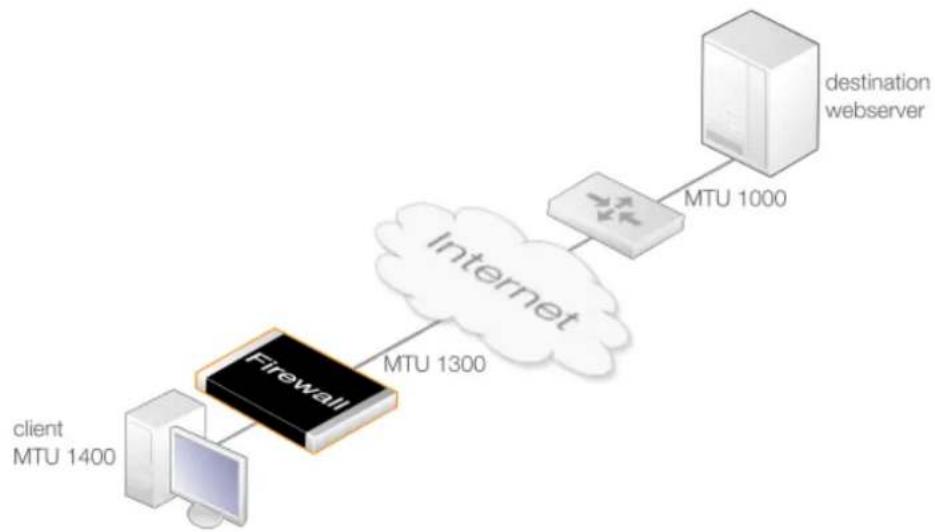
flowchart
graph LR
    A["client MTU 1400"] --> B["Firewall"]
    B --> C["Internet"]
    C --> D["MTU 1300"]
    D --> E["destination webserver"]
    F["MTU 1000"] --> E
Figure 3.1. Path MTU Discovery Processing
Assuming that MTU discovery has been enabled on the relevant IP rule set entry, the following
sequence of events illustrates how MTU discovery functions:
- The client tries to open a connection to the server via the firewall using a packet size of 1400 bytes. The packets sent have the DF (Don't Fragment) flag enabled.
- NetDefendOS looks at the MTU property value for the interface object used for the next hop. This is 1300 so the client's packet MTU is too high and fragmentation cannot be performed.
- NetDefendOS sends an ICMP message to the client to indicate that fragmentation is needed and the acceptable MTU for the next hop is 1300 or less.
- The client now resends the packet with the requested 1300 size and this is forwarded by NetDefendOS towards the server.
- The router in front of the server sends back an ICMP message to NetDefendOS to indicate that the packet size is too big and an MTU size of 1000 or less is acceptable.
- NetDefendOS forwards this ICMP message to the client.
- The client now resends again using a packet size of 1000 which is acceptable to both the firewall and the router so the server is now accessible.
Turning Off the DF Flag
NetDefendOS has a global IP setting called Strip Don't Fragment which can be used to disable the DF (Don't Fragment) flag in a packet. The Strip Don't Fragment settings takes an integer value which is the MTU size below which the DF flag is always disabled. By default, this property has a value of 65535 so the DF flag is always disabled.
Disabling the DF flag means that path MTU discovery will not be used for that packet and it therefore becomes a possibility that a packet above the acceptable MTU size of network equipment will be fragmented. In most cases, this will only cause a degradation in performance.
However, explicitly enabling path MTU discovery on a Service object will override the Strip Don't Fragment setting and so it does not need to be changed for MTU discovery.

Note: Not enabling MTU discovery can cause problems
Disabling path MTU discovery can have unintended side effects. If the forwarding of ICMP errors is disabled, the packet flow can stop if an upstream device sends an ICMP error in order to lower the MTU and this is not forwarded to the originator of the traffic.
One way to deal with this potential problem is to use the global Strip Don't Fragment setting to disable the DF flag so packets that are too long can be fragmented when needed.
Example 3.21. Enabling Path MTU Discovery on an IP Policy
This example shows how to set up path MTU discovery for an IP Policy that already exists called int_to_ext_http. The rule NATs internal clients to the Internet. The clients are surfing the Internet so a Service object called my_http_pmd_service will be created which has path MTU discovery enabled and this will be associated with the IP Policy.
Command-Line Interface
First, create a service object:
gw-world:/> add Service ServiceTCPUDP my_http_pmd_service
Type=TCP
DestinationPorts=80,443
PassICMPReturn=Yes
AllowIPv4PathMTUDiscovery=Yes
Next, modify the IP policy to use the new service.
gw-world:/> set IPPolicy int_to_ext_http Service=my_http_pmd_service
Web Interface
First, create a new service object:
-
Go to: Local Objects > Services > Add > TCP/UDP service
-
Enter the following:
-
Name: my_http_pmd_service
- Type: TCP
• Destination Port: 80,443 - Enable Forward ICMP Errors
- Enable Enable IPv4 Path MTU Discovery
Next, modify the IP policy to use the new service:
- Go to: Policies > Firewalling > Main IP Rules
- Select the IP policy called int_to_ext_http
- Go to: Service
- Select my_http_pmd_service from the Service list
- Click OK
3.4. Interfaces
3.4.1. Overview
An Interface is an important logical building block in NetDefendOS. All network traffic that transits through, originates from or is terminated in the D-Link firewall, does so through one or more interfaces.
Source and Destination Interfaces
An interface can be viewed as a doorway through which network traffic passes to or from NetDefendOS. An interface can have one of the following functions:
• A Source Interface
When traffic arrives through an interface, that interface is referred to in NetDefendOS as the source interface (also sometimes known as the receiving or incoming interface).
• A Destination Interface
When traffic leaves after being checked against NetDefendOS's security policies, the interface used to send the traffic is referred to in NetDefendOS as the destination interface (also sometimes known as the sending interface).
All traffic passing through NetDefendOS has both a source and destination interface. As explained in more depth later, the special logical interface core is used when NetDefendOS itself is the source or destination for traffic.
Interface Types
NetDefendOS supports a number of interface types, which can be divided into the following four major groups:
- Ethernet Interfaces
Each Ethernet interface represents a physical Ethernet interface on a NetDefendOS-based product. All network traffic that originates from or enters a D-Link firewall will pass through one of the physical interfaces.
NetDefendOS currently supports Ethernet as the only physical interface type. For more information about Ethernet interfaces, see Section 3.4.2, "Ethernet Interfaces".
- Sub-interfaces
Some interfaces require a binding to an underlying physical interface in order to transfer data. This group of interfaces is called Physical Sub-Interfaces.
NetDefendOS has support for two types of sub-interfaces:
- Virtual LAN (VLAN) interfaces as specified by IEEE 802.1Q. When routing IP packets over a Virtual LAN interface, they will be encapsulated in VLAN-tagged Ethernet frames. For more information about Virtual LAN interfaces, see Section 3.4.4, "VLAN".
- PPPoE (PPP-over-Ethernet) interfaces for connections to PPPoE servers. More information about this topic can be found in Section 3.4.6, "PPPoE".
- Tunnel Interfaces
Tunnel interfaces are used when network traffic is being tunneled between the system and another tunnel end-point in the network, before it gets routed to its final destination. VPN tunnels are often used to implement virtual private networks (VPNs) which can secure communication between two firewalls.
To accomplish tunneling, additional headers are added to the traffic that is to be tunneled. Furthermore, various transformations can be applied to the network traffic depending on the type of tunnel interface. For example, when routing traffic over an IPsec interface, the payload is usually encrypted to achieve confidentiality.
NetDefendOS supports the following tunnel interface types:
i. IPsec interfaces are used as end-points for IPsec VPN tunnels. More information about this topic can be found in Section 10.3, "IPsec".
ii. PPTP/L2TP interfaces are used as end-points for PPTP or L2TP tunnels. More information about this topic can be found in Section 10.4, "PPTP/L2TP".
iii. GRE interfaces are used to establish GRE tunnels. More information about this topic can be found in Section 3.4.7, "GRE Tunnels".
- Loopback Interfaces
A loopback interface is a special type of interface that will take all packets sent through it and pass them on out through the loopback interface configured as the one to loop to. These are almost exclusively used for Virtual Routing scenarios.
More information about this topic can be found in Section 3.4.9, "Loopback Interfaces".
All Interfaces are Logically Equivalent
Even though the different types of interfaces may be very different in the way they function, NetDefendOS treats all interfaces as logically equivalent. This is an important and powerful concept and means that all types of interfaces can be used interchangeably in the various NetDefendOS rule sets and other configuration objects. This results in a high degree of flexibility in how traffic can be examined, controlled and routed.
Interfaces have Unique Names
Each interface in NetDefendOS is given a unique name to be able to identify and select it for use with other NetDefendOS objects in a configuration. Some interface types, such as physical Ethernet interfaces, are already provided by NetDefendOS with relevant default names that are possible to modify if required. New interfaces defined by the administrator will always require a user-provided name to be specified.

Important: Remove references before removing interfaces
If a logical interface is to be deleted from a NetDefendOS configuration, it is important to first remove any references to that interface. For example, entries in the IP rule set that refer to that interface should be removed or changed.
The any Interface
When specifying the filtering criteria for a rule, such as an IP Policy object, the Interface property can be specified as having the value of any. This means that any logical interface (not just physical interfaces) can match this filtering criteria.
The core Interface
When specifying the filtering criteria for a rule, such as an IP Policy object, the Interface property can also be specified as having the value of core. This indicates that it is NetDefendOS itself that will deal with traffic to and from the interface.
One example of when the core interface must be specified is when the D-Link firewall acts as a PPTP or L2TP server or responds to ICMP "Ping" requests. By specifying the Destination Interface of a route as core, NetDefendOS will know that it is itself that is the traffic's destination and it must be handled in some way (such as responding to an ICMP ping request).
Usually, when the IP address of a physical interface is the Destination Network for traffic, the corresponding Destination Interface will be core. This is because the IP address of all physical interfaces are, by default, core routed. The term core routed means that the NetDefendOS routing tables will specify that an Ethernet interface's automatically created network address book object is already routed to that interface.
A recurrent situation when the core interface is specified is when any type of configuration rule is targeting traffic arriving from the Internet at a public IP address assigned to a physical interface. Assume that the interface connected to the Internet is wan and that the public IPv4 address assigned to that interface is wan_ip. In such a case, the filtering properties of any configuration rule that targets this traffic would be as shown below.
| Source Interface | Source Network | Destination Interface | Destination Network |
| wan all-nets core wan_ip |
The core interface is specified here because the address wan_ip is automatically routed on the core interface by NetDefendOS. Note a Service property value is not specified in the above set of values but this would also be included so as to target a specific protocol, or perhaps allow any protocol.
The above set of filtering properties would often be used with an IP rule set entry if it was allowing ICMP ping requests from the Internet or if SAT translation was being applied to Internet traffic trying to reach a protected server with a private IP address.
Disabling an Interface
Should it be desirable to disable an interface so that no traffic can flow through it, this can be done with the CLI using the command:
gw-world:/> set Interface Ethernet <interface-name> -disable
Where
To re-enable an interface, the command is:
gw-world:/> set Interface Ethernet <interface-name> -enable
Disabling interfaces can also be done through the Web Interface.
3.4.2. Ethernet Interfaces
The IEEE 802.3 Ethernet standard allows various devices to be attached at arbitrary points or
"ports" to a physical transport mechanism such as a coaxial cable. Using the CSMA/CD protocol, each Ethernet connected device "listens" to the network and sends data to another connected device when no other is sending. If 2 devices broadcast simultaneously, algorithms allow them to re-send at different times.

Note: Usage of the terms "interface" and "port"
The terms Ethernet interface and Ethernet port can be used interchangeably. In this document, the term Ethernet interface is used throughout so it is not confused with the port associated with IP communication.
Ethernet Frames
Devices broadcast data as Ethernet frames and other devices "listen" to determine if they are the intended destination for any of these frames. A frame is a sequence of bits which specify the originating device plus the destination device plus the data payload along with error checking bits. A pause between the broadcasting of individual frames allows devices time to process each frame before the next arrives and this pause is progressively smaller with the faster data transmission speeds found in normal Ethernet, then Fast Ethernet and finally Gigabit Ethernet.
Physical Ethernet Interfaces
Each logical NetDefendOS Ethernet interface corresponds to a physical Ethernet interface in the system. The number of interfaces, their link speed and the way the interfaces are realized, is dependent on the D-Link hardware model.

Note: Interface sockets connected via a switch fabric
Some hardware platforms for NetDefendOS use an integrated layer 2 switch for providing additional physical Ethernet interface sockets. Externally there can be several separate sockets but these are joined via an internal switch fabric.
Such joined interfaces are seen as a single interface by NetDefendOS and the NetDefendOS configuration uses a single logical interface name to refer to all of them. The specifications for different hardware models will indicate where this is the case.
Ethernet Properties
An Ethernet object in a NetDefendOS configuration corresponds to a physical Ethernet interface. The following are the key properties that can be set for this type of object:
- Interface Name
The names of the Ethernet interfaces are predefined by the system, and are mapped to the names of the physical interfaces.
The names of the Ethernet interfaces can be changed to better reflect their usage. For example, if an interface named dmz is connected to a wireless LAN, it might be convenient to change the interface name to radio. For maintenance and troubleshooting, it is recommended to tag the corresponding physical interface with the new name.

Note: Interface enumeration
The startup process will enumerate all available Ethernet interfaces. Each interface will be given a name of the form lanN, wanN and dmz, where N represents the number of the interface if the firewall has more than one of these interfaces. In most of the examples in this guide, lan is used for LAN traffic and wan is used for WAN traffic. If the firewall does not have these interface names, please substitute the references with the actual names of the interfaces.
• IP Address
Each Ethernet interface is required to have an Interface IP Address, which can be either a static address or an address provided by DHCP. The interface IP address is used as the primary address for communicating with the system through the specific Ethernet interface.
NetDefendOS IP4 Address objects are usually used to define the IPv4 addresses of Ethernet interfaces. Those objects are normally auto-generated by the system. For more information, please see Section 3.1.5, "Auto-Generated Address Objects".

Tip: Specifying multiple IP addresses on an interface
Multiple IP addresses can be specified for an Ethernet interface by using the ARP Publish feature. (For more information, see Section 3.5, "ARP").
• Network
In addition to the interface IP address, a Network address is also specified for an Ethernet interface. The Network address provides information to NetDefendOS about what IP addresses are directly reachable through the interface. In other words, those residing on the same LAN segment as the interface itself. In the routing table associated with the interface, NetDefendOS will automatically create a direct route to the specified network over the actual interface.
- Default Gateway
A Default Gateway address can optionally be specified for an Ethernet interface. This is normally the address of a router and very often the router which acts as the gateway to the Internet.
When a default gateway is specified then, by default, a route to the network all-nets is automatically created in the NetDefendOS routing table for the interface. This means that any traffic which does not have a more specific matching route will be sent via that interface to the default gateway. This behavior can be changed by disabling an interface's advanced option for creating the default route automatically.
Normally, only one default all-nets route to the default gateway needs to exist in the routing table.

Note: The all-nets IP address object
The all-nets IP object (IP address: 0.0.0.0/0) includes the multicast IP address range (224.0.0.0 => 239.255.255.255). For more information about this topic, see
Section 4.8, "Multicast Routing".
- Receive Multicast Traffic
This option controls the reception of multicast IP packets on that interface. There are three options:
i. Off - Promiscuous mode is switched off so that multicast packets are silently dropped.
Promiscuous mode will still be automatically switched on with OSPF or high availability.
ii. On - Multicast traffic can always be received by the interface. Promiscuous mode is always the receive mode of the interface.
iii. Auto - If an IP rule set entry exists which applies to a multicast packet's destination IP address, then the Ethernet interface automatically gets its receive mode set to promiscuous in order to receive multicast packets. This is the default.
This setting does not affect the automatic usage of promiscuous mode with OSPF or high availability. For a further discussion of promiscuous mode, see the description below.
- Enable DHCP Client
NetDefendOS includes a DHCP client feature for dynamic assignment of address information by a connected DHCP server. This feature is often used for receiving external IPv4 address information from an ISP's DHCP server for Internet connection.
The information that can be set using DHCP includes the IPv4 address as well as the broadcast address of the interface, the local network that the interface is attached to, and the default gateway.
All addresses received from the DHCP server are assigned to corresponding IP4Address objects. In this way, dynamically assigned addresses can be used throughout the configuration in the same way as static addresses. By default, the objects in use are the same ones as defined in Section 3.1.5, "Auto-Generated Address Objects".
By default, DHCP is disabled on Ethernet interfaces. If the interface is being used for connection to the Internet via an ISP using fixed IP addresses then DHCP shouldn't be used. In addition, DHCPv6 for IPv6 addresses is available as a separate property of the interface configuration object and this is also disabled by default (see Section 5.6.1, "DHCPv6 Client").

Important: DHCP clients are not supported in HA clusters
Both IPv4 DHCP clients and DHCPv6 clients are not supported in a high availability cluster. If either property is enabled for an interface then this will produce the error Shared HA IP address not set when trying to commit the configuration.
DNS server addresses received through DHCP on an interface which is named

Note: A gateway IP cannot be deleted with DHCP enabled
If DHCP is enabled for a given Ethernet interface then any gateway IP address (for example, the address of an ISP) that is defined for that interface cannot be deleted.
To remove the gateway address, the DHCP option must be first disabled.
If DHCP is enabled then there is a set of interface specific advanced settings:
i. A preferred IP address can be requested.
ii. A preferred lease time can be requested.
iii. Static routes can be sent from the DHCP server.
iv. Do not allow IP address collisions with static routes.
v. Do not allow network collisions with static routes.
vi. Specify an allowed IP address for the DHCP lease.
vii. Specify an address range for DHCP servers from which leases will be accepted.
- DHCP Hostname
In some, infrequent cases a DHCP server may require a hostname to be sent by the DHCP client.
- Enable Transparent Mode
The recommended way to enable Transparent Mode is to add switch routes, as described in Section 4.9, "Transparent Mode". An alternative method is to enable transparent mode directly on an interface with this option.
When enabled, default switch routes are automatically added to the routing table for the interface and any corresponding non-switch routes are automatically removed.
- Hardware Settings
In some circumstances it may be necessary to change hardware settings for an interface. The available options are:
i. The speed of the link can be set. Usually this is best left as Auto.
ii. The MAC address can be set if it needs to be different to the MAC address built into the hardware. Some ISP connections might require this.
- Virtual Routing
To implement virtual routing where the routes related to different interfaces are kept in separate routing table, there are a number of options:
i. Make the interface a member of all routing tables. This option is enabled by default and means that traffic arriving on the interface will be routed according to the main routing table. Routes for the interface IP will be inserted into all routing tables.
ii. The alternative to the above is to insert the route for this interface into only a specific routing table. The specified routing table will be used for all route lookups unless overridden by a routing rule.
• Automatic Route Creation
Routes can be automatically added for the interface. This addition can be of the following types:
i. Add a route for this interface for the given network. This is enabled by default.
ii. Add a default route for this interface using the given default gateway. This is enabled by default.
• MTU
This determines the maximum size of packets in bytes that can be sent on this interface. By default, the interface uses the maximum size supported.
• High Availability
There are two options which are specific to high availability clusters:
i. A private IPv4 address can be specified for this interface.
ii. An additional option is to disable the sending of HA cluster heartbeats from this interface.
• Quality Of Service
The option exists to copy the IP DSCP precedence to the VLAN priority field for any VLAN packets. This is disabled by default.
Promiscuous Mode
In most situations, an interface will run in normal, non-promiscuous mode. This means that when an arriving packet has a destination MAC address which does not match the MAC address of the receiving interface, the packet is discarded by the interface without being passed on to NetDefendOS for processing. However, this behavior is incorrect with the following NetDefendOS features:
- Multicast
• High Availability
• OSPF
For these features, the packet needs to be passed to NetDefendOS even though there is a mismatch of MAC addresses. To do this, promiscuous mode must be enabled on the interface but the administrator does not need to do this manually. NetDefendOS will automatically switch an interface to promiscuous mode when required. With multicast only, the automatic usage of promiscuous mode can be controlled using the Ethernet object property Receive Multicast Traffic which has a default value of Auto so the correct mode is selected by NetDefendOS.
The current mode of an Ethernet interface can be viewed by using the ifstat
gw-world:/> ifstat If1
Iface If1
    Builtin e1000 - Gigabit Ethernet Bus 0 Slot 4 Port 0 IRQ 0
    Media : "Autonegotiated"
    Link Status : 100 Mbps Full Duplex
    Receive Mode : Promiscuous
Changing the IP address of an Ethernet Interface
To change the IP address on an interface, we can use one of two methods:
- Change the IP address directly on the interface. For example, if we want to change the IPv4 address of the Ian interface to 10.1.1.2, we could use the CLI command:
gw-world:/> set Interface Ethernet lan IP=10.1.1.2
As explained next, this way of changing the IPv4 address is not recommended.
- Instead, the lan_ip object in the NetDefendOS Address Book should be assigned the new address since it is this object that is used by many other NetDefendOS objects, such as IP rule set entries. The CLI command to do this would be:
gw-world:/> set Address IP4Address InterfaceAddresses/lan_ip Address=10.1.1.2
This same operation could also be done through the Web Interface.
A summary of CLI commands that can be used with Ethernet interfaces can be found in Section 3.4.2.1, "Useful CLI Commands for Ethernet Interfaces".
The Difference Between Logical and Physical Ethernet Interfaces
The difference between logical and physical interfaces can sometimes be confusing. The logical Ethernet interfaces are those which are referred to in a NetDefendOS configuration. When using the Web Interface, only the logical interfaces are visible and can be managed.
When using the CLI, both the logical and physical interfaces can be managed. For example, to change the name of the logical interface If1 to be Ian, the CLI command is:
gw-world:/> set Interface Ethernet If1 Name=lan
This changes the logical name of the interface (and all references to it) but does not change the underlying physical name. For example, the CLI command ifstat shows the names of only the physical interfaces and this list is unaffected by the above name change.
In the CLI, a physical interface is represented by the object EthernetInterface. To display all the characteristics of an interface, for example for interface If1, the CLI command is:
gw-world:/> show EthernetDevice If1
The output from this command shows details about the physical Ethernet card including the bus, slot and port number of the card as well as the Ethernet driver being used. These details are not relevant to the logical interface object associated with the physical interface.
3.4.2.1. Useful CLI Commands for Ethernet Interfaces
This section summarizes the CLI commands most commonly used for examining and manipulating NetDefendOS Ethernet interfaces.
Ethernet interfaces can also be examined through the Web Interface but for some operations the CLI must be used.
Showing Assigned Interfaces
To show the current interface assigned to the IP address wan_ip:
gw-world:/> show Address IP4Address InterfaceAddresses/wan_ip
Property Value
Name: wan_ip
Address: 0.0.0.0
UserAuthGroups: <empty>
NoDefinedCredentials: No
Comments: IP address of interface wan
To show the current interface assigned to the network wan_net:
gw-world:/> show Address IP4Address InterfaceAddresses/wan_net
Property Value
Name: wan_net
Address: 0.0.0.0/0
UserAuthGroups: <empty>
NoDefinedCredentials: No
Comments: Network on interface wan
To show the current interface assigned to the gateway wan_gw:
gw-world:/> show Address IP4Address InterfaceAddresses/wan_gw
Property Value
Name: wan_gw
Address: 0.0.0.0
UserAuthGroups: <empty>
NoDefinedCredentials: No
Comments: Default gateway for interface wan
By using the tab key at the end of a line, tab completion can be used to complete the command:
gw-world:/> show Address IP4Address InterfaceAddresses/wan_<tab>
[<Category>] [<Type> [<Identifier>]]:
InterfaceAddresses/wan_br InterfaceAddresses/wan_gw
InterfaceAddresses/wan_dns1 InterfaceAddresses/wan_ip
InterfaceAddresses/wan_dns2 InterfaceAddresses/wan_net
Here, tab completion is used again at the end of the command line:
gw-world;/> set Address IP4Address<tab>
[<Category>] <Type> [<Identifier>];
dnsserver1_ip InterfaceAddresses/wan_br timesyncsrv1_ip InterfaceAddresses/aux_ip InterfaceAddresses/wan_dns1 InterfaceAddresses/aux_net InterfaceAddresses/wan_dns2 InterfaceAddresses/dmz_ip InterfaceAddresses/wan_gw InterfaceAddresses/dmz_net InterfaceAddresses/wan_ip InterfaceAddresses/lan_ip InterfaceAddresses/wan_net InterfaceAddresses/lan_net Server
Setting Interface Addresses
The CLI can be used to set the address of the interface:
gw-world:/> set Address IP4Address InterfaceAddresses/wan_ip
Address=172.16.5.1
Modified IP4Address InterfaceAddresses/wan_ip.
Enabling DHCP
The CLI can be used to enable DHCP on the interface:
gw-world:/> set Interface Ethernet wan DHCPEnabled=yes
Modified Ethernet wan.
Ethernet Device Commands
Some interface settings provide direct management of the Ethernet settings themselves. These are particularly useful if D-Link hardware has been replaced and Ethernet card settings are to be changed, or if configuring the interfaces when running NetDefendOS on non-D-Link hardware.
For example, to display all Ethernet interface information use the command:
gw-world:/> show EthernetDevice
This command lists all Ethernet interfaces. Those defined as logical interfaces in the current configuration are marked by a plus "+" symbol on the left of the listing.
Those interfaces that physically exist but are not part of the configuration are indicated with a minus "-" symbol at the left. These will be deleted after the configuration is activated. If a deleted interface in the interface list is to be restored, this can be done with the undelete command:
gw-world:/> undelete EthernetDevice <interface>
Individual interface details can be displayed, for example for the interface If1, with the command:
gw-world:/> show EthernetDevice If1
Property Value
Name: If1
EthernetDriver: E1000EthernetPCIDriver
PCIBus: 0
PCISlot: 17
PCIPort: 0
"
The set command can be used to control an Ethernet interface. For example, to disable an interface lan, the following command can be used:
gw-world:/> set EthernetDevice lan -disable
To enable the interface lan:
gw-world:/> set EthernetDevice lan -enable
To set the driver on an Ethernet interface card the command is:
gw-world:/> set EthernetDevice lan EthernetDriver=<driver> PCIBus=<X> PCISlot=<Y> PCIPort=<Z>
For example, if the driver name is IXP4NPEEthernetDriver for the bus, slot, port combination 0, 0, 2 on the wan interface, the set command would be:
gw-world:/> set EthernetDevice lan
EthernetDriver=IXP4NPEEthernetDriver
PCIBus=0
PCISlot=0
PCIPort=2
This command is useful when a restored configuration contains interface names that do not match the interface names of new hardware. By assigning the values for bus, slot, port and driver of a physical interface to a logical interface in the configuration, the logical interface is mapped to the physical interface. However, this mapping must be done before the configuration is activated.
For a complete list of all CLI options see the CLI Reference Guide.
3.4.2.2. Advanced Ethernet Interface Settings
This section details the advanced settings available for NetDefendOS Ethernet interfaces. The settings are global and affect all physical interfaces.
DHCP Settings
Below, is a list of the advanced DHCP settings for NetDefendOS Ethernet interfaces.
DHCP\_AllowGlobalBcast
Allow DHCP server to assign 255.255.255.255 as broadcast. (Non-standard.)
Default: Disabled
DHCP\_DisableArpOnOffer
Disable the ARP check done by NetDefendOS on the offered IP. The check issues an ARP request to see if the IP address is already in use.
Default: Disabled
DHCP\_UseLinkLocalIP
If this is enabled NetDefendOS will use a Link Local IP (169.254.*.*) instead of 0.0.0.0 while waiting for a lease.
Default: Disabled
DHCP\_ValidateBcast
Require that the assigned broadcast address is the highest address in the assigned network.
Default: Enabled
DHCP\_MinimumLeaseTime
Minimum lease time (seconds) accepted from the DHCP server.
Default: 60
Hardware Settings
Below, is a list of the advanced hardware settings that are available for NetDefendOS Ethernet interfaces. These settings are only relevant to NetDefendOS running on non-D-Link hardware.
Ringsize\_e1000\_rx
Size of the rx buffer on e1000 cards.
Default: 64
Ringsize\_e1000\_tx
Size of the tx buffer on e1000 cards.
Default: 256
Ringsize\_e100\_rx
Size of the rx buffer on e100 cards.
Default: 32
Ringsize\_e100\_tx
Size of the tx buffer on e100 cards.
Default: 128
Ringsize\_yukon\_rx
Size of Yukon receive ring (per interface).
Default: 256
Ringsize\_yukon\_tx
Size of Yukon send ring (per interface).
Default: 256
Ringsize\_yukonii\_rx
Size of Yukon-II receive ring (per interface).
Default: 256
Ringsize\_yukonii\_tx
Size of Yukon-II send ring (per interface).
Default: 256
Interface Monitor Settings
Below, is a list of the monitor settings that are available for NetDefendOS Ethernet interfaces.
IfaceMon\_e1000
Enable interface monitor for e1000 interfaces.
Default: Enabled
IfaceMon\_BelowCPULoad
Temporarily disable ifacemon if CPU load goes above this percentage.
Default: 80
IfaceMon\_BelowIfaceLoad
Temporarily disable ifacemon on and interface if network load on the interface goes above this percentage.
Default: 70
IfaceMon\_ErrorTime
How long a problem must persist before an interface is reset.
Default: 10
IfaceMon\_MinInterval
Minimum interval between two resets of the same interface.
Default: 30
IfaceMon\_RxErrorPerc
Percentage of errors in received packets at which to declare a problem.
Default: 20
IfaceMon\_TxErrorPerc
Percentage of errors in sent packets at which to declare a problem.
Default: 7
3.4.3. Link Aggregation
Introduction
Where individual physical Ethernet interfaces of a D-Link firewall cannot provide the bandwidth required for a specific stream of traffic, it is possible to use the NetDefendOS Link Aggregation feature to combine two or more physical interfaces together so they act as one logical NetDefendOS interface. This feature is sometimes referred to by other security product vendors
using names such as Link Bundling or NIC Teaming.
In NetDefendOS, aggregated Ethernet interfaces are represented by a Link Aggregation configuration object. It should be noted that this interface type is an L2 interface, just like a single Ethernet interface.
An Example Use Case
An example use case is where a D-Link firewall might only have multiple one Gigabit Ethernet interfaces but the requirement for a particular traffic flow is bandwidth of three Gigabits. A logical Link Aggregation object could then be created which combines the capacities of three physical interfaces. This object can then be used in the NetDefendOS configuration like any other interface and can be part of the Route and the IPRule or IPPolicy objects that govern the traffic flow. NetDefendOS will then automatically spread the traffic between the physical interfaces.
The diagram below shows a typical scenario where three 1Gb networks need to communicate with a 10Gb network backbone through a firewall which only has 1 Gb interfaces. Three of the firewall's 1Gb interfaces are connected to an external switch and grouped into a Link Aggregation configuration object. The switch then provides the 10Gb link to the backbone.
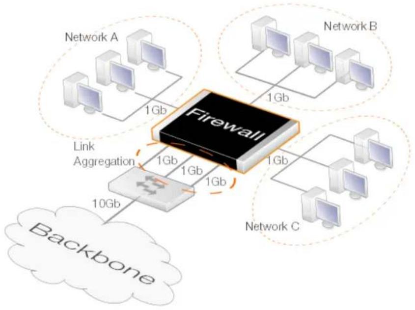
flowchart
graph TD
    Firewall["Firewall"] -->|1Gb| NetworkA["Network A"]
    Firewall -->|1Gb| NetworkB["Network B"]
    Firewall -->|1Gb| NetworkC["Network C"]
    Firewall -->|1Gb| LinkAggregation["Link Aggregation"]
    LinkAggregation -->|1Gb| Firewall
    Firewall -->|1Gb| Backbone["Backbone"]
    style Firewall fill:#f9f,stroke:#333
    style NetworkA fill:#ccf,stroke:#333
    style NetworkB fill:#ccf,stroke:#333
    style NetworkC fill:#ccf,stroke:#333
    style LinkAggregation fill:#cfc,stroke:#333
    style Backbone fill:#fcc,stroke:#333
Figure 3.2. Link Aggregation

Note: Switch fabric connected interfaces cannot be used
Where a single logical interface consists of a number of physical interfaces connected through a switch fabric on a D-Link hardware model, that logical interface cannot be part of a link aggregation object.
This is the case for the logical Ian interface on the NetDefend DFL-260E and DFL-860E product models.
Physical Interface Requirements
The following are the requirements for the physical Ethernet interfaces associated with a LinkAggregation configuration object in NetDefendOS:
- A maximum of 16 physical interfaces can be aggregated using one LinkAggregation configuration object.
- All the physical interfaces must operate at the same link speed.
- All the physical interfaces must be connected to the same external switch
Configuring the Mode
The LinkAggregation object's Mode property and as the external switch are configured in either of the following modes:
• Static
When the aggregation is static, NetDefendOS cannot know if one of the interfaces in the aggregation is not working and will try to send the traffic anyway. There is no negotiation taking place between NetDefendOS and the switch to which the aggregated interfaces are connected.
This means that on link failure, a connection can be dropped entirely.
• LACP (Negotiated)
With negotiated aggregation, the switch to which the aggregated interfaces are connected is configured to use LACP (Link Aggregation Control Protocol). This means that should a physical link become inoperative, NetDefendOS will only try to send traffic over the remaining operating links.
The advantage over the Static setting is that NetDefendOS will try to send a limited number of packets over the failed connection before it switches to an alternate, working link. This means that the connection will not be dropped and the connection's external endpoint will experience only minor packet loss.
Individual Interface References Are Ignored
When an EthernetInterface object becomes part of a LinkAggregation object, it can no longer be used as a separate object. If a configuration retains this individual interface usage after aggregation then any references to it in the NetDefendOS configuration will be ignored during operation although the underlying configuration is not changed.
For example, the following will be true:
- Any IP rule set entries that refer to an aggregated interface will be ignored in rule set searches.
- Any routes that refer to an aggregated interface will be ignored in route searches. The ignored routes will still appear in output from the CLI command show routes but will not appear in the CLI command routes.
- If DHCP client functionality is required it should be enabled on the Link Aggregation object and not the individual interfaces in the aggregation.
If DHCP is enabled on any of the individual interfaces, this will be automatically disabled when it is part of a link aggregated group (and automatically re-enabled if the interface leaves the group).
Removing Individual Routing References is Recommended
Whenever configuration changes are committed, NetDefendOS will issue warnings about any aggregated interface references that will be ignored. For example, such a warning is shown below for the interface If1 because it is being used in a Route object.
If1 is not a valid routing interface because it's a Link Aggregation member
For configuration clarity, it is recommended that the administrator removes such redundant interface usage from the NetDefendOS configuration.
Individual Interface Addresses Becomes 0.0.0.0
When an EthernetInterface object becomes part of a LinkAggregation object, its individual IPv4 address becomes 0.0.0.0. This will be seen in the output from the CLI command ifstat.
However, the underlying NetDefendOS configuration is not changed. For example, the associated address book objects are not changed so that if an interface is no longer part of a LinkAggregation object, its IP address will revert back to its original address.
Distribution Methods
The administrator must make a judgment about the traffic being spread across the aggregated physical interfaces and choose one of the following criteria for the distribution:
- DestinationMAC
- SourceIP
- DestinationIP
- SourcePort
- DestinationPort
• IP and Ports (the default)
Choosing the Distribution Method
The algorithm that spreads the traffic between the aggregated interfaces uses hashing with the chosen distribution method as the input. The best distribution method is therefore the one which varies the most. For example, if the source of traffic is a number of internal clients being NATed to the Internet via an ISP, the best choice for the distribution method is most likely SourcePort since this will be chosen randomly as each connection is opened by a client.
An alternative in the above scenario could be SourceIP but only if there is a sufficiently large number of clients. With just a few clients, SourceIP might end up with only one of the aggregated interfaces being used.
If aggregation is being done for a protected web server receiving external requests from remote clients over the Internet, the DestinationIP would not be suitable since all connections would have the server's address. Instead, the more variable SourceIP would be a better choice for the distribution method.
The hashing process to choose the physical Ethernet interface to use takes place each time a new connection is opened. This means that all packets for a given connection will be sent on the same physical interface. The chosen interface for the connection would then only subsequently change if the chosen mode was dynamic and the connection fails.
The Default IP and Ports Distribution Method
The default distribution method is IP and Ports and this takes into account both the source and destination IP address as well as the source and destination port number. It is designed to be a general catch-all solution where the traffic type is known to be variable or where the administrator is uncertain which of the more specific distribution is suitable.
Physical Switch Connections
The physical cable links between the firewall and the external switch can be made either before or after creating the LinkAggregation object and activating the changed configuration.
NetDefendOS will try to send data on the aggregated interfaces as soon as the configuration changes become active.
However, it is recommended that the physical cabling is in place before the LinkAggregation object is activated and saved. This will provide the behavior which is expected from the feature and is particularly relevant if negotiated aggregation (LACP) is used.
Setup with High Availability
When using link aggregation with HA, the connections from the Ethernet ports on each firewall in the HA cluster can connect to the same or different switches. However, if using the same switch, the switch must be configured so that the connections from each firewall are kept separate by creating two link aggregation groups in the switch.
Setting the MTU Value
It is possible to set a specific MTU property value on a link aggregation interface. However, this value will not be used on one of the aggregated Ethernet interfaces if the individual Ethernet interface MTU property is set to a value that is lower than the link aggregation MTU. This is true regardless if the mode is static or negotiated (LACP).
Example 3.22. Link Aggregation
In this example, the Ethernet interfaces If1 and If2 will become part of a single LinkAggregation object called la_if1_if2. It is assumed that this new object will have the predefined IPv4 address object la_if1_if2_ip assigned to it and this address belongs to the network la_if1_if2_net.
The switch the link is connecting is capable of a link negotiation.
Command-Line Interface
gw-world:/> add Interface LinkAggregation la_if1_if2
    Mode=LACP
    IP=la_if1_if2_ip
    Network=la_if1_if2_net
    DistributionAlgorithm=DestinationIP
Web Interface
-
Go to: Network > Interfaces and VPN > Link Aggregation > Add > Link Aggregation
-
Enter the following:
- Name: la_if1_if2
- Distribution Algorithm: DestinationIP
-
Mode: LACP
• IP address (IPv4): la_if1_if2_ip
• Network (IPv4): la_if1_if2_net -
Select If1 from Members and press Include
-
Repeat the previous step to add the If2 interface
-
Click OK
3.4.4.VLAN
Overview
Virtual LAN (VLAN) support in NetDefendOS allows the definition of one or more Virtual LAN interfaces which are associated with a particular physical interface. These are then considered to be logical interfaces by NetDefendOS and can be treated like any other interfaces in NetDefendOS rule sets and routing tables.
VLANs are useful in several different scenarios. A typical application is to allow one Ethernet interface to appear as many separate interfaces. This means that the number of physical Ethernet interfaces on a D-Link firewall need not limit how many totally separated external networks can be connected.
Another typical usage of VLANs is to group together clients in an organization so that the traffic belonging to different groups is kept completely separate in different VLANs. Traffic can then only flow between the different VLANs under the control of NetDefendOS and is filtered using the security policies described by the NetDefendOS rule sets.
As explained in more detail below, VLAN configuration with NetDefendOS involves a combination of VLAN trunks from the firewall to switches and these switches are configured with port based VLANs on their interfaces. Any physical firewall interface can, at the same time, carry both non-VLAN traffic as well VLAN trunk traffic for one or multiple VLANs.
VLAN Processing
NetDefendOS follows the IEEE 802.1Q specification. The specifies how VLAN functions by adding a Virtual LAN Identifier (VLAN ID) to Ethernet frame headers which are part of a VLAN's traffic.
The VLAN ID is a number between 0 and 4095 which is used to identify the specific Virtual LAN to which each frame belongs. With this mechanism, Ethernet frames can belong to different Virtual LANs but can still share the same physical Ethernet link.
The following principles are followed when NetDefendOS processes VLAN tagged Ethernet frames at a physical interface:
- Ethernet frames received on a physical interface by NetDefendOS, are examined for a VLAN ID. If a VLAN ID is found and a matching VLAN interface has been defined for that interface, NetDefendOS will use the VLAN interface as the logical source interface for further rule set processing.
• If there is no VLAN ID attached to an Ethernet frame received on an interface then the source
of the frame is considered to be the physical interface and not a VLAN.
- If VLAN tagged traffic is received on a physical interface and there is no VLAN defined for that interface in the NetDefendOS configuration with a corresponding VLAN ID then that traffic is dropped by NetDefendOS and an unknown_vlanid log message is generated.
- The VLAN ID must be unique for a single NetDefendOS physical interface but the same VLAN ID can be used on more than one physical interface. In other words, the same VLAN can span many physical interfaces.
- A physical interface does not need to be dedicated to VLANs and can carry a mixture of VLAN and non-VLAN traffic.
Physical VLAN Connection with VLAN
The illustration below shows the connections for a typical NetDefendOS VLAN scenario.
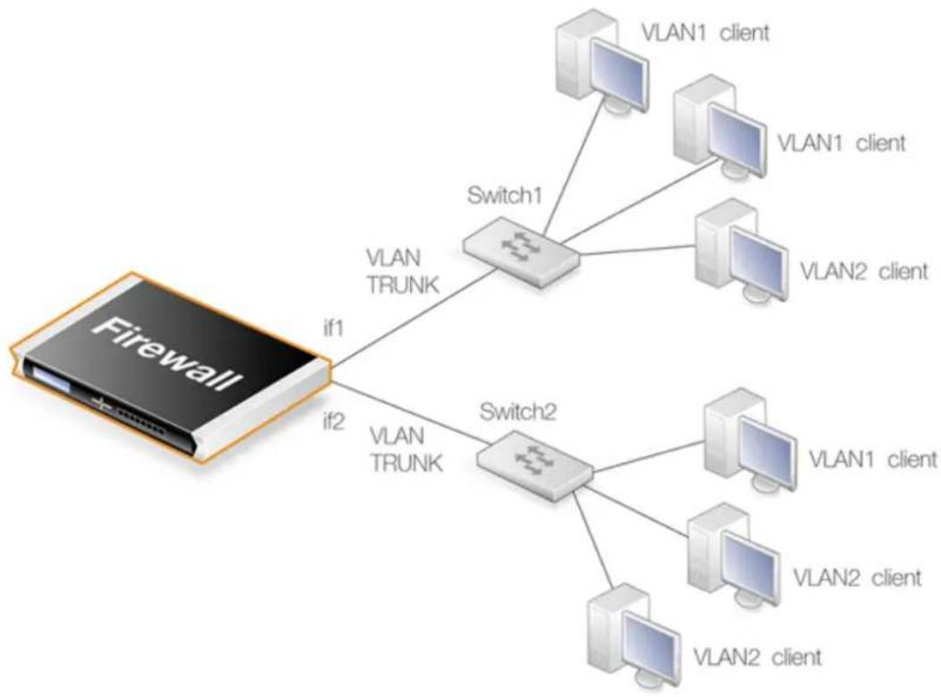
flowchart
graph TD
    A["Firewall"] -->|if1| B["Switch1"]
    A -->|if2| C["Switch2"]
    B --> D["VLAN1 client"]
    B --> E["VLAN2 client"]
    C --> F["VLAN1 client"]
    C --> G["VLAN2 client"]
    B --> H["VLAN TRUNK"]
    C --> I["VLAN TRUNK"]
Figure 3.3. VLAN Connections
With NetDefendOS VLANs, the physical connections are as follows:
- One or more VLANs are configured on a physical firewall interface and this is connected directly to a switch. This link acts as a VLAN trunk. The switch used must support port based VLANs. This means that each port on the switch can be configured with the ID of the VLAN or VLANs that a port is connected to. The port on the switch that connects to the firewall should be configured to accept the VLAN IDs that will flow through the trunk.
In the illustration above the connections between the interfaces if1 and if2 to the switches Switch1 and Switch2 are VLAN trunks.
- Other ports on the switch that connect to VLAN clients are configured with individual VLAN IDs. Any device connected to one of these ports will then automatically become part of the VLAN configured for that port. In Cisco switches this is called configuring a Static-access VLAN.
On Switch1 in the illustration above, one interface is configured to be dedicated to VLAN2 and two others are dedicated to VLAN1.
The switch could also forward trunk traffic from the firewall into another trunk if required.
- More than one interface on the firewall can carry VLAN trunk traffic and these will connect to separate switches. More than one trunk can be configured to carry traffic with the same VLAN ID.
Limitations on the Total Number of VLANs Allowed
The number of VLAN interfaces that can be defined for a NetDefendOS installation is limited by the type of NetDefendOS license. Different hardware models have different licenses and different limits on VLANs.
Summary of VLAN Setup
Below are the key steps for setting up a VLAN interface.
- Assign a name to the VLAN interface.
- Select the physical interface for the VLAN.
- Assign a VLAN ID that is unique on the physical interface.
- Optionally specify an IP address for the VLAN.
- Optionally specify an IP broadcast address for the VLAN.
- Create the required route(s) for the VLAN in the appropriate routing table.
- Create rules in the IP rule set to allow traffic through on the VLAN interface.

Note: Port Based VLAN
VLANs on the LAN interfaces of the NetDefend DFL-260E and DFL-860E models are configured differently from standard NetDefendOS VLANs. The setup is described fully in Appendix E, DFL-260E/860E Port Based VLAN.
The VLAN processing overhead for these LAN interfaces is performed by the switch fabric that connects these interfaces and not by NetDefendOS. This allows the interfaces to be divided up into a number of different VLANs. This feature is referred to as Port Based VLAN.
It is important to understand that the administrator should treat a VLAN interface just like a physical interface in that they require both appropriate IP rule set and routing table entries to exist in the NetDefendOS configuration for traffic to flow through them. For example, if no IP rule set entry with a particular VLAN interface as the source interface is defined allowing traffic to flow then packets arriving on that interface will be dropped.
VLAN advanced settings
There is a single advanced setting for VLAN:
Unknown VLAN Tags
What to do with VLAN packets tagged with an unknown ID.
Default: DropLog
Example 3.23. Defining a VLAN
This simple example defines a virtual LAN called VLAN10 with a VLAN ID of 10. The IP address of the VLAN is assumed to be already defined in the address book as the object vlan10_ip.
Command-Line Interface
gw-world:/> add Interface VLAN VLAN10
Ethernet=lan
IP=vlan10_ip
Network=all-nets
VLANID=10
Web Interface
-
Go to: Network > Interfaces and VPN > VLAN > Add > VLAN
-
Now enter:
• Name: Enter a name, for example VLAN10
- Interface: Ian
• VLAN ID: 10
- IP Address: vlan10_ip
• Network: all-nets
- Click OK
3.4.5. Service VLAN
In certain scenarios, it is desirable to wrap traffic from multiple VLANs inside a single parent VLAN. This is sometimes referred to as a Q-in-Q VLAN or a Stacked VLAN. In NetDefendOS, it is called a Service VLAN and follows the standard defined by IEEE 802.1ad. It can be said that a service LAN tunnels other VLANs and provides a convenient method of using a single logical connection on a single Ethernet interface through which multiple VLANs can flow.
A Service VLAN Use Case
A D-Link firewall can act as a terminator for a service VLAN. A typical use case for service VLAN termination is illustrated in the diagram below.
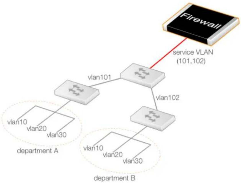
flowchart
graph TD
    Firewall["Firewall"] -->|service VLAN (101,102)| Server1["Server 101"]
    Server1 -->|vlan101| A["Department A"]
    Server1 -->|vlan102| B["Department B"]
    Server1 -->|vlan103| B
    A -->|vlan20 vlan30| A
    B -->|vlan20 vlan30| B
Figure 3.4. A Service VLAN Use Case
Here, corporate departments A and B each use two VLANs where the VLAN IDs 10 and 20 can be duplicated. A switch in each department connects it to another central corporate switch using the unique VLAN IDs 101 and 102. This central switch can now connect to the D-Link firewall using a single service LAN which tunnels the 101 and 102 VLANs.
Defining a Service VLAN
The standard NetDefendOS VLAN object is used to define a service VLAN but the Type property for the object is set to 0x88a8. This Type property corresponds to the TPID setting in the VLAN tag and this is explained further below.
After the service VLAN object is defined, a non-service VLAN object can be placed inside it by setting its Base Interface property to be the service VLAN object. This is demonstrated in the example below.
Example 3.24. Defining a Service VLAN
This example defines a service VLAN called svlan_A with a ID of 100 on the physical interface If3.
Command-Line Interface
gw-world:/> add Interface VLAN svlan_A
Type=0x88a8
BaseInterface=If3
VLANID=100
IP=svlan_A_ip
Network=svlan_A_net
A VLAN object can now be added to this:
gw-world:/> add Interface VLAN vlan1
BaseInterface=svlan_A
VLANID=1
IP=vlan1_ip
Network=vlan1_net
Web Interface
-
Go to: Network > Interfaces and VPN > VLAN > Add > VLAN
-
Now enter:
- Name: svlan_A
- Type: 0x88a8
- Base Interface: If3
• VLANID: 100
- IP Address: svlan_A_ip
• Network: svlan_A_net
- Click OK
A VLAN object can now be added to this:
-
Go to: Network > Interfaces and VPN > VLAN > Add > VLAN
-
Now enter:
- Name: vlan1
- Base Interface: svlan_A
• VLANID: 1
- IP Address: vlan1_ip
- Network: vlan1_net
- Click OK

Important: Enable jumbo frame support in the network
For optimum performance, it is recommended to enable jumbo frame support in the external network equipment which handles service VLAN traffic. This is because service VLAN traffic will use an Ethernet MTU value that exceeds the standard size of 1500 bytes.
The Complete List of Type Values
The complete list of values that can be used for the Type property in a VLAN object is shown below.
| TPID (Hexadecimal) Decimal Equivalent Description | ||
| 0x8100 | 33024 | IEEE 802.1Q VLAN (the default) |
| 0x88a8 34984 IEEE diffserv Service VLAN | ||
| 0x9100 37120 0x9100 VLAN | ||
| 0x9200 37376 0x9200 VLAN | ||
| 0x9300 37632 0x9300 VLAN | ||
The Type property specifies the Tag Protocol Identifier (TPID) in the VLAN tag.
Since the VLAN object defaults to a Type of 0x8100 (a standard VLAN), the only Type usually needed is 0x88a8 to specify a service VLAN. The last three entries in the list may be needed to provide interoperability with external equipment from some manufacturers.
Service VLANs within Service VLANs
The BaselInterface property of a service VLAN object can be another service VLAN object. In other words, one service VLAN can contain another service VLAN.
Although unusual beyond a couple of levels, NetDefendOS permits up to 16 levels of nesting, with a VLAN object at the first level wrapped by a maximum of 15 levels of nested service VLAN objects.
3.4.6. PPPoE
Point-to-Point Protocol over Ethernet (PPPoE) is a tunneling protocol used for connecting multiple users on an Ethernet network to the Internet through a common local interface, such as a single DSL line, wireless device or cable modem. All the users on the Ethernet share a common connection, while access control can be done on a per-user basis.
Internet server providers (ISPs) often require customers to connect through PPPoE to their broadband service. Using PPPoE the ISP can:
- Implement security and access-control using username/password authentication
• Trace IP addresses to a specific user - Allocate IP address automatically for PC users (similar to DHCP). IP address provisioning can be per user group
The PPP Protocol
Point-to-Point Protocol (PPP), is a protocol for communication between two computers using a serial interface, such as the case of a personal computer connected through a switched telephone line to an ISP.
In terms of the layered OSI model, PPP provides a layer 2 encapsulation mechanism to allow packets of any protocol to travel through IP networks. PPP uses Link Control Protocol (LCP) for link establishment, configuration and testing. Once the LCP is initialized, one or several Network Control Protocols (NCPs) can be used to transport traffic for a particular protocol suite, so that multiple protocols can interoperate on the same link, for example, both IP and IPX traffic can share a PPP link.
PPP Authentication
PPP authentication is optional with PPP. Authentication protocols supported are: Password Authentication Protocol (PAP), Challenge Handshake Authentication Protocol (CHAP) and Microsoft CHAP (version 1 and 2). If authentication is used, at least one of the peers has to authenticate itself before the network layer protocol parameters can be negotiated using NCP. During the LCP and NCP negotiation, optional parameters such as encryption, can be negotiated.
PPPoE Client Configuration
It is possible to run the NetDefendOS PPPoE client over either a physical Ethernet interface or a VLAN interface.
Each PPPoE tunnel is interpreted as a logical interface by NetDefendOS, with the same routing and configuration capabilities as regular interfaces and with IP rule sets being applied to all traffic. Network traffic arriving at the firewall through the PPPoE tunnel will have the PPPoE tunnel interface as its source interface. For outbound traffic, the PPPoE tunnel interface will be the destination interface.
As with any interface, one or more routes are defined so NetDefendOS knows what IP addresses it should accept traffic from and which to send traffic to through the PPPoE tunnel. The PPPoE client can be configured to use a service name to distinguish between different servers on the same network.
IP address information
PPPoE uses automatic IP address allocation which is similar to DHCP. When NetDefendOS receives this IP address information from the ISP, it stores it in a network object and uses it as the IP address of the interface.
User authentication
If user authentication is required by the ISP, the username and password can be setup in NetDefendOS for automatic sending to the PPPoE server.
Dial-on-demand
If dial-on-demand is enabled, the PPPoE connection will only be up when there is traffic on the PPPoE interface. It is possible to configure how the firewall should sense activity on the interface, either on outgoing traffic, incoming traffic or both. Also configurable is the time to wait with no activity before the tunnel is disconnected.
Unnumbered PPPoE
When NetDefendOS acts as a PPPoE client, support for unnumbered PPPoE is provided by default. The additional option also exists to force unnumbered PPPoE to be used in PPPoE sessions.
Unnumbered PPPoE is typically used when ISPs want to allocate one or more preassigned IP addresses to users. These IP addresses are then manually entered into client computers. The ISP does not assign an IP address to the PPPoE client at the time it connects.
A further option with the unnumbered PPPoE feature in NetDefendOS is to allow the specification of a single IP address which is used as the address of the PPPoE client interface. This address can serve the following purposes:
- The IP address specified will be sent to the PPPoE server as the "preferred IP". If unnumbered PPPoE is not forced, the server may choose to not accept the preferred IP and instead assign another IP address to the PPPoE client.
When the option to force unnumbered PPPoE is selected, the client (that is to say NetDefendOS) will not accept assignment of another IP address by the server.
- The IP address specified, or possibly the address assigned by the PPPoE server when unnumbered PPPoE is not forced, will serve as the IP address of the PPPoE client interface. This will be used as the local IP address for traffic leaving the interface when the traffic is originated or NATed by the D-Link firewall.

Note: PPPoE has a discovery protocol
To provide a point-to-point connection over Ethernet, each PPP session must learn the Ethernet address of the remote peer, as well as establish a unique session identifier. PPPoE includes a discovery protocol that provides this.
PPPoE cannot be used with HA
For reasons connected with the way IP addresses are shared in a NetDefendOS high availability cluster, PPPoE will not operate correctly. It should therefore not be configured with HA.
Example 3.25. Configuring a PPPoE Client
This example shows how to configure a PPPoE client on the wan interface with traffic routed over PPPoE.
CLI
gw-world:/> add Interface PPPoETunnel PPPoEClient
EthernetInterface=wan
Network=all-nets
Username=exampleuser
Password=examplepw
Web Interface
-
Go to: Network > Interfaces and VPN > PPPoE > Add > PPPoE Tunnel
-
Then enter:
- Name: PPPoEClient
• Physical Interface: wan
• Remote Network: all-nets (as we will route all traffic into the tunnel)
• Service Name: Service name provided by the service provider
- Username: Username provided by the service provider
• Password: Password provided by the service provider
- Confirm Password: Retype the password
• Under Authentication specify which authentication protocol to use (the default settings will be used if not specified)
• Disable the option Enable dial-on-demand
- Under Advanced, if Add route for remote network is enabled then a new route will be added for the interface
3. Click OK
3.4.7. GRE Tunnels
Overview
The Generic Router Encapsulation (GRE) protocol is a simple, encapsulating protocol that can be used whenever there is a need to tunnel traffic across networks and/or through network devices. GRE does not provide any security features but this means that its use has extremely low overhead.
Using GRE
GRE is typically used to provide a method of connecting two networks together across a third network such as the Internet. The two networks being connected together communicate with a common protocol which is tunneled using GRE through the intervening network. Examples of GRE usage are:
- Traversing network equipment that blocks a particular protocol.
• Tunneling IPv6 traffic across an IPv4 network. - Where a UDP data stream is to be multicast and it is necessary to transit through a network device which does not support multicasting. GRE allows tunneling through the network device.
GRE Security and Performance
A GRE tunnel does not use any encryption for the communication and is therefore not, in itself, secure. Any security must come from the protocol being tunneled. The advantage of GRE's lack of encryption is the high performance which is achievable because of the low traffic processing overhead.
The lack of encryption can be acceptable in some circumstances if the tunneling is done across an internal network that is not public.
Setting Up GRE
Like other tunnels in NetDefendOS such as an IPsec tunnel, a GRE Tunnel is treated as a logical interface by NetDefendOS, with the same filtering, traffic shaping and configuration capabilities as a standard interface. The GRE options are:
• IP Address
This is the IPv4 address of the inside of the tunnel on the local side. This cannot be left blank and must be given a value.
The specified IP address is then used for the following:
i. An ICMP Ping can be sent to this tunnel endpoint.
ii. Log messages related to the tunnel will be generated with this IP address as the source.
iii. If NAT is being used then it will not be necessary to set the source IP on the IP rule that performs NAT on traffic going through the tunnel. This IP address will be used as the source address for NAT.
- Remote Network
The remote network which the GRE tunnel will connect with.
- Remote Endpoint
This is the IPv4 address of the remote device which the tunnel will connect with.
- Outgoing Routing Table
This defines the routing table to be used for the tunnel itself and not the traffic that it is carrying. In other words, the table used to look up the tunnel endpoint.
- Use Session Key
A unique number can optionally be specified for the tunnel. This allows more than one GRE tunnel to run between the same two endpoints. The Session Key value is used to distinguish between them.
• Additional Encapsulation Checksum
The GRE protocol allows for an additional checksum over and above the IPv4 checksum. This provides an extra check of data integrity.
The Virtual Routing options are used as with any other interface such as an Ethernet interface (see Section 3.4.2, "Ethernet Interfaces"). The routing tables specified here apply to the traffic carried by the tunnel and not the tunnel itself. The route lookup for the tunnel itself is specified in the earlier option Outgoing Routing Table.
The Advanced settings for a GRE interface are:
- Add route dynamically - This option would normally be checked in order that the routing table is automatically updated. The alternative is to manually create the required route using the option Add route statically.
- Address to use as source IP - It is possible to specify a particular IP address as the source interface IP for the GRE tunnel. The tunnel setup will appear to be initiated by this IP address instead of the IPv4 address of the interface that actually sets up the tunnel.
This might be done if, for example, if ARP publishing is being used and the tunnel is to be setup using an ARP published IP address.
GRE and the IP Rule Set
An established GRE tunnel does not automatically mean that all traffic coming from or to that GRE tunnel is trusted. On the contrary, network traffic coming from the GRE tunnel will be
transferred to the NetDefendOS IP rule set for evaluation. The source interface of the network traffic will be the name of the associated GRE Tunnel.
The same is true for traffic in the opposite direction, that is, going into a GRE tunnel. Furthermore a Route has to be defined so NetDefendOS knows what IP addresses should be accepted and sent through the tunnel.
An Example of GRE Usage
The diagram below shows a typical GRE scenario, where two D-Link firewalls labeled A and B must communicate with each other through the intervening internal network 172.16.0.0/16. The setup for the two firewalls are described next.
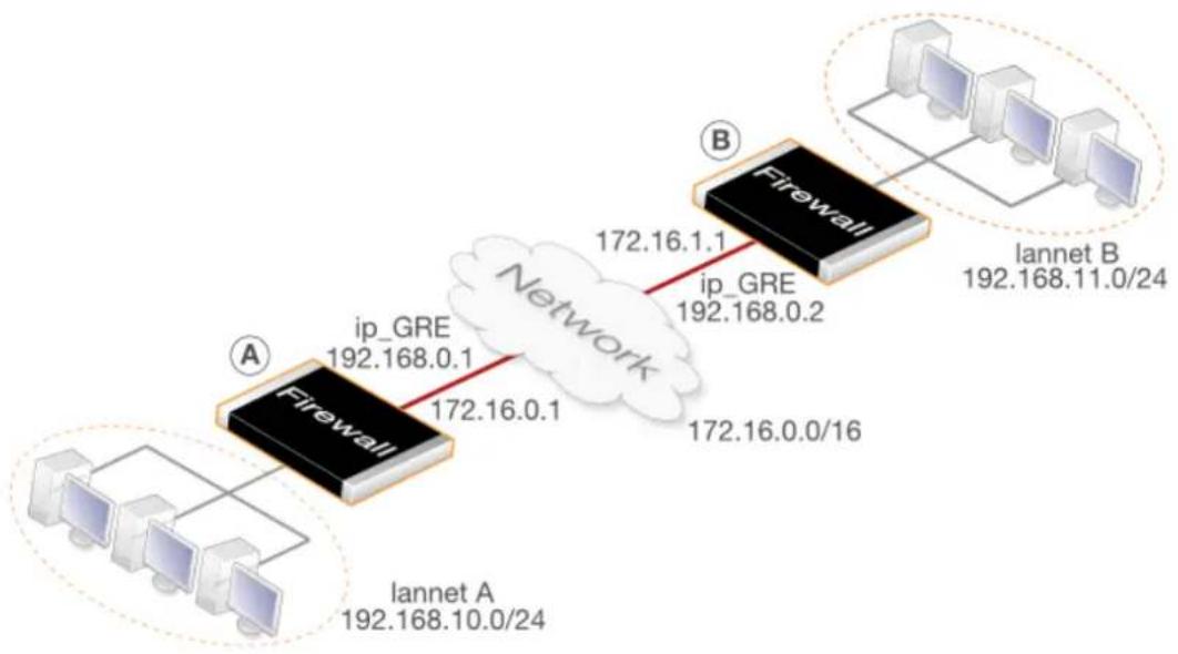
flowchart
graph TD
    A["Firewall"] -->|ip_GRE 192.168.0.1| B["Network"]
    A -->|172.16.0.1| B
    B -->|172.16.0.2 ip_GRE 192.168.0.2| C["Iannet B"]
    A -->|172.16.0.0/16| D["Iannet A"]
Figure 3.5. An Example of GRE Usage
Any traffic passing between A and B is tunneled through the intervening network using a GRE tunnel. Since the network is internal and not passing through the public Internet, there is no need for encryption.
Part 1. Setup for firewall A
Assuming that the network 192.168.10.0/24 is Iannet on the Ian interface, the steps for setting up NetDefendOS on A are:
-
In the address book set up the following IP objects:
-
remote_net_B: 192.168.11.0/24
- remote_gw: 172.16.1.1
-
ip_GRE: 192.168.0.1
-
Create a GRE Tunnel object called GRE_to_B with the following parameters:
-
IP Address: ip_GRE
-
Remote Network: remote_net_B
-
Remote Endpoint: remote_gw
-
Use Session Key: 1
• Additional Encapsulation Checksum: Enabled -
Define a route in the main routing table which routes all traffic to remote_net_B on the GRE_to_B GRE interface. This is not necessary if the option Add route for remote network is enabled in the Advanced tab, since this will add the route automatically.
- Create the following entries in the IP rule set that allow traffic to pass through the tunnel:
| Name | Action | Src Int | Src Net | Dest Int | Dest Net | Service |
| To_B Allow lan lannet GRE_to_B | remote_net_B | all_services | ||||
| From_B | Allow GRE_to_B | remote_net_B | lan lannet all_services |
Part 2. Setup for firewall B
Assuming that the network 192.168.11.0/24 is Iannet on the Ian interface, the steps for setting up NetDefendOS on B are as follows:
-
In the address book set up the following IP objects:
-
remote_net_A: 192.168.10.0/24
- remote_gw: 172.16.0.1
-
ip_GRE: 192.168.0.2
-
Create a GRE Tunnel object called GRE_to_A with the following parameters:
-
IP Address: ip_GRE
- Remote Network: remote_net_A
- Remote Endpoint: remote_gw
-
Use Session Key: 1
• Additional Encapsulation Checksum: Enabled -
Define a route in the main routing table which routes all traffic to remote_net_A on the GRE_to_A GRE interface. This is not necessary if the option Add route for remote network is enabled in the Advanced tab, since this will add the route automatically.
- Create the following entries in the IP rule set that allow traffic to pass through the tunnel:
| Name | Action | Src Int | Src Net | Dest Int | Dest Net | Service |
| To_A | Allow | lan | lannet | GRE_to_A | remote_net_A | all_services |
| From_A | Allow | GRE_to_A | remote_net_A | lan | lannet | all_services |
Checking GRE Tunnel Status
IPsec tunnels have a status of being either up or not up. With GRE tunnels in NetDefendOS this does not really apply. The GRE tunnel is up if it exists in the configuration.
However, we can check on the what is going on with a GRE tunnel. For example, if the tunnel is called gre_interface then we can use the ifstat CLI command:
gw-world:/> ifstat gre_interface
This will show us what is happening with the tunnel and the ifstat command options can provide various details.
3.4.8.6in4 Tunnels
A 6in4 Tunnel allows the tunneling of IPv6 traffic over networks that only support IPv4 traffic. In situations where an ISP can only provide an IPv4 public IP address, a host might still need to connect to the public Internet with an IPv6 address. This is solved by using 6in4 tunnels which are an implementation of RFC 4213 (Basic Transition Mechanisms for IPv6 Hosts and Routers). The 6in4 Tunnel configuration object provides this feature in NetDefendOS. It can be said that the D-Link firewall then acts as a 6in4 tunnel encapsulator.
A typical scenario for use of this feature is a protected network behind a firewall on which there are a number of IPv6 host computers. Each host will require its own unique IPv6 address and this address will be accessible to other hosts across the Internet. This IPv6 traffic will be sent through a single 6in4 tunnel which stretches from the firewall to a Tunnel Server (explained next). This is the scenario that will be discussed first in this section.
Tunnel Servers and Tunnel Brokers
A Tunnel Server is an external computer accessible through the Internet using IPv4 that provides a gateway for IPv6 traffic to the Internet. Tunnel servers are provided by Tunnel Brokers which are third party organizations that either charge for server use or provide the service for free. In some cases, an ISP may also offer this service.
Prerequisite Tunnel Broker Information
Before being able to configure a NetDefendOS 6in4 Tunnel object to an external tunnel server, the tunnel broker owning the server will provide the following information:
- An IPv6 prefix. This is the address range that can be used by the IPv6 hosts behind the firewall. Addresses can be statically assigned or assigned dynamically by configuring a NetDefendOS DHCPv6 server. A tunnel broker will have a large unique IPv6 prefix already assigned to them from which they make this allocation.
- The IPv4 address of an interface on the tunnel server computer. This is used as the Remote Endpoint property when configuring a 6in4 tunnel object. Instead of an IPv4 address, a DNS resolvable address could also be used in which case NetDefendOS will automatically resolve the address providing a DNS server has been configured.
- Optionally, the IPv6 address of the internal local endpoint of the tunnel at the client side can be provided by the broker. This is the IP Address property of the 6in4 Tunnel object. It can be pinged by the tunnel server to check if the tunnel is alive.
The diagram below illustrates a use case for IP6in4 tunnels with a tunnel broker. The LAN network and DMZ networks behind the D-Link firewall require IPv6 access to the Internet but only IPv4 access is available to the ISP's router.
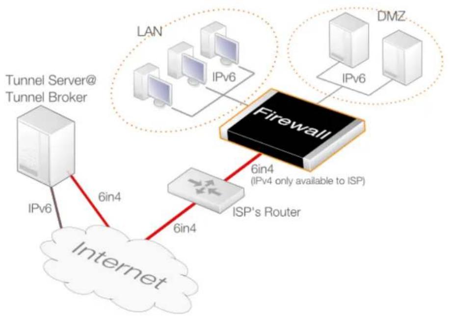
flowchart
graph TD
    A["Tunnel Server@ Tunnel Broker"] -->|IPv6| B["Internet"]
    B -->|6in4| C["Firewall"]
    C -->|6in4 (IPv4 only available to ISP)| D["ISP's Router"]
    D -->|6in4| E["Network"]
    F["LAN"] --> G["IPv6"]
    H["DMZ"] --> I["IPv6"]
    G --> J["Network"]
    I --> K["Network"]
Figure 3.6. IP6in4 Tunnel Usage
Configuring a 6in4 Tunnel Object
Apart from the name of the object, there are three key properties which must be assigned values:
- Remote Network
This specifies the network for the route that is added automatically by NetDefendOS when the tunnel object is defined. For the typical client scenario described here, this will usually be all-nets6 indicating the IPv6 gateway to the Internet.
If the option to add a route automatically is disabled, this property has no relevance since the network is specified in a manually added route.
The interface which is the local endpoint for the tunnel will be derived from a route lookup of this property. In most cases the default route to the Internet will be looked up and the interface will be the Ethernet interface connected to an ISP.
- IP Address
This is the local IPv6 address inside the tunnel. It may be provided by the tunnel broker in which case it can be pinged to establish if the tunnel is alive. If this is the case then the appropriate NetDefendOS IP rule or policy needs to be set up so that the ICMP ping is answered.
If the broker does not require a specific address then this should be set to any IPv6 address which belongs to the prefix handed out by the broker.
- Remote Endpoint
This is the IPv4 address for the tunnel server so NetDefendOS knows how to contact it across the Internet. It is assumed that NetDefendOS has access to the Internet via an ISP for IPv4 traffic only.
Example 3.26. 6in4 Tunnel Configuration
In this example, a 6in4 Tunnel object will be configured to connect with a remote tunnel server across the Internet.
It is assumed that a number of address objects have already been configured in the NetDefendOS address book. These have the names local_endpoint_ip6 for the local inner IPv6 endpoint of the tunnel and tunnel_server_ip4 for the IPv4 address of the tunnel server.
Command-Line Interface
gw-world:/> add Interface IP6in4Tunnel my_6in4_tunnel
    IP=local_endpoint_ip6
    Network=all-nets6
    RemoteEnpoint=tunnel_server_ip4
Web Interface
- Go to: Network > Interfaces and VPN > 6in4 > Add > 6in4 Tunnel
-
Enter the following:
-
Name: my_6in4_tunnel
- IP Address: local_endpoint_ip6
- Remote Network: all-nets6
-
Remote Endpoint: tunnel_server_ip4
-
Click OK
Routing Table Usage with 6in4 Tunnels
By default, the lookup of the IPv4 remote endpoint is done in the NetDefendOS main routing table. This can be changed to be a specific routing table. The route for the Remote Network property of the tunnel is also added, by default, to all routing tables including the main table. This can also be changed so that the addition is made to a specific routing table.
MTU resizing
The MTU used by the protected IPv6 clients should not be too large since this will result in excessive fragmentation during the tunneling process and thereby introduce unnecessary overhead. There are two ways that the IPv6 clients behind a firewall can have their MTU value adjusted:
- If the Pass returned ICMP error messages from destination property is enabled for the Service objects used by the IP rule set entries controlling traffic flow, the IPv6 hosts will initially take on the default MTU property of the 6in4 Tunnel object. By default this is 1280 which is the minimum value for IPv6. If other downstream network equipment requires a different MTU, this can also be communicated via ICMP messages.
• A NetDefendOS Router Advertisement object can be configured on the interface connected to
the IPv6 hosts and this can provide the preferred MTU value. This method provides the fastest response by the hosts since they do not have to resend after receiving ICMP error messages because of an unsuitable MTU size.
These options can be used together so that the router advertisement provides the initial MTU and if that is not acceptable, preferred MTU values are sent to the hosts via ICMP error messages.
NetDefendOS Acting as Tunnel Server
It has been assumed so far that NetDefendOS is acting as the client for an external tunnel server. However, the D-Link firewall itself can be a tunnel server. A typical usage of this is where clients at the branch offices of a company require IPv6 access. This is illustrated in the diagram below:
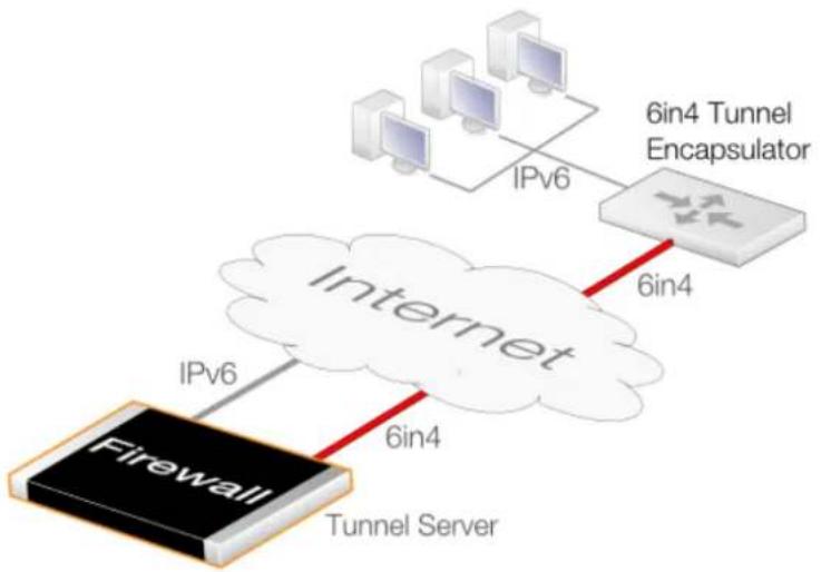
flowchart
graph TD
    A["Firewall"] -->|IPv6| B["Internet"]
    B -->|6in4| C["6in4 Tunnel Encapsulator"]
    C -->|IPv6| D["Server"]
    style A fill:#000,stroke:#fff,color:#fff
    style B fill:#fff,stroke:#000
    style C fill:#fff,stroke:#000
    style D fill:#000,stroke:#fff,color:#fff
Figure 3.7. Acting as a 6in4 Tunnel Server
The 6in4 tunnel encapsulator in the above diagram can be any piece of network equipment capable of 6in4 tunneling for the remote network traffic. This could be a router, a server with appropriate software, or a D-Link firewall set up as described previously.
To set up NetDefendOS to provide this tunnel server function, the following configuration components are required:
• A 6in4 Tunnel object for each tunnel that will connect carrying the IPv6 traffic of remote hosts.
- An all-net6 route for an interface that is connected to an ISP gateway that supports IPv6. Incoming IPv6 traffic from a tunnel can then be routed out onto the Internet via the interface in the route. This interface will usually be the Ethernet interface connected to an ISP but may be another type of interface.
- At least one IP rule set entry that allows traffic coming from the tunnel to exit using the all-net6 route. This must use a Service object that has its Pass returned ICMP errors messages from destination property enabled so that MTU sizes can be adjusted when required.
IP rule set entries controlling IPv6 traffic flow can optionally use the NetDefendOS Application Control feature to allow or deny specific types of IPv6 traffic. This is discussed further in Section 3.7, "Application Control".
Configuring NetDefendOS requires that a 6in4 Tunnel object is set up with the object properties being used in the following way:
- Remote Network
This is the IPv6 prefix used by the client hosts.
- IP Address
The inner IPv6 address of the endpoint local to this broker firewall. This address should not be accessible by anything else. NetDefendOS will automatically create a route for it that has core as the interface (in other words, a core route).
- Remote Endpoint
The IPv4 address of the connecting tunnel's remote Ethernet interface. This can also be a DNS-resolvable address.
When acting as a server, a single 6in4 Tunnel object can accept a connection from only one incoming tunnel. Separate tunnel objects must be configured for other incoming tunnels. ICMP error messages must also be allowed when NetDefendOS acts as a server so that MTU sizes can be correctly adjusted.
3.4.9. Loopback Interfaces
A Loopback Interface is a logical NetDefendOS interface that will take all traffic sent through it and send it out through a second configured loopback interface. Loopback interfaces are consequently always configured in pairs, with each referring to the other.
For example, suppose a pair of Loopback Interface objects are configured called LB1 and LB2 and each is defined to be paired with the other. When traffic is sent through the LB1 interface, it is simultaneously received on the LB2 interface with the transfer occurring virtually, entirely within NetDefendOS. Similarly, when traffic is sent through LB2, it is received on LB1. This is exactly the same as if the two interfaces were two physical Ethernet interfaces which are connected to each other.
IPv6 can be used with a Loopback Interface
Loopback interfaces can be used with both IPv4 and IPv6 traffic. A Loopback Interface object must always have an IPv4 address and network assigned to it. By turning on the Enable IPv6 property of a Loopback Interface object, an IPv6 address and network can also be defined, in addition to the mandatory IPv4 information. The grouping of both IPv4 and IPv6 address information in a Loopback Interface object does not imply any relationship between them. IPv6 loopback addresses are defined this way for configuration simplicity.
Loopback Interface Usage with Virtual Routing
Loopback interfaces are usually used with NetDefendOS Virtual Routing. In virtual routing, it is possible to divide up a single D-Link firewall's operations so that it behaves as multiple virtual firewalls. This is done by having multiple routing tables so that each table handles the routing for one set of interfaces.
In virtual routing, the routing tables and their associated routes can be totally isolated from each other so that related traffic flows are completely separate. However, if certain traffic needs to flow between interfaces in separate routing tables, a loopback interface pair must be used (also see Section 4.6, "Virtual Routing").
Loopback Interface Parameters
The following are the properties can be specified for a loopback interface:
| Name | The logical name of the interface for display and reference in NetDefendOS. |
| Loop To | This is the name of the other loopback interface in the pair. The other interface will have this loopback interface for its Loop to property.For each pair, the Loop to property must be left blank when the first interface is created and then filled in later after its partner is created. |
| IP Address | The IPv4 address assigned to the loopback interface. This is the address that can be "Pinged" and can be used as the source address for dynamically translated connections. This address can be any IP from the Network assigned to the interface but must be different from the address assigned to the other interface in the loopback pair. |
| Network | The network assigned to the loopback interface and to which the above IP Address belongs. This does not have to be the same network as the other interface in the loopback pair. |
| Enable IPv6 | If enabled, this option allows an IPv6 address and network to be entered. Entering some IPv4 address and network is mandatory even if IPv4 is not going to be used in the loopback setup. |
One of two options can then be selected depending on how the loopback interface is to be used with routing tables:
• Make the interface a member of all routing tables
Traffic arriving on this loopback interface will be routed according to the main routing table. A route for this loopback interface's IP address will be inserted automatically into all routing tables.
• Make interface a member of a specific routing table
With this option, a single route for this interface's IP will be inserted automatically into the specified routing table. Only the specified routing table will then be used for route lookups for traffic arriving on this interface.

Note: Routing rules can override table section
The above settings for route lookup can be overridden by a Routing Rule that triggers for the traffic.
Only the Route for the IP Address is Added Automatically
Although routes are inserted automatically into routing tables when loopback interfaces are created, this is only done for the loopback interface's IP address property. Other routes may have to be added manually. For example, a route may need to be added manually which associates a loopback interface with the network all-nets if the interface provides access to the Internet.
Loopback Interface IP Addresses
Loopback interfaces are configured with IP addresses, just as with any other interface type. The following should be noted for the IPv4 address assigned to the IP Address property assigned to a Loopback Interface object:
- The IPv4 addresses can be fictitious and the addresses for the an interface pair can be on the same network, although they must not be the same.
- The IP address assigned to a loopback interface is used as the source address for any address translation that IP rule set entries specify.
- If address translation is not used, it is recommended to set the interface's IP address to an IP in the range of the standard loopback IPv4 addresses. This is within the 127.0.0.0 to 127.255.255.255. For example, 127.0.1.1.
A Use Case for Loopback Interfaces
For this use case, consider a single D-Link firewall like the one below, that has one protected local network called LAN1. The route to this network is contained in a single routing table called RT1 which is isolated from all other routing tables with its Ordering parameter set to Only.
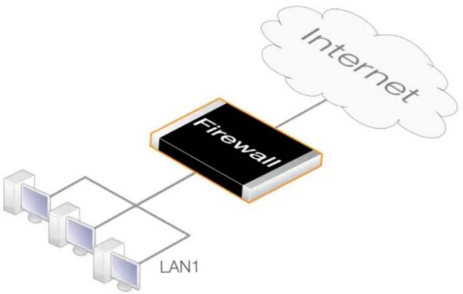
flowchart
graph TD
    A["Internet"] --> B["Firewall"]
    B --> C["Computer 1"]
    B --> D["Computer 2"]
    B --> E["Computer 3"]
    B --> F["LAN1"]
Figure 3.8. A Use Case for Loopback Interfaces
The firewall is also connected to the Internet but the all-nets route to the Internet is in a totally separate and similarly isolated routing table called RT2. In this situation there is no way for clients on LAN1 to reach the Internet since there is no all-nets route in RT1.
For LAN1 clients to have access to the Internet, loopback interfaces must be used and the setup process can be summarized into three parts:
- Define a loopback interface pair with membership in different routing tables.
- Define routes which route traffic to the loopback interfaces.
- Define IP rule set entries that allow traffic to flow to and from the loopback interfaces.
The diagram below illustrates this setup.
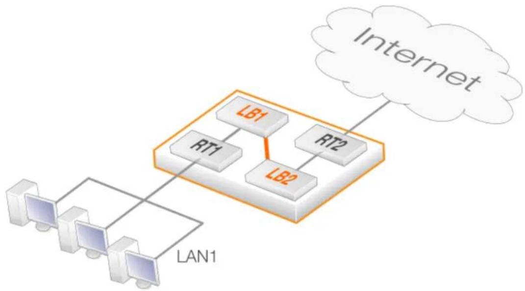
flowchart
graph TD
    Internet["Internet"] -->|LAN1| Router1["Router"]
    Router1 -->|RT1| Router2["Router"]
    Router2 -->|LT1| Router1
    Router2 -->|LT2| Router1
    Router1 -->|LB1| Router2
    Router2 -->|LB2| Router1
Figure 3.9. Setting Up Loopback Interfaces with Routing Tables
A more detailed description of these steps is as follows:
-
Create a pair of loopback interfaces called LB1 and LB2, each has the other as its Loop to parameter. Also define LB1 as a member of routing table RT1 and LB2 as a member of RT2.
-
Two configuration additions are now needed:
i. Define a route in RT1 that routes all-nets traffic (traffic to the Internet) to the loopback interface LB1.
ii. Define an IP rule set entry that allows Internet traffic to flow from LAN1 to LB1.
- The Internet traffic that is sent through loopback interface LB1 will automatically arrives at its partner LB2. Because LB2 is a member of the routing table RT2 that contains the all-nets route, traffic can be successfully routed to the Internet.
However, two additions are still needed:
i. An IP rule set entry needs to be defined which allows traffic to flow from LB2 to the Internet. This could be in the same IP rule set as the previous rule and will probably be a NAT rule which makes use of a single external IP address.
ii. A route needs to be defined which routes LAN1 traffic on the LB2 interface. This is needed for traffic returning from the Internet.
The relationship of loopback interfaces with the routing tables and networks in this example is illustrated below.
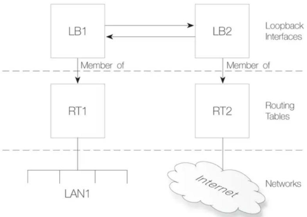
flowchart
graph TD
    A["LB1"] -->|Member of| B["RT1"]
    C["LB2"] -->|Member of| D["RT2"]
    B --> E["LAN1"]
    D --> F["Internet"]
    style A fill:#f9f,stroke:#333
    style C fill:#f9f,stroke:#333
    style B fill:#ccf,stroke:#333
    style D fill:#ccf,stroke:#333
    style E fill:#fff,stroke:#333
    style F fill:#fff,stroke:#333
Figure 3.10. Components of Loopback Interface Setup
Example 3.27. Creating a Loopback Interface Pair
This example shows how to create a loopback interface pair called LB1 belonging to the RT1 routing table and LB2 belonging to the RT2 routing table.
LB1 will have the IPv4 address 127.0.6.1 and network 127.0.6.0/24. LB2 will have the IPv4 address 127.0.5.1/24 and network 127.0.5.0/24.
Traffic routed by the RT1 table into the LB1 interface will now exit on the LB2 interface and be then routed using the RT2 routing table.
Command-Line Interface
A. Create the first loopback interface:
gw-world:/> add Interface LoopbackInterface LB1
IP=127.0.5.1
Network=127.0.5.0/24
MemberOfRoutingTable=RT1
B. Create the second loopback interface:
gw-world:/> add Interface LoopbackInterface LB2
IP=127.0.6.1
Network=127.0.6.0/24
LoopTo=LB1
MemberOfRoutingTable=RT2
C. Now, return to the first loopback interface and set the LoopTo property:
gw-world:/> set Interface LoopbackInterface LB1 LoopTo=LB2
3.4.10. Interface Groups
Any set of NetDefendOS interfaces can be grouped together into an Interface Group. This then acts as a single NetDefendOS configuration object which can be used in creating security policies in the place of a single group. When a group is used, for example as the source interface for an IP rule set entry, any of the interfaces in the group could provide a match for the rule.
A group can consist of ordinary Ethernet interfaces or it could consist of other types such as VLAN interfaces or VPN Tunnels. Also, the members of a group do not need to be of the same type. A group might consist, for example, of a combination of two Ethernet interfaces and four VLAN interfaces.
The Security/Transport Equivalent Option
When creating an interface group, the option Security/Transport Equivalent can be enabled (it is disabled by default). Enabling the option means that the group can be used as the destination interface in NetDefendOS rules where connections might need to be moved between two interfaces. For example, the interface might change with route failover or OSPF.
If a connection is moved from one interface to another within a group and Security/Transport Equivalent is enabled, NetDefendOS will not check the connection against the NetDefendOS rule sets with the new interface.
With the option disabled, a connection cannot be moved to another interface in the group and is instead dropped and must be reopened. This new connection is then checked against the NetDefendOS rule sets. In some cases, such as an alternative interface that is much slower, it may not be sensible to allow certain connections over the new interface.
Example 3.28. Creating an Interface Group
Command-Line Interface
gw-world:/> add Interface InterfaceGroup examplegroup Members=exampleIf1, exampleIf2
Web Interface
-
Go to: Network > Interfaces and VPN > Interface Groups > Add > InterfaceGroup
-
Enter the following information to define the group:
• Name: The name of the group to be used later
- Security/Transport Equivalent: If enabled, the interface group can be used as a destination interface in rules where connections might need to be moved between the
interfaces.
• Interfaces: Select the interfaces to be in the group
- Click OK
3.4.11. Layer 2 Pass Through
On some interface types, NetDefendOS provides the ability to enable layer 2 pass through either or both DHCP and non-IP protocols. Both are disabled by default but can be enabled on the following interface configuration types:
- Ethernet
• VLAN - Link Aggregation
• L2TPv3
In order for these options to functions, transparent mode must also be enabled directly on the interface (it should not be enabled by manually adding switch routes).

Note: L2TPv3 interfaces do not need transparent mode enabled
L2TPv3 interfaces in a NetDefendOS configuration do not have a property for enabling transparent mode so this does not need to be enabled first before enabling DHCP or non-IP protocol passthrough.
As shown in the example below, pass through can be enabled separately or together for the following:
Example 3.29. Enabling Layer 2 Pass Through
This example enables transparent mode as well as DHCP pass through and non-IP protocol passthrough on the interface if1.
Command-Line Interface
gw-world:/> set Interface Ethernet if1
AutoSwitchRoute=yes
DHCPPassthrough=Yes
NonIPPassthrough=Yes
Web Interface
- Go to: Network > Interfaces and VPN > Ethernet
- Select the interface if1.
- Enter the following:
-
Enable Enable Transparent Mode
-
Enable DHCP passthrough
-
Enable L2 passthrough for non-IP protocols
-
Click OK
3.5. ARP
3.5.1. Overview
Address Resolution Protocol (ARP) allows the mapping of a network layer protocol (OSI layer 3) address to a data link layer hardware address (OSI layer 2). In data networks it is used to resolve an IPv4 address into its corresponding Ethernet address. ARP operates at the OSI layer 2, data link layer, and is encapsulated by Ethernet headers for transmission.

Tip: OSI Layers
See Appendix D, The OSI Framework for an overview of the different OSI layers.
IP Addressing Over Ethernet
A host in an Ethernet network can communicate with another host only if it knows the Ethernet address (MAC address) of that host. Higher level protocols such as IP make use of IP addresses which are fundamentally different from a lower level hardware addressing scheme like the MAC address. ARP is used to retrieve the Ethernet MAC address of a host by using its IP address.
When a host needs to resolve an IPv4 address to the corresponding Ethernet address, it broadcasts an ARP request packet. The ARP request packet contains the source MAC address, the source IPv4 address and the destination IPv4 address. Each host in the local network receives this packet. The host with the specified destination address, sends an ARP reply packet to the originating host with its MAC address.
3.5.2. The ARP Cache
The ARP Cache in network equipment, such as switches and firewalls, is an important component in the implementation of ARP. It consists of a dynamic table that stores the mappings between IP addresses and Ethernet MAC addresses.
NetDefendOS uses an ARP cache in exactly the same way as other network equipment. Initially, the cache is empty at NetDefendOS startup and becomes populated with entries as traffic flows.
The typical contents of a minimal ARP Cache table might look similar to the following:
| Type IPv4 Address Ethernet | Address Expires | ||
| Dynamic 192.168.0.10 08:00:1 | 0:0f:bc:a5 45 | ||
| Dynamic 193.13.66.77 0a:46:4 | 2:4f:ac:65 136 | ||
| Publish | 10.5.16.3 4a:32:12:6c:89:a4 | - |
The explanation for the table contents are as follows:
- The first entry in this ARP Cache is a dynamic ARP entry which tells us that IPv4 address 192.168.0.10 is mapped to an Ethernet address of 08:00:10:0f:bc:a5.
- The second entry in the table dynamically maps the IPv4 address 193.13.66.77 to Ethernet address 0a:46:42:4f:ac:65.
- The third entry is a static ARP entry binding the IPv4 address 10.5.16.3 to Ethernet address 4a:32:12:6c:89:a4.
The Expires Column
The third column in the table, Expires, is used to indicate how much longer the ARP entry will be valid for.
For example, the first entry has an expiry value of 45 which means that this entry will be rendered invalid and removed from the ARP Cache in 45 seconds. If traffic is going to be sent to the 192.168.0.10 address after the expiration, NetDefendOS will issue a new ARP request.
The default expiration time for dynamic ARP entries is 900 seconds (15 minutes). This can be changed by modifying the advanced setting ARP Expire.
The advanced setting ARP Expire Unknown specifies how long NetDefendOS will remember addresses that cannot be reached. This limit is needed to ensure that NetDefendOS does not continuously request such addresses. The default value for this setting is 3 seconds.
Example 3.30. Displaying the ARP Cache
The contents of the ARP Cache can be displayed from within the CLI.
Command-Line Interface
gw-world:/> arp -show
ARP cache of iface lan
Dynamic 10.4.0.1 = 1000:0000:4009 Expire=196
Dynamic 10.4.0.165 = 0002:a529:1f65 Expire=506
Flushing the ARP Cache
If a host in a network is replaced with new hardware and retains the same IP address then it will probably have a new MAC address. If NetDefendOS has an old ARP entry for the host in its ARP cache then that entry will become invalid because of the changed MAC address and this will cause data to be sent to the host over Ethernet which will never reach its destination.
After the ARP entry expiration time, NetDefendOS will learn the new MAC address of the host but sometimes it may be necessary to manually force the update. The easiest way to achieve this is by flushing the ARP cache. This deletes all dynamic ARP entries from the cache and forces NetDefendOS to issue new ARP queries to discover the MAC/IP address mappings for connected hosts.
Flushing can be done with the CLI command arp -flush.
Example 3.31. Flushing the ARP Cache
This example shows how to flush the ARP Cache from within the CLI.
Command-Line Interface
gw-world:/> arp -flush
ARP cache of all interfaces flushed.
The Size of the ARP Cache
By default, the ARP Cache is able to hold 4096 ARP entries at the same time. This is adequate for most scenarios but on rare occasions, such as when there are several very large LANs directly connected to the firewall, it may be necessary to adjust this value upwards. This can be done by modifying the ARP advanced setting ARP Cache Size.
Hash tables are used to rapidly look up entries in the ARP Cache. For maximum efficiency, a hash table should be twice as large as the entries it is indexing, so if the largest directly connected LAN contains 500 IP addresses, the size of the ARP entry hash table should be at least 1000. The administrator can modify the ARP advanced setting ARP Hash Size to reflect specific network requirements. The default value of this setting is 512.
The setting ARP Hash Size VLAN setting is similar to the ARP Hash Size setting, but affects the hash size for VLAN interfaces only. The default value is 64.
3.5.3. ARP Publish
Overview
NetDefendOS supports the publishing of IP addresses on interfaces other than the one the IP address is actually connected to. This can optionally be done along with a specific MAC address instead of the publishing interface's MAC address. NetDefendOS will then send out ARP replies for ARP requests received on the interface for the published IP addresses. This feature is referred to in NetDefendOS as ARP Publish.
Usage
ARP publish may be used for a variety of reasons, such as the following:
• To give the impression that an interface in NetDefendOS has more than one IP address.
This is useful if there are several separate IP spans on a single LAN. The hosts on each IP span may then use a gateway in their own span when these gateway addresses are published on the corresponding NetDefendOS interface.
- Another use is publishing multiple addresses on an external interface, enabling NetDefendOS to statically address translate traffic to these addresses and send it onwards to internal servers with private IPv4 addresses.
- A less common purpose is to aid nearby network equipment responding to ARP in an incorrect manner.
Methods of Enabling ARP Publishing
ARP publishing is enabled in one of the following ways:
- An ARP object can be created for any interface by defining a single address which is to be ARP published on that interface.
- When a static route is created for an IPv4 address or network, the route option called Proxy ARP can be used to publish the address or network on all or selected interfaces.
Using ARP objects, single IP addresses only can be published one at a time. However, the Proxy ARP feature can publish entire networks. It also provides a single step to publish on all interfaces.
Proxy ARP is covered in Section 4.2.6, "Proxy ARP" and is not discussed further in this section.
ARP Object Properties
An ARP object has the following properties:
Mode The type of ARP object. As explained above, this can be one of:
• Static - Create a fixed mapping in the local ARP cache.
- Publish - Publish an IP address on a particular MAC address (or this interface).
- XPublish - Publish an IP address on a particular MAC address and "lie" about the sending MAC address of the Ethernet frame containing the ARP response.
Interface The local physical Ethernet interface for the ARP object.
IP Address The IP address for the MAC/IP mapping.
MAC Address The MAC address for the MAC/IP mapping. If it is omitted, the MAC address of the Ethernet interface is used.
The three publishing mode options for ARP objects of Static, Publish and XPublishare further explained next.
Static Mode ARP Objects
A Static ARP object inserts a mapping into the NetDefendOS ARP cache which connects a specified IP address with the associated Ethernet interface's MAC address.
This mode is not for publishing the address for external devices but rather for telling NetDefendOS itself how to reach external devices. A static ARP entry tells NetDefendOS that a specific IP address can be reached through a specific interface using a specific MAC address. This means, that when NetDefendOS wants to communicate with the address, it consults the ARP table static entries and can determine that it can be reached at a specific MAC address on a specific interface.
The most frequent use of static ARP objects is in situations where some external network device is not responding to ARP requests correctly and is reporting an incorrect MAC address. Some network devices, such as wireless modems, can have these problems.
It may also be used to lock an IP address to a specific MAC address for increasing security or to avoid denial-of-service if there are rogue users in a network. However, such protection only applies to packets being sent to that IP address. It does not apply to packets being sent from that IP address.
Publish and XPublish Modes
With Publish and XPublish modes, the ARP object creates an association between an IP address and a MAC address for publishing on the interface to external devices.
If the MAC address is not specified, the MAC address of the associated Ethernet interface is used.
The Difference Between Publish and XPublish Modes
To understand the difference between Publish and XPublish it is necessary to understand that when NetDefendOS responds to an ARP query, there are two MAC addresses in the Ethernet frame sent back with the ARP response:
- The MAC address in the Ethernet frame of the Ethernet interface sending the response.
- The MAC address in the ARP response which is contained within this frame. This is usually the same as (1) the source MAC address in the Ethernet frame but does not have to be.
These are shown in the illustration below of an Ethernet frame containing an ARP response:
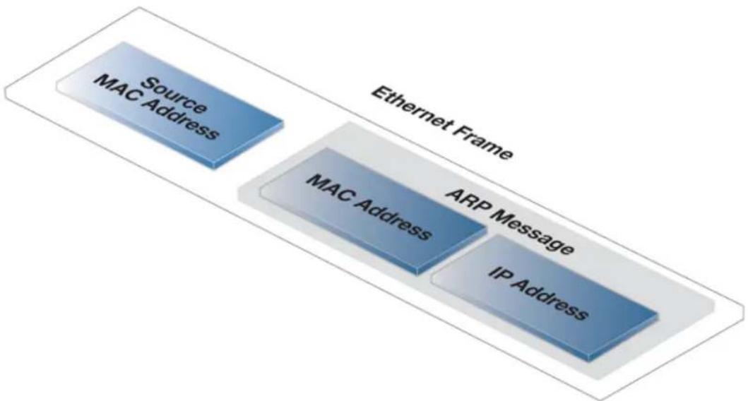
flowchart
graph LR
    A["Source MAC Address"] --> B["ARP Message"]
    B --> C["IP Address"]
    style A fill:#333,stroke:#fff,color:#fff
    style B fill:#333,stroke:#fff,color:#fff
    style C fill:#333,stroke:#fff,color:#fff
Figure 3.11. An ARP Publish Ethernet Frame
The Publish option uses the real MAC address of the sending interface for the address (1) in the Ethernet frame.
In rare cases, some network equipment will require that both MAC addresses in the response (1 and 2 above) are the same. In this case XPublish is used since it changes both MAC addresses in the response to be the published MAC address. In other words, XPublish "lies" about the source address of the ARP response.
If a published MAC address is the same as the MAC address of the physical interface, it will make no difference if Publish or XPublish is selected, the result will be the same.
ARP and Neighbor Discovery
Neighbor Discovery with IPv6 is the equivalent of ARP with IPv4. For this reason, ARP and neighbor discovery are combined in The graphical interface to NetDefendOS uses the same dialog to add either one. Neighbor Discovery is discussed further in Section 3.2, "IPv6 Support".
Example 3.32. Defining an ARP/Neighbor Discovery Object
This example will create a static mapping between IPv4 address 192.168.10.15 and Ethernet
address 4b:86:f6:c5:a2:14 on the lan interface:
Command-Line Interface
gw-world:/> add ARPND Interface=lan
    IP=192.168.10.15
    Mode=Static
    MACAddress=4b-86-f6-c5-a2-14
Web Interface
- Go to: Network > Interfaces and VPN > ARP/NeighborDiscovery > Add > ARP/NeighborDiscovery
-
Select the following:
-
Mode: Static
-
Interface: Ian
-
Enter the following:
• IP Address: 192.168.10.15
• MAC: 4b-86-f6-c5-a2-14
- Click OK
3.5.4. The Neighbor Cache
It is possible to use a feature called the neighbor cache to get additional information about the devices connected directly to the firewall. This cache takes information from the ARP cache and supplements it with additional details about connected devices. The neighbor cache can be retrieved in one of the following ways:
• Using the Web Interface
The Web Interface can display the cache in table form by going to:
Status > Sub Systems > Neighbor Devices.
- Use the CLI
The CLI command neighborcache will display the cache in table form.
• The REST API
The REST API can be used by software running on an external computer to retrieve the contents of the cache in JSON format. This is discussed further in the separate NetDefendOS REST API Guide.
Values Displayed from the Neighbor Cache
The following values can be retrieved from the neighbor cache:
- Interface
This is the local NetDefendOS interface that is connected to the external device.
- MAC Address
This is the MAC address of the external device. However, this value can either be a numeric MAC address of the name of the first Ethernet Address object in the local configuration which contains the same MAC address as the device.
For an Ethernet Address object name to be displayed instead of the numeric MAC address, the administrator must create such an object in the configuration with the relevant MAC address. These objects are discussed further in Section 3.1.3, "Ethernet Address Objects".
• Vendor
The name of the vendor, normally a company name, that is usually associated with the MAC address.
- IPv4 Address/IPv6 Address
The IPv4 or IPv6 address of the external device.
- Authenticated User
If NetDefendOS authentication took place when the device connected then this will be the username that was used with the authentication process.
- DHCP Hostname
This value may be included if the external device was allocated its IP address by NetDefendOS acting as a DHCP server. The hostname will be the name sent by the external device in its DHCP request for an IP address. If it did not send a name in the request, the hostname value will not be included.
- Status
This can take the value Active or Inactive depending on whether any recent traffic was seen to or from the device.
- Timeout
If the status is Inactive then this is the number of seconds since the last traffic was seen. In the Web Interface, this value is shown alongside the status in minutes and seconds.
Using the neighborcache CLI Command
The neighborcache command can be used in the CLI to show the information listed above. However, the command with no options does not show all values. For example:
gw-world:/> neighborcache
Contents of Active Neighbor Cache [Active:1]
Idx Iface HW Address IP4 Address State Timeout Vendor
1 wan 00-50-8B-E9-46-5E 203.0.113.5 Active 0 Mega Corp.
2 lan 40-45-D1-61-02-7B 192.168.188.1 Inactive 171954 D-Link
The authenticated users are not shown in this default display but can be shown with the -users options:
gw-world:/> neighborcache -users
Similarly, if the DHCP host name is to be displayed, use the -names option:
gw-world:/> neighborcache -names
3.5.5. ARP Advanced Settings
This section presents some of the advanced settings related to ARP. In most cases, these settings need not to be changed, but in some deployments, modifications might be needed.
A complete list of all ARP advanced settings can be found in the separate NetDefendOS CLI Reference Guide under the object name ARPNDSettings.
Multicast and Broadcast
ARP requests and ARP replies containing multicast or broadcast addresses are usually never correct, with the exception of certain load balancing and redundancy devices, which make use of hardware layer multicast addresses.
The default behavior of NetDefendOS is to drop and log such ARP requests and ARP replies. This can, however, be changed by modifying the advanced settings ARP Multicast and ARP Broadcast.
Unsolicited ARP Replies
It is possible for a host on a connected network to send an ARP reply to NetDefendOS even though a corresponding ARP request was not issued. This is known as an unsolicited ARP reply.
According to the ARP specification, the recipient should accept these types of ARP replies. However, because this could be a malicious attempt to hijack a connection, NetDefendOS will, by default, drop and log unsolicited ARP replies.
This behavior can be changed by changing the advanced setting Unsolicited ARP Replies to the value Accept (this setting is found in the Web Interface in Network > ARP/Neighbor Discovery > Advanced Settings).
ARP Requests
The ARP specification states that a host should update its ARP Cache with data from ARP requests received from other hosts. However, as this procedure can facilitate hijacking of local connections, NetDefendOS will normally not allow this.
To make the behavior compliant with the RFC 826 specification, the administrator can modify the setting ARP Requests. Even if this is set to Drop (meaning that the packet is discarded without being stored), NetDefendOS will reply to it provided that other rules approve the request.
Changes to the ARP Cache
A received ARP reply or ARP request can possibly alter an existing entry in the ARP cache.
Allowing this to take place may allow hijacking of local connections. However, not allowing this may cause problems if, for example, a network adapter is replaced since NetDefendOS will not accept the new address until the previous ARP cache entry has timed out.
The advanced setting Static ARP Changes can modify this behavior. The default behavior is that NetDefendOS will allow changes to take place, but all such changes will be logged.
A similar issue occurs when information in ARP replies or ARP requests could collide with static entries in the ARP cache. This should not be allowed to happen and changing the setting Static ARP Changes allows the administrator to specify whether or not such situations are logged.
Sender IP 0.0.0.0
NetDefendOS can be configured for handling ARP queries that have a sender IP of 0.0.0.0. Such sender IPs are never valid as responses, but network units that have not yet learned of their IP address sometimes ask ARP questions with an "unspecified" sender IP. Normally, these ARP replies are dropped and logged, but the behavior can be changed by modifying the setting ARP Query No Sender.
Matching Ethernet Addresses
By default, NetDefendOS will require that the sender address at Ethernet level should comply with the Ethernet address reported in the ARP data. If this is not the case, the reply will be dropped and logged. The behavior can be changed by modifying the setting ARP Match Ethernet Sender.
3.6. IP Rule Sets
3.6.1. Rulesets Overview
Before examining IP rule sets in detail, the general concept of rule sets in a NetDefendOS configuration will be examined and then the details of IP rule sets will be discussed in detail.
The NetDefendOS rule sets that define NetDefendOS security policies include the following:
• IP Policies
IP Policy entries in IP rule sets are the principal means of determining which traffic is permitted to pass through the firewall as well as determining if the traffic is subject to address translation or application level processing by ALGs or other subsystems. The network filters for policies can be assigned either IPv4 or IPv6 addresses, but IPv4 and IPv6 cannot be combined in a single policy.
IP Policy objects come in a number of varieties with different usages. The following are the available types:
i. IP Policy - This is the generic equivalent to an IP Rule and provides traffic filtering with the option to apply a range of different actions to that traffic.
ii. SLB Policy - This is specifically for server load balancing and is described in Section 11.3, "Server Load Balancing".
iii. Stateless Policy - This is specifically for stateless traffic and can replace an IP Rule object with an Action of FwdFast. This is described further in Section 3.6.8, "Stateless Policy".
iv. Multicast Policy - This is specifically for multicast traffic and can replace an IP Rule object with an Action of Multicast SAT. This is described further in Section 4.8, "Multicast Routing".
IP Policy objects are implemented in the background by IP Rule objects and one IP Policy may correspond to more than one IP Rule. IP Policy objects are easier to use than IP Rule objects and are therefore the recommended means of controlling traffic flow. In addition, some newer NetDefendOS features can only be configured using policies.
• IP Rules
IP Rule objects are an alternative to IP Policy objects and are the building blocks on which IP Policy objects are built. They need only be used if there is a requirement for compatibility with older NetDefendOS versions.
Note that the usage of IP rules can be disabled (by default, usage is enabled) and how to do this is described in Section 3.6.9, "Creating IP Rules".
- Pipe Rules
These determine which traffic triggers traffic shaping to take place and are described in Section 11.1, "Traffic Shaping".
• Policy-based Routing Rules
These rules determine the routing table to be used by traffic and are described in Section 4.3, "Policy-based Routing". The network filter for these rules can be IPv4 or IPv6 addresses (but not both in a single rule).
- Authentication Rules
These determine which traffic triggers authentication to take place (source net/interface only) and are described in Chapter 9, User Authentication.
Common Rule Set Filtering Properties
The NetDefendOS rule sets described above are configured by the administrator to regulate which traffic can flow through the firewall as well as how traffic is examined and changed as it flows.
Entries in these rule sets share a nearly uniform means of specifying filtering criteria which determine the type of traffic to which they will apply. Each rule set entry, such as an IP Policy object, usually has the following mandatory filtering criteria:
- Source Interface
This is a filter for the interface on which the targeted traffic arrives. Note that any interface filter could be a physical Ethernet interface but it could also be a logical interface such as an IPsec tunnel or VLAN interface. The special value any can be used to mean any interface.
- Source Network
A filter for the source IP address of the targeted traffic. This could be a single IP address, a range, a set of ranges or an entire network. The predefined address object all-nets can be used to mean any IPv4 address or all-nets6 for any IPv6 address.
- Destination Interface
The destination interface through which the targeted traffic will flow out. Like Source Interface, this could be a physical or logical interface. The special value any can be used to mean any interface.
- Destination Network
A filter for the destination IP address of the targeted traffic. This could be a single IP address, a range, a set of ranges or an entire network. The predefined address object all-nets can be used to mean any IPv4 address or all-nets6 for any IPv6 address.
• Service
A Service object which specifies the type of protocol which will be targeted. The predefined service object all_services can be used to mean any protocol.
NetDefendOS provides a large number of predefined service objects but administrator defined custom services can also be created. Existing service objects can also be collected together into service groups.
- Geolocation
An optional Geolocation Filter object is available with the IP Policy family of IP rule set objects. This filter type specifies the targeted source and/or destination IP addresses according to the regions of the world they are associated with. If geolocation is not specified it defaults to all regions. This feature is discussed in detail in Section 3.6.3, "Using Geolocation".
Note that ALL of the filtering criteria must match in a logical AND operation for a rule set entry to trigger for a given traffic flow. As a rule of thumb, it is recommended to create as narrow a set of filtering criteria as possible for a single rule set entry so that only the intended traffic triggers that entry. This increases security and can also improve system performance.
Useful Special Objects and Values for Security Policy Filters
When specifying the filtering criteria in any of the NetDefendOS rule sets, the following are useful predefined objects and special values that can be used:
• Specifying All IPv4 Addresses
For a source or destination network, the predefined address book object called all-nets can be used to specify any IPv4 address. This is equivalent to the IPv4 address 0.0.0.0/0.
• Specifying All IPv6 Addresses
Like all-nets, the predefined address book object called all-nets6 specifies all IPv6 addresses and is equivalent to the IPv6 address ::/0. Note that this cannot be combined with IPv4 all-nets in a single rule set entry.
- Specifying Any Interface
For source or destination interface, the special value any can be used. This means that any interface will match the filter.
• The Core Interface
The destination interface can be specified as core. This means that traffic, such as an ICMP Ping, is destined for the D-Link firewall itself and NetDefendOS will respond to it.
New connections that are initiated by NetDefendOS itself do not need an explicit IP rule set entry for the reason that NetDefendOS itself is always trusted as a connection source and such connections are always allowed by default. For this reason, the interface core is not used as a source interface. Such trusted NetDefendOS connections include those needed to connect to the external databases needed for such NetDefendOS features as IDP and web content filtering.
• Specifying All Protocols for the Service Property
The Service property of a rule set entry can be specified as the predefined object all_services which includes all possible protocols.
• Specifying the Local Host IP Address
The IPv4 loopback addresses 127.0.0.1 can be specified using the predefined address object called localhost. The IPv6 loopback address ::1 can be specified using the predefined address book object called localhost6.
3.6.2. Creating IP Policies
An IP Policy object in an IP rule set is the most fundamental way to impose a security policy on traffic arriving and/or leaving a D-Link firewall. This section discusses how these objects can be added to a configuration.
The Initial IP Rule Set is Usually Empty
NetDefendOS always has a single IP rule set predefined called main. When NetDefendOS is started for the first time, there may be no IP rule set entries and all traffic is therefore dropped. In order to permit any traffic to traverse the firewall (as well as allowing NetDefendOS to respond to ICMP Ping requests), at least one IP rule set entry must exist (usually an IP Policy object) which allows it.
Use IP Policies Instead of IP Rules
IP policies are built on top of the more granular IP rules but hide the complexities of using IP rules, particularly for configuring ALG processing. For example, SAT translation requires more than one IP rule but can be achieved using a single IP policy. IP rules are still created in the background but the administrator is only aware of the IP policy object. IP rules should be used only when there is need for compatibility with an older NetDefendOS version.
If there is a need to see the IP rules that have created when an IP policy is defined, this can done with the following CLI command:
gw-world:/> rules
The rule -verbose command can be used to get the most detail for each IP rule created. The rules command only displays IP Rule objects.
IP Policies Must be Used for Certain Features
Certain features are only available with IP Policy objects and cannot be configured using IP rules. These include:
- Geolocation filtering of traffic. One of the traffic filtering options is to specify the location in the world where the traffic is coming from or going to.
- Using FQDN Address objects for the source or destination network. These are described further in Section 3.1.7, "FQDN Address Objects".
• Using the DNS and IMAP ALGs.
Creating IP Policies
An IP Policy object has the following basic filtering properties:
- Allow or Deny Action
An IP policy either allows a particular type of traffic or it denies it. The action Deny is equivalent to the action Drop in IP rules.
- Source/Destination Interface/Network Filter
This filter identifies the traffic of interest in the same way that an IP rule filter does.
- Geolocation
This filter identifies a specific predefined region or an administrator defined Geolocation Filter object which identifies a group of specific countries. The default value for geolocation is Everywhere (no place is excluded).
• Service
This identifies the type of protocol for the policy. When using an IP policy with certain options, only services that have the Protocol property set can be used. These are listed below.
- Policy Options
The traffic identified by the filter is subject to one or more of possible options. These are:
i. Logging - This is enabled or disabled.
ii. Anti-Virus - An Anti-Virus policy can be selected. This requires a Service object with the Protocol property set.
iii. Web Content Filtering - To enable this, a Web Profile object must be created and associated with the policy. In addition, a Service object must be used that has the Protocol property set to HTTP.
A Web Profile object can have one or more URL Filter objects defined as children objects. Each URL Filter can specify a URL or set of URLs (wildcarding is allowed) that are on a blacklist or whitelist.
iv. Application Control - Application control is enabled directly on an IP Policy. Any type of Service object can be used with this.
v. File Control - This can block or allow specific filetypes. Is is enabled by creating a new File Control Profile object and associating it with the IP Policy object. File control is only applicable to the HTTP, SMTP, POP3 and FTP protocols and requires using Service object with the Protocol property correctly set to the targeted protocol.
vi. Advanced Actions - It is possible to specify the Reject action for denied connections (no acknowledgment is sent to the source host).
ALG Options Require a Service with the Protocol Property Assigned
As mentioned previously, ALGs can be used with IP policies only if the associated Service object has its Protocol property set to the correct protocol value.
For example, if Web Content Filtering (WCF) is to be enabled with an IP Policy object then the associated Service object must have its Protocol property set to HTTP. This allows a Web Profile which configures WCF to be associated with the policy.
Application control is the one IP policy option which does not require the Service object to have its Protocol property set since application control does not make use of an ALG.
Routes Must Also Exist for Traffic Flow
An important point to remember is that even though an IP policy might allow traffic flow between interfaces, routes in the routing table for both the source and destination interfaces have to exist that route the source and destination IP addresses on those interfaces. This point is discussed in further in Section 3.6.4, "IP Rule Set Processing".
Example 3.33. IP Policy Setup to Allow LAN Connections to a DMZ
In this example, new client HTTP and HTTPS connections will be allowed from the lan_net network on the lan interface to a webserver located in the network dmz_net on the dmz interface. Both networks are assumed to be private IP networks so that no address translation is required.
The Service object used will be the predefined service called http-all which will allow both HTTP and HTTPS traffic. Its Protocol property does not need to be set to "HTTP" because no ALGs will be used with the traffic at this point.
Note that the Source Translation of the IP policy will be left at the default value of Auto in this example. This means that when both the source and destination IP addresses of a connection are private IP addresses then no translation will be performed. The Auto setting is explained further in Section 8.5, "Automatic Translation".
Command-Line Interface
gw-world:/> add IPPolicy Name=lan_to_dmz
SourceInterface=lan
SourceNetwork=lan_net
DestinationInterface=dmz
DestinationNetwork=dmz_net
Service=http-all
Action=Allow
Web Interface
-
Go to: Policies > Firewalling > Add > IP Policy
-
Now enter:
-
Name: lan_to_dmz
-
Action: Allow
-
Under Filter enter:
-
Source Interface: Ian
- Source Network: lan_net
- Destination Interface: dmz
-
Destination Network: dmz_net
• Service: http-all -
Select OK
Creating a Drop-All IP Rule Set Entry
Traffic that does not match any IP rule set entry is, by default, dropped by NetDefendOS. However, this automatically dropped traffic does not generate log messages. In order to be able to log the dropped connections, it is recommended that an explicit IP policy is defined that drops traffic for all source/destination networks/interfaces and this is placed as the last item in the rule set. This is often referred to as a Drop-All entry.

Tip: Include the rule set name in the drop-all name
There may be several IP rule sets in use. It is recommended to include the IP rule set name in the name of the drop-all entry so it can be easily identified in log messages.
For example, a drop-all entry in the main rule set could be called main_drop_all or similar.
The IP Addresses in IP Rule Set Entries can be IPv4 or IPv6
IP rule set entries support either IPv4 or IPv6 addresses as the source and destination network in the filtering properties.
However, both the source and destination network must be either IPv4 or IPv6. It is not permissible to combine IPv4 and IPv6 addresses in a single rule set entry. For this reason, two drop-all entries will be required when using IPv6, one for IPv4 and one for IPv6 as shown below:
| Name | Action | Source Iface | Source Net | Dest Iface | Dest Net | Service |
| DropAll Drop any all-nets any all-nets all_services | ||||||
| DropAll6 | Drop | any | all-nets6 | any | all-nets6 | all_services |
For further discussion of this topic, see Section 3.2, "IPv6 Support".
Example 3.34. Creating a Drop-All IP Policy
This example shows how to create an IP policy that can be placed at the end of the main IP rule set so that dropped connections can be logged. Logging will be enabled by default for an IP policy but turning on logging explicitly is included in the example for clarity.
Note that the Source Translation property of the IP policy can be left at the default value of Auto because no translation will ever be performed on traffic that is denied.
Command-Line Interface
gw-world:/> add IPPolicy Name=main_drop_all
SourceInterface=any
SourceNetwork=all-nets
DestinationInterface=any
DestinationNetwork=all-nets
Service=all_services
Action=Deny
LogEnabled=Yes
Web Interface
-
Go to: Policies > Firewalling > Main IP Rules > Add > IP Policy
-
Now enter:
-
Name: main_drop_all
• Action: Deny -
Under Filter enter:
• Source Interface: any
• Source Network: all-nets
• Destination Interface: any
• Destination Network: all-nets
• Service:all_services
- Under Logging & Comments enter:
- Logging: ON
- Click OK
3.6.3. Using Geolocation
An additional traffic filtering option that is only available in NetDefendOS IP Policy objects is Geolocation. This feature allows filtering of IPv4 and IPv6 addresses for the traffic's source and/or destination according to its geographic association. Some IP addresses may not have a known geographic association but these can also be targeted by this feature.
It should be noted that the geolocation feature is a standard part of NetDefendOS and does not require any subscription to function. The IP database it uses is embedded in NetDefendOS and may get updated when a newer version of NetDefendOS is installed.
Ways of Using Geolocation
The geolocation feature can be used in two ways with an IP Policy object:
- The Geolocation property for the source and/or destination IP address can be set so that matching traffic is allowed. This will cause traffic from matching geographic areas to be included.
- The Geolocation property for the source and/or destination IP address can be set so that matching traffic is dropped. This will exclude traffic from matching geographic areas.
Selecting a Geographic Area
The area selected in an IP Policy object as a filter can be one of the following two types:
• A predefined region
NetDefendOS provides a predefined list of large world regions. These regions consist of the following:
• Africa
• Antartica
• Asia
• Europe
• North America
• Oceana
• South America
By default, no filter is selected, which means that all regions are allowed (Anywhere).
• An administrator defined Geolocation Filter object
For finer control of the targeted geographic are, the administrator can create a Geolocation Filter object which consists of one or more targeted countries. This object can then be used as a value for the Geolocation property of an IP Policy.
In addition to specifying countries for a Geolocation Filter object, or instead of countries, the following two additional options can be added to the filter:
i. Match Private Networks - This includes the IP addresses used for private networks. This includes the IPv4 networks 10.0.0.0/, 172.16.0.0/12, 192.168.0.0/16 and the IPv6 network fd00::/8. Although this option is not directly related to geolocation and could be implemented through address book, it is provided as a convenience.
ii. Match Unclassified Networks - This will match any IP address that is public but does not have a known country association.

Tip: A web interface flag icon indicates geolocation is set
In the IP rule set summary which is displayed in the Web Interface, there is no separate column to indicate that geolocation is set on an IP policy. Instead, a flag icon will appear to the right of the IP network value in the Src Net and Dest Net columns.
Example 3.35. Setting up a Geolocation Filter
This example will set up an IP Policy object that will drop all Internet traffic coming from the mythical country of Hackerland. This is done by first creating a Geolocation Filter that includes only Hackerland. An IP Policy object is then set up which uses this filter as its source.
In addition, the IP Policy will also drop traffic that comes from any IP address that is not known to be associated with a country.
Note that the country Hackerland does not appear in the predefined list of countries and is only used here for the purpose of illustration.
Command-Line Interface
A. Create the GeolocationFilter object:
gw-world:/> add GeolocationFilter hackerland_filter
Countries=Hackerland
MatchUnknown=Yes
B. Next, create the IP Policy object that uses this filter:
gw-world:/> add IPPolicy Name=lan_to_dmz
SourceInterface=any
SourceNetwork=all-nets
DestinationInterface=any
DestinationNetwork=all-nets
Service=all_services
Action=Deny
Drop=Yes
SourceGeoFilter=hackerland_filter
Web Interface
A. Create the GeolocationFilter object:
-
Go to: Policies > Firewalling > Geolocation Filter > Add > Geolocation Filter
-
Now enter:
- Name: hackerland_filter
• Add the country Hackerland to the Selected list
- Enable Match unclassified networks
3. Click OK
B. Next, create the IP Policy object that uses this filter:
-
Go to: Policies > Firewalling > Add > IP Policy
-
Now enter:
-
Name: drop_hackerland
• Action: Deny -
Under Filter enter:
-
Denied Behavior: Drop
- Source Interface: any
- Source Network: all-nets
- Source Geolocation: hackerland_filter
- Destination Interface: any
- Destination Network: all-nets
-
Destination Geolocation: Anywhere
• Service: all_services -
Select OK
3.6.4. IP Rule Set Processing
Traffic Flow Needs an IP Rule Set Entry Plus a Route
When NetDefendOS is started for the first time, the default IP rule set is usually empty so at least one IP rule set entry usually has to be added to allow any traffic to flow through the firewall.
However, adding an IP rule set entry may not be enough because the following needs to be present:
- A route must exist in a NetDefendOS routing table which specifies on which interface packets should leave in order to reach their destination.
- A second route must also exist that indicates the source of the traffic is found on the interface where the packets enter.
- An IP rule set entry which allows the traffic to flow from its source network/interface to its destination network/interface
Typically, the entry is an IP Policy object, or a variant of that (such as a Stateless Policy).
Alternatively, an IP Rule could also do this if compatibility with older NetDefendOS versions is required.
The Network Address Object for an Interface Must Be Correct
Note that predefined routes already exist in the main routing table for all Ethernet interfaces. However, the predefined network address object for an interface (for example, wan_net) needs to have the appropriate value assigned to it for the route to be correct before traffic can flow through that interface
The default management interface will already have a predefined network assigned to its IP address object (for example, Ian_net). However, other network address objects will have a default value of 127.0.0.1 (the loopback address) so a network must be assigned to them before traffic can flow in conjunction with an IP policy.
Packet Flow Ordering
The order in which the above components are used is important. The route lookup occurs first to determine the exiting interface and then NetDefendOS looks for an IP rule set entry that allows the traffic to leave on that interface. If such an entry is not found then the traffic is dropped. This ordering is illustrated in the diagram below.
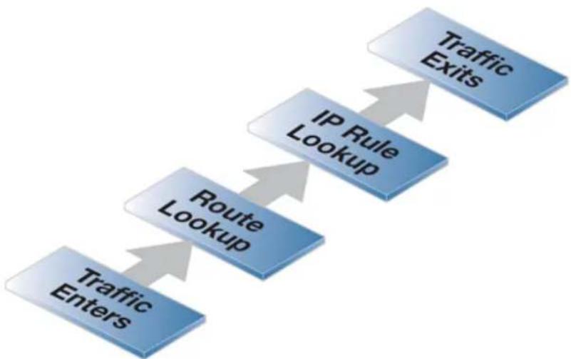
flowchart
graph TD
    A["Traffic Enters"] --> B["Route Lookup"]
    B --> C["IP Rule Lookup"]
    C --> D["Traffic Exits"]
Figure 3.12. Simplified NetDefendOS Traffic Flow
This description of traffic flow is a simplified version of the full flow description that can be found in Section 1.3, "NetDefendOS State Engine Packet Flow".
For example, before the route lookup is done, NetDefendOS first checks that traffic from the source network should, in fact, be arriving on the interface where it was received. This is done by NetDefendOS performing a reverse route lookup which means that the routing tables are searched for a route that indicates the network should be found on that interface.
This second route should logically exist if a connection is bidirectional and it must have a pair of routes associated with it, one for each direction.
IP Rule Set Scanning
When a new connection, such as a TCP/IP connection, is being established through the D-Link firewall, the IP rule set is scanned from the top to the bottom until an entry that matches the parameters of the new connection is found. The first matching entry's action is then performed.
If the matching IP rule set entry allows it, the establishment of the new connection will go ahead. If the matching entry is stateful (for example, an IP policy) a new entry or state representing the new connection will then be added to the NetDefendOS internal state table which allows monitoring of opened and active connections passing through the firewall. If the action is Deny then the new connection is refused.

Tip: Entries in the wrong order sometimes cause problems
It is important to remember the principle that NetDefendOS searches the IP rule set from top to bottom, looking for the first matching entry
If a particular rule set entry seems to be ignored, check that some other entry above it is not being triggered first.
Stateful Inspection
When a stateful IP rule set entry (for example, an IP Policy object) is triggered, subsequent packets belonging to that connection will not need to be evaluated individually against the rule set. Instead, a much faster search of the state table is performed for each packet to determine if it belongs to an established connection.
This approach to packet processing is known as stateful inspection and is applied not only to stateful protocols such as TCP but is also applied to stateless protocols such as UDP and ICMP by using the concept of "pseudo-connections". This approach means that evaluation against the IP rule set is only done in the initial opening phase of a connection. The size of the rule set therefore has negligible effect on overall throughput.
The First Matching Principle
If several rule set entries match the same filtering parameters, the first matching rule in a scan from top to bottom is the one that decides how the connection will be handled.
Non-matching Traffic
Incoming packets that do not match any rule in the rule set and that do not have an already opened matching connection in the state table, will automatically be subject to a Deny action but without logging. As mentioned previously, to be able to log non-matching traffic, it is recommended to create an explicit a Drop-All IP Policy as the final rule set entry with an action of Deny, with Source/Destination Network of all-nets and Source/Destination Interface set to all. This allows logging of traffic does not trigger any other entry.
Some IP Rule Set Actions Change TCP Sequence Numbers
In some situations with certain types of network equipment, the TCP sequence number needs to remain the same as data traffic traverses the firewall. It should therefore be noted that only the Stateless Policy rule set entry (or FwdFast IP rule) guarantees that the TCP sequence number is unaltered. Some actions, such as NAT, will change the TCP sequence number as traffic flows through NetDefendOS.
Logging
When an IP rule set entry is created, the default is that logging is enabled. This means that a log message is generated whenever the entry triggers. This behavior can be altered by disabling logging on the individual rule set entry.
Bi-directional Connections
An occasional mistake when setting up IP rule sets is to define two entries, one for traffic in one direction and another for traffic coming back in the other direction. This is not necessary in most cases if the IP rule set entry is stateful (for example, any IP Policy object is stateful).
The exception with this bi-directional flow is the Stateless Policy object (or FwdFast IP rule). If this is used, it allows traffic flow only in one direction. If bi-directional flow is required then two such stateless entries are needed, one for either direction.
IDENT and IP Rule Set Entries
Usually, when traffic is dropped by an IP rule set entry, no reply is sent back to the source IP. Sometimes, for example when responding at the IDENT user identification protocol, a "polite" reply is required. The is done with an IP Policy object by configuring the Action to be Deny and the Deny Behavior to be Reject (an Action of Reject with an IP rule).
3.6.5. Multiple IP Rule Sets
Overview
NetDefendOS allows the administrator to define multiple IP rule sets which can both simplify and provide greater flexibility when defining security policies. The default IP rule set is known as main and is always present in NetDefendOS. Additional rule sets can be defined as needed and are given a name by the administrator.
Multiple IP rule sets offer advantages which include the following:
- The administrator can break a single large IP rule set into multiple, smaller and more manageable rule sets which can make the configuration easier to understand.
- A single named IP rule set can be associated with a routing table. This makes implementing Virtual Routing much simpler since each router can have a dedicated IP rule set associated with it. See Section 4.6, "Virtual Routing" for more information about this topic.
- IP rule lookup speed can be increased for very large rule sets. This is done by breaking down a large rule set into several smaller ones. A Goto rule can then be used to jump to a new rule set for a given type of traffic and a Return rule can be used to jump back to the original rule set if no other rule set entry triggers.
Once a new IP rule set is created, IP rules and/or policies can be added to it in the normal way.
Example 3.36. Creating an IP Rule Set
In this example, a new IP Rule Set will be created and given the name dmz_rules. This rule set will be used in later examples and will contain all IP rules related to the DMZ.
Command-Line Interface
gw-world:/> add IPRuleSet dmz_rules
Web Interface
- Go to: Policies > Firewalling > Additional IP Rule Sets > Add > IP Rule Set
- Now enter:
- Name: dmz_rules
- Select OK
Goto Rules and Return Rules
NetDefendOS provides the following two types of special rules for jumping to and backwards from different IP rule sets:
• Goto Rules
A Goto Rule can be added to any IP rule set and placed in any position within the rule set. This rule has the usual filtering properties of Source/Destination Interface/Network plus the service. If a match is found as the rule set is being scanned, the action of a Goto rule is to transfer the processing to the beginning of another rule set.

Note: A Goto Rule can never point to the main rule set
A Goto Rule may never use the rule set main as its target.
- Return Rules
When encountered, a Return rule will return IP rule set scanning to the rule set entry immediately following the last Goto rule executed. It can be made to trigger only on specific Source/Destination Interface/Network and service values.

Note: The main rule set cannot contain a Return Rule
NetDefendOS does not allow a Return Rule to be added to the IP rule set main and this is not possible to configure using any of the management interfaces.
Multiple Rule Set Search Processing
When multiple rule sets are defined, the way they are processed for a new connection is as follows:
- The primary main IP rule set is always searched first for matches of source/destination interface/network and the service.
- User-defined rule sets are used in a rule look-up only when the triggering rule or policy in main is a Goto rule. A Goto rule must have another administrator defined IP rule set associated with it and if the traffic matches that Goto rule then the rule look-up jumps to the beginning of the new rule set.
• If the search in the new rule set finds no match then the connection is dropped. - If a match is found in the new rule set then the matching rule or policy is executed. This might be another Goto rule in which case the rule scanning jumps to the beginning of another named rule set.
- If a Return rule is encountered then the scanning jumps back and resumes immediately after the last Goto rule in the previous rule set. If no Goto rule is encountered and no other entry is triggered then scanning stops and the connection is dropped.
Loop Avoidance
It is possible that a sequence of Goto rules could result in an infinite loop as scanning jumps between rule sets. NetDefendOS detects such logic when a new configuration is saved. A new configuration is rejected if logic is detected that could potentially cause a loop.
The loop avoidance mechanism has to be efficient to enable fast configuration deployment and for this reason it uses an algorithm that might sometimes find a fault in correct but complex logic. In this case it may be necessary to simplify the rule logic so the new configuration can be saved.
A Simple Multiple Rule Set Example
Below are two simple IP Rule set tables which illustrate how multiple rule sets might be used. The main rule set contains a first Goto rule which will jump to the named administrator defined table called ExtraRules.
The administrator defined rule set ExtraRules contains a NAT and SAT rule. If neither are triggered then the final Return rule will cause the scanning process to go back to the entry in main which follows the Goto rule. In this case it will be the second entry in main.
The main IP rule set
| # | Rule Type | Src Iface | Src Net | Dest Iface | Dest Net | Service |
| 1 | Goto ExtraRules | any | all-nets | core | 172.16.40.0/24 | all_services |
| 2 | Allow | any | 192.168.0.0/24 | core | 172.16.0.0/16 | all_services |
The ExtraRules IP rule set
| # | Rule Type | Src lface | Src Net | Dest lface | Dest Net | Service |
| 1 | Allow/SAT | any | all-nets | any | 172.16.40.66 | all_services |
| 2 | Allow/NAT | lf2 | 176.16.0.0/16 | any | all-nets | all_services |
| 3 | RETURN | lf2 | all-nets | any | all-nets | all_services |
Increasing IP Rule Set Lookup Speed
When the rule set main contains many thousands of rules, the speed of rule set lookup can become impaired and this can degrade the overall throughput of the firewall. Typical symptoms of this can be:
• Consistently high CPU loads in the firewall.
• Unusually long loading times for Web Interface pages (which is a result of high CPU loads).
The solution is to break up a large rule set and move rules into several new rule sets. Typically, each new rule set will contain entries related to a particular type of traffic. A small number of Goto rules can then be added to the rule set main and each can point to the rule set that is related to a particular type of traffic.
For example, the IP rule set main may contain thousands of rules where the Destination Network might be any one of the networks called dmznet, lannet or wannet. It can be much more efficient to divide these rules based on the Destination Network and place each group in new rule sets called dmz_rules, lan_rules and wan_rules.
Three Goto rules are placed in the main rule set to point to these new rule sets:
| Goto rule set | Src Iface | Src Net | Dest Iface | Dest Net | Service |
| dmz_rules any all-nets any dmznet all_services | |||||
| lan_rules any all-nets any lannet | all_services | ||||
| wan_rules | any all-nets any | wannet | all_services | ||
When a new connection is opened with dmz_net as the destination, NetDefendOS first performs a lookup in the main table. The appropriate Goto rule triggers and the rule search continues in the rule set called dmz_ip_rules. The diagram below illustrates the example.
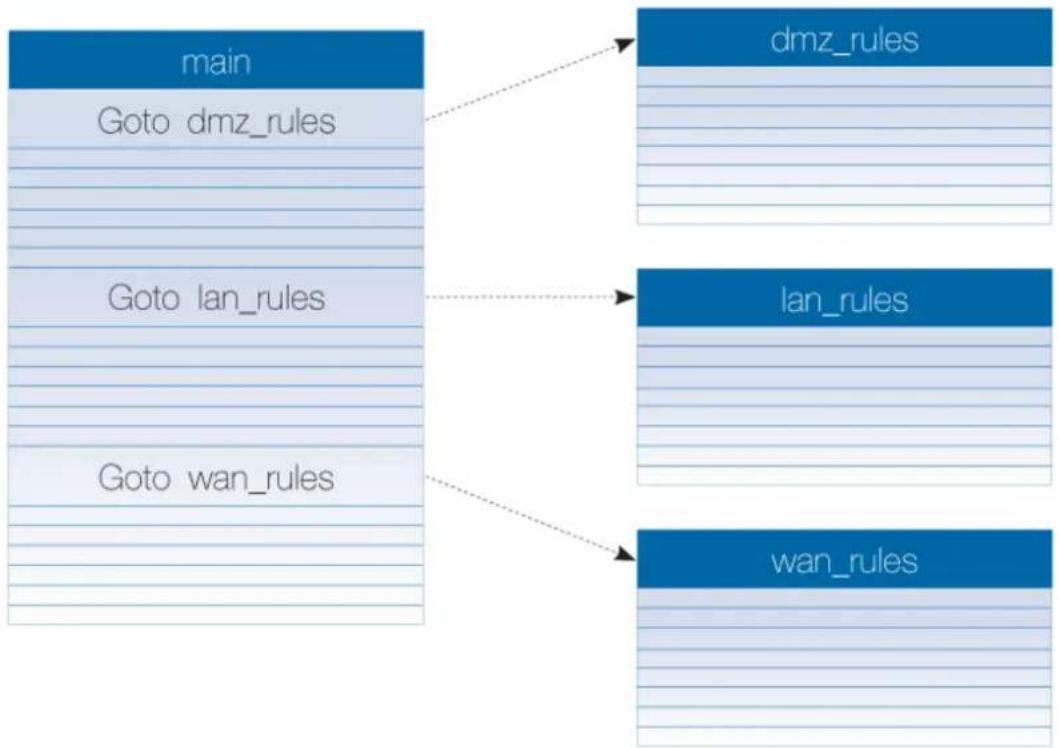
flowchart
graph TD
    A["main"] --> B["dmz_rules"]
    A --> C["Goto dmz_rules"]
    A --> D["Goto lan_rules"]
    A --> E["Goto wan_rules"]
    F["lan_rules"] --> E
    G["wan_rules"] --> E
This example uses the destination network as the method of dividing up the rules but another factor, such as an interface or service, could have been used instead.
This approach creates a multi-level tree structure, a technique which is used in many situations
for efficient searching of large amounts of data. The optimum size of any rule set can only be determined on a case by case basis. However, a rule of thumb that can be applied is to not allow any rule set exceed a thousand entries. Above that number, using Goto rules should be considered to help in speeding up rule set processing.
Example 3.37. Adding a Goto Rule
In this example, a Goto rule is added to the end of the IP rule set main so that all traffic going to the network dmz_net uses the rule set dmz rules. It is assumed that the IP rule set dmz_rules has already been created.
Command-Line Interface
gw-world:/> add GotoRule SourceInterface=any
SourceNetwork=all-nets
DestinationInterface=any
DestinationNetwork=dmz_net
Service=all_services
RuleSet=dmz_rules
Name=goto_dmz
Web Interface
-
Go to: Policies > Firewalling > Add > Goto Rule
-
Now enter:
-
Name: goto_dmz
- RuleSet: dmz_rules
- Source Interface: any
- Source Network: all-nets
- Destination Interface: any
-
Destination Network: dmz_net
• Service: all_services -
Select OK
Adding a Return Rule
As noted earlier, a Return rule cannot be added to the rule set main. It can only be added to an administrator defined IP rule set. Filtering criteria can be added to a Return rule but it is more usual to not specify any traffic type, as shown in the example below. This means that when it is encountered, the Return rule will always return rule set scanning to the entry immediately following the last executed Goto.
Example 3.38. Adding a Return Rule
In this example, a Return rule is added to the end of the administrator defined IP rule set dmz_rules. It will be applicable to all traffic so if it is encountered, processing will return to the rule set entry following the last executed Goto rule.
Command-Line Interface
Change the CLI context to be the rule set:
gw-world:/> cc IPRuleSet dmz_rules
Add the return rule to the rule set:
gw-world:/dmz_rules> add ReturnRule SourceInterface=any
SourceNetwork=all-nets
DestinationInterface=any
DestinationNetwork=all-nets
Service=all_services
Name=return_dmz_to_main
Return to the default CLI context:
gw-world:/main> cc
gw-world:/>
Web Interface
- Go to: Policies > Firewalling > Additional IP Rule Sets
- Select the rule set called dmz_rules
- Select Add > Return Rule
-
Now enter:
-
Name: return_dmz_to_main
- Source Interface: any
• Source Network: all-nets - Destination Interface: any
- Destination Network: all-nets
-
Service: all_services
-
Select OK
3.6.6. IP Rule Set Folders
In order to help organize large numbers of entries in IP rule sets, it is possible to create IP rule set folders. These folders are just like a folder in a computer's file system. They are created with a given name and can then be used to contain all the entries that are related together as a group.
Using folders is simply a way for the administrator to conveniently divide up IP rule set entries and no special properties are given to entries in different folders. NetDefendOS continues to see all entries as though they were a single set of entries.
The folder concept is also used by NetDefendOS in the address book, where related IP address objects can be grouped together in administrator created folders.
3.6.7. Configuration Object Groups
The concept of folders can be used to organize groups of NetDefendOS objects into related collections. These work much like the folders concept found in a computer's file system. Folders are described in relation to the address book in Section 3.1.6, "Address Folders" and can also be used when organizing IP rules.
An alternative to using folders for organizing objects is to use configuration object groups. Object groups allows the administrator to gather together and color code configuration objects under a specified title text so their relationships are more easily understood when they are displayed in a NetDefendOS graphical user interface. Unlike folders, they do not require each folder to be opened for individual objects to become visible. Instead, all objects in all groupings are visible at once.
Object groups can be used not only for address book objects but in most cases where NetDefendOS objects are displayed as tables and each line represents an object instance. The most common usage of this feature is likely to be for either the NetDefendOS Address Book to arrange IP addresses or for organizing rules in IP rule sets.

Tip: Object groups help to document configurations
Object groups are a recommended way to document the contents of NetDefendOS configurations.
This can be very useful for someone seeing a configuration for the first time. In an IP rule set that contains hundreds of rules, object groups provide a means to quickly identify those rules associated with a specific aspect of NetDefendOS operation.
Object Groups and the CLI
The display function of object groups means they do not have relevance to the command line interface (CLI). It is not possible to define or otherwise modify object groups with the CLI and they will not be displayed in CLI output. Any group editing must be done through the Web Interface and this is described next.
A Simple Example
As an example, consider the IP rule set main which contains just two rules to allow web surfing from an internal network and a third Drop-All entry to catch any other traffic so that it can be logged:
| # | Name | Log | Src If | Src Net | Dest If | Dest Net |
| 1 | ▶ lan-to-internet-http | √ | □ lan | □ lannet | □ wan1 | □ all-nets |
| 2 | ▶ lan-to-internet-dns | √ | □ lan | □ lannet | □ wan1 | □ all-nets |
| 3 | ■ drop-all | √ | □ any | □ all-nets | □ any | □ all-nets |

Note
The screen images used in this example show just the first few columns of the object properties.
If it is desirable to create an object group for the two IP rules for web surfing, this is done with the following steps:
- Select the first object to be in the new group by right clicking it.
- Select the New Group option from the context menu.
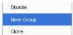
- A group is now created with a title line and the IP rule as its only member. The default title of "(new Group)" is used.
The entire group is also assigned a default color and the group member is also indented. The object inside the group retains the same index number to indicate its position in the whole table. The index is not affected by group membership. The group title line does not have or need an index number since it is only a textual label.
| # | Name | Log | Src If | Src Net | Dest If | Dest Net |
| (New Group) | ||||||
| 1 | ▶ lan-to-internet-http | ✓ | lan | 4 Iannet | wan1 | 4 all-nets |
| 2 | ▶ lan-to-internet-dns | ✓ | lan | 4 Iannet | wan1 | 4 all-nets |
| 3 | ■ drop-all | ✓ | any | 4 all-nets | any | 4 all-nets |
Editing Group Properties
To change the properties of a group, right click the group title line and select the Edit option from the context menu.
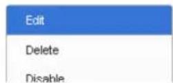
A Group editing dialog will be displayed which allows two functions:
- Specify the Title
The title of the group can be any text that is required and can contain new lines as well as empty lines. There is also no requirement that the group name is unique since it is used purely as a label.
- Change the Display Color
Any color can be chosen for the group. The color can be selected from the 16 predefined color boxes or entered as a hexadecimal RGB value. In addition, when the hexadecimal value box is selected, a full spectrum color palette appears which allows selection by clicking any color in the box with the mouse.
In this example, we might change the name of the group to be Web surfing and also change the group color to green. The resulting group display is shown below:
| # | Name | Log | Src If | Src Net | Dest If | Dest Net |
| Web Surfing | ||||||
| 1 | ▶ lan-to-internet-http | √ | lan | 4 lannet | wan1 | 4 all-nets |
| 2 | ▶ lan-to-internet-dns | √ | lan | 4 lannet | wan1 | 4 all-nets |
| 3 | ■ drop-all | √ | any | 4 all-nets | any | 4 all-nets |
Adding Additional Objects
A new group will always contain just one object. By right clicking the object that immediately follows the group, the Join Preceding option can be selected to add it to the preceding group.
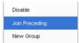
Once we do this for the second IP rule in our example then the result will be the following:
| # | Name | Log | Src If | Src Net | Dest If | Dest Net |
| Web Surfing | ||||||
| 1 | ▶ lan-to-internet-http | √ | lan | 4 lannet | wan1 | 4 all-nets |
| 2 | ▶ lan-to-internet-dns | √ | lan | 4 lannet | wan1 | 4 all-nets |
| 3 | ■ drop-all | √ | any | 4 all-nets | any | 4 all-nets |
To add any object to the group we must first position it immediately following the group and then select the Join Preceding option. This is explained in more detail next.
Adding Preceding Objects
If an object precedes a group or is in any position other than immediately following the group, then this is done in a multi-step process:
i. Right click the object and select the Move to option.
ii. Enter the index of the position immediately following the target group.
iii. After the object has been moved to the new position, right click the object again and select the Join Preceding option.
Moving Group Objects
Once an object, such as an IP rule, is within a group, the context of move operations becomes the group. For example, right clicking a group object and selecting Move to Top will move the object to the top of the group, not the top of the entire table.
Moving Groups
Groups can be moved in the same way as individual objects. By right clicking the group title line, the context menu includes options to move the entire group. For example, the Move to Top option moves the entire group to the top of the table.
Leaving a Group
If an object in a group is right clicked then the context menu contains the option Leave Group. Selecting this removes the object from the group AND moves it down to a position immediately following the group.
Removing a Group
By right clicking on a group title, the displayed context menu includes the Ungroup option. This removes the group, however all the group's member objects remain. The group title line disappears and the individual members appear unindented in the normal ungrouped color. Individual object index positions within the table are not affected.
A group is also removed if there are no members left. If there is only one member of a group, when this leaves the group, the group will no longer exist and the title line will disappear.
Groups and Folders
It is important to distinguish between collecting together objects using a folder and collecting it together using groups.
Either can be used to group objects but a folder is similar to the concept of a folder in a computer's file system. However, a folder cannot be part of a group. Groups collect together related basic objects and a folder is not of this type. It is possible, on the other hand, to use groups within a folder.
It is up to the administrator how to best use these features to best arrange NetDefendOS objects.
3.6.8. Stateless Policy
A Stateless Policy is equivalent to an IP Rule. Both can be used to define a stateless connection, however, using a Stateless Policy is the recommended method.
A stateless connection means that packets pass through the D-Link firewall without a state for the connection being set up in NetDefendOS's state table. Since the stateful inspection process is bypassed, this is less secure than a stateful connection. The traffic processing is also slower since every packet is checked against the entire rule set.
Generally, using a Stateless Policy or IP Rule with a FwdFast action is not recommended because both will yield slower traffic throughput when compared with a normal stateful connection. However, some scenarios with certain protocols might require a stateless connection.
Note that the Protocol property of the Service object used with a Stateless Policy does not need to
be set to anything. The Protocol property is ignored with a Stateless Policy.

Note: By default, logging is enabled for a Stateless Policy
Like other types of policy, logging is enabled by default for a Stateless Policy object. Unfortunately, this means that a log message will be generated for each packet that triggers the rule. This is usually undesirable so it is better to disable logging on the policy.
Example 3.39. Creating a Stateless Policy
In this example, TCP packets will be sent between the internal network lannet and the dmznet network. This might be required in a real world situation because of certain traffic types causing problems.
As with a FwdFast IP rule, two Stateless Policy objects are needed, one for each direction of traffic flow. Instead of creating a custom Service object, this example will use the predefined object all_tcp.
Command-Line Interface
Allow stateless TCP flow from lannet to dmznet:
gw-world:/> add StatelessPolicy SourceInterface=lan
SourceNetwork=lannet
DestinationInterface=dmz
DestinationNetwork=dmznet
Service=all_tcp
Name=stateless_lan_to_dmz
Action=Allow
Allow stateless TCP flow from dmznet to lannet:
gw-world:/> add StatelessPolicy SourceInterface=dmz
SourceNetwork=dmznet
DestinationInterface=lan
DestinationNetwork=dmznet
Service=all_tcp
Name=stateless_dmz_to_lan
Action=Allow
Web Interface
Allow stateless TCP flow from lannet to dmznet:
-
Go to: Policies > Firewalling > Add > Stateless Policy
-
Now enter:
-
Name: stateless_lan_to_dmz
- Action: Allow
- Source Interface: Ian
- Source Network: Iannet
-
Destination Interface: dmz
-
Destination Network: dmznet
- Service: all_tcp
3. Select OK
Allow stateless TCP flow from dmznet to lannet:
-
Go to: Policies > Firewalling > Add > Stateless Policy
-
Now enter:
-
Name: stateless_dmz_to_lan
- Action: Allow
- Source Interface: dmz
• Source Network: dmznet - Destination Interface: Ian
- Destination Network: Iannet
- Service: all_tcp
3. Select OK
3.6.9. Creating IP Rules
An IP Rule can create traffic flow policies which are similar to those created with IP Policy objects. However, they are more complicated to use and are needed only for compatibility with older versions of NetDefendOS.
An IP Rule object consists of two parts:
• The filtering criteria which target the traffic that the rule is aimed at.
• The action that the rule will perform on that traffic.
IP Rule Filters
The filtering parameters of an IP rules are as follows:
- Source Interface.
- Source Network.
- Destination Interface.
- Destination Network.
• Service (this identifies the protocol of the traffic).
The Service in an IP rule can be important because if an Application Layer Gateway object is to be applied to traffic then it must be associated with a service object (see Section 6.1, "ALGs").
IP Rule Actions
When an IP rule is triggered by a match then one of the following Actions can occur:
- Allow
The packet is allowed to pass. As the rule is applied to only the opening of a connection, an entry in the "state table" is made to record that a connection is open. The remaining packets related to this connection will pass through the NetDefendOS "stateful engine".
- FwdFast
Let the packet pass through the firewall without setting up a state for it in the state table. This means that the stateful inspection process is bypassed and is therefore less secure than Allow or NAT rules. Packet processing time is also slower than Allow rules since every packet is checked against the entire rule set.
Instead of using an IP Rule object, the FwdFast functionality can alternatively be configured using a Stateless Policy object. This is described in Section 3.6.8, "Stateless Policy".
• NAT
This functions like an Allow rule, but with dynamic address translation (NAT) enabled (see Section 8.2, "NAT" in Chapter 8, Address Translation for a detailed description).
• SAT
This tells NetDefendOS to perform static address translation. A SAT rule always requires a matching Allow, NAT or FwdFast IP rule further down the rule set (see Section 8.4, "SAT" in Chapter 8, Address Translation for a detailed description).
- Drop
This tells NetDefendOS to immediately discard the packet. This is an "impolite" version of Reject in that no reply is sent back to the sender. It is often preferable since it gives a potential attacker no clues about what happened to their packets.
- Reject
This acts like Drop but will return a TCP RST or ICMP Unreachable message, informing the sending computer that the packet was dropped. This is a "polite" version of the Drop IP rule action.
Reject is useful where applications that send traffic wait for a timeout to occur before realizing that the traffic was dropped. If an explicit reply is sent indicating that the traffic was dropped, the application need not wait for the timeout.
Example 3.40. Creating an Allow IP Rule
This example shows how to create a simple rule that will allow HTTP and HTTPS connections to be opened from the Iannet network on the lan interface to any network (all-nets) on the wan interface.
Command-Line Interface
gw-world:/> add IPRule SourceInterface=lan
SourceNetwork=lannet
DestinationInterface=wan
DestinationNetwork=all-nets
Service=http-all
Action=Allow
Name=lan_http
Web Interface
- Go to: Policies > Firewalling > Main IP Rules > Add > IP Rule
- Specify a suitable name for the rule, for example LAN_HTTP
- Now enter:
• Name: A suitable name for the rule. For example lan_http
• Action: Allow
• Service: http-all
- Source Interface: Ian
- Source Network: Iannet
- Destination Interface: wan
- Destination Network: all-nets
4. Click OK
Note that configuration changes must be saved by issuing the commands activate followed by commit.
Disabling IP Rule Object Usage
It is possible to disable the usage of IP Rule objects (by default, they are enabled). The example below shows how to do this. Disabling IP rule usage does not affect any IP rules that already exists in a configuration. Existing IP rules will continue to perform their intended function and will still appear in IP rule set listing. However, new IP rules can not be created.
Example 3.41. Disabling IP Rule Object Usage
This example will disable the ability to add IP Rule objects to a configuration.
Command-Line Interface
gw-world:/> set Settings MiscSettings AllowIPRules=No
Web Interface
-
Go to: System > Advanced Settings > Misc. Settings
-
Change the following:
- Disable IPRules: Disable
- Click OK
3.7. Application Control
IP policies can be set up so they apply only to traffic related to specific applications. An example of an application that might require this kind of administrator control is traffic related to BitTorrent. Applying IP policies based on the application type is known in NetDefendOS as Application Control.
The application control subsystem is driven using a database of application signatures. Each signature corresponding to one type of application. The entire current signature database is listed in the separate document entitled NetDefendOS Application Control Signatures.
Application control is a subscription based feature and a subscription must have been purchased for application control to function. See Appendix A, Subscribing to Updates for more details about this and for details about the behavior when a subscription expires.
Enabling Application Control
Application Control can be enabled in two ways:
- Specifying applications directly with an IP Policy object.
This is the basic way of either allowing or denying the data flows associated with a given application. This is often used when testing application control since it is simple but does not provide much flexibility.
• Associating an Application Rule Set with an IP Policy object.
This is the recommended method of using application control and provides more flexible ways to handle the data flows associated with applications. An Application Rule Set is first created which defines how an application is to be handled, then one or more Application Rule objects are added to it. The entire rule set is then associated with an IP Policy object.
These two methods of configuring application control are examined next.
Associating Directly with an IP Policy
Using application control directly is configured with the following steps:
- Create an IP Policy with a set of filter parameters to target specific connections.
• Use an Action of Allow and optionally specify NAT source address translation.
- Enable application control in the policy, select the option to use manual configuration and add the applications that are to be allowed or denied.
If the Deny option is selected but no applications are selected then everything is allowed. If the Allow option is selected but no applications are selected then nothing will be allowed.
Example 3.42. Specifying an Application Control Policy
This example creates an IP Policy to deny connections originating from the lan network which match the *_groups signature filter. These will include access to sites such as yahoo_groups and google_groups.
Note that the default source translation of Auto will be used in the IP policy created. This means that connections will automatically be subject to NAT translation when they are from a private IP address to a public address.
Command-Line Interface
First, the appcontrol command must be used to create a list of the applications we are interested in.
gw-world:/> appcontrol -filter -name=*_groups -save_list
This creates a list with an index number of "1".
Next, the created list is used in an IP policy:
gw-world:/> add IPPolicy Name=allow_comp
SourceInterface=lan
SourceNetwork=lannet
DestinationInterface=wan
DestinationNetwork=all-nets
Service=all_services
Action=Allow
AppControl=Yes
AC_AppAction=Deny
AC_Applications=1
Web Interface
-
Go to: Policies > Firewalling > Main IP Rules > Add > IP Policy
-
Now enter:
-
Name: allow_comp
-
Action: Allow
-
Under Filter enter:
-
Source Interface: Ian
- Source Network: Iannet
- Destination Interface: all
-
Destination Network: all-nets
• Service: all_services -
Under Application Control enter:
-
Application Control: Enable
• Use Manual Configuration: Enable - Application Action: Deny
-
Using the Add button, select yahoo_groups and google_groups from the application definitions.
-
Click OK
Using an Application Rule Set
As described previously, another, recommended way of controlling applications is to create an Application Rule Set object and associate this with an IP Rule or IP Policy object.
An Application Rule Set object will contain one or more Application Rule objects as children and these define an application and what actions are to be taken when the application is recognized by NetDefendOS.
An application rule set has a Default Action property which has a value of either Allow or Deny. If the action is set to Allow, everything is allowed unless it is specifically denied by a rule. If set to Deny, everything is denied unless it is specifically allowed by a rule.
Using application rule sets allows not only data for a certain application to be allowed or denied but also the following additional controls:
- Authentication Settings
For an Allow application rule, the requesting client is only permitted the connection if they have already been authenticated by NetDefendOS and are also one of any usernames specified in that application rule or belong to one of the groups specified in the rule. In addition, the specified group or username should also be specified for the source network address object used with the associated IP rule or policy and this is explained further later in this section.
For a Deny rule, the requesting client is denied the connection if they are authenticated and are one of the usernames specified or belong to one of the specified groups.
Authentication may have performed using any of the methods available in NetDefendOS Authentication Rule objects, including Identity Awareness.
If no groups or usernames are specified in an Application Rule object, authentication is ignored.
- Traffic Shaping Settings
Predefined NetDefendOS Pipe objects can be associated with the rule so the bandwidth limit specified by pipe objects can be placed on the either direction of data flow or both.
This feature therefore allows bandwidth limits to be placed on a given application and, if used in conjunction with the authentication setting, on particular users or user groups using that application.
Traffic shaping is only relevant if the Application Control Rule has an action of Allow.
Applying Application Control to Specific Groups or Usernames
Sometimes, application control will need to be applied to a specific group of users or specific individual users. This can be achieved by doing the following:
- Specify a list of the specific groups and/or usernames for the Authentication Settings property of the relevant Application Rule object.
- The Source Network property of the associated IP Rule or IP Policymust be set to an address book IP object for which either of the following is true:
i. The address object has the property No defined credentials enabled.
ii. The address object has the same groups and/or usernames as the Application Rule
defined for its User Auth Groups property.
Example 3.43. Using an Application Control Rule Set
This example will limit the usage by the user group called rogue_users to 0.25 Megabit of bandwidth for both uploading and downloading of data using BitTorrent. Assume the following:
- Membership of a user in a group called rogue_users is established by the authentication process. This might be done by using a RADIUS server or using other means such as authenticating against an LDAP server. The means of authentication is not discussed further.
- A Pipe object called narrow_025_pipe has already been defined in NetDefendOS that permits this data flow.
- An IP Policy object called lan_to_wan_policy has already been defined that allows connections from a protected internal network to the Internet.
- The Source Network property for the lan_to_wan_policy IP policy is already set to an IPv4 address book object called lan_users_net.
It is assumed that all clients on the local network that access the Internet must be authenticated.
Command-Line Interface
First, the appcontrol command is used to create a filter for BitTorrent. This should also include the uTP protocol:
gw-world:/> appcontrol -filter -application=bittorrent,utp -save_list
Assume that this filter list is the third filter list created and is therefore assigned the list number 3. All filters can be displayed with the command:
gw-world:/> appcontrol -show_lists
Next, create an ApplicationRuleSet called bt_app_list:
gw-world:/> add Policy ApplicationRuleSet bt_app_list
DefaultAction=Allow
Then, change the CLI context to be bt_app_list:
gw-world:/> cc Policy ApplicationRuleSet bt_app_list
gw-world:/bt_app_list>
Now, add the ApplicationRule object:
gw-world:/bt_app_list> add ApplicationRule
Action=Allow
AppFilter=3
UserAuthGroups=rogue_users
ForwardChain=narrow_025_pipe
ReturnChain=narrow_025_pipe
Then, return to the default context:
gw-world:/bt_app_list> cc
gw-world:/>
Associate this ApplicationRuleSet with the IPPolicy:
gw-world:/> set IPPolicy lan_to_wan_policy
    AppControl=Yes
    AC_RuleSet=bt_app_list
Finally, set the source network address object of lan_to_wan_policy so it has the same group name as the application rule:
gw-world:/> set Address IP4Address lan_users_net UserAuthGroups=rogue_users
Note that the following would also allow application control to function:
gw-world:/> set Address IP4Address lan_users_net NoDefinedCredentials=Yes
Web Interface
First, define the Application Rule Set:
- Go to: Policies > Firewalling > Application Rule Sets > Add > Application Rule Set
- Specify a suitable name for the list, in this case bt_app_list
- Set the Default Action to Allow
- Click OK
Next, define an Application Rule as a child.
- Go to: Policies > Firewalling > Application Rule Sets > bt_app_list > Add > Application Rule
- Select Allow for the Action
- Enable Application Control and add the signatures bittorrent and utp (both are required for BitTorrent).
- Select Authentication Settings and enter the group name rogue_users
- Select Traffic Shaping Settings and move the pipe narrow_025_pipe into the Selected list for both the Forward chain and Return chain
- Click OK
Associate the Application Rule Set with the IP Policy:
- Go to: Policies > Firewalling > Main IP Rules > Ian_to_wan_policy
- Under Application Control enter:
- Enable Application Control: Enabled
• Application Rule Set: bt_app_list
3. Click OK
Finally, set the source network address object of lan_to_wan_policy so it has the same authentication group name as the application rule.
- Go to: Objects > Address Book > Add > IP4 Address
- Select lan_to_wan_policy
- In User Auth Groups enter rogue_users
- Click OK
Note that enabling No defined credentials in lan_to_wan_policy would also allow application control to function.

Tip: BitTorrent signatures should include uTP
As seen in the above example, when application control is configured to target BitTorrent, the two signatures bittorrent and utp should both be selected.
The Strict HTTP Setting
Many protocols that application control examines are built on top of the HTTP protocol. In some cases where HTTP itself is being blocked by application control, a protocol built on HTTP may be erroneously blocked as well. To try to resolve this problem, the Strict HTTP setting can be disabled for the relevant Application Rule Set object. This will force application control to evaluate the entire protocol structure before making a decision on the protocol type.
Changing the Maximum Unclassified Packets
The NetDefendOS application control subsystem processes a connection's data flow until it decides if a connection is unclassifiable or not. The maximum amount of data processed to make this decision is specified in NetDefendOS as both a number of packets and a number of bytes. By default, these two values are:
• Maximum Unclassifiable Packets: 5
• Maximum Unclassifiable Bytes: 7500
When either of these values is reached, the unclassifiable decision is made. If the administrator needs to increase the maximum amount of data processed because some protocols are being incorrectly flagged as unclassifiable, then the values can be changed in one of two ways:
• They can be changed globally in the NetDefendOS Advanced Settings.
- The current global settings can be overridden for all rules in a rule set by selecting the Use Custom Limits option for an Application Rule Set object.
Application Content Control
So far, application control has been described in terms of targeting specific applications such as BitTorrent or Facebook™. However, NetDefendOS allows a further level of filtering within application control where the content of targeted applications decide if the traffic will be allowed, blocked or just logged. This feature is called Application Content Control.

Note: Application Content Control is not CLI configurable
The ability to configure application content control is not available in the CLI. Only the Web Interface can be used to configure this feature.
Application content control is configured on application rule objects within an application rule set. Application content control can be used to target specific content within a targeted application. Facebook™ provides a good example of how this can be applied. The rule can target Facebook and then application content can be used to target types of Facebook content such as specific games, applications, chat or messages.
If there are multiple IP policies in a rule set that are using deep content control, then all policies may need to perform the same filtering since a higher policy in the rule set might trigger before a lower one. For example, if only the Chrome browser is being allowed, all IP policies using application content control should test if the HTTP user-agent is Chrome.
Example 3.44. Application Content Control
This example shows how only the Chrome and Firefox browsers only will be allowed by an application rule using application content control.
Associating the application rule set created together with an IP policy will not be included in the example but follows the same steps shown in the previous example.
Web Interface
First, define the Application Rule Set:
- Go to: Policies > Firewalling > Application Rule Sets > Add > Application Rule Set
- Specify a suitable name for the list, in this case browser_list
- Set the Default Action to Allow
- Click OK
Next, define an Application Rule in this rule set:
- Go to: Policies > Firewalling > Application Rule Sets > browser_list > Add > Application Rule
- Select Allow for the Action
- Under Application Filter press Select filter.
- In the Search field enter http
-
Select Matches specific applications
-
Open the Web node and select http from the list of matching applications
- Press the Select button to close the filter dialog
Define an Application Content filter:
- Select the Content Control tab
- Set User Agent to Allow Selected
- In the blank text field type firefox followed by enter and the chrome followed by enter.
- Click OK
Lastly, associate this Application Rule Set with the appropriate IP Policy that triggers on the relevant traffic as shown in an earlier example.
As explained previously, the policy and therefore this rule set will only trigger if no previous rule has triggered for the same traffic.

Note: String matches are a subset and case insensitive
When specifying string matches for application content control, the matching function is case insensitive and always a subset function. In the example above, the string firefox is specified for the user_agent property and this will trigger on any version of Firefox since the agent field always contains this string.
Extended Logging
When using application content control, it is possible to enable logging for different content. This means that special log messages will be generated by NetDefendOS when the rule triggers on a configured piece of content.
For example, if the user_agent in application content has logging enabled and the Allow Selected string is set to firefox, this will allow the Firefox browser to be used and also generate a log message to indicate that Firefox caused the rule to trigger. The string firefox will be included in the log message.
The log messages generated by extended logging in application control will always be one of the following events:
- application_content_allowed
- application_content_denied
- application_content
(The action was Ignore but logging is Yes.)
Example 3.45. Application Content Control with Logging
This example shows how access to Facebook ^™ can be allowed but the Facebook chat function disallowed using application content control. A log event will also be generated every time a
user tries to use the chat function.
Associating the application rule set created together with an IP policy will not be included in the example but follows the same steps shown in the previous example.
Web Interface
First, define the Application Rule Set:
- Go to: Policies > Firewalling > Application Rule Sets > Add > Application Rule Set
- Specify a suitable name for the list, in this case facebook_list
- Set the Default Action to Allow
- Click OK
Next, define an Application Rule in this rule set:
- Go to: Policies > Firewalling > Application Rule Sets > facebook_list > Add > Application Rule
- Select Allow for the Action
- Under Application Filter press Select filter to open the filter dialog
- Under Tag select Social Networking
- Choose Matches specific applications
- Open the Web node and choose Facebook
- Press the Select button to close the filter dialog
Define an Application Content filter:
- Select the Content Control tab
- For Chat set Action to be Deny and Log to be Log
- Click OK
Lastly, associate this Application Rule Set with the appropriate IP Policy that triggers on the relevant traffic as shown in an earlier example.
Data Leakage Can Occur
Application control functions by analyzing sequential streams of packets and a certain number of packets must be processed using signatures before a determination can be made as to which application it is.
This means that it is inevitable that not all the packets belonging to a targeted application can be caught and some data leakage will occur where some blocked traffic will arrive at its destination. However, when using IP rules or IP policies only, every packet of the triggering connection will
be blocked and there is no data leakage.
Browsing the Application Control Database
In the CLI, the command appcontrol can be used to examine the application control database of application definitions. Without any parameters, this command shows the database size. For example:
gw-world:/> appcontrol
Application library contents:
842 application definitions.
34 families.
4 tags.
If tab completion is used after the command, all the definition families are displayed. For example:
gw-world:/> appcontrol <tab>
antivirus/ file_transfer/ network_management/ thin_client/
application_service/ forum/ network_service/ tunneling/
audio_video/ game/ peer_to_peer/ unclassified/
authentication/ instant_messaging/ printer/ wap/
compression/ mail/ qosmos/ web/
database/ messenger/ routing/ webmail/
encrypted/ microsoft_office/ security_service/
erp/ middleware/ telephony/
file_server/ music_player/ terminal/
These families consist of the individual definitions. For example, to view the two definitions in the compression family, use the command:
gw-world:/> appcontrol compression
compression - Compression:
ccp
comp
2 application(s)
To view a single definition, the individual name can be used without the family. For example, to display the comp definition within the compression family:
gw-world:/> appcontrol comp
comp - Compression
COMP protocol is used for data compression over PPP.
Family: Compression
Risk Level: 1 - Very low risk
Tags:
Revision: 0
Enabled: Yes
The Tags and Risk Level add further information to each definition but are not part of the definition hierarchy. The Risk Level indicates the degree of threat that this particular application poses. The Tags provide more information about the data traffic related to the application, for example High Bandwidth might be a typical tag.
It is possible to search the definition database by using any of the filter parameters:
- name
- family
-
name
-
risk
- tag
The name parameter must always be the first in a search but the asterisk "*" character can be used as a wildcard. For example:
gw-world:/> appcontrol -name=* -family=mail -risk=HIGH
As demonstrated earlier, the -save_list option is used to save a filter list so it can be used with IP rules and IP policies.
Managing Filters
As shown in the application example above for controlling BitTorrent, the appcontrol CLI command is also used to create saved filters which are then used with the CLI in ApplicationRule objects. For example, the following will create a saved filter for BitTorrent:
gw-world:/> appcontrol -filter -application=bittorrent,utp -save_list
The -application parameter specifies the individual signatures by name. An alternative is to use the -name parameter which allows wildcarding and searches the signatures names looking for character pattern matches. For example, we could have specified:
gw-world:/> appcontrol -filter -name=bit* -save_list
All the signatures with names that begin with the prefix bit would have been selected. It would not have been possible to select bittorrent and utp using the -name parameter.
All the saved filters can be displayed with the command:
gw-world:/> appcontrol -filter -show_lists
To delete all saved filters, use the command: All the saved filters can be deleted with the command:
gw-world:/> appcontrol-delete_lists=all
Individual saved filters can be deleted by specifying the number of the filter after -delete_lists=.
Selecting All Signatures
If the administrators aim is to find out what applications users are accessing, application control can be used to do this by triggering on all signatures and allowing instead of blocking the traffic. The log events generated will indicate the applications that are being detected.
Selecting all signatures is done through a checkbox in the Web Interface and can be done with the CLI by using wildcarding with an ApplicationRuleSet object. The CLI cannot be used when using application control directly with IP rules.
Signature Inheritance
The application control signatures have a hierarchical structure and it is important to remember that permissions are also inherited. An example of this is the http signature. If the administrator configures application control to block all http traffic they are also blocking all applications that use http such as facebook and dropbox.
However, if the administrator configures application control to allow the http signature they are also allowing all applications that use http. For instance, the signature for DropBox is a child of
the http signature so allowing http traffic also allows dropbox traffic. If dropbox is to be blocked while still allowing http, it must be blocked separately.
Risk Guidelines
The following are guidelines for how the risk parameter for each application control signature should be viewed by the administrator:
- Risk Level 5
Very high risk. This traffic should be blocked unless special circumstances or requirements exist. For example, PHP-, CGI-, HTTPS-proxies; known attack sites.
- Risk Level 4
High risk. This traffic should be reviewed and a block or allow action taken. Site-to-site tunneling should be used where possible. For example, SSH, LDAP, RADIUS, Dropbox and similar.
- Risk Level 3
Medium risk. Signatures with this risk level can affect network security, bandwidth usage and company integrity if care is not taken. For example, Facebook and other social networks, Google Analytics and similar aggregators, P2P/filesharing
- Risk Level 2
Moderate risk. Signatures with this risk level can affect network security and/or affect bandwidth usage. For example, video streaming sites, Java/Flash game sites
- Risk Level 1
Low-risk. Signatures that could be candidates for blocking. Typically not a threat. For example, E-commerce sites, news portals.
Application Control Subscription Expiry
As mentioned previously, application control requires a subscription to be purchased for the feature to function.
If the subscription expires, the following will happen if application control has been configured on any IP Policy objects:
- A console message is generated at system startup or on reconfiguration to indicate subscription expiry.
- Application control will continue to function so that traffic continues to flow through NetDefendOS but, whenever it triggers, the data type will be set to Unknown.
For example, if the administrator had configured BitTorrent traffic to be dropped, it will no longer be dropped because it has been recognized and then reclassified as Unknown traffic.
- Whenever application control triggers, the log message application_identified will be generated as usual but the traffic type will be marked as Unknown. Similarly, the type Unknown will also appear in the application_end log message.
- In addition, the log message application_control_disabled will also be generated when application control triggers.
The current status of the application control subscription can be viewed with the Web Interface by going to Status > Maintenance > License.
3.8. Schedules
It can be sometimes useful to control not only what functionality is enabled, but also when that functionality can be used.
For instance, an enterprise might require that web traffic from a certain department is only allowed Internet access during normal office hours. Another example might be that authentication using a specific VPN connection is only permitted on weekdays.
NetDefendOS addresses this time-based requirement using either of the following types of configuration objects:
- Schedule Profile objects - These provide a simple scheduling capability.
- Advanced Schedule Profile objects - These provide more advanced scheduling.
Either of these object types can be created and then assigned to the Schedule property of many different types of configuration objects, including IP rule set entries, traffic shaping rules, IDP rules and routing rules. The assigned schedule then determines when the object is enabled and when it is disabled.

Important: The system date and time should be correct
As schedules depend on an accurate system date and time so it is important that this is set correctly. This can also be important for some other NetDefendOS features such as certificate usage with VPN tunnels.
It is recommended that the automatic time synchronization feature in NetDefendOS is enabled to ensure the system time is set correctly. This is discussed further in Section 2.2, "System Date and Time".
Schedule Profiles
The Schedule Profile object provides the simplest form of scheduling. Multiple times can be specified for each day of the week and a start and a stop date can also be specified.
A Schedule Profile object has the following properties:
- Name
The name of the schedule. This is used in user interface display and as a reference to the schedule from other objects.
- Scheduled Times
These are the times during each week when the schedule is applied. Times are specified as being to the nearest hour. A schedule is either active or inactive during each hour of each day of a week.
- Start Date
If this option is used, it is the date after which this schedule object becomes active. If not specified, the schedule will apply as soon as it is assigned to an object.
• End Date
If this option is used, it is the date after which this schedule object is no longer active. If not
specified there will be no end date for the schedule
Example 3.46. Setting up a Schedule Profile with an IP Policy
This example creates a Schedule Profile object for office hours (08:00 to 17:00) on weekdays and uses it with a NATing IP Policy that allows HTTP and HTTPS traffic to flow from internal clients to the Internet. The schedule will begin to apply on the 24th of December, 2018 so the IP policy will not be active before that date.
Command-Line Interface
gw-world:/> add ScheduleProfile my_basic_schedule
Mon=8-17 Tue=8-17 Wed=8-17 Thu=8-17 Fri=8-17
StartDate=2018-12-24
Create the IP policy that uses this schedule:
gw-world:/> add IPPolicy Name=my_client_access_policy
SourceInterface=lan
SourceNetwork=lannet
DestinationInterface=any
DestinationNetwork=all-nets
Service=http-all
Action=Allow
SourceAddressTranslation=NAT
NATSourceAddressAction=OutgoingInterfaceIP
Schedule=my_basic_schedule
Web Interface
-
Go to: Policies > Firewalling > Schedules > Add > Schedule Profile
-
Enter the following:
- Name: my_basic_schedule
-
Select 08-17, Monday to Friday in the grid
-
For Start Date enter 2018-12-24
-
Click OK
Create the IP policy that uses this schedule:
-
Go to: Policies > Firewalling > Main IP Rules > Add > IP Policy
-
Now enter:
• Name: my_client_access_policy
- Action: Allow
- Under Filter enter:
- SourceInterface: Ian
- SourceNetwork lannet
- DestinationInterface: any
- DestinationNetwork: all-nets
• Service: http -
Schedule: my_basic_schedule
-
Under Source Translation enter:
-
Address Translation: NAT
• Address Action: Outgoing Interface IP -
Click OK
Advanced Schedule Profiles
The Advanced Schedule Profile object extends the idea of the more basic Schedule Profile object by allowing multiple Advanced Schedule Occurrence objects to be added to it as children.
This provides the ability to create a more complex schedule when compared to the Schedule Profile object. For example, the Advanced Schedule Profile makes it possible to chain together multiple days without interruptions. It also allows schedules to be constructed based on months rather than just days of the week.
The Advanced Schedule Profile has no other properties apart from the Name and Comments properties. The Advance Schedule Occurrence objects added as children have the following properties:
- Start Time
Start time specified in hours and minutes during the day when the occurrence begins.
- End Time
End time specified in hours and minutes during the day when the occurrence begins. This must be specified.
• Occurrence
The type of occurrence. This can be set to Weekly (the default) or Monthly.
• Weekly
If the Occurrence property is set to Weekly, this property is set to the days in the week when the occurrence will apply.
• Monthly
If the Occurrence property is set to Monthly, this property is set to the months in the year when the occurrence will apply.
Example 3.47. Setting up an Advanced Schedule Profile with an IP Policy
This example creates an Advanced Schedule Profile object that is used with a NATing IP Policy that allows HTTP and HTTPS traffic to flow from internal clients to the Internet during 7:15 to 17:45 from monday to friday and during 11:30 to 16:15 on saturday and sunday.
Command-Line Interface
gw-world:/> add AdvancedScheduleProfile my_adv_schedule
gw-world:/> cc AdvancedScheduleProfile my_adv_schedule
gw-world:/my_adv_schedule> add AdvancedScheduleOccurrence
StartTime=7:15
EndTime=17:45
Occurrence=Weekly
Weekly=1-5
Add the second occurrence:
gw-world:/my_adv_schedule> add AdvancedScheduleOccurence
    StartTime=11:30
    EndTime=16:15
    Occurrence=Weekly
    Weekly=6-7
gw-world:/my_adv_schedule> cc
gw-world:/>
Create the IP policy that uses this schedule:
gw-world:/> add IPPolicy Name=http_during_office_hour
SourceInterface=lan
SourceNetwork=lannet
DestinationInterface=any
DestinationNetwork=all-nets
Service=http-all
Action=Allow
SourceAddressTranslation=NAT
NATSourceAddressAction=OutgoingInterfaceIP
Schedule=my_adv_schedule
Web Interface
-
Go to: Policies > Firewalling > Schedules > Add > Schedule Profile
-
Enter the following:
- Name: my_adv_schedule
-
Select the Occurrences tab
-
Select Add > Advanced Schedule Occurrence
-
Enter the following:
- Start Time: 7:15
• End Time: 17:45
• Occurrence: Weekly
• Enable days Monday to Friday
- Click OK to close the occurrence
Add the second occurrence:
-
Select Add > Advanced Schedule Occurrence
-
Enter the following:
-
Start Time: 11:30
-
End Time: 16:15
• Occurrence: Weekly
• Enable days Saturday and Friday -
Click OK to close the occurrence
-
Click OK to close the schedule
Create the IP policy that uses this schedule:
- Go to: Policies > Firewalling > Main IP Rules > Add > IP Policy
- Now enter:
• Name: http_during_office_hours
• Action: Allow
-
Under Filter enter:
-
SourceInterface: Ian
- SourceNetwork Iannet
- DestinationInterface: any
- DestinationNetwork: all-nets
• Service: http -
Schedule: my_adv_schedule
-
Under Source Translation enter:
-
Address Translation: NAT
• Address Action: Outgoing Interface IP -
Click OK
3.9. Certificates
3.9.1. Overview
The X.509 Standard
NetDefendOS supports digital certificates that comply with the ITU-T X.509 standard. This involves the use of an X.509 certificate hierarchy with public-key cryptography to accomplish key distribution and entity authentication. References in this document to certificates mean X.509 certificates.
When distributed to another party, a certificate performs two functions:
• It distributes the certificate owner's public key.
• It establishes the certificate owner's identity.
A certificate acts as a digital proof of identity. It links an identity to a public key in order to establish whether a public key truly belongs to the supposed owner. By doing this, it prevents data transfer interception by a malicious third-party who might post a fake key with the name and user ID of an intended recipient.
Certificate Components
A certificate consists of the following:
• A public key.
• The "identity" of the user, such as name and user ID.
- Digital signatures that verify that the information enclosed in the certificate has been verified by a CA.
By binding the above information together, a certificate is a public key with identification attached, coupled with a stamp of approval by a trusted party.
Certificates in NetDefendOS
A certificate is stored in a NetDefendOS configuration as a Certificate object. There is always one certificate object already predefined in NetDefendOS which is the self-signed certificate HTTPSAdminCert and this is sent to the browser when opening a Web Interface session using HTTPS and is also used with SSL VPN.
A list of installed certificates can be displayed with the Web Interface or CLI. With the CLI, the command would be:
gw-world:/> show Certificate
Name Type Comments
HTTPSAdminCert Local <empty>
The HTTPSAdminCert is a pre-installed certificate in NetDefendOS that is used for management communication using HTTPS. This certificate is "self-signed". To view the properties of this certificate, use the CLI command:
gw-world:/> show Certificate HTTPSAdminCert
Property Value Remarks
Name: HTTPSAdminCert
Type: Local
CertificateData: (binary data)
PrivateKey: (binary data)
CRLChecks: Enforced
CRLDistPointList: <empty>
PKAType: RSA Read-only
IsCA: No Read-only
Attribute: <empty>
Comments: <empty>

Note: Certificates objects cannot be added using the CLI
The Add command is not used to create a certificate object in the CLI. Instead, certificate files are uploaded directly using SCP and the upload creates the object directly. Alternatively, the files can be uploaded using the Web Interface.
Certificate Object Properties
The key properties of a Certificate object are the following:
- Type
The Type property of a Certificate object can take one of the following values:
i. Local
This is the type for most certificates and means both the public key and the private key of the certificate is stored on the firewall.
Local certificates can be signed or unsigned. They always consist of two files. A public key file with the filetype .cer and a private key file with the filetype .key.
ii. Remote
This is the type for remote certificates which have the public key file residing locally in NetDefendOS and the private key file present on a CA server. Often, the certificate is a CA signed root certificate used to validate other certificates.
These certificates consist of just a single public key file with a filetype of .cer.
iii. Request
This type is not currently used by NetDefendOS.
• CRL Checks
The CRL Checks property of a Certificate object determines if the CRL for the certificate is to be checked by NetDefendOS and what happens if the CRL cannot be retrieved to do the checking. The possible values for this property are the following:
i. Enforced
This is the default and means that the associated CRL must be checked before the certificate can be used for authentication. If the associated CRL cannot be retrieved,
perhaps because a CA server is offline, then the certificate will be unusable and authentication will fail.
If the certificate has no CRL associated with it then enforced checking is ignored. A self-signed certificate, such as the ones used for NetDefendOS management connections, do not have an associated CRL but will still have this default option selected.
ii. Conditional
CRL checking will be performed by NetDefendOS provided any associated CRL is available. If the CRL cannot be accessed, perhaps because a CA server is offline, then the certificate will be used anyway.
iii. Disabled
The causes all CRL checking to be disabled. The certificate will be used even if there is a CRL associated with it.
CRLs are discussed further later in this section.
• CRL Distribution Point List
The CRL Distribution Point List property of a Certificate object can be set to a CRL Distribution Point List configuration object defined by the administrator. This can provide alternative means to perform CRL checking if it is enabled. This feature is described further in Section 3.9.3, "CRL Distribution Point Lists".
Creating Certificates Objects in NetDefendOS
A Certificate configuration object is used for defining a logical certificate in NetDefendOS. When such an object is added, it acts as a holder for associated certificate files. Certificate files are associated with a certificate object in one of two ways:
- Importing External Certificate Files
Certificate files stored on the management workstation's local hard disk are imported into NetDefendOS.
- Creating a Self-signed Certificate
The Web Interface can be used to get NetDefendOS to create the required files for a self-signed certificate (the key length is fixed at 2048 bits). To do this, go to Objects > Key Ring > Add > Certificate in the Web Interface and choose Generate (RSA) from the Source options for the new certificate. This allows the following properties to be specified for the self-signed certificate:
i. Common Name.
ii. Certification Authority.
If the Certification Authority is enabled, this means that the self-signed certificate can be used to sign other certificates and act as a CA root certificate.
Certificates with VPN Tunnels
The main usage of certificates in NetDefendOS is with VPN tunnels. The simplest and fastest way to provide security between the ends of a tunnel is to use Pre-shared Keys (PSKs). As a VPN network grows, so does the complexity of using PSKs. Certificates provide a means to better manage security in much larger networks.
Certificate Authorities
A certificate authority (CA) is a trusted entity that issues certificates to other entities. The CA digitally signs all certificates it issues. A valid CA signature in a certificate verifies the identity of the certificate holder, and guarantees that the certificate has not been tampered with by any third party.
A CA is responsible for making sure that the information in every certificate it issues is correct. It also has to make sure that the identity of the certificate matches the identity of the certificate holder.
Root Certificates and Host Certificates
If a certificate is used for authentication, then it can be referred to as a Host Certificate but is sometimes referred to in NetDefendOS as a Gateway Certificate. The certificate will consist physically of two files, a .cer file containing the public key and a .key file containing the private key. Both files must be loaded into NetDefendOS.
If the host certificate is CA signed then the Root Certificate provided by the signing CA will also need to be loaded into NetDefendOS. This is just a single .cer file containing the public key of the CA. Self-signed certificates will not have a corresponding root certificate.
Certificate Chains
A CA can also issue certificates to other CAs. This can lead to a chain-like certificate hierarchy. Each certificate in the chain is signed by the CA of the certificate directly above it in the chain. The certificates between the root and host certificates are called Intermediate Certificates and consist physically of a single .cer file containing a public key.
The Certification Path refers to the path of certificates leading from one certificate to another. When verifying the validity of a host certificate, the entire path from the host certificate up to the trusted root certificate has to be available. For this reason, all intermediate certificates between the root certificate and the host certificate must be loaded into NetDefendOS.
Chained certificates are supported in the following NetDefendOS features:
- Access with HTTPS to the Web Interface.
- IPsec VPN.
- SSL VPN.
• The TLS ALG.
In NetDefendOS IPsec VPN, the maximum length of a certificate chain is 4. In VPN scenarios with roaming clients, the client's certificate will be the bottom of the certificate chain.
Validity Time
A certificate is not valid forever. Each certificate contains values for two points in time between which the certificate is valid. When this validity period expires, the certificate can no longer be used and a new certificate must be issued.

Important: The system date and time must be correct
Make sure the NetDefendOS system date and time are set correctly when using certificates. Problems with certificates, for example in VPN tunnel establishment, can be due to an incorrect system date or time.
The NetDefendOS Certificate Cache
NetDefendOS maintains a Certificate Cache in local memory which provides processing speed enhancement when certificates are being repeatedly accessed. This cache is only completely cleared and initialized when NetDefendOS is restarted.
For this reason, it is important to restart NetDefendOS if any certificates are added, modified or deleted. This can be done with the CLI command:
Certificate Revocation Lists (CRLs)
A Certificate Revocation List (CRL) contains a list of all certificates that have been canceled before their expiration date. They are normally held on an external server which is accessed to determine if the certificate is still valid. The CRL is downloaded from the server and NetDefendOS performs the validation of the certificate against the list. The ability to validate a user certificate in this way is a key reason why certificate security simplifies the administration of large user communities.
CRLs are published on servers that all certificate users can access, using either the LDAP or HTTP protocols. Revocation can happen for several reasons. One reason could be that the keys of the certificate have been compromised in some way, or perhaps that the owner of the certificate has lost the rights to authenticate using that certificate, perhaps because they have left the company. Whatever the reason, server CRLs can be updated to change the validity of one or many certificates.
Certificates will usually contain a CRL Distribution Point (CDP) field, which specifies one or more URLs with which the relevant CRL can be downloaded. In some cases, a certificate may not contain this field and the location of the CRL has to be configured manually. In NetDefendOS this is done by specifying a CRL Distribution Point List object and associating this with the certificate in the configuration. This is explained further in Section 3.9.3, "CRL Distribution Point Lists".
A CA usually updates its CRL at a given interval. The length of this interval depends on how the CA is configured. Typically, this is somewhere between an hour to several days.
For NetDefendOS to check the CRL for a given certificate it may need access to an external CA server. Allowing this access is discussed in detail in Section 3.9.4, "CA Server Access".
Trusting Certificates
When using certificates, NetDefendOS will trust a party whose certificate is signed by a given CA. Before a certificate is accepted, the following steps are taken to verify the validity of the certificate:
- Construct a certification path up to the trusted root CA.
- Verify the signatures of all certificates in the certification path.
- Fetch the CRL for each certificate to verify that none of the certificates have been revoked.
ID Lists
In addition to verifying the signatures of certificates, NetDefendOS can also use an ID list object when authenticating a connecting IPsec client. An ID list contains all IDs that are allowed access through a specific IPsec tunnel. An ID is sent by the peer during the IKE negotiation and if a matching tunnel is found with this remote ID, authentication is then performed by checking to see if the certificate sent by the client contains that ID.
Using IPsec ID lists with certificates is described further in Section 10.3.18, "Using ID Lists with Certificates".
Reusing Root Certificates
In NetDefendOS, root certificates should be seen as global entities that can be reused between VPN tunnels. Even though a root certificate is associated with one VPN tunnel in NetDefendOS, it can still be reused with any number of other, different VPN tunnels.
Other Considerations
A number of other factors should be kept in mind when using certificates:
- If Certificate Revocation Lists (CRLs) are used then the CRL distribution point is defined as an FQDN (for example, caserver.example.com) which must be resolved to an IP address using a public DNS server. At least one DNS server that can resolve this FQDN should therefore be defined in NetDefendOS.
The CRL distribution point can be contained in the certificate but NetDefendOS provides the ability to associate alternative CRL distribution points a certificate. This is described further in Section 3.9.3, "CRL Distribution Point Lists".
- Do not get the Host Certificate files and Root Certificate files mixed up. Although it is not possible to use a Host Certificate in NetDefendOS as a Root Certificate, it is possible to accidentally use a Host Certificate as a Root Certificate.
- Host certificates have two files associated with them and these have the filetypes .key file and .cer. The filename of these files must be the same for NetDefendOS to be able to use them. For example, if the certificate is called my_cert then the files my_cert.key and my_cert.cer.
3.9.2. Uploading and Using Certificates
Certificate File Uploading
Certificate files can be uploaded to NetDefendOS in one of two ways:
- Upload using Secure Copy (SCP).
- Upload through the Web Interface.
SCP Uploading
The following command lines show how a typical SCP utility might upload a certificate consisting
of the two files called cert-1.cer and cert-1.key to a firewall which has the management IP address 192.168.3.1:
scp C:\cert-1.cer admin@192.168.3.1:certificate/my_cert
scp C:\cert-1.key admin@192.168.3.1:certificate/my_cert
The certificate object name in NetDefendOS is my_cert for the certificate and this is how it is referenced by other objects in the configuration.
All certificate uploads should be followed by the configuration being activated since it has been changed with new objects.
Graphical Interface Uploading
This example covers importing certificate files with the Web Interface.
As mentioned earlier, there can be one or two files to upload depending on the certificate type:
- Local Certificates
These certificates consist of both a public key .cer file and a private key file with the filetype .key.
- Remote Certificates
A Remote Certificate is issued by a CA authority and consists of just a single file with a filetype of .cer and this is the public key. The private key is kept on the CA server. The NetDefendOS upload procedure consists of uploading this one file.
Example 3.48. Uploading a Certificate with the Web Interface
In this example, one or more certificate files stored on the management workstation computer's disk are to be uploaded.
Web Interface
- Go to: Objects > Key Ring > Add > Certificate
- Specify a suitable name for the certificate, for example my_cert
- Select the option Upload (this is the default)
- Use the Certificate file chooser to select a local public key .cerfile.
- If the certificate is local, use the Private Key file chooser to select the private key certificate file.
- Click OK
Using Uploaded Certificates
Once certificates are uploaded, they are stored in non-volatile NetDefendOS memory. To be used they must be explicitly associated with a NetDefendOS object. For example, an IPsec tunnel
object that uses certificates must be assigned a Gateway and Root certificate.
Example 3.49. Associating Certificates with IPsec Tunnels
To associate an imported certificate with an IPsec tunnel.
Web Interface
- Go to: Network > Interfaces and VPN > IPsec
- Display the properties of the IPsec tunnel
- Select Authentication
- Select the X509 Certificate option
- Select the correct Gateway and Root certificates
- Click OK
3.9.3. CRL Distribution Point Lists
NetDefendOS allows the administrator to define one or more NetDefendOS CRL Distribution Point List (CDPL) objects. Each list is composed of one or more entries, each entry specifying the URL of a server that can provide a Certificate Revocation List (CRL) to NetDefendOS for validating the certificate.
To use CDPLs in NetDefendOS, the following steps are used:
- Load certificates into NetDefendOS.
• Define a CRL Distribution Point List.
• Associate the CRL Distribution Point List with a certificate.
Once the association is made between a certificate and a CDPL, all CRL lookups for that certificate are done using the entries in the associated CDPL. The first entry in the associated list is tried first and if that fails the second is tried, and so on. It does not matter if the certificate has its own embedded CDPL or not, the CDPL associated with it in NetDefendOS will always be used.
In the case of a certificate chain, only the certificate at the top of the chain needs to associated with the CDPL defined in NetDefendOS. This CDPL will then take precedence over any CDPL embedded in the top level certificate or any certificate at a lower level of the chain.
By forcing certificates to use the CDPL defined by the administrator instead of any CRL embedded in the certificate, the administrator can ensure access to a functioning and accessible CA server.
Example 3.50. CRL Distribution Point List
This example creates a CDPL object called my_cdpl and associates it with a certificate called my_cert with a single URL of http://crls.example.com. It is assumed that my_cert has already been uploaded into NetDefendOS.
The CRL checks property for the certificate will be left as the default value of Enforced which means that a CRL check against the list retrieved from the http://crls.example.com server will always be done.
Command-Line Interface
A. Configure the distribution point list:
First, add the distribution point list:
gw-world:/> add CRLDistPointList my_cdpl
Next, change the CLI context to be the list:
gw-world:/> cc CRLDistPointList my_cdpl
Then add the distribution point to the list:
gw-world:/my_cdpl> add CRLDistPoint URL=http://crls.example.com
Finally, change the CLI context back to the default:
gw-world:/my_cdpl> cc
gw-world:/>
B. Associate the distribution point list with the certificate:
gw-world:/> set Certificate my_cert CRLDistPointList=my_cdpl
Web Interface
A. Configure the distribution point list:
-
Go to: Objects > CRL Distribution Point Lists
-
Select Add > CRL Distribution Point List
-
For Name enter my_cdpl
-
Select CRL Distribution Points
-
Select Add
-
For URL enter http://crls.example.com
-
Click OK to save the distribution point
-
Click OK to save the distribution point list
B. Associate the distribution point list with the certificate:
-
Go to: Objects > Key Ring
-
Select the certificate my_cert
-
Set the Manual CRL dist. points property to be my_cdpl
-
Click OK
3.9.4. CA Server Access
Overview
Certificate validation can be done by accessing a separate Certification Server (CA) server. For example, the two sides of an IPsec tunnel exchange their certificates during the tunnel setup negotiation and either may then try to validate the received certificate.
A certificate can contain a URL (the CRL Distribution Point) which specifies the validating CA server and server access is performed using an HTTP GET request with an HTTP reply. (This URL is more correctly called an FQDN - Fully Qualified Domain Name.)
If a certificate does not contain a distribution point, this can be defined separately in NetDefendOS by specifying a CRL Distribution Point List object and associating this with a certificate in the configuration. This is explained further in Section 3.9.3, "CRL Distribution Point Lists".
CA Server Types
CA servers are of two types:
- A commercial CA server operated by one of the commercial certificate issuing companies. These are accessible over the Internet and their FQDNs are resolvable through the Internet DNS server system.
- A private CA server operated by the same organization setting up the VPN tunnels. The IP address of a private server will not be known to the public DNS system unless it is explicitly registered. It also will not be known to an internal network unless it is registered on an internal DNS server.
Access Considerations
The following considerations should be taken into account for CA server access to succeed:
• Either side of a VPN tunnel may issue a validation request to a CA server.
- For a certificate validation request to be issued, the FQDN of the certificate's CA server must first be resolved into an IP address. The following scenarios are possible:
- The CA server is a private server behind the D-Link firewall and the tunnels are set up over the Internet but to clients that will not try to validate the certificate sent by NetDefendOS.
In this case, the IP address of the private server needs only be registered on a private DNS server so the FQDN can be resolved. This private DNS server will also have to be configured in NetDefendOS so it can be found when NetDefendOS issues a validation request. This will also be the procedure if the tunnels are being set up entirely internally without using the Internet.
- The CA server is a private server with tunnels set up over the Internet and with clients that will try to validate the certificate received from NetDefendOS. In this case the following must be done:
a. A private DNS server must be configured so that NetDefendOS can locate the private CA server to validate the certificates coming from clients.
b. The external IP address of the D-Link firewall needs to be registered in the public DNS system so that the FQDN reference to the private CA server in certificates sent to clients can be resolved. For example, NetDefendOS may send a certificate to a client with an FQDN which is ca.example.com and this will need to be resolvable by the client to a public external IP address of the firewall through the public DNS system.
The same steps should be followed if the other side of the tunnel is another firewall instead of being many clients.
- The CA server is a commercial server on the Internet. In this, the simplest case, public DNS servers will resolve the FQDN. The only requirement is that NetDefendOS will need to have at least one public DNS server address configured to resolve the FQDNs in the certificates it receives.
- It must be also possible for an HTTP PUT request to pass from the validation request source (either the firewall or a client) to the CA server and an HTTP reply to be received. If the request is going to pass through the firewall, the appropriate entries in the NetDefendOS IP rule set need to be defined to allow this traffic through.
IP rule set entries are not required if it NetDefendOS itself that is issuing the request to the CA server. Actions taken by NetDefendOS are trusted by default. This is a general rule that also applies to DNS resolution requests issued by NetDefendOS.
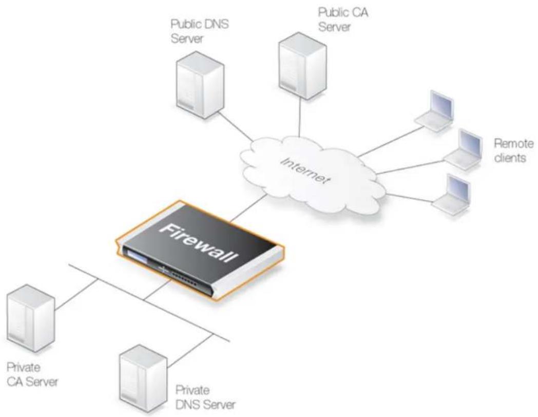
flowchart
graph TD
    A["Firewall"] --> B["Public DNS Server"]
    A --> C["Public CA Server"]
    A --> D["Internet"]
    A --> E["Private CA Server"]
    A --> F["Private DNS Server"]
    G["Remote clients"] --> H["Laptop"]
    G --> I["Laptop"]
    G --> J["Laptop"]
Figure 3.13. Certificate Validation Components
CA Server Access by Clients
In a VPN tunnel with roaming clients connecting to the D-Link firewall, the VPN client software may need to access the CA server. Not all VPN client software will need this access. In the Microsoft clients prior to Vista, CA server requests are not sent at all. With Microsoft Vista validation became the default with the option to disable it. Other non-Microsoft clients differ in the way they work but the majority will attempt to validate the certificate.
Placement of Private CA Servers
The easiest solution for placement of a private CA server is to have it on the unprotected side of the firewall. However, this is not recommended from a security viewpoint. It is better to place it on the inside (or preferably in the DMZ if available) and to have NetDefendOS control access to it.
As explained previously, the address of the private CA server must be resolvable through public DNS servers for certificate validation requests coming from the Internet. If the certificate queries are coming only from the D-Link firewall and the CA server is on the internal side of the firewall then the IP address of the internal DNS server must be configured in NetDefendOS so that these requests can be resolved.
Turning Off validation
As explained in the troubleshooting section below, identifying problems with CA server access can be done by turning off the requirement to validate certificates. Attempts to access CA servers by NetDefendOS can be disabled with the Disable CRLs option for certificate objects. This means that checking against the CA server's revocation list will be turned off and access to the server will not be attempted.
3.9.5. Creating Windows CA Server Requests
To request certificates from a CA server or CA company, the best method is to send a CA Certificate Request which is a file that contains a request for a certificate in a well-known, predefined format.
The NetDefendOS Web Interface (WebUI) does not include the ability to generate certificate requests that can be sent to a CA server for generation of the .cer and .key files required by NetDefendOS.
It is possible, however, to manually create the required files for a Windows CA server using the following stages.
- Create a gateway certificate on the Windows CA server and export it as a file in the .pfx format.
- Convert the .pfx file into the .pem format.
• Take out the relevant parts of the .pem file to form the required .cer and .key files.
The detailed steps for the above stages are as follows:
- Create the gateway certificate on the Windows CA server and export it to a .pfx file on the local NetDefendOS management workstation disk.
- Now convert the local .pfx file to a .pem file. This can be done with the OpenSSL utility using the console command line:
openssl pkcs12 -in gateway.pfx -out gateway.pem -nodes
In this command line example, the file exported from the CA server is assumed to be called gateway.pfx and it is assumed to be in the same local directory as the OpenSSL executable.
The original gateway.pfx file contained 3 certificates: CA root certificate, a personal certificate and a private key certificate. The gateway.pem file now contains these in format which can be cut and pasted with a text editor.

Note
OpenSSL is being used here as a conversion utility and not in its normal role as a communication utility.
-
Create two blank text files with a text editor, such as Windows Notepad. Give the files the same filename but use the extension .cer for one and .key for the other. For example, gateway.cer and gateway.key might be the names.
-
Start a text editor and open the downloaded .pem file and locate the line that begins:
----BEGIN RSA PRIVATE KEY----
- Mark and copy into the system clipboard that line and everything under it, up to and including the line:
----END RSA PRIVATE KEY----
-
Now paste the copied text into the .key file and save it.
-
Back in the .pem file, locate the line that begins:
----BEGIN CERTIFICATE----
and copy into the system clipboard that line and everything under it, up to and including:
----END CERTIFICATE----
- Now paste this copied text into the .cer file and save it.
The saved .key and .cer files are now ready for upload into NetDefendOS.
3.10. DNS
Overview
A DNS server can resolve a Fully Qualified Domain Name (FQDN) into the corresponding numeric IP address. FQDNs are unambiguous textual domain names which specify a node's unique position in the Internet's DNS tree hierarchy. FQDN resolution allows the actual physical IP address to change while the FQDN can stay the same.
A Uniform Resource Locator (URL) differs from an FQDN in that the URL includes the access protocol along with the FQDN. For example the protocol might be specified http://: for world wide web pages.
FQDNs are used in many aspects of a NetDefendOS configuration where IP addresses are unknown or where it makes more sense to make use of DNS resolution instead of using static IP addresses.
DNS with NetDefendOS
To accomplish DNS resolution, NetDefendOS has a built-in DNS client that can be configured to make use of up to three IPv4 and/or IPv6 DNS servers. These are called the Primary Server, the Secondary Server and the Tertiary Server. For DNS to function, at least the one (the primary) server must be configured. It is recommended to have at least two servers (a primary and a secondary) defined so that there is always a backup server available.
Features Requiring DNS Resolution
Having at least one DNS server defined is vital for functioning of the following features in NetDefendOS:
• Automatic time synchronization.
- Access to an external certificate authority server for CA signed certificates.
• UTM features that require access to external servers such as anti-virus and IDP.
• FQDN Address object resolution.
Example 3.51. Configuring DNS Servers
In this example, NetDefendOS will be configured to use one primary and one secondary IPv4 DNS server, having IPv4 addresses 10.0.0.1 and 10.0.0.2 respectively.
Command-Line Interface
gw-world:/> set DNS DNSServer1=10.0.0.1 DNSServer2=10.0.0.2
Web Interface
- Go to: System > Device > DNS
- Enter the following:
• Primary Server: 10.0.0.1
• Secondary Server: 10.0.0.2
- Click OK
Automatic DNS Address Assignment
DNS addresses can also be assigned by enabling DHCP (for IPv6) or DHCPv6 (for IPv6 addresses) for any interface that is connected to an external DHCP server. This is often used when accessing the Internet via an ISP and receiving all the required addresses from the ISP's DHCP server.
The DNS addresses that are received through DHCP on any interface will become the system wide NetDefendOS DNS servers if no static DNS addresses have already been configured. However, if static DNS addresses have been manually configured then any DNS server addresses received via DHCP on any interface will be ignored and the existing manually configured DNS addresses will not be affected.
Using DHCP for configuring DNS addresses is discussed further in Section 5.2, "IPv4 DHCP Client" and Section 5.6.1, "DHCPv6 Client".
DNS Lookup and IP Rule Sets
In the case of DNS server request being generated by NetDefendOS itself, no IP rule set entries need to be defined for the connection to succeed. This is because connections initiated by NetDefendOS are considered to be trusted. For example, this would be the case if NetDefendOS is accessing a CA server to establish the validity of a certificate and first needs to resolve the certificate's FQDN to an IP address.
Dynamic DNS and HTTP Poster
A DNS feature offered by NetDefendOS is the ability to explicitly inform DNS servers when the external IP address of the firewall has changed. This is sometimes referred to as Dynamic DNS and is useful where the firewall has an external address that can change.
Dynamic DNS can also be useful in IPsec VPN scenarios where both ends of the tunnel have dynamic IP addresses. If only one side of the tunnel has a dynamic address then the Auto Establish property of the IPsec Tunnel object can solve this problem.
Under Network > Network Services in the Web Interface, several dynamic DNS services are defined. The HTTP Poster client object is a generic dynamic DNS client with the following characteristics:
- Multiple HTTP Poster objects can be defined, each with a different URL and different optional settings.
- By default, an HTTP Poster object sends an HTTP GET request to the defined URL. Some servers require an HTTP POST request and to achieve this the option HTTP Post the Values should be enabled. This is usually needed when authentication parameters are being sent in the URL.
- By default, HTTP Poster does not automatically send the server request after NetDefendOS reconfiguration. This behavior can be changed by enabling the option Repost on each reconfiguration.
There is one exception to the default behavior and that is after a reconfigure which is the result of getting a new local IP address on the interface that connects to the DNS server.
In this case, NetDefendOS always waits a predefined period of 20 seconds before reposting after the reconfiguration.
• The default Repost Delay is 1200 seconds (20 minutes). This can be altered.
The predefined DynDNS client has an predefined refetch time of 30 days which cannot be changed.
The difference between HTTP Poster and the predefined named DNS servers is that HTTP Poster can be used to send any URL. The named services are a convenience that make it easy to correctly format the URL needed for that particular service. For example, the http://URL for the dyndns.org service might be:
myuid:mypwd@members.dyndns.org/nic/update?hostname=mydns.dyndns.org
This could be sent by using HTTP Poster. Alternatively, the URL could be automatically formatted for the administrator by NetDefendOS through using the DynDNS option and entering only the information required for dyndns.org.
HTTP Poster Reply Requirements
The following are the requirements for any replies sent back to an HTTP poster:
• The HTTP header must be valid with a response code of 200.
- The body of the response must contain some text and cannot be empty. This text will be used in the status message.
HTTP Poster Failure
If NetDefendOS detects a HTTP Poster failure, it will continue to retry the operation at successively longer intervals. The initial interval is 60 seconds and this interval is multiplied by 2 for each successive retry. When the interval reaches 24 hours, it is not multiplied by 2 any longer but continues retrying until the operation is successful.
The HTTP Poster generates log messages indicating success or failure. The CLI console command httpposter can be used to troubleshoot problems by seeing what NetDefendOS is sending and what the servers are returning:
gw-world:/> httpposter
Forcing a Repost
A repost for an individual server can be forced with the command:
gw-world:/> httpposter -repost=<index>
Where
gw-world:/> httpposter -repost=2
HTTP Poster Has Other Uses
HTTP Poster may be used for other purposes than dynamic DNS. Any requirement for NetDefendOS to send an HTTP GET or POST message to a particular URL could be met using this feature.

Note: A high rate of server queries can cause problems
Dynamic DNS services are often sensitive to repeated login attempts over short periods of time and may blacklist source IP addresses that are sending excessive requests. It is therefore not advisable to query these servers too often, otherwise they may cease to respond.
Chapter 4: Routing
This chapter describes how to configure IP routing in NetDefendOS.
• Overview, page 299
• Static Routing, page 300
• Policy-based Routing, page 322
- Route Load Balancing, page 330
• Active-Active Setup, page 337
• Virtual Routing, page 340
- OSPF, page 348
• Multicast Routing, page 378
- Transparent Mode, page 394
4.1. Overview
IP routing is one of the most fundamental functions of NetDefendOS. Any IP packet flowing through a D-Link firewall will be subjected to at least one routing decision at some point in time, and properly setting up routing is crucial for the system to function as expected.
NetDefendOS offers support for the following types of routing mechanisms:
- Static routing
- Dynamic routing
Additionally, NetDefendOS supports route monitoring to achieve route and link redundancy with failover capability.
4.2. Static Routing
The most basic form of routing is known as Static Routing. The term "static" is used because most entries in a routing table are part of the NetDefendOS system's static configuration. They usually remain unchanged during long periods of system operation.
Due to this manual approach, static routing is most appropriate to use in smaller network deployments where addresses are fairly fixed and where the amount of connected networks are limited to a few. However, for larger networks, or whenever the network topology is complex, the work of manually maintaining static routing tables can be time-consuming and also problematic. Dynamic routing should therefore be used in such cases.
For more information about the dynamic routing capabilities of NetDefendOS, please see Section 4.7, "OSPF". Note, however, that even if dynamic routing is chosen for a network, understanding the principles of static routing and how it is implemented in NetDefendOS is still required.
4.2.1. Static Routing in NetDefendOS
IP routing is the mechanism used in TCP/IP based networks for delivering IP packets from their source to their ultimate destination through a number of intermediary network devices. These devices are most often referred to as routers since they are performing the task of routing packets to their destination.
In each router, one or more routing tables contain a list of routes and these are consulted to find out where to send a packet so it can reach its destination. The components of a single route are discussed next.
The Components of a NetDefendOS Route
A NetDefendOS Route object can be added to a Routing Table. A Route object has following key properties:
- Interface
The interface to forward the packet on in order to reach the destination network. In other words, the interface to which the destination IP range is connected, either directly or through a router.
The interface might be a physical interface of the firewall or it might be VPN tunnel (tunnels are treated like physical interfaces by NetDefendOS).
- Network
This is the destination network IP address range which this route will reach. The route chosen from a routing table is the one that has a destination IP range which includes the IP address being sought. If there is more than one such matching route, the route chosen is the one which has the smallest IP address range.
The destination network all-nets is usually always used in the route for Internet access via an ISP.
• Gateway
The IP address of the gateway which is the next router in the path to the destination network. This is optional. If the destination network is connected directly to the interface, this is not needed.
When a router lies between the firewall and the destination network, a gateway IP must be
specified. For example, if the route is for Internet access via an ISP then the public IPv4 address of the ISP's gateway router would be specified.
- Local IP Address
This parameter usually does not need to be specified. If it is specified, NetDefendOS responds to ARP queries sent to this address. A special section below explains this parameter in more depth.
Local IP Address and Gateway are mutually exclusive and either one or the other should be specified.
• Metric
This is a metric value assigned to the route and is used as a weight when performing comparisons between alternate routes. If two routes are equivalent but have different metric values then the route with the lowest metric value is taken.
The metric value is also used by Route Failover and Route Load Balancing.
For more information, see Section 4.4, "Route Load Balancing" and Section 4.2.3, "Route Failover".
A Typical Routing Scenario
The diagram below illustrates a typical routing scenario.
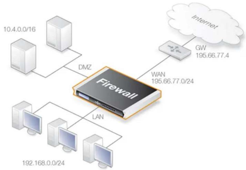
flowchart
graph TD
    A["10.4.0.0/16"] --> B["DMZ"]
    C["192.168.0.0/24"] --> D["LAN"]
    E["Internet"] --> F["GW 195.66.77.4"]
    F --> G["WAN 195.66.77.0/24"]
    G --> H["Firewall"]
Figure 4.1. A Typical Routing Scenario
In the above diagram, the LAN interface is connected to the network 192.168.0.0/24 and the DMZ interface is connected to the network 10.4.0.0/16. The WAN interface is connected to the network 195.66.77.0/24 and the address of the ISP gateway to the public Internet is 195.66.77.4.
The associated routing table for this would be as follows:
| Route # Interface Destination Gateway | |||
| 1 lan 192.168.0.0/24 | |||
| 2 dmz 10.4.0.0/16 | |||
| 3 wan 195.66.77.0/24 | |||
| 4 wan all-nets 195.66.77.4 |
The above routing table provides the following information:
- Route #1
All packets going to hosts on the 192.168.0.0/24 network should be sent out on the lan interface. As no gateway is specified for the route entry, the host is assumed to be located on the network segment directly reachable from the lan interface.
- Route #2
All packets going to hosts on the 10.4.0.0/16 network are to be sent out on the dmz interface. Also for this route, no gateway is specified.
- Route #3
All packets going to hosts on the 195.66.77.0/24 network will be sent out on the wan interface. No gateway is required to reach the hosts.
- Route #4
All packets going to any host (the all-nets network will match all hosts) will be sent out on the wan interface and to the gateway with IP address 195.66.77.4. That gateway will then consult its routing table to find out where to send the packets next.
A route with the destination all-nets is often referred to as the Default Route as it will match all packets for which no specific route has been configured. This route usually specifies the interface which is connected to the Internet.
The Narrowest Routing Table Match is Selected
When a routing table is evaluated, the ordering of the routes is not important. Instead, all routes in the relevant routing table are evaluated and the most specific route is used. In other words, if two routes have destination networks that overlap, the narrower network definition will be taken before the wider one. This behavior is in contrast to IP rule set matching where the first matching entry is used.
In the previous example, a packet with a destination IP address of 192.168.0.4 will theoretically match both the first route and the last one. However, the first route entry is a narrower, more specific match so the evaluation will end there and the packet will be routed according to that entry.
When two or more single host routes (routes with a single IP address) match then the route chosen is arbitrary. Given no changes in the configuration, that same route will be chosen every time.
Where two or more routes with an address range match and all have the same width, then the route chosen is the one with the lowest metric (this was mentioned previously in the description of the metric property).
Although routing table ordering is not important, it is still recommended for readability to try
and place narrower routes first and the default all-nets route last.
The Route Index is for Display Only
When routing tables are listed in a management interface, an index number is assigned to each route and this index can then be used to manipulate the route. It should be noted that this index is not fixed and is assigned by NetDefendOS when the table is displayed. Manually changing the index number can be done but this may only change a route's position in the table temporarily. A system restart can completely reorder a routing table, with routes getting new index numbers. This is especially true for routes that are automatically created by NetDefendOS.
As mentioned in the description above of routing table matching, the position of a route in a routing table has no effect on route selection.
The Local IP Address Parameter
The correct usage of the Local IP Address parameter can be difficult to understand so additional explanation can be helpful.
Normally, a physical interface such as Ian is connected to a single network and the interface and network are on the same network. We can say that the network is bound to a physical interface and clients on the connected network can automatically find the D-Link firewall through ARP queries. ARP works because the clients and the NetDefendOS interface are part of the same network.
A second network might then be added to the same physical interface via a switch, but with a new network range that does not include the physical interface's IP address. This network is said to be not bound to the physical interface. Clients on this second network will not then be able to communicate with the firewall because ARP will not function between the clients and the interface.
To solve this problem, a new route is added to NetDefendOS with the following parameters:
• Interface: The interface on which the second network is found.
• Network: The IP address range of the second network.
- Local IP Address: An address within the second network's IP range.
When the Default Gateway of the second network's clients is now set to the same value as the Local IP Address of the above route, the clients will be able to communicate successfully with the interface. The IP address chosen in the second network is not significant, as long as it is the same value for the Default Gateway of the clients and the Local IP Address.
The effect of adding the route with the Local IP Address is that the firewall will act as a gateway with the Local IP Address and respond to, as well as send out, ARP queries as though the interface had that IP address.
The diagram below illustrates a scenario where this feature could be used. The network 10.1.1.0/24 is bound to a physical interface that has an IP address within the network of 10.1.1.1. If we now attach a second network 10.2.2.0/24 to the interface via the switch, it is unbound since the interface's IP address does not belong to it.
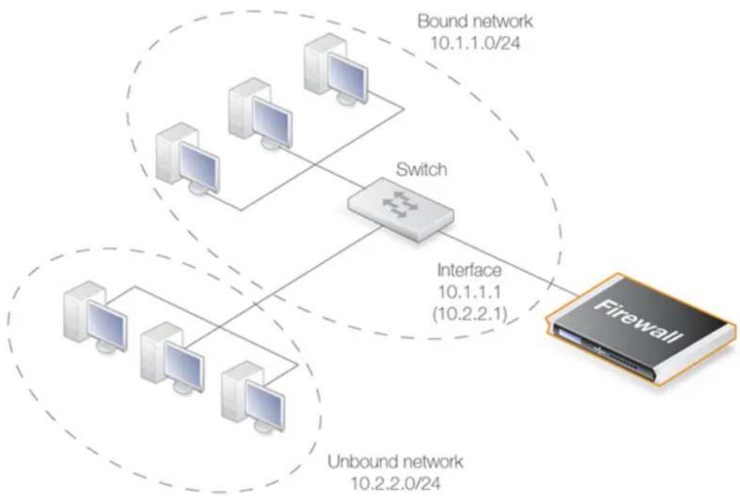
flowchart
graph TD
    A["Firewall"] --> B["Switch"]
    B --> C["Client 10.1.1.1 (10.2.2.1)"]
    B --> D["Client 10.1.1.0/24"]
    B --> E["Client 10.1.1.0/24"]
    B --> F["Unbound network 10.2.2.0/24"]
    G["Bound network 10.1.1.0/24"] --> B
Figure 4.2. Using Local IP Address with an Unbound Network
By adding a NetDefendOS route for this second network with the Local IP Address specified as 10.2.2.1, the interface will then respond to ARP requests from the 10.2.2.0/24 network. The clients in this second network must also have their Default Gateway set to 10.2.2.1 in order to reach the firewall.
This feature is normally used when an additional network is to be added to an interface but it is not desirable to change the existing IP addresses of the network. From a security standpoint, doing this can present significant risks since different networks will typically be joined together through a switch which imposes no controls on traffic passing between those networks. Caution should therefore be exercised before using this feature.
All Traffic Must have Two Associated Routes
Something that is not intuitive when trying to understand routing in NetDefendOS is the fact that all traffic must have two routes associated with it. Not only must a route be defined for the destination network of a connection but also for the source network.
The route that defines the source network simply says that the source network is found on a particular interface. When a new connection is opened, NetDefendOS performs a check known as a reverse route lookup which looks for this route. The source network route is not used to perform routing but instead as a check that the source network should be found on the interface where it arrived. If this check fails, NetDefendOS generates a Default Access Rule error log message.
Even traffic destined for Core (NetDefendOS itself), such as ICMP ping requests must follow this rule of having two routes associated with it. In this case, the interface of one of the routes is specified as Core.
4.2.2. Configuring Static Routes
This section describes how routing is implemented in NetDefendOS, and how to configure static routing.
NetDefendOS supports multiple routing tables. A default table called main is predefined and is always present in NetDefendOS. However, additional and completely separate routing tables can be defined by the administrator to provide alternate routing.
Extra, user-defined routing tables can be used in two ways:
- Virtual Routing associates interfaces with a particular routing table. This enables a single NetDefendOS installation to act as multiple virtual systems. Communication between these systems is achieved with Loopback Interfaces (see Section 4.6, "Virtual Routing" and also Section 3.4.9, "Loopback Interfaces").
- Policy Based Routing Rules can be defined which decide which of the routing tables will deal with certain types of traffic (see Section 4.3, "Policy-based Routing").
The Route Lookup Mechanism
The NetDefendOS route lookup mechanism has some slight differences to how some other router products work. In many routers, where the IP packets are forwarded without context (in other words, the forwarding is stateless), the routing table is scanned for each and every IP packet received by the router. In NetDefendOS, packets are forwarded with state-awareness, so the route lookup process is tightly integrated into the NetDefendOS stateful inspection mechanism.
When an IP packet is received on any of the interfaces, the connection table is consulted to see if there is an already open connection for which the received packet belongs. If an existing connection is found, the connection table entry includes information on where to route the packet so there is no need for lookups in the routing table. This is far more efficient than traditional routing table lookups, and is one reason for the high forwarding performance of NetDefendOS.
If an established connection cannot be found, then the routing table is consulted. It is important to understand that the route lookup is performed before any of the various policy rules get evaluated (for example, IP rule set lookup). Consequently, the destination interface is known at the time NetDefendOS decides if the connection should be allowed or dropped. This design allows for a more fine-grained control in security policies.
NetDefendOS Route Notation
NetDefendOS uses a slightly different way of describing routes compared to most other systems but this way is easier to understand, making errors less likely.
Many other products do not use the specific interface in the routing table, but specify the IP address of the interface instead. The routing table below, is from a Microsoft Windows workstation:
Interface List
0x1 .... MS TCP Loopback interface
0x10003 ...00 13 d4 51 8d dd ..... Intel(R) PRO/1000 CT Network
0x20004 ...00 53 45 00 00 00 ..... WAN (PPP/SLIP) Interface

Active Routes:
Network Destination Netmask Gateway Interface Metric
    0.0.0.0    0.0.0.0   192.168.0.1   192.168.0.10    20
    10.0.0.0   255.0.0.0    10.4.2.143    10.4.2.143 1
    10.4.2.143    255.255.255.255   127.0.0.1   127.0.0.1    50
10.255.255.255 255.255.255.255 10.4.2.143 10.4.2.143 50
85.11.194.33 255.255.255.255 192.168.0.1 192.168.0.10 20
127.0.0.0 255.0.0.0 127.0.0.1 127.0.0.1 1
192.168.0.0 255.255.255.0 192.168.0.10 192.168.0.10 20
192.168.0.10 255.255.255.255 127.0.0.1 127.0.0.1 20
192.168.0.255 255.255.255.255 192.168.0.10 192.168.0.10 20
224.0.0.0 240.0.0.0 10.4.2.143 10.4.2.143 50
224.0.0.0 240.0.0.0 192.168.0.10 192.168.0.10 20
255.255.255.255 255.255.255.255 10.4.2.143 10.4.2.143 1
255.255.255.255 255.255.255.255 192.168.0.10 192.168.0.10 1
Default Gateway: 192.168.0.1

Persistent Routes:
None
The corresponding routing table in NetDefendOS will be similar to the following:
Flags Network Iface Gateway Local IP Metric
192.168.0.0/24 lan 20
10.0.0.0/8 wan 1
0.0.0.0/0 wan 192.168.0.1 20
NetDefendOS Route Definition Advantages
The NetDefendOS method of defining routes makes the reading and understanding of routing information easier.
A further advantage with the NetDefendOS approach is that the administrator can directly specify a gateway for a particular route and the following is true:
• A separate route does not need to be defined that includes the gateway IP address.
- It does not matter even if there is a separate route which includes the gateway IP address and that routes traffic to a different interface.
Composite Subnets can be Specified
Another advantage with the NetDefendOS approach to route definition is that it allows the administrator to specify routes for destinations that are not aligned with traditional subnet masks.
For example, it is perfectly legal to define one route for the destination IP address range 192.168.0.5 to 192.168.0.17 and another route for IP addresses 192.168.0.18 to 192.168.0.254. This is a feature that makes NetDefendOS highly suitable for routing in highly complex network topologies.
Displaying Routing Tables
It is important to note that routing tables that are initially configured by the administrator can have routes added, deleted and changed automatically during live operation and these changes will appear when the routing table contents are displayed.
These routing table changes can take place for different reasons. For example, if dynamic routing with OSPF has been enabled then routing tables will become populated with new routes learned from communicating with other OSPF routers in an OSPF network. Other events such as route
failover can also cause routing table contents to change over time.
Example 4.1. Displaying the main Routing Table
This example illustrates how to display the contents of the default main routing table.
Command-Line Interface
To see the routing table contents:
gw-world:/> cc RoutingTable main
gw-world:/main> show
Route
    # Interface Network Gateway Local IP
    ----
    1 wan all-nets 213.124.165.1 <empty>
    2 lan lannet <empty> <empty>
    3 wan wannet <empty> <empty>
To return the default CLI context:
gw-world:/main> cc
gw-world:/>
To see the active routing table enter:
gw-world:/> routes
Flags Network Iface Gateway Local IP Metric
192.168.0.0/24 lan 0
213.124.165.0/24 wan 0
0.0.0.0/0 wan 213.124.165.1 0
Web Interface
To see the configured routing table:
-
Go to: Network > Routing > Routing Tables
-
Select the main routing table
The main window will list the configured routes
To see the active routing table in the Web Interface, select the Routes item in the Status dropdown menu in the menu bar - the main window will list the active routing table

Tip: The cc command may be needed to change context
In the CLI example above, it was necessary to first select the name of a specific routing table with the cc command (meaning change category or change context) before manipulating individual routes.
Default Static Routes are Added Automatically for Each Interface
When the D-Link firewall is started for the first time, NetDefendOS will automatically add a route in the main routing table for each physical interface. These routes are assigned a default IP address object in the address book and these IP objects must have their addresses changed to the appropriate range for traffic to flow.

Note: The metric for default routes is 100
The metric assigned to the default routes automatically created for the physical interfaces is always 100.
These automatically added routes cannot be removed manually by deleting them one at a time from a routing table. Instead, the properties of the interface must be selected and the advanced option Automatically add a route for this interface using the given network must be disabled. This will remove any route that was added automatically at startup. This option has no other purpose but to delete the automatically added routes.
The all-nets Route
The most important route that should be defined is the route to all-nets which usually corresponds to an ISP that provides Internet access. If using the NetDefendOS setup wizard, this route is also added automatically.
However, the option also exists for any physical interface to indicate that it should be used for connection to the Internet. In the Web Interface this is an advanced setting in the Ethernet interface properties called:
Automatically add a default route for this interface using the given default gateway.
When this option is selected, the appropriate all-nets route is automatically added to the main routing table for the interface.
Example 4.2. Adding a Route to the main Table
This example shows how an all-nets route is added to the routing table called main. This route will be for the ISP connected to the wan interface and the ISP is accessed via a router with the IP address isp_gw_ip which will be the gateway for the route.
Command-Line Interface
Change the context to be the routing table:
gw-world:/> cc RoutingTable main
Add the route:
gw-world:/main> add Route
Interface=wan
Network=all-nets
Gateway=isp_gw_ip
Return to the default CLI context:
gw-world:/main> cc
gw-world:/>
Web Interface
-
Go to: Network > Routing > Routing Tables > main > Add > Route
-
Now enter:
-
Interface: wan
• Network: all-nets -
Gateway: isp_gw_ip
-
Click OK
Routes can Contain IPv4 or IPv6 Addresses
A single route can contain either an IPv4 or IPv6 address but not both. Routes that use IPv4 and IPv6 addresses can be mixed in the same routing table. This topic is described further in Section 3.2, "IPv6 Support".
Routes with core as the Interface
NetDefendOS automatically populates the active routing table with core routes. These routes are present for NetDefendOS to understand how to route traffic that is destined for NetDefendOS itself. A good example for such traffic are ICMP ping messages sent to an Ethernet interface, where NetDefendOS itself that must handle and respond to the ping request.
There is one route added for each Ethernet interface in the system. For example, if there two interfaces named lan and wan with the IPv4 addresses 192.168.0.10 and 193.55.66.77, this will result in the following routes existing:
| Route # Interface Destination Gateway | |||
| 1 core 192.168.0.10 | |||
| 2 core 193.55.66.77 |
When the system receives an IP packet whose destination address is one of the interface IPs, the packet will be routed to the core interface. In other words, it is processed by NetDefendOS itself.
There is also a core route added for all multicast addresses:
| Route # Interface Destination Gateway | |||
| 1 core 224.0.0.0/4 |
To include the core routes when the active routing table is displayed, it is necessary to explicitly specify that all routes are to be displayed. This is shown in the example below.
Example 4.3. Displaying the Core Routes
This example illustrates how to display the core routes in the active routing table.
Command-Line Interface
gw-world:/> routes -all
Flags Network Iface Gateway Local IP Metric
127.0.0.1 core (Shared IP) 0
192.168.0.1 core (Iface IP) 0
213.124.165.181 core (Iface IP) 0
127.0.3.1 core (Iface IP) 0
127.0.4.1 core (Iface IP) 0
192.168.0.0/24 lan 0
213.124.165.0/24 wan 0
224.0.0.0/4 core (Iface IP) 0
0.0.0.0/0 wan 213.124.165.1 0
Web Interface
- Select the Routes item in the Status dropdown menu in the menu bar
- Check the Show all routes checkbox and click the Apply button
- The main window will list the active routing table, including the core routes

Tip: Understanding output from the routes command
For detailed information about the output of the CLI routes command, refer to the separate CLI Reference Guide.
4.2.3. Route Failover
Overview
D-Link firewalls are often deployed in mission-critical locations where availability and connectivity is crucial. For example, an enterprise relying heavily on access to the Internet could have operations severely disrupted if a single connection to the external Internet via a single Internet Service Provider (ISP) fails.
It is therefore not unusual to have backup Internet connectivity using a secondary ISP. The connections to the two service providers often use different routes to avoid a single point of failure.
To allow for a situation with multiple ISPs, NetDefendOS provides a Route Failover capability so that should one route fail, traffic can automatically failover to another, alternate route. NetDefendOS implements route failover through the use of Route Monitoring in which NetDefendOS monitors the availability of routes and then switches traffic to an alternate route should the primary, preferred route fail.
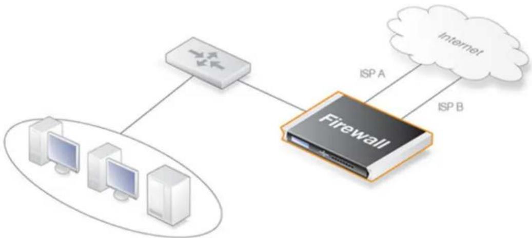
flowchart
graph TD
    A["Router"] -->|ISP A| B["Firewall"]
    C["Client 1"] -->|ISP A| B
    D["Client 2"] -->|ISP A| B
    E["Client 3"] -->|ISP A| B
    B --> F["Internet"]
Figure 4.3. A Route Failover Scenario for ISP Access
Setting Up Route Failover
To set up route failover, Route Monitoring must be enabled and this is an option that is enabled on a route by route basis. To enable route failover in a scenario with a preferred and a backup route, the preferred route will have route monitoring enabled, however the backup route does not require this since it will usually have no route to failover to. When route monitoring is enabled for a route, one of the following monitoring methods must be chosen:
- Interface Link Status
NetDefendOS will monitor the link status of the interface specified in the route. As long as the interface is up, the route is diagnosed as healthy. This method is appropriate for monitoring that the interface is physically attached and that the cabling is working as expected. As any changes to the link status are instantly noticed, this method provides the fastest response to failure.
• Gateway Monitoring
If a specific gateway has been specified as the next hop for a route, accessibility to that gateway can be monitored by sending periodic ARP requests. As long as the gateway responds to these requests, the route is considered to be functioning correctly.
- Host Monitoring
The first two options check the accessibility of components local to the D-Link firewall. An alternative is to monitor the accessibility of one or more nominated remote hosts. These hosts might have known high availability and polling them can indicate if traffic from the local firewall is reaching them. Host monitoring also provides a way to measure the network delays in reaching remote hosts and to initiate failover to an alternate route if delays exceed administrator-specified thresholds.
Automatically Added Routes Need Redefining
It is important to note that the route monitoring cannot be enabled on automatically added routes. For example, the routes that NetDefendOS creates at initial startup for physical interfaces are automatically added routes. The reason why monitoring cannot be enabled for these routes is because automatically created routes have a special status in an NetDefendOS configuration
and are treated differently.
If route monitoring is required on an automatically created route, the route should first be deleted and then recreated manually as a new route. Monitoring can then be enabled on the new route.
Setting the Route Metric
When specifying routes, the administrator should manually set a route's Metric. The metric is a positive integer that indicates how preferred the route is as a means to reach its destination. When two routes offer a means to reach the same destination, NetDefendOS will select the one with the lowest metric value for sending data (if two routes have the same metric, the route found first in the routing table will be chosen).
A primary, preferred route should have a lower metric (for example "10"), and a secondary, failover route should have a higher metric value (for example "20").
Multiple Failover Routes
It is possible to specify more than one failover route. For instance, the primary route could have two other routes as failover routes instead of just one. In this case the metric should be different for each of the three routes: "10" for the primary route, "20" for the first failover route and "30" for the second failover route. The first two routes would have route monitoring enabled in the routing table but the last one (with the highest metric) would not since it has no route to failover to.
Failover Processing
Whenever monitoring determines that a route is not available, NetDefendOS will mark the route as disabled and instigate route failover for existing and new connections. For already established connections, a route lookup will be performed to find the next best matching route and the connections will then switch to using the new route. For new connections, route lookup will ignore disabled routes and the next best matching route will be used instead.
The table below defines two default routes, both having all-nets as the destination, but using two different gateways. The first, primary route has the lowest metric and also has route monitoring enabled. Route monitoring for the second, alternate route is not meaningful since it has no failover route.
| Route # Interface Destination Gateway Metric Monitoring | |||||
| 1 wan all-nets | 195.66.77.1 | 10 | On | ||
| 2 wan all-nets | 193.54.68.1 | 20 | Off | ||
When a new connection is about to be established to a host on the Internet, a route lookup will result in the route that has the lowest metric being chosen. If the primary WAN router should then fail, this will be detected by NetDefendOS, and the first route will be disabled. As a consequence, a new route lookup will be performed and the second route will be selected with the first one being marked as disabled.
Re-enabling Routes
Even if a route has been disabled, NetDefendOS will continue to check the status of that route. Should the route become available again, it will be re-enabled and existing connections will automatically be transferred back to it.
Route Interface Grouping
When using route monitoring, it is important to check if a failover to another route will cause the routing interface to be changed. If this could happen, it is necessary to take some precautionary steps to ensure that policies and existing connections will be maintained.
To illustrate the problem, consider the following configuration:
Firstly, there is one IP rule set entry that will NAT all HTTP traffic destined for the Internet through the wan interface:
| Action | Src Iface | Src Net | Dest Iface | Dest Net | Parameters |
| Allow/NAT lan lannet | wan all-nets http-all |
The routing table consequently contains the following default route:
| Interface | Destination | Gateway | Metric | Monitoring |
| wan | all-nets | 195.66.77.1 10 | Off |
Now a secondary route is added over a backup DSL connection and route monitoring is enabled for this. The updated routing table will look like this:
| Route # | Interface | Destination | Gateway | Metric | Monitoring |
| 1 | wan all-nets 195.66 | 77.1 10 | On | ||
| 2 | dsl | all-nets | 193.54.68.1 | 20 | Off |
Notice that route monitoring is enabled for the first route but not the backup, failover route.
As long as the preferred wan route is healthy, everything will work as expected. route monitoring will also be functioning, so the secondary route will be enabled if the wan route should fail.
However, there are some problems with this setup: if a route failover occurs, the default route will then use the dsl interface. When a new HTTP connection is established, a route lookup will be made resulting in a destination interface of dsl. The IP rule set will then be evaluated, but the original NAT IP policy assumes the destination interface to be wan so the new connection will be dropped by the rule set.
In addition, any existing connections matching the NAT rule will also be dropped as a result of the change in the destination interface. Clearly, this is undesirable.
To overcome this issue, potential destination interfaces should be grouped together into an Interface Group and the Security/Transport Equivalent option should be enabled for the group so that connections can be moved between interfaces. The interface group is then used as the destination interface when setting policies. For more information on interface groups, see Section 3.4.10, "Interface Groups".
Gratuitous ARP Generation
By default NetDefendOS generates a gratuitous ARP request when a route failover occurs. The reason for this is to notify surrounding systems that there has been a route change. This behavior can be controlled by the advanced setting Gratuitous ARP on Fail (this is found in the Web Interface in Network >Routing >Routing Settings).
4.2.4. Host Monitoring for Route Failover
Overview
To provide a more flexible and configurable way to monitor the integrity of routes, NetDefendOS provides the additional capability to perform Host Monitoring. This feature means that one or more external host systems can be routinely polled to check that a particular route is available.
The advantages of host monitoring are twofold:
- In a complex network topology it is more reliable to check accessibility to external hosts. Just monitoring a link to a local switch may not indicate a problem in another part of the internal network.
- Host monitoring can be used to help in setting the acceptable Quality of Service level of Internet response times. Internet access may be functioning but it may be desirable to instigate route failover if response latency times become unacceptable using the existing route.
Enabling Host Monitoring
Host monitoring can be enabled as a property of a Route object and a single route can have multiple hosts associated with it for monitoring. Multiple hosts can provide a higher certainty that any network problem resides in the local network rather than because one remote host itself is down.
In association with host monitoring there are two numerical parameters for a route:
Grace Period This is the period of time after startup or after
reconfiguration of the D-Link firewall when NetDefendOS will wait before starting monitoring. This waiting period allows time for all network links to initialize once the firewall comes online.
Minimum Number of Hosts Available
This is the minimum number of hosts that must be considered to be accessible before the route is deemed to have failed. The criteria for host accessibility are described below.
Specifying Hosts
For each host specified for host monitoring, there are a number of property parameters that should be set:
• Method
The method by which the host is to be polled. This can be one of:
- ICMP - ICMP "Ping" polling. An IP address must be specified for this.
- TCP - A TCP connection is established to and then disconnected from the host. An IP address must be specified for this.
- HTTP - A normal HTTP server request using a URL. A URL must be specified for this as well as a text string which is the beginning (or complete) text of a valid response. If no text is specified, any response from the server will be valid.
- IP Address
The IP address of the host when using the ICMP or TCP option.
- Port Number
The port number for polling when using the TCP option.
- Source IP Selection
The source IP for the outgoing monitoring packets can be set to a specific value. By default, the IP address of the sending interface is used (the Automatic option) but it can be set by setting this property to Manual and specifying an IP address.
- Interval
The interval in milliseconds between polling attempts. The default setting is 10,000 and the minimum value allowed is 100 ms.
- Sample
The number of polling attempts used as a sample size for calculating the Percentage Loss and the Average Latency. This value cannot be less than 1.
• Maximum Failed Poll Attempts
The maximum permissible number of polling attempts that fail. If this number is exceeded then the host is considered unreachable.
• Max Average Latency
The maximum number of milliseconds allowable between a poll request and the response. If this threshold is exceeded then the host is considered unreachable. Average Latency is calculated by averaging the response times from the host. If a polling attempt receives no response then it is not included in the averaging calculation.
The Reachability Required Option
An important option that can be enabled for a host is the Reachability Required option. When this is selected, the host must be determined as accessible in order for that route to be considered to be functioning. Even if other hosts are accessible, this option says that the accessibility of a host with this option set is mandatory.
Where multiple hosts are specified for host monitoring, more than one of them could have Reachability Required enabled. If NetDefendOS determines that any host with this option enabled is not reachable, Route Failover is initiated.
HTTP Parameters
If the HTTP polling method is selected then two further parameters can be entered:
- Request URL
The URL which is to be requested.
- Expected Response
The text that is expected back from querying the URL.
Testing for a specific response text provides the possibility of testing if an application is
offline. If, for example, a web page response from a server can indicate if a specific database is operational with text such as "Database OK", then the absence of that response can indicate that the server is operational but the application is offline.
A Known Issue When No External Route is Specified
With connections to an Internet ISP, an external network route should always be specified. This external route specifies on which interface the network which exists between the D-Link firewall and the ISP can be found. If only an all-nets route is specified to the ISP's gateway, route failover may, depending on the connected equipment, not function as expected.
This issue rarely occurs but the reason why it occurs is that ARP queries arriving on a disabled route will be ignored.
4.2.5. Advanced Routing Settings for Route Failover
The following advanced routing settings are available for route failover and these can be found in the Web Interface by going to Network > Routing > Routing Settings:
Iface poll interval
The time in milliseconds between polling for interface failure.
Default: 500
ARP poll interval
The time in milliseconds between ARP-lookup of hosts. This may be overridden in individual routes.
Default: 1000
Ping poll interval
The time in milliseconds between sending a Ping to hosts.
Default: 1000
Grace time
The length of time in seconds between startup or reconfigure and monitoring start.
Default: 30
consecutive fails
The number of consecutive failures that occurs before a route is marked as being unavailable.
Default: 5
Consecutive success
The number of consecutive successes that must occur before a route is marked as being available.
Default: 5
Gratuitous ARP on fail
Send a gratuitous ARP on HA failover to alert hosts of the changes in interface Ethernet and IP addresses.
Default: Enabled
4.2.6. Proxy ARP
Overview
As discussed previously in Section 3.5, "ARP", the ARP protocol facilitates a mapping between an IP address and the MAC address of a host on an Ethernet network.
However, situations may exist where a network running Ethernet is separated into two parts with a routing device such as a D-Link firewall in between. In such a case, NetDefendOS itself can respond to ARP requests directed to the network on the other side of the firewall using the feature known as Proxy ARP.
The splitting of an Ethernet network into distinct parts so that traffic between them can be controlled is a common usage of the proxy ARP feature. NetDefendOS rule sets can then be used to impose security policies on the traffic passing between the different network parts.
A Typical Scenario
As an example of a typical proxy ARP scenario, consider a network split into two sub-networks with a D-Link firewall between the two.
Host A on one sub-network might send an ARP request to find out the MAC address for the IP address of host B on the other sub-network. With the proxy ARP feature configured, NetDefendOS responds to this ARP request instead of host B. NetDefendOS sends its own MAC address in reply, pretending to be the target host. After receiving the reply, Host A then sends data directly to NetDefendOS which forwards the data to host B. In the process NetDefendOS checks the traffic against the configured rule sets.
Setting Up Proxy ARP
Setting up proxy ARP is done by specifying the option for a route in a routing table. Suppose there is a network that is divided into two parts called net_1 and net_2.
The network net_1 is connected to the interface if1 and the network net_2 is connected to the interface if2. In NetDefendOS there will be a route configured that says net_1 can be found on if1. This might be called route_1.
For route_1 it is possible to specify the option that this network should be proxy ARPed on interface if2. Now any ARP request issued by a net_2 host connected to if2 looking for an IP address in net_1 will get a positive response from NetDefendOS. In other words, NetDefendOS will pretend that the net_1 address is found on if2 and will forward data traffic to net_1.
In the same way, net_2 could be published on the interface if1 so that there is a mirroring of routes and ARP proxy publishing.
| Route # Network Interface Proxy ARP Published | ||
| 1 net_1 if1 if2 | ||
| 2 net_2 if2 if1 |
In this way there is complete separation of the sub-networks but the hosts are unaware of this. The routes are a pair which are a mirror image of each other but there is no requirement that proxy ARP is used in a pairing like this.
Keep in mind that if the host has an ARP request for an IP address outside of the local network then this will be sent to the gateway configured for that host. The entire example is illustrated below.
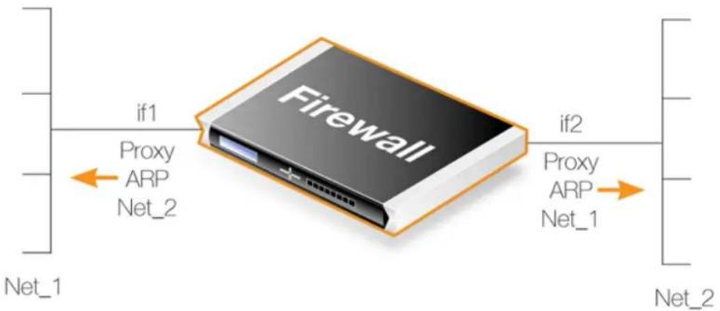
flowchart
graph LR
    A["Firewall"] -->|if1 Proxy ARP Net_2| B["Net_1"]
    A -->|if2 Proxy ARP Net_1| C["Net_2"]
Figure 4.4. A Proxy ARP Example
Transparent Mode as an Alternative
Transparent Mode is an alternative and preferred way of splitting Ethernet networks. Setup is simpler than using proxy ARP since only the appropriate switch routes need to be defined. Using switch routes is fully explained in Section 4.9, "Transparent Mode".
Proxy ARP depends on static routing where the location of networks on interfaces are known and usually fixed. Transparent mode is more suited to networks whose interface location can change.
Proxy ARP and High Availability Clusters
In HA clusters, switch routes cannot be used and transparent mode is therefore not an option. However, proxy ARP does function with HA and is consequently the only way to implement transparent mode functionality with a cluster.

Note: Not all interfaces can make use of Proxy ARP
It is only possible to have Proxy ARP functioning for Ethernet and VLAN interfaces. Proxy ARP is not relevant for other types of NetDefendOS interfaces since ARP is not involved.
Automatically Added Routes
Proxy ARP cannot be enabled for automatically added routes. For example, the routes that NetDefendOS creates at initial startup for physical interfaces are automatically added routes. The reason why Proxy ARP cannot be enabled for these routes is because automatically created routes have a special status in the NetDefendOS configuration and are treated differently.
If Proxy ARP is required on an automatically created route, the route should first be deleted and then manually recreated as a new route. Proxy ARP can then be enabled on the new route.
4.2.7. Broadcast Packet Forwarding
Broadcast packets are those packets which have the highest IP address in their network and will have an associated MAC address of FF:FF:FF:FF:FF:FF. For example, a broadcast packet for the network 192.168.1.0/24 will have the IPv4 address 192.168.1.255.
By default, NetDefendOS will drop all such broadcast packets arriving at an interface. In some situations, particularly when using transparent mode, it is desirable for NetDefendOS to forward these packets to another interface by doing a route lookup and also applying IP rule set entries to determine if the traffic should be forwarded.
Enabling Broadcast Packet Forwarding
To enable broadcast packet forwarding, the administrator should perform the following steps:
- Enable the Forward Broadcast Traffic property on a Route object (the BroadcastFwd property in the CLI). However, this must always be done on the routes for both the packet's source and destination interface.
- For non-transparent mode traffic only, the global IP setting Direct Broadcast must be enabled for broadcast forwarding to work. The setting's value is DropLog by default and it must be set to Ignore or Log for broadcast packets to be forwarded.
Even with broadcast packet forwarding enabled, NetDefendOS will still perform a check on broadcast packets arriving at an interface to ensure that a broadcast IPv4 address matches with a FF:FF:FF:FF:FF:FF MAC address. Packets with a mismatch are dropped.
Using Address Translation with Broadcast Forwarding
The following should be noted if address translation is used with broadcast forwarded traffic.
• SAT
SAT translation can be used with broadcast packets if appropriate. With SAT translation the destination address would always be the broadcast address.
• NAT
NAT translation cannot be used with broadcast packets in transparent mode. The packets will be dropped and a log message will be generated when they encounter the NAT IP policy.
NAT can be used with broadcast packets in non-transparent mode routing. This might be appropriate in some unusual networking scenarios.
Transparent Mode Broadcast Forwarding is Always Stateless
It is important to note that broadcast packets are always forwarded statelessly by NetDefendOS when in transparent mode. In other words, even if an IP rule set entry with an action of Allow
permits transparent mode broadcast packets to flow, they will be forwarded as though the entry was a Stateless Policy (or a FwdFast IP rule).
The reason for enforcing stateless forwarding is because packets may need to be duplicated and transmitted on multiple interfaces. For normal, non-transparent routes where broadcast packets are not duplicated, a normal Allow rule or policy could be used and the traffic will be treated statefully. A stateful IP policy has the advantage of using less hardware resources to process broadcast packets when many are coming from the same source.
Only Triggering an IP Policy on Broadcast Packets
When creating an IP policy which triggers only on broadcast packets, the Destination Network property should be set to be the broadcast IP address. However, the Source Network should be the network to which the broadcast address belongs. For example, a broadcast packet for the IPv4 network 10.0.0.0/8 will have the address 10.255.255.255 (the highest IP address in the network). So in an IP rule set entry targeting these packets, the Source Network property should be set to 10.0.0.0/8 and the Destination Network property should be set to 10.255.255.255.
Log Messages for Broadcast Packets
Log messages are only generated for broadcast packets that trigger an IP rule set entry when in transparent mode (using switch routes). There are only two messages that can be generated:
- allow\_broadcast
This log message is generated each time a broadcast packet triggers an IP rule set entry with an action of Allow in transparent mode. It indicates that the packet has been forwarded statelessly as though the rule had an action of FwdFast (or the policy was a Stateless Policy). A typical log message of this type will look similar to the following:
prio=Notice id=06000016 rev=1 event=allow_broadcast
action=stateless_fwd rule=a recvif=If3 srcip=192.168.100.25
destip=192.168.100.255 ipproto=UDP ipdatalen=58 srcport=137
destport=137 udptotlen=58
It should be noted that this event message will be generated for every interface that the broadcast packet is sent on. For example, if interfaces if1, if2 and if3 are all defined as being on the same network using transparent mode, a broadcast packet for the network could trigger an IP policy twice, generating two log messages. This is because the broadcast packet would arrive on one interface and would need transmitting on the other two.
All these multiple log messages can be turned off by disabling log messages on the triggering IP policy.
- broadcast\_nat
This is generated when a broadcast packet has triggered a NAT IP policy in transparent mode and has been dropped. A typical log message of this type will look similar to the following:
prio=Notice id=06000014 rev=1 event=broadcast_nat action=drop rule=a recvif=If3 srcip=192.168.100.25 destip=192.168.100.255 ipproto=UDP ipdatalen=58 srcport=137 destport=137 udptotlen=58
Broadcast packets triggering a NAT rule can optionally be dropped silently with a log message being generated. This is controlled by a global setting called
TransparentBroadcastNAT. The default value for this setting is DropLog. This should be set to Drop if no log messages are to be generated.
Example 4.4. Enabling Broadcast Forwarding on a Route
This example shows how to enable broadcast packet forwarding on an existing route called my_route which is the third route in the main routing table.
Command-Line Interface
First, enable broadcast forwarding globally for non-transparent mode traffic:
gw-world:/> set Settings IPSettings DirectedBroadcasts=Log
Next, enable broadcasting forwarding on the relevant route. Change the context to be the main routing table:
gw-world:/> cc RoutingTable main
Add the route:
gw-world:/main> set Route 3 BroadcastFwd=Yes
Return to the default CLI context:
gw-world:/main> cc
gw-world:/>
Web Interface
First, enable broadcast forwarding globally for non-transparent mode traffic:
- Go to: System > Advanced Settings > IP Settings
- Set Directed Broadcasts to Log
- Click OK
Next, enable broadcasting forwarding on the relevant route:
- Go to: Network > Routing > Routing Tables > main
- Select the route my_route
- Enable the option Forward Broadcast Traffic
- Click OK
4.3. Policy-based Routing
Overview
Policy-based Routing (PBR) is an extension to the standard routing described previously. It offers administrators significant flexibility in implementing routing decision policies by being able to use different routing tables according to specified criteria.
Normal routing forwards packets according to destination IP address information derived from static routes or from a dynamic routing protocol. For example, using OSPF, the route chosen for packets will be the least-cost (shortest) path derived from an SPF calculation. Policy-based routing means that routes chosen for traffic can be based on specific traffic parameters.
Policy-based routing allows the following to be possible:
- Source-based Routing
A different routing table may need to be chosen based on the source of traffic. When more than one ISP is used to provide Internet services, policy-based routing can route traffic originating from different sets of users through different routes.
For example, traffic from one address range might be routed through one ISP, whilst traffic from another address range might be through a second ISP.
• Service-based Routing
A different routing table might need to be chosen based on the service. Policy-based routing can route a given protocol such as HTTP, through proxies such as Web caches. Specific services might also be routed to a specific ISP so that one ISP handles all HTTP traffic.
- User-based Routing
A different routing table might need to be chosen based on the user identity or the group to which the user belongs.
This is particularly useful in provider-independent metropolitan area networks where all users share a common active backbone but each can use different ISPs and subscribe to different providers.
PBR Components
Policy-based routing implementation in NetDefendOS is implemented using two components:
• Additional Routing Tables
One or more user-defined alternate Routing Tables are created in addition to the standard default main routing table.
- Routing Rules
One or more Routing Rules are created to determine which routing table to use for which traffic.
Without routing rules, the main routing table is the default. However, an alternate routing table can also be explicitly assigned as the default table for a given interface without the use of rules.
Routing Tables
NetDefendOS, as standard, has one default routing table called main. In addition to the main table, it is possible to define one or more, additional routing tables for policy-based routing. (these will sometimes be referred to as alternate routing tables).
Alternate routing tables contain the same information for describing routes as main, except that there is an extra property defined for each of them which is called ordering. The ordering property decides how route lookup is done using alternate tables in conjunction with the main table. This is described further below.

Note: The number of tables is limited by the model
The maximum number of routing tables that can be created is limited by the type of D-Link hardware model.
Example 4.5. Creating a Routing Table
In this example, a new routing table called MyPBRTable is created with the Ordering property set to First.
Command-Line Interface
To see the configured routing table:
gw-world:/> add RoutingTable MyPBRTable Ordering=First
Web Interface
- Go to: Network > Routing > Routing Tables > Add > RoutingTable
-
Now enter:
-
Name: MyPBRTable
• For Ordering select one of: -
First - the named routing table is consulted first of all. If this lookup fails, the lookup will continue in the main routing table.
- Default - the main routing table will be consulted first. If the only match is the default route (in other words, the all-nets route), the named routing table will be consulted. If the lookup in the named routing table fails, the lookup as a whole is considered to have failed.
-
Only - the named routing table is the only one consulted. If this lookup fails, the lookup will not continue in the main routing table.
-
If Remove Interface IP Routes is enabled, the default interface routes are removed, that is to say routes to the core interface (which are routes to NetDefendOS itself).
-
Click OK
Example 4.6. Adding Routes
After defining the routing table MyPBRTable, routes can be added to the table. Assume that the route to a network my_network is to be defined for the lan interface.
Command-Line Interface
Change the context to be the routing table:
gw-world:/> cc RoutingTable MyPBRTable
Add the route
gw-world:/main> add Route Interface=lan Network=my_network
Web Interface
-
Go to: Network > Routing > Routing Tables > MyPBRTable > Add > Route
-
Now enter:
-
Interface: lan
• Network: my_network
• Gateway: The gateway router is there is one - Local IP Address: The IP address specified here will be automatically published on the corresponding interface. This address will also be used as the sender address in ARP queries. If no address is specified, the firewall's interface IP address will be used.
• Metric: Specifies the metric for this route. (Mostly used in route failover scenarios)
3. Click OK
Routing Rules
A rule in the routing rule set can decide which routing table is selected. A routing rule has a number of filtering properties that are similar to those used in IP rule set entries. A rule can trigger on a type of service (HTTP for example) in combination with the specified Source/Destination Interface and Source/Destination Network.
When looking up routing rules, it is the first matching rule found that is triggered.
Example 4.7. Creating a Routing Rule
In this example, a routing rule called my_routing_rule is created. This will select the routing table MyPBRTable for any http traffic destined for the network my_network.
Command-Line Interface
gw-world:/> add RoutingRule
SourceInterface=any
SourceNetwork=all-nets
DestinationInterface=any
DestinationNetwork=my_network
Service=http
ForwardRoutingTable=MyPBRTable
ReturnRoutingTable=MyPBRTable
Name=my_routing_rule
Web Interface
-
Go to: Network > Routing > Routing Tables > Add > RoutingTable
-
Now enter:
-
Name: my_routing_rule
- Service: http
- SourceInterface: any
- SourceNetwork: all-nets
- DestinationInterface: any
- DestinationNetwork: my_network
- ForwardRoutingTable: MyPBRTable
-
ReturnRoutingTable: MyPBRTable
-
If Remove Interface IP Routes is enabled, the default interface routes are removed, that is to say routes to the core interface (which are routes to NetDefendOS itself).
-
Click OK
Routing Rules can use IPv4 or IPv6 Addresses
Routing rules support either IPv4 or IPv6 addresses as the source and destination network for a rule's filtering properties.
However both the source and destination network must be either IPv4 or IPv6. It is not permissible to combine IPv4 and IPv6 addresses in a single rule. For further discussion of this topic, see Section 3.2, "IPv6 Support".
The Forward and Return Routing Table can be Different
In most cases, the routing table for forward and return traffic will be the same. In some cases it can be advantageous to have different values.
Take the example of a firewall with two hypothetical interfaces wan1 and wan2 connected to two ISPs plus a protected network If1_net on the If1 interface. There are two routing tables, the main routing table and an isp2 routing table which look like the following:
The main routing table
| Index # Interface Network Gateway | |||
| 1 If1 | If1_net | ||
| 2 wan1 | all-nets | isp1_ip | |
The isp2 routing table
| Index # Interface Destination Gateway | |||
| 1 wan2 all-nets isp2_ip |
If traffic coming through wan2 is to have access to If1_net then a routing rule needs to constructed as follows:
| Source Interface | Source Network | Destination Interface | Destination Network | Forward Routing Table | Return Routing Table |
| wan2 all-nets any If1_net main isp2 |
This rule allows the forward traffic through the wan2 table to find the route for If1_net in the main routing table. The return traffic will use the isp2 table so it can reach the initiator of the connection.
This example should also have some address translation rules since If1_net will probably be a private IP network. For simplicity, that has been omitted.
Explicit Interface/Routing Table Association
If a particular routing table is to be always used for traffic from a given source interface, regardless of the service, it is possible to associate the source interface explicitly with a particular table using the Routing Table Membership property of the interface.
The difference with this method of explicit association is that the administrator cannot specify the service, such as HTTP, for which the lookup will apply. Routing rules allow a more fine-grained approach to routing table selection by being able to also select a specific service and interface/network filter.
The Routing Table Selection Process
When a packet corresponding to a new connection first arrives, these are the processing steps taken to determine which routing table to use:
- The routing rules are looked up first. To allow this, the packet's destination interface must be determined using an initial route lookup that is always performed in the main routing table. It is therefore important that a match for the destination network is found. To ensure this, it is recommended to at least have a default all-nets route which can catch anything not explicitly matched.
- A search is now made for a routing rule that matches the packet's source/destination interface/network as well as service. If a matching rule is found then this determines the routing table to use. If no routing rule is found then the main table will be used.
- If no matching routing rule is found, a check is made to see if the receiving interface is a member of a specific routing table. If the interface is associated with a particular routing table through its Routing Table Membership property, that routing table will be used. If there is no membership then the main table will be used.
-
Once the correct routing table has been located, a check is made to make sure that the source IP address in fact belongs on the receiving interface. The Access Rules are firstly examined to see if they can provide this check (see Section 7.1, "Access Rules" for more details of this feature). If there are no Access Rules or a match with the rules cannot be found, a reverse lookup in the previously selected routing table is done using the source IP address. If the check fails then a Default access rule log error message is generated.
-
At this point, using the routing table selected, the actual route lookup is done to find the packet's destination interface. Note that the routing table's Ordering property is used to determine how the actual lookup is done and the options for this are described in the next section. To implement virtual systems, the property should be set to the value Only.
- The connection is then subject to the IP rule set. If a SAT rule set entry is encountered, address translation will be performed. The decision of which routing table to use is made before carrying out address translation but the actual route lookup is performed on the altered address. Note that the original route lookup to find the destination interface used for all rule look-ups was done with the original, untranslated address.
- If allowed by the IP rule set, the new connection is opened in the NetDefendOS state table and the packet forwarded through this connection.
The Ordering parameter
Once the routing table for a new connection is chosen and that table is an alternate routing table, the Ordering parameter associated with the table is used to decide how the alternate table is combined with the main table to lookup the appropriate route. The three available options are:
1. Default
The default behavior is to first look up the route in the main table. If no matching route is found, or a default route is found (a route with the destination all-nets), a lookup for a matching route in the alternate table is performed. If no match is found in the alternate table then the default route in the main table will be used.
2. First
This behavior is to first look up the connection's route in the alternate table. If no matching route is found there then the main table is used for the lookup. The default all-nets route will be counted as a match in the alternate table if it is found there.
3. Only
This option ignores the existence of any other table except the alternate table so that is the only one used for the lookup.
One application of this option is to give the administrator a way to dedicate a single routing table to one set of interfaces. The Only option should be used when creating virtual systems since it can dedicate a routing table to a set of interfaces.
The first two options can be regarded as combining the alternate table with the main table and assigning one route if there is a match in both tables.

Important: Ensure an all-nets route appears in the main table
A common mistake when setting up policy-based routing is the absence of a default all-nets route in the main routing table. If there is no matching route in main, the traffic will be dropped, unless the receiving interface is a member of a specific routing table. This is explained further under the heading "The Routing Table Selection Process" above.
Example 4.8. Policy-based Routing with Multiple ISPs
This example illustrates a multiple ISP scenario which is a common use of policy-based routing. The following is assumed:
• Each ISP will provide an IPv4 network from its network range. A 2 ISP scenario is assumed in this case, with the network 10.10.10.0/24 belonging to ISP A and 20.20.20.0/24 belonging to ISP B. The ISP provided gateways are 10.10.10.1 and 20.20.20.1 respectively.
• All addresses in this scenario are public addresses for the sake of simplicity.
- This is a "drop-in" design, where there are no explicit routing subnets between the ISP gateways and the D-Link firewall.
In a provider-independent network, clients will likely have a single IP address, belonging to one of the ISPs. In a single-organization scenario, publicly accessible servers will be configured with two separate IP addresses: one from each ISP. However, this difference does not matter for the policy routing setup itself.
Note that, for a single organization, Internet connectivity through multiple ISPs is normally best done with the BGP protocol, which means not worrying about different IP spans or about policy routing. Unfortunately, this is not always possible, and this is where Policy Based Routing becomes a necessity.
We will set up the main routing table to use ISP A and add a named routing table called r2 that uses the default gateway of ISP B.
| Interface Network Gateway | ProxyARP | ||
| lan1 10.10.10.0/24 wan1 | |||
| lan1 20.20.20.0/24 wan2 | |||
| wan1 10.10.10.1/32 lan1 | |||
| wan2 20.20.20.1/32 lan1 | |||
| wan1 all-nets | 10.10.10.1 |
Contents of the named Policy-based Routing table r2:
| Interface | Network | Gateway |
| wan2 | all-nets | 20.20.20.1 |
The table r2 has its Ordering parameter set to Default, which means that it will only be consulted if the main routing table lookup matches the default route (all-nets).
Contents of the Policy-based Routing Policy:
| Source Interface | Source Range | Destination Interface | Destination Range | Selected/Service | Forward VR table | Return VR table |
| lan1 | 10.10.10.0/24 | wan1 | all-nets | all_services | r2 | r2 |
| wan2 | all-nets | lan1 | 20.20.20.0/24 | all_services | r2 | r2 |
To configure this example scenario:
Web Interface
- Add the routes in the list to the main routing table, as shown above.
- Create a routing table called r2 and make sure the ordering is set to Default.
-
Add the routes found in the list above for the routing table r2.
-
Add the PBR routing rules according to the list with the following:
-
Go to: Network > Routing > Policy-based Routing Rules > Add > Routing Rule
• Enter the information from the list
• Repeat to add the next rule

Note
Routing rules in the above example are added for both inbound and outbound connections.
4.4. Route Load Balancing
Overview
NetDefendOS provides the option to perform Route Load Balancing (RLB). This is the ability to distribute traffic over multiple alternate routes using one of a number of distribution algorithms.
The purpose of this feature is to provide the following:
• Balancing of traffic between interfaces in a policy driven fashion.
- To balance simultaneous utilization of multiple Internet links so networks are not dependent on a single ISP.
- To allow balancing of traffic across multiple VPN tunnels which might be setup over different physical interfaces.
Enabling RLB
RLB is enabled on a routing table basis and this is done by creating an RLB Instance object. This object specifies two parameters: a routing table and an RLB algorithm. A table may have only one Instance object associated with it.
One of the algorithms from the following list can be specified in an RLB Instance object:
- Round Robin
Matching routes are used equally often by successively going to the next matching route.
- Destination
This is an algorithm that is similar to Round Robin but provides destination IP "stickiness" so that the same destination IP address gets the same route. The algorithm is always used in conjunction with an ALG.
- Spillover
This uses the next route when specified interface traffic limits are exceeded continuously for a given time.

Important: Destination must be used with an ALG
The Destination algorithm must be used for traffic that is also subject to a NetDefendOS ALG. If either Round Robin or Spillover is used in combination with an ALG, the behavior may not be as expected.
Disabling RLB
Deleting a routing table's Instance object has the effect of switching off RLB for that table.
RLB Operation
When RLB is enabled for a routing table through an RLB Instance object, the sequence of
processing steps is as follows:
-
Route lookup is done in the routing table and a list of all matching routes is assembled. The routes in the list must cover the exact same IP address range (further explanation of this requirement can be found below).
-
If the route lookup finds only one matching route then that route is used and balancing does not take place.
-
If more than one matching route is found then RLB is used to choose which one to use. This is done according to which algorithm is selected in the table's RLB Instance object:
- Round Robin
Successive routes are chosen from the matching routes in a "round robin" fashion provided that the metric of the routes is the same. This results in route lookups being spread evenly across matching routes with same metric. If the matching routes have unequal metrics then routes with lower metrics are selected more often and in proportion to the relative values of all metrics (this is explained further below).
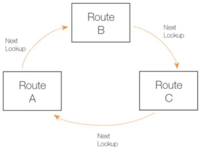
flowchart
graph TD
    A["Route A"] -->|Next Lookup| B["Route B"]
    B -->|Next Lookup| C["Route C"]
    C -->|Next Lookup| A
Figure 4.5. The RLB Round Robin Algorithm
- Destination
This is similar to Round Robin but provides "stickiness" so that unique destination IP addresses always get the same route from a lookup. The importance of this is that it means that a particular destination application can see all traffic coming from the same source IP address.
- Spillover
Spillover is not similar to the previous algorithms. With spillover, the first matching route's interface is repeatedly used until the Spillover Limits of that route's interface are continuously exceeded for the Hold Timer number of seconds.
Once this happens, the next matching route is then chosen. The Spillover Limits for an interface are set in the RLB Algorithm Settings along with the Hold Timer number of seconds (the default is 30 seconds) for the interface.
When the traffic passing through the original route's interface falls below the Spillover Limits continuously for the Hold Timer number of seconds, route lookups will then revert back to the original route and its associated interface.
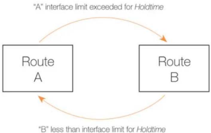
flowchart
graph TD
    A["Route A"] -->|“A” interface limit exceeded for Holdtime| B["Route B"]
    B -->|“B” less than interface limit for Holdtime| A
Figure 4.6. The RLB Spillover Algorithm
Spillover Limits are set separately for ingoing and outgoing traffic with only one of these typically being specified. If both are specified then only one of them needs to be exceeded continuously for Hold Timer seconds for the next matching route to be chosen. The units of the limits, such as Mbps, can be selected to simplify specification of the values.
Using Route Metrics with Round Robin
An individual route has a metric associated with it, with the default metric value being zero.
With the Round Robin and the associated Destination algorithms, the metric value can be set differently on matching routes to create a bias towards the routes with lower metrics. Routes with lower metrics will be chosen more frequently than those with higher metrics and the proportion of usage will be based on the relative differences between the metrics of matching routes.
In a scenario with two ISPs, if the requirement is that the bulk of traffic passes through one of the ISPs then this can be achieved by enabling RLB and setting a low metric on the route to the favoured ISP. A relatively higher metric is then set on the route to the other ISP.
Using Route Metrics with Spillover
When using the Spillover algorithm, a number of points should be noted regarding metrics and the way alternative routes are chosen:
• Route metrics should always be set.
With spillover, NetDefendOS always chooses the route in the matching routes list that has the lowest metric. The algorithm is not intended to be used with routes having the same metric so the administrator should set different metrics for all the routes to which spillover applies.
Metrics determine a clear ordering for which route should be chosen next after the interface traffic limits for the chosen route have been exceeded.
• There can be many alternative routes.
Several alternative routes can be set up, each with their own interface limits and each with a
different metric. The route with the lowest metric is chosen first and when that route's interface limits are exceeded, the route with the next highest metric is then chosen.
When that new route's interface limits are also exceeded then the route with the next highest metric is taken and so on. As soon as any route with a lower metric falls below its interface limit for its Hold Timer number of seconds, then it reverts to being the chosen route.
• If there is no alternative route, the route does not change.
If the spillover limit is reached but all alternative routes have also reached their limit then the route will not change.
The Requirement for Matching IP Ranges
As explained above, when RLB is assembling a list of matching routes from a routing table, the routes it selects must have the same range. Balancing between routes will not take place if their ranges are not exactly the same.
For instance, if one matching route has an IP address range of 10.4.16.0/24 and there is a second matching route with an address range 10.4.16.0/16 (which is a range that includes 10.4.16.0/24) then RLB will not take place between these routes. The ranges are not exactly the same so RLB will treat the routes as being different.
It should also be remembered that route lookup will select the route that has the narrowest range that matches the destination IP address used in the lookup. In the above example, 10.4.16.0/24 may be chosen over 10.4.16.0/16 because the range is narrower with 10.4.16.0/24 for an IP address they both contain.
RLB Resets
There are two occasions when all RLB algorithms will reset to their initial state:
• After NetDefendOS reconfiguration.
• After a high availability failover.
In both these cases, the chosen route will revert to the one selected when the algorithms began operation.
RLB Limitations
It should be noted that the selection of different alternate routes occurs only when the route lookup is done and it is based on the algorithm being used with the routing table used for the lookup and the algorithm's state.
RLB cannot know how much data traffic will be related to each lookup. The purpose of RLB is to be able to spread route lookups across alternatives on the assumption that each lookup will relate to a connection carrying some assumed amount of traffic.
An RLB Scenario
Below, is an illustration which shows a typical scenario where RLB might be used. Here, there is a group of clients on a network connected via the LAN interface of the D-Link firewall and these will access the Internet.
Internet access is available from either one of two ISPs, whose gateways GW1 GW2 are connected to the firewall interfaces WAN1 and WAN2. RLB will be used to balance the connections between the two ISPs.
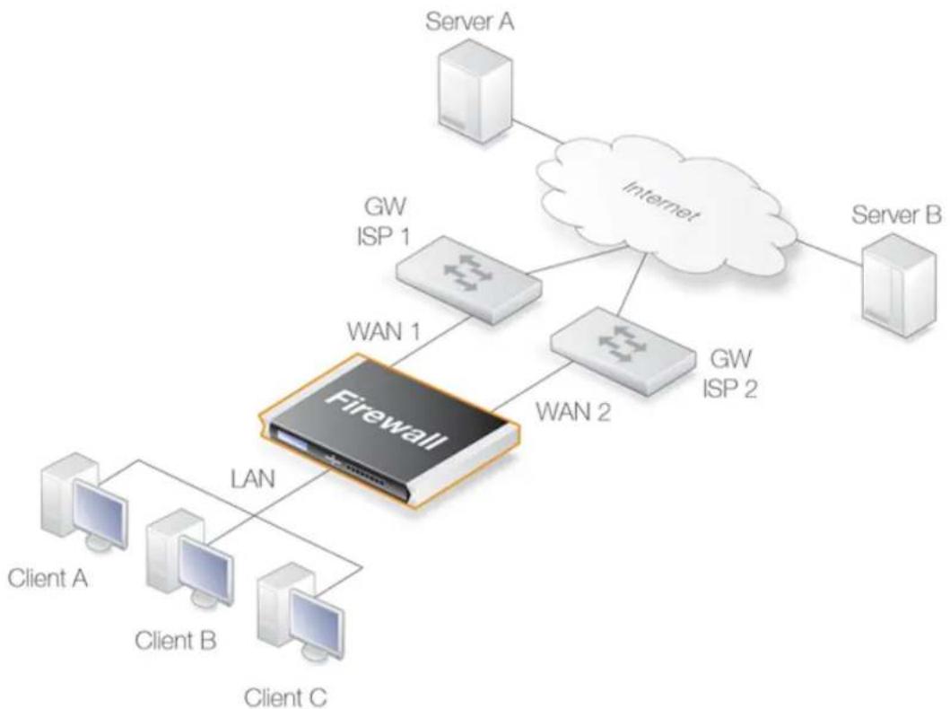
flowchart
graph TD
    A["Server A"] --> B["Internet"]
    C["Server B"] --> B
    D["Client A"] --> E["Client B"]
    F["Client C"] --> E
    G["Client A"] --> H["Client B"]
    I["Client C"] --> H
    J["Client A"] --> K["Client B"]
    L["Client C"] --> K
    M["Client A"] --> N["Client B"]
    O["Client C"] --> N
    P["WAN 1"] --> Q["Firewall"]
    R["WAN 2"] --> Q
    Q --> S["IP 1"]
    Q --> T["IP 2"]
    U["GW ISP 1"] --> V["Cloud"]
    W["GW ISP 2"] --> X["Cloud"]
Figure 4.7. A Route Load Balancing Scenario
We first need to define two routes to these two ISPs in the main routing table as shown below:
| Route No. Interface Destination Gateway Metric | |||
| 1 WAN1 all-nets GW1 100 | |||
| 2 WAN2 all-nets GW2 100 |
We will not use the spillover algorithm in this example so the routing metric for both routes should be the same, in this case a value of 100 is selected.
By using the Destination RLB algorithm we can ensure that clients communicate with a particular server using the same route and therefore the same source IP address. If NAT was being used for the client communication, the IP address seen by the server would be WAN1 or WAN2.
In order to flow, any traffic requires both a route and an allowing IP rule set entry. The following rules will allow traffic to flow to either ISP and will NAT the traffic using the external IP addresses of interfaces WAN1 and WAN2.
| Rule No. | Action | Src Interface | Src Network | Dest Interface | Dest Network | Service |
| 1 | Allow/NAT | lan | lannet | WAN1 | all-nets | all_services |
| 1 | Allow/NAT | lan | lannet | WAN2 | all-nets | all_services |
The service all_services is used in the above IP rule set entries but this should be further narrowed to a specific service or service group that covers specific protocols.
Example 4.9. Setting Up RLB
In this example, the details of the RLB scenario described above will be implemented. The assumption is made that the various IP address book objects needed have already been defined.
The IP objects WAN1 and WAN2 represent the interfaces that connect to the two ISPs and the IP objects GW1 and GW2 represent the IP addresses of the gateway routers at the two ISPs.
Step 1. Set up the routes in the main routing table
Step 2. Create an RLB Instance object
A Route Load Balancing Instance object is now created which uses the Destination algorithm will be selected to achieve stickiness so the server always sees the same source IP address (WAN1 or WAN2) from a single client.
Command-Line Interface
gw-world:/> add RouteBalancingInstance main Algorithm=Destination
Web Interface
- Go to: Network > Routing > Instances > Add > Route Balancing Instance
-
The route balancing instance dialog will appear. Now select:
-
Routing Table: main
- Algorithm: Destination
- Click OK
Step 3. Create IP rule set entries to allow traffic to flow
Lastly, IP rule set entries need to be created that allow the traffic to flow. The detailed steps for this are not included here but the created rules would follow the pattern described above.
RLB with VPN
When using RLB with VPN, a number of issues need to be overcome.
If we were to try and use RLB to balance traffic between two IPsec tunnels, the problem that arises is that the Remote Endpoint for any two IPsec tunnels in NetDefendOS must be different. The solutions to this issue are as follows:
- Use two ISPs, with one tunnel connecting through one ISP and the other tunnel connecting through the other ISP. RLB can then be applied as normal with the two tunnels.
In order to get the second tunnel to function in this case, it is necessary to add a single host route in the main routing table that points to the secondary ISPs interface and with the secondary ISPs gateway.
This solution has the advantage of providing redundancy should one ISP link fail.
- Use VPN with one tunnel that is IPsec based and another tunnel that is uses a different protocol.
If both tunnels must be, for example, IPsec connects, it is possible to wrap IPsec in a GRE tunnel (in other words, the IPsec tunnel is carried by a GRE tunnel). GRE is a simple tunneling protocol without encryption and therefore involves a minimum of extra overhead. See Section 3.4.7, "GRE Tunnels" for more about this topic.
4.5. Active-Active Setup
Overview
NetDefendOS provides the ability to create an active-active setup where a set of D-Link firewalls provide connection both load-sharing and redundancy. Consider the illustration below which shows connections between an internal client and the Internet.
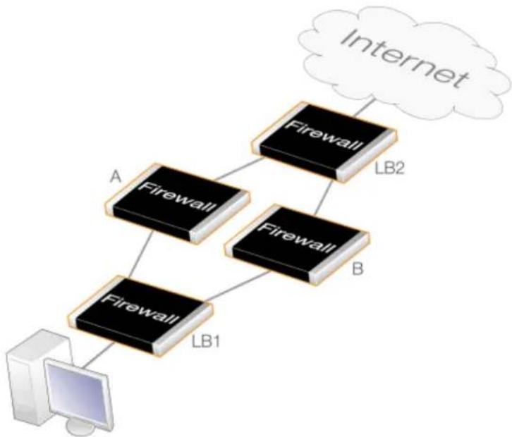
flowchart
graph TD
    A["Firewall"] -->|LB1| B["Computer"]
    A -->|LB2| C["Firewall"]
    C --> D["Internet"]
Figure 4.8. Active-Active Setup
Here, there are 4 different D-Link firewalls. The firewalls LB1 and LB2 balance the internal and external connection load between the firewalls A and B using route load balancing. In addition, route failover ensures that A and B provide redundancy for each other should one of them fail.
Summary of Setup Steps
The following is a summary of the setup steps for the different firewalls. It is assumed that all 4 are identical hardware models and they all have three Ethernet interfaces called if1, if2 and if3.
1. Setup for firewall LB1
LB1 will load balance connections to the Internet from the client between the firewalls A and B. Connections coming from the other direction, originating from the Internet, will be treated normally.
The IP addresses along with the interface names for LB1 are shown in the diagram below.
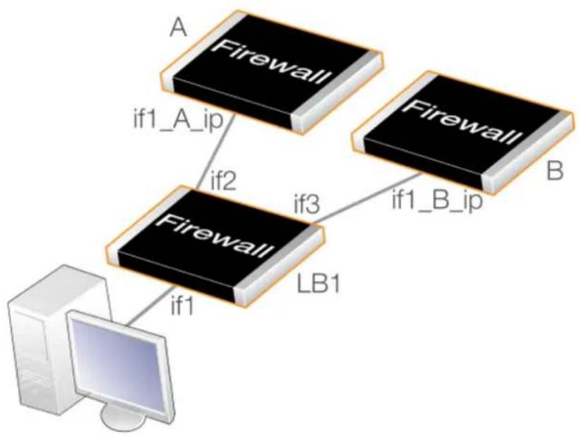
flowchart
graph TD
    A["A Firewall"] -->|if1_A_ip| B["Firewall"]
    B -->|if2| A
    B -->|if3| LB1["LB1"]
    LB1 -->|if1_B_ip| B
    LB1 -->|if1| C["Computer"]
Figure 4.9. Active-Active Load Balancing
- In the address book, create IP address objects for the connecting interfaces on firewalls A and B. Assume that these are called if1_ip_A and if1_ip_B.
- Create a route in the main routing table with all-nets as the network, if2 as the interface and if1_ip_A as the gateway address. This is the route to firewall A.
Configuring routes is described in Section 4.2.2, "Configuring Static Routes".
- Enable the Monitor property for this new route, as well as the properties Monitor Interface Link Status and Monitor Gateway Using ARP properties. This ensures that the route will be disabled should firewall A become unresponsive.
Route monitoring is described further in Section 4.2.3, "Route Failover".
- Create another route in the main routing table with all-nets as the network, if3 as the interface and if1_ip_B as the gateway address. This is the route to firewall B.
- Ensure that the Monitor property for this second route is also enabled along with the properties Monitor Interface Link Status and Monitor Gateway Using ARP. This ensures that the route will be disabled should firewall B become unresponsive.
- Create a Route Balancing Instance for the main routing table, choosing the appropriate distribution method. This method will be either Round Robin or Destination. The Destination method ensures that client connections to the same destination IP address are routed through the same interface (and therefore the same choice from firewall A or B).
Configuring route balancing instances is described further in Section 4.4, "Route Load Balancing".
- It is usually good practice to also create 2 routes that route the address if1_ip_A on the interface if2 and the address if1_ip_B on the interface if3. Using ICMP to ping the firewalls will require this. Without these routes, route load balancing will be applied to all connections to firewalls A and B.
All the routes created for LB1 are summarized in the table below:
| Network Interface Gateway | ||
| all-nets if2 if1_A_ip | ||
| all-nets if3 if1_B_ip | ||
| if1_A_ip if2 | ||
| if1_B_ip if3 |
2. Setup for firewall LB2
LB2 will load balance connections from the Internet to the client between the firewalls A and B. Connections coming from the other direction, originating from the client, will be treated normally.
The setup steps will be the same as for LB1 but in the reverse direction.
3. Setup for firewalls A and B
A and B will be set up like normal configurations and will have the IP rule sets and other processing policies for the traffic. They will duplicate each other except for the IP addresses of Ethernet interfaces.

Note: Increasing fault-tolerance using HA clusters
In the above example, the firewalls LB1 and LB2 represent a potential single point of failure in this setup. However, either or both could be made a NetDefendOS high availability cluster to eliminate this.
4.6. Virtual Routing
4.6.1. Overview
Virtual Routing is a NetDefendOS feature that allows the creation of multiple, logically separated virtual systems within NetDefendOS, each with its own routing table. These systems can behave as physically separated D-Link firewalls and almost everything that can be done with separate firewalls can be done with them, including dynamic routing with OSPF. Virtual systems are sometimes also referred to as Virtual Routers.
The NetDefendOS components involved in creating virtual routing are:
- Separate routing tables for each virtual system.
- Per-interface policy-based routing table membership to make interface IP addresses reachable only via a particular routing table. This association can be made explicitly by linking an interface with a specific routing table.
- Pairs of loopback interfaces can be used for communication between virtual systems if required (see also Section 3.4.9, "Loopback Interfaces").
There are two ways of associating a specific routing table with a specific interface:
- Using Routing Rules
Routing Rules can be defined so that all traffic on a particular interface are subject to a particular routing table.
• Specifying a Routing Table for an Interface
It is possible to associate an interface directly with a specific routing table. This is known as the interface's routing table membership. This option is part an interface's virtual routing options.
This is the preferred way of implementing a virtual router. The interface might be physical or it could be a virtual LAN (VLAN).
To ensure that a routing table does not use any other tables in the route lookup process, the Ordering parameter of the table should be set to Only. This is discussed further in Section 4.3, "Policy-based Routing".
4.6.2. A Simple Scenario
Consider a single D-Link firewall connected to two external ISPs, ISP1 and ISP2. ISP1 provides Internet connection to the internal network for Department A and connects to the firewall via the physical interface If1.
ISP2 provides Internet connection to the internal network for Department B and connects via the physical interface If2. For administration purposes it is decided that the D-Link firewall is to be divided into 2 virtual systems, one for each ISP.
This is done by creating two dedicated routing tables. pbr1 is created to handle traffic for ISP1 and Department A. pbr2 is created to handle traffic for ISP2 and Department B. This arrangement is illustrated in the diagram below.
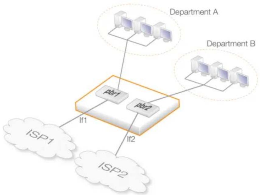
flowchart
graph TD
    A["Department A"] --> B["Router"]
    C["Department B"] --> B
    B --> D["ISP1"]
    B --> E["ISP2"]
    D --> F["If1"]
    E --> G["If2"]
    F --> H["pbr1"]
    G --> I["pbr2"]
Figure 4.10. Virtual Routing
When the administrator configures this in NetDefendOS, interface If1 is made a member of routing table pbr1 but not pbr2. In other words, If1 is explicitly associated with pbr1. Conversely, interface If2 is made a member of pbr2 but not pbr1. It is this interface membership which determines which routing table is used and this keeps the two sets of traffic totally separated.

Tip: Creating dedicated routing tables is best
In this example, the main routing table could have been used as one of the two routing tables. However, it is usually better and clearer to instead create new, dedicated routing tables with appropriate names for each separated portion of data traffic.
Reusing Private IP Addresses
An advantage of using separate routing tables on different interfaces is that internal, private IP address ranges can be reused on different virtual systems. For example, Department A and Department B could both use the internal network 192.168.0.0/24.
Since route lookup is done in completely separate routing tables, there are no conflicts.
VPN Tunnels are Interfaces
VPN tunnels are also considered to be interfaces in NetDefendOS and can therefore also be associated with their own routing tables just as physical interfaces can.
This means that VPN tunnels can be logically separated from each other within NetDefendOS.
Using Loopback Interfaces
In this simple example, loopback interfaces were not used since there is no requirement for
communication between the virtual systems. For example, Department A does not need to communicate with Department B. If communication between them is needed then an appropriate loopback interface pair would have to be defined to allow this.
After we define a loopback interface, all traffic sent to that interface automatically appears as being received on another interface.
4.6.3. The Disadvantage of Routing Rules
Using Routing Rules can solve many of the problems that virtual routing can but complex configurations can become unwieldy for such rules. Consider a single D-Link firewall being used as a firewall for two organizations, both using the same IP span.
In this case, two separate routing tables could be used, one for each organization as shown below.
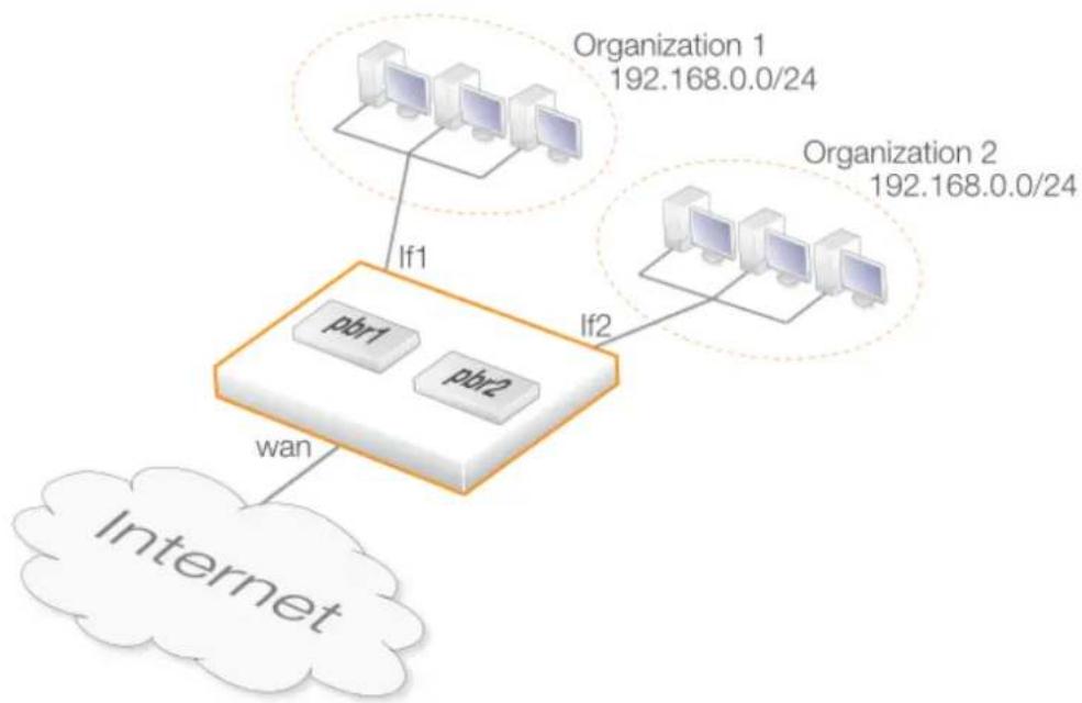
flowchart
graph TD
    A["Router"] -->|If1| B["Internet"]
    C["Router 1"] -->|If2| D["Router"]
    E["Router 2"] -->|If2| F["Router"]
    B --> G["paR1"]
    B --> H["paR2"]
    style B fill:#f9f,stroke:#333
    style C fill:#ccf,stroke:#333
    style E fill:#cfc,stroke:#333
    style F fill:#fcc,stroke:#333
Figure 4.11. The Disadvantage of Routing Rules
Two routing tables pbr1 and pbr2 are first defined for this scenario. Their contents are listed below:
Routing Table pbr1
| Route # Interface Network Gateway | |||
| 1 wan all-nets wan_gw | |||
| 2 If1 | 192.168.0.0/24 | ||
Routing Table pbr2
| Route # Interface Network Gateway | |||
| 1 wan all-nets wan_gw | |||
| 2 If2 192.168.0.0/24 |
Getting traffic from each network to and from the Internet is straightforward. Assuming only outbound traffic, it requires only two Routing Rule objects. Assuming that each organization has a public IPv4 address which maps to servers on the respective networks then outbound as well as inbound traffic can be handled with the following four routing rules:
| Route # | Name | Source If | Source Net | Dest Net | Fwd Table | Ret Table |
| 1 | org1-in | wan | all-nets | pubip-org1 | pbr1 | pbr1 |
| 2 | org1-out | lf1 | all-nets | all-nets | pbr1 | pbr1 |
| 3 | org2-in | wan | all-nets | pubip-org2 | pbr2 | pbr2 |
| 4 | org2-out | lf2 | all-nets | all-nets | pbr2 | pbr2 |
This works if the two organizations do not need to communicate with each other. If they do, the following two additional routing rules are also needed and are placed before the four above.
| Route # | Name | Source if | Source Net | Dest Net | Fwd Table | Ret Table |
| 1 | org1-org2 | lf11 | all-nets | pubip-org2 | pbr1 | pbr2 |
| 2 | org2-org1 | lf2 | all-nets | pubip-org1 | pbr2 | pbr1 |
With two organizations, two routing rules are enough to allow them to communicate. However, with three organizations, six are needed; with four, twelve are needed; with five, twenty are needed as so on. The numbers continue with an all-to-all mapping of 30, 42, 56 rules and the administration task soon becomes unmanageable.
The Advantage of Virtual Routing
Virtual routing can eliminate the all-to-all mapping required with routing rules by using interface routing table membership instead of routing rules. This reduces the complexity by creating 3 virtual systems which are represented by the router symbols in the diagram below.
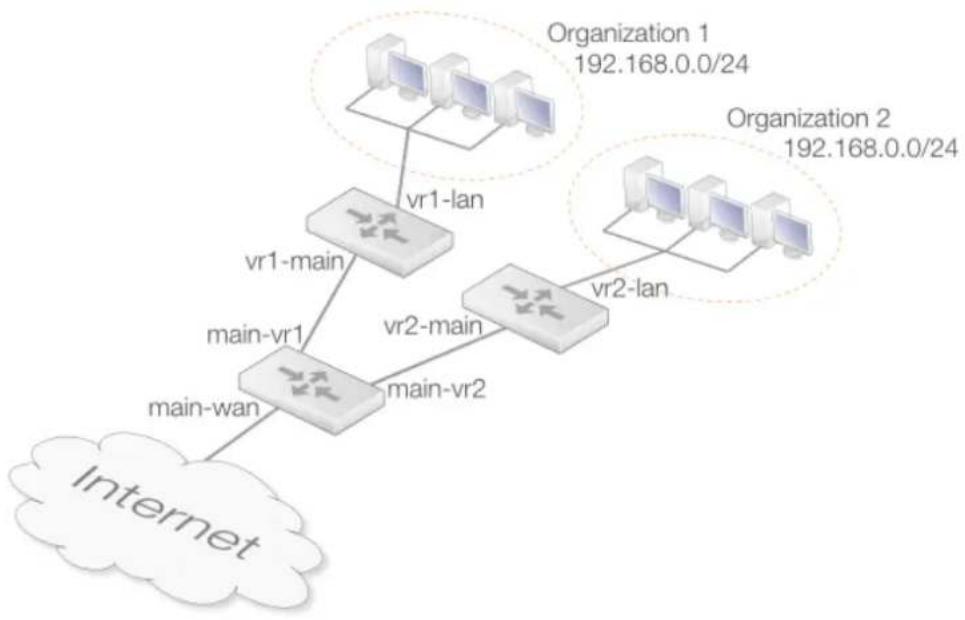
flowchart
graph TD
    A["Internet"] --> B["Main-wan"]
    B --> C["main-vr1"]
    C --> D["Main-vr1-main"]
    D --> E["vr1-lan"]
    E --> F["Organization 1 192.168.0.0/24"]
    D --> G["vr2-main"]
    G --> H["Main-vr2"]
    H --> I["vr2-lan"]
    I --> J["Organization 2 192.168.0.0/24"]
Figure 4.12. The Advantage of Virtual Routing
Here, each organization gets a virtual system of its own. These connect to the main routing table using pairs of loopback interfaces. The routing tables would have the following entries:
Routing Table main
| Route # Interface Network Gateway | |||
| 1 main-wan all-nets wan_gw | |||
| 2 main-vs1 pubip-vs1 | |||
| 3 main-vs2 pubip-vs2 | |||
Routing Table vs1
| Route # Interface Network Gateway | |||
| 1 vs1-main all-nets | |||
| 2 vs1-lan 192.168.0.0/24 | |||
Routing Table vs2
| Route # Interface Network Gateway | ||
| 1 vs2-main all-nets | ||
| 2 vs2-lan 192.168.0.0/24 |
Ethernet Interfaces
| Interface # Name IP Address Routing Table | |||
| 1 main-wan ip_main-wan main | |||
| 2 vs1-lan 192.168.0.1 vs1 | |||
| 3 vs2-lan 192.168.0.254 | vs2 |
Loopback Interfaces
| # | Name | IP Address | Loop to | Routing Table |
| 1 main-vs1 | ip_main-wan | vs1-main | main | |
| 2 vs1-main | pubip-vs1 | main-vs1 | vs1 | |
| 3 main-vs2 | ip_main-wan | vs2-main | main | |
| 4 vs2-main | pubip-vs2 | main-vs2 | vs2 |
For each connection between a pair of virtual systems, a pair of loopback interfaces is required, one for each system. When traffic is sent through main-vs1, it arrives on vs1-main. When traffic is sent through vs1-main, it is received on main-vs1. This is exactly the same as with two firewalls and two interfaces, one on each, with a connection between them.
The Routing Table Membership setting means that if a connection arrives on an interface, it will be routed according to the routing table that the interface is a member of.
Also note how the IPv4 addresses of the internal interfaces of the virtual systems differ. If per-interface routing table membership were not used, the core routes for both IP addresses would be added in both routing tables, leading to 192.168.0.1 being unusable in vs2 (even though it should be usable) and 192.168.0.254 being unusable in vs1. With per-interface routing table membership, interface IP addresses belonging to one virtual system will not interfere with other virtual systems and loopback interfaces are not needed.
The IPv4 addresses of the main-vs1 and main-vs2 interfaces are the same as the IP address of the external interface. They could also have been set to something nonsensical, such as 127.0.0.1. Regular routing would still have worked since loopback interfaces are raw IP interfaces (the ARP protocol is not used over them). However, their IP addresses will be visible to users doing a traceroute from the inside, and also the issue exists of traffic originating from the D-Link firewall itself to the internal networks, such as pings or logging. Such traffic is most often routed according to the main routing table, and will be sourced from the IP address of the nearest interface in the main routing table.
4.6.4. IP Rule Sets with Virtual Routing
The IP rule sets for different virtual systems can be split into separate rule sets using the NetDefendOS feature of creating multiple IP rule sets (see Section 3.6.5, "Multiple IP Rule Sets" for more detail on this feature).
IP rule set entries for different virtual systems need not be split up. They can reside together in a single IP rule set. The benefit of doing this is being able to define "shared" or "global" IP policies that span over several virtual systems. For example, for aggressive "worm" attacks, it may be desirable to drop all communication on ports known to be used by the worm until counter-measures can be put into place. A single Drop entry placed at the top of the rule set can take care of this for all the virtual systems. Using the example of the previous section, this is how the IP rule set might look:
Interface Groups
| # Name Interfaces | ||
| 1 main-vsifs main-vs1, main-vs2 | ||
| 2 main-ifs | main-wan, main-vsifs | |
| 3 vs1-ifs vs1-main, vs1-lan | ||
| 4 vs2-ifs vs2-main, vs2-lan |
IP Rule Set Entries
| # | Name | Action | Source If | Source Net | Dest If | Dest Net | Service |
| IP rule set entries for the "main" virtual system | |||||||
| 1 | main-allowall | Allow | main-ifs | all-nets | Any | all-nets | all_services |
| IP rule set entries for the "vs1" virtual system | |||||||
| 2 | vs1-http-in | Allow/SAT | vs1-ifs | all-nets | pubip-vs1 | all-nets | http SetDest 192.168.0.5 |
| 3 | vs1-http-in | Allow | vs1-main | all-nets | Any | pubip-vs1 | http |
| 4 | vs1-out | Allow/NAT | vs1-int | all-nets | Any | all-nets | all_services |
| IP rule set entries for the "vs2" virtual system | |||||||
| 5 | vs2-smtp-in | Allow/SAT | vs2-main | all-nets | Any | pubip-vs2 | all_services |
| 6 | vs2-smtp-in | Allow | vs2-main | all-nets | Any | pubip-vs2 | smtp |
| 7 | vs2-http-out | Allow/NAT | vs2-int | 192.168.0.4 | vs2-main | all-nets | http |
Note that SAT rules do not need to take into account that there are more organizations connected to the same physical unit. There is no direct connection between them; everything arrives through the same interface, connected to the main routing table. If this was done without virtual routing, the Allow rules would have to be preceded by NAT rules for traffic from other organizations. Care would also have to be taken that such rules were in accordance with the security policy of each organization. Such problems are eliminated with virtual routing.
The source interface filters are very specific. Any is not used as the source interface anywhere, since such a rule would trigger regardless. Consider for instance what would happen if the vs1-http-in rules were to use Any as source interface. They would trigger as soon as packets destined to pubip-vs1 were received on main-ext. The destination address would be rewritten to 192.168.0.5, and passed on using the main routing table. The main routing table would not know what to do with 192.168.0.5 and pass it back out to the default gateway outside the D-Link firewall.
If the same naming scheme as shown in this example is used, making sure the source interfaces are correct can be done quickly. All the rules concerning the main system have source interfaces beginning with "main-". All those concerning vs1 have source interfaces beginning with "vs1-", and so on.
The destination interface filters, however, do not need to be as specific as the source interface filters. The possible destinations are limited by the routing tables used. If the vs1 table only includes routes through vs1- interfaces, Any filters can only mean "through other interfaces in the same virtual system". It may however be sound practice to write tighter destination interface filters in case an error occurs elsewhere in the configuration. In this example, rule 1 might use main-ifs, rule 4 might use vs1-main. The SAT and corresponding Allow rules however are already fairly tight in that they only concern one single destination IP address.
4.6.5. Multiple IP rule sets
An alternative approach to having all the IP policies for different virtual systems in one rule set is to make use of Multiple IP rule sets.
Although all scanning of IP rule sets begins in the main rule set, it is possible to create an entry in the main set whose action is Goto so that scanning continues in another separate, named rule set. These extra rule sets can be defined as needed and one rule set can be created for each virtual system and its corresponding routing table.
More details on this subject can be found in Section 3.6.5, "Multiple IP Rule Sets".
4.6.6. Trouble Shooting
When setting up virtual routing, the following steps can help with troubleshooting any problems.
• Make sure that the source interface filters are correct
- Double check interface PBR table membership, for all types of interfaces and tunnels.
- Use "ping -p
- Use "ping -r
- Use "arpsnoop -v
- Use "route
- Use "route -lookup
way expected in a given virtual system. (Hint: "-lookup" may be shortened to "-I".)
- Use "conn -v" to view verbose information about open connections. Both ends of a connection will be shown; before and after address translation. Also, the routing tables used in the forward and return direction will be shown.
- Enable logging and read the logs. In each virtual system, a separate rule decision is made, and a separate connection is established.
4.7. OSPF
The feature called Dynamic Routing is implemented in NetDefendOS using the Open Shortest Path First (OSPF) architecture.

Note: OSPF is not available on all NetDefend models
The OSPF feature is not available on the DFL-260E.
This section begins by looking generally at what dynamic routing is and how it can be implemented. It then goes on to look at how OSPF can provide dynamic routing followed by a description of how a simple OSPF network can be set up.
4.7.1. Dynamic Routing
Before looking at OSPF in detail this section will discuss generally the concept of Dynamic routing and what type of dynamic routing OSPF provides. It introduces important concepts in dynamic routing and in OSPF.
Differences to Static Routing
Dynamic routing is different to static routing in that a routing network device, such as a firewall, can adapt to changes of network topology automatically.
Dynamic routing involves first learning about all the directly connected networks and then getting further routing information from other connected routers specifying which networks they are connected to. All this routing information is then processed and the most suitable routes for both locally connected and remotely connected destinations are added into local routing tables.
Dynamic routing responds to routing updates dynamically but has some disadvantages in that it can be more susceptible to certain problems such as routing loops. One of two types of algorithms are generally used to implement the dynamic routing mechanism:
• A Distance Vector (DV) algorithm.
• A Link State (LS) algorithm.
How a router decides the optimal or "best" route and shares updated information with other routers depends on the type of algorithm used. The two algorithm types will be discussed next.
Distance Vector Algorithms
A Distance vector algorithm is a decentralized routing algorithm that computes the best path in a distributed way.
Each router in a network computes the "costs" of its own attached links, and shares routing information only with its neighboring routers. Each router determines the least-cost path to a destination by iterative computation and also using information exchanged with its neighbors.
Routing Information Protocol (RIP) is a well-known DV algorithm for router information exchange and operates by sending regular update messages and reflecting routing changes in routing tables. Path determination is based on the "length" of the path which is the number of intermediate routers (also known as "hops") to the destination.
After updating its own routing table, the router immediately begins transmitting its entire routing table to neighboring routers to inform them of changes.
Link State Algorithms
In contrast to DV algorithms, Link State (LS) algorithms enable routers to keep routing tables that reflect the topology of the entire network.
Each router broadcasts its attached links and link costs to all other routers in the network. When a router receives these broadcasts it runs the LS algorithm and calculates its own set of least-cost paths. Any change of the link state will be sent everywhere in the network, so that all routers keep the same routing table information and have a consistent view of the network.
Advantages of Link State Algorithms
Due to the fact that the global link state information is maintained everywhere in a network, LS algorithms, like that used in OSPF, offer a high degree of configuration control and scalability. Changes result in broadcasts of just the updated information to other routers which means faster convergence and less possibility of routing loops. OSPF can also function within a hierarchy, whereas RIP has no knowledge of sub-network addressing.
The OSPF Solution
Open Shortest Path First (OSPF) is a widely used protocol based on an LS algorithm. Dynamic routing is implemented in NetDefendOS using OSPF.
An OSPF enabled router first identifies the routers and sub-networks that are directly connected to it and then broadcasts the information to all the other routers. Each router uses the information it receives to add the OSPF learned routes to its routing table.
With this larger picture, each OSPF router can identify the networks and routers that lead to a given destination IP and therefore the best route. Routers using OSPF then only broadcast updates to inform others of any route changes instead of broadcasting the entire routing table.
OSPF depends on various metrics for path determination, including hops, bandwidth, load and delay. OSPF can also provide a high level of control over the routing process since its parameters can be finely tuned.
A Simple OSPF Scenario
The simple network topology illustrated below provides an excellent example of what OSPF can achieve. Here we have two D-Link firewalls A and B connected together and configured to be in the same OSPF area (the concept of area will be explained later).
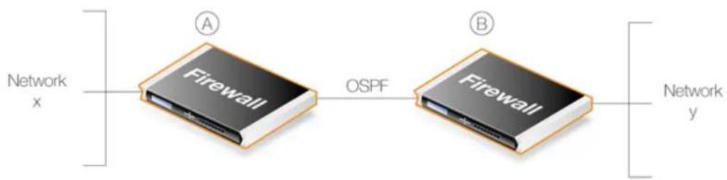
flowchart
graph LR
    A["Firewall"] -->|OSPF| B["Firewall"]
    style A fill:#f9f,stroke:#333
    style B fill:#f9f,stroke:#333
Figure 4.13. A Simple OSPF Scenario
OSPF allows firewall A to know that to reach network Y, traffic needs to be sent to firewall B. Instead of having to manually insert this routing information into the routing tables of A, OSPF allows B's routing table information to be automatically shared with A.
In the same way, OSPF allows firewall B to automatically become aware that network X is attached to firewall A.
Under OSPF, this exchange of routing information is completely automatic.
OSPF Provides Route Redundancy
If we now take the above scenario and add a third firewall called C then we have a situation where all three firewalls are aware, through OSPF, of what networks are attached to the other firewalls. This is illustrated below.
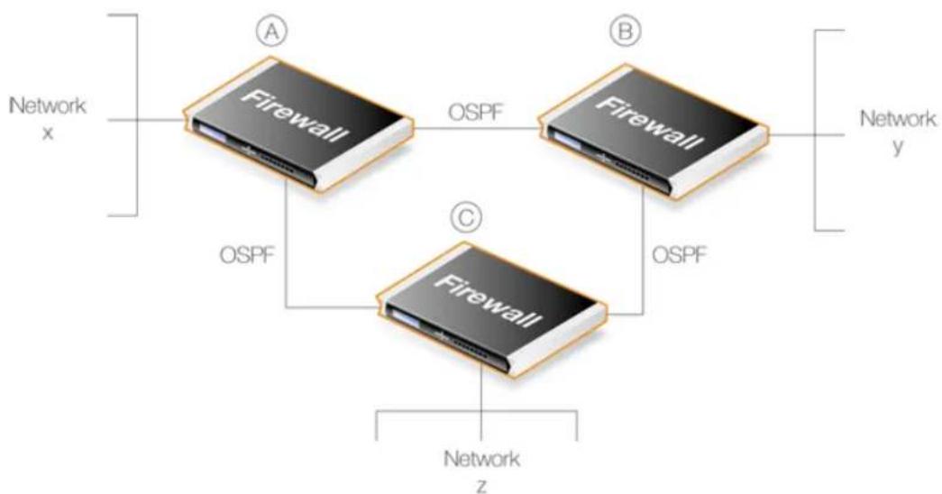
flowchart
graph TD
    A["Firewall"] -->|OSPF| B["Firewall"]
    B -->|OSPF| C["Firewall"]
    C --> D["Network x"]
    C --> E["Network y"]
    C --> F["Network z"]
Figure 4.14. OSPF Providing Route Redundancy
In addition, we now have route redundancy between any two of the firewalls. For example, if the direct link between A and C fails then OSPF allows both firewalls to know immediately that there is an alternate route between them via firewall B.
For instance, traffic from network X which is destined for network Z will be routed automatically through firewall B.
From the administrator's point of view, only the routes for directly connected networks need to be configured on each firewall. OSPF automatically provides the required routing information to find networks connected to other firewalls, even if traffic needs to transit several other firewalls to reach its destination.

Tip: Ring topologies always provide alternate routes
When designing the topology of a network that implements OSPF, arranging D-Link firewalls in a circular ring means that any firewall always has two possible routes to any other. Should any one inter-firewall connection fail, an alternative path always exists.
A Look at Routing Metrics
In discussing dynamic routing and OSPF further, an understanding of Routing Metrics can be useful and a brief explanation is given here.
Routing metrics are the criteria that a routing algorithm will use to compute the "best" route to a destination. A routing protocol relies on one or several metrics to evaluate links across a network and to determine the optimal path. The principal metrics used include:
Path length The sum of the costs associated with each link. A commonly used value for this metric is called "hop count" which is the number of routing devices a packet must pass through when it travels from source to destination.
Item Bandwidth The traffic capacity of a path, rated by "Mbps".
Load The usage of a router. The usage can be evaluated by CPU utilization and throughput.
Delay The time it takes to move a packet from the source to the destination. The time depends on various factors, including bandwidth, load, and the length of the path.
4.7.2. OSPF Concepts
Overview
Open Shortest Path First (OSPF) is a routing protocol developed for IP networks by the Internet Engineering Task Force (IETF). The NetDefendOS OSPF implementation is based upon RFC 2328, with compatibility to RFC 1583.
OSPF functions by routing IP packets based only on the destination IP address found in the IP packet header. IP packets are routed "as is", in other words they are not encapsulated in any further protocol headers as they transit the Autonomous System (AS).
The Autonomous System
The term Autonomous System refers to a single network or group of networks with a single, clearly defined routing policy controlled by a common administrator. It forms the top level of a tree structure which describes the various OSPF components.
In NetDefendOS, an AS corresponds to an OSPF Router object. This must be defined first when setting up OSPF. In most scenarios only one OSPF router is required to be defined and it must be defined separately on each D-Link firewall involved in the OSPF network. This NetDefendOS object is described further in Section 4.7.3.1, "OSPF Router Process".
OSPF is a dynamic routing protocol as it quickly detects topological changes in the AS (such as router interface failures) and calculates new loop-free routes to destinations.
Link-state Routing
OSPF is a form of link-state routing (LS) that sends Link-state Advertisements (LSAs) to all other routers within the same area. Each router maintains a database, known as a Link-state Database, which maps the topology of the autonomous system (AS). Using this database, each router constructs a tree of shortest paths to other routers with itself as the root. This shortest-path tree yields the best route to each destination in the AS.
Authentication.
All OSPF protocol exchanges can, if required, be authenticated. This means that only routers with the correct authentication can join an AS. Different authentication schemes can be used and with NetDefendOS the scheme can be either a passphrase or an MD5 digest.
It is possible to configure separate authentication methods for each AS.
OSPF Areas
An OSPF Area consists of networks and hosts within an AS that have been grouped together. Routers that are only within an area are called internal routers. All interfaces on internal routers are directly connected to networks within the area.
The topology of an area is hidden from the rest of the AS. This information hiding reduces the amount of routing traffic exchanged. Also, routing within the area is determined only by the area's own topology, lending the area protection from bad routing data. An area is a generalization of an IP subnetted network.
In NetDefendOS, areas are defined by OSPF Area objects and are added to the AS which is itself defined by an OSPF Router object. There can be more than one area within an AS so multiple OSPF Area objects could be added to a single OSPF Router. In most cases, one is enough and it should be defined separately on each D-Link firewall which will be part of the OSPF network.
This NetDefendOS object is described further in Section 4.7.3.2, "OSPF Area".
OSPF Area Components
A summary of OSPF components related to an area is given below:
| ABRs | Area Border Routers are routers that have interfaces connected to more than one area. These maintain a separate topological database for each area to which they have an interface. |
| ASBRs Routers that exchange routing information with routers in other Autonomous Systems are called Autonomous System Boundary Routers. They advertise externally learned routes throughout the Autonomous System. | |
| Backbone Areas | All OSPF networks need to have at least the Backbone Area which is the OSPF area with an ID of 0. This is the area that other related areas should be connected to. The backbone ensures routing information is distributed between connected areas. When an area is not directly connected to the backbone it needs a virtual link to it. |
| OSPF networks should be designed by beginning with the backbone. | |
| Stub Areas | Stub areas are areas through which or into which AS external advertisements are not flooded. When an area is configured as a stub area, the router will automatically advertise a default route so that routers in the stub area can reach destinations outside the area. |
| Transit Areas | Transit areas are used to pass traffic from an area that is not directly connected to the backbone area. |
The Designated Router
Each OSPF broadcast network has a single Designated Router (DR) and a single Backup Designated Router. The routers use OSPF Hello messages to elect the DR and BDR for the network based on the priorities advertised by all the routers. If there is already a DR on the network, the router will
accept that one, regardless of its own router priority.
With NetDefendOS, the DR and the BDR are automatically assigned.
Neighbors
Routers that are in the same area become neighbors in that area. Neighbors are elected by the use of Hello messages. These are sent out periodically on each interface using IP multicast. Routers become neighbors as soon as they see themselves listed in a neighbor's Hello message. In this way, a two way communication is guaranteed.
The following Neighbor States are defined:
Down This is the initial state of the neighbor relationship.
Init When a Hello message is received from a neighbor, but does NOT include the Router ID of the firewall in it, the neighbor will be placed in the Init state.
As soon as the neighbor in question receives a Hello message it will know the sending router's Router ID and will send a Hello message with that included. The state of the neighbors will change to the 2-way state.
2-Way In this state the communication between the router and the neighbor is bidirectional.
On Point-to-Point and Point-to-Multipoint OSPF interfaces, the state will be changed to Full. On Broadcast interfaces, only the DR/BDR will advance to the Full state with their neighbors, all the remaining neighbors will remain in the 2-Way state.
ExStart Preparing to build adjacency.
Exchange Routers are exchanging Data Descriptors.
Loading Routers are exchanging LSAs.
Full This is the normal state of an adjacency between a router and the DR/BDR.
Aggregates
OSPF Aggregation is used to combine groups of routes with common addresses into a single entry in the routing table. This is commonly used to minimize the routing table.
To set this feature up in NetDefendOS, see Section 4.7.3.5, "OSPF Aggregates".
Virtual Links
Virtual links are used for the following scenarios:
A. Linking an area that does not have a direct connection to the backbone area.
B. Linking backbone areas when the backbone is partitioned.
The two uses are discussed next.
A. Linking areas without direct connection to the backbone
The backbone area always needs to be the center of all other areas. In some rare cases where it is impossible to have an area physically connected to the backbone, a Virtual Link is used. Virtual
links can provide an area with a logical path to the backbone area.
This virtual link is established between two Area Border Routers (ABRs) that are on one common area, with one of the ABRs connected to the backbone area. In the example below two routers are connected to the same area (Area 1) but just one of them, fw1, is connected physically to the backbone area.
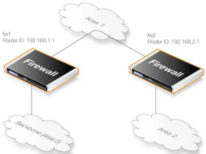
flowchart
graph TD
    A["Firewall"] -->|fw1 Router ID: 192.168.1.1| B["Area 1"]
    C["Firewall"] -->|fw2 Router ID: 192.168.2.1| D["Area 2"]
    E["Backbone (Area 0)"] --> A
    E --> C
Figure 4.15. Virtual Links Connecting Areas
In the above example, a Virtual Link is configured between fw1 and fw2 on Area 1 as it is used as the transit area. In this configuration only the Router ID has to be configured. The diagram shows that fw2 needs to have a Virtual Link to fw1 with Router ID 192.168.1.1 and vice versa. These virtual links need to be configured in Area 1.
B. Linking a Partitioned Backbone
OSPF allows for linking a partitioned backbone using a virtual link. The virtual link should be configured between two separate ABRs that touch the backbone from each side and have a common area in between.
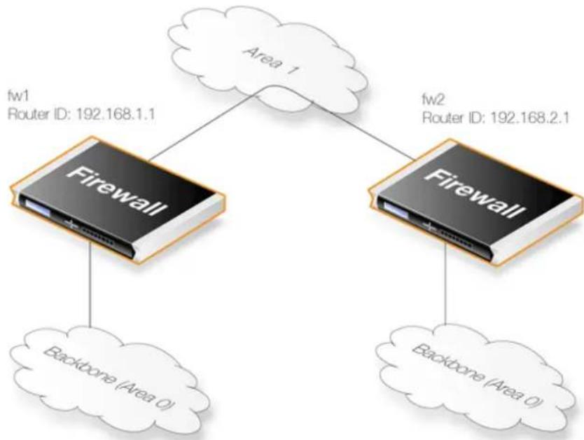
flowchart
graph TD
    A["Firewall"] --> B["Backbone (Area 0)"]
    C["Firewall"] --> D["Backbone (Area 0)"]
    E["Area 1"] --> F["Router ID: 192.168.1.1"]
    G["Area 1"] --> H["Router ID: 192.168.2.1"]
Figure 4.16. Virtual Links with Partitioned Backbone
The virtual link is configured between fw1 and fw2 on Area 1 as it is used as the transit area. In the configuration, only the Router ID has to be configured, as in the example above show fw2 need to have a virtual link to fw1 with the Router ID 192.168.1.1 and vice versa. These virtual links need to be configured in Area 1.
To set this feature up in NetDefendOS, see Section 4.7.3.6, "OSPF VLinks".
OSPF High Availability Support
There are some limitations in High Availability support for OSPF that should be noted:
Both the active and the inactive part of an HA cluster will run separate OSPF processes, although the inactive part will make sure that it is not the preferred choice for routing. The HA master and slave will not form adjacency with each other and are not allowed to become DR/BDR on broadcast networks. This is done by forcing the router priority to 0.
For OSPF HA support to work correctly, the D-Link firewall needs to have a broadcast interface with at least ONE neighbor for ALL areas that the firewall is attached to. In essence, the inactive part of the cluster needs a neighbor to get the link state database from.
It should also be noted that is not possible to put an HA cluster on the same broadcast network without any other neighbors (they will not form adjacency with each other because of the router priority 0). However, it may be possible, depending on the scenario, to set up a point to point link between them instead. Special care must also be taken when setting up a virtual link to an firewall in an HA cluster. The endpoint setting up a link to the HA firewall must setup 3 separate links: one to the shared, one to the master and one to the slave router id of the firewall.
Using OSPF with NetDefendOS
When using OSPF with NetDefendOS, the scenario will be that we have two or more D-Link firewalls connected together in some way. OSPF allows any of these firewall to be able to correctly route traffic to a destination network connected to another firewall without having a
route in its routing tables for the destination.
The key aspect of an OSPF setup is that connected firewalls will share the information in their routing tables so that traffic entering an interface on one of the firewalls can be automatically routed so that it exits the interface on another gateway which is attached to the correct destination network.
Another important aspect is that the firewalls monitor the connections between each other and route traffic by an alternate connection if one is available. A network topology can therefore be designed to be fault tolerant. If a connection between two firewalls fails then any alternate route that also reaches the destination will be used.
4.7.3. OSPF Components
This section looks at the NetDefendOS objects that need to be configured for OSPF routing. Defining these objects creates the OSPF network. The objects should be defined on each D-Link firewall that is part of the OSPF network and should describe the same network.
An illustration of the relationship between NetDefendOS OSPF objects is shown below.
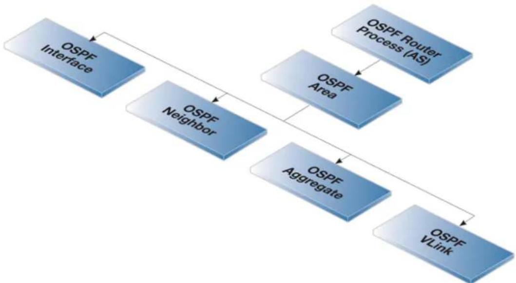
flowchart
graph TD
    A["OSPF Interface"] --> B["OSPF Neighbor"]
    B --> C["OSPF Area"]
    C --> D["OSPF Aggregate"]
    D --> E["OSPF VLink"]
    F["OSPF Router Process (AS)"] --> C
Figure 4.17. NetDefendOS OSPF Objects
4.7.3.1. OSPF Router Process
This object defines the autonomous system (AS) which is the top level of the OSPF network. A similar Router Process object should be defined on each firewall which is part of the OSPF network.
General Parameters
Name
Specifies a symbolic name for the OSPF AS.
Router ID
Specifies the IP address that is used to identify the router in a AS. If no Router ID is configured, the firewall computes the Router ID based on the highest IP address of any interface
| participating in the OSPF AS. | |
| Private Router ID | This is used in an HA cluster and is the ID for this firewall and not the cluster. |
| NoteWhen running OSPF on a HA Cluster there is a need for a private master and private slave Router ID as well as the shared Router ID. | |
| Reference Bandwidth | Set the reference bandwidth that is used when calculating the default interface cost for routes.If bandwidth is used instead of specifying a metric on an OSPF Interface, the cost is calculated using the following formula:cost = reference bandwidth / bandwidth |
| RFC 1583 Compatibility | Enable this if the D-Link firewall will be used in an environment that consists of routers that only support RFC 1583. |
Debug
The debug options provides a troubleshooting tool by enabling the generation of additional OSPF log events. These are described more fully in Section 4.7.7, "OSPF Troubleshooting".
Authentication
The primary purpose of OSPF authentication is to make sure that the correct OSPF router processes are talking to each and it is therefore mostly used when there are multiple OSPF AS'. OSPF supports the following authentication options:
No (null) authentication No authentication is used for OSPF protocol exchanges.
Passphrase A simple password is used to authenticate all the OSPF protocol exchanges.
MD5 Digest MD5 authentication consists of a key ID and 128-bit key. When MD5 digest is used the specified key is used to produce the 128-bit MD5 digest.
This does NOT mean that the OSPF packets are encrypted. If the OSPF traffic needs to be encrypted then they must be sent using a VPN. For example, using IPsec. Sending OSPF packets through an IPsec tunnel is discussed further in Section 4.7.5, "Setting Up OSPF".

Note: Authentication must be the same on all routers
If a passphrase or MD5 authentication is configured for OSPF, the passphrase or authentication key must be the same on all OSPF Routers in that Autonomous System.
In other words, the OSPF authentication method must be replicated on all firewalls.
Advanced
Time Settings
SPF Hold Time
Specifies the minimum time, in seconds, between two SPF calculations. The default time is 10 seconds. A value of 0 means that there is no delay. Note however that SPF can potentially be a CPU demanding process, so in a big network it may not be a good idea to run it too frequently.
SPF Delay Time
Specifies the delay time, in seconds, between when OSPF receives a topology change and when it starts a SPF calculation. The default time is 5 seconds. A value of 0 means that there is no delay. Note however that SPF can potentially be a CPU demanding process, so in a big network it might not be a good idea to run it too often.
LSA Group Pacing
This specifies the time in seconds at which interval the OSPF LSAs are collected into a group and refreshed. It is more optimal to group many LSAs and process them at the same time, instead of running them one and one.
Routes Hold Time
This specifies the time in seconds that the routing table will be kept unchanged after a reconfiguration of OSPF entries or a HA failover.
Memory Settings
Memory Max Usage
Maximum amount in Kilobytes of RAM that the OSPF AS process are allowed to use, if no value is specified the default is 1% of installed RAM. Specifying 0 indicates that the OSPF AS process is allowed to use all available ram in the firewall.
4.7.3.2. OSPF Area
The Autonomous System (AS) is divided into smaller parts called an Area, this section explains how to configure areas. An area collects together OSPF interfaces, neighbors, aggregates and virtual links.
An OSPF Area is a child of the OSPF Router Process and there can be many area objects defined under a single router process. In most simple networking scenarios, a single area is sufficient. Like the router process object, a similar area object should be defined on all the firewalls which will be part of the OSPF network.
General Parameters
Name
Specifies the name of the OSPF Area.
ID
Specifies the area id. If 0.0.0.0 is specified then this is the backbone area.
There can only be one backbone area and it forms the central portion of an AS. Routing information that is exchanged between different area always transits the backbone area.
Is stub area
Enable this option if the area is a stub area.
Become Default Router
It is possible to configure if the firewall should become the default router for the stub area, and with what metric.
Import Filter
The import filter is used to filter what can be imported in the OSPF AS from either external sources (like the main routing table or a policy based routing table) or inside the OSPF area.
External Specifies the network addresses allowed to be imported into this OSPF area from external routing sources.
Interarea Specifies the network addresses allowed to be imported from other routers inside the OSPF area.
4.7.3.3. OSPF Interface
This section describes how to configure an OSPF Interface object. OSPF interface objects are children of OSPF areas. Unlike areas, they are not similar on each firewall in the OSPF network. The purpose of an OSPF interface object is to describe a specific interface which will be part of an OSPF network.

Note: Different interface types can be used with OSPF interfaces
Note that an OSPF Interface does not always correspond to a physical interface although this is the most common usage. Other types of interfaces, such as a VLAN, could instead be associated with an OSPF Interface.
General Parameters
Interface Specifies which interface on the firewall will be used for this OSPF interface.
Network Specifies the IPv4 network address for this OSPF interface. If is not specified it defaults to the network assigned to the underlying NetDefendOS interface.
This network is automatically exported to the OSPF AS and does not require a Dynamic Routing Rule.
Interface Type
This can be one of the following:
- Auto - Tries to automatically detect interface type. This can be used for physical interfaces.
- Broadcast - The Broadcast interface type is an interface that has native Layer 2 broadcast/multicast capabilities. The typical example of a broadcast/multicast network is an ordinary physical Ethernet interface.
When broadcast is used, OSPF will send OSPF Hello packets to the IP multicast address 224.0.0.5. Those packets will be heard by all other the OSPF routers on the network. For this reason, no configuration of OSPF Neighbor objects is required for the discovery of neighboring routers.
- Point-to-Point - Point-to-Point is used for direct links which involve only two routers (in other words, two firewalls). A typical example of
this is a VPN tunnel which is used to transfer OSPF traffic between two firewalls. The neighbor address of such a link is configured by defining an OSPF Neighbor object.
Using VPN tunnels is discussed further in Section 4.7.5, "Setting Up OSPF".
- Point-to-Multipoint - The Point-to-Multipoint interface type is a collection of Point-to-Point networks, where there is more than one router in a link that does not have OSI Layer 2 broadcast/multicast capabilities.
Metric Specifies the metric for this OSPF interface. This represents the "cost" of sending packets over this interface. This cost is inversely proportional to the bandwidth of the interface.
Bandwidth If the metric is not specified, the bandwidth is specified instead. If the bandwidth is known then this can be specified directly instead of the metric.
Authentication
All OSPF protocol exchanges can be authenticated using a simple password or MD5 cryptographic hashes.
If Use Default for Router Process is enabled then the values configured in the router process properties are used. If this is not enabled then the following options are available:
- No authentication.
- Passphrase.
• MD5 Digest.
Advanced
Passive Unless an interface is being used by the OSPF router process to
connect to another OSPF router, this option should be enabled. In the Web Interface the option is called No OSPF routers connected to this interface.
When enabled, no OSPF traffic will be generated on the interface.
Hello Interval
Specifies the number of seconds between Hello packets sent on the interface.
Router Dead Interval
If not Hello packets are received from a neighbor within this interval then that neighbor router will be considered to be out of operation.
RXMT Interval
Specifies the number of seconds between retransmissions of LSAs to neighbors on this interface.
InfTrans Delay
Specifies the estimated transmit delay for the interface. This value represents the maximum time it takes to forward a LSA packet through the router.
Wait Interval
Specifies the number of seconds between the interface brought up and the election of the DR and BDR. This value should be
higher than the hello interval.
Router Priority
Specifies the router priority, a higher number increases this routers chance of becoming a DR or a BDR. If 0 is specified then this router will not be eligible in the DR/BDR election.

Note
An HA cluster will always have 0 as router priority, and can never be used as a DR or BDR.
Sometimes there is a need to include networks into the OSPF router process, without running OSPF on the interface connected to that network. This is done by enabling the Passive option: No OSPF routers connected to this interface ("Passive").
This is an alternative to using a Dynamic Routing Policy to import static routes into the OSPF router process.
If the Ignore received OSPF MTU restrictions is enabled, OSPF MTU mismatches will be allowed.
Promiscuous Mode
The Ethernet interfaces that are also OSPF interfaces must operate in promiscuous mode for OSPF to function. This mode means that traffic with a destination MAC address that does not match the Ethernet interface's MAC address will be sent to NetDefendOS and not discarded by the interface. Promiscuous mode is enabled automatically by NetDefendOS and the administrator does not need to worry about doing this.
If the administrator enters a CLI command ifstat
4.7.3.4. OSPF Neighbors
In some scenarios the neighboring OSPF router to a firewall needs to be explicitly defined. For example, when the connection is not between physical interfaces.
The most common situation for using this is when a VPN tunnel is used to connect two neighbors and we need to tell NetDefendOS that the OSPF connection needs to be made through the tunnel. This type of VPN usage with IPsec tunnels is described further in Section 4.7.5, "Setting Up OSPF".
Configuration in NetDefendOS
NetDefendOS OSPF Neighbor objects are created within an OSPF Area and each object has the following property parameters:
Interface Specifies which OSPF interface the neighbor is located on.
IP Address The IP Address of the neighbor. This is the IP Address of the neighbors OSPF interface connecting to this router. For VPN tunnels this will be the IP address of the tunnel's remote end.
Metric Specifies the metric to this neighbor.
4.7.3.5. OSPF Aggregates
OSPF Aggregation is used to combine groups of routes with common addresses into a single entry in the routing table. The following are the advantages of aggregation:
- If advertised, aggregation will decrease the size of the routing table in the firewall (a primary function of the feature).
• If not advertised the aggregated networks will be hidden.
• OSPF related traffic is reduced.
Configuration in NetDefendOS
To aggregate routes, NetDefendOS OSPF Aggregate objects are created for an OSPF Area. Each of these objects has the following parameters:
Network The network consisting of the smaller routers.
Advertise If the aggregation should be advertised or not.
A Usage Example
In most, simple OSPF scenarios, OSPF Aggregate objects will not be needed. OSPF aggregation is only used when the D-Link firewall is acting as an Area Border Router (ABR) which is linking two or more OSPF areas. The diagram below illustrates a typical example of how aggregation would be used.
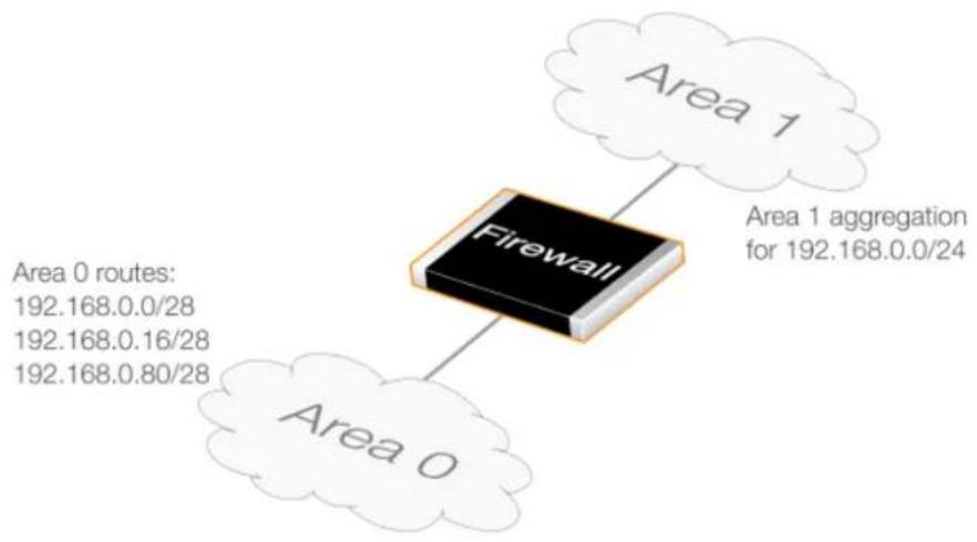
flowchart
graph TD
    A["Firewall"] --> B["Area 0"]
    A --> C["Area 1"]
    A --> D["Area 1 aggregation for 192.168.0.0/24"]
    style A fill:#f9f,stroke:#333
    style B fill:#ccf,stroke:#333
    style C fill:#cfc,stroke:#333
    style D fill:#fcc,stroke:#333
Figure 4.18. OSPF Route Aggregation Example
Here, the three routes on Area 0 can be collapsed into one by setting up an OSPF Aggregate object for the network 192.168.0.0/24 on Area 1.
4.7.3.6. OSPF VLinks
All areas in an OSPF AS must be physically connected to the backbone area (the area with ID 0).
In some cases this is not possible and in that case a Virtual Link (VLink) can be used to connect to the backbone through a non-backbone area.
NetDefendOS OSPF VLink objects are created within an OSPF Area and each object has the following parameters:
General Parameters
Name
Symbolic name of the virtual link.
Neighbor Router ID
The Router ID of the router on the other side of the virtual link.
Authentication
Use Default For AS
Use the values configured in the AS properties page.

Note: Linking partitioned backbones
If the backbone area is partitioned, a virtual link is used to connect the different parts.
In most, simple OSPF scenarios, OSPF VLink objects will not be needed.
4.7.4. Dynamic Routing Rules
This section examines Dynamic Routing Rules. These rules determine which routes can be exported to an OSPF AS from the local routing tables and which can be imported into the local routing tables from the AS.
4.7.4.1. Overview
The Final OSPF Setup Step is Creating Dynamic Routing Rules
After the OSPF structure is created, the final step is always to create a Dynamic Routing Rule on each firewall which allows the routing information that the OSPF AS delivers from remote firewalls to be added to the local routing tables.
Dynamic routing rules are discussed here in the context of OSPF, but can also be used in other contexts.
The Reasons for Dynamic Routing Rules
In a dynamic routing environment, it is important for routers to be able to regulate to what extent they will participate in the routing exchange. It is not feasible to accept or trust all received routing information, and it might be crucial to avoid parts of the routing database getting published to other routers.
For this reason, Dynamic Routing Rules are used to regulate the flow of routing information.
These rules filter either statically configured or OSPF learned routes according to parameters like the origin of the routes, destination, metric and so on. The matched routes can be controlled by actions to be either exported to OSPF processes or to be added to one or more routing tables.
Usage with OSPF
Dynamic Routing Rules are used with OSPF to achieve the following:
- Allowing the import of routes from the OSPF AS into local routing tables.
- Allowing the export of routes from a local routing tables to the OSPF AS.
- Allowing the export of routes from one OSPF AS to another OSPF AS.

Note
The last usage of joining asynchronous systems together is rarely encountered except in very large networks.
OSPF Requires at Least an Import Rule
By default, NetDefendOS will not import or export any routes. For OSPF to function, it is therefore mandatory to define at least one dynamic routing rule which will be an Import rule.
This Import rule specifies the local OSPF Router Process object. This enables the external routes made available in the OSPF AS to be imported into the local routing tables.
Specifying a Filter
Dynamic routing rules allow a filter to be specified which narrows the routes that are imported based on the network reached. In most cases, the Or is within option should be specified as all-nets so that no filter is applied.
When to Use Export Rules
Although an Import rule is needed to import routes from the OSPF AS, the opposite is not true. The export of routes to networks that are part of OSPF Interface objects are automatic.
A dynamic routing export rule must be created to explicitly export the route to the OSPF AS.
Dynamic Routing Rule Objects
The diagram below shows the relationship between the NetDefendOS dynamic routing rule objects.
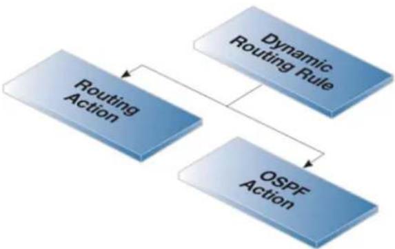
flowchart
graph TD
    A["Routing Action"] --> B["Dynamic Routing Rule"]
    A --> C["OSPF Action"]
Figure 4.19. Dynamic Routing Rule Objects
4.7.4.2. Dynamic Routing Rule
This object defines a dynamic routing rule.
General Parameters
| Name | Specifies a symbolic name for the rule. |
| From OSPF AS | Specifies the from which OSPF AS (in other words, an OSPF Router Process) the route should be imported from into either a routing table or another AS. |
| From Routing Table | Specifies from which routing table a route should be imported into the OSPF AS or copied into another routing table. |
| Destination Interface | Specifies if the rule has to have a match to a certain destination interface. |
Destination Network
| Exactly Matches | Specifies if the network needs to exactly match a specific network. |
| Or is within | Specifies if the network needs to be within a specific network. |
More Parameters
| Next Hop | Specifies what the next hop (in other words, router) needs to be for this rule to be triggered. |
| Metric Specifies an interval that the metric of the routers needs to be in between. | |
| Router ID | Specifies if the rule should filter on Router ID. |
| OSPF Route Type | Specifies if the rule should filter on the OSPF Router Type. |
| OSPF Tag | Specifies an interval that the tag of the routers needs to be in between. |
4.7.4.3. OSPF Action
This object defines an OSPF action.
General Parameters
| Export to Process | Specifies into which OSPF AS the route change should be imported. |
| Forward | If needed, specifies the IP to route via. |
| Tag | Specifies a tag for this route. This tag can be used in other routers forfiltering. |
| Route Type | Specifies what the kind of external route type. Specify 1 if OSPF should regard external routes as type 1 OSPF routes. Type 2 is the most significant cost of a route. |
| OffsetMetric | Increases the metric of an imported route by this value. |
| Limit Metric To | Limits the metrics for these routes to a minimum and maximum value. If a route has a higher or lower value than specified then it will be set to the specified value. |
4.7.4.4. Routing Action
A Routing Action is used to manipulate and export routing changes to one or more local routing tables.
Destination Specifies into which routing table the route changes to the OSPF AS should be imported.
Offset Metric Increases the metric by this value.
Offset Metric Type 2 Increases the Type 2 router's metric by this value.
Limit Metric To Limits the metrics for these routes to a minimum and maximum value. If a route has a higher value than specified then it will be set to the specified value.
Static Route Override Allows the override of the static routes.
Default Route Override Allows the override of the default route.
4.7.5. Setting Up OSPF
Setting up OSPF can seem complicated because of the large number of configuration possibilities that OSPF offers. However, in many cases a simple OSPF solution using a minimum of NetDefendOS objects is needed and setup can be straightforward.
Let us examine again the simple scenario described earlier with just two D-Link firewalls.
In this example we connect together the two firewalls with OSPF so they can share the routes in their routing tables. Both will be inside a single OSPF area which will be part of a single OSPF autonomous system (AS). If unfamiliar with these OSPF concepts, please refer to earlier sections for further explanation.
Beginning with just one of these firewalls, the NetDefendOS setup steps are as follows:
1. Create an OSPF Router object
Create a NetDefendOS OSPF Router Process object. This will represent an OSPF Autonomous Area (AS) which is the highest level in the OSPF hierarchy. Give the object an appropriate name. The Router ID can be left blank since this will be assigned automatically by NetDefendOS.
2. Add an OSPF Area to the OSPF Router
Within the OSPF Router Process created in the previous step, add a new OSPF Area object. Assign an appropriate name and use the value 0.0.0.0 for the Area ID.
An AS can have multiple areas but in many cases only one is needed. The ID 0.0.0.0 identifies this
area as the backbone area which forms the central portion of the AS.
3. Add OSPF Interfaces to the OSPF Area
Within the OSPF Area created in the previous step, add a new OSPF Interface for each physical interface that will be part of the area.
The OSPF Interface object needs the following parameters specified in its properties:
- Interface - the physical interface which will be part of the OSPF area.
• Network - the network on the interface that will be part of the area.
This does not need to be specified and if it is not, the network assigned to the physical interface is used. For example if lan is the interface then lannet will be the default network.
- Interface Type - this would normally be Auto so that the correct type is automatically selected.
- The Passive option No OSPF routers connected to this interface must be enabled if the physical interface does not connect directly to another OSPF Router (in other words, with another D-Link firewall that acts as an OSPF router). For example, the interface may only be connected to a network of clients, in which case the option would be enabled.
The option must be disabled if the physical interface is connected to another firewall which is set up as an OSPF Router. In this example, the physical interface connected to the other firewall would have this option disabled.
4. Add a Dynamic Routing Rule
Finally, a Dynamic Routing Rule needs to be defined to deploy the OSPF network. This involves two steps:
i. A Dynamic Routing Policy Rule object is added. This rule should be an Import rule that enables the option From OSPF Process so that the previously defined OSPF Router Process object is selected. What we are doing is saying that we want to import all routes from the OSPF AS.
In addition, the optional Or is within filter parameter for the destination network must be set to be all-nets. We could use a narrower filter for the destination network but in this case we want all networks.
ii. Within the Dynamic Routing Policy Rule just added, we now add a Routing Action object. Here we add the routing table into the Selected list which will receive the routing information from OSPF.
In the typical case this will be the routing table called main.
There is no need to have a Dynamic Routing Policy Rule which exports the local routing table into the AS since this is done automatically for OSPF Interface objects.
The exception to this is if a route involves an ISP gateway (in other words, a router hop). In this case the route MUST be explicitly exported. The most frequent case when this is necessary is for the all-nets route to the external Internet where the gateway is the ISP's router. Doing this is discussed in the next step.
5. Add a Dynamic Routing Rule for all-nets
Optionally, a Dynamic Routing Rule needs to be defined if any routes except the OSPF Interface routes are to be exported. This involves the following steps
i. A Dynamic Routing Policy Rule object is added. This rule should be an Export rule that enables the option From Routing Table with the main routing table moved to the Selected list.
In addition, the optional Or is within filter parameter for the destination network must be set to be all-nets. This means all routes will be exported.
ii. Within the Dynamic Routing Policy Rule just added, we now add an OSPF Action object. Here set the Export to process option to be the OSPF Router Process which represents the OSPF AS.
6. Repeat these steps on the other firewall
Now repeat steps 1 to 5 for the other firewall that will be part of the OSPF AS and area. The OSPF Router and OSPF Area objects will be identical on each. The OSPF Interface objects will be different depending on which interfaces and networks will be included in the OSPF system.
If more than two firewalls will be part of the same OSPF area then all of them should be configured similarly.
OSPF Routing Information Exchange Begins Automatically
As the new configurations are created in the above steps and then deployed, OSPF will automatically start and begin exchanging routing information. Since OSPF is a dynamic and distributed system, it does not matter in which order the configurations of the individual firewalls are deployed.
When the physical link is plugged in between two interfaces on two different firewalls and those interfaces are configured with OSPF Router Process objects, OSPF will begin exchanging routing information.
Confirming OSPF Deployment
It is now possible to check that OSPF is operating and that routing information is exchanged.
This can be done by examining the routing tables. Routes that have been imported into the routing tables though OSPF are indicated with the letter "O" to the left of the route description. For example, the routes command might give the following output:
| gw-world:/> routes | |||||
| Flags | Network | Iface | Gateway | Local IP | Metric |
| 192.168.1.0/24 | lan | 0 | |||
| 172.16.0.0/16 | wan | 0 | |||
| O | 192.168.2.0/24 | wan 172.16.2.1 | 1 | ||
Here, the route for 192.168.2.0/24 has been imported via OSPF and that network can be found on the WAN interface with the gateway of 172.16.2.1. The gateway in this case is of course the firewall to which the traffic should be sent. That firewall may or may not be attached to the destination network but OSPF has determined that that is the optimum route to reach it.
The CLI command ospf can also be used to indicate OSPF status. The options for this command are fully described in the CLI Reference Guide.
Sending OSPF Traffic Through a VPN Tunnel
In some cases, the link between two D-Link firewalls which are configured with OSPF Router Process objects may be insecure. For example, over the Internet.
In this case, we can secure the link by setting up a VPN tunnel between the two firewalls and telling OSPF to use this tunnel for exchange of OSPF information. Next, we will look at how to set this up and assume that IPsec will be the chosen method for implementing the tunnel.
To create this setup we need to perform the normal OSPF steps described above but with the following additional steps:
1. Set up an IPsec tunnel
First set up an IPsec tunnel in the normal way between the two firewalls A and B. The IPsec setup options are explained in Section 10.2, "VPN Quick Start".
This IPsec tunnel is now treated like any other interface when configuring OSPF in NetDefendOS.
2. Choose a random internal IP network
For each firewall, we need to choose a random IP network using internal, private IPv4 addresses. For example, for firewall A we could use the network 192.168.55.0/24.
This network is used just as a convenience with OSPF setup and will never be associated with a real physical network.
3. Define an OSPF Interface for the tunnel
Define an NetDefendOS OSPF Interface object which has the IPsec tunnel for the Interface parameter. Specify the Type parameter to be point-to-point and the Network parameter to be the network chosen in the previous step, 192.168.55.0/24.
This OSPF Interface tells NetDefendOS that any OPSF related connections to addresses within the network 192.168.55.0/24 should be routed into the IPsec tunnel.
4. Define an OSPF Neighbor
Next, we must explicitly tell OSPF how to find the neighboring OSPF router. Do this by defining a NetDefendOS OSPF Neighbor object. This consists of a pairing of the IPsec tunnel (which is treated like an interface) and the IP address of the router at the other end of the tunnel.
For the IPv4 address of the router, we simply use any single IP address from the network 192.168.55.0/24. For example, 192.168.55.1.
When NetDefendOS sets up OSPF, it will look at this OSPF Neighbor object and will try to send OSPF messages to the IPv4 address 192.168.55.1. The OSPF Interface object defined in the previous step tells NetDefendOS that OSPF related traffic to this IP address should be routed into the IPsec tunnel.
5. Set the Local IP of the tunnel endpoint
To finish the setup for firewall A there needs to be two changes made to the IPsec tunnel setup on firewall B. These are:
i. In the IPsec tunnel properties, the Local Network for the tunnel needs to be set to all-nets. This setting acts as a filter for what traffic is allowed into the tunnel and all-nets will allow all traffic into the tunnel.
ii. In the routing section of the IPsec properties, the Specify address manually option needs to be enabled and the IPv4 address in this example of 192.168.55.1 needs to be entered (in the CLI, OriginatorType is set to manual and the OriginatorIP is 192.168.55.1). This sets the tunnel endpoint IP to be 192.168.55.1 so that all OSPF traffic will be sent to firewall A with this source IP.
The result of doing this is to "core route" OSPF traffic coming from firewall A. In other words, the
traffic is destined for NetDefendOS.
6. Repeat the steps for the other firewall
What we have done so far is allow OSPF traffic to flow from A to B. The steps above need to be repeated as a mirror image for firewall B using the same IPsec tunnel. The same random internal IP network for OSPF setup should be used on both A and B.

Tip: Non-OSPF traffic can also use the tunnel
A VPN tunnel can carry both OSPF traffic as well as other types of traffic. There is no requirement to dedicate a tunnel to OSPF traffic.
4.7.6. An OSPF Example
This section goes through the detailed setup steps for the simple OSPF scenario illustrated below.
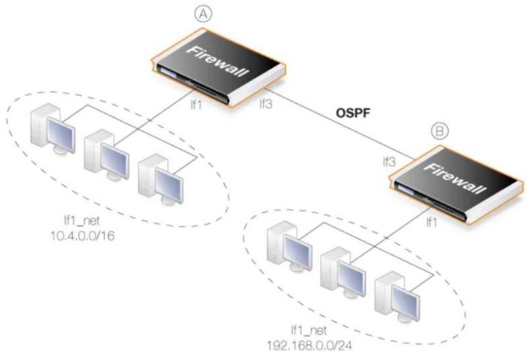
flowchart
graph TD
    A["Firewall"] -->|If1| B["Central Network"]
    A -->|If3| C["Firewall"]
    C -->|If3| B
    B -->|If1| D["Network"]
    style A fill:#f9f,stroke:#333
    style C fill:#f9f,stroke:#333
    style D fill:#ccf,stroke:#333
Figure 4.20. An OSPF Example
Here, two identical D-Link firewalls called A and B are joined together directly via their If3 interfaces. Each has a network of hosts attached to its If1 interface. On one side, If1_net is the IPv4 network 10.4.0.0/16 and on the other side it is the IPv4 network 192.168.0.0/24.
The goal is to configure OSPF on both firewalls so routing information is automatically exchanged and traffic can be correctly routed between the 10.4.0.0/16 network and the 192.168.0.0/24 network. The IP rule set entries that are needed to allow such traffic to flow are not included in this example.
Example 4.10. Creating an OSPF Router Process
First the Autonomous System (AS) must be defined on both firewalls.
On firewall A, create an OSPF Router Process object. Assume the object name will be as_0.
Command-Line Interface
gw-world:/> add OSPFProcess as_0
Web Interface
- Go to: Network > Routing > OSPF > Add > OSPF Router Process
- Enter the process name, in this case as_0
- Click OK
Now, repeat this for firewall B, using the same OSPF Router Process object name of as_0.
Example 4.11. Add an OSPF Area
Now add an OSPF Area object to the OSPF Router Process object as_0 on firewall A. This area will be the OSPF backbone area and will therefore have the ID 0.0.0.0. Assume the name for the area object will be area_0.
Command-Line Interface
First, change the CLI context to be the OSPFProcess object created above:
gw-world:/> cc OSPFProcess as_0
Now, add the area:
gw-world:/as_0> add OSPFArea area_0 AreaID=0.0.0.0
This new OSPFArea object can be displayed with the command:
gw-world:/as_0> show
OSPFArea/
Name Area ID Comments
! area_1 0.0.0.0 <empty>
Web Interface
- Go to: Network > Routing > OSPF
- Select the routing process as_0
- Select Add > OSPF Area
- For the area properties:
- Enter the area name, in this case area_0
• Specify the Area ID as 0.0.0.0
5. Click OK
Now, repeat this for firewall B, using the same OSPF Area object name of area_0.
Example 4.12. Add OSPF Interface Objects
For firewall A, add OSPF Interface objects for each physical interface that is to be part of the OSPF area called area_0.
Command-Line Interface
Assume the context is still the OSPFProcess called as_0 from the last example. Now, change the context to be the OSPFArea that was created previously:
gw-world:/as_0> cc area_0
Next, add the OSPFInterface object:
gw-world:/as_0/area_0> add OSPFInterface If1 Passive=Yes
Enabling the Passive option means that this interface is not connected to another OSPF router. Finally, return to the default CLI context:
gw-world:/as_0/area_0> cc
gw-world:/>
Web Interface
- Go to: Network > Routing > OSPF > as_0 > area_0 > OSPF Interfaces
- Select Add > OSPF Interface
- Select the Interface. In this case, If1
- Select the Advanced tab
- Select No OSPF routers connected to this interface
- Click OK
Just selecting the Interface means that the Network defaults to the network bound to that interface. In this case If1_net.
This should be repeated for all interfaces that will be part of the OSPF area. In this case, the interface If3 must also be added as an OSPFInterface but the Passive property should be left at its default value of enabled since this interface is connected to another router.
firewall B, should then be set up in the same way.
Example 4.13. Import Routes from an OSPF AS into the Main Routing Table
In this example, the routes received using OSPF will be added into the main routing table. To do this, a Dynamic Routing Policy Rule first needs to be created. In this example, the rule is called ImportOSPFRoutes.
The rule must specify from what OSPF AS the routes should be imported. In this example, the OSPF AS configured above, with the name as_0, is used.
Depending on the routing topology, it may be preferable to just import certain routes using the Destination Interface/Destination Network filters, but in this scenario all routes that are within the all-nets network object are allowed.
The steps are first performed for firewall A.
Command-Line Interface
gw-world:/> add DynamicRoutingRule
    OSPFProcess=as_0
    Name=ImportOSPFRoutes
    DestinationNetworkIn=all-nets
Web Interface
- Go to: Network > Routing > Routing Rules > Add > Dynamic Routing Policy Rule
- Specify a suitable name for the rule. For example, ImportOSPFRoutes.
- Select the option From OSPF Process
- Move as_0 from Available to Selected
- Choose all-nets in the ...Or is within filter option for Destination Interface
- Click OK
Now, create a Dynamic Routing Action that will import routes into the routing table. The destination routing table that the routes should be added to is main.
Command-Line Interface
First, change the CLI context to be the DynamicRoutingRule just added for import:
gw-world:/> cc DynamicRoutingRule ImportOSPFRoutes
Next, add a DynamicRoutingRuleAddRoute object:
gw-world:/1(ImportOSPFROutes)> add DynamicRoutingRuleAddRoute Destination=main
Web Interface
- Go to: Network > Routing > Routing Rules
- Click on the newly created ImportOSPFROutes
- Go to: Routing Action > Add > DynamicRoutingRuleAddRoute
- Move the routing table main from Available to Selected
5. Click OK
The same procedure should be repeated for firewall B.
Example 4.14. Exporting the Routes into an OSPF AS
In this example, routes from the main routing table will be exported into an OSPF AS named as_0. This must be done explicitly because routes are not exported automatically.
The exception to this are the routes for the OSPF interface networks which are exported automatically (in this example If1_net and If3_net).
The steps are first performed for firewall A.
First, add a new Dynamic Routing Policy Rule.
Command-Line Interface
gw-world:/> add DynamicRoutingRule
    OSPFProcess=as_0
    Name=ExportDefRoute
    DestinationNetworkIn=all-nets
    DestinationInterface=If3
    From=RTable
    RoutingTable=main
Web Interface
- Go to: Network > Routing > Routing Rules > Add > Dynamic Routing Policy Rule
- Specify a name for the rule. In this case, ExportAllNets
- Select the option From Routing Table
- Move the routing table main to the Selected list
- Choose all-nets in the ...Or is within filter for Destination Interface
- Click OK
Next, create an OSPF Action that will export the filtered route to the specified OSPF AS:
Command-Line Interface
First, change the CLI context to be the DynamicRoutingRule just added for export:
gw-world:/> cc DynamicRoutingRule ExportDefRoute
Next, add a DynamicRoutingRuleExportOSPF object:
gw-world:/2(ExportDefRoute)> add DynamicRoutingRuleExportOSPF
ExportToProcess=as_0
Web Interface
- Go to: Network > Routing > Routing Rules
- Click on the newly created ExportAllNets
- Go to: OSPF Actions > Add > DynamicRoutingRuleExportOSPF
- For Export to process choose as_0
- Click OK
The same procedure should be repeated for firewall B.
4.7.7. OSPF Troubleshooting
There are two special ways of troubleshooting OSPF issues:
• Additional OSPF Log Event Messages.
• The OSPF CLI command.
These are discussed next.
Additional OSPF Log Event Messages
By default, a range of basic log event messages are generated by OSPF operation within NetDefendOS. For example, if the OSPFProcess object running under NetDefendOS is called my_ospf_proc, normal log generation would be enabled with the CLI command:
gw-world:/> set OSPFProcess my_ospf_proc LogEnabled=Yes
This is the default setting so the command is only for illustration.
The following properties can be enabled to provide additional OSPF log messages for troubleshooting and/or monitoring purposes:
- DebugPacket - Log general packet parsing events.
- DebugHello - Log Hello packets.
- DebugDDesc - Log database description packets.
- DebugExchange - Log exchange packets.
- DebugLSA - Log LSA events.
- DebugSPF - Log SPF calculation events.
- DebugRoute - Log routing table manipulation events.
Each of these properties can be assigned one of the following values:
• Off - Nothing is logged.
- Low - Logs all actions.
• Medium - Logs all actions but with more detail.
• High - Logs everything with maximum detail.

Note: The high setting generates large amounts of data
When using the High setting, the firewall will log a large amount of information, even when just connected to a small AS. Changing the advanced setting Log Send Per Sec Limit may be required.
Example 4.15. Enabling OSPF Debug Log Events
In this example, the DebugHello and DebugRoute log events will be enabled for the OSPFProcess called my_ospf_proc.
Command-Line Interface
gw-world:/> set OSPFProcess my_ospf_proc DebugHello=Low DebugRoute=High
Web Interface
- Go to: Network >Routing >OSPF >my_ospf_proc
- Select the Debug option
-
Now enter:
-
Hello Packets: Low
• Routing Table Manipulation: High -
Click OK
The ospf CLI command
The CLI command ospf provides various options for examining the behavior of OSPF in real-time on a particular.
In order to see general OSPF activity on a CLI console, the -snoop option can be used:
gw-world:/> ospf -snoop=on
Usually, there is only one OSPFProcess defined for a firewall and there is therefore no need to specify this explicitly in the command. The snooping processes is turned off with:
gw-world:/> ospf -snoop=off
A snapshot of the state of any of the different OSPF components can be displayed. For example, if an OSPFInterface object has the name ospf_If1, details about this can be shown with the command:
gw-world:/> ospf -iface ospf_If1
A similar snapshot can be displayed for areas, neighbors, routes and LSAs.
OSPF interface operation can also be selectively halted and restarted. For example, to stop the OSPFInterface called ospf_If1, the CLI command would be:
gw-world:/> ospf -ifacedown ospf_If1
To restart the same interface:
gw-world:/> ospf -ifaceup ospf_If1
An entire functioning OSPFRouteProcess can also be halted. For example, assuming that there is only one OSPFRouteProcess object defined in the configuration, the CLI command to halt it is:
gw-world:/> ospf -execute=stop
To start the stopped OSPFRouteProcess:
gw-world:/> ospf -execute=start
To stop and then start in a single command:
gw-world:/> ospf -execute=restart
The ospf command options are fully described in the separate NetDefendOS CLI Reference Guide.
4.8. Multicast Routing
4.8.1. Overview
The Multicast Problem
Certain types of Internet interactions, such as conferencing and video broadcasts, require a single client or host to send the same packet to multiple receivers. This could be achieved through the sender duplicating the packet with different receiving IP addresses or by a broadcast of the packet across the Internet. These solutions waste large amounts of sender resources or network bandwidth and are therefore not satisfactory. An appropriate solution should also be able to scale to large numbers of receivers.
The Multicast Routing Solution
Multicast Routing solves the problem by the network routers themselves, replicating and forwarding packets via the optimum route to all members of a group.
The IETF standards that allow multicast routing are the following:
- Class D of the IPv4 address space which is reserved for multicast traffic. Each multicast IP address represent an arbitrary group of recipients.
- The Internet Group Membership Protocol (IGMP) allows a receiver to tell the network that it is a member of a particular multicast group.
- Protocol Independent Multicast (PIM) is a group of routing protocols for deciding the optimal path for multicast packets.
Underlying Principles
Multicast routing functions on the principle that an interested receiver joins a group for a multicast by using the IGMP protocol. PIM routers can then duplicate and forward packets to all members of such a multicast group, thus creating a distribution tree for packet flow. Rather than acquiring new network information, PIM uses the routing information from existing protocols, such as OSPF, to decide the optimal path.
Reverse Path Forwarding
A key mechanism in the multicast routing process is Reverse Path Forwarding. For unicast traffic, a router is concerned only with a packet's destination. With multicast, the router is also concerned with a packets source since it forwards the packet on paths which are known to be downstream, away from the packet's source. This approach is adopted to avoid loops in the distribution tree.
Routing to the Correct Interface
By default, multicast packets are routed by NetDefendOS to the core interface (in other words, to NetDefendOS itself). Multicast Policy objects are created in the IP rule set in order to perform forwarding to the correct interfaces. This is demonstrated in the Example 4.16, "Multicast Forwarding With No Address Translation".
Promiscuous Mode
If an IP rule set entry exists which applies to a multicast packet's destination IP address, then that Ethernet interface automatically gets its receive mode set to promiscuous in order to receive multicast packets. Promiscuous mode means that traffic with a destination MAC address that does not match the Ethernet interface's MAC address will be sent to NetDefendOS and not discarded by the interface. Promiscuous mode is enabled automatically by NetDefendOS and the administrator does not need to worry about doing this.
With multicast only, the usage of promiscuous mode can be explicitly controlled using the Ethernet object property Receive Multicast Traffic which has a default value of Auto. If this property is set to Off, the multicast forwarding feature cannot function.
If the administrator enters a CLI ifstat
4.8.2. Multicast Forwarding with Multicast Policies
The Multicast Policy is used to achieve duplication and forwarding of packets through more than one interface. This feature implements multicast forwarding in NetDefendOS, where a multicast packet is sent through several interfaces.
Note that since this rule overrides the normal routing tables, packets that should be duplicated by the Multicast Policy need to be routed to the core interface.
By default, the multicast IP range 224.0.0.0/4 is always routed to core and does not have to be manually added to the routing tables. Each specified output interface can individually be configured with static address translation of the destination address. The Interface field in the Interface/Net Tuple dialog may be left empty if the IPAddress field is set. In this case, the output interface will be determined by a route lookup on the specified IP address.
The Multicast Policy can operate in one of two modes:
- Using IGMP
The traffic flow specified by the Multicast Policy must have been requested by hosts using IGMP before any multicast packets are forwarded through the specified interfaces. This is the default behavior of NetDefendOS.
- Not using IGMP
The traffic flow will be forwarded according to the specified interfaces directly without any inference from IGMP.
Example 4.16. Multicast Forwarding With No Address Translation
This example shows how to configure multicast forwarding together with IGMP. The multicast sender is 192.168.10.1 and generates the multicast streams 239.192.10.0/24:1234. These multicast streams should be forwarded from interface wan through the interfaces if1, if2 and if3. The streams should only be forwarded if some host has requested the streams using the IGMP protocol.
A Multicast Policy object will be created to forward the multicast groups. All groups have the same sender that has the IP address 192.168.10.1, which is located behind the wan interface.
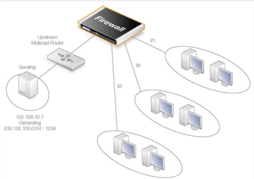
flowchart
graph TD
    A["Firewall"] -->|if1| B["Computer 1"]
    A -->|if2| C["Computer 2"]
    A -->|if3| D["Computer 3"]
    A -->|if4| E["Computer 4"]
    F["Upstream Multicast Router"] --> G["Sending"]
    G --> H["192.168.10.1 Generating 239.192.100.0/24: 1234"]
The multicast groups should only be forwarded to the outgoing interfaces if clients behind those interfaces have requested the groups using IGMP. The following steps will configure forwarding of the multicast traffic.
IGMP is configured separately and this is described in Section 4.8.3.2, "IGMP Rules Configuration with Address Translation". It is configured in the same way that it is configured when using other IP rule set entries.
Web Interface
A. Create a custom Service object for multicast:
-
Go to: Objects > Services > Add > TCP/UDP
-
Now enter:
-
Name: my_multicast_service
- Type: UDP
- Destination: 1234
B. Create a Multicast Policy object:
-
Go to: Policies > Firewalling > Main IP Rules > Add > Multicast Policy
-
Now enter:
• Name: my_multicast_policy
- Source Interface: wan
• Source Network: 192.168.10.1
- Destination Interface: core
• Destination Network: 239.192.10.0/24
• Service: my_multicast_service
-
Under Destination Translation add one entry each for the output interfaces if1, if2 and if3 and leave the IP Address fields blank since no destination address translation is required.
-
Enable the option Require IGMP
-
Click OK
IGMP configuration for this example is described in Section 4.8.3.1, "IGMP Rules Configuration with No Address Translation".
Creating a Multicast Policy with the CLI
Creating multicast policies through the CLI requires some additional explanation.
The CLI command to create a Multicast Policy is the following:
gw-world:/> add MulticastPolicy Name=mc_policy1
SourceNetwork=<srcnet>
SourceInterface=<srcif>
DestinationInterface=<srcif>
DestinationNetwork=<destnet>
Service=<service>
MultiplexArgument={outif1;ip1},{outif2;ip2},{outif3;ip3}...
The two values {outif;ip} represent a combination of output interface and, if address translation of a group is needed, an IP address.
If, for example, multiplexing of the multicast group 239.192.100.50 is required to the output interfaces if2 and if3, then the command to create the rule would be:
gw-world:/> add MulticastPolicy Name=mc_policy2
SourceNetwork=<srcnet>
SourceInterface=<if1>
DestinationInterface=core
DestinationNetwork=239.192.100.50
Service=<service>
MultiplexArgument={if2;},{if3;}
The destination interface is core since 239.192.100.50 is a multicast group. No address translation of 239.192.100.50 was added but if it is required for, say, if2 then the final argument would be:
MultiplexArgument={if2;<new_ip_address>},{if3;}
Example 4.17. Multicast Forwarding With Address Translation
This example is based on the previous one but this time the multicast group is translated. When the multicast streams 239.192.10.0/24 are forwarded through the if2 interface, the multicast groups should be translated into 237.192.10.0/24. No address translation should be made when
forwarding through interface if1. This is illustrated in the diagram below.
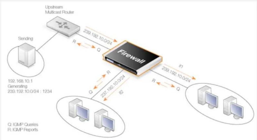
flowchart
graph TD
    A["Upstream Multicast Router"] -->|239.192.10.0/24| B["Firewall"]
    C["Sending"] -->|192.168.10.1 Generating 239.192.10.0/24 : 1234| B
    B -->|237.192.10.0/24 #2| D["IGMPP Queries"]
    B -->|239.192.10.0/24 if1| E["IGMPP Reports"]
    B -->|R Q| F["Computer"]
    B -->|R Q| G["Computer"]
Web Interface
A. Create a custom service for multicast called multicast_service:
- Go to: Objects > Services > Add > TCP/UDP
-
Now enter:
-
Name: multicast_service
- Type: UDP
- Destination: 1234
B. Create a Multicast Policy:
- Go to: Policies > Firewalling > Main IP Rules > Add > Multicast Policy
-
Now enter:
-
Name: my_multicast_sat
- Source Interface: wan
• Source Network: 192.168.10.1 -
Destination Interface: core
• Destination Network: 239.192.10.0/24
• Service: multicast_service -
Under Destination Translation add interface if1 and leave the IP Address field blank since no destination address translation is required. Add interface if2 but this time, enter 237.192.10.0 as the IPAddress.
-
Enable the option Require IGMP
5. Click OK
IGMP configuration for this example is described in Section 4.8.3.2, "IGMP Rules Configuration with Address Translation".
4.8.3. IGMP Configuration
IGMP signaling between hosts and routers can be divided into two categories:
• IGMP Reports
Reports are sent from hosts towards the router when a host wants to subscribe to new multicast groups or change current multicast subscriptions.
- IGMP Queries
Queries are IGMP messages sent from the router towards the hosts in order to make sure that it will not close any stream that some host still wants to receive.
Normally, both types of rule have to be specified for IGMP to function but there are two exceptions:
- If the multicast source is located on a network directly connected to the router, no query rule is needed.
- If a neighboring router is statically configured to deliver a multicast stream to the D-Link firewall, an IGMP query would also not have to be specified.
NetDefendOS supports two IGMP modes of operation:
- Snoop Mode
- Proxy Mode
The operation of these two modes are shown in the following illustrations:
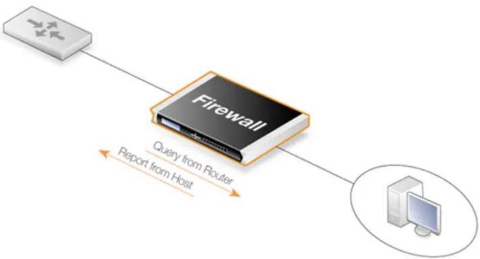
flowchart
graph TD
    A["Router"] --> B["Firewall"]
    B --> C["Host"]
    B -->|Query from Router Report from Host| C
Figure 4.21. Multicast Snoop Mode

flowchart
graph TD
    A["Router"] -->|Query from Router Report from FW| B["Firewall"]
    B -->|Query from FW Report from Host| C["Computer"]
Figure 4.22. Multicast Proxy Mode
In Snoop Mode, the D-Link firewall will act transparently between the hosts and another IGMP router. It will not send any IGMP Queries. It will only forward queries and reports between the other router and the hosts.
In Proxy Mode, the firewall will act as an IGMP router towards the clients and actively send queries. Towards the upstream router, the firewall will be acting as a normal host, subscribing to multicast groups on behalf of its clients.
4.8.3.1. IGMP Rules Configuration with No Address Translation
This example describes the IGMP rules needed for configuring IGMP rules for Example 4.16, "Multicast Forwarding With No Address Translation". No Address Translation scenario described above. The router is required to act as a host towards the upstream router and therefore IGMP must be configured to run in proxy mode.
Example 4.18. IGMP - No Address Translation
The following example requires a configured interface group IfGrpClients including interfaces if1, if2 and if3. The IP address of the upstream IGMP router is known as UpstreamRouterIP.
Two rules are needed. The first one is a report rule that allows the clients behind interfaces if1, if2 and if3 to subscribe for the multicast groups 239.192.10.0/24. The second rule, is a query rule that allows the upstream router to query us for the multicast groups that the clients have requested.
The following steps need to be executed to create the two rules.
Web Interface
A. Create the first IGMP Rule:
-
Go to: Network > Routing > IGMP Rules > Add > IGMP Rule
-
Under General enter:
• Name: A suitable name for the rule, for example Reports
- Type: Report
• Action: Proxy
• Output: wan (this is the relay interface)
-
Under Address Filter enter:
-
Source Interface: IfGrpClients
• Source Network: if1net, if2net, if3net - Destination Interface: core
-
Destination Network: auto
• Multicast Source: 192.168.10.1
• Multicast Destination: 239.192.10.0/24 -
Click OK
B. Create the second IGMP Rule:
-
Again, go to: Network > Routing > IGMP Rules > Add > IGMP Rule
-
Under General enter:
• Name: A suitable name for the rule, for example Queries
- Type: Query
• Action: Proxy
• Output: IfGrpClients (this is the relay interface)
-
Under Address Filter enter:
-
Source Interface: wan
- Source Network: UpstreamRouterIp
- Destination Interface: core
-
Destination Network: auto
• Multicast Source: 192.168.10.1
• Multicast Group: 239.192.10.0/24 -
Click OK
4.8.3.2. IGMP Rules Configuration with Address Translation
The following examples illustrates the IGMP rules needed to configure IGMP according to the Address Translation scenario described above in Example 4.17, "Multicast Forwarding With Address Translation". We need two IGMP report rules, one for each client interface. The interface if1 uses no address translation and if2 translates the multicast group to 237.192.10.0/24. We also need two query rules, one for the translated address and interface, and one for the original address towards if1.
Two examples are provided, one for each pair of report and query rule. The upstream multicast router uses IP UpstreamRouterIP.
Example 4.19. if1 Configuration
The following steps needs to be executed to create the report and query rule pair for if1 which uses no address translation.
Web Interface
A. Create the first IGMP Rule:
-
Go to: Network > Routing > IGMP Rules > Add > IGMP Rule
-
Under General enter:
• Name: A suitable name for the rule, for example Reports_if1
- Type: Report
• Action: Proxy
• Output: wan (this is the relay interface)
-
Under Address Filter enter:
-
Source Interface: if1
- Source Network: if1net
- Destination Interface: core
-
Destination Network: auto
• Multicast Source: 192.168.10.1
• Multicast Group: 239.192.10.0/24 -
Click OK
B. Create the second IGMP Rule:
-
Again, go to: Network > Routing > IGMP Rules > Add > IGMP Rule
-
Under General enter:
-
Name: A suitable name for the rule, for example Queries_if1
- Type: Query
• Action: Proxy
• Output: if1 (this is the relay interface)
-
Under Address Filter enter:
-
Source Interface: wan
- Source Network: UpstreamRouterIp
- Destination Interface: core
-
Destination Network: auto
• Multicast Source: 192.168.10.1
• Multicast Group: 239.192.10.0/24 -
Click OK
Example 4.20. if2 Configuration - Group Translation
The following steps needs to be executed to create the report and query rule pair for if2 which translates the multicast group. Note that the group translated therefore the IGMP reports include the translated IP addresses and the queries will contain the original IP addresses
Web Interface
A. Create the first IGMP Rule:
- Go to: Network > Routing > IGMP Rules > Add > IGMP Rule
- Under General enter:
• Name: A suitable name for the rule, for example Reports_if2
- Type: Report
• Action: Proxy
• Output: wan (this is the relay interface)
-
Under Address Filter enter:
-
Source Interface: if2
- Source Network: if2net
- Destination Interface: core
-
Destination Network: auto
• Multicast Source: 192.168.10.1
• Multicast Group: 239.192.10.0/24 -
Click OK
B. Create the second IGMP Rule:
-
Again, go to: Network > Routing > IGMP Rules > Add > IGMP Rule
-
Under General enter:
-
Name: A suitable name for the rule, for example Queries_if2
-
Type: Query
• Action: Proxy
• Output: if2 (this is the relay interface) -
Under Address Filter enter:
-
Source Interface: wan
- Source Network: UpstreamRouterIp
- Destination Interface: core
-
Destination Network: auto
• Multicast Source: 192.168.10.1
• Multicast Group: 239.192.10.0/24 -
Click OK

Advanced IGMP Settings
There are a number of IGMP advanced settings which are global and apply to all interfaces which do not have IGMP settings explicitly specified for them.
4.8.4. Advanced IGMP Settings
The following advanced settings for IGMP can be found in the Web Interface by going to: Network > Routing > Advanced Multicast Settings
Auto Add Multicast Core Route
This setting will automatically add core routes in all routing tables for the multicast IP address range 224.0.0.0/4. If the setting is disabled, multicast packets might be forwarded according to the default route.
Default: Enabled
IGMP Before Rules
For IGMP traffic, by-pass the normal IP rule set and consult the IGMP rule set.
Default: Enabled
IGMP React To Own Queries
The firewall should always respond with IGMP Membership Reports, even to queries originating from itself. Global setting on interfaces without an overriding IGMP Setting.
Default: Disabled
IGMP Lowest Compatible Version
IGMP messages with a version lower than this will be logged and ignored. Global setting on interfaces without an overriding IGMP Setting.
Default: IGMPv1
IGMP Router Version
The IGMP protocol version that will be globally used on interfaces without a configured IGMP Setting. Multiple querying IGMP routers on the same network must use the same IGMP version. Global setting on interfaces without an overriding IGMP Setting.
Default: IGMPv3
IGMP Last Member Query Interval
The maximum time in milliseconds until a host has to send an answer to a group or group-and-source specific query. Global setting on interfaces without an overriding IGMP Setting.
Default: 5,000
IGMP Max Total Requests
The maximum global number of IGMP messages to process each second.
Default: 1000
IGMP Max Interface Requests
The maximum number of requests per interface and second. Global setting on interfaces without an overriding IGMP Setting.
Default: 100
IGMP Query Interval
The interval in milliseconds between General Queries sent by the device to refresh its IGMP state. Global setting on interfaces without an overriding IGMP Setting.
Default: 125,000
IGMP Query Response Interval
The maximum time in milliseconds until a host has to send a reply to a query. Global setting on
interfaces without an overriding IGMP Setting.
Default: 10,000
IGMP Robustness Variable
IGMP is robust to (IGMP Robustness Variable - 1) packet losses. Global setting on interfaces without an overriding IGMP Setting.
Default: 2
IGMP Startup Query Count
The firewall will send IGMP Startup Query Count general queries with an interval of IGMPStartupQueryInterval at startup. Global setting on interfaces without an overriding IGMP Setting.
Default: 2
IGMP Startup Query Interval
The interval of General Queries in milliseconds used during the startup phase. Global setting on interfaces without an overriding IGMP Setting.
Default: 30,000
IGMP Unsolicited Report Interval
The time in milliseconds between repetitions of an initial membership report. Global setting on interfaces without an overriding IGMP Setting.
Default: 1,000
4.8.5. Tunneling Multicast using GRE
It is possible to tunnel NetDefendOS multicast between two D-Link firewalls through a GRE tunnel. The multicast server will be behind one firewall and the clients behind the other with a GRE tunnel linking the two firewalls.
Setup Issues
There are certain issues that must be noted with tunneling multicast:
- Make sure that the multicast server is sending the stream with a higher TTL than 1 (VLC uses TTL=1 by default).
- When using IGMP, make sure that the destination network is not set to all-nets. If it is, the multiplex rule will not forward the stream to the correct interface.
- Multicast Policy rule set entries must be set up both on the firewall that the server is behind and on the firewall that the clients are behind (in other words, the tunnel terminator).
- Incoming and outgoing IGMP rules for reporting and querying must be configured on both sides of the tunnel if IGMP is used.
Tunneling Setup Summary
The following components are needed on both the client and server side:
- Configure a GRE Tunnel object with the remote network being the client network for the server side and the server network on the client side.
- Configure routes that route multicast traffic bound for the network on the other side through the GRE tunnel.
- Configure a Multicast Policy on both sides.
- For the Multicast Policy objects, enable the option: Multicast traffic must have been requested using IGMP before it is forwarded.
- Configure IGMP rule objects for the multicast traffic.
An Example Configuration
An example multicast tunneling scenario is illustrated below.
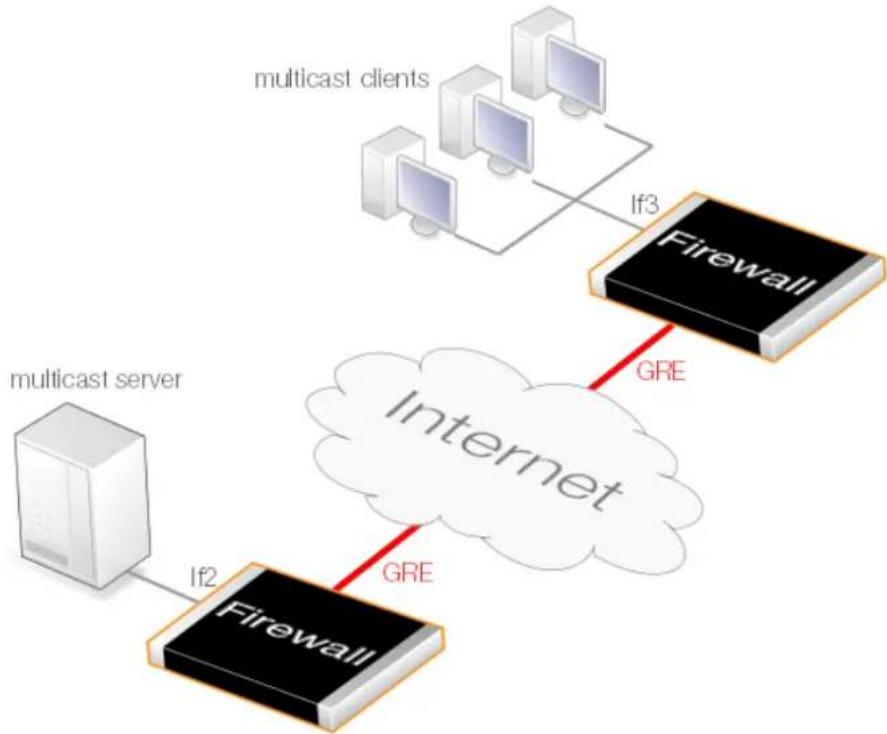
flowchart
graph TD
    A["multicast clients"] -->|If3| B["Firewall"]
    C["multicast server"] -->|If2| D["Firewall"]
    B -->|GRE| E["Internet"]
    D -->|GRE| E
Figure 4.23. Tunneling Multicast using GRE
The IPv4 address book object called mc_group on both sides of the tunnel is the same multicast IPv4 range. In this example, 239.100.100.0/24.
A. Server Side Configuration Setup
For the server side configuration, assume the client network is the IPv4 address book object
client_net, the local internal tunnel endpoint is If2_ip (the server is on the If2 interface). A GRE tunnel called gre_to_clients is configured and the remote network is the address book object called client_net.
GRE Tunnel
| Name IP Address Remote Endpoint Remote Network | ||
| gre_to_clients If2_ip client_interface_ip client_net |
Routes
Provided that the above GRE object has the option to automatically add routes enabled, the following route will be added by NetDefendOS to the main routing table.
| Network Interface | |
| client_net gre_to_clients |
Services
| Name Type Destination Ports | ||
| mc_stream udp | 1234 |
IP Rule Set Entries
| Entry Type | Source Interface | Source Network | Destination Interface | Destination Network | Service | Multiplex Interface |
| Multicast Policy | lf2 | lf2_net | core | mc_group | mc_stream | gre_to_clients |
| IP Policy | lf2 | lf2_net | core | mc_group | mc_stream |
IGMP Rules
| Type | Action | Source Interface | Source Network | Multicast Group | Multicast Source | Relay Interface |
| Query | Proxy | lf2 | lf2_net | mc_group | all-nets | gre_to_clients |
| Report | Proxy | gre_clients | all-nets | all-nets | all-nets | lf2 |
B. Client Side Configuration Setup
For the client side configuration, assume the server network is the IPv4 address book object server_net, the local internal tunnel endpoint is If3_ip (the clients are on the If3 interface). A GRE tunnel called gre_to_server is configured and the remote network is the address book object called server_net.
GRE Tunnel
| Name IP Address Remote Endpoint Remote Network | ||
| gre_to_server | If3_ip server_interface_ip | server_net |
Routes
Provided that the above GRE object has the option to automatically add routes enabled, the following route will be added by NetDefendOS to the main routing table.
| Network Interface | |
| server_net gre_to_server |
Services
| Name Type Destination Ports | ||
| mc_stream udp 1234 |
IP Rule Set Entries
| Entry Type Source | Interface | Source Network | Destination Interface | Destination Network | Service Multiplex | Interface |
| Multicast Policy | gre_to_server server | server_net core mc | group mc_stream | lf3 | ||
| IP Policy gre_to_server server | server server_net | core mc_group | mc_stream |
IGMP Rules
| Type Action Source | Interface | Source Network | Multicast Group | Multicast Source | Relay Interface | |
| Report | Proxy | lf3 | lf3_net | mc_group | all-nets | gre_to_server |
| Query | Proxy | gre_to_server | all-nets | all-nets | all-nets | lf3 |
4.9. Transparent Mode
4.9.1. Overview
Transparent Mode Usage
The NetDefendOS Transparent Mode feature allows a D-Link firewall to be placed at a point in a network without any reconfiguration of the network and without hosts being aware of its presence. All NetDefendOS features can then be used to monitor and manage traffic flowing through that point. NetDefendOS can allow or deny access to different types of services (for example HTTP) and in specified directions. As long as users are accessing the services permitted, they will not be aware of the firewall's presence.
Network security and control can therefore be significantly enhanced with deployment of a D-Link firewall operating in transparent mode but while disturbance to existing users and hosts is minimized.

Note: HA does not support transparent mode
There is no state synchronization for switch routes and therefore transparent mode in a NetDefendOS high availability cluster. Loop avoidance will not function at all. For these reasons, transparent mode should not be configured in an HA cluster.
Switch Routes
Transparent mode is enabled by specifying a Switch Route instead of a standard Route in routing tables. The switch route usually specifies that the network all-nets is found on a specific interface. NetDefendOS then uses ARP message exchanges over the connected Ethernet network to identify and keep track of which host IP addresses are located on that interface (this is explained further below). There should not be a normal non-switch route for that same interface.
In certain, less usual circumstances, switch routes can have a network range specified instead of all-nets. This is usually when a network is split between two interfaces but the administrator does not know exactly which users are on which interface.
Broadcast Packet Forwarding
By default, broadcast packets will not be forwarded with transparent mode. Forwarding must be switched on by enabling the property Forward broadcast packets on switch routes and this must be done for the routes for both the source and destination interface. This is explained further in Section 4.2.7, "Broadcast Packet Forwarding".

Note:IPv6 is not supported in switch routes
Although IPv6 is supported in normal NetDefendOS routes, it is not supported in switch routes. This means that IPv6 cannot be used with transparent mode.
Usage Scenarios
Two examples of transparent mode usage are:
• Implementing Security Between Users
In a corporate environment, there may be a need to protect the computing resources of different departments from one another. The finance department might require access to only a restricted set of services (HTTP for example) on the sales department's servers whilst the sales department might require access to a similarly restricted set of applications on the finance department's hosts. By deploying a single D-Link firewall between the two department's physical networks, transparent but controlled access can be achieved.
- Controlling Internet Access
An organization allows traffic between the external Internet and a range of public IPv4 addresses on an internal network. Transparent mode can control what kind of service is permitted to these IP addresses and in what direction. For instance the only services permitted in such a situation may be HTTP access out to the Internet. This usage is dealt with in greater depth below in Section 4.9.2, "Enabling Internet Access".
Comparison with Routing Mode
The D-Link firewall can be regarded as operating in either of two modes:
- Routing Mode using non-switch routes.
• Transparent Mode using switch routes.
With non-switch routes, the firewall acts as a router and routing operates at layer 3 of the OSI model. If the firewall is placed into a network for the first time, or if network topology changes, the routing configuration must therefore be checked and adjusted to ensure that the routing table is consistent with the new layout. Reconfiguration of IP settings may be required for pre-existing routers and protected servers. This works well when comprehensive control over routing is desired.
With switch routes, the D-Link firewall operates in transparent mode and resembles a OSI Layer 2 Switch in that it screens IP packets and forwards them transparently to the correct interface without modifying any of the source or destination information at the IP or Ethernet levels. This is achieved by NetDefendOS keeping track of the MAC addresses of the connected hosts and NetDefendOS allows physical Ethernet networks on either side of the firewall to act as though they were a single logical IP network. (See Appendix D, The OSI Framework for an overview of the OSI layer model.)
Two benefits of transparent mode over conventional routing are:
- A user can move from one interface to another in a "plug-n-play" fashion, without changing their IP address (assuming their IP address is fixed). The user can still obtain the same services as before (for example HTTP, FTP) without any need to change routes.
• The same network address range can exist on several interfaces.

Note: Transparent and Routing Mode can be combined
Transparent mode and routing mode can operate together on a single D-Link firewall. Switch Routes can be defined alongside standard non-switch routes although the two types cannot be combined for the same interface. An interface operates in one mode or the other.
It is also possible to create a hybrid case by applying address translation on otherwise transparent traffic.
How Transparent Mode Functions
In transparent mode, NetDefendOS allows ARP transactions to pass through the D-Link firewall, and determines from this ARP traffic the relationship between IP addresses, physical addresses and interfaces. NetDefendOS remembers this address information in order to relay IP packets to the correct receiver. During the ARP transactions, neither of the endpoints will be aware of the firewall.
When beginning communication, a host will locate the target host's physical address by broadcasting an ARP request. This request is intercepted by NetDefendOS and it sets up an internal ARP Transaction State entry and broadcasts the ARP request to all the other switch-route interfaces except the interface the ARP request was received on. If NetDefendOS receives an ARP reply from the destination within a configurable timeout period, it will relay the reply back to the sender of the request, using the information previously stored in the ARP Transaction State entry.
During the ARP transaction, NetDefendOS learns the source address information for both ends from the request and reply. NetDefendOS maintains two tables to store this information: the Content Addressable Memory (CAM) and Layer 3 Cache. The CAM table tracks the MAC addresses available on a given interface and the Layer 3 cache maps an IP address to MAC address and interface. As the Layer 3 Cache is only used for IP traffic, Layer 3 Cache entries are stored as single host entries in the routing table.
For each IP packet that passes through the D-Link firewall, a route lookup for the destination is done. If the route of the packet matches a Switch Route or a Layer 3 Cache entry in the routing table, NetDefendOS knows that it should handle this packet in a transparent manner. If a destination interface and MAC address is available in the route, NetDefendOS has the necessary information to forward the packet to the destination. If the route was a Switch Route, no specific information about the destination is available and the firewall will have to discover where the destination is located in the network.
Discovery is done by NetDefendOS sending out ARP as well as ICMP (ping) requests, acting as the initiating sender of the original IP packet for the destination on the interfaces specified in the Switch Route. If an ARP reply is received, NetDefendOS will update the CAM table and Layer 3 Cache and forward the packet to the destination.
If the CAM table or the Layer 3 Cache is full, the tables are partially flushed automatically. Using the discovery mechanism of sending ARP and ICMP requests, NetDefendOS will rediscover destinations that may have been flushed.
Enabling Transparent Mode
To enable NetDefendOS transparent mode, the following steps are required:
-
The interfaces that are to be transparent should be first collected together into a single Interface Group object. Interfaces in the group should be marked as Security transport equivalent if hosts are to move freely between them.
-
A Switch Route is now created in the appropriate routing table and the interface group associated with it. Any existing non-switch routes for interfaces in the group should be removed from the routing table.
For the Network parameter in the switch route, specify all-nets or alternatively, specify a network or range of IP addresses that will be transparent between the interfaces (this latter option is discussed further below).
- Create the appropriate IP rules in the IP rule set to allow the desired traffic to flow between the interfaces operating in transparent mode.
If no restriction at all is to be initially placed on traffic flowing in transparent mode, the
following single IP rule could be added but more restrictive IP rules are recommended.
| Action | Src Interface | Src Network | Dest Interface | Dest Network | Service |
| Allow any all-nets any all-nets all_services | |||||
Restricting the Network Parameter
As NetDefendOS listens to ARP traffic, it continuously adds single host routes to the routing table as it discovers on which interface IP addresses are located. As the name suggests, single host routes give a route for a single IP address. The number of these routes can therefore become large as connections are made to more and more hosts.
A key advantage of specifying a network or a range of IP addresses instead of all-nets for the Network parameter is that the number of routes automatically generated by NetDefendOS will be significantly smaller. A single host route will only be added if the IP address falls within the network or address specified. Reducing the number of routes added will reduce the processing overhead of route lookups.
Specifying a network or address range is, of course, only possible if the administrator has some knowledge of the network topology and often this may not be the case.
Multiple Switch Routes are Connected Together
The setup steps listed above describe placing all the interfaces into a single interface group object which is associated with a single switch route.
An alternative to one switch route is to not use an interface group but instead use an individual switch route for each interface. The end result is the same. All the switch routes defined in a single routing table will be connected together by NetDefendOS and no matter how interfaces are associated with the switch routes, transparency will exist between them.
For example, if the interfaces if1 to if6 appear in a switch routes in routing table A, the resulting interconnections will be as illustrated below.
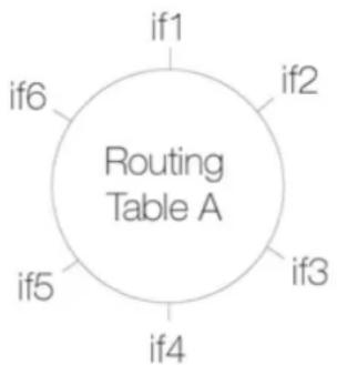
flowchart
graph TD
    A["if1"] --> B["Routing Table A"]
    C["if2"] --> B
    D["if3"] --> B
    E["if4"] --> B
    F["if5"] --> B
    G["if6"] --> B
Connecting together switch routes in this way only applies, however, if all interfaces are associated with the same routing table. The situation where they are not, is described next.
Creating Separate Transparent Mode Networks
If we now have two routing tables A and B so that interfaces if1, if2 and if3 appear in a switch route in table A and interfaces if4, if5, if6 appear in a switch route in table B, the resulting interconnections will be as illustrated below.
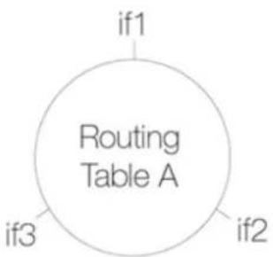
flowchart
graph TD
    A["if1"] --> B["Routing Table A"]
    C["if2"] --> B
    D["if3"] --> B
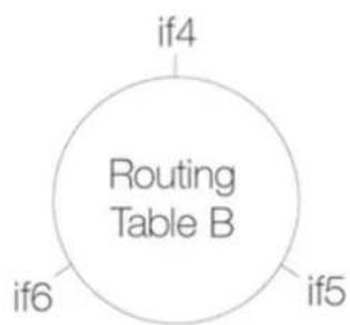
flowchart
graph TD
    A["if4"] --> B["Routing Table B"]
    C["if5"] --> B
    D["if6"] --> B
The diagram above illustrates how switch route interconnections for one routing table are completely separate from the switch route interconnections for another routing table. By using different routing tables in this way we can create two separate transparent mode networks.
The routing table used for an interface is decided by the Routing Table Membership parameter for each interface. To implement separate transparent mode networks, interfaces must have their Routing Table Membership reset.
By default, all interfaces have Routing Table Membership set to be all routing tables. Also by default, one main routing table always exists and once an additional routing table has been defined, the Membership for any interface can then be set to be that new table.
Transparent Mode with VLANs
If transparent mode is being set up for all hosts and users on a VLAN then the technique described above of using multiple routing tables also applies. A dedicated routing table should be defined for each VLAN ID and switch routes should then be defined in that routing table which refer to the VLAN interfaces. The reason for doing this is to restrict the ARP requests to the interfaces on which the VLAN is defined.
To better explain this, let us consider a VLAN vlan5 which is defined on two physical interfaces called if1 and if2. Both physical interfaces have switch routes defined so they operate in transparent mode. Two VLAN interfaces with the same VLAN ID are defined on the two physical interfaces and they are called vlan5_if1 and vlan5_if2.
For the VLAN to operate in transparent mode we create a routing table with the ordering set to only and which contains the following 2 switch routes:
| Network Interface | |
| all-nets vlan5_if1 | |
| all-nets vlan5_if2 |
Instead of creating individual entries, an interface group could be used in the above routing table.
No other non-switched routes should be in this routing table because traffic that follows such routes will be tagged incorrectly with the VLAN ID.
Finally, we must associate this routing table with its VLAN interface by defining a Policy Based Routing Rule.
Enabling Transparent Mode Directly on Interfaces
The recommended way to enable transparent mode is to add switch routes, as described above. An alternative method is to enable transparent mode directly on an interface (a check box for this is provided in the graphical user interfaces). When enabled in this way, default switch routes are automatically added to the routing table for the interface and any corresponding non-switch
routes are automatically removed. This method is used in the detailed examples given later.
High Availability and Transparent Mode
Switch Routes cannot be used with High Availability and therefore true transparent mode cannot be implemented with a NetDefendOS High Availability Cluster.
Instead of Switch Routes the solution in a High Availability setup is to use Proxy ARP to separate two networks. This is described further in Section 4.2.6, "Proxy ARP". The key disadvantage with this approach is that firstly, clients will not be able to roam between NetDefendOS interfaces, retaining the same IP address. Secondly, and more importantly, their network routes will need to be manually configured for proxy ARP.
Transparent Mode with DHCP
In most transparent mode scenarios, the IP address of clients is predefined and fixed and is not dynamically fetched using DHCP. It is a key advantage of using transparent mode that users can plug in anywhere and NetDefendOS can route traffic correctly after determining their location and IP address from ARP exchanges.
However in some transparent mode scenarios, user IP addresses might be allocated by a DHCP server. For example, it may be an ISP's DHCP server that hands out public IPv4 addresses to clients located behind a firewall operating in transparent mode. In this case, NetDefendOS must be correctly configured as a DHCP relayer to allow the forwarding of DHCP traffic between clients and the DHCP server.
It may also be the case that the exact IP address of the DHCP server is unknown but what is known is the Ethernet interface to which the DHCP server is connected.
To enable DHCP requests to be relayed through the firewall, the property DHCP Passthrough must be enabled all the interfaces involved with transparent mode. Doing this is described further in Section 3.4.11, "Layer 2 Pass Through"

Important: Transparent mode must be enabled on the interface
For DHCP passthrough to function, transparent mode must also be enabled on the interface so the routes are added automatically. If switch routes are added manually then DHCP passthrough cannot function.
4.9.2. Enabling Internet Access
A common misunderstanding when setting up Transparent Mode is how to correctly set up access to the Internet. Below, is a typical scenario where a number of users on an IP network called Iannet access the Internet via an ISP's gateway with IP address gw-ip.
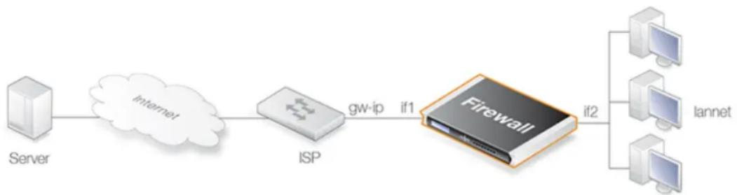
flowchart
graph LR
    Server --> Internet
    Internet --> ISP
    ISP --> gw_ip
    gw_ip --> if1
    if1 --> Firewall
    Firewall --> lannet
    Firewall --> PC1
    Firewall --> PC2
    Firewall --> PC3
Figure 4.24. Non-transparent Mode Internet Access
The non-switch route usually needed to allow Internet access would be:
| Route type Interface Destination Gateway | |||
| Non-switch if1 all-nets gw-ip |
Now suppose the D-Link firewall is to operate in transparent mode between the users and the ISP. The illustration below shows how, using switch routes, the firewall is set up to be transparent between the internal physical Ethernet network (pn2) and the Ethernet network to the ISP's gateway (pn1). The two Ethernet networks are treated as a single logical IP network in Transparent Mode with a common address range (in this example 192.168.10.0/24).
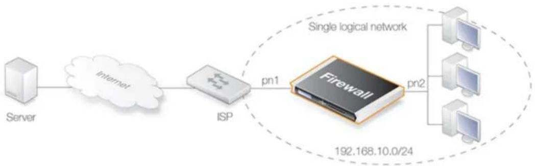
flowchart
graph LR
    Server --> Internet
    Internet --> ISP
    ISP --> firewall
    firewall --> PC1["PC1"]
    firewall --> PC2["PC2"]
    firewall --> PC3["PC3"]
    firewall --> firewall2["Firewall"]
    firewall2 --> SingleLogicalNetwork
    style firewall fill:#f9f,stroke:#333
    style single logicalnetwork fill:#ccf,stroke:#333
Figure 4.25. Transparent Mode Internet Access
In this situation, any "normal" non-switch all-nets routes in the routing table should be removed and replaced with an all-nets switch route (not doing this is a common mistake during setup). This switch route will allow traffic from the local users on Ethernet network pn2 to find the ISP gateway.
These same users should also configure the Internet gateway on their local computers to be the ISPs gateway address. In non-transparent mode the user's gateway IP would be the firewall's IP address but in transparent mode the ISP's gateway is on the same logical IP network as the users and will therefore be gw-ip.
NetDefendOS May Also Need Internet Access
The D-Link firewall also needs to find the Internet if it is to perform NetDefendOS functions such as DNS lookup, Web Content Filtering or Anti-Virus and IDP updating. To allow this, individual "normal" non-switch routes need to be set up in the routing table for each IP address specifying the interface which leads to the ISP and the ISPs gateway IP address.
If the IPv4 addresses that need to be reached by NetDefendOS are 85.12.184.39 and 194.142.215.15 then the complete routing table for the above example would be:
| Route type Interface Destination Gateway | |||
| Switch | if1 all-nets | ||
| Switch | if2 all-nets | ||
| Non-switch if1 85.12.184.39 gw-ip | |||
| Non-switch if1 194.142.215.15 | gw-ip | ||
The appropriate IP rules will also need to be added to the IP rule set to allow Internet access
through the D-Link firewall.
Grouping IP Addresses
It can be quicker when dealing with many IP addresses to group all the addresses into a single group IP object and then use that object in a single defined route. In the above example, 85.12.184.39 and 194.142.215.15 could be grouped into a single object in this way.
Using NAT
NAT should not be enabled for NetDefendOS in Transparent Mode since, as explained previously, the D-Link firewall is acting like a level 2 switch and address translation is done at the higher IP OSI layer.
The other consequence of not using NAT is that IP addresses of users accessing the Internet usually need to be public IPv4 addresses.
If NATing needs to be performed in the example above to hide individual addresses from the Internet, it would have to be done by a device (possibly another D-Link firewall) between the 192.168.10.0/24 network and the Internet. In this case, internal, private IPv4 addresses could be used by the users on Ethernet network pn2.
4.9.3. A Transparent Mode Use Case
In the use case illustrated below, a D-Link firewall in transparent mode is placed between an Internet access router and the internal network. The router is used to share the Internet connection with a single public IPv4 address. The internal NATed network behind the firewall is in the 10.0.0.0/24 address space. Clients on the internal network are allowed to access the Internet via the HTTP protocol. The actual setup steps are listed in the example below.
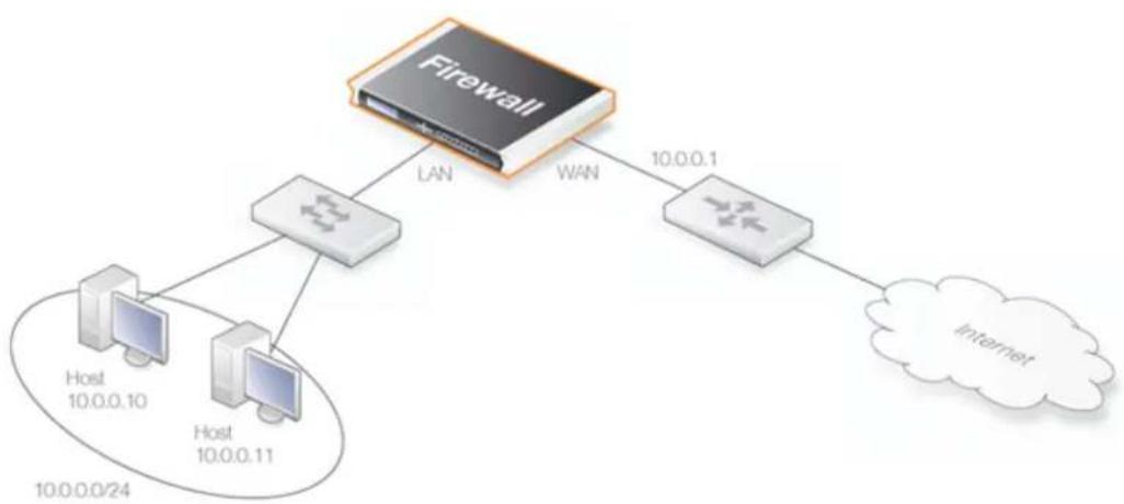
flowchart
graph TD
    A["Firewall"] -->|LAN| B["Host 10.0.0.10"]
    A -->|LAN| C["Host 10.0.0.11"]
    A -->|WAN| D["Router 10.0.0.1"]
    D --> E["Internet"]
Figure 4.26. Transparent Mode Use Case
Example 4.21. A Transparent Mode Use Case
Command-Line Interface
Configure the wan interface:
gw-world:/> set Interface Ethernet wan
    IP=10.0.0.1
    Network=10.0.0.0/24
    DefaultGateway=10.0.0.10
    AutoSwitchRoute=Yes
Configure the lan interface:
gw-world:/> set Interface Ethernet lan
IP=10.0.0.2
Network=10.0.0.0/24
AutoSwitchRoute=Yes
Add the IP rule:
gw-world:/> add IPRule Action=Allow
SourceInterface=lan
SourceNetwork=10.0.0.0/24
DestinationInterface=any
DestinationNetwork=all-nets
Service=http
Name=http_allow
Web Interface
Configure the wan interface:
- Go to: Network > Interfaces and VPN > Ethernet
- Select the wan interface
- Now enter:
• IP Address: 10.0.0.1
• Network: 10.0.0.0/24 - Default Gateway: 10.0.0.10
- Transparent Mode: Enable
4. Click OK
Configure the lan interface:
- Go to: Network > Interfaces and VPN > Ethernet
- Select the lan interface
- Now enter:
- IP Address: 10.0.0.2
• Network: 10.0.0.0/24 - Transparent Mode: Enable
4. Click OK
Configure the rules:
-
Go to: Policies > Firewalling > Main IP Rules > Add > IP Rule
-
Now enter:
-
Name: http_allow
- Action: Allow
• Service: http - Source Interface: Ian
- Destination Interface: any
• Source Network: 10.0.0.0/24 -
Destination Network: all-nets
-
Click OK
4.9.4. Spanning Tree BPDU Support
NetDefendOS includes support for relaying the Bridge Protocol Data Units (BPDUs) across the D-Link firewall. BPDU frames carry Spanning Tree Protocol (STP) messages between layer 2 switches in a network. STP allows the switches to understand the network topology and avoid the occurrences of loops in the switching of packets.
The diagram below illustrates a situation where BPDU messages would occur if the administrator enables the switches to run the STP protocol. Two D-Link firewalls are deployed in transparent mode between the two sides of the network. The switches on either side of the firewall need to communicate and require NetDefendOS to relay switch BPDU messages in order that packets do not loop between the firewalls.
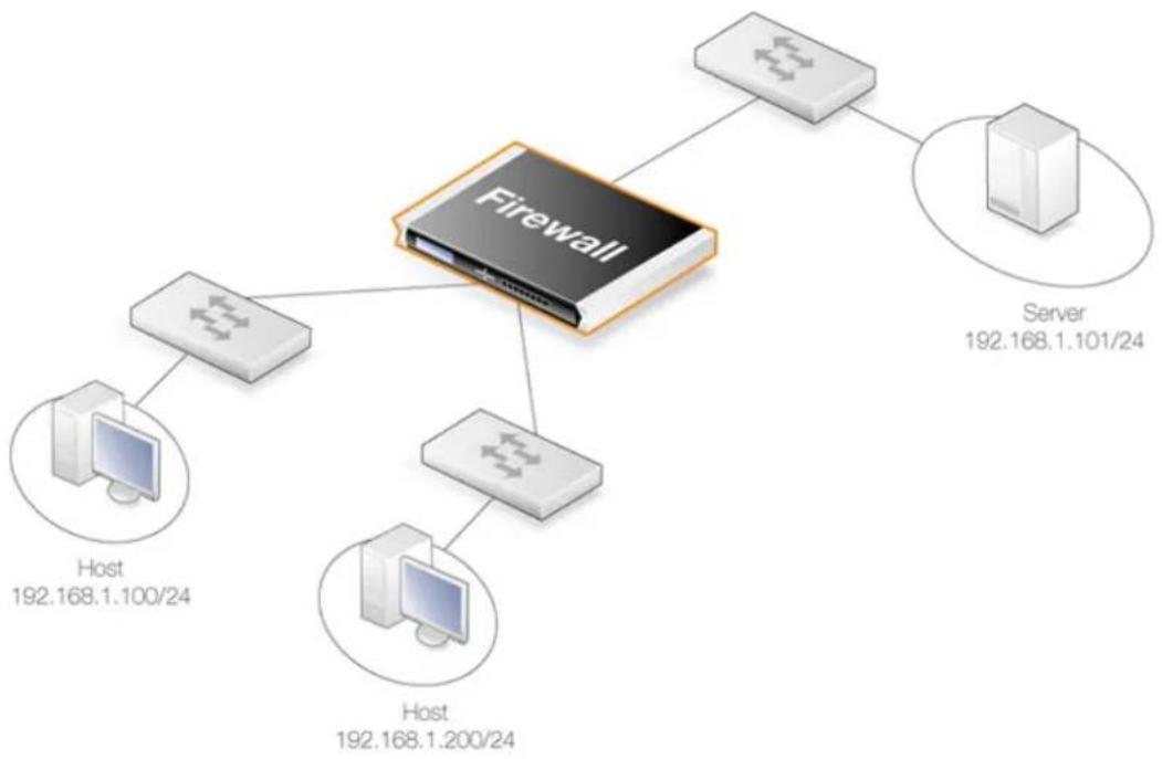
flowchart
graph TD
    Firewall["Firewall"] --> Server["Server 192.168.1.101/24"]
    Firewall --> Host1["Host 192.168.1.100/24"]
    Firewall --> Host2["Host 192.168.1.200/24"]
    Firewall --> Server3["Server 192.168.1.101/24"]
Figure 4.27. An Example BPDU Relaying Scenario
Implementing BPDU Relaying
The NetDefendOS BDPU relaying implementation only carries STP messages. These STP messages can be of three types:
• Normal Spanning Tree Protocol (STP)
• Rapid Spanning Tree Protocol (RSTP)
• Multiple Spanning Tree Protocol (MSTP)
• Cisco proprietary PVST+ Protocol (Per VLAN Spanning Tree Plus)
NetDefendOS checks the contents of BDPU messages to make sure the content type is supported. If it is not, the frame is dropped.
Enabling/Disabling BPDU Relaying
BPDU relaying is disabled by default and can be controlled through the advanced setting Relay Spanning-tree BPDUs. Logging of BPDU messages can also be controlled through this setting. When enabled, all incoming STP, RSTP and MSTP BPDU messages are relayed to all transparent interfaces in the same routing table, except the incoming interface.
4.9.5. MPLS Pass Through
Multi-protocol Label Switching (MPLS) is a standard that allows the attaching of labels to IP packets to provide information about the packet's eventual destination. The router that initially attached the MPLS label is known as the ingress router.
Network nodes that support MPLS can then use this attached information to route packets
without needing to perform route lookups and therefore increase processing speed. In addition to overall faster traffic movement, MPLS also makes it easier to manage Quality of Service (QoS).
MPLS is considered to be "multi-protocol" because it works with the Internet Protocol, Asynchronous Transport Mode (ATM) and frame relay network. When considered in reference to the OSI network model, MPLS allows packets to be forwarded at the layer two level rather than at the layer three level and for this reason it is said to operate at the two and a half level.
NetDefendOS MPLS Support
NetDefendOS supports MPLS Pass Through. This is relevant in transparent mode scenarios where the MPLS labeled packets are allowed to traverse the firewall. NetDefendOS can optionally validate the integrity of these MPLS packets and the administrator can change the advanced setting Relay MPLS to specify the specific action to be taken. The possible values for this setting are:
- Ignore - Verify packets and allow all verified MPLS labeled packets to pass silently. Packets that fail verification are logged.
- Log - Verify packets and allow all verified MPLS packets to pass as well as being logged. Packets that fail verification are also logged.
- Drop - Silently drop all MPLS packets without verification or logging.
- Drop/Log - Drop all MPLS packets without verification and log these drops.
4.9.6. Advanced Settings for Transparent Mode
CAM To L3 Cache Dest Learning
Enable this if the firewall should be able to learn the destination for hosts by combining destination address information and information found in the CAM table.
Default: Enabled
Decrement TTL
Enable this if the TTL should be decremented each time a packet traverses the firewall in transparent mode.
Default: Disabled
Dynamic CAM Size
This setting can be used to manually configure the size of the CAM table. Normally Dynamic is the preferred value to use.
Default: Dynamic
CAM Size
If the Dynamic CAM Size setting is not enabled then this is the maximum number of entries in each CAM table.
Default: 8192
Dynamic L3C Size
Allocate the L3 Cache Size value dynamically.
Default: Enabled
L3 Cache Size
This setting is used to manually configure the size of the Layer 3 Cache. Enabling Dynamic L3C Size is normally preferred.
Default: Dynamic
Relay Spanning-tree BPDUs
When set to Ignore all incoming STP, RSTP and MSTP BPDUs are relayed to all transparent interfaces in the same routing table, except the incoming interface. Options:
- Ignore - Let the packets pass but do not log
• Log - Let the packets pass and log the event - Drop - Drop the packets
- DropLog - Drop packets log the event
Default: Drop
Relay MPLS
When set to Ignore all incoming MPLS packets are relayed in transparent mode. Options:
- Ignore - Let the packets pass but do not log
- Log - Let the packets pass and log the event
- Drop - Drop the packets
- DropLog - Drop packets log the event
Default: Drop
Chapter 5: DHCP Services
This chapter describes DHCP services in NetDefendOS.
• Overview, page 408
• IPv4 DHCP Client, page 410
• IPv4 DHCP Server, page 412
• IPv4 DHCP Relay, page 419
• IP Pools, page 425
• DHCPv6, page 428
5.1. Overview
Dynamic Host Configuration Protocol (DHCP) is a protocol that allows network administrators to automatically assign IP numbers to computers on a network. It can perform this function both for IPv4 and IPv6 addresses.
IP Address Assignment
A DHCP Server implements the task of assigning IP addresses to DHCP clients. These addresses come from a predefined IP address pool which DHCP manages. When a DHCP server receives a request from a DHCP client, it returns the configuration parameters (such as an IP address, a MAC address, a domain name, and a lease for the IP address) to the client in a unicast message.
DHCP Leases
Compared to static assignment, where the client owns the address, dynamic addressing by a DHCP server leases the address to each client for a predefined period of time. During the lifetime of a lease, the client has permission to keep the assigned address and is guaranteed to have no address collision with other clients.
Lease Expiration
Before the expiration of the lease, the client needs to renew the lease from the server so it can keep using the assigned IP address. The client may also decide at any time that it no longer
wishes to use the IP address it was assigned, and may terminate the lease and release the IP address. The lease time can be configured in a DHCP server by the administrator.
5.2. IPv4 DHCP Client
In a D-Link firewall, any Ethernet interface or VLAN interface can act as an IPv4 DHCP client so that the IPv4 address and network for the interface can be assigned by an external DHCP server. This feature can be enabled or disabled by changing the Enable DHCP property for the interface object in the NetDefendOS configuration. The default settings are as follows:
- Ethernet interfaces - The default setting for Ethernet interfaces depends on the hardware platform. For the NetDefendOS product series, consult the relevant hardware guide.
• VLAN interfaces - DHCP is always disabled by default for VLAN interfaces.

Important: IPv4 DHCP clients are not supported in HA clusters
The IPv4 DHCP client is not supported for interfaces in a NetDefendOS high availability cluster. If it is enabled in a cluster, this will result in the error message Shared HA IP address not set when trying to commit the configuration.
As soon as DHCP is enabled on an interface and the changed NetDefendOS configuration is deployed, the following will occur:
• A DHCP lease request is issued on the DHCP enabled interface.
• A listening DHCP server will issue a lease to the interface.
- NetDefendOS will change the IPv4 address and network of the interface to become the values in the lease.
- The NetDefendOS address book objects associated with the interface will lose their original values and take on the value 0.0.0.0 for the IPv4 address and 0.0.0.0/0 for the IPv4 network. The address book objects will not show the DHCP assigned values although these will be shown when examining the properties of the interface configuration object.
The same process of requesting a lease will also take place if NetDefendOS is restarted. If the DHCP is subsequently disabled on an interface, the administrator will need to manually assign the IPv4 address and network.

Note: The IP address icon changes in the Web Interface
When IP addresses are allocated to an interface, the IPv4 address and network icons change in the Web Interface display of interface properties so they have an asterisk in the lower left corner.
The examples below shows how the option is enabled for an Ethernet interface. The procedure is almost identical for a VLAN interface.
Example 5.1. Enabling an Ethernet Interface as a DHCP Client
This example shows how to enable the Ethernet interface If1 as a DHCP client.
Command-Line Interface
gw-world:/> set Interface Ethernet If1 DHCPEnabled=Yes
Web Interface
- Go to: Network > Ethernet > If1
- Select Enable DHCP
- Click OK
5.3. IPv4 DHCP Server
A NetDefendOS DHCP Server object assigns and manages IP addresses taken from a specified address pool. These servers are not limited to serving a single range of IP addresses but can use any IP address range that can be specified by a NetDefendOS IP address object.
The DHCPServer object is used for IPv4 addresses and the DHCPv6Server object is used for IPv6 objects. The two are configured in very similar ways although the underlying implementations are very different. The IPv6 server also provides several options which do not exist for IPv4. DHCP relay and IP pools cannot currently be used with IPv6 DHCP.
Multiple DHCP Servers
The administrator has the ability to set up one or more logical IPv4 or IPv6 DHCP servers in NetDefendOS. Filtering of DHCP client requests to different DHCP servers is based on a combination of the following DHCP Server properties:
- Interface
Each NetDefendOS interface can have, at most, one single logical DHCP server associated with it. In other words, NetDefendOS can provision DHCP clients using different address ranges depending on what interface they are located on.
- Relay Filter
The value of the Relay Filter property is also used to determine which DHCP Server object to use. The default value of all-nets means that all addresses are accepted and only the interface is considered in making a DHCP server selection. The other options for this parameter are described further below.
Searching the Server List
Multiple DHCP servers form a list as they are defined, the last defined being at the top of the list. When NetDefendOS searches for a DHCP server to service a request, it goes through the list from top to bottom and chooses the first server with a matching combination of interface and relayer IP filter value. If there is no match in the list then the request is ignored.
The DHCP server ordering in the list can, of course, be changed through one of the user interfaces.
Setting the Relay Filter Property
As explained above, the DHCP Server object used for a client is selected based on a match of both the Interface and Relay Filter properties of the object. A DHCP Server object must have a Relay Filter value specified and the possible values are the following:
· 0.0.0.0/0
The default value is 0.0.0.0/0 (all-nets). This means all DHCP requests will match this filter value regardless if the DHCP requests comes from a client on the local network or has arrived via a DHCP relayer.
• A value of 0.0.0.0
The value 0.0.0.0 will match DHCP requests that come from a local client only. DHCP requests that have been relayed by a DHCP relayer will be ignored.
- A specific IP address.
This is the IP address of the DHCP relayer through which the DHCP request has come. Requests from local clients or other DHCP relayers will be ignored.
IPv4 DHCP Options
The following options can be configured for a DHCP server:
General Parameters
Name A symbolic name for the server. Used as an interface reference but also used as a reference in log messages.
Interface Filter The source interface on which NetDefendOS will listen for DHCP requests. This can be a single interface or a group of interfaces.
Relay Filter A filter for the relay address. The possible values for this and their meanings are listed earlier in this section.
IP Address Pool An IP range, group or network that the DHCP server will use as an IP address pool for handing out DHCP leases.
Netmask The netmask which will be sent to DHCP clients.
Optional Parameters
Default GW This specifies what IP should be sent to the client for use as the default gateway (the router to which the client connects).
Domain The domain within which users are situated. When a user types a simple string into a browser instead of a valid URL, the domain property value can be appended by the browser to form a URL. For example, if the Domain value is "example.com", when the user types just the word "wiki", the browser can try the URL "wiki.example.com".
Lease Time The time, in seconds, that a DHCP lease is provided. After this time the DHCP client must renew the lease.
Primary/Secondary DNS The IP of the primary and secondary DNS servers.
Primary/Secondary NBNS/WINS IP of the Windows Internet Name Service (WINS) servers that are used in Microsoft environments which uses the NetBIOS Name Servers (NBNS) to assign IP addresses to NetBIOS names.
Next Server Specifies the IP address of the next server in the boot process. This is usually a TFTP server.
DHCP Server Advanced Settings
There are two advanced settings which apply to all DHCP servers:
- Auto Save Policy
The policy for saving the lease database to disk. The options are:
i. Never - Never save the database.
ii. ReconfShut - Save the database on a reconfigure or a shutdown.
iii. ReconfShutTimer - Save the database on a reconfigure or a shutdown and also periodically. The amount of time between periodic saves is specified by the next parameter, Lease Store Interval.
- Lease Store Interval
The number of seconds between auto saving the lease database to disk. The default value is 86400 seconds.
Example 5.2. Setting up an IPv4 DHCP server
This example shows how to set up a DHCP server called DHCPServer1 which assigns and manages IP addresses from an IPv4 address pool called DHCPRange1.
This example assumes that an IP range for the DHCP Server has already been created.
Command-Line Interface
gw-world:/> add DHCPServer DHCPServer1
Interface=lan
IPAddressPool=DHCPRange1
Netmask=255.255.255.0
Web Interface
- Go to: Network > Network Services > DHCP Servers > Add > DHCPServer
-
Now enter:
-
Name: DHCPServer1
-
Interface Filter: Ian
• IP Address Pool: DHCPRange1
• Netmask: 255.255.255.0 -
Click OK
Displaying IP to MAC Address Mapping
To display the mappings of IP addresses to MAC addresses that result from allocated DHCP leases, the dhcpserver command can be used. Below, is some typical output:
gw-world:/> dhcpserver -show -mappings
DHCP server mappings:
Client IP Client MAC Mode
10.4.13.240 <00-1e-0b-a0-c6-5f> ACTIVE (STATIC)
10.4.13.241 <00-0c-29-04-f8-3c> ACTIVE (STATIC)
10.4.13.242 <00-1e-0b-aa-ae-11> ACTIVE (STATIC)
10.4.13.243 <00-1c-c4-36-6c-c4> INACTIVE (STATIC)
10.4.13.244 <00-00-00-00-02-14> INACTIVE (STATIC)
10.4.13.254 <00-00-00-00-02-54> INACTIVE (STATIC)
10.4.13.1 <00-12-79-3b-dd-45> ACTIVE
10.4.13.2 <00-12-79-c4-06-e7> ACTIVE
10.4.13.3 [00-a0-f8-23-45-a3] ACTIVE
10.4.13.4 [00-0e-7f-4b-e2-29] ACTIVE
When the MAC address is shown surrounded by square brackets ([.....]) it means that the DHCP server does not track the client using the MAC address but instead tracks the client through a client identifier which the client has given to the server. Angled brackets (<.....>) surrounding the MAC address indicates that tracking is done using the address.
To display all DHCP information use the dhcpserver command with no options. Each individually configured DHCP server is referred to as a Rule which is given a unique number. This number is used to identify which lease belongs to which server in the CLI output. To see just the configured DHCP servers, use the command:
gw-world:/> dhcpserver -show -rules

Tip: The lease database is saved in non-volatile memory
The DHCP lease database is periodically saved to non-volatile memory so that most leases are remembered by NetDefendOS after a system restart. A DHCP advanced setting can be adjusted by the administrator to control how often the database is saved.
The DHCP Server Blacklist
Sometimes, an IP address offered in a lease is rejected by the client. This may because the client detects that the IP address is already in use by issuing an ARP request. When this happens, the NetDefendOS DHCP server adds the IP address to its own blacklist.
The CLI can be used to clear the DHCP server blacklist with the command:
gw-world:/> dhcpserver -release=blacklist
Additional Server Settings
A NetDefendOS DHCP server can have two other sets of objects associated with it:
- Static Hosts.
- Custom Options.
The illustration below shows the relationship between these objects.
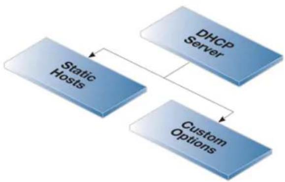
flowchart
graph TD
A["Static Hosts"] --> B["DHCP Server"]
A --> C["Custom Options"]
B --> C
Figure 5.1. DHCP Server Objects
The following sections discuss these two DHCP server options.
5.3.1. Static IPv4 DHCP Hosts
Where the administrator requires a fixed relationship between a client and the assigned IP address, NetDefendOS allows the assignment of a given IP to a specific MAC address. In other words, the creation of a static host.
Static Host Parameters
Many such assignments can be created for a single DHCP server and each object has the following parameters:
Host This is the IP address that will be handed out to the client.
MAC Address This is the MAC address of the client. Either the MAC address can be used or the alternative Client Identified parameter can be used.
Client Identified If the MAC address is not used for identifying the client then the client can send an identifier in its DHCP request. The value of this identifier can be specified as this parameter. The option exists to also specify if the identifier will be sent as an ASCII or Hexadecimal value.
Example 5.3. Static IPv4 DHCP Host Assignment
This example shows how to assign the IPv4 address 192.168.1.1 to the MAC address 00-90-12-13-14-15. The example assumes that the DHCP server DHCPServer1 has already been defined.
Command-Line Interface
- First, change the category to the DHCPServer1 context:
gw-world:/> cc DHCPServer DHCPServer1
- Add the static DHCP assignment:
gw-world:/DHCPServer1> add DHCPServerPoolStaticHost
Host=192.168.1.1
MACAddress=00-90-12-13-14-15
- All static assignments can then be listed and each is listed with an index number:
gw-world:/DHCPServer1> show
<h1 id="comments">Comments</h1>
+ 1 <empty>
- An individual static assignment can be shown using its index number:
gw-world:/DHCPServer1> show DHCPServerPoolStaticHost 1
Property Value
----
Index: 1
Host: 192.168.1.1
MACAddress: 00-90-12-13-14-15
Comments: <empty>
- The assignment could be changed later to IP address 192.168.1.12 with the following command:
gw-world:/DHCPServer1> set DHCPServerPoolStaticHost 1
Host=192.168.1.12
MACAddress=00-90-12-13-14-15
Web Interface
-
Go to: Network > DHCP Services > DHCP Servers > DHCPServer1
-
Select Static Hosts
-
Select Add > Static Host Entry
-
Now enter:
- Host: 192.168.1.1
• MAC: 00-90-12-13-14-15
- Click OK
5.3.2. Custom IPv4 Options
Adding a Custom Option to the DHCP server definition allows the administrator to send specific pieces of information to DHCP clients in the DHCP leases that are sent out.
An example of this is certain switches that require the IP address of a TFTP server from which they can get certain extra information.
Custom Option Parameters
The following parameters can be set for a custom option:
Code This is the code that describes the type of information being sent to the client. A large list of possible codes exists.
Type This describes the type of data which will be sent. For example, if the type is String then the data is a character string.
Data This is the actual information that will be sent in the lease. This can be one value or a comma separated list.
The meaning of the data is determined by the Code and Type. For example, if the code is set to 66 (TFTP server name) then the Type could be String and the Data would then be a site name such as tftp.example.com.
There is a large number of custom options which can be associated with a single DHCP server and these are described in:
RFC 2132 - DHCP Options and BOOTP Vendor Extensions
The code is entered according to the value specified in RFC 2132. The data associated with the code is first specified in NetDefendOS as a Type followed by the Data.
5.4. IPv4 DHCP Relay

Note
DHCP relay is a feature which is currently only available with IPv4 DHCP.
The DHCP Propagation Problem
With DHCP, clients locate the DHCP servers using broadcast messages. However, broadcasts are normally only propagated across the local network. This means that the DHCP server and client need to be on the same physical network. In a large scale network topology, this means there would have to be a different DHCP server on every network. This problem is solved by using a DHCP relayer.
The DHCP Relayer Solution
A DHCP relayer takes the place of the DHCP server in the local network and acts as a link between the client and remote DHCP server. It intercepts requests coming from clients and relays them to one of more DHCP servers. The DHCP server then responds to the relayer, which forwards the response back to the client. DHCP relayers can also relay BOOTP packets and can sometimes be referred to as BOOTP relay agents.
The DHCP Relay Object
DHCP relaying is configured in NetDefendOS by creating a DHCP Relay object. This object has the following general properties:
- Name
A suitable configuration name for the object.
• Action
This can be one of the following settings:
i. Ignore
DHCP requests are ignored. This is the default.
ii. Relay
DHCP (and BOOTP) packets are relayed to the configured DHCP server(s) and replies are relayed back.
iii. BOOTPForward
Only BOOTP (Bootstrap Protocol) packets will be relayed.
- Source Interface
The interface on which the relayer will listen for requests. This can be set to an Interface Group object to specify multiple interfaces. This property is required for relaying.
• DHCP Server to relay to
The IPv4 address of a DHCP server to relay client requests to. This property is required for
relaying.
• Additional DHCP Servers
It is optionally possible to relay to more than one DHCP server. A total of two extra DHCP server IP addresses can be specified, in addition to the first server.
When relaying is performed, NetDefendOS will relay exactly the same client request to all the configured servers at the same time. All replies will be relayed back to the client and it is up to the client to decide how these are handled.
• Allowed IP offers from server
An optional range of acceptable IP addresses in the relayed leases. This could be specified as a network (for example, 203.0.113.0/24) or a range (for example, 203.0.113.0-203.0.113.100). By default, all IPv4 addresses are allowed.
Leases that fall out of the specified range will be rejected.
Other optional properties for the DHCP Relayer object are discussed next.
Setting the Source IP of Relayed DHCP Traffic
For relayed DHCP traffic, the option exists in NetDefendOS to use one of the following as the source IPv4 address of DHCP traffic relayed to a server:
- The IPv4 address of the interface on which it listens for client requests. This is the default setting and ensures that the DHCP server knows which network a request is coming from. This can be important if the DHCP server is set up to allocate IP addresses based on the source IP of a request.
- The IPv4 address of the interface from which it sends out the relayed request to the server. This would be used where the listening interface IP for the relayer is not relevant, or in the case of VLANs, might not be available.
This setting can be found under the Options tab of the DHCP Relayer object in the Web Interface.
Core Routing Does Not Apply
Although NetDefendOS interface IPs are usually core routed, for relayed DHCP requests, core routing does not apply. Instead, the interface is the source interface and not the core interface.
Adding Dynamic Routes for Relayed DHCP Leases
The Add dynamic routes for this relayed DHCP lease property (found under the Add Route tab in the Web Interface) is disabled by default so no routes are added for IP addresses allocated by a DHCP server. This is acceptable if a static route is already set up which routes on the correct interface the address range handed out to clients by the DHCP server(s).
However, sometimes having a single static route is not a suitable routing solution, particularly if there are clients on multiple networks sending DHCP requests through a single relayer. In this case, it can be easier to enable adding routes automatically for each client address allocated. The danger is that large numbers of clients can cause excessive NetDefendOS system overhead if a large number of routes are added.
Setting the Parameters of Added Routes
If the Add dynamic routes for this relayed DHCP lease property is enabled it is also possible to set any of the following properties of the routes added, if required:
- Routing Table - Which routing table the route is to be added to (default is main)
- Local IP - NetDefendOS will respond to ARP queries sent to this address. The use of this setting is explained further in Section 4.2.1, "Static Routing in NetDefendOS".
• Gateway - This would be used if relayed clients are behind a routing device.
Setting the Maximum Relaying Clients Per Interface
The optional property Max relays per interface can be used to specify the maximum number of clients that are permitted to send relayed DHCP requests through a single interface.
Using the Proxy ARP Options
In some scenarios, it is necessary to add a route for each DHCP lease using the property described above. Consider the layout shown below, where a single DHCP server is handing out IPs in the same network range via relay by NetDefendOS to two clients on the separate interfaces If1 and If2.
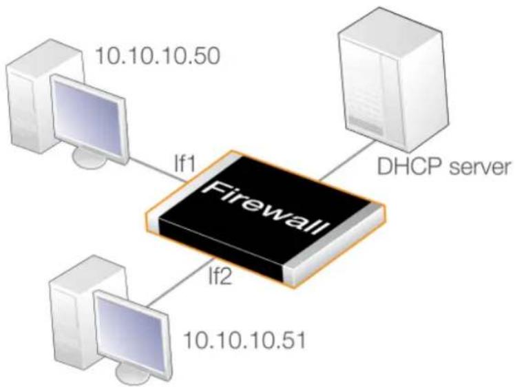
flowchart
graph TD
A["10.10.10.50"] -->|If1| B["Firewall"]
C["10.10.10.51"] -->|If2| B
D["DHCP server"] --> B
Figure 5.2. DHCP Relay with Proxy ARP
In this case, adding a route automatically for each lease is necessary. In addition, the two clients will get IP addresses from the same network range and can be regarded as being on the same network. However, to be able to talk to each other, the Proxy ARP Interfaces property of the DHCP Relay object must be set to the interfaces If1 and If2 so that the IP addresses handed out by the DHCP server can be found by each client.
PXE Support and Allowing NULL Offers
The Preboot Execution Environment (PXE) makes use of DHCP to enable booting of clients from a server across a network. PXE makes use of a NULL Offer which is a DHCP server response offering the IP address 0.0.0.0 (no address offered).
By default, NetDefendOS will not relay NULL offers. To enable relaying, the following steps are required:
- Create the DHCP Relay object and set the Action to be Relay. This will allow a number of options to be set.
- Enable the option Allow NULL offers.
Example 5.4. Setting up a DHCP Relayer
This example allows clients on NetDefendOS VLAN interfaces to obtain IP addresses from a DHCP server.
It is assumed the firewall is already configured with VLAN interfaces vlan1 and vlan2. The clients on both these interfaces will generate DHCP requests which be relayed to a single DHCP server. The DHCP server's IP address is defined in the NetDefendOS address book as the address object ip-dhcp.
NetDefendOS will also automatically add a route for the IP address allocated to the client by the DHCP relaying process.
Command-Line Interface
- A. Add the VLAN interfaces vlan1 and vlan2 to a new interface group called ipgrp-dhcp:
gw-world:/> add Interface InterfaceGroup ipgrp-dhcp Members=vlan1,vlan2
- B. Create a DHCP relayer object called as vlan-to-dhcpserver:
gw-world:/> add DHCPRelay vlan-to-dhcpserver
Action=Relay
TargetDHCPServer=ip-dhcp
SourceInterface=ipgrp-dhcp
AddRoute=Yes
Web Interface
A. Add the VLAN interfaces vlan1 and vlan2 to a new interface group called ipgrp-dhcp:
-
Go to: Network > Interfaces and VPN > Interface Groups > Add > Interface Group
-
Now enter:
- Name: ipgrp-dhcp
- Interfaces: select vlan1 and vlan2 from the Available list and put them into the Selected list.
- Click OK
B. Create a DHCP relayer object called as vlan-to-dhcpserver:
-
Go to: Network > DHCP Services > DHCP Relay > Add
-
Now enter:
• Name: vlan-to-dhcpserver
• Action: Relay
- Source Interface: ipgrp-dhcp
• DHCP Server to relay to: ip-dhcp
• Allowed IP offers from server: all-nets
-
Under the Add Route tab, check Add dynamic routes for this relayed DHCP lease
-
Click OK
DHCP Relay Advanced Settings
The following advanced settings are available with DHCP relaying.
Max Transactions
Maximum number of transactions at the same time.
Default: 32
Transaction Timeout
For how long a dhcp transaction can take place.
Default: 10 seconds
Max PPM
How many dhcp-packets a client can send to through NetDefendOS to the dhcp-server during one minute.
Default: 500 packets
Max Hops
How many hops the dhcp-request can take between the client and the dhcp-server.
Default: 5
Max lease Time
The maximum lease time allowed by NetDefendOS. If the DHCP server has a higher lease time, it will be reduced down to this value.
Default: 10000 seconds
Max Concurrent Relays
How many relays that can be active at the same time.
Default: 256
Auto Save Policy
What policy should be used to save the relay list to the disk, possible settings are Disabled, ReconfShut, or ReconfShutTimer.
Default: ReconfShut
Auto Save Interval
How often, in seconds, should the relay list be saved to disk if DHCPServer_SaveRelayPolicy is set to ReconfShutTimer.
Default: 86400
5.5. IP Pools

Note
IP pools can currently only be used with IPv4 DHCP.
Overview
An IP pool is used to offer other subsystems access to a cache of DHCP IP addresses. These addresses are gathered into a pool by internally maintaining a series of DHCP clients (one DHCP client per IP address). More than one DHCP server can be used by a pool and can either be external or be local DHCP servers defined in NetDefendOS itself. Multiple IP Pools can be set up with different identifying names.
External DHCP servers can be specified in one of two ways:
• As the single DHCP server on a specific interface
• One or more can be specified by a list of unique IP address.
IP Pools with Config Mode
A primary usage of IP Pools is with IKE Config Mode which is a feature used for allocating IP addresses to roaming clients connecting through IPsec tunnels. For more information on this see Section 10.3.11, "Config Mode".
Basic IP Pool Options
The basic options available for an IP Pool are:
DHCP Server behind interface Indicates that the IP pool should use the DHCP server(s) residing on the specified interface.
Specify DHCP Server Address Specify DHCP server IP(s) in preferred ascending order to be used. This option is used instead of the behind interface option.
Using the IP loopback address 127.0.0.1 indicates that the DHCP server is NetDefendOS itself.
Server filter Optional setting used to specify which servers to use. If unspecified any DHCP server on the interface will be used. The order of the provided address or ranges (if multiple) will be used to indicate the preferred servers.
Client IP filter This is an optional setting used to specify which offered IPs are acceptable. In most cases this will be set to the default of all-nets so all addresses will be acceptable. Alternatively, a set of acceptable IP ranges can be specified.
This filter option is used in the situation where there may be a DHCP server response with an unacceptable IP address.
Advanced IP Pool Options
Advanced options available for IP Pool configuration are:
| Routing Table | The routing table to be used for lookups when resolving the destination interfaces for the configured DHCP servers. |
| Receive Interface | A "simulated" virtual DHCP server receiving interface. This setting is used to simulate a receiving interface when an IP pool is obtaining IP addresses from internal DHCP servers. This is needed since the filtering criteria of a DHCP server includes aReceive Interface.An internal DHCP server cannot receive requests from the IP pool subsystem on an interface since both the server and the pool are internal to NetDefendOS. This setting allows such requests from a pool to appear as though they come from a particular interface so that the relevant DHCP server will respond. |
| MAC Range | A range of MAC addresses that will be used to create "fake" DHCP clients. Used when the DHCP server(s) map clients by the MAC address. An indication of the need for MAC ranges is when the DHCP server keeps giving out the same IP for each client. |
| Prefetch leases | Specifies the number of leases to keep prefetched. Prefetching will improve performance since there will not be any wait time when a system requests an IP (while there exists prefetched IPs). |
| Maximum free | The maximum number of "free" IPs to be kept. Must be equal to or greater than the prefetch parameter. The pool will start releasing (giving back IPs to the DHCP server) when the number of free clients exceeds this value. |
| Maximum clients | Optional setting used to specify the maximum number of clients (IPs) allowed in the pool. |
| Sender IP | This is the source IP to use when communicating with the DHCP server. |
Memory Allocation for Prefetched Leases
As mentioned in the previous section, the Prefetched Leases option specifies the size of the cache of leases which is maintained by NetDefendOS. This cache provides fast lease allocation and can improve overall system performance. It should be noted however that the entire prefetched number of leases is requested at system startup and if this number is too large then this can degrade initial performance.
As leases in the prefetch cache are allocated, requests are made to DHCP servers so that the cache is always full. The administrator therefore has to make a judgment as to the optimal initial size of the prefetch cache.
Listing IP Pool Status
The CLI command ippools can be used to look at the current status of an IP pool. The simplest form of the command is:
gw-world:/> ippool -show
This displays all the configured IP pools along with their status. The status information is divided into four parts:
• Zombies - The number of allocated but inactive addresses.
• In progress - The number of addresses that in the process of being allocated.
• Free maintained in pool - The number of addresses that are available for allocation.
• Used by subsystems - The number of addresses that are allocated and active.
Other options in the ippool command allow the administrator to change the pool size and to free up IP addresses. The complete list of command options can be found in the CLI Reference Guide.
Example 5.5. Creating an IP Pool
This example shows the creation of an IP Pool object that will use the DHCP server on IP address 28.10.14.1 with 10 prefetched leases. It is assumed that this IP address is already defined in the address book as an IP object called ippool_dhcp
Command-Line Interface
gw-world:/> add IPPool ip_pool_1
DHCPServerType=ServerIP
ServerIP=ippool_dhcp
PrefetchLeases=10
Web Interface
- Go to: Objects > IP Pools > Add > IP Pool
- Now enter Name: ip_pool_1
- Select Specify DHCP Server Address
- Add ippool_dhcp to the Selected list
- Select the Advanced tab
- Set Prefetched Leases to 10
- Click OK
5.6. DHCPv6
NetDefendOS supports DHCPv6, the equivalent of IPv4 DHCP for IPv6. This is described in the two sections that follow:
• Section 5.6.1, "DHCPv6 Client"
• Section 5.6.2, "DHCPv6 Server"
5.6.1. DHCPv6 Client
Overview
Any interface can be configured to be a DHCPv6 client. This means that whenever NetDefendOS restarts or when the DHCPv6 enabled configuration is saved and activated, the interface will automatically try to retrieve an IPv6 lease from a connected DHCPv6 server. Only the following interface types support the DHCPv6 client function:
- Ethernet interfaces.
- VLAN interfaces.
- Link Aggregation interfaces.
This section will use the generic term interface to mean any of the above types.

Important: DHCPv6 clients are not supported in HA clusters
The DHCPv6 client is not supported for interfaces in a NetDefendOS high availability cluster. If it is enabled for an interface, this will result in an error message when trying to commit the configuration.
Addresses Received in a Server Lease
The lease received from a DHCPv6 server will contain the following:
• An IPv6 address for the interface.
- The addresses of up to three IPv6 DNS servers. NetDefendOS will only read the first two. The third will be discarded.
As explained later in the section, the IPv6 network address and IPv6 gateway address can also be automatically retrieved if the interface property Router Discovery is enabled.
Address Book Objects Created
The following is a list of the IPv6 address book objects that will be created when the DHCP client is enabled on, for example, the if1 interface:
- if1_ip6 - The interface address.
-
if1_dns6_1 - The first IPv6 DNS address in the DHCP lease.
-
if1_dns6_2 - The second IPv6 DNS address in the DHCP lease.
- if1_net6 - The interface network (requires Router Discovery is enabled).
- if1_gw6 - The gateway (requires Router Discovery is enabled).
The DHCP client mechanism not only creates these objects but also assigns them to the relevant property in the interface. Using the Router Discovery option is discussed later in this section.
Enabling DHCPv6
Similar to DHCP with IPv4, DHCPv6 is enabled using the Enable DHCPv6 property for a specific interface. By default, this property is disabled.
In addition, a number of other properties can be optionally specified for an interface:
- Preferred IP
This is a suggestion sent to the DHCPv6 server for what the interface IP should be.
• Preferred Lifetime and Valid Lifetime
These are suggestions sent to the DHCPv6 server for what the lifetimes should be for an IP. The lower limit for these values in NetDefendOS is 7600 seconds and the Valid Lifetime should always be greater than the Preferred Lifetime. The meaning of these two settings is explained further in Section 5.6.2, "DHCPv6 Server".
- Lease Filter
This a range of acceptable IPv6 addresses that can be assigned to the interface. If the offered lease does not contain this address, it is rejected.
- Server Filter
This is a range of IPv6 addresses for servers from which NetDefendOS will accept leases.
The Router Discovery Option
An Ethernet configuration object has an additional property called Router Discovery which is either disabled or enabled.
By default, this option is disabled which means that the DHCPv6 client feature will only set the IPv6 address for the interface and the IPv6 addresses of DNS servers, while the network address and the gateway addresses must be set manually by the administrator.
When the Router Discovery option is enabled, a complete set of client addresses will be provided by the DHCPv6 process including the IPv6 network and the IPv6 gateway address. This is similar to the standard way that IPv4 functions.

Tip: An ISP will have a correct IPv6 connection method
When connecting to an ISP using IPv6, check with the ISP how NetDefendOS should be configured. Using the DHCP client with Router Discovery enabled may be required by the ISP to retrieve the IPv6 address for the ISP's gateway as well as for the IPv6 network.
The Router Discovery option can also be used when automatically configuring the IPv6 address of
the interface, with the DHCP client function disabled. This usage is described in Section 3.2, "IPv6 Support".
Assigned DNS Servers
The lease granted by a DHCPv6 server can contain up to three IPv6 addresses of DNSv6 servers. However, NetDefendOS will only use the first and second of these which are sometimes known as the Primary, and Secondary servers. If a third server is present in the lease it will be ignored.
The DNSv6 addresses obtained from the DHCP server will be stored in two properties of the interface configuration object which are called DHCPv6DNS1 and DHCPv6DNS2.
Created DNS Address Objects
For the first DNSv6 server address in a lease, NetDefendOS will automatically create a new IPv6 address book object with the name
For example, if the interface receiving the DHCPv6 lease is the wan interface then the address book object created for the first lease will be named wan_dns6_1. If the lease contains a second DNSv6 server address, this will be called wan_dns6_2 and so on.
The DNSv6 server addresses can be configured statically for NetDefendOS. If this is done, these manually configured addresses take precedence over addresses received in a lease. However, NetDefendOS will still automatically create the address book objects of the form
Behavior on Lease Expiry
When a DHCP lease ends and is not renewed, any address book objects created by the DHCPv6 mechanism will remain in the address book. However, the values of the address book objects associated with an interface will be affected as follows:
• Network and gateway objects will retain the values that were last allocated by DHCPv6.
• All other objects will be set to the IPv6 unspecified address (::/128).
Example 5.6. DHCPv6 Client Setup
This example shows how to enable DHCPv6 on the wan interface. It is assumed that IPv6 has already been enabled for the interface.
Command-Line Interface
gw-world:/> set Interface Ethernet wan DHCPv6Enabled=Yes
Web Interface
- Go to: Network > Interfaces and VPN > Ethernet
-
Select the wan interface
-
Select Enable DHCPv6 Client
-
Click OK
5.6.2. DHCPv6 Server
NetDefendOS provides the ability to set up one or more DHCPv6 servers. Configuring these is almost identical to configuring an IPv4 DHCP server. However, there are some object properties which are available with DHCPv6 but not with standard IPv4 DHCP. These are as follows:
- Rapid Commit
By default this is disabled. This option makes sense during server solicitation procedure. If the client has included a rapid commit option in the solicit message and the rapid commit setting is enabled then the DHCPv6 server responds to the solicit with a reply. The server commits the assignment of addresses before sending the reply message. The client can assume it has been assigned the addresses in the reply message and does not need to send a request message for those addresses.
If this option is left at the default value of being turned off, the server ignores the rapid commit option and acts as though no rapid commit option were present in the client's solicit message.
- Preference Value
A preference value can be either sent or not sent to the client. If sending it is enabled, the default preference value is zero but this can be manually set to be between 0 and 255.
Setting the preference gives the administrator the ability to prioritize one DHCPv6 server over another. During the server solicitation procedure the client collects received advertise messages from available DHCPv6 servers. The client typically will contact the server that sent the advertise message with the highest server preference value.
A preference value of 255 has the highest priority and once such value is received in an advertise message, the client will immediately begin a client initiated message exchange with the DHCPv6 Server originated the message. This value therefore should only be used in an environment with a single server since other servers will be ignored.
Preferences are often used where the administrator wants one server to be the primary with a higher preference and assigns a lower preference to other backup servers.
- Send Unicast
By default, in negotiations between client and server, the client uses multicast IPv6 address as a destination for all messages. This option enables the inclusion of the server unicast option by a DHCPv6 Server in messages sent to client. Once such an option is received by the client, it can contact the server directly using the server's IPv6 address (which is carried in the server unicast option).
This allows reduction of the network load as well as offloading to other DHCPv6 Servers available on the network.
• Clear Universal Local Bit
When set to a value of Yes, this option will always clear the universal/local bit (u/l bit) in the
IPv6 addresses handed out by the server so that it always has a value of zero. This flags the address as being a locally created one that should not be used universally. This setting applies to /64 networks.
The default value for this setting is No so the bit is not automatically set to zero by NetDefendOS.
• Valid Lifetime and Preferred Lifetime
These are the lifetimes used for IPs sent to a client. The lower limit for these values in NetDefendOS is 7600 seconds and the Valid Lifetime should always be greater than the Preferred Lifetime.
After the Preferred Lifetime expires, the IP could be used for new or existing connections but this should be avoided unless absolutely necessary. For example, an application might have to use the IP because it is part of some unfinished processing. After the Valid Lifetime expires, the IP will become invalid and cannot be used for new or existing connections.

Tip: Speeding up address allocation
If only one DHCPv6 server is configured then the process of IPv6 address allocation can be significantly speeded up by enabling rapid commit and setting the preference value of that server to be 255.
With a preference value of 255, message exchange is triggered as soon as soon as the client receives the solicit message. Rapid commit allows the client to get committed addresses in the reply message during the solicit-reply message exchange with the DHCPv6 server. Together, these can significantly increase the speed of address allocation.
Available Memory Can Limit Lease Allocation
When a DHCPv6 lease is handed out, NetDefendOS stores details of the lease in the firewall's local memory. There is no memory pre-allocated for this list of leases and the amount of memory used can expand from nothing up until the point that all free available memory is exhausted.
When no more memory is available, NetDefendOS will cease to assign new leases and will behave as though there are no free IPs left in the pool. NetDefendOS will signal a general out-of-memory condition and this will appear on the management console. This condition would require a very large number of leases to be allocated.
DHCPv6 Server Setup
The steps for setting up a DHCPv6 server in NetDefendOS are as follows:
- Make sure that IPv6 is enabled for the listening interface of the DHCPv6 server and that there is an IPv6 address assigned to that interface. Doing this is described in Section 3.2, "IPv6 Support".
- Create a new DHCPv6 Server object. This will listen on the specified interface and get the IPv6 addresses handed out from a specified IPv6 Address Pool object.
• The advanced IP setting Multicast HopLimit Min must be set to a value of 1 (the default is 3). - If the firewall which acts as the DHCPv6 server is also going to send out router
advertisements for the server, the following must be configured:
i. Add a Router Advertisement object with the same interface specified as the DCHPv6 server.
ii. Disable the Use Global Settings option for this Router Advertisement object and enable the Managed Flag setting to signal there is a DHCPv6 server on the network. If the DHCPv6 server is providing information about DNS addresses, also enable the Other Config Flag setting.
iii. Add a Prefix object to the Router Advertisement object. This is optional but is normally done. Normally, the prefix specified is the same as the network attached to the DHCPv6 server listening interface.
iv. If it is undesirable that hosts on the network use the defined prefix for stateless auto-configuration, disable the Autonomous Flag setting for the Prefix object. This is probably the case since the DHCPv6 server is being added to the network.
If another device (either a D-Link firewall or third party device) on the network is going to send the router advertisements for the DHCPv6 server, that device must be similarly configured with the settings described above.
Example 5.7. DHCPv6 Server Setup
This example shows how to set up an DHCPv6 server called dhcpv6_server1 on the Ethernet interface lan. Assume that the pool of available IP addresses is already defined by the IPv6 address object dhcpv6_range1.
The server will also use the rapid commit option and will assign itself a preference value of 100. It is assumed in this example that IPv6 has been enabled globally and also for the listening interface lan.
Router advertisements will be generated by the same firewall and the prefix used will be 2001:DB8::/64.
Command-Line Interface
Create the server:
gw-world:/> add DHCPv6Server dhcpv6_server1
Interface=lan
IPv6AddressPool=dhcpv6_range1
RapidCommit=Yes
PreferenceConfigured=Yes
PreferenceValue=100
Set the hop limit to 1:
gw-world:/> set Settings IPSettings HopLimitMinMulticast=1
Create a router advertisement:
gw-world:/> add RouterAdvertisement Name=my_ra
Interface=lan
UseGlobalRASettings=No
RAManagedFlag=Yes
RAOtherConfigFlag=Yes
Change the context to be the router advertisement:
gw-world:/> cc RouterAdvertisement 1
Add the prefix object:
gw-world:/1(my_ra)> add RA_PrefixInformation Name=my_prefix
Prefix=2001:DB8::/64
RAAutonomousFlag=No
Return to the default context:
gw-world:/1(my_ra)> cc
Web Interface
Create the server:
- Go to: Network > Network Services > DHCPv6 Servers > Add > DHCPv6Server
- Now enter:
- Name: dhcpv6_server1
-
Interface Filter: Ian
• IP Address Pool: dhcpv6_range1 -
Select the Options tab
-
Enable Handle Rapid Commit Option
-
Enable Send Preference Option
-
Set the Preference value to be 100
-
Click OK
Set the hop limit to 1:
- Go to: System > Advanced Settings > IP Settings
- Under IPv6 set Multicast HopLimit Min to 1
- Click OK
Create a router advertisement:
- Go to: Network > Routing > Router Advertisements > Add > Router Advertisement
- Now enter:
- Name: my_ra
-
Interface: Ian
-
Select the Advanced tab
-
Disable Use Global Settings
- Enable Managed Flag
- Enable Other Config Flag
- Click OK
Still within the router advertisement definition, add the prefix object:
- Go to: Network > Routing > Router Advertisements > my_ra
- Go to: Prefix Information > Add > Prefix Information
-
Now enter:
-
Name: my_prefix
• Network Prefix: 2001:DB8::/64 -
Disable the setting Autonomous Flag
-
Click OK to save the prefix
-
Click OK to save the advertisement
Static DHCPv6 Hosts
Where the administrator requires a fixed relationship between a client and the assigned IP address, NetDefendOS allows the assignment of a given IPv6 address to a specific MAC address just as it was assigned for IPv4 as described in Section 5.3.1, "Static IPv4 DHCP Hosts".
Example 5.8. Static DHCPv6 Host Assignment
This example shows how to assign the IPv6 address 2001:DB8::1 to the MAC address 00-90-12-13-14-15. The example assumes that the DHCPv6 server dhcpv6_server1 has already been defined.
Command-Line Interface
First, change the category to the dhcp_ipv6_server1 context:
gw-world:/> cc DHCPv6Server dhcpv6_server1
Add the static DHCP assignment:
gw-world:/dhcpv6_server1> add DHCPv6ServerPoolStaticHost
Host=2001:DB8::1
MACAddress=00-90-12-13-14-15
Return to the default context:
gw-world:/dhcpv6_server1> cc
gw-world:/>
Web Interface
-
Go to: Network > Network Services > DHCPv6 Servers > dhcpv6_server1
-
Select Static Hosts
-
Select Add > Static Host Entry
-
Now enter:
- Host: 2001:DB8::1
• MAC: 00-90-12-13-14-15
- Click OK
Chapter 6: Application Layer Security
This chapter describes NetDefendOS security features.
• ALGs, page 438
• Web Content Filtering, page 570
- Email Control, page 591
• Anti-Virus Scanning, page 603
- File Control, page 614
6.1. ALGs
6.1.1. Overview
Low-level packet filtering only inspects the packet headers of protocols such as IP, TCP, UDP, and ICMP. Application Layer Gateways (ALGs) can inspect at a higher OSI level.
An ALG can act as a mediator when accessing commonly used Internet applications outside the protected network, for example with web access, file transfer and multimedia transfer. ALGs provide higher security than packet filtering since they are capable of scrutinizing all traffic for a specific protocol and perform checks at the higher levels of the TCP/IP stack.
ALGs exist for the following protocols in NetDefendOS:
- HTTP
• FTP
• TFTP
• SMTP
• POP3
• IMAP
• PPTP
• SIP
• H.323
• TLS
• DNS

Note: IPv6 based traffic is not supported by some ALGs
Only the HTTP (and LW-HTTP) ALGs have support for IPv6 when used with IP rule set entries that reference IPv6 addresses.
Methods of Deploying an ALG
An ALG is brought into use by associating it with an entry in the IP rule set that triggers on the targeted traffic. This is done using one of the following methods:
- Using IP Policies
This is the recommended method of deploying an ALG because of ease of setup and the additional features that can be applied. Some ALG features are only available when IP policies are used. In addition, some ALGs, such as the ones for DNS and IMAP, can only be deployed using IP policies.
Note that a requirement with this method is that the Service property of the IP policy is assigned a service object which has its Protocol property set to the ALG type (for example, "FTP"). It is usually preferable to create a custom service object for this purpose, although in some cases a predefined service could be used.
- Using IP Rules
With this method, an ALG object for the specific protocol is assigned to a Service object which is in turn assigned to an IP rule. This method of ALG deployment is usually only needed for compatibility with older versions of NetDefendOS.
Predefined ALG objects exist which could be used with IP rules but it is usually better to create a custom ALG object.
This section includes details for setting up ALGs using all the available methods.

Note: ALGs Are Not State Synchronized with HA
No aspect of ALGs are state synchronized in a NetDefendOS high availability cluster. This means that all traffic handled by ALGs will freeze when an HA cluster fails over to the other peer.
However, if the cluster fails back over to the original peer within approximately half a minute, frozen sessions and their associated transfers) should begin working again. Note that such a failover with almost immediate fallback occurs after a reconfigure operation.
Maximum Connection Sessions
The Service used with either an IP policy or IP rule when deploying an ALG has a property called Max Sessions which controls the maximum number of connections that can be handled. The default value for this can vary according to the protocol. For instance, the default value for the HTTP is 200. This means that a total of 200 connections are allowed for the HTTP service across all interfaces. The following is a list of default maximum session values by protocol:

Tip: Maximum sessions for HTTP can sometimes be too low
This default value of the maximum sessions can often be too low for HTTP if there are large number of clients connecting through the D-Link firewall and it is therefore recommended to consider using a higher value in such circumstances.
ALG Changes From NetDefendOS Version 11.01 Onwards
From NetDefendOS version 11.01 onwards, many of the predefined ALG objects have been removed from a new installation of NetDefendOS. Upgrading from an older NetDefendOS will not change the predefined ALG objects and a new installation can manually recreate any missing ALGs if required.
With NetDefendOS version 11.01 and later, it is possible to avoid using most ALG objects directly. This is achieved by using IP Policy objects in place of IP Rule objects. From 11.01 onwards, most predefined Service objects can be used directly with an IP policy and all of the properties previously available in the ALG object will become properties of the IP Policy object.
This topic is also discussed in Section 3.3, "Services".
6.1.2. HTTP ALG
6.1.2.1. Overview
Hyper Text Transfer Protocol (HTTP) is the primary protocol used to access the World Wide Web (WWW). It is a connectionless, stateless, application layer protocol based on a request/response architecture. A client, such as a Web browser, sends a request by establishing a TCP/IP connection to a known port (usually port 80) on a remote server. The server answers with a response string, followed by a message of its own. That message might be, for example, an HTML file to be shown in the Web browser or an ActiveX component to be executed on the client, or perhaps an error message.
The HTTP protocol has particular issues associated with it because of the wide variety of websites that exist and because of the range of file types that can be downloaded using the protocol.
Limitations with HTTPS
With HTTPS, the traffic is encrypted and the HTTP ALG can therefore only perform two actions on this traffic:
- URL filtering.
• Web content filtering.
This should be kept in mind when the service used with the IP rule set entry filter includes HTTPS (for example, when using the http-all service).
The HTTP ALG Provides IPv6 Support
The HTTP ALG can be used with IP Rule objects that reference IPv6 addresses and networks. Similarly, IPv6 based IP Policy objects can also make use of the features of these ALGs (the ALG object is hidden when using an IP Policy).
The Ordering for HTTP Filtering
HTTP filtering obeys the following processing order and is similar to the order followed by the SMTP ALG:
- Whitelist.
- Blacklist.
- Web content filtering (if enabled).
- Anti-virus scanning (if enabled).
As described above, if a URL is found on the whitelist then it will not be blocked if it is also found on the blacklist.
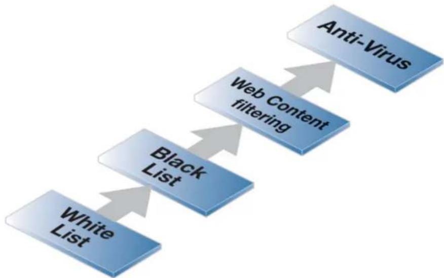
flowchart
graph TD
A["Anti-Virus"] --> B["Web Content filtering"]
B --> C["Black List"]
C --> D["White List"]
Figure 6.1. HTTP ALG Processing Order
Methods of Setting Up the HTTP ALG
Deploying the HTTP ALG can be done using one of the following methods:
• Using an IP Policy
Some HTTP ALG options can then be configured directly on an IP policy but most are configured by associating a Web Profile object with an IP policy. This is described further in Section 6.1.2.2, "HTTP ALG Setup With IP Policies".
Note that the IP policy must have its Service property assigned a service object which has its Protocol property set to HTTP.
Using an IP policy is the recommended way to deploy the HTTP ALG.
- Using an IP Rule
With this method, an HTTP ALG object is associated with a Service object that is then itself associated with an IP rule. All the ALG options are configured directly on the HTTP ALG object. This is described further in Section 6.1.2.3, "HTTP ALG Setup With IP Rules".
6.1.2.2. HTTP ALG Setup With IP Policies
The HTTP ALG options are configured on an IP Policy object with the following steps:
-
Create an IP Policy object with filtering properties that trigger on the target traffic.
-
The Service property of the IP policy must be set to a service object that has its Protocol property set to one the following values depending on the traffic targeted:
i. HTTP
ii. HTTPS
iii. HTTP and HTTPS
For HTTPS, the Service must include the port number 443 for HTTPS.
-
Set the values for any of the HTTP ALG settings which are directly configurable on the IP policy. These are discussed below.
-
Create a Web Profile object and associate this with the IP policy. This profile will allow many ALG features such as web content filtering and URL filtering to be configured.
-
Associate any other relevant objects with the IP policy. For example, a File Control Profile could be created and linked with the IP policy to impose restrictions on any files downloaded using HTTP.
HTTP ALG Options Directly Configurable on an IP Policy
The following options can be directly configured on an IP policy:
- Enable HTTP Inspection
The ALG will check that the HTTP traffic is valid HTTP. This includes checking that URLs do not include invalid UTF8 encoding. This is disabled by default.
- Allow Unknown Protocols
Non-HTTP compliant traffic will be allowed. This is disabled by default.
Web Profile Objects
When using an IP policy, much of the HTTP ALG functionality is configured in a Web Profile object which is then associated with an IP policy. The Web Profile has the following configurable properties:
- Name
A logical name for the object in the configuration.
- Allow Protocol Upgrade
This allows the HTTP connection to be upgraded to another protocol. For example, to HTTPS. The default is to allow this.
- Fail Mode
What action to take should there be an error in NetDefendOS processing. For example, the WCF databases might become unreachable. The default is Allow which means nothing is blocked.
- HTML Banner
This selects which HTML banner file to use for displaying to HTTP clients when access is denied.
- Web Content Filtering
This enables web content filtering. By default this is disabled. Web content filtering is discussed further in Section 6.2, "Web Content Filtering".
URL Filters
Specific URLs can be whitelisted (all checks are skipped) or blacklisted (the connection is dropped). This is done by adding one of more URL objects as children to a Web Profile object. URLs can be specified using wildcards and this is discussed further at the end of this section.
The URL Filter object has two key properties, the URL itself and the Action which can take one of the following values.
- Blacklist
Attempts to reach the URL are dropped.
- Whitelist
The URL is always accessible and no further ALG checks are performed.
It is important to note that whitelisting means that a URL cannot be blacklisted and it also cannot be dropped by web content filtering (if that is enabled, although it will be logged). Anti-Virus scanning, if it is enabled, is also not applied to HTTP traffic from a whitelisted URL.
- Redirect
The URL will automatically be redirected to a second URL which can be specified.
URL redirection has the same precedence as blacklisting. In other words, whitelisting takes priority and any redirection for the same URL is ignored. If the same URL is subject to both blacklisting and redirection because of an administrator mistake then one of them will be chosen at random as the action to perform.
URL redirection loops are discussed further later in this section. It is often advisable to whitelist the new URL so these cannot occur.
Whitelist and Blacklist Processing Precedence
Whitelisting always takes precedence over blacklisting. If, by mistake, the same URL is both blacklisted and whitelisted, the blacklisting action will be ignored because whitelisting is always processed first.
Precedences with Multiple URL Matches
When specifying URLs using wildcards, the possibility exists there can be more than one filter that matches a given URL. It should be noted that NetDefendOS does not choose the narrowest match. The action of the first match encountered will be taken and no further searching of the filters will occur.
Using Wildcards in URLs
Whitelisted and blacklisted URLs can make use of wildcarding to have a single entry be equivalent to a large number of possible URLs. The wildcard character "*" can be used to represent any sequence of characters.
For example, the entry *.example.com will block all pages whose URLs end with example.com.
If we want to now explicitly allow one particular page then this can be done with an entry in the whitelist of the form my_page.example.com and the blacklist will not prevent this page from being reachable since the whitelist has precedence.
Wildcard Examples
Below are some good and bad blacklisted example URLs that include wildcards:
| *.example.com/* | Good. This will block all hosts in the example.com domain and all web pages served by those hosts. This is the only correct form that can be used with HTTPS. |
| www.example.com/* | Good. This will block the www.example.com website and all web pages served by that site. |
| */*.gif | Good. This will block all files with .gif as the filename extension. |
| www.example.com | Not good. This will only block the first request to the website. Surfing to www.example.com/index.html, for example, will not be blocked. |
| *example.com/* | Not good. This will also cause www.myexample.com to be blocked since it blocks all sites ending with example.com. |
Only the Domain Level Can Be Targeted With HTTPS Traffic
Due to the encrypted nature of HTTPS, it is only possible to whitelist or blacklist at the domain level. For example, only the form *.example.com/* can be used for blacklisting or whitelisting with HTTPS. Using the form *.example.com is insufficient.
If *.example.com/server is specified for HTTPS traffic, this will not work and the matching URLs will not be caught.
Black/whitelisting Takes Precedence Over Web Content Filtering
Blacklisting and whitelisting occurs before web content filtering. This provides the possibility of manually making exceptions from the WCF process. In a scenario where goods have to be purchased from a particular online store, WCF might be set to prevent access to shopping sites
by blocking the "Shopping" category. However, whitelisting the online store's URL means that the URL is always allowed, taking precedence over dynamic content filtering.
Similarly, a static content filter that blacklists a URL means that URL will never reach dynamic content filtering.
URL Filtering Setup Using an IP Policy
When enabling URL filtering using an IP Policy object, a different set of objects is used. The setup steps are the following:
• Create a Web Profile object.
- Add one or more URL Filter objects as children of the Web Profile to define URLs that are whitelisted or blacklisted. Wildcarding can be used when specifying the URLs.
A third URL filtering option that is available only with the Web Profile object is to specify a redirect URL. In this case, NetDefendOS will cause a redirection of the triggering URL to the specified redirect URL. Whitelisting of the new URL may be needed and when to do this is explained later in this section.
- Create a new Service object for HTTP and/or HTTPS. A predefined object could be used for this purpose. This Service object must have its Protocol property set to be HTTP, HTTPS or HTTP and HTTPS. For HTTPS, the Service must include the port number 443 for HTTPS.
• Use the Service object with an IP policy that filters the relevant traffic.
- Set the Web Profile property of the IP Policy to the profile created earlier.
URL Redirection and Avoiding Redirection Loops
An important consideration when using URL redirection is the possible need to whitelist the new URL so that looping does not occur. This is because after URL substitution, the new URL is again checked against the URL filters. The following example will illustrate the problem.
Suppose a URL Filter object is created that specifies the triggering URL to be the wildcard character *. This means that any URL will trigger the filter. Suppose that the redirect option is chosen for this filter and the redirect URL is specified as www.example.com. When the substitution is performed, the new URL www.example.com will again be looked up against the filters and again will trigger in the same way, creating a loop. If www.example.com is first explicitly whitelisted in another then it can't trigger any filters and the loop is avoided.
Suppose instead that the URL Filter object triggers on the URL www.anotherexample.com and this is redirected to www.example.com. In this case, whitelisting of www.example.com would not be needed if that URL did not trigger another URL Filter object.

Important: HTTPS redirection will not work with IP policies
URL redirection cannot applied to HTTPS traffic via an IP Policy object. The administrator will get a configuration error when trying to activate this.
Example 6.1. URL Redirection with an IP Policy
This example illustrates how static content filtering is used with an IP policy to achieve URL redirection. The URL www.anotherexample.com is redirected to the URL www.example.com for a
pre-existing IP Policy object called my_web_profile.
Command-Line Interface
Create a new WebProfile object:
gw-world:/> add Policy WebProfile my_web_profile
Change the CLI context to be the profile:
gw-world:/> cc Policy WebProfile my_web_profile
Then add a filter as a child of the profile:
gw-world:/my_web_profile> add URLFilterPolicy_URL
URL=www.anotherexample.com
Action=Redirect
RedirectTo=http://www.example.com
Return to the default context:
gw-world:/my_web_profile> cc
gw-world:/>
Associate the profile with the relevant IP policy:
gw-world:/> set IPPolicy my_ip_policy
WebControl=Yes
Web_Policy=my_web_profile
Web Interface
Create a new WebProfile object:
- Go to: Policies > Web > Add > Web Profile
- Enter the name: my_web_profile
- Click OK
Add a URL filter:
- Select my_web_profile from the profile list
- Select URL Filter
- Select Add > URL
- Set Action to Redirect
- Set URL to www.anotherexample.com
- Set Redirect To to www.example.com
- Press OK
Associate the web profile with the relevant IP policy:
-
Go to: Policies > Main IP Rules
-
Select my_ip_policy
- Select Web Control
- Set Enable Web Control to On
- Set the Web Profile to my_web_profile
- Click OK
6.1.2.3. HTTP ALG Setup With IP Rules
This section looks at how the HTTP can be deployed using an HTTP ALG object directly with IP rules. This section is not applicable if IP policies are used to deploy the HTTP ALG.
Using an HTTP ALG Object with IP Rules
An HTTP ALG object is brought into use by first associating it with a service object and then associating that service object with an IP rule in the IP rule set. A number of predefined HTTP services could be used with the ALG. For example, the http service might be selected for this purpose. As long as the associated service is associated with an IP rule then the ALG will be applied to traffic targeted by that IP rule.
The Light Weight HTTP ALG Alternative
This section describes the standard HTTP ALG. In many situations the alternative Light Weight HTTP ALG (LW-HTTP ALG) can be a better choice since it requires less hardware resources and can provide higher traffic throughput. When using IP Policy objects the LW-HTTP ALG is used automatically when required. However, the stripping of static content and HTTPS processing are not available with the LW-HTTP ALG.
More information about the LW-HTTP ALG and the differences between the two ALGs can be found in Section 6.1.2.4, "Light Weight HTTP ALG".
HTTP ALG Object Features
An HTTP ALG object provides the following options:
• Active Content Handling
The optional blocking of any of the following is possible:
i. ActiveX objects can be stripped from web pages, including Flash.
ii. Java applets can be stripped from webpages.
iii. Javascript and Visual Basic Scripts can be stripped from webpages.
iv. Website cookies can be blocked.
Note that active content handling is not available when configuring the HTTP ALG with IP policies.

Caution: Consider the consequences of removing objects
Careful consideration should be given before enabling removal any object types from web content. Many websites use Javascript and other types of client-side code and in most cases, the code is non-malicious. Common examples of this is the scripting used to implement drop-down menus as well as hiding and showing elements on web pages.
Removing such legitimate code could, at best, cause the website to look distorted, at worst, cause it to not work in a browser at all. Active Content Handling should therefore only be used when the consequences are well understood.
- URL Verification
Some attacks can take the form of malformed URLs containing invalid encoding. Enabling this option will mean that the ALG checks for malformed URLs.
- File Control
A number of checks can be made on any files downloaded via HTTP. These are:
i. File Size - A file size limit can be specified for any single download (this option is only available for HTTP and SMTP ALG downloads).
ii. File Type Policy - It is possible to allow specific file types or to block specific file types.
iii. Allow/Block Selected Types
This option operates independently of the MIME verification option described above but is based on the predefined filetypes listed in Appendix C, Verified MIME filetypes. When enabled, the feature operates in either a Block Selected or an Allow Selected mode. These two modes function as follows:
i. Block Selected
The filetypes marked in the list will be dropped as downloads. To make sure that this is not circumvented by renaming a file, NetDefendOS looks at the file's contents (in a way similar to MIME checking) to confirm the file is what it claims to be.
If, for example, .exe files are blocked and a file with a filetype of .jpg (which is not blocked) is found to contain .exe data then it will be blocked. If blocking is selected but nothing in the list is marked, no blocking is done.
ii. Allow Selected
Only those filetypes marked will be allowed in downloads and other will be dropped. As with blocking, file contents are also examined to verify the file's contents. If, for example, .jpg files are allowed and a file with a filetype of .jpg is found to contain .exe data then the download will be dropped. If nothing is marked in this mode then no files can be downloaded.
Additional filetypes not included by default can be added to the Allow/Block list however these cannot be subject to content checking meaning that the file extension will be trusted as being correct for the contents of the file.
iv. Verify MIME Type
This option enables checking that the filetype of a file download agrees with the contents of the file (the term filetype here is also known as the filename extension).
All filetypes that are checked in this way by NetDefendOS are listed in Appendix C, Verified MIME filetypes. When enabled, any file download that fails MIME verification, in other words its filetype does not match its contents, is dropped by NetDefendOS on the assumption that it can be a security threat.
- Web Content Filtering
Access to specific URLs can be allowed or blocked according to policies for certain types of web content. Access to news sites might be allowed whereas access to gaming sites might be blocked. This feature is described in depth in Section 6.2, "Web Content Filtering".
- Anti-Virus Scanning
The contents of HTTP file downloads can be scanned for viruses. Suspect files can be dropped or just logged. This feature is common to a number of ALGs and is described fully in Section 6.4, "Anti-Virus Scanning".
- URL Filtering
The administrator can define the blacklisting and whitelisting of specific URLs. This is done by adding one or more HTTP ALG URL objects as children of a single parent HTTP ALG object.
i. URL Blacklisting
Specific URLs can be blacklisted so that they are not accessible. Wildcarding can be used when specifying URLs.
ii. URL Whitelisting
The opposite to blacklisting, this makes sure certain URLs are always allowed. Wildcarding can also be used for these URLs.
It is important to note that whitelisting a URL means that it cannot be blacklisted and it also cannot be dropped by web content filtering (if that is enabled, although it will be logged). Anti-Virus scanning, if it is enabled, is also not applied to HTTP traffic from a whitelisted URL.
Using wildcards when specifying URLs is discussed in Section 6.1.2.2, "HTTP ALG Setup With IP Policies".
Example 6.2. Stripping ActiveX and Java applets
This example shows how to configure a HTTP Application Layer Gateway to strip ActiveX and Java applets. The example will use the content_filtering ALG object and assumes one of the previous examples has been done.
Command-Line Interface
gw-world:/> set ALG ALG_HTTP content_filtering
RemoveActiveX=Yes
RemoveApplets=Yes
Web Interface
-
Go to: Objects > ALG
-
In the table, click on the HTTP ALG object, content_filtering
- Check the Strip ActiveX objects (including flash) control
- Check the Strip Java applets control
- Click OK
URL Filtering Setup Using an IP Rule
The following steps should be used for setting up URL filtering with an IP rule:
• Create an HTTP ALG object. For HTTPS traffic, set the Allowed Protocol property to be HTTPS.
- Add one or more HTTP ALG URL objects as children of the ALG to define the URLs that are whitelisted or blacklisted.
Note that redirection cannot be performed when using an IP rule and requires a Web Profile object associated with an IP Policy object, as described later in this section.
- Use this ALG in a Service object. The service object could be an existing or created object that allows HTTP and/or HTTPS traffic. For HTTPS, the service must include the port number 443.
- Associate the service object with an IP Rule object that has the appropriate filters set to trigger on the target traffic.
Example 6.3. URL Filtering Setup Using an IP Rule
This example shows the use of static content filtering where certain URLs are to be blacklisted and others whitelisted. This example also illustrates the use of wildcards to prevent the downloading of a specific filetype.
Assume that HTTP clients are to be prevented from downloading .exe files from any website using blacklisting with wildcards. However, .exe files downloaded from the www.example.com website are to be an exception to this rule and will be whitelisted.
Command-Line Interface
Begin by creating an HTTP ALG for HTTP traffic:
gw-world:/> add ALG ALG_HTTP my_content_filter
Change the CLI context to be the ALG:
gw-world:/> cc ALG ALG_HTTP my_content_filter
Then add an HTTP ALG URL as a child to blacklist a URL:
gw-world:/my_content_filter> add ALG_HTTP_URL
URL=*/*.exe
Action=Blacklist
Make an exception from the blacklist by adding a whitelisted URL:
gw-world:/my_content_filter> add ALG_HTTP_URL
URL=www.example.com/*.exe
Action=Whitelist
If no more filters are to added, return back to the default CLI context:
gw-world:/my_content_filter> cc
gw-world:/>
Web Interface
Start by adding an HTTP ALG in order to filter HTTP traffic:
- Go to: Objects > ALG > Add > HTTP ALG
- Enter a suitable name for the ALG, for example my_content_filter
- Click OK
Then create a HTTP ALG URL to set up a blacklist:
- Go to: Objects > ALG
- In the table, click on the recently created HTTP ALG to view its properties
- Click the HTTP URL tab
- Now click Add and select HTTP ALG URL from the menu
- Select Blacklist as the Action
- Enter */*.exe in the URL textbox
- Click OK
Finally, make an exception from the blacklist by creating a whitelist:
- Go to: Objects > ALG
- In the table, click on the recently created HTTP ALG to view its properties
- Click the HTTP URL tab
- Now click Add and select HTTP ALG URL from the menu
- Select Whitelist as the Action
- In the URL textbox, enter www.D-Link.com/*.exe
- Click OK
6.1.2.4. Light Weight HTTP ALG
The Light Weight HTTP ALG (LW-HTTP ALG) provides an alternative to the standard HTTP ALG when configuring the HTTP ALG using IP rules. If using IP policies, the LW-HTTP ALG will be deployed automatically when required so this section can be skipped. This section is only relevant if IP rules are being used for ALG deployment.
LW-HTTP ALG Advantages
The LW-HTTP ALG can provide the following key advantages over the standard HTTP ALG:
• Gives higher throughput performance than the standard HTTP ALG.
- Consumes much less memory than the standard HTTP ALG. This allows NetDefendOS to support a much greater number of concurrent connections.
- Can perform certain functions that the standard HTTP ALG cannot perform. These are listed next.
• Can be used with IPv6 based traffic.
Functions that Only the LW-HTTP ALG Can Perform
The following functions are only available in the LW-HTTP and do not exist in the standard HTTP ALG:
- HTTP Pipeline Support - A client can send multiple HTTP requests over a single TCP connection without waiting for the corresponding replies. This can result in a significant improvement in page loading times, particularly over network connections with high latency times. The standard HTTP ALG does not support pipelining.
- User Agent Filter Support - Specific browsers and/or browser versions can be allowed and all others blocked.
- Protocol Upgrade Support - The LW-HTTP ALG allows the protocol to be changed. For example, to the Web Sockets protocol.
Functions the LW-HTTP ALG Cannot Perform
The following functions cannot be provided by the LW-HTTP and can only be provided by the standard HTTP ALG:
• The LW-HTTP ALG does not support HTTPS traffic.
- The LW-HTTP ALG cannot modify a stream of HTTP data as it passes through the firewall. For this reason, the following static filtering cannot be performed:
i. Stripping active X objects.
ii. Stripping Javascript.
iii. Stripping Java applets.
iv. Blocking cookies.
- Anti-Virus scanning is only supported when the LW-HTTP ALG is used with an IP Policy object. It cannot be used for anti-virus scanning with an IP Rule object.
- File control is only supported when the LW-HTTP ALG is used with an IP Policy object. It cannot be used for file control with an IP Rule object.
User Agent Filtering
The User-Agent field of the HTTP protocol identifies the client software that is involved in the HTTP interaction. For many HTTP interactions this is a web browser. For example, the User-Agent field generated by the Firefox ^™ browser might look like the following:
Mozilla/5.0 (Windows NT 6.1; WOW64; rv:36.0) Gecko/20100101 Firefox/36.0
The network administrator may want to deny or allow certain web browsers or browser versions because they pose a security risk or because others are preferable.
The LW-HTTP ALG examine the User-Agent field as the traffic traverses the firewall and then only allow or deny access to agents which match a specified string. This is configured by attaching one or more User-Agent Filter objects as children to a parent LW-HTTP ALG object. Each filter object specifies a single string and the filter will trigger if the string matches a connection's User-Agent field. The behavior when it triggers is determined by the User-Agent Filter Mode property of the parent LW-HTTP ALG object and this can have one of two values:
- Deny Selected - Only the agents specified by the filter(s) will be denied. All other agents will be allowed. This is the default.
- Allow Selected - Only the agents specified by the filter(s) will be allowed. All other agents will be denied.
As can be seen from the agent example above for Firefox, the entire agent string can be long. It is therefore better when specifying the agent string in a filter to use wildcards. The following wildcards can be used:
• The asterisk "*" character represents any string.
• The question mark "?" character represents any single character.
For example, if only Firefox browser was to be allowed, a single filter could be specified with the following string:
*Firefox/*
When a User-Agent is blocked, NetDefendOS sends a predefined web page to the client's browser to alert them that this has happened. This page is not editable by the administrator at this time.

Note: Specifying no filters means all agents will be allowed
If no User Agent Filter objects are added to an LW-HTTP ALG object then all User-Agents will be allowed.
Example 6.4. Using the Light Weight HTTP ALG
This example shows how to set up a Light Weight HTTP (LW-HTTP) ALG for clients that are surfing the web using HTTP from a protected network to the Internet. It will be configured to allow only the Firefox and Chrome browsers (all other browsers will be denied). In addition, protocol upgrading will be allowed.
It is assumed that a single NAT IP rule is already configured which allows traffic from the internal network to the Internet. This rule is called int_to_ext_http
Command-Line Interface
First, create an LW-HTTP ALG object:
gw-world:/> add ALG ALG_LWHTTP my_lw_http_alg
AllowProtocolUpgrade=Yes
UserAgentFilterMode=AllowSelected
Change the CLI context to be the new ALG:
gw-world:/> cc ALG ALG_LWHTTP my_lw_http_alg
Add the User-Agent filter that will allow Firefox:
gw-world:/my_lw_http_alg> add ALG_HTTP_UA UserAgent=*Firefox/*
Add the User-Agent filter that will allow Chrome:
gw-world:/my_lw_http_alg> add ALG_HTTP_UA UserAgent=*Chrome/*
Return to the default CLI context:
gw-world:/my_lw_http_alg> cc
gw-world:/>
Now, create a service object and associate it with this new ALG:
gw-world:/> add Service ServiceTCPUDP my_http_service
Type=TCP
DestinationPorts=80
ALG=my_lw_http_alg
Finally, modify the NAT IP rule to use the new service.
gw-world:/> set IPRule int_to_ext_http Service=my_http_service
Web Interface
First, create an LW-HTTP ALG object:
-
Go to: Objects > ALG > Add > LW-HTTP ALG
-
Now enter:
-
Name: my_lw_http_alg
-
Allow Protocol Upgrade: Enable
• User-Agent Filter Mode: Allow Selected -
Click OK
Edit the LW-HTTP ALG just created:
- Select: my_lw_http_alg
-
Select User-Agent Filter
-
Select Add and enter the following to allow Firefox:
-
User-Agent: *Firefox/*
-
Click OK
-
Select Add and enter the following to allow Chrome:
-
User-Agent: *Chrome/*
-
Click OK
-
Click OK
Now, create a service object and associate it with this new ALG:
- Go to: Local Objects > Services > Add > TCP/UDP service
-
Enter the following:
-
Name: my_http_service
- Type: TCP
• Destination Port: 80443 - ALG: my_lw_http_alg
Finally, modify the NAT IP rule to use the new service:
- Go to: Policies > Firewalling > Main IP Rules
- Select the IP rule called int_to_ext_http
- Go to: Service
- Select my_http_service from the Service list
- Click OK
6.1.3. FTP ALG
Overview
File Transfer Protocol (FTP) is a TCP/IP-based protocol for exchanging files between a client and a server. The client initiates the connection by connecting to the FTP server. Normally the client needs to authenticate itself by providing a predefined login and password. After granting access, the server will provide the client with a file/directory listing from which it can download/upload files (depending on access rights). The FTP ALG is used to manage FTP connections through the D-Link firewall.
FTP Connections
FTP uses two communication channels, one for control commands and one for the actual files being transferred. When an FTP session is opened, the FTP client establishes a TCP connection (the control channel) to port 21 (by default) on the FTP server. What happens after this point depends on the FTP mode being used.
FTP Connection Modes
FTP operates in two modes: active and passive. These determine the role of the server when opening data channels between client and server.
- Active Mode
In active mode, the FTP client sends a command to the FTP server indicating what IP address and port the server should connect to. The FTP server establishes the data channel back to the FTP client using the received address information.
- Passive Mode
In passive mode, the data channel is opened by the FTP client to the FTP server, just like the command channel. This is the often recommended default mode for FTP clients though some advice may recommend the opposite.
A Discussion of FTP Security Issues
Both active and passive modes of FTP operation can present problems. Consider a scenario where an FTP client on the internal network connects through the firewall to an FTP server on the Internet. The IP rule is then configured to allow network traffic from the FTP client to port 21 on the FTP server.
When active mode is used, NetDefendOS does not know that the FTP server will establish a new connection back to the FTP client. Therefore, the incoming connection for the data channel will be dropped. As the port number used for the data channel is dynamic, the only way to solve this is to allow traffic from all ports on the FTP server to all ports on the FTP client. Obviously, this is not a good solution.
When passive mode is used, the firewall does not need to allow connections from the FTP server. On the other hand, NetDefendOS still does not know what port the FTP client will try to use for the data channel. This means that it has to allow traffic from all ports on the FTP client to all ports on the FTP server. Although this is not as insecure as in the active mode case, it still presents a potential security threat. Furthermore, not all FTP clients are capable of using passive mode.
The NetDefendOS ALG Solution
The NetDefendOS FTP ALG deals with these issues by fully reassembling the TCP stream of the FTP command channel and examining its contents. By doing this, the NetDefendOS knows what port to open for the data channel. Furthermore, the FTP ALG also provides functionality to filter out certain control commands and provide buffer overrun protection.
Hybrid Mode
An important feature of the NetDefendOS FTP ALG is its automatic ability to perform on-the-fly conversion between active and passive mode so that FTP connection modes can be combined. Passive mode can be used on one side of the firewall while active mode can be used on the
other. This type of FTP ALG usage is sometimes referred to as hybrid mode.
The advantage of hybrid mode can be summarized as follows:
- The FTP client can be configured to use passive mode, which is the recommended mode for clients.
- The FTP server can be configured to use active mode, which is the safer mode for servers.
- When an FTP session is established, the firewall will automatically and transparently receive the passive data channel from the FTP client and the active data channel from the server, and correctly tie them together.
This implementation results in both the FTP client and the FTP server working in their most secure mode. The conversion also works the other way around, that is, with the FTP client using active mode and the FTP server using passive mode. The illustration below shows the typical hybrid mode scenario.
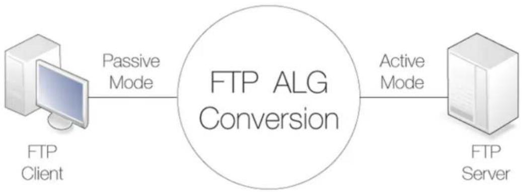
flowchart
graph LR
A["FTP Client"] -->|Passive Mode| B["FTP ALG Conversion"]
B -->|Active Mode| C["FTP Server"]
Figure 6.2. FTP ALG Hybrid Mode

Note: Hybrid conversion is automatic
Hybrid mode does not need to be enabled. The conversion between modes occurs automatically within the FTP ALG.
Connection Restriction Options
The FTP ALG has two options to restrict which type of mode the FTP client and the FTP server can use:
- Allow the client to use active mode.
If this is enabled, FTP clients are allowed to use both passive and active transfer modes. With this option disabled, the client is limited to using passive mode. If the FTP server requires active mode, the NetDefendOS FTP ALG will handle the conversion automatically to active mode.
A range of client data ports is specified with this option. The server will be allowed to connect to any of these if the client is using active mode. The default range is 1024-65535.
- Allow the server to use passive mode.
If this option is enabled, the FTP server is allowed to use both passive and active transfer modes. With the option disabled, the server will never receive passive mode data channels. NetDefendOS will handle the conversion automatically if clients use passive mode.
A range of server data ports is specified with this option. The client will be allowed to connect to any of these if the server is using passive mode. The default range is 1024-65535.
These options can determine if hybrid mode is required to complete the connection. For example, if the client connects with passive mode but this is not allowed to the server then hybrid mode is automatically used and the FTP ALG performs the conversion between the two modes.
Predefined FTP ALGs and Services Before NetDefendOS Version 11.01
In older versions of NetDefendOS, four predefined FTP ALG and Service objects were provided, each with a different combination of client/server mode restrictions. These ALG and Service objects had the following names:
- ftp-inbound - Clients can use any mode but servers cannot use passive mode.
- ftp-outbound - Clients cannot use active mode but servers can use any mode.
- ftp-passthrough - Both the client and the server can use any mode.
- ftp-internal - The client cannot use active mode and the server cannot use passive mode.
Beginning with NetDefendOS version 11.01, these individual services are removed from a new NetDefendOS installation. However, they remain in configurations that upgrade to 11.01 or later. A new installation can recreate them manually but the recommended option is to use the predefined ftp service with an IP Policy object, in which case all the options previously available on the ALG are now available directly on the policy.
FTP ALG Command Restrictions
The FTP protocol consists of a set of standard commands that are sent between server and client. If the NetDefendOS FTP ALG sees a command it does not recognize then the command is blocked. This blocking must be explicitly lifted and the options for lifting blocking are:
- Allow unknown FTP commands. These are commands the ALG does not consider part of the standard set.
- Allow the SITE EXEC command to be sent to an FTP server by a client.
- Allow the RESUME command even if content scanning terminated the connection.

Note: Some FTP commands are never allowed
Some commands, such as encryption instructions, are never allowed. Encryption would mean that the FTP command channel could not be examined by the ALG and the dynamic data channels could not be opened.
The following is a list of commands that are never allowed by the ALG:
• CLNT
• MLST
• MLSD
• FILT
• EPRT
• EPSV
• AUTH
• ADAT
• PBSZ
• PROT
• CCC
• MIC
• CONF
• ENC
Control Channel Restrictions
The FTP ALG also allows restrictions to be placed on the FTP control channel which can improve the security of FTP connections. These are:
• Maximum line length in control channel
Creating very large control channel commands can be used as a form of attack against a server by causing buffer overruns This restriction combats this threat. The default value is 256
If very long file or directory names on the server are used then this limit may need to be raised. The shorter the limit, the better the security.
• Maximum number of commands per second
To prevent automated attacks against FTP server, restricting the frequency of commands can be useful. The default limit is 20 commands per second.
- Allow 8-bit strings in control channel
The option determines if 8-bit characters are allowed in the control channel. Allowing 8-bit characters enables support for filenames containing international characters. For example, accented or umlauted characters.
Filetype Checking of FTP Transfers
To configure filetype checking with an IP Policy, a File Control Profile must be defined and then associated with the IP policy that allows the FTP transfer. This is described further in Section 6.5, "File Control".
Anti-Virus Scanning of FTP Transfers
The NetDefendOS anti-virus subsystem can be enabled to scan all FTP file downloads for malicious code. Suspect files can be dropped or just logged. With an IP policy, anti-virus scanning is enabled by associating an Anti-Virus Profile with the IP policy that allows the FTP transfer. This is described further in Section 6.4, "Anti-Virus Scanning".
Setting Up FTP Servers with Passive Mode
An important point about FTP server setup needs to be made if the FTP ALG is being used along with passive mode.
Usually, the FTP server will be protected behind the D-Link firewall and NetDefendOS will SAT-Allow connections to it from external clients that are connecting across the Internet. If FTP Passive mode is allowed and a client connects with this mode then the FTP server must return an IP address and port to the client on which it can set up the data transfer connection.
This IP address is normally manually specified by the administrator in the FTP server software and the natural choice is to specify the external IP address of the interface on the firewall that connects to the Internet. This is, however, wrong if the FTP ALG is being used.
Instead, the local, internal IP address of the FTP server should be specified when setting up the FTP server.
FTP ALG with ZoneDefense
ZoneDefense is a feature that allows NetDefendOS to block hosts and networks by sending management commands to certain types of external network switches. Used together with the FTP ALG, ZoneDefense can be configured to protect a network from the spread of malware such as viruses. This is relevant in two scenarios:
A. Infected clients that need to be blocked.
B. Infected servers that need to be blocked.
These two scenarios will now be discussed in detail.
A. Blocking Infected Clients
The administrator configures the network range to include the local hosts of the network. If a local client tries to upload a virus infected file to an FTP server, NetDefendOS notices that the client belongs to the local network and will therefore upload blocking instructions to the local switches. The host will be blocked from accessing the local network and can no longer do any harm.
However, if a client downloads an infected file from a remote FTP server on the Internet, the server will not be blocked by ZoneDefense since it is outside of the configured network range. The virus is, however, still blocked by the firewall.
B. Blocking Infected Servers
Depending on the company policy, an administrator might want to take an infected FTP server off-line to prevent local hosts and servers from being infected. In this scenario, the administrator configures the address of the server to be within the range of the network to block. When a client downloads an infected file, the server is isolated from the network.
The steps for setting up ZoneDefense with the FTP ALG are the following:
- Configure the ZoneDefense switches to be used with ZoneDefense in the ZoneDefense section of the Web Interface.
- Set up the FTP ALG to use Anti-Virus scanning in enabled mode.
- Choose the ZoneDefense network in the Anti-Virus configuration of the ALG that is to be affected by ZoneDefense when a virus is detected.
For more information about this topic refer to Section 7.9, "ZoneDefense".
Methods of Setting Up the FTP ALG
Deploying the FTP ALG can be done using one of the following methods:
- Using IP Policies
Using an IP Policy object is the recommended setup method. It is easiest and provides additional options that are not available with IP rules. The FTP ALG options are configured directly by setting properties of the IP policy. Note that to configure FTP options with an IP policy, the policy's Service property must be assigned a service object which has its Protocol property set to FTP.
- Using IP Rules
When using IP Rule objects, an FTP ALG object is associated with a Service object that is then associated with an IP rule.
This setup method can be useful for compatibility with older NetDefendOS versions but does not provide any advantages over using an IP policy.
FTP ALG Setup Using IP Policies
Deploying the FTP ALG using IP policies requires the following steps:
- Create a new service object for FTP and set its Protocol property to be FTP. Alternatively, the predefined FTP service object called ftp could be used instead provided it has its Protocol property set to FTP.
- Create a new IP Policy object that triggers on the targeted traffic and set its Service property to be the service object from the previous step. These will make all the FTP ALG options available on the IP policy and these should be set appropriately.
- Associate any other desired features with the IP policy. For example, associate a File Control Policy object for imposing file restrictions and/or a Anti-Virus Profile to perform anti-virus scanning on files.
The two examples that follow show how the FTP ALG is set up using IP policies for either FTP client or FTP server protection.
Example 6.5. FTP ALG Setup Using IP Policies to Protect an FTP Server
This example shows how to protect the server using the FTP ALG. An FTP Server on a DMZ is connected to a D-Link firewall and has a private IPv4 address, as illustrated below.
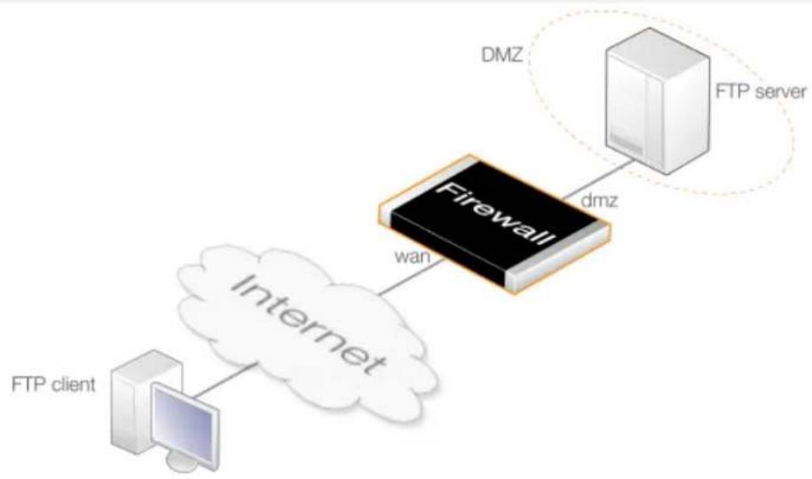
flowchart
graph TD
A["FTP client"] --> B["Internet"]
B --> C["Firewall"]
C --> D["DMZ"]
D --> E["FTP server"]
style C fill:#000,stroke:#fff,color:#fff
style D fill:#f9f,stroke:#000,color:#fff
style E fill:#ccf,stroke:#000,color:#fff
The FTP ALG restrictions will be the following:
- Enable the FTP ALG option Allow active mode for client so FTP clients can use both active and passive modes.
- Disable the FTP ALG option Allow passive mode for server. This is more secure for the FTP server as it will never receive passive mode data. The FTP ALG will handle all conversion if a client connects using passive mode.
Assume that the private IPv4 address of the FTP server is already defined in the address book with the name ftp-internal.
Command-Line Interface
A. Define a custom FTP service:
gw-world:/> add Service ServiceTCPUDP ftp-inbound-service DestinationPorts=21 Type=TCP Protocol=FTP
B. Define a SAT policy translating connections to the public IP on port 21 to the server:
gw-world:/> add IPPolicy Name=sat-ftp-inbound
SourceInterface=any
SourceNetwork=all-nets
DestinationInterface=core
DestinationNetwork=wan_ip
Service=ftp-inbound-service
Action=Allow
SourceAddressTranslation=None
DestinationAddressTranslation=SAT
DestinationAddressAction=SingleIP
DestNewIP=ftp-internal
FTPControl=Yes
FTPAllowServerPassive=Yes
FTPAllowClientActive=Yes
C. Traffic from the internal interface needs to be NATed through the public IPv4 address:
gw-world:/> add IPPolicy Name=nat-ftp SourceInterface=dmz
SourceNetwork=dmznet
DestinationInterface=core
DestinationNetwork=wan_ip
Service=ftp-inbound-service
Action=Allow
SourceAddressTranslation=NAT
NATSourceAddressAction=OutgoingInterfaceIP
FTPControl=Yes
FTPAllowServerPassive=Yes
FTPAllowClientActive=Yes
Web Interface
A. Define a custom FTP service:
- Go to: Objects > Services > Add > TCP/UDP Service
- Enter the following:
• Name: ftp-inbound-service
- Type: TCP
- Destination: 21
- Protocol: FTP
- Click OK
B. Define a SAT policy translating connections to the public IP on port 21 to the server:
- Go to: Policies > Firewalling > Main IP Rules > Add > IP Policy
-
Now enter:
-
Name: sat-ftp-inbound
• Action: SAT -
Under Filter enter:
-
Source Interface: any
- Destination Interface: core
- Source Network: all-nets
-
Destination Network: wan_ip
• Service: ftp-inbound-service -
Under Source Translation enter:
- Address Translation: None
-
Under Destination Translation enter:
-
Address Translation: SAT
• Address Action: Single IP
• New IP Address: ftp-internal
6. Under FTP enter:
• Use custom FTP settings: ON
- Allow active mode for client: Enabled
- Allow passive mode for server: Enabled
7. Click OK
C. Traffic from the internal interface needs to be NATed through the public IPv4 address:
-
Go to: Policies > Firewalling > Main IP Rules > Add > IP Policy
-
Now enter:
-
Name: nat-ftp
• Action: NAT -
Under Filter enter:
-
Source Interface: dmz
- Destination Interface: core
• Source Network: dmznet -
Destination Network: wan_ip
• Service: ftp-inbound-service -
Under Source Translation enter:
-
Address Translation: NAT
• Address Action: Outgoing Interface IP -
Under FTP enter:
• Use custom FTP settings: ON
- Allow active mode for client: Enabled
- Allow passive mode for server: Enabled
6. Click OK
Example 6.6. FTP ALG Setup Using an IP Policy to Protect FTP Clients
This example shows how to protect FTP clients behind a firewall that are connecting to remote FTP servers on the Internet. The diagram below illustrates this scenario.
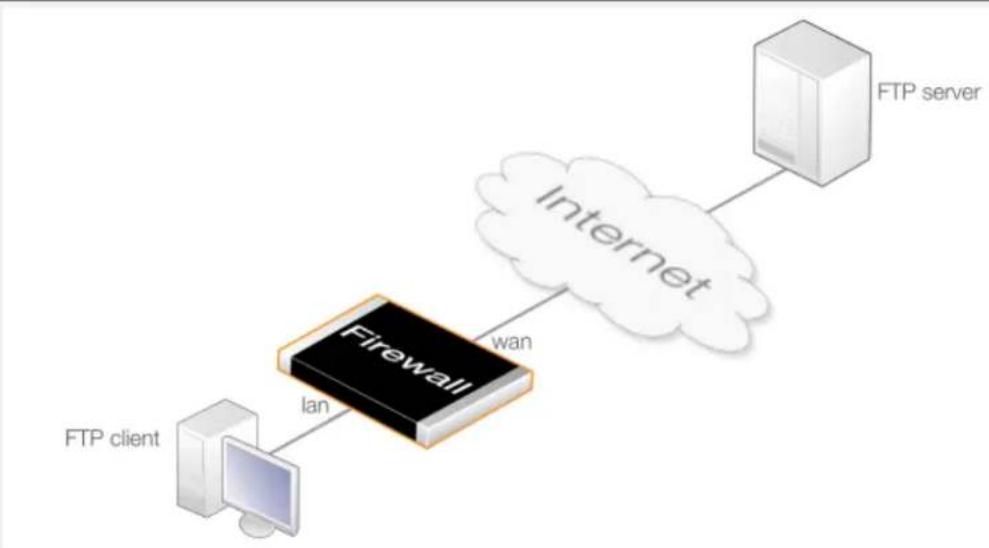
flowchart
graph LR
A["FTP client"] -->|lan| B["Firewall"]
B -->|wan| C["Internet"]
C --> D["FTP server"]
The FTP ALG will use the following options:
- The FTP ALG option Allow active mode for client will be disabled so clients can only use passive mode. This is much safer for clients.
- The FTP ALG option Allow passive mode for server will be enabled. This allows internal clients to connect to FTP servers that support active and passive mode across the Internet.
Command-Line Interface
A. Define the FTP Service:
gw-world:/> add Service ServiceTCPUDP ftp-outbound-service DestinationPorts=21
Type=TCP
Protocol=FTP
B. Create IP Policies:
IP rules need to be created to allow the FTP traffic to pass and these are different depending on if private or public IPv4 addresses are being used.
i. Using Public IPs:
If using public IPs throughout, make sure there are no rule set entries disallowing or allowing the same kind of ports/traffic placed before this entry
gw-world:/> add IPPolicy Name=allow-ftp-outbound
SourceInterface=lan
SourceNetwork=lannet
DestinationInterface=wan
DestinationNetwork=all-nets
Service=ftp-outbound-service
Action=Allow
SourceAddressTranslation=None
FTPControl=Yes
FTPAllowServerPassive=Yes
FTPAllowClientActive=No
ii. Using Private IPs:
If the firewall is using private IPs for protected clients and a single external public IP for the Internet connection, the following NAT IP policy needs to be added instead of the previous policy in i above:
gw-world:/> add IPPolicy Name=nat-ftp-outbound
SourceInterface=lan
SourceNetwork=lannet
DestinationInterface=wan
DestinationNetwork=all-nets
Service=ftp-outbound-service
Action=Allow
SourceAddressTranslation=NAT
NATSourceAddressAction=OutgoingInterfaceIP
FTPControl=Yes
FTPAllowServerPassive=Yes
FTPAllowClientActive=No
Web Interface
A. Define the FTP Service:
- Go to: Objects > Services > Add > TCP/UDP Service
- Now enter:
• Name: ftp-outbound-service
- Type: TCP
- Destination: 21
- Protocol: FTP
- Click OK
B. Create IP Policies:
IP rules need to be created to allow the FTP traffic to pass and these are different depending on if private or public IPv4 addresses are being used.
i. Using Public IPs:
If using public IPs throughout, make sure there are no rule set entries disallowing or allowing the same kind of ports/traffic placed before this entry.
- Go to: Policies > Firewalling > Main IP Rules > Add > IP Policy
-
Now enter:
-
Name: allow-ftp-outbound
-
Action: Allow
-
Under Filter enter:
-
Source Interface: Ian
- Destination Interface: wan
-
Source Network: Iannet
-
Destination Network: all-nets
• Service: ftp-outbound-service -
Under Source Translation enter:
- Address Translation: None
- Under FTP enter:
• Use custom FTP settings: ON
- Allow active mode for client: Disabled
- Allow passive mode for server: Enabled
- Click OK
ii. Using Private IPs:
If the firewall is using private IPs for protected clients and a single external public IP for the Internet connection, the following NAT IP policy needs to be added instead of the previous policy in i above:
- Go to: Policies > Firewalling > Main IP Rules > Add > IP Policy
-
Now enter:
-
Name: nat-ftp-outbound
• Action: NAT -
Under Filter enter:
-
Source Interface: Ian
- Destination Interface: wan
- Source Network: Iannet
-
Destination Network: all-nets
• Service: ftp-outbound-service -
Under Source Translation enter:
-
Address Translation: NAT
• Address Action: Outgoing Interface IP -
Under FTP enter:
• Use custom FTP settings: ON
- Allow active mode for client: Disabled
- Allow passive mode for server: Enabled
- Click OK
FTP ALG Setup Using IP Rules
An alternative to uses IP policies for FTP ALG setup is to use IP rules. This requires the following steps:
- Create a new FTP ALG object with the desired options configured.
- Create a new custom Service object for FTP and set its ALG property to the object created in the previous step.
- Create an IP Rule object that that uses the Service from the previous step. Multiple rules will be needed for SAT address translation.
The two examples that follow show how the FTP ALG is set up using IP rules for either FTP client or FTP server protection and replicate the scenarios of the previous examples that used IP policies.
Example 6.7. FTP ALG Setup Using IP Rules to Protect an FTP Server
This example repeats Example 6.5, "FTP ALG Setup Using IP Policies to Protect an FTP Server" but uses an IP Rule instead of an IP Policy.
Command-Line Interface
A. Define the ALG:
gw-world:/> add ALG ALG_FTP ftp-inbound
AllowClientActive=Yes
AllowServerPassive=Yes
B. Define the Service:
gw-world:/> add Service ServiceTCPUDP ftp-inbound-service DestinationPorts=21 Type=TCP ALG=ftp-inbound
C. Define a SAT rule allowing connections to the public IP on port 21 and forwarded to the FTP server:
gw-world:/> add IPRule Action=SAT
SourceInterface=any
SourceNetwork=all-nets
DestinationInterface=core
DestinationNetwork=wan_ip
Service=ftp-inbound-service
SATTranslate=DestinationIP
SATTranslateToIP=ftp-internal
Name=SAT-ftp-inbound
D. Traffic from an internal interface needs to be NATed through the public IPv4 address:
gw-world:/> add IPRule Action=NAT
SourceInterface=dmz
SourceNetwork=dmznet
DestinationInterface=core
DestinationNetwork=wan_ip
Service=ftp-inbound-service
NATAction=UseInterfaceAddress
Name=NAT-ftp
E. Allow incoming connections (SAT requires an associated Allow rule):
gw-world:/> add IPRule Action=Allow
SourceInterface=any
SourceNetwork=all-nets
DestinationInterface=core
DestinationNetwork=wan_ip
Service=ftp-inbound-service
Name=Allow-ftp
Web Interface
A. Define the ALG:
- Go to: Objects > ALG > Add > FTP ALG
- Enter Name: ftp-inbound
- Check Allow client to use active mode
- Uncheck Allow server to use passive mode
- Click OK
B. Define the Service:
-
Go to: Objects > Services > Add > TCP/UDP Service
-
Enter the following:
• Name: ftp-inbound-service
• Type: select TCP from the list
• Destination: 21 (the port the FTP server resides on)
• ALG: select ftp-inbound created above
3. Click OK
C. Define a SAT rule allowing connections to the public IP on port 21 and forwarded to the FTP server:
- Go to: Policies > Firewalling > Main IP Rules > Add > IP Rule
- Now enter:
-
Name: SAT-ftp-inbound
• Action: SAT
• Service: ftp-inbound-service -
For Address Filter enter:
- Source Interface: any
- Destination Interface: core
- Source Network: all-nets
-
Destination Network: wan_ip (assuming the external interface has been defined as this)
-
For SAT check Translate the Destination IP Address
-
Enter To: New IP Address: ftp-internal
-
New Port: 21
-
Click OK
D. Traffic from an internal interface needs to be NATed through the public IPv4 address:
-
Go to: Policies > Firewalling > Main IP Rules > Add > IP Rule
-
Now enter:
-
Name: NAT-ftp
• Action: NAT
• Service: ftp-inbound-service -
For Address Filter enter:
-
Source Interface: dmz
- Destination Interface: core
- Source Network: dmznet
-
Destination Network: wan_ip
-
For NAT check Use Interface Address
-
Click OK
E. Allow incoming connections (SAT requires an associated Allow rule):
-
Go to: Policies > Firewalling > Main IP Rules > Add > IP Rule
-
Now enter:
-
Name: Allow-ftp
-
Action: Allow
• Service: ftp-inbound-service -
For Address Filter enter:
-
Source Interface: any
-
Destination Interface: core
-
Source Network: all-nets
-
Destination Network: wan_ip
-
Click OK
Example 6.8. FTP ALG Setup Using IP Rules to Protect FTP Clients
This example repeats Example 6.5, "FTP ALG Setup Using IP Policies to Protect an FTP Server" but uses an IP Rule instead of an IP Policy.
Command-Line Interface
A. Define the ALG:
gw-world:/> add ALG ALG_FTP ftp-outbound
AllowClientActive=No
AllowServerPassive=Yes
B. Define the FTP Service:
gw-world:/> add Service ServiceTCPUDP ftp-outbound-service DestinationPorts=21 Type=TCP ALG=ftp-outbound
C. Create IP Rules:
IP rules need to be created to allow the FTP traffic to pass and these are different depending on if private or public IPv4 addresses are being used.
i. Using Public IPs:
If using public IPs, make sure there are no rules disallowing or allowing the same kind of ports/traffic placed before this rule.
gw-world:/> add IPRule Action=Allow
SourceInterface=lan
SourceNetwork=lannet
DestinationInterface=wan
DestinationNetwork=all-nets
Service=ftp-outbound-service
Name=Allow-ftp-outbound
ii. Using Private IPs:
If the firewall is using private IPs with a single external public IP, the following NAT rule needs to be added instead of the rule above:
gw-world:/> add IPRule Action=NAT
SourceInterface=lan
SourceNetwork=lannet
DestinationInterface=wan
DestinationNetwork=all-nets
Service=ftp-outbound-service NATAction=UseInterfaceAddress Name=NAT-ftp-outbound
Web Interface
A. Create the FTP ALG:
- Go to: Objects > ALG > Add > FTP ALG
- Enter Name: ftp-outbound
- Uncheck Allow client to use active mode
- Check Allow server to use passive mode
- Click OK
B. Create the Service:
- Go to: Objects > Services > Add > TCP/UDP Service
- Now enter:
• Name: ftp-outbound-service
• Type: select TCP from the dropdown list
• Destination: 21 (the port the ftp server resides on)
• ALG: ftp-outbound
3. Click OK
C. Create IP Rules:
IP rules need to be created to allow the FTP traffic to pass and these are different depending on if private or public IPv4 addresses are being used.
i. Using Public IPs:
If using public IPs, make sure there are no rules disallowing or allowing the same kind of ports/traffic placed before this rule.
- Go to: Policies > Firewalling > Main IP Rules > Add > IP Rule
- Now enter:
• Name: Allow-ftp-outbound
• Action: Allow
• Service: ftp-outbound-service
-
For Address Filter enter:
-
Source Interface: Ian
-
Destination Interface: wan
-
Source Network: Iannet
- Destination Network: all-nets
4. Click OK
ii. Using Private IPs:
If the firewall is using private IPs with a single external public IP, the following NAT rule needs to be added instead of the rule above:
- Go to: Policies > Firewalling > Main IP Rules > Add > IP Rule
- Now enter:
• Name: NAT-ftp-outbound
• Action: NAT
• Service: ftp-outbound-service
-
For Address Filter enter:
-
Source Interface: Ian
- Destination Interface: wan
- Source Network: Iannet
-
Destination Network: all-nets
-
Check Use Interface Address
-
Click OK
6.1.4. TFTP ALG
Overview
Trivial File Transfer Protocol (TFTP) is a much simpler version of FTP with more limited capabilities. Its purpose is to allow a client to upload files to or download files from a host system. TFTP data transport is based on the UDP protocol and therefore it supplies its own transport and session control protocols which are layered onto UDP.
TFTP is widely used in enterprise environments for updating software and backing up configurations on network devices. TFTP is recognized as being an inherently insecure protocol and its usage is often confined to internal networks. The NetDefendOS ALG provides an extra layer of security to TFTP in being able to put restrictions on its use.
Methods of Setting Up the TFTP ALG
Deploying the TFTP ALG can be done using one of the following methods:
- Using IP Policies
Using an IP Policy object is the recommended setup method. It is easiest and provides additional options that are not available with IP rules. The TFTP ALG options are configured directly by setting properties of the IP policy. Note that to configure TFTP options with an IP policy, the policy's Service property must be assigned a service object which has its Protocol property set to TFTP.
- Using IP Rules
When using IP Rule objects, an TFTP ALG object is associated with a Service object that is then associated with an IP rule.
This setup method can be useful for compatibility with older NetDefendOS versions but does not provide any advantages over using an IP policy. It will not be discussed further in this section.
TFTP ALG Setup Using an IP Policy
This section will discuss setting up the TFTP ALG using an IP Policy object. This is done with the following steps:
- Create a new service object which is a copy of the predefined tftp service and set its Protocol property to TFTP. Alternatively, set the Protocol property of the predefined service called tftp to the value TFTP and use that.
- Create a new IP Policy object that triggers on the targeted traffic and set its Service property to be the service object from the previous step. These will make the TFTP options available on the IP policy.
- Make any adjustments to how the TFTP ALG behaves by changing the relevant properties of the IP Policy. The available options are discussed next.
TFTP ALG Options
The following options can be set on an IP Policy object once the Service for the TFTP protocol is associated with it:
- Use custom TFTP settings
Set this to ON to activate the TFTP ALG.
- Allow read/write
The ALG can be set up to allow both read and write operations or just read or just write.
- Remove options
Specifies if options should be removed from requests. The default is do not remove.
- Allow unknown options
If this option is not enabled then any option in a request other than the blocksize, the timeout period and the file transfer size is blocked. The setting is disabled by default.
Specific TFTP Request Options
As long as the Remove Options property is set to false (options are not removed) then the following request option settings can also be set:
- Max blocksize
The maximum blocksize allowed can be specified. The allowed range is 0 to 65,464 bytes. The default value is 65,464 bytes.
- Max file transfer size
The maximum size of a file transfer can be restricted. By default this is the maximum possible allowed which 999,999 Kbytes.
- Block directory traversal
This option can disallow directory traversal through the use of filenames containing consecutive periods ("..").
Request Repetition
The NetDefendOS TFTP ALG blocks the repetition of an TFTP request coming from the same source IP address and port within a fixed period of time. The reason for this is that some TFTP clients might issue requests from the same source port without allowing an appropriate timeout period the reply.
Example 6.9. TFTP ALG Setup Using an IP Policy
In this example, read-only TFTP connections are allowed from the Internet to a web server located in a DMZ. The D-Link firewall is connected to the Internet via the wan interface with address object wan_ip as its IP address. The web server has the private IPv4 address 198.168.0.1 and so connections arriving at the wan interface will be subject to SAT translation.
The predefined NetDefendOS service called tftp will be used but it will need to have its Protocol property set first.
Command-Line Interface
Set the Protocol property of the tftp service :
gw-world:/> set Service ServiceTCPUDP tftp Protocol=TFTP
Create a SAT IP Policy for TFTP:
gw-world:/> add IPPolicy Name=SAT_TFTP_To_DMZ
SourceInterface=wan
SourceNetwork=all-nets
DestinationInterface=core
DestinationNetwork=wan_ip
Service=tftp
Action=Allow
SourceAddressTranslation=None
DestinationAddressTranslation=SAT
DestinationAddressAction=SingleIP
DestNewIP=192.168.0.1
TFTControl=Yes
TFTPAllowedCommands=Read
Web Interface
Set the Protocol property of the tftp service :
- Go to: Objects > Services
- Select tftp
- For Protocol select TFTP
- Click OK
Create a SAT IP policy for TFTP:
- Go to: Policies > Firewalling > Main IP Rules > Add > IP Policy
-
Now enter:
-
Name: SAT_TFTP_To_DMZ
-
Action: Allow
-
Under Filter enter:
-
Source Interface: wan
- Source Network: all-nets
- Destination Interface: core
-
Destination Network: wan_ip
• Service: tftp -
Under Source Translation enter:
- Address Translation: None
-
Under Destination Translation enter:
-
Address Translation: SAT
• Address Action: Single IP -
New IP Address: 10.0.0.5
-
Under TFTP enter:
• Use custom TFTP settings: ON
- Allow read: Enabled
- Click OK
6.1.5. SMTP ALG
Overview
Simple Mail Transfer Protocol (SMTP) is a text based protocol used for transferring email between mail servers over the Internet. Typically, a local mail server will be located on a DMZ so that mail sent by remote mail servers will traverse the D-Link firewall to reach the local server.
Local clients behind the firewall will then use email client software to retrieve email from the server and to send mail to the server for forwarding out to other mail servers on the Internet. Various protocols may be used for communication between clients and a mail server. Microsoft ActiveSync ^™ is a common choice. Retrieval may also be done with the POP3 or IMAP protocol but sending mail to the server may be done using SMTP. These interactions are illustrated in the diagram below.
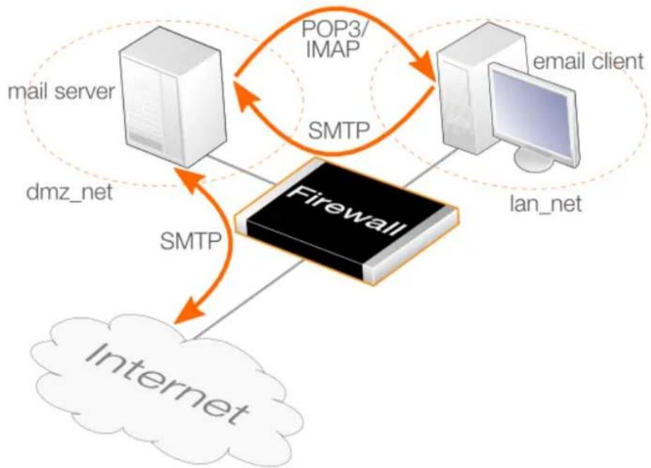
flowchart
graph TD
A["mail server"] -->|SMTP| B["Firewall"]
C["email client"] -->|SMTP| B
D["dmz_net"] -->|SMTP| B
B --> E["Internet"]
style A fill:#f9f,stroke:#333
style C fill:#f9f,stroke:#333
style D fill:#f9f,stroke:#333
style B fill:#ccf,stroke:#333
style E fill:#cfc,stroke:#333
Figure 6.3. SMTP ALG Usage
The SMTP ALG can be used to process both SMTP traffic between mail servers as well as from clients to servers. A typical mail sending sequence would be the following:
- A local user sends an email to a mail server. This might be sent using SMTP or Microsoft Activesync ^™ or some other protocol.
- The local mail server performs a DNS lookup of the destination domain name to determine the IP address of the remote mail server to forward the mail to.
- The email is forwarded to the remote server using SMTP.
- The remote user retrieves the email from the remote mail server using POP3 or IMAP or Activesync or some other protocol.
The most common use for the SMTP ALG is to examine the email traffic that is flowing to a mail server from the Internet and setting this up is described in the example given later. However, it is possible for malware to infect either protected clients and/or a mail server in which case an SMTP ALG can be used to monitor mail traffic that is flowing from clients and/or being relayed by the mail server out on the Internet.
Methods of Setting Up the SMTP ALG
Deploying the SMTP ALG can be done using one of the following methods:
- Using IP Policies
Using an IP Policy object is the recommended setup method. It is easiest and provides additional options that are not available with IP rules. Note that to configure SMTP options with an IP policy, the policy's Service property must be assigned a service object which has its Protocol property set to SMTP.
- Using IP Rules
When using IP Rule objects, an SMTP ALG object is associated with a Service object that is then associated with an IP rule.
This setup method can be useful for compatibility with older NetDefendOS versions but does not provide any advantages over using an IP policy.
SMTP ALG Setup Using an IP Policy
Setting up the SMTP ALG with an IP policy is done with the following steps:
- Create a new service object with the following settings:
i. Type: TCP
ii. Destination: 25
iii. Enable Syn Flood Protection if traffic is coming from the Internet. Having this disabled will use less NetDefendOS resources but disable it only where a denial-of-service attack is unlikely.
iv. Set the Protocol property to SMTP.
Alternatively, set the Protocol property of the predefined service called smtp to the value SMTP and use that.
Note that the predefined service smtp-in is identical to smtp except it has the SYN flood protection option enabled.
- Create a new IP Policy object that triggers on the targeted traffic and set its Service property to be the service object from the previous step. These will make all SMTP ALG options available on the IP policy.
The selection of source and destination filters for the IP policy could be one of the following options:
i. For mail being uploaded to the server from clients using SMTP, the source will be the clients and the destination will be the mail server.
ii. For mail being sent to the server from the Internet, the destination is the mail server and the source is the Internet. If the mail server does not have its own public IP address, this will require SAT address translation to translate the public IP address to the private address of the server.
iii. For mail from clients being forwarded out to the Internet by the mail server, the server is the source and the Internet is the destination.
- Create and configure a new Email Control Profile and assign it to the IP policy.
- Optionally also assign a newly created File Control Profile and/or a Anti-Virus Profile to apply those features to the SMTP traffic. Application control can also be configured on the IP policy.
SMTP ALG Options
When using an IP policy, the SMTP ALG is enabled by associating an Email Control Profile object with the policy. The following options are configurable on the Email Control Profile for SMTP:
- SPAM Filtering
Emails can be filtered for SPAM. This is described further in Section 6.3.1, "Email Control Profiles with IP Policies".
- Max Email Rate
A maximum allowable rate of email messages can be specified. This rate is calculated on a per source IP address basis. In other words, it is not the total rate that is of interest but the rate from a certain email source.
This is a very useful feature to have since it is possible to put in a block against either an infected client or an infected server sending large amounts of malware generated emails.
- Max Email Size
A maximum allowable size of email messages can be specified. This feature counts the total amount of bytes sent for a single email which is the header size plus body size plus the size of any email attachments after they are encoded. It should be kept in mind that an email with, for example, an attachment of 100 Kbytes, will be larger than 100 Kbytes. The transferred size might be 120 Kbytes or more since the encoding which takes place automatically for attachments may substantially increase the transferred attachment size.
The administrator should therefore add a reasonable margin above the anticipated email size when setting this limit.
- Allow STARTTLS
This allows STARTTLS commands in the SMTP negotiation. By default, this is disabled.
- Email Address WhiteListing/Blacklisting
Specific email addresses can be whitelisted or blacklisted so that mail from/to those addresses is either always allowed or blocked. The blacklist is applied after the whitelist so that if an address matches a whitelist entry it is not then checked against the blacklist. Wildcards can be used when specifying email addresses.
Other Options
The following options can also be configured on an IP policy that triggers on SMTP traffic:
- File Control
A File Control Profile can be associated with an IP policy to place checks on files transferred.
With IP rules, this option is configured on the SMTP ALG object used.
- Anti-Virus scanning
An Anti Virus Profile can be associated with an IP policy to scan transferred files for viruses.
With IP rules, this option is configured on the SMTP ALG object.
- Application Control
Application control can be applied to SMTP traffic. This is described further in Section 3.7, "Application Control".
This option is not available with IP rules.
The Ordering for SMTP ALG Processing
SMTP filtering obeys the following processing order and is similar to the order followed by the HTTP ALG except for the addition of Spam filtering:
- Whitelist.
- Blacklist.
- Spam filtering (if enabled).
- Anti-virus scanning (if enabled).
As described above, if an address is found on the whitelist then it will not be blocked if it also found on the blacklist. Spam filtering, if it is enabled, is still applied to whitelisted addresses but emails flagged as spam will not be tagged or dropped, only logged. Anti-virus scanning, if it is enabled, is always applied, even though an email's address is whitelisted.
Notice that either an email's sender or receiver address can be the basis for blocking by one of the first two filtering stages.
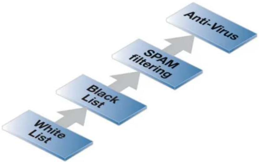
flowchart
graph TD
A["White List"] --> B["Black List"]
B --> C["SPAM filtering"]
C --> D["Anti-Virus"]
Figure 6.4. SMTP ALG Processing Order
Using Wildcards in White and Blacklists
Entries made in the white and blacklists can make use of wildcarding to have a single list entry cover a large number of potential email addresses. The wildcard character "*" is used to represent any sequence of characters of any length.
For instance, the list entry *@example.com can be used to specify all possible email addresses related to the domain example.com.
To explicitly allow emails destined for my_department, add the whitelist entry my_department@example.com and this will have precedence over the blacklist entry with the wildcard.
Enhanced SMTP and Extensions
Enhanced SMTP (ESMTP) is defined in RFC 1869 and allows a number extensions to the standard SMTP protocol.
When an SMTP client opens a session with an SMTP server using ESMTP, the client first sends an EHLO command. If the server supports ESMTP it will respond with a list of the extensions that it supports. These extensions are defined by various separate RFCs. For example, RFC 2920 defines the SMTP Pipelining extension. Another common extension is Chunking which is defined in RFC 3030.
The NetDefendOS SMTP ALG does not support all ESMTP extensions including Pipelining and Chunking. The ALG therefore removes any unsupported extensions from the supported extension list that is returned to the client by an SMTP server behind the firewall. When an extension is removed, a log message is generated with the text:
unsupported_extension capability_removed
The parameter "capa=" in the log message indicates which extension the ALG removed from the server response. For example, this parameter may appear in the log message as:
capa=PIPELINING
To indicate that the pipelining extension was removed from the SMTP server reply to an EHLO client command.
Although ESMTP extensions may be removed by the ALG and related log messages generated, this does not mean that any emails are dropped. Email transfers will take place as usual but without making use of unsupported extensions removed by the ALG.
Example 6.10. SMTP ALG Setup Using an IP Policy
In this example, an SMTP ALG is to be used to monitor email traffic that is flowing to a mail server on a DMZ network from the Internet. It is assumed that the mail server has a private IPv4 address which is defined by the address book object mail_server_ip so a SAT IP rule will be needed to translate the firewall's public IP address to this private address. The scenario is illustrated in the diagram below.
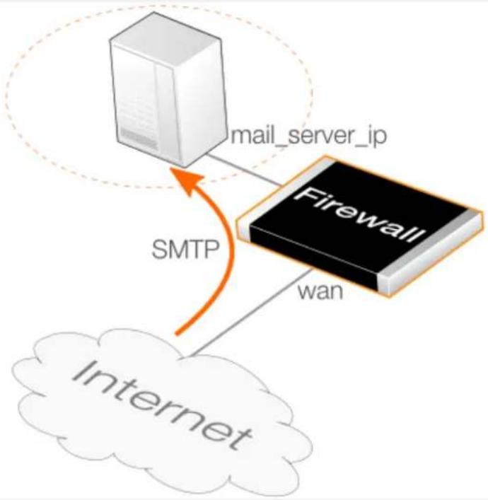
flowchart
graph TD
A["Server"] -->|mail_server_ip| B["Firewall"]
B -->|wan| C["Internet"]
D["SMTP"] --> A
It is assumed that the wan interface of the firewall is connected to the Internet and the public IP address of the interface is defined by the wan_ip address book object.
The SMTP ALG will be set up to perform the following actions:
• Block any attached .exe or .msi files.
- Block any attachments where the file extension differs from the file's MIME type.
- Scan any remaining attachments for viruses and do not allow them through if a virus is detected.
- Tag any mails flagged as SPAM by a DNSBL lookup at b.barracudacentral.org (weighted 5) and dnsbl.dronebl.org (weighted 3).
- Drop any mails that come from the domain example.com.
Command-Line Interface
A. Create a new Service object for inbound SMTP traffic:
gw-world:/> add Service ServiceTCPUDP smtp_inbound_service
Type=TCP
DestinationPorts=25
SYNRelay=Yes
Protocol=SMTP
B. Create an EmailControlProfile object:
gw-world:/> add Policy EmailControlProfile my_ec_profile
AntiSpam=Yes
DNSBL=Yes
DNSBL1=Yes
DNSBL1Name=b.barracudacentral.org
DNSBL1Score=5
DNSBL2=Yes
DNSBL2=dnsbl1.droneb1.org
DNSBL2Score=3
Add the blacklisted email source as a child of the profile:
gw-world:/> cc Policy EmailControlProfile my_ec_profile
gw-world:/my_ec_profile> add EmailFilter
SrcEmail = *@example.com
SrcType=Email
Action=Blacklist
gw-world:/my_ec_profile> cc
gw-world:/>
C. Create an AntiVirusPolicy object:
gw-world:/> add Policy AntiVirusPolicy my_av_policy
D. Create a FileControlPolicy object:
gw-world:/> add Policy FileControlPolicy my_fc_policy
FileListType=Block
File=exe,msi
VerifyContentMimeType=Yes
E. Create an IP Policy for email traffic from the Internet:
gw-world:/> add IPPolicy Name=smtp_inbound_sat
SourceInterface=wan
SourceNetwork=all_nets
DestinationInterface=core
DestinationNetwork=wan_ip
Service=smtp_inbound_service
Action=Allow
SourceAddressTranslation=None
DestinationAddressTranslation=SAT
DestinationAddressAction=SingleIP
DestNewIP=mail_server_ip
EmailControl=Yes
EC_Policy=my_ec_profile
AntiVirus=Yes
AV_Mode=UsePolicy
AV_Policy=my_av_policy
FileControl=Yes
FC_Mode=UsePolicy
FC_Policy=my_fc_policy
Web Interface
A. Create a new Service object for inbound SMTP:
1. Go to: Objects > Services > Add > TCP/UDP Service
-
Now enter:
-
Name: smtp_inbound_service
- Type: TCP
- Destination: 110
- Enable SYN Flood Protection
- Protocol: SMTP
3. Click OK
B. Create an Email Control Profile object:
-
Go to: Policies > Firewalling > Email Control > Add > Email Control Profile
-
Now enter:
- Name: my_ec_profile
- Under General enter:
• ANTI-SPAM: ON
• DNS Blacklists: Enable
• Blacklist1: 5, b.barracudacentral.org
• Blacklist2: 3, dnsb1.droneb1.org
- Under Whitelist/Blacklist select Add > Email Filter and enter:
• Action: Blacklist
• Source Type: Email Address
• Source Email Address: *@example.com
- Select OK
- Select OK
C. Create an Anti-Virus Profile object:
-
Go to: Policies > Firewalling > Anti-Virus > Add > Anti-Virus Profile
-
Now enter:
- Name: my_av_profile
- Select OK
D. Create a File Control Profile object:
-
Go to: Policies > Firewalling > File Control > Add > File Control Profile
-
Now enter:
- Name: my_fc_profile
• File Type Action: Block
- File Types: exe.msi
- Validate File Extension: Enabled
- Select OK
E. Create an IP Policy for email traffic to the mail server from the Internet:
-
Go to: Policies > Firewalling > Main IP Rules > Add > IP Policy
-
Now enter:
-
Name: smtp_inbound_sat
-
Action: Allow
-
Under Filter enter:
-
Source Interface: wan
- Source Network: all-nets
- Destination Interface: core
-
Destination Network: wan_ip
• Service: smtp_inbound_service -
Under Source Translation enter:
- Address Translation: None
-
Under Destination Translation enter:
-
Address Translation: SAT
• Address Action: Single IP
• New IP Address: mail_server_ip -
Under Email Control enter:
-
Enable Email Control: ON
-
Email Control Profile: my_ec_profile
-
Under Anti-Virus enter:
-
Enable Anti-Virus: ON
-
Anti-Virus Profile: my_av_profile
-
Under File Control enter:
-
Enable File Control: ON
• File Control Profile: my_fc_profile -
Click OK
SMTP ALG Setup with IP Rules
To set up security using the SMTP ALG, perform the following steps:
-
Create a new SMTP ALG object with the desired options enabled, such as file blocking and virus scanning.
-
Create a new custom Service object for SMTP with the following properties:
i. Type: TCP
ii. Destination: 25
iii. Enable Syn Flood Protection if traffic is coming from the Internet.
iv. ALG: Assign the service from the previous step.
- Create an IP Rule object that that uses the Service from the previous step. Multiple rules will be needed for SAT address translation.
Example 6.11. SMTP ALG Setup with IP Rules
This example repeats Example 6.10, "SMTP ALG Setup Using an IP Policy" but uses IP rules instead of a single IP policy.
Command-Line Interface
A. Create an SMTP ALG object:
gw-world:/> add ALG ALG_SMTP smtp_inbound_alg
FileListType=Block
File=exe,msi
VerifyContentMimetype=Yes
Antivirus=Protect
DNSBL=Yes
DNSBlackLists={b.barracudacentral.org;5},{dnsbl.dronebl.org;3}
Also in this ALG, blacklist all mails sent from the example.com domain:
gw-world:/> cc ALG ALG_SMTP smtp_inbound_alg
gw-world:/smtp_inbound_alg> add ALG_SMTP_Email
Action=Blacklist
Type=Sender
Email=*@example.com
gw-world:/smtp_inbound_alg> cc
gw-world:/>
B. Create a new Service object for inbound SMTP traffic:
gw-world:/> add Service ServiceTCPUDP smtp_inbound_service
Type=TCP
DestinationPorts=25
SYNRelay=Yes
ALG=smtp_inbound_alg
C. Create an IP Rule for email traffic from the Internet:
i. Create a SAT IP rule to translate the server address:
gw-world:/> add IPRule Action=SAT
SourceInterface=wan
SourceNetwork=all_nets
DestinationInterface=core
DestinationNetwork=wan_ip
Service=smtp_inbound_service
SATTranslate=DestinationIP
SATTranslateToIP=mail_server_ip
Name=smtp_inbound_sat
ii. Create a matching ALLOW IP rule to permit the translated traffic:
gw-world:/> add IPRule Action=Allow
SourceInterface=wan
SourceNetwork=all_nets
DestinationInterface=core
DestinationNetwork=wan_ip
Service=smtp_inbound_service
Name=smtp_inbound_allow
Web Interface
A. Create an SMTP ALG object:
- Go to: Objects > ALG > Add > SMTP ALG
- Under General enter:
- Name: SMTP_inbound_alg
- Under File Integrity enter:
- Select exe and msi for blocked file types
-
Enable the option Block file with extension that does not match MIME type
-
Under Anti-Virus enter:
- Mode: Protect
-
Under Anti-Spam enter:
-
Enable DNS Anti-Spam Filter
-
Under DNS Blacklists add b.barracudacentral.org with a value of 5 and dnsbl.dronebl.org with a value of 3.
-
Under Whitelist/Blacklist select Add and enter:
• Action: Blacklist
- Type: Sender
- Email: *.@example.com
- Click OK
B. Create a new Service object for inbound SMTP:
- Go to: Objects > Services > Add > TCP/UDP Service
- Now enter:
-
Name: smtp_inbound_service
-
Type: TCP
- Destination: 110
- Enable SYN Flood Protection
- ALG: smtp_inbound_alg
3. Click OK
C. Create an IP Rule for email traffic to the mail server from the Internet:
i. Create a SAT IP rule to translate the server address:
-
Go to: Policies > Firewalling > Main IP Rules > Add > IP Rule
-
Now enter:
-
Name: smtp_inbound_sat
• Action: SAT
• Service: smtp_inbound_service - Source Interface: wan
- Source Network: all-nets
- Destination Interface: core
- Destination Network: wan_ip
• SAT Translate: Destination IP
• New IP Address: mail_server_ip
3. Click OK
ii. Create a matching ALLOW IP rule to permit the translated traffic:
-
Go to: Policies > Firewalling > Main IP Rules > Add > IP Rule
-
Now enter:
-
Name: smtp_inbound_allow
- Action: Allow
• Service: smtp_inbound_service - Source Interface: wan
• Source Network: all-nets - Destination Interface: core
- Destination Network: wan_ip
3. Click OK
6.1.5.1. ZoneDefense with the SMTP ALG
ZoneDefense is a feature that allows NetDefendOS to block hosts and networks by sending management commands to certain types of external network switches. SMTP is used for both mail clients that want to send emails as well as mail servers that relay emails to other mail servers. When using ZoneDefense together with the SMTP ALG, the only scenario of interest is to block local clients that try to spread viruses in outgoing emails.
Using ZoneDefense for blocking relayed emails to an incoming SMTP server would be inadvisable since it would disallow all incoming emails from the blocked email server. For example, if a remote user is sending an infected email using a well-known free email company, blocking the sending server using ZoneDefense would block all future emails from that same company to any local receiver. Using ZoneDefense together with the SMTP ALG should therefore be used principally for blocking local email clients.
To implement blocking, the administrator configures the ZoneDefense network range to include all local SMTP clients. The SMTP-server itself should be excluded from this range.

Tip: Exclusion can be manually configured
It is possible to manually configure certain hosts and servers to be excluded from being blocked by adding them to the ZoneDefense Exclude List.
When a client tries to send an email infected with a virus, the virus is blocked and ZoneDefense isolates the host from the rest of the network.
Setup Steps
The steps to setting up ZoneDefense with the SMTP ALG are:
- Configure the ZoneDefense switches to be used with ZoneDefense by going to the ZoneDefense section of the Web Interface.
- Set up the SMTP ALG to use Anti-Virus scanning in enabled mode. With an IP policy this done by defining an Anti-Virus policy object and associating it with the policy.
- Choose the ZoneDefense network in the Anti-Virus configuration that is to be affected by ZoneDefense when a virus is detected.
More information about this topic can be found in Section 7.9, "ZoneDefense".
6.1.6. POP3 ALG
POP3 is a mail transfer protocol that is used by a recipient's email client to download emails from a mail server. The principal difference with the IMAP protocol is that the entire email and any attachments are downloaded to the client before the email can be examined. The email is then subsequently stored on the client computer and may be deleted from the mail server.
The diagram below illustrates a typical usage of the NetDefendOS POP3 ALG. A mail server located on the DMZ network dmz_net receives emails from the Internet using the SMTP protocol. A protected client on the lan_net network downloads emails from this server using the POP3 protocol. The clients initiate the transfer with POP3, sending a request to the mail server for the download of emails also using POP3.
As the emails traverse the firewall, the NetDefendOS POP3 ALG examines the data and can block or allow them according to the behavior specified in the ALG configuration object.
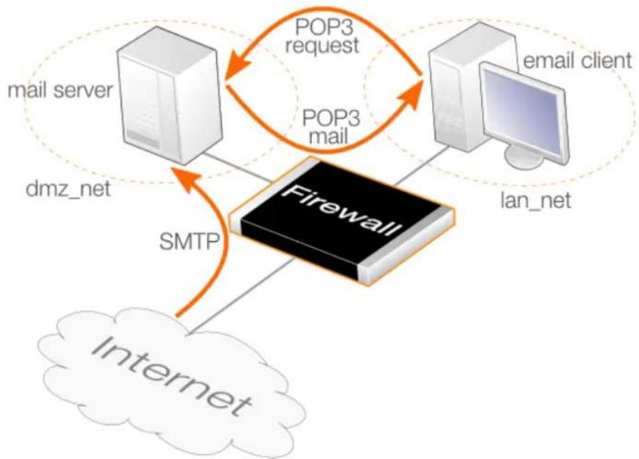
flowchart
graph TD
A["mail server"] -->|POP3 request| B["Firewall"]
C["email client"] -->|POP3 mail| B
D["Internet"] -->|SMTP| B
B -->|dmz_net| A
B -->|lan_net| C
Figure 6.5. POP3 ALG Usage
In this scenario, the SMTP traffic arriving at the mail server on the DMZ also traverses the firewall and this traffic can be examined using the NetDefendOS SMTP ALG. This is discussed further in Section 6.1.5, "SMTP ALG".
Methods of Setting Up the POP3 ALG
Deploying the POP3 ALG can be done using one of the following methods:
• Using IP Policies
Using an IP Policy object is the recommended setup method. It is easiest and provides additional options that are not available with IP rules. Note that to configure POP3 options with an IP policy, the policy's Service property must be assigned a service object which has its Protocol property set to POP3.
- Using IP Rules
When using IP Rule objects, a POP3 ALG object is associated with a Service object that is then associated with an IP rule.
This setup method can be useful for compatibility with older NetDefendOS versions but does not provide any advantages over using an IP policy.
POP3 ALG Setup Using an IP Policy
Setting up the POP3 ALG with an IP policy is done with the following steps:
- Create a new service object which is a copy of the predefined pop3 service and set its
Protocol property to POP3. Alternatively, set the Protocol property of the predefined service called pop3 to the value POP3 and use that.
- Create a new IP Policy object that triggers on the targeted traffic and set its Service property to be the service object from the previous step. These will make all the POP3 ALG options available on the IP policy.
- Create and configure a new Email Control Profile and assign it to the IP policy.
- Optionally also assign a newly created File Control Profile and/or a Anti-Virus Profile to apply those features to the POP3 traffic. Application control can also be configured on the IP policy.
POP3 ALG Options
When using an IP policy, the POP3 ALG is enabled by associating an Email Control Profile object with the policy. The following options are configurable on the Email Control Profile for POP3:
- SPAM Filtering
Emails can be filtered for SPAM. This is described further in Section 6.3.1, "Email Control Profiles with IP Policies".
Anti-Spam scanning by the POP3 ALG can be redundant if scanning is already performed on mail traffic before it reaches the mail server. This scanning could be done by the NetDefendOS SMTP ALG.
- Hide User
This option prevents the POP3 server from revealing that a username does not exist. This prevents users from trying different usernames until they find a valid one. With an IP policy, this is found in the Email Control Profile and is disabled by default.
- Allow Unknown Commands
Non-standard POP3 commands not recognized by the ALG can be allowed or disallowed. With an IP policy, this is found in the Email Control Profile and is disabled by default.
- Block USER/PASS Commands
Block connections between client and server that send the username/password combination as clear text which can be easily read (some servers may not support other methods than this). With an IP policy, this is found in the Email Control Profile and is disabled by default.
- Allow STARTTLS
This allows STARTTLS commands in the POP3 negotiation. By default, this is disabled.
Other Options
The following options can also be configured on an IP policy that triggers on POP3 traffic:
- File Control
A File Control Profile can be associated with an IP policy to place checks on files transferred.
With IP rules, this option is configured on the POP3 ALG object used.
- Anti-Virus scanning
An Anti Virus Profile can be associated with an IP policy to scan transferred files for viruses.
With IP rules, this option is configured on the POP3 ALG object.
- Application Control
Application control can be applied to POP3 traffic. This is described further in Section 3.7, "Application Control".
This option is not available with IP rules.
Example 6.12. POP3 ALG Setup Using an IP Policy
This example will assume the network topology illustrated in the diagram at the beginning of this section. POP3 traffic is to be allowed between a mail server on the dmz_net network and protected clients on the lan_net network. It is assumed that the mail server has a private IPv4 address which is defined by the address book object mail_server_ip.
The POP3 ALG will perform the following actions:
- Prevent the mail server revealing if the email address exists.
- Deny any email that fails scanning by the ALG.
• Block all attached exe or msifiles. - Block any attachments where the file extension differs from the file's MIME type.
- Scan all allowed attachments for viruses.
Note that clients will initiate POP3 connections so they will be the source network for the IP policy.
Command-Line Interface
A. Create a new Service object for POP3:
gw-world:/> add Service ServiceTCPUDP pop3_client_service
Type=TCP
DestinationPorts=110
Protocol=POP3
B. Create an EmailControlProfile object:
gw-world:/> add Policy EmailControlProfile my_ec_profile HideUser=Yes
C. Create an AntiVirusPolicy object:
gw-world:/> add Policy AntiVirusPolicy my_av_policy
D. Create an FileControlPolicy object:
gw-world:/> add Policy FileControlPolicy my_fc_policy
FileListType=Block
File=exe,msi
VerifyContentMimeType=Yes
E. Create an IP Policy for email traffic from the mail server:
gw-world:/> add IPPolicy Name=pop3_policy
SourceInterface=lan
SourceNetwork=lan_net
DestinationInterface=dmz
DestinationNetwork=mail_server_ip
Service=pop3_client_service
Action=Allow
SourceAddressTranslation=None
EmailControl=Yes
EC_Policy=my_ec_profile
AntiVirus=Yes
AV_Mode=UsePolicy
AV_Policy=my_av_policy
FileControl=Yes
FC_Mode=UsePolicy
FC_Policy=my_fc_policy
Web Interface
A. Create a new Service object for POP3:
- Go to: Objects > Services > Add > TCP/UDP Service
-
Now enter:
-
Name: pop3_client_service
- Type: TCP
- Destination: 110
-
Protocol: POP3
-
Click OK
B. Create an Email Control Profile object:
-
Go to: Policies > Firewalling > Email Control > Add > Email Control Profile
-
Now enter:
- Name: my_ec_profile
- Under POP3 enter:
- Hide User: Enabled
- Select OK
C. Create an Anti-Virus Profile object:
-
Go to: Policies > Firewalling > Anti-Virus > Add > Anti-Virus Profile
-
Now enter:
- Name: my_av_profile
3. Select OK
D. Create an File Control Profile object:
-
Go to: Policies > Firewalling > File Control > Add > File Control Profile
-
Now enter:
-
Name: my_fc_profile
- File Type Action: Block
- File Types: exe.msi
- Validate File Extension: Enabled
3. Select OK
E. Create an IP Policy for email traffic from the mail server:
-
Go to: Policies > Firewalling > Main IP Rules > Add > IP Policy
-
Now enter:
-
Name: pop3_policy
• Action: Allow -
Under Filter enter:
-
Source Interface: Ian
- Source Network: lan_net
- Destination Interface: dmz
-
Destination Network: mail_server_ip
• Service: pop3_client_service -
Under Source Translation enter:
- Address Translation: None
-
Under Email Control enter:
-
Enable Email Control: ON
-
Email Control Profile: my_ec_profile
-
Under Anti-Virus enter:
-
Enable Anti-Virus: ON
• Anti-Virus Profile: my_av_profile -
Under File Control enter:
- Enable File Control: ON
- File Control Profile: my_fc_profile
- Click OK
POP3 ALG Setup Using IP Rules
Setting up the POP3 ALG with an IP Rule requires the following steps:
-
Create a new POP3 ALG object with the desired options enabled, such as file blocking and virus scanning. There is no predefined POP3 ALG in NetDefendOS.
-
Create a new custom Service object for POP3 with the following properties:
i. Type: TCP
ii. Destination: 110
This is now a copy of the predefined Service object called pop3. This predefined object could be used instead.
-
Associate the new POP3 ALG object with the newly created Service object.
-
Create an IP Rule object that has the mail server as its Destination Network and the email clients as its Source Network since it is the clients which will initiate connections.
-
Associate the Service object with the IP rule.
Example 6.13. POP3 ALG Setup Using IP Rules
This example will repeat the scenario found in Example 6.12, "POP3 ALG Setup Using an IP Policy" but will use an IP Rule instead if an IP Policy.
Command-Line Interface
A. Create a POP3 ALG object:
gw-world:/> add ALG ALG_POP3 pop3_client_alg
HideUser=Yes
FileListType=Block
File=exe,msi
VerifyContentMimetype=Yes
Antivirus=Protect
B. Create a new Service object for POP3:
gw-world:/> add Service ServiceTCPUDP pop3_client_service
Type=TCP
DestinationPorts=110
ALG=pop3_client_alg
C. Create an IP Rule for email traffic from the mail server:
gw-world:/> add IPRule Action=Allow
SourceInterface=lan
SourceNetwork=lan_net
DestinationInterface=dmz
DestinationNetwork=mail_server_ip
Service=pop3_client_service
Name=pop3_mail
Web Interface
A. Create a POP3 ALG object:
- Go to: Objects > ALG > Add > POP3 ALG
-
Under General enter:
-
Name: pop3_client_alg
-
Enable the option Prevent a user from revealing a user does not exist
-
Under File Integrity enter:
-
Select exe and msi for blocked file types
-
Enable the option Block file with extension that does not match MIME type
-
Under Anti-Virus enter:
- Mode: Protect
- Click OK
B. Create a new Service object for POP3:
- Go to: Objects > Services > Add > TCP/UDP Service
-
Now enter:
-
Name: pop3_client_service
- Type: TCP
- Destination: 110
-
ALG: pop3_client_alg
-
Click OK
C. Create an IP Rule for email traffic from the mail server:
- Go to: Policies > Firewalling > Main IP Rules > Add > IP Rule
- Now enter:
- Name: pop3_mail
- Action: Allow
• Service: pop3_client_service
- Source Interface: Ian
- Source Network: lan_net
- Destination Interface: dmz
- Destination Network: mail_server_ip
3. Click OK
Note that clients initiates the POP3 connection so they are the source for the IP rule.
6.1.7. IMAP ALG
IMAP is a mail transfer protocol that is used by a recipient's email client to download emails from a mail server. The principal difference with the POP3 protocol is that the entire email and any attachments are not downloaded to the client along with the email header. Instead, only the mail header is downloaded and the user can then choose to read the body in which case the whole email with any attachments is downloaded. Alternatively, a mail could be deleted on the server without the rest of the email ever being downloaded to the client.
Setting Up the IMAP ALG
Deploying the IMAP ALG can only be done using an IP policy and requires the following steps:
- Create a new service object which is a copy of the predefined imap service and set its Protocol property to IMAP. Alternatively, set the Protocol property of the predefined service called imap to the value IMAP and use that.
- Create a new IP Policy object that triggers on the targeted traffic and set its Service property to be the service object from the previous step. These will make all the IMAP ALG options available on the IP policy.
- Create and configure a new Email Control Profile and assign it to the IP policy.
- Optionally also assign a newly created File Control Profile and/or a Anti-Virus Profile to apply those features to the IMAP traffic. Application control can also be configured on the IP policy.
IMAP ALG Options
When using an IP policy, the IMAP ALG is enabled by associating an Email Control Profile object with the policy. The following options are configurable on the Email Control Profile for IMAP:
- SPAM Filtering
Emails can be filtered for SPAM. This is described further in Section 6.3.1, "Email Control Profiles with IP Policies" and that section also includes details about how NetDefendOS SPAM filtering differs for the IMAP protocol.
Anti-Spam scanning by the IMAP ALG can be redundant if scanning is already performed on mail traffic before it reaches the mail server. This scanning could be done by the NetDefendOS SMTP ALG.
- Hide User
If the wrong credentials are sent to this server, enabling this option prevents the server's error message being returned to the client. Some servers might send an error message which gives an indication which of the credentials is incorrect and this could be helpful in a security attack. Instead, NetDefendOS will send back its own general error message to the client.
By default, this option is disabled.
• Block Plain Text Authentication
When enabled, authentication using credentials sent in plain text will be blocked.
- Allow STARTTLS
This allows STARTTLS commands in the IMAP negotiation. By default, this is disabled.
Other Options
The following options can also be configured on an IP policy that triggers on IMAP traffic:
- File Control
A File Control Profile can be associated with an IP policy to place checks on files transferred.
- Anti-Virus scanning
An Anti Virus Profile can be associated with an IP policy to scan transferred files for viruses.
- Application Control
Application control can be applied to IMAP traffic. This is described further in Section 3.7, "Application Control".
Example 6.14. IMAP ALG Setup
This example shows how to set up an IP Policy object which allows internal clients on lan_net to retrieve email from a mail server located on dmz_net using the IMAP protocol. This retrieval is illustrated below.
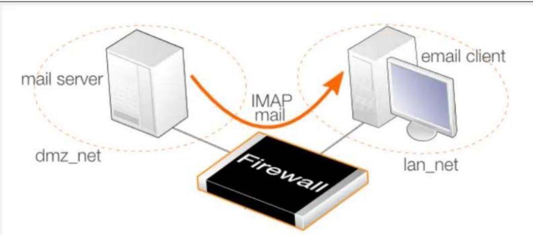
flowchart
graph TD
A["mail server"] -->|IMAP mail| B["email client"]
B --> C["lan_net"]
C --> D["Firewall"]
D -->|dmz_net| A
The additional requirements are as follows:
- Enable the anti-spam function.
- Whitelist all mails from example.com so they are never dropped or marked as spam.
- Assign a sub-score of 5 to both domain verification and link protection
- Change the subject line text so ***Probably SPAM *** is added for spam.
• Use the single DNSBL server at b.barracudacentral.org.
Command-Line Interface
A. Create an EmailControlProfile object for filtering the mail:
gw-world:/> add Policy EmailControlProfile my_email_profile
AntiSpam=Yes
SubjectTag="*** Probably SPAM ***"
DomainVerificationScore=5
LinkProtectionScore=5
DNSBL=Yes
DNSBL1=Yes
DNSBL1Name=b.barracudacentral.org
B. Add an EmailFilter object to the profile for whitelisting:
Change the CLI context to be the profile:
gw-world:/> cc EmailProfile my_email_profile
Add an EmailFilter object as a child:
gw-world:/my_email_profile> add EmailFilter
Action=Whitelist
SrcType=Email
SrcEmail=*@example.com
Return to the default CLI context:
gw-world:/main> cc
gw-world:/>
C. Create a custom Service for IMAP:
Command-Line Interface
gw-world:/> add Service ServiceTCPUDP my_imap_service
Type=TCP
DestinationPorts=143
Protocol=IMAP
D. Add an IPPolicy to allow IMAP traffic and associate the profile with it:
gw-world:/> add IPPolicy Name=lan_to_dmz
SourceInterface=lan
SourceNetwork=lan_net
DestinationInterface=dmz
DestinationNetwork=dmz_net
Service=my_imap_service
Action=Allow
SourceAddressTranslation=None
EmailControl=Yes
EC_Policy=my_email_profile
Web Interface
A. Create an Email Control Profile object for filtering the mail:
1. Go to: Policies > Firewalling > Email Control > Add > Email Control Profile
2. Now enter:
• Name: my_email_profile
• Anti-Spam: Enable
• Domain Verification Score: 5
• Malicious Link Protection Score: 5
• DNS Blacklists: Enable
• Blacklist 1: b.barracudacentral.org
• Tag Subject Text: *** Probably SPAM ***
- Select OK
B. Add an EmailFilter object to the profile for whitelisting:
1. Go to: Policies > Firewalling > Email Control
2. Select my_email_profile
3. Select Whitelist/Blacklist
4. Select Add > Email Filter
5. Now enter:
• Action: Whitelist
• Source Type: Email Address
• Source Email Address: *@example.com
- Select OK
- Select OK
C. Create a custom Service for IMAP:
Web Interface
- Go to: Objects > Services > Add > TCP/UDP Service
-
Now enter:
-
Type: TCP
- Destination: 143
-
Protocol: IMAP
-
Click OK
D. Add an IP Policy to allow IMAP traffic and associate the profile with it:
- Go to: Policies > Firewalling > Add > IP Policy
-
Now enter:
-
Name: lan_to_dmz
-
Action: Allow
-
Under Filter enter:
-
Source Interface: Ian
- Source Network: Ian_net
- Destination Interface: dmz
-
Destination Network: dmz_net
• Service: my_imap_service -
Under Source Translation enter:
- Address Translation: None
-
Under Email control enter:
-
Enable Email Control: Enable
-
Email Control Profile: my_email_profile
-
Select OK
6.1.8. PPTP ALG
The PPTP ALG is provided to deal with a specific issue when PPTP tunnels are used with NAT.
Suppose there are two clients A and B on a protected inner network behind a D-Link firewall. The firewall is connected to the external Internet and a NAT IP policy is defined to allow traffic from the clients to flow to the Internet. Both clients will therefore appear to have from the same IP address as they make connections to servers across the Internet.
One client A now establishes a PPTP tunnel to an external host C across the Internet. The tunnel endpoints are the client and the external server. Because of the NAT IP rule, the tunnel connection will appear to be coming from the external IP address on the firewall.
This first connection will be successful but when the second client B also tries to connect to the same server C at the same endpoint IP address, the first connection for A will be lost. The reason is that both clients are trying to establish a PPTP tunnel from the same external IP address to the same endpoint.
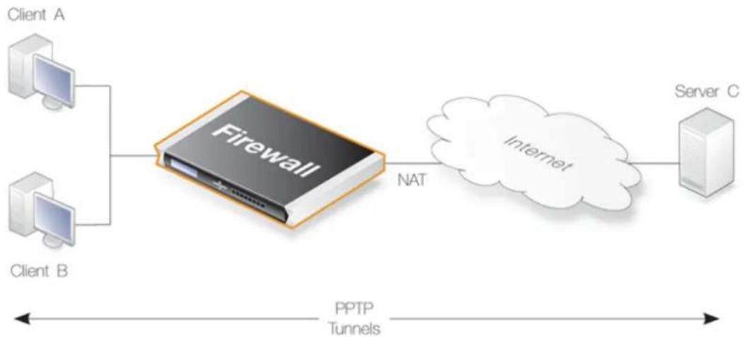
flowchart
graph LR
Client_A["Client A"] --> Firewall["Firewall"]
Client_B["Client B"] --> Firewall
Firewall -->|NAT| Internet["Internet"]
Internet --> Server_C["Server C"]
Client_A -->|PPTP Tunnels| Firewall
Client_B -->|PPTP Tunnels| Firewall
Server_C -->|PPTP Tunnels| Firewall
Figure 6.6. PPTP ALG Usage
The PPTP ALG solves this problem. By using the ALG, the traffic from all the clients can be multiplexed through a single PPTP tunnel between the firewall and the server.
Methods of Setting Up the PPTP ALG
Deploying the PPTP ALG can be done using one of the following methods:
• Using IP Policies
Using an IP Policy object is the recommended setup method. Note that to configure PPTP options with an IP policy, the policy's Service property must be assigned a service object which has its Protocol property set to TLS.
• Using IP Rules
When using IP Rule objects, a PPTP ALG object is associated with a Service object that is then associated with an IP rule.
This setup method can be useful for compatibility with older NetDefendOS versions but does not provide any advantages over using an IP policy.
PPTP ALG Setup Using an IP Policy
This section will discuss setting up the PPTP ALG using an IP Policy object. This is done with the following steps:
- Create a new custom TCP/UDP service object with the following properties:
i. Set Type to TCP.
ii. The Source port range can be left at the default range of 0-65535.
iii. Set Destination to 1723 (the port number).
iv. Set Protocol to PPTP.
Alternatively, set the Protocol property of the predefined service called pptp-ctl to the value PPTP and use that.
- Create a new IP Policy object that triggers on the targeted traffic and set its Service property to be the service object from the previous step. These will make the PPTP ALG options available on the IP policy.
- Make any adjustments to how the PPTP ALG behaves by changing the relevant properties of the IP Policy. The available options are discussed next.
PPTP ALG Options
The following options can be set on an IP Policy object once the Service for the PPTP protocol is associated with it:
- Enable PPTP settings
Set this to ON to activate the PPTP ALG.
- Echo timeout
Idle timeout period for echo messages inside the PPTP tunnel.
- Idle timeout
Idle timeout for user traffic messages in the PPTP tunnel.
In most scenarios these settings can be left at their defaults values.
Example 6.15. PPTP ALG Setup Using an IP Policy
This example adds a NAT IP policy that will perform address translation for all PPTP traffic originating from the internal network lan flowing to the Internet on the wan interface. The IP address of the wan interface will be used as the NATing address for all connections.
The PPTP ALG will be applied to the traffic and the default PPTP ALG settings will be used. The clients on lannet are the local endpoint of the PPTP tunnels. The table below summarizes the setup.
| Action | Src Interface | Src Network | Dest Interface | Dest Network | Service |
| Allow/NAT | lan | lannet | wan | all-nets | pptp_ctl |
Command-Line Interface
gw-world:/> add IPPolicy Name=nat_pptp
SourceInterface=lan
SourceNetwork=lannet
DestinationInterface=wan
DestinationNetwork=all-nets
Service=pptp-ctl
Action=Allow
SourceAddressTranslation=NAT
NATSourceAddressAction=OutgoingInterfaceIP
PPTPControl=Yes
Web Interface
- Go to: Policies > Firewalling > Main IP Rules > Add > IP Policy
-
Now enter:
-
Name: nat_pptp
-
Action: Allow
-
Under Filter enter:
-
Source Interface: Ian
- Source Network: Iannet
- Destination Interface: wan
- Destination Network: all-nets
-
Service: pptp_ctl
-
Under Source Translation enter:
-
Address Translation: NAT
• Address Action: Outgoing Interface IP -
Under PPTP enter:
- Enable PPTP settings: ON
- Click OK
PPTP ALG Setup Using an IP Rule
Although using an IP policy is the recommended method for deploying a PPTP ALG, an alternative but more complicated method is to use an IP Rule object instead. The sequence of steps for setup is as follows:
- Define a new PPTP ALG object with an appropriate name. There is no predefined PPTP ALG.
- Associate the ALG object with an appropriate Service object. The predefined service called pptp-ctl can be used for this purpose or a custom service can be created that is a copy of
pptp-ctl.
• Make any desired changes to the ALG's properties.
- Associate this service object with the NAT IP rule that permits the traffic to flow from clients to the remote endpoint of the PPTP tunnel. This may be an IP rule that NATs the traffic out to the Internet with a destination network of all-nets.
6.1.9. SIP ALG
Overview
Session Initiation Protocol (SIP) is an ASCII (UTF-8) text based signaling protocol used to establish sessions between clients in an IP network. It is a request-response protocol that resembles HTTP and SMTP. The session which SIP sets up might consist of a Voice-Over-IP (VoIP) telephone call or it could be a collaborative multi-media conference. Using SIP with VoIP means that telephony can become another IP application which can integrate into other services.
SIP Sets Up Sessions
SIP does not know about the details of a session's content and is only responsible for initiating, terminating and modifying sessions. Sessions set up by SIP are typically used for the streaming of audio and video over the Internet using the RTP/RTCP protocol (which is based on UDP) but they might also involve traffic based on the TCP protocol. An RTP/RTCP based session might also involve TCP or TLS based traffic in the same session.
The SIP RFC
SIP is defined by IETF RFC 3261 and this is considered an important general standard for VoIP communication. It is comparable to H.323, however, a design goal with SIP was to make SIP more scalable than H.323. (For VoIP, see also Section 6.1.10, "H.323 ALG".)

Important: Third Party Equipment Compliance
NetDefendOS is based on the SIP implementation described in RFC 3261. However, correct SIP message processing and media establishment cannot be guaranteed unless local and remote clients as well as proxies are configured to follow RFC 3261.
Unfortunately, some third party SIP equipment may use techniques that lie outside RFC 3261 and it may not be possible to configure the equipment to disable these. For this reason, such equipment may not be able to operate successfully with the NetDefendOS SIP ALG.
For example, analog to digital converters that do not work with the SIP ALG may come preconfigured by service providers with restricted configuration possibilities.
NAT traversal techniques like STUN also lie outside of RFC 3261 and need to be disabled.
NetDefendOS Supports Three Scenarios
Before continuing to describe SIP in more depth, it is important to understand that NetDefendOS supports SIP usage in three distinct scenarios:
- Protecting Local Clients
In this scenario, the proxy is located somewhere on the Internet.
• Protecting Proxy and Local Clients
Here, the proxy is located on the same network as the clients. However, this case can be divided into two scenarios:
i. The clients and proxy are on an internal, trusted network.
ii. The clients and proxy are on the DMZ network.
Configuration Limitations with SIP
The following NetDefendOS configuration limitations exist for SIP traffic passing through the SIP ALG:
- SIP ALG traffic cannot be configured with any other routing table except the main routing table. This means the NetDefendOS Virtual Routing feature cannot be configured, nor can policy-based routing (PBR) rules be used with the SIP ALG.
• The Route Failover feature cannot be used.
• Traffic shaping cannot be applied to SIP ALG traffic
SIP Components
The following components are the logical building blocks for SIP communication:
| User Agents | These are the endpoints or clients that are involved in the client-to-client communication. These would typically be the workstation or device used in an IP telephony conversation. The term client will be used throughout this section to describe a user agent. |
| Proxy Servers | These act as routers in the SIP protocol, performing both as client and server when receiving client requests. They forward requests to a client's current location as well as authenticating and authorizing access to services. They also implement provider call-routing policies.The proxy is often located on the external, unprotected side of the firewall but can have other locations. All of these scenarios are supported by NetDefendOS. |
| Registrars | A server that handles SIP REGISTER requests is given the special name of Registrar. The Registrar server has the task of locating the host where the other client is reachable.The Registrar and Proxy Server are logical entities and may, in fact, reside on the same physical server. |
SIP Media-related Protocols
A SIP session makes use of a number of protocols. These are:
SDP Session Description Protocol (RFC 4566) is used for media session initialization.
RTP Real-time Transport Protocol (RFC 3550) is used as the underlying packet format for delivering audio and video streaming via IP using the UDP protocol.
RTCP Real-time Control Protocol (RFC 3550) is used in conjunction with RTP to provide out-of-band control flow management.
Methods of Setting up the SIP ALG
Deploying the SIP ALG can be done using one of the following methods:
• Using a VoIP Profile object with an IP Policyobject
The SIP ALG can be configured using IP Policy objects and this is the recommended method. Setup is done by creating a VoIP Profile object and specifying SIP options on that. The VoIP Profile object is then associated with an IP Policy object that triggers on the target traffic.
A Service object configured for SIP traffic must also be used with the IP Policy object. This Service object must have its Protocol property set to SIP.
The predefined SIP service objects in the default configuration for NetDefendOS 11.03 and later already have their Protocol property set to be SIP. This will not be true where NetDefendOS has been upgraded to version 11.03 or later.
• Using a SIP ALG object with an IP Rule object
Alternatively, a SIP ALG object can be associated with a Service object configured for the SIP protocol. The service object is then used with the IP Rule objects that trigger on the SIP traffic flow.
In NetDefendOS version 11.03 and later, a predefined SIP ALG is not present in the default configuration and therefore a new SIP ALG object must always be created when using an IP Rule object with SIP. In older NetDefendOS versions that are upgraded to 11.03 or later, the predefined SIP ALG object will be retained.
SIP ALG Setup Using IP Policies
When configuring the SIP ALG using IP Policy objects, the following steps are required:
- Define a single Service object for SIP communication. The Protocol property must be set to SIP if the service is to be used with an IP Policy object.
- Define a VoIP Profile object and disable H.323 but leave SIP enabled. Change the SIP settings as required.
- Define the an IP Policy object that allows the SIP traffic, setting the Service property to the object created in the first step.
- Associate the VoIP Profile object created in the second step with the IP Policy object.
The Predefined SIP Service Could Be Used
The predefined Service object called sip-udp could be used as the service in the steps above. However, it is recommended to create a new, custom Service object and the examples given here
do this.
Note that any SIP service object used with IP policies must used have its Protocol property set to SIP and this may not already be the case with the predefined sip-udp object if there have been upgrades from much older NetDefendOS versions.
SIP ALG Options
The following options can be configured for the SIP ALG object. For IP policies, this is done on the VoIP object created:
- Max Sessions per ID
The number of simultaneous sessions that a single client can be involved with is restricted by this value. The default value is 5.
• Max Registration Time
The maximum time for registration with a SIP Registrar. The default value is 3600 seconds.
- SIP Signal Timeout
The maximum time allowed for SIP sessions. The default value is 43200 seconds.
- Data Channel Timeout
The maximum time allowed for periods with no traffic in a SIP session. A timeout condition occurs if this value is exceeded. The default value is 120 seconds.
- Allow TCP Data Channels
TCP data channels can be used during a SIP session. The is enabled by default.
• Max TCP Data Channels
If Allow TCP Data Channels is enabled this option is available to specify the maximum time number of TCP channels allowed in a SIP session. The default value is 10.
- Allow Media Bypass
If this option is enabled then data, such as RTP/RTCP communication, may take place directly between two clients without involving the firewall. This would only happen if the two clients were behind the same interface and belong to the same network. This setting is enabled by default.
The SIP Proxy Record-Route Option
To understand how to set up SIP scenarios with NetDefendOS, it is important to first understand the SIP proxy Record-Route option. SIP proxies have the Record-Route option either enabled or disabled. When it is switched on, a proxy is known as a Stateful proxy. When Record-Route is enabled, a proxy is saying it will be the intermediary for all SIP signaling that takes place between two clients.
When a SIP session is being set up, the calling client sends an INVITE message to its outbound SIP proxy server. The SIP proxy relays this message to the remote proxy server responsible for the called, remote client's contact information. The remote proxy then relays the INVITE message to the called client. Once the two clients have learnt of each other's IP addresses, they can communicate directly with each other and remaining SIP messages can bypass the proxies. This facilitates scaling since proxies are used only for the initial SIP message exchange.
The disadvantage of removing proxies from the session is that NetDefendOS IP rule set entries must be set up to allow all SIP messages through the firewall, and if the source network of the messages is not known then a large number of potentially dangerous connections must be allowed by the IP rule set. This problem does not occur if the local proxy is set up with the Record-Route option enabled. In this mode, all SIP messages will only come from the proxy.
The different entries required when the Record-Route option is enabled and disabled can be seen in the two different sets of IP rule set entries listed below in the detailed description of Scenario 1 Protecting local clients - Proxy located on the Internet.
IP Rule Set Entries for Media Data
When discussing SIP data flows there are two distinct types of exchanges involved:
- The SIP session which sets up communication between two clients prior to the exchange of media data.
- The exchange of the media data itself, for example the coded voice data which constitute a VoIP phone call.
In the SIP setups described below, IP rule set entries need only be explicitly defined to deal with the first of the above, which is the SIP exchanges needed for establishing client-to-client communications. No IP rule set entries or other objects need to be defined to handle the second of the above (the exchange of media data). The SIP ALG automatically takes care of creating the connections required (sometimes described as SIP pinholes) for allowing the media data traffic to flow through the firewall.

Tip
Make sure there are no preceding IP rule set entries that disallow the SIP traffic.
SIP ALG Usage Scenarios
NetDefendOS supports a variety of SIP ALG usage scenarios. The following three scenarios cover nearly all possible types of usage:
- Scenario 1
Protecting local clients - Proxy located on the Internet
The SIP session is between a client on the local, protected side of the D-Link firewall and a client which is on the external, unprotected side. The SIP proxy is located on the external, unprotected side of the firewall. Communication typically takes place across the Internet with clients on the internal, protected side registering with a proxy on the public, unprotected side.
- Scenario 2
Protecting proxy and local clients - Proxy on the same network as clients
The SIP session is between a client on the local, protected side of the D-Link firewall and a client which is on the external, unprotected side. The SIP proxy is located on the local, protected side of the firewall and can handle registrations from both clients located on the same local network as well as clients on the external, unprotected side. Communication can take place across the Internet or between clients on the local network.
- Scenario 3
Protecting proxy and local clients - Proxy on a DMZ interface
The SIP session is between a client on the local, protected side of the D-Link firewall and a client which is on the external, unprotected side. The SIP proxy is located on the DMZ interface and is physically separated from the local client network as well as the remote client network and proxy network.
All the above scenarios will also deal with the situation where two clients in a session reside on the same network. These scenarios will now be discussed in detail.
Scenario 1 Protecting local clients - Proxy located on the Internet
The scenario assumed is an office with VoIP users on a private internal network where the network's topology will be hidden using NAT. This is illustrated below.
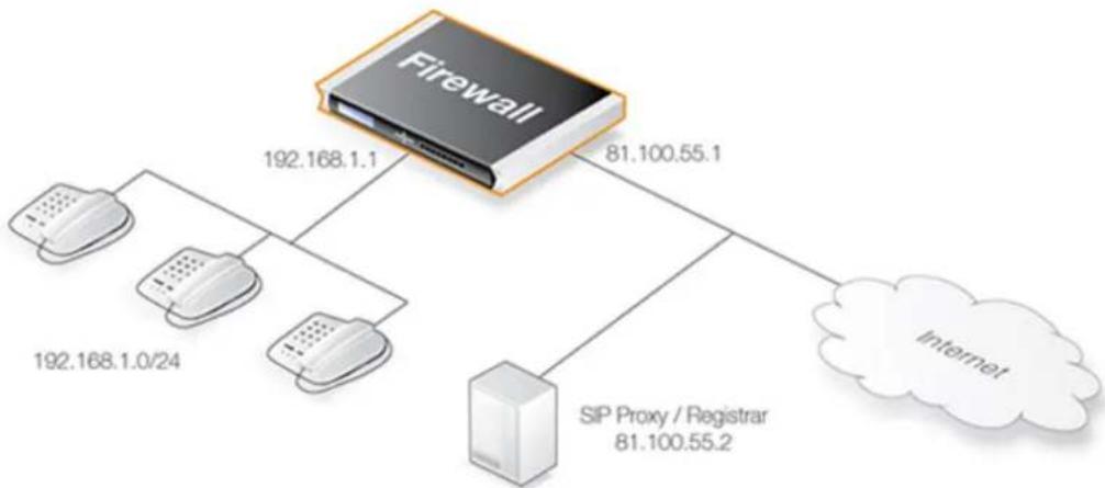
flowchart
graph TD
A["Firewall"] -->|192.168.1.1| B["IP Address"]
A -->|81.100.55.1| C["Internet"]
B -->|192.168.1.0/24| D["IP Address"]
A -->|SIP Proxy / Registrar 81.100.55.2| E["IP Address"]
The SIP proxy in the above diagram could alternatively be located remotely across the Internet. The proxy should be configured with the Record-Route feature enabled to ensure all SIP traffic to and from the office clients will be sent through the SIP Proxy. This is recommended since the attack surface is minimized by allowing only SIP signaling from the SIP Proxy to enter the local network.
This scenario can be implemented in two ways:
• Using NAT to hide the network topology.
• Without NAT so the network topology is exposed.

Note: NAT traversal should not be configured
SIP User Agents and SIP Proxies should not be configured to employ NAT Traversal in any setup. For instance the Simple Traversal of UDP through NATs (STUN) technique should not be used. The NetDefendOS SIP ALG will take care of all NAT traversal issues in a SIP scenario.
The setup steps for this scenario are as follows:
-
Define a SIP ALG object using the options described above.
-
Define a Service object and associate it with the SIP ALG object. The service should have the following properties:
• Destination Port: 5060 (the default SIP signaling port).
- Type: TCP/UDP
- Protocol: SIP
-
Define two IP rule set entries:
-
A NAT entry for outbound traffic from clients on the internal network to the SIP Proxy Server located externally. The SIP ALG will take care of all address translation needed by the NAT rule. This translation will occur both on the IP level and the application level. Neither the clients or the proxies need to be aware that the local users are being NATed.
- An Allow entry for inbound SIP traffic from the SIP proxy to the IP of the firewall. This rule will use core (in other words, NetDefendOS itself) as the destination interface. The reason for this is due to the NAT rule above. When an incoming call is received, NetDefendOS will automatically locate the local receiver, perform address translation and forward SIP messages to the receiver. This will be executed based on the ALGs internal state.
A SAT rule set entry for translating incoming SIP messages is not needed since the ALG will automatically redirect incoming SIP requests to the correct internal user. When a SIP client behind a NATing firewall registers with an external SIP proxy, NetDefendOS sends its own IP address as contact information to the SIP proxy. NetDefendOS registers the client's local contact information and uses this to redirect incoming requests to the user. The ALG takes care of the address translations needed.
- Ensure the clients are correctly configured. The SIP Proxy Server plays a key role in locating the current location of the other client for the session. The proxy's IP address is not specified directly in the ALG. Instead its location is either entered directly into the client software used by the client or in some cases the client will have a way of retrieving the proxy's IP address automatically such as through DHCP.
The IP rule set entries with the Record-Route option enabled would be as shown below, the changes that apply when NAT is used are shown in parentheses "(..)".
| Action | Src Interface | Src Network | Dest Interface | Dest Network |
| Allow (or Allow/NAT) | lan | lannet | wan | ip_proxy |
| Allow | wan | ip_proxy | lan (or core) | lannet (or wan_ip) |
Without the Record-Route option enabled the IP rule set entries would be as shown below, the changes that apply when NAT is used are again shown in parentheses "(..)".
| Action | Src Interface | Src Network | Dest Interface | Dest Network |
| Allow (or Allow/NAT) | lan | lannet | wan | |
| Allow | wan | lan (or core) | lannet (or ipwan) |
The advantage of using Record-Route is clear since now the destination network for outgoing traffic and the source network for incoming traffic have to include all IP addresses that are possible.

Note: Tables omit the Service object
In this section, tables which list IP rule set entries like those above, will omit the SIP Service object associated with each entry. However, the same, custom SIP Service object can be used for all SIP scenarios.
Example 6.16. SIP with Local Clients/Internet Proxy Using IP Policies
This example shows the steps to implement Scenario 1 which is described above. The local network topology is hidden using NAT. The proxy server lies on the external, unprotected side of the D-Link firewall.
The client is assumed to be on the network if1_net connected to the interface if1. The SIP proxy is assumed to be on the IP address proxy_ip on the interface ext.
Web Interface
A. Define the required IP objects:
- if1_net: 192.168.1.0/24 (the internal network)
- proxy_ip: 81.100.55.2 (the SIP proxy)
- ip_wan: 81.100.55.1 (the firewall's public IPv4 address)
B. Define a VoIP Profile object:
- Go to: Policies > Firewalling > VoIP > Add > VoIP Profile
- Specify a name for the profile, in this case my_sip_profile
-
Now enter:
-
Name: my_sip_profile
- Enable SIP: ON
-
Enable H.323: OFF
-
Click OK
C. Define a custom Service object for SIP:
- Go to: Objects > Services > Add > TCP/UDP
-
Now enter:
-
Name: my_sip_service
- Type: UDP
- Destination: 5060
- Protocol: SIP
3. Click OK
D. Define the IP Policy for outgoing SIP traffic:
-
Go to: Rules > IP Rule Set > main > Add > IP Policy
-
Now enter:
-
Name: sip_nat
• Action: Allow -
Under Filter enter:
-
Source Interface: if1
- Source Network: if1_net
- Destination Interface: ext
-
Destination Network: proxy_ip
• Service: my_sip_service
• Comment: Allow outgoing SIP calls -
Under Source Translation enter:
-
Address Translation: NAT
• Address Action: Outgoing Interface IP -
Under VoIP enter:
-
Enable VoIP: ON
• VoIP Profile: my_sip_profile -
Click OK
E. Define the IP Policy for incoming SIP traffic:
- Go to: Rules > IP Rule Set > main > Add > IP Policy
-
Now enter:
-
Name: sip_allow
-
Action: Allow
-
Under Filter enter:
-
Source Interface: ext
- Source Network: proxy_ip
-
Destination Interface: core
-
Destination Network: ip_wan
• Service: my_sip_service
• Comment: Allow incoming SIP traffic -
Under Source Translation enter:
- Address Translation: None
-
Under VoIP enter:
-
Enable VoIP: ON
• VoIP Profile: my_sip_profile -
Click OK
Scenario 2
Protecting proxy and local clients - Proxy on the same network as clients
In this scenario the goal is to protect the local clients as well as the SIP proxy. The proxy is located on the same, local network as the clients, with SIP signaling and media data flowing across two interfaces. This scenario is illustrated below.
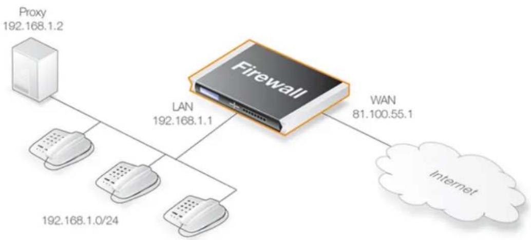
flowchart
graph TD
A["Proxy 192.168.1.2"] --> B["Firewall"]
C["192.168.1.0/24"] --> B
D["LAN 192.168.1.1"] --> B
E["WAN 81.100.55.1"] --> F["Internet"]
This scenario can be implemented in two ways:
• Using NAT to hide the network topology.
• Without NAT so the network topology is exposed.
Solution A - Using NAT
Here, the proxy and the local clients are hidden behind the IP address of the D-Link firewall. The setup steps are as follows:
-
Define a single SIP ALG object using the options described above.
-
Define a Service object and associate it with the SIP ALG object. The service should have the following properties:
• Destination Port: 5060 (the default SIP signaling port)
- Type: TCP/UDP
- Protocol: SIP
- Define three IP rule set entries
- A NAT entry for outbound traffic from the local proxy and the clients on the internal network to the remote clients on, for example, the Internet. The SIP ALG will take care of all address translation needed by the NAT rule. This translation will occur both on the IP level and the application level. Neither the clients or the proxies need to be aware that the local clients are being NATed.
If Record-Route is enabled on the SIP proxy, the source network of the NAT rule can include only the SIP proxy, and not the local clients.
- A SAT entry for redirecting inbound SIP traffic to the private IPv4 address of the NATed local proxy. This rule will have core as the destination interface (in other words, NetDefendOS itself) since inbound traffic will be sent to the private IPv4 address of the SIP proxy.
| SIP Traffic Type | Action | Src Interface | Src Network | Dest Interface | Dest Network |
| OutboundFrom ProxyUsers | Allow/NAT | Ian | lannet (ip_proxy) | wan | all-nets |
| InboundTo ProxyAndClients | Allow/SAT Dest IP: ip_proxy | wan | all-nets | core | wan_ip |
If Record-Route is enabled then the Source Network for outbound traffic from proxy users can be further restricted in the above by using "ip_proxy" as indicated.
When an incoming call is received, the SIP ALG will follow the SAT rule and forward the SIP request to the proxy server. The proxy will in turn, forward the request to its final destination which is the client.
If Record-Route is disabled at the proxy server, and depending on the state of the SIP session, the SIP ALG may forward inbound SIP messages directly to the client, bypassing the SIP proxy. This will happen automatically without further configuration.
Solution B - Without NAT
Without NAT, the outbound NAT IP rule set entry is replaced by an Allow entry. The inbound SAT and Allow IP rule set entries are replaced by a single Allow entry.
| Action | Src Interface | Src Network | Dest Interface | Dest Network | |
| OutboundFrom Proxy&Clients | Allow | lan | lannet(ip_proxy) | wan | all-nets |
| InboundTo Proxy&Clients | Allow | wan | all-nets | lan | lannet(ip_proxy) |
If Record-Route is enabled then the networks in the above can be further restricted by using "(ip_proxy)", as indicated.
Scenario 3
Protecting proxy and local clients - Proxy on the DMZ interface
This scenario is similar to the previous but the major difference is the location of the local SIP proxy server. The server is placed on a separate interface and network to the local clients. This setup adds an extra layer of security since the initial SIP traffic is never exchanged directly between a remote endpoint and the local, protected clients.
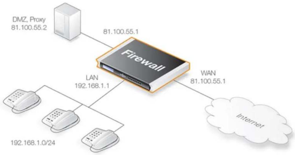
flowchart
graph TD
A["DMZ, Proxy 81.100.55.2"] --> B["Firewall"]
C["LAN 192.168.1.1"] --> B
D["Internet 192.168.1.0/24"] --> B
E["WAN 81.100.55.1"] --> B
The complexity is increased in this scenario since SIP messages flow across three interfaces: the receiving interface from the call initiator, the DMZ interface towards the proxy and the destination interface towards the call terminator. The initial messages exchanges that take place when a call is setup in this scenario are illustrated below:
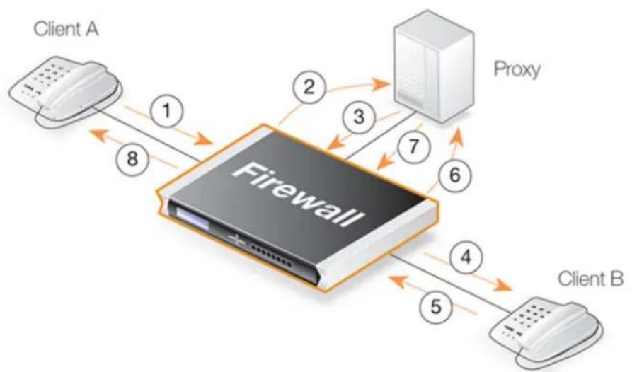
flowchart
graph LR
ClientA["Client A"] -->|1| Firewall["Firewall"]
Firewall -->|2| Proxy["Proxy"]
Firewall -->|3| Proxy
Firewall -->|4| ClientB["Client B"]
Firewall -->|5| ClientB
Firewall -->|6| Proxy
Firewall -->|7| Proxy
Firewall -->|8| ClientA
The exchanges illustrated in the above diagram are as follows:
• 1,2 - An initial INVITE is sent to the outbound local proxy server on the DMZ.
• 3,4 - The proxy server sends the SIP messages towards the destination on the Internet.
• 5,6 - A remote client or proxy server replies to the local proxy server.
• 7,8 - The local proxy forwards the reply to the local client.
This scenario can be implemented in a topology hiding setup with DMZ (Solution A below) as well as a setup without NAT (Solution B below).
Solution A - Using NAT
The following should be noted about this setup:
- The IP address of the SIP proxy must be a globally routable IP address. NetDefendOS does not support hiding of the proxy on the DMZ.
- The IP address of the DMZ interface must be a globally routable IP address. This address can be the same address as the one used on the external interface.
The setup steps are as follows:
- Define a single SIP ALG object using the options described above.
- Define a Service object and associate it with the SIP ALG object. The service should have the following properties:
• Destination Port: 5060 (the default SIP signaling port)
- Type: TCP/UDP
- Protocol: SIP
- Define four IP rule set entries:
- A NAT entry for outbound traffic from the clients on the internal network to the proxy located on the DMZ interface. The SIP ALG will take care of all address translation needed by the NAT rule. This translation will occur both at the IP level and at the application level.

Note
Clients registering with the proxy on the DMZ will have the IP address of the DMZ interface as the contact address.
- An Allow entry for outbound traffic from the proxy behind the DMZ interface to the remote clients on the Internet.
- An Allow IP rule set entry for inbound SIP traffic from the SIP proxy behind the DMZ interface to the IP address of the firewall. This will have core (in other words, NetDefendOS itself) as the destination interface.
The reason for this is because of the NAT rule set entry above. When an incoming call is received, NetDefendOS automatically locates the local receiver, performs address translation and forwards SIP messages to the receiver. This is done based on the SIP ALG's internal state.
- An Allow IP rule set entry for inbound traffic from, for example the Internet, to the proxy behind the DMZ.
- If Record-Route is not enabled at the proxy, direct exchange of SIP messages must also be
allowed between clients, bypassing the proxy. The following additional IP rule set entries are therefore needed when Record-Route is disabled:
- A NAT entry for outbound traffic from the clients on the internal network to the external clients and proxies on, for example, the Internet. The SIP ALG will take care of all address translation needed by the NAT entry. The translation will occur both at the IP level and the application level.
- An Allow rule set entry for inbound SIP traffic from, for example the Internet, to the IP address of the DMZ interface. The reason for this is because local clients will be NATed using the IP address of the DMZ interface when they register with the proxy located on the DMZ.
This IP rule set entry has core as the destination interface (in other words, NetDefendOS itself). When an incoming call is received, NetDefendOS uses the registration information of the local receiver to automatically locate this receiver, perform address translation and forward SIP messages to the receiver. This will be done based on the internal state of the SIP ALG.
The IP rule set entries needed with Record-Route enabled are:
| Action | Src Interface | Src Network | Dest Interface | Dest Network | |
| OutboundToProxy | Allow/NAT | lan | lannet | dmz | ip_proxy |
| OutboundFromProxy | Allow | dmz | ip_proxy | wan | all-nets |
| InboundFromProxy | Allow | dmz | ip_proxy | core | dmz_ip |
| InboundToProxy | Allow | wan | all-nets | dmz | ip_proxy |
With Record-Route disabled, the following IP rule set entries must be added to those given above:
| Action | Src Interface | Src Network | Dest Interface | Dest Network | |
| OutboundBypassProxy | Allow/NAT | lan | lannet | wan | all-nets |
| InboundBypassProxy | Allow | wan | all-nets | core | ipdmz |
Solution B - Without NAT
The setup steps are as follows:
-
Define a single SIP ALG object using the options described above.
-
Define a Service object which is associated with the SIP ALG object. The service should have the following properties:
-
Destination Port: 5060 (the default SIP signaling port)
- Type: TCP/UDP
-
Protocol: SIP
-
Define the following IP rule set entries:
-
An Allow IP rule set entry for outbound traffic from the clients on the internal network to the proxy located on the DMZ interface.
- An Allow IP rule set entry for outbound traffic from the proxy behind the DMZ interface to the remote clients on the Internet.
- An Allow IP rule set entry for inbound SIP traffic from the SIP proxy behind the DMZ interface to the clients located on the local, protected network.
- An Allow IP rule set entry for inbound SIP traffic from clients and proxies on the Internet to the proxy behind the DMZ interface.
- If Record-Route is not enabled at the proxy, direct exchange of SIP messages must also be allowed between clients, bypassing the proxy. The following two additional rules are therefore needed when Record-Route is disabled:
- An Allow IP rule set entry for outbound traffic from the clients on the local network to the external clients and proxies on the Internet.
- An Allow IP rule set entry for inbound SIP traffic from the Internet to clients on the local network.
The IP rule set entries with Record-Route enabled are as shown below:
| Action | Src Interface | Src Network | Dest Interface | Dest Network | |
| OutboundToProxy Allow lan lannet dmz ip_proxy | |||||
| OutboundFromProxy | Allow dmz ip_proxy | lan lannet | |||
| InboundFromProxy | Allow dmz ip_proxy | core dmz_ip | |||
| InboundToProxy | Allow | wan | all-nets | dmz | ip_proxy |
With Record-Route disabled, the following IP rule set entries must be added to those above:
| Action | Src Interface | Src Network | Dest Interface | Dest Network | |
| OutboundBypassProxy | Allow lan lannet wan | all-nets | |||
| InboundBypassProxy | Allow | wan | all-nets | lan | lannet |
SIP ALG Setup Using IP Rules
This section repeats the examples given previously but uses IP rules instead of IP policies to deploy the SIP ALG.
When configuring NetDefendOS for SIP sessions using IP rules, the following steps are required:
- Define a new SIP ALG object. Configurations upgraded from a version prior to NetDefendOS 11.03.00 may have a predefined SIP ALG object that could be used instead but creating a custom service is recommended.
- Define a single Service object for SIP communication and associate it with the ALG.
- Define the appropriate IP Rule or IP Policy objects for SIP communications which uses the defined Service object.
Example 6.17. SIP with Local Clients/Internet Proxy Using IP Rules
This example repeats Example 6.16, "SIP with Local Clients/Internet Proxy Using IP Policies" but uses IP rules instead of IP policies.
Web Interface
A. Define the following IP objects:
- if1_net: 192.168.1.0/24 (the internal network)
- proxy_ip: 81.100.55.2 (the SIP proxy)
- ip_wan: 81.100.55.1 (the firewall's public IPv4 address)
B. Define an SIP ALG object
-
Go to: Objects > ALG > Add > SIP ALG
-
Specify a name for the ALG, in this case my_sip_alg
-
Click OK
C. Define a custom Service object for SIP:
- Go to: Objects > Services > Add > TCP/UDP
- Specify a name for the service, in this case my_sip_service
- Choose UDP as the Type
- Choose my_sip_alg as the ALG
- For the Destination property, enter the port number 5060
- Click OK
D. Define the IP rule for outgoing SIP traffic:
-
Go to: Rules > IP Rule Set > main > Add > IP Rule
-
Now enter:
-
Name: sip_nat
• Action: NAT - Source Interface: if1
- Source Network: if1_net
- Destination Interface: ext
-
Destination Network: proxy_ip
• Service: my_sip_service
• Comment: Allow outgoing SIP calls -
Click OK
E. Define the IP Rule for incoming SIP traffic:
-
Go to: Rules > IP Rule Set > main > Add > IP Rule
-
Now enter:
-
Name: sip_allow
- Action: Allow
- Source Interface: ext
- Source Network: proxy_ip
- Destination Interface: core
-
Destination Network: ip_wan
• Service: my_sip_service
• Comment: Allow incoming SIP traffic -
Click OK
6.1.10. H.323 ALG
Overview
H.323 is a standard approved by the International Telecommunication Union (ITU) to allow compatibility in video conference transmissions over IP networks. It is used for real-time audio, video and data communication over packet-based networks such as the Internet. It specifies the components, protocols and procedures for providing such multimedia communication, including Internet phone and voice-over-IP (VoIP).
H.323 Components
H.323 consists of four main components:
Terminals Devices used for audio and optionally video or data communication, such as phones, conferencing units, or "software phones" such as the product "NetMeeting".
Gateways An H.323 gateway connects two dissimilar networks and translates traffic between them. It provides connectivity between H.323 networks and non-H.323 networks such as public switched telephone networks (PSTN), translating protocols and converting media streams. A gateway is not required for communication between two H.323 terminals.
Gatekeepers
The Gatekeeper is a component in the H.323 system which is used for addressing, authorization and authentication of terminals and gateways. It can also take care of bandwidth management, accounting, billing and charging. The gatekeeper may allow calls to be placed directly between
| endpoints, or it may route the call signaling through itself to perform functions such as follow-me/find-me, forward on busy, etc. It is needed when there is more than one H.323 terminal behind a NATing device with only one public IP. | |
| Multipoint Control Units | MCUs provide support for conferences of three or more H.323 terminals. All H.323 terminals participating in the conference call have to establish a connection with the MCU. The MCU then manages the calls, resources, video and audio codecs used in the call. |
H.323 Protocols
The different protocols used in implementing H.323 are:
H.225 RAS signaling and Call Control (Setup) signaling
Used for call signaling. It is used to establish a connection between two H.323 endpoints. This call signal channel is opened between two H.323 endpoints or between a H.323 endpoint and a gatekeeper. For communication between two H.323 endpoints, TCP 1720 is used. When connecting to a gatekeeper, UDP port 1719 (H.225 RAS messages) are used.
H.245 Media Control and Transport
Provides control of multimedia sessions established between two H.323 endpoints. Its most important task is to negotiate opening and closing of logical channels. A logical channel could be, for example, an audio channel used for voice communication. Video and T.120 channels are also called logical channels during negotiation.
T.120 A suite of communication and application protocols.
Depending on the type of H.323 product, T.120 protocol can be used for application sharing, file transfer as well as for conferencing features such as whiteboards.
H.323 ALG features
The H.323 ALG is a flexible application layer gateway that allows H.323 devices such as H.323 phones and applications to make and receive calls between each other when connected via private networks secured by D-Link firewalls.
The H.323 specification was not designed to handle NAT, as IP addresses and ports are sent in the payload of H.323 messages. The H.323 ALG modifies and translates H.323 messages to make sure that H.323 messages will be routed to the correct destination and allowed through the firewall.
H.323 handling by NetDefendOS has the following characteristics:
- NetDefendOS supports version H.323 version 5 of the H.323 specification. This specification is built upon H.225.0 v5 and H.245 v10.
- In addition to support voice and video calls, NetDefendOS supports application sharing over the T.120 protocol. T.120 uses TCP to transport data while voice and video is transported over UDP.
- To support gatekeepers, NetDefendOS monitors RAS traffic between H.323 endpoints and the gatekeeper, in order to correctly configure the D-Link firewall to let calls through.
- NAT and SAT IP rule set entries are supported, allowing clients and gatekeepers to use private IPv4 addresses on a network behind the firewall.
Methods of Setting up the H.323 ALG
Deploying the H.323 ALG can be done using one of the following methods:
• Using a VoIP Profile object with an IP Policy object
The H.323 ALG can be configured using IP Policy objects and this is the recommended method. Setup is done by creating a VoIP Profile object and specifying the H.323 options on that. The VoIP Profile object is then associated with an IP Policy object that triggers on the target traffic.
A Service object configured for H.323 traffic must also be used with the IP Policy object. This Service object must have its Protocol property set to H.323.
The predefined H.323 service objects in the default configuration for NetDefendOS 11.03 and later already have their Protocol property set to be H.323. This will not be true where NetDefendOS has been upgraded to version 11.03 or later.
• Using an H.323 ALG object with an IP Rule object
Alternatively, an H.323 ALG object can be associated with a Service object configured for the H.323 protocol. The service object is then used with the IP Rule objects that control H.323 traffic flow.
In NetDefendOS version 11.03 and later, a predefined H.323 ALG is not present in the default configuration and therefore a new H.323 ALG object must always be created when using an IP Rule object with H.323. In older NetDefendOS versions that are upgraded to 11.03 or later, the predefined H.323 ALG object will be retained.
H.323 ALG Options
When using IP policies, the following H.323 ALG properties can be configured on an associated VoIP Profile to control how the ALG behaves:
- Allow TCP Data Channels
This option allows TCP based data channels to be negotiated. Data channels are used, for example, by the T.120 protocol.
• Max TCP Data Channels
The maximum number of TCP data channels can be specified.
• Max Gatekeeper Registration Lifetime
The gatekeeper registration lifetime can be controlled in order to force re-registration by clients within a certain time. A shorter time forces more frequent registration by clients with the gatekeeper and less probability of a problem if the network becomes unavailable and the client thinks it is still registered.
- Translate Addresses
The default value for address translation is Automatic. If set to Specific, a particular network and IP address can be set. If not enabled then no address translation will be done on logical channel addresses and the administrator needs to be sure about IP addresses and routes
used in a particular scenario.
• Network and IP Address
This option is available if the Translate Address option is set to Specific. For NATed traffic, the Network specifies what is allowed to be translated. The IP Address specifies which IPv4 address to NAT with. If Translate Addresses is to Automatic, the external IP address is found automatically through route lookup.
- Channel setup mode
This can either be set to Optimistic (the default) or Normal. The Optimistic setting means that the logical H.323 channel is opened when only a single direction is established. The Normal setting means that a bidirectional connection must be established before the logical channel is opened.
If using IP rules instead of properties, the above properties are available directly on the H.323 ALG object.
H.323 Service Object Setup
When creating IP rule set entries that target H.323, a Service object is required that targets the protocol. The properties of the Service object created for H.323 should be as follows:
• H.323 Service - Type: TCP, Destination port: 1720
• H.323 Gatekeeper Service - Type: UDP, Destination port: 1719
When using IP Policy objects, the Protocol property of the associated service must be set to H.323 for the H.323 ALG to become available for activation.
There are predefined Service objects in NetDefendOS which are called h323 and h323-gatekeeper and these could be used instead of the custom Service objects used in the examples. However, if using these objects with an IP Policy, it should be checked that the Protocol property of the Service is set to H.323. This is automatically true for the default configuration of NetDefendOS 11.03 or later but not true for upgrades from versions prior to 11.03.
H.323 ALG Setup Examples Using IP Policies
The following examples illustrate how to set up the H.323 ALG using IP Policy objects in the IP rule set in various scenarios.
Example 6.18. Protecting Internal H.323 Phones Using IP Policies
In this example, an internal H.323 phone is situated on Iannet and has a public IP address. To make it possible to place a call from this phone to another H.323 phone on the Internet and to allow H.323 phones on the Internet to call this phone, IP rule set entries need to be added.
Note: Make sure there are no other IP rule set entries disallowing or allowing the same kind of ports/traffic before the entries in this example.
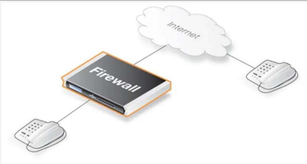
flowchart
graph TD
A["Firewall"] --> B["Internet"]
A --> C["Client Device 1"]
A --> D["Client Device 2"]
Note that the Service object used must have its Protocol property set to be H.323.
Web Interface
Create a new VoIP Profile object:
- Go to: Policies > Firewalling > VoIP > Add > VoIP Profile
-
Now enter:
-
Name: my_h323_profile
-
SIP: Disable
-
Click OK
Create a custom Service object for H.323:
- Go to: Objects > Services > Add > TCP/UDP
-
Now enter:
-
Name: my_h323_service
- Type: TCP
- Destination port: 1720
-
Protocol: H.323
-
Click OK
Create an IP policy for outgoing H.323 traffic:
- Go to: Policies > Firewalling > Main IP Rules > Add > IP Policy
- Now enter:
- Name: h323_allow_out
• Action: Allow
-
Under Filter enter:
-
Source Interface: Ian
- Source Network: Iannet
- Destination Interface: any
-
Destination Network: all-nets
• Service: my_h323_service
• Comment: Allow outgoing H.323 calls. -
Under Source Translation enter:
- Address Translation: None
-
Under VoIP enter:
-
Enable VoIP: ON
• VoIP Profile: my_h323_profile -
Click OK
Create an IP policy for incoming H.323 traffic:
- Go to: Policies > Firewalling > Main IP Rules > Add > IP Policy
-
Now enter:
-
Name: h323_allow_in
-
Action: Allow
-
Under Filter enter:
-
Source Interface: any
• Source Network: all-nets - Destination Interface: Ian
-
Destination Network: Iannet
• Service: my_h323_policy_service
• Comment: Allow incoming H.323 calls. -
Under Source Translation enter:
- Address Translation: None
- Under VoIP enter:
- Enable VoIP: ON
- VoIP Profile: my_h323_profile
- Click OK
Example 6.19. H.323 with a Private Address Using IP Policies
In this example, an internal H.323 phone is on a network with private IPv4 addresses. To make a call from this phone to another H.323 phone on the Internet and to allow H.323 phones on the Internet to call this phone, IP rule set entries need to be added.
Note: Make sure there are no IP rule set entries disallowing or allowing the same kind of traffic before these entries.
When using private IPs on the phone, incoming traffic needs to be SATed, as in the example below. The IPv4 address object ip-phone is the internal IP of the H.323 phone.
Web Interface
Create a new VoIP Profile object:
-
Go to: Policies > Firewalling > VoIP > Add > VoIP Profile
-
Now enter:
-
Name: my_h323_profile
-
SIP: Disable
-
Click OK
Create a custom Service object for H.323:
- Go to: Objects > Services > Add > TCP/UDP
-
Now enter:
-
Name: my_h323_service
- Type: TCP
- Destination port: 1720
-
Protocol: H.323
-
Click OK
Create the outgoing IP policy:
- Go to: Policies > Firewalling > Main IP Rules > Add > IP Policy
- Now enter:
- Name: h323_nat_out
• Action: Allow
-
Under Filter enter:
-
Source Interface: Ian
- Source Network: Iannet
- Destination Interface: any
-
Destination Network: all-nets
• Service: my_h323_service
• Comment: Allow outgoing H.323 calls. -
Under Source Translation enter:
-
Address Translation: NAT
• Address Action: Outgoing Interface IP -
Under VoIP enter:
-
Enable VoIP: ON
• VoIP Profile: my_h323_profile -
Click OK
Create the SAT IP policy for incoming H.323 traffic:
- Go to: Policies > Firewalling > Main IP Rules > Add > IP Policy
-
Now enter:
-
Name: h323_sat_in
• Action: Allow -
Under Filter enter:
-
Source Interface: any
• Source Network: all-nets -
Destination Interface: core
-
Destination Network: wan_ip (external IP of the firewall)
• Service: my_h323_service
• Comment: Allow incoming calls to H.323 phones via ip-phone. -
Under Source Translation enter:
- Address Translation: None
-
Under Destination Translation enter:
-
Address Translation: SAT
• Address Action: Single IP -
New IP Address: ip-phone
-
Under VoIP enter:
-
Enable VoIP: ON
• VoIP Profile: my_h323_profile -
Click OK
To place a call to the phone behind the D-Link firewall, place a call to the external IP address on the firewall. If multiple H.323 phones are placed behind the firewall, one SAT IP rule set entry has to be configured for each phone. This means that multiple external addresses have to be used. However, it is better to use a H.323 gatekeeper as this only requires one external address.
Example 6.20. Two Phones Behind Different Clavister Firewalls Using IP Policies
This scenario consists of two H.323 phones, each one connected behind the D-Link firewall on a network with public IPv4 addresses. In order to place calls on these phones over the Internet, entries need to be added to the IP rule sets of both firewalls. Make sure there are no IP rule set entries disallowing or allowing the same kind of ports/traffic before these entries.
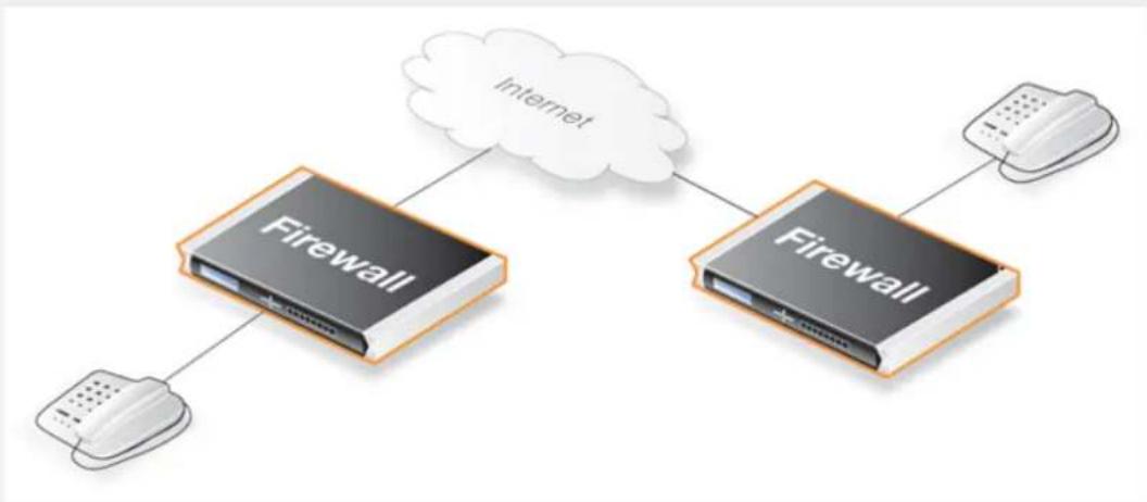
flowchart
graph TD
A["Firewall"] --> B["Internet"]
C["Firewall"] --> D["Router"]
E["Router"] --> F["Router"]
style A fill:#f9f,stroke:#333
style C fill:#f9f,stroke:#333
style E fill:#f9f,stroke:#333
style B fill:#ccf,stroke:#333
style D fill:#ccf,stroke:#333
style F fill:#ccf,stroke:#333
Web Interface
Create a new VoIP Profile object:
-
Go to: Policies > Firewalling > VoIP > Add > VoIP Profile
-
Now enter:
-
Name: my_h323_profile
- SIP: Disable
3. Click OK
Create a custom Service object for H.323:
-
Go to: Objects > Services > Add > TCP/UDP
-
Now enter:
-
Name: my_h323_service
- Type: TCP
- Destination port: 1720
-
Protocol: H.323
-
Under VoIP enter:
-
Enable VoIP: ON
• VoIP Profile: my_h323_profile -
Click OK
Create an IP policy for outgoing traffic:
- Go to: Policies > Firewalling > Main IP Rules > Add > IP Policy
-
Now enter:
-
Name: h323_allow_out
-
Action: Allow
-
Under Filter enter:
-
Source Interface: Ian
• Source Network: Iannet - Destination Interface: any
-
Destination Network: all-nets
• Service: my_h323_service
• Comment: Allow outgoing H.323 calls. -
Under Source Translation enter:
- Address Translation: None
-
Under VoIP enter:
-
Enable VoIP: ON
• VoIP Profile: my_h323_profile -
Click OK
Create the IP policy for incoming traffic:
-
Go to: Policies > Firewalling > Main IP Rules > Add > IP Policy
-
Now enter:
-
Name: h323_allow_in
-
Action: Allow
-
Under Filter enter:
-
Source Interface: any
- Source Network: all-nets
- Destination Interface: Ian
-
Destination Network: Iannet
• Service: my_h323_service
• Comment: Allow incoming H.323 calls. -
Under Source Translation enter:
- Address Translation: None
-
Under VoIP enter:
-
Enable VoIP: ON
• VoIP Profile: my_h323_profile -
Click OK
Example 6.21. Using Private IPv4 Addresses with IP Policies
This scenario consists of two H.323 phones, each one connected behind the D-Link firewall on a network with private IPv4 addresses. In order to place calls on these phones over the Internet, entries need to be added to the IP rule set in the firewall. Make sure there are no rule set entries disallowing or allowing the same kind of ports/traffic before these entries.
As we are using private IPs on the phones, incoming traffic need to be SATed as in the example below. The object ip-phone should be the internal IP of the H.323 phone behind each firewall.
Web Interface
Create a new VoIP Profile object:
-
Go to: Policies > Firewalling > VoIP > Add > VoIP Profile
-
Now enter:
- Name: my_h323_profile
- SIP: Disable
3. Click OK
Create a custom Service object for H.323:
-
Go to: Objects > Services > Add > TCP/UDP
-
Now enter:
-
Name: my_h323_service
- Type: TCP
- Destination port: 1720
- Protocol: H.323
3. Click OK
Create the outgoing traffic NAT IP policy:
- Go to: Policies > Firewalling > Main IP Rules > Add > IP Policy
-
Now enter:
-
Name: h323_nat_out
-
Action: Allow
-
Under Filter enter:
-
Source Interface: Ian
- Source Network: Iannet
- Destination Interface: any
-
Destination Network: all-nets
• Service: my_h323_service
• Comment: Allow outgoing H.323 calls. -
Under Source Translation enter:
-
Address Translation: NAT
• Address Action: Outgoing Interface IP -
Under VoIP enter:
-
Enable VoIP: ON
• VoIP Profile: my_h323_profile
6. Click OK
Create the SAT IP policy for incoming traffic:
-
Go to: Policies > Firewalling > Main IP Rules > Add > IP Policy
-
Now enter:
-
Name: h323_sat_in
-
Action: Allow
-
Under Filter enter:
-
Source Interface: any
- Source Network: all-nets
- Destination Interface: core
-
Destination Network: wan_ip (external IP of the firewall)
• Service: my_h323_service
• Comment: Allow incoming calls to H.323 phone at ip-phone. -
Under Source Translation enter:
- Address Translation: None
-
Under Destination Translation enter:
-
Address Translation: SAT
• Address Action: Single IP -
New IP Address: ip-phone
-
Under VoIP enter:
-
Enable VoIP: ON
• VoIP Profile: my_h323_profile -
Click OK
To place a call to the phone behind the firewall, place a call to the external IP address of the firewall. If multiple H.323 phones are placed behind the firewall, one SAT IP rule set entry has to be configured for each phone. This means that multiple external addresses have to be used. It is better to use an H.323 gatekeeper as this only requires one external address.
Example 6.22. H.323 with Gatekeeper Using IP Policies
In this scenario, a H.323 gatekeeper is placed in the DMZ connected to the firewall. An IP policy is configured in the firewall to allow traffic between the private network where the H.323 phones are connected on the internal network and to the gAtekeeper on the DMZ. The gatekeeper on the DMZ is configured with a private address.
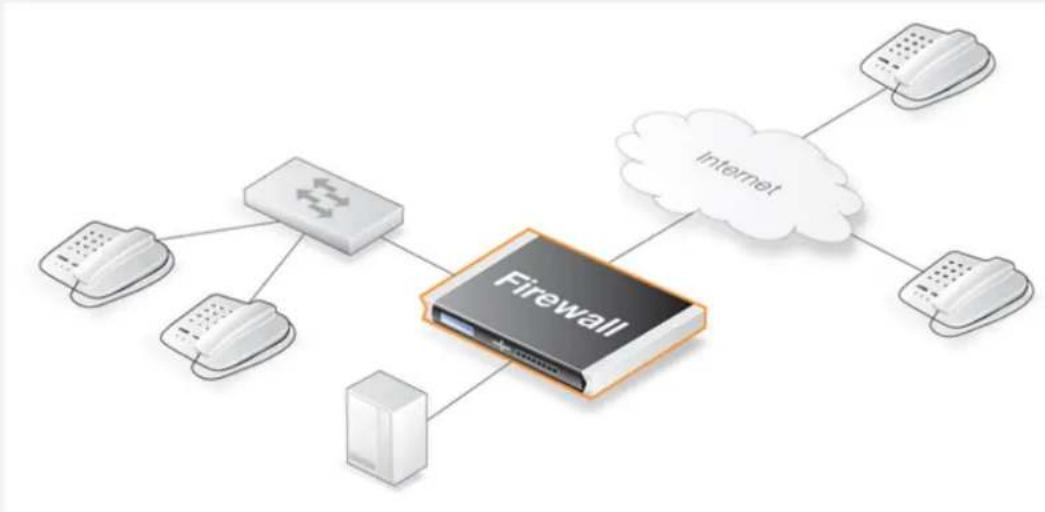
flowchart
graph TD
A["Phone"] --> B["Router"]
C["Phone"] --> B
D["Phone"] --> B
E["Phone"] --> B
F["Phone"] --> G["Firewall"]
H["Cloud"] --> I["Internet"]
I --> J["Phone"]
Web Interface
Create a new VoIP Profile object:
- Go to: Policies > Firewalling > VoIP > Add > VoIP Profile
-
Now enter:
-
Name: my_h323_profile
-
SIP: Disable
-
Click OK
Create a custom Service object for the H.323 gatekeeper:
- Go to: Objects > Services > Add > TCP/UDP
-
Now enter:
-
Name: my_h323_gatekeeper_service
- Type: UDP
- Destination port: 1719
-
Protocol: H.323
-
Click OK
Create the SAT IP policy for incoming gatekeeper traffic:
- Go to: Policies > Firewalling > Main IP Rules > Add > IP Policy
-
Now enter:
-
Name: h323_sat_gk_in
-
Action: Allow
-
Under Filter enter:
-
Source Interface: any
• Source Network: all-nets - Destination Interface: core
- Destination Network: wan_ip (external IP of the firewall)
• Service: my_h323_gatekeeper_service -
Comment: SAT rule for incoming communication with the gatekeeper located at ip-gatekeeper.
-
Under Source Translation enter:
- Address Translation: None
-
Under Destination Translation enter:
-
Address Translation: SAT
• Address Action: Single IP
• New IP Address: ip-gatekeeper -
Under VoIP enter:
-
Enable VoIP: ON
• VoIP Profile: my_h323_profile -
Click OK
Create the IP policy that allows traffic from lannet to the gatekeeper:
- Go to: Policies > Firewalling > Main IP Rules > Add > IP Policy
-
Now enter:
-
Name: h323_gk_in
-
Action: Allow
-
Under Filter enter:
-
Source Interface: Ian
- Source Network: Iannet
- Destination Interface: dmz
-
Destination Network: ip-gatekeeper (IP address of the gatekeeper)
• Service: my_h323_gatekeeper_service
• Comment: Allow incoming communication with the gatekeeper. -
Under Source Translation enter:
- Address Translation: None
-
Under VoIP enter:
-
Enable VoIP: ON
• VoIP Profile: my_h323_profile -
Click OK

Note: Outgoing calls do not need a specific IP policy
There is no need to specify a specific IP rule set entry for outgoing calls. NetDefendOS monitors the communication between "external" phones and the Gatekeeper to make sure that it is possible for internal phones to call the external phones that are registered with the gatekeeper.
Example 6.23. H.323 with Gatekeeper and two D-Link firewalls
This scenario is quite similar to the previous example, with the difference that the D-Link firewall is protecting the "external" phones. The firewall with the gatekeeper connected to the DMZ should be configured exactly as in the previous example. The other firewall should be configured as below. IP rule set entries need to be added and there should not be other entries disallowing or allowing the same kind of ports/traffic before these entries.
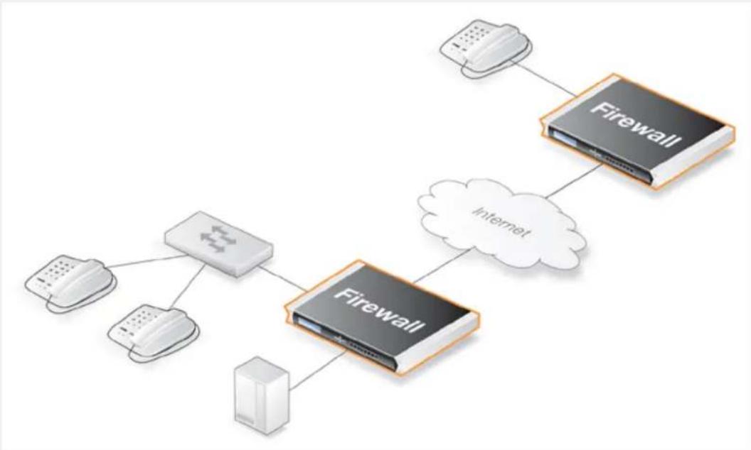
flowchart
graph TD
A["Firewall"] --> B["Internet"]
C["Firewall"] --> D["Firewall"]
E["Firewall"] --> F["Firewall"]
G["Firewall"] --> H["Firewall"]
I["Firewall"] --> J["Firewall"]
K["Firewall"] --> L["Firewall"]
M["Firewall"] --> N["Firewall"]
O["Firewall"] --> P["Firewall"]
Q["Firewall"] --> R["Firewall"]
S["Firewall"] --> T["Firewall"]
Web Interface
Create a new VoIP Profile object:
-
Go to: Policies > Firewalling > VoIP > Add > VoIP Profile
-
Now enter:
-
Name: my_h323_profile
-
SIP: Disable
-
Click OK
Create a custom Service object for the H.323 gatekeeper:
-
Go to: Objects > Services > Add > TCP/UDP
-
Now enter:
-
Name: my_h323_gatekeeper_service
- Type: UDP
• Destination port: 1719 -
Protocol: H.323
-
Click OK
Create an NAT IP policy for outgoing gatekeeper traffic from Iannet to the Internet:
-
Go to: Policies > Firewalling > Main IP Rules > Add > IP Policy
-
Now enter:
-
Name: h323_nat_out
-
Action: Allow
-
Under Filter enter:
-
Source Interface: Ian
• Source Network: Iannet - Destination Interface: any
-
Destination Network: all-nets
• Service: my_h323_gatekeeper_service
• Comment: Allow outgoing communication from the gatekeeper. -
Under Source Translation enter:
-
Address Translation: NAT
• Address Action: Outgoing Interface IP -
Under VoIP enter:
-
Enable VoIP: ON
• VoIP Profile: my_h323_profile
6. Click OK

Note: Outgoing calls do not need a specific IP policy
There is no need to specify a specific IP policy for outgoing calls. NetDefendOS monitors the communication between "external" phones and the Gatekeeper to make sure that it is possible for internal phones to call the external phones that are registered with the gatekeeper.
Example 6.24. Using H.323 in an Enterprise Environment
This is an example of a more complex situation that shows how the H.323 ALG can be deployed in a enterprise environment. At the head office DMZ is a H.323 gatekeeper that can handle all H.323 clients in the head, branch and remote offices. This will allow the whole enterprise to use the network for both voice communication and application sharing.
It is assumed that the VPN tunnels are correctly configured and that all offices use private IP ranges on their local networks. All outside calls are made over the existing telephone network using the gateway (ip-gateway) which is connected to the ordinary telephone network.
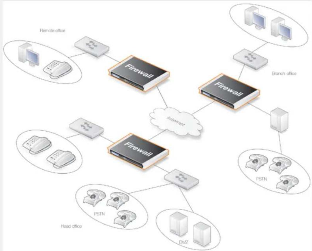
flowchart
graph TD
A["Remote office"] --> B["Firewall"]
C["Branch office"] --> D["Firewall"]
B --> E["Internet"]
D --> E
F["Head office"] --> G["PSTN"]
F --> H["DVZ"]
G --> I["Firewall"]
H --> I
style A fill:#f9f,stroke:#333
style C fill:#f9f,stroke:#333
style F fill:#ccf,stroke:#333
style G fill:#cfc,stroke:#333
style H fill:#fcc,stroke:#333
style I fill:#cff,stroke:#333
The head office has placed a H.323 Gatekeeper in the DMZ of the corporate D-Link firewall. This firewall should be configured as follows:
Web Interface
Create a new VoIP Profile object:
-
Go to: Policies > Firewalling > VoIP > Add > VoIP Profile
-
Now enter:
-
Name: my_h323_profile
-
SIP: Disable
-
Click OK
Create a custom Service object for the H.323 gatekeeper:
-
Go to: Objects > Services > Add > TCP/UDP
-
Now enter:
-
Name: my_h323_gatekeeper_service
- Type: UDP
- Destination port: 1719
-
Protocol: H.323
-
Click OK
Create an IP policy for traffic from lannet to gatekeeper:
-
Go to: Policies > Firewalling > Main IP Rules > Add > IP Policy
-
Now enter:
-
Name: lan_to_gk
-
Action: Allow
-
Under Filter enter:
-
Source Interface: Ian
• Source Network: Iannet - Destination Interface: dmz
-
Destination Network: ip-gatekeeper
• Service: my_h323_gatekeeper_service
• Comment: Allow H.323 entities on lannet to connect to the gatekeeper. -
Under Source Translation enter:
- Address Translation: None
-
Under VoIP enter:
-
Enable VoIP: ON
• VoIP Profile: my_h323_profile
6. Click OK
Create an IP policy for traffic from the gateway to internal phones on lannet:
-
Go to: Policies > Firewalling > Main IP Rules > Add > IP Policy
-
Now enter:
-
Name: gw_to_lan
-
Action: Allow
-
Under Filter enter:
-
Source Interface: dmz
- Source Network: ip-gateway
- Destination Interface: Ian
- Destination Network: Iannet
• Service: my_h323_gatekeeper_service
• Comment: Allow communication from the gateway to H.323 phones on Iannet.
- Under Source Translation enter:
- Address Translation: None
-
Under VoIP enter:
-
Enable VoIP: ON
• VoIP Profile: my_h323_profile
6. Click OK
Create an IP policy for traffic from the gateway to internal phones on lannet:
-
Go to: Policies > Firewalling > Main IP Rules > Add > IP Policy
-
Now enter:
-
Name: branch_to_gw
• Action: Allow -
Under Filter enter:
-
Source Interface: vpn-branch
- Source Network: branch-net
- Destination Interface: dmz
• Destination Network: ip-gatekeeper, ip-gateway
• Service: my_h323_gatekeeper_service
- Comment: Allow communication with the gatekeeper on DMZ from the branch network.
- Under Source Translation enter:
- Address Translation: None
- Under VoIP enter:
- Enable VoIP: ON
• VoIP Profile: my_h323_profile
- Click OK
Create an IP policy for traffic from the VPN to the gatekeeper:
-
Go to: Policies > Firewalling > Main IP Rules > Add > IP Policy
-
Now enter:
- Name: vpn_to_gw
- Action: Allow
-
Under Filter enter:
-
Source Interface: vpn-remote
- Source Network: remote-net
- Destination Interface: dmz
- Destination Network: ip-gatekeeper
• Service: my_h323_gatekeeper_service -
Comment: Allow communication with the gatekeeper on DMZ from the remote network.
-
Under Source Translation enter:
- Address Translation: None
-
Under VoIP enter:
-
Enable VoIP: ON
• VoIP Profile: my_h323_profile -
Click OK
Example 6.25. Configuring remote offices for H.323
If the branch and remote office H.323 phones and applications are to be configured to use the H.323 gatekeeper at the head office, the D-Link firewalls in the remote and branch offices should be configured as follows:
Here, the interface called vpn-hq is the VPN tunnel to the network hq-net located at headquarters.
Note: This IP policy should exist in both the branch and remote office NetDefendOS configurations.
Web Interface
-
Go to: Policies > Firewalling > Main IP Rules > Add > IP Policy
-
Now enter:
-
Name: to_gw
• Action: Allow -
Under Filter enter:
-
Source Interface: Ian
- Source Network: Iannet
- Destination Interface: vpn-hq
- Destination Network: hq-net
• Service: my_h323_gatekeeper_service -
Comment: Allow communication with the gatekeeper connected to the head office DMZ.
-
Under Source Translation enter:
- Address Translation: None
-
Under VoIP enter:
-
Enable VoIP: ON
• VoIP Profile: my_h323_profile -
Click OK
Example 6.26. Allowing the H.323 Gateway to register with the Gatekeeper
The branch office D-Link firewall has a H.323 gateway connected to its DMZ. In order to allow the H.323 gateway to register with the H.323 gatekeeper at the Head Office, the following has to be configured:
Web Interface
-
Go to: Policies > Firewalling > Main IP Rules > Add > IP Policy
-
Now enter:
-
Name: gw_to_gk
• Action: Allow -
Under Filter enter:
-
Source Interface: dmz
• Source Network: ip-branchgw - Destination Interface: vpn-hq
- Destination Network: hq-net
• Service: my_h323_gatekeeper_service -
Comment: Allow the gateway to communicate with the gatekeeper connected to the head office.
-
Under Source Translation enter:
- Address Translation: None
-
Under VoIP enter:
-
Enable VoIP: ON
• VoIP Profile: my_h323_profile -
Click OK

Note: Outgoing calls do not need a specific IP policy
There is no need to specify a specific IP rule set entry for outgoing calls. NetDefendOS monitors the communication between "external" phones and the gatekeeper to make sure that it is possible for internal phones to call the external phones that are registered with the gatekeeper.
H323 ALG Examples Using IP Rules
The following examples repeat the examples in this section but use IP Rule objects instead of IP Policy objects. Using IP policies is the recommended method for H323 ALG setup. These examples are included for completeness.
Example 6.27. Protecting Internal H.323 Phones Using IP Rules
This example repeats Example 6.18, "Protecting Internal H.323 Phones Using IP Policies" but uses IP
rules instead of IP policies.
Web Interface
Create a new H.323 ALG object:
-
Go to: Objects > ALG > Add > H.323 ALG
-
Specify a name for the ALG, in this case my_h323_alg
-
Click OK
Create a custom Service object for H.323:
-
Go to: Objects > Services > Add > TCP/UDP
-
Now enter:
-
Name: my_h323_service
- Type: TCP
- ALG: my_h323_alg
-
Destination port: 1720
-
Click OK
Create an IP rule for outgoing H.323 traffic:
-
Go to: Policies > Firewalling > Main IP Rules > Add > IP Rule
-
Now enter:
-
Name: H323AllowOut
- Action: Allow
- Source Interface: Ian
- Source Network: Iannet
- Destination Interface: any
-
Destination Network: all-nets
• Service: my_h323_service
• Comment: Allow outgoing H.323 calls. -
Click OK
Create an IP rule for incoming H.323 traffic:
-
Go to: Policies > Firewalling > Main IP Rules > Add > IP Rule
-
Now enter:
- Name: H323AllowIn
• Action: Allow
- Source Interface: any
• Source Network: all-nets
- Destination Interface: Ian
- Destination Network: Iannet
• Service: my_h323_service
• Comment: Allow incoming H.323 calls.
3. Click OK
Example 6.28. H.323 with a Private Address Using IP Rules
This example repeats Example 6.19, "H.323 with a Private Address Using IP Policies" but uses IP rules instead of IP policies.
Web Interface
Create a new H.323 ALG object:
- Go to: Objects > ALG > Add > H.323 ALG
- Specify a name for the ALG, in this case my_h323_alg
- Click OK
Create a custom Service object for H.323:
- Go to: Objects > Services > Add > TCP/UDP
- Now enter:
- Name: my_h323_service
- Type: TCP
- ALG: my_h323_alg
- Destination port: 1720
3. Click OK
Create the outgoing IP rule:
- Go to: Policies > Firewalling > Main IP Rules > Add > IP Rule
- Now enter:
- Name: H323Out
• Action: NAT
- Source Interface: Ian
- Source Network: Iannet
- Destination Interface: any
- Destination Network: all-nets
• Service: my_h323_service
• Comment: Allow outgoing H.323 calls.
3. Click OK
Create the SAT IP rules for incoming H.323 traffic:
-
Go to: Policies > Firewalling > Main IP Rules > Add > IP Rule
-
Now enter:
-
Name: H323In
• Action: SAT - Source Interface: any
- Source Network: all-nets
- Destination Interface: core
-
Destination Network: wan_ip (external IP of the firewall)
• Service: my_h323_service
• Comment: Allow incoming calls to H.323 phones via ip-phone. -
For SAT enter Translate Destination IP Address: To New IP Address: ip-phone (IP address of phone)
4. Click OK
-
Go to: Policies > Firewalling > Main IP Rules > Add > IP Rule
-
Now enter:
-
Name: H323In
- Action: Allow
- Source Interface: any
• Source Network: all-nets - Destination Interface: core
- Destination Network: wan_ip (external IP of the firewall)
• Service: my_h323_service
• Comment: Allow incoming calls to H.323 phones via ip-phone.
- Click OK
Example 6.29. Two Phones Behind Different Firewalls Using IP Rules
This example repeats Example 6.20, "Two Phones Behind Different Clavister Firewalls Using IP Policies" but uses IP rules instead of IP policies.
Web Interface
Create a new H.323 ALG object:
- Go to: Objects > ALG > Add > H.323 ALG
- Specify a name for the ALG, in this case my_h323_alg
- Click OK
Create a custom Service object for H.323:
- Go to: Objects > Services > Add > TCP/UDP
-
Now enter:
-
Name: my_h323_service
- Type: TCP
- ALG: my_h323_alg
-
Destination port: 1720
-
Click OK
Create the outgoing traffic IP rule:
- Go to: Policies > Firewalling > Main IP Rules > Add > IP Rule
-
Now enter:
-
Name: H323AllowOut
• Action: Allow - Source Interface: Ian
- Source Network: Iannet
- Destination Interface: any
- Destination Network: all-nets
• Service: my_h323_service
• Comment: Allow outgoing H.323 calls.
3. Click OK
Create the incoming traffic IP rule:
-
Go to: Policies > Firewalling > Main IP Rules > Add > IP Rule
-
Now enter:
-
Name: H323AllowIn
- Action: Allow
- Source Interface: any
• Source Network: all-nets - Destination Interface: Ian
- Destination Network: Iannet
• Service: my_h323_service
• Comment: Allow incoming H.323 calls.
3. Click OK
Example 6.30. Using Private IPv4 Addresses - IP Rules Version
This example repeats Example 6.21, "Using Private IPv4 Addresses with IP Policies" but uses IP rules instead of IP policies.
Web Interface
Create a new H.323 ALG object:
- Go to: Objects > ALG > Add > H.323 ALG
- Specify a name for the ALG, in this case my_h323_alg
- Click OK
Create a custom Service object for H.323:
- Go to: Objects > Services > Add > TCP/UDP
- Now enter:
- Name: my_h323_service
-
Type: TCP
-
ALG: my_h323_alg
- Destination port: 1720
3. Click OK
Create the outgoing traffic NAT IP rule:
-
Go to: Policies > Firewalling > Main IP Rules > Add > IP Rule
-
Now enter:
-
Name: H323Out
• Action: NAT - Source Interface: Ian
- Source Network: Iannet
- Destination Interface: any
- Destination Network: all-nets
• Service: my_h323_service
• Comment: Allow outgoing H.323 calls.
3. Click OK
Create the incoming traffic SAT IP rules:
-
Go to: Policies > Firewalling > Main IP Rules > Add > IP Rule
-
Now enter:
-
Name: H323In
• Action: SAT - Source Interface: any
• Source Network: all-nets - Destination Interface: core
-
Destination Network: wan_ip (external IP of the firewall)
• Service: my_h323_service
• Comment: Allow incoming calls to H.323 phone at ip-phone. -
For SAT enter Translate Destination IP Address: To New IP Address: ip-phone (IP address of phone)
-
Click OK
-
Go to: Policies > Firewalling > Main IP Rules > Add > IP Rule
2. Now enter:
- Name: H323In
• Action: Allow - Source Interface: any
- Source Network: all-nets
- Destination Interface: core
- Destination Network: wan_ip (external IP of the firewall)
• Service: my_h323_service
• Comment: Allow incoming calls to H.323 phone at ip-phone.
3. Click OK
Example 6.31. H.323 with Gatekeeper Using IP Rules
This example repeats Example 6.22, "H.323 with Gatekeeper Using IP Policies" but uses IP rules instead of IP policies.
Web Interface
Create a new H.323 ALG object:
- Go to: Objects > ALG > Add > H.323 ALG
- Specify a name for the ALG, in this case my_h323_alg
- Click OK
Create a custom Service object for the H.323 gatekeeper:
- Go to: Objects > Services > Add > TCP/UDP
- Now enter:
- Name: my_h323_gatekeeper_service
- Type: UDP
- ALG: my_h323_alg
• Destination port: 1719
3. Click OK
Create the SAT IP rules for incoming gatekeeper traffic:
- Go to: Policies > Firewalling > Main IP Rules > Add > IP Rule
2. Now enter:
- Name: H323In
• Action: SAT - Source Interface: any
- Source Network: all-nets
- Destination Interface: core
- Destination Network: wan_ip (external IP of the firewall)
• Service: my_h323_gatekeeper_service - Comment: SAT rule for incoming communication with the gatekeeper located at ip-gatekeeper.
3. For SAT enter Translate Destination IP Address: To New IP Address: ip-gatekeeper (IP address of gatekeeper).
4. Click OK
- Go to: Policies > Firewalling > Main IP Rules > Add > IP Rule
-
Now enter:
-
Name: H323In
- Action: Allow
- Source Interface: any
- Source Network: all-nets
- Destination Interface: core
- Destination Network: wan_ip (external IP of the firewall)
• Service: my_h323_gatekeeper_service
• Comment: Allow incoming communication with the gatekeeper.
3. Click OK
Create the IP rule that allows traffic from lannet to the gatekeeper:
- Go to: Policies > Firewalling > Main IP Rules > Add > IP Rule
-
Now enter:
-
Name: H323In
- Action: Allow
- Source Interface: Ian
-
Source Network: Iannet
-
Destination Interface: dmz
- Destination Network: ip-gatekeeper (IP address of the gatekeeper)
• Service: my_h323_gatekeeper_service
• Comment: Allow incoming communication with the gatekeeper.
3. Click OK
Example 6.32. H.323 with Gatekeeper and two D-Link firewalls Using IP Rules
This example repeats Example 6.23, "H.323 with Gatekeeper and two D-Link firewalls" but uses IP rules instead of IP policies.
Web Interface
Create a new H.323 ALG object:
- Go to: Objects > ALG > Add > H.323 ALG
- Specify a name for the ALG, in this case my_h323_alg
- Click OK
Create a custom Service object for the H.323 gatekeeper:
- Go to: Objects > Services > Add > TCP/UDP
- Now enter:
- Name: my_h323_gatekeeper_service
- Type: UDP
- ALG: my_h323_alg
• Destination port: 1719
3. Click OK
Create an NAT IP policy for outgoing gatekeeper traffic from Iannet to the Internet:
-
Go to: Policies > Firewalling > Main IP Rules > Add > IP Rule
-
Now enter:
-
Name: H323Out
• Action: NAT -
Source Interface: Ian
• Source Network: Iannet -
Destination Interface: any
- Destination Network: all-nets
• Service: my_h323_gatekeeper_service
• Comment: Allow outgoing communication from the gatekeeper.
3. Click OK
Example 6.33. Using H.323 in an Enterprise Environment
This example repeats Example 6.24, "Using H.323 in an Enterprise Environment" but uses IP rules instead of IP policies.
Web Interface
Create a new H.323 ALG object:
- Go to: Objects > ALG > Add > H.323 ALG
- Specify a name for the ALG, in this case my_h323_alg
- Click OK
Create a custom Service object for the H.323 gatekeeper:
- Go to: Objects > Services > Add > TCP/UDP
- Now enter:
- Name: my_h323_gatekeeper_service
- Type: UDP
- ALG: my_h323_alg
• Destination port: 1719
3. Click OK
Create an IP rule for traffic from lannet to gatekeeper:
- Go to: Policies > Firewalling > Main IP Rules > Add > IP Rule
- Now enter:
- Name: LanToGK
• Action: Allow -
Source Interface: Ian
• Source Network: Iannet -
Destination Interface: dmz
- Destination Network: ip-gatekeeper
• Service: my_h323_gatekeeper_service
• Comment: Allow H.323 entities on lannet to connect to the gatekeeper.
3. Click OK
Create an IP rule for traffic from the gateway to internal phones on lannet:
-
Go to: Policies > Firewalling > Main IP Rules > Add > IP Rule
-
Now enter:
-
Name: GWToLan
- Action: Allow
- Source Interface: dmz
- Source Network: ip-gateway
- Destination Interface: Ian
• Destination Network: lannet
• Service: my_h323_gatekeeper_service
• Comment: Allow communication from the gateway to H.323 phones on Iannet.
3. Click OK
Create an IP rule for traffic from the gateway to internal phones on lannet:
-
Go to: Policies > Firewalling > Main IP Rules > Add > IP Rule
-
Now enter:
-
Name: BranchToGW
• Action: Allow - Source Interface: vpn-branch
- Source Network: branch-net
- Destination Interface: dmz
• Destination Network: ip-gatekeeper, ip-gateway
• Service: my_h323_gatekeeper_service
- Comment: Allow communication with the gatekeeper on DMZ from the branch network.
3. Click OK
Create an IP rule for traffic from the VPN to the gatekeeper:
-
Go to: Policies > Firewalling > Main IP Rules > Add > IP Rule
-
Now enter:
-
Name: BranchToGW
• Action: Allow - Source Interface: vpn-remote
- Source Network: remote-net
- Destination Interface: dmz
- Destination Network: ip-gatekeeper
• Service: my_h323_gatekeeper_service
- Comment: Allow communication with the gatekeeper on DMZ from the remote network.
- Click OK
Example 6.34. Configuring remote offices for H.323 Using IP Rules
This example repeats Example 6.25, "Configuring remote offices for H.323" but uses IP rules instead of IP policies.
Web Interface
-
Go to: Policies > Firewalling > Main IP Rules > Add > IP Rule
-
Now enter:
-
Name: ToGK
- Action: Allow
- Source Interface: Ian
• Source Network: Iannet
- Destination Interface: vpn-hq
- Destination Network: hq-net
• Service: my_h323_gatekeeper_service
- Comment: Allow communication with the gatekeeper connected to the head office DMZ.
- Click OK
Example 6.35. Allowing the H.323 Gateway to register with the Gatekeeper Using IP Rules
This example repeats Example 6.26, "Allowing the H.323 Gateway to register with the Gatekeeper" but uses IP rules instead of IP policies.
Web Interface
-
Go to: Policies > Firewalling > Main IP Rules > Add > IP Rule
-
Now enter:
-
Name: GWToGK
- Action: Allow
- Source Interface: dmz
- Source Network: ip-branchgw
- Destination Interface: vpn-hq
- Destination Network: hq-net
• Service: my_h323_gatekeeper_service - Comment: Allow the gateway to communicate with the gatekeeper connected to the head office.
3. Click OK
6.1.11. TLS ALG
Overview
Transport Layer Security (TLS) is a protocol that provides secure communications over the Internet between two endpoints through the use of cryptography as well as providing endpoint authentication.
Typically in a TLS client/server scenario, only the identity of the server is authenticated before encrypted communication begins. TLS is very often encountered when a web browser connects with a server that uses TLS such as when a customer accesses online banking facilities. This is sometimes referred to as an HTTPS connection and is often indicated by a padlock icon appearing in the browser's navigation bar.
TLS can provide a convenient and simple solution for secure access by clients to servers and avoids many of the complexities of other types of VPN solutions such as using IPsec. Most web browsers support TLS and users can therefore easily have secure server access without requiring additional software.
NetDefendOS Supports TLS, Not SSL
TLS is a successor to the Secure Sockets Layer (SSL) but the differences are slight. For most purposes, TLS and SSL can be regarded as equivalent. However, NetDefendOS only supports TLS and any reference to SSL in NetDefendOS documentation should be assumed to be referring to TLS. The TLS ALG can be said to provide SSL termination since it is acting as an SSL end-point.
Cryptographic Suites and TLS Version Supported by NetDefendOS
NetDefendOS supports a number of cryptographic algorithms for SSL VPN. Only some are enabled by default and all can be either enabled or disabled. All the supported algorithms are listed in Section 13.9, "SSL/TLS Settings". Note that TLS version 1.0 and 1.2 is supported by NetDefendOS but not version 1.1. Refer to Section 13.9, "SSL/TLS Settings" for how to disable version 1.2 so only 1.0 can be used.
Both NetDefendOS TLS ALG and SSL VPN also support renegotiation as defined by RFC 5746.
TLS is Certificate Based
TLS security is based on the use of digital certificates which are present on the server side and sent to a client at the beginning of a TLS session in order to establish the server's identity and then be the basis for encryption. Certificates which are Certificate Authority (CA) signed can be used on the server in which case a client's web browser will automatically recognize the validity of the certificate.
Self-signed certificates can be used instead of CA signed certificates on the server. With self-signed certificates, the client's web browser will alert the user that the certificate's authenticity is not recognized and the user will have to explicitly tell the browser to accept the certificate and continue.
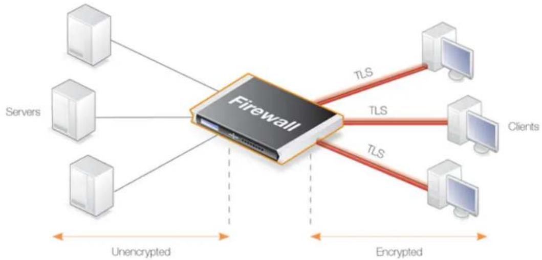
flowchart
graph TD
A["Firewall"] -->|TLS| B["Clients"]
A -->|TLS| C["Clouds"]
A -->|Unencrypted| D["Servers"]
A -->|Encrypted| E["Clouds"]
Figure 6.7. TLS Termination
Advantages of Using NetDefendOS for TLS Termination
TLS can be implemented directly in the server to which clients connect, however, if the servers are protected behind a D-Link firewall, then the firewall can take on the role of the TLS endpoint. This is done by associating the TLS ALG with the IP rule entry that allows the traffic. NetDefendOS
then performs TLS authentication, encryption and unencryption of data to/from clients and the transfer of unencrypted data to/from servers. The IP rule set entry can also perform any address translation that is required.
The advantages of this approach are the following:
- TLS support can be centralized in the D-Link firewall instead of being set up on individual servers.
- Certificates can be managed centrally in the firewall instead of on individual servers. Unique certificates (or one wildcard certificate) does not need to be present on each server.
- The encryption/decryption processing overhead required by TLS can be offloaded to the firewall. This is sometimes referred to as SSL acceleration. Any processing advantages that can be achieved can, however, vary and will depend on the comparative processing capabilities of the servers and the firewall.
- Decrypted TLS traffic can be subject to other NetDefendOS features such as traffic shaping or looking for server threats with IDP scanning.
- TLS can be combined with NetDefendOS server load balancing to provide a means to spread traffic across servers.
URLs Delivered by HTTP Servers
It should be noted that using NetDefendOS for TLS termination will not change URLs in webpages delivered by web servers which lie behind the D-Link firewall.
What this means is that if a client connects to a web server behind the D-Link firewall using the https://protocol then any web pages delivered back containing absolute URLs with the http://protocol (perhaps to refer to other pages on the same site) will not have these URLs converted to https://by NetDefendOS. The solution to this issue is for the servers to use relative URLs instead of absolute ones.
Cryptographic Suites Supported by NetDefendOS TLS
NetDefendOS supports a number of cryptographic algorithms for TLS. These can be enabled or disabled globally using the advanced settings described in Section 13.9, "SSL/TLS Settings".
By default, only the four algorithms which are considered the most secure are enabled. It is not recommended to enable the weaker algorithms and they exist primarily for backwards compatibility.
TLS ALG Restrictions
The following are restrictions that exist when using the TLS ALG:
- Client authentication is not supported (where NetDefendOS authenticates the identity of the client).
- Renegotiation is not supported.
- Sending server key exchange messages is not supported which means the key in the certificate must be sufficiently weak in order to use export ciphers.
Methods of Setting Up the TLS ALG
Deploying the TLS ALG can be done using one of the following methods:
• Using IP Policies
Using an IP Policy object is the recommended setup method. The TLS ALG options are configured directly by setting properties of the IP policy. Note that to configure TLS options with an IP policy, the policy's Service property must be assigned a service object which has its Protocol property set to TLS.
• Using IP Rules
When using IP Rule objects, a TLS ALG object is associated with a Service object that is then associated with an IP rule.
This setup method can be useful for compatibility with older NetDefendOS versions but does not provide any advantages over using an IP policy.
Setting up the TLS ALG Using an IP Policy
The steps for enabling TLS with an IP Policy are as follows:
- Upload the host and root certificates to be used with TLS to NetDefendOS, if not done already.
- Create a new custom Service object based on the TCP protocol and set the Protocol property to TLS.
- Create an IP Policy for the targeted traffic and associate the custom service object with it.
- Enable TLS for the IP Policy and set the values on the policy for the host and root certificates to use. There can only be one host certificate but there can be multiple root certificates.
Using Self-signed Certificates
If the certificates used with the TLS ALG are self-signed then the root and host certificate should both be set to the same certificate.
Example 6.36. TLS ALG Setup Using an IP Policy
In this an IP Policy object will be set up allows access to an internal web server from TLS clients on the Internet. The wan interface is connected to the Internet and has the IPv4 address wan_ip. The web server is located on a DMZ and has the private IPv4 address 10.0.0.5. This policy will perform SAT address translation.
It is assumed that the certificate files for my_root_cert and my_host_cert have already been uploaded to the firewall.
Command-Line Interface
A. Create a custom Service object for TLS:
gw-world:/> add Service ServiceTCPUDP my_tls_service
Type=TCP
DestinationPorts=443
Protocol=TLS
B. Create a SAT IP Policy:
gw-world:/> add IPPolicy Name=SAT_TLS_To_DMZ
SourceInterface=wan
SourceNetwork=all-nets
DestinationInterface=core
DestinationNetwork=wan_ip
Service=my_tls_service
Action=Allow
SourceAddressTranslation=None
DestinationAddressTranslation=SAT
DestinationAddressAction=SingleIP
DestNewIP=10.0.0.5
TLSControl=Yes
TLSHostCert=my_host_cert
TLSRootCert=my_root_cert
Web Interface
A. Create a custom Service object for TLS:
1. Go to: Objects > Services > Add > TCP/UDP Service
2. Now enter:
• Name: my_tls_service
• Type: TCP
• Destination: 443
• Protocol: TLS
- Click OK
B. Create a SAT IP Policy:
1. Go to: Policies > Firewalling > Main IP Rules > Add > IP Policy
2. Now enter:
• Name: SAT_TLS_To_DMZ
• Action: Allow
3. Under Filter enter:
• Source Interface: wan
• Source Network: all-nets
• Destination Interface: core
• Destination Network: wan_ip
• Service: my_tls_service
- Under Source Translation enter:
- Address Translation: None
-
Under Destination Translation enter:
-
Address Translation: SAT
• Address Action: Single IP
• New IP Address: 10.0.0.5 -
Under TLS enter:
-
Enable TLS settings: ON
- Host certificate: my_host_cert
-
Root certificates: my_root_cert
-
Click OK
Setting up the TLS ALG Using an IP Rule
An alternative but more indirect method for setting up the TLS ALG is to use an IP Rule instead of an IP Policy. The steps for doing this are as follows:
- Upload the host and root certificates to be used with TLS to NetDefendOS.
- Define a new TLS ALG object and associate the appropriate host and root certificates with the ALG.
- Create a new custom Service object based on the TCP protocol.
- Associate the TLS ALG object with the newly created service object.
- Create a NAT or Allow IP rule for the targeted traffic and associate the custom service object with it.
- Optionally, a SAT rule can be created to change the destination port for the unencrypted traffic. Alternatively, an SLB_SAT rule can be used to do load balancing (the destination port can also be changed through a custom service object).
6.1.12. DNS ALG
Overview
DNS queries can provide a means of attack for malicious third parties. The DNS ALG feature can be used to monitor DNS queries as they flow through the firewall in the following scenarios:
• DNS queries flowing to the Internet from protected clients behind the firewall.
- DNS queries being sent, usually from the Internet, to a DNS server located on a DMZ behind the firewall.
Setting up the DNS ALG
Deploying the DNS ALG can only be done using an IP policy and requires the following steps:
• Define a DNS Profile object
This object defines how the DNS ALG will behave for the targeted DNS connections. The DNS Profile object properties are described later in this section.
• Associate the profile with an IP Policy for the targeted DNS traffic
The IP Policy must have the following two properties correctly set in order to use the DNS ALG:
i. Service
This should be a Service object that targets the DNS traffic. A predefined service object is provided called dns-all for all DNS traffic. Alternatively, use the predefined objects dns-udp or dns-tcp to target UDP and TCP DNS traffic. A custom service could be used instead. One service object can be shared across multiple IP policies.
Any Service object used with DNS must have its Protocol property set to the value DNS. If this is not the case, the DNS ALG will not be applied to a connection even though it is triggers the IP policy. The Protocol property is already correctly set for the predefined DNS service objects.
ii. DNS Profile
This must be set to a DNS Profile object defined previously. One DNS Profile object can be shared across multiple IP policies and there is no limit on the number of connections handled by a single profile object.
Note that the DNS ALG cannot be used with IP Rule objects.
DNS Profile Properties
A DNS Profile object has the following properties:
- Name
A suitable descriptive name for the profile.
- Log resolved DNS entries
When enabled (the default), a log messaged is generated for each DNS query that is resolved.
- Populate the system's DNS-cache with IP addresses
When enabled (the default), each DNS query the passes through the profile will cause the resolved address to be entered into the DNS cache.
When using wildcards with FQDN Address objects, a DNS Profile must be associated with the allowing IP Policy and this property must be enabled. This is discussed further in Section 3.1.7, "FQDN Address Objects".
• Max UDP query length
The maximum allowed payload size in bytes for UDP DNS queries. The default value is 4096. Queries exceeding this size will be dropped and a log message generated.
• Max UDP response length
The maximum allowed payload size in bytes for UDP DNS responses. The default value is 4096. Responses exceeding this size will be dropped and a log message generated. When using DNSSEC the responses can be large so the default value should be increased.
- Max TCP query length
The maximum allowed payload size in bytes for TCP DNS queries. The default value is 4096. Queries exceeding this size will be dropped and a log message generated.
• Max TCP response length
The maximum allowed payload size in bytes for TCP DNS responses. The default value is 4096. Responses exceeding this size will be dropped and a log message generated. When using DNSSEC the responses can be large so the default value should be increased.
- Recursion Desired flag
DNS recursion means that a DNS server can query other servers to fully resolve the original query. DNS requests have a Recursion Desired (RD) flag which is typically set by, for example, client browsers.
The Recursion Desired flag property is set to Allow so requests with the RD flag set are allowed. However, recursion could be used as a means to launch an amplification attack against a DNS server by sending fake DNS queries from a spoofed IP address so the Recursion Desired flag property could be set to a value of Drop if the desired behavior is to drop any DNS queries with the RD flag set.
- Max question entries
The maximum number of question entries in a query. The default value is 1. It may be possible that a single DNS query might ask for resolution of more than one FQDN but this depends on how the client is configured.
- Scramble query IDs
When enabled (the default) the transaction ID of DNS queries are randomized. This helps defend against cache poisoning caused by the spoofing of DNS queries using non-randomized IDs.
- Allow all classes
This property is disabled by default.
- Allowed classes
When Allow all classes is disabled (the default), this property is set to a list of the allowed classes. Classes can be specified using only their name. The default selection is IN (the Internet class).
- Allow all types
This is enabled by default.
- Allowed types
If Allow all types is disabled, this property is used to specify the allowed types. Types can be specified using only their name. No types are selected by default.
State Tracking is Always Enabled
The DNS ALG has state tracking always enabled and there is no setting to control this. State tracking means that DNS queries and responses are matched to each other. A response with no matching query is automatically dropped.
Forms of DNS Attack and DNS ALG Defense Mechanisms
The DNS ALG is designed to provide a defense against the following forms of DNS attack:
• DNS Cache Poisoning
DNS cache poisoning relies on being able to spoof DNS responses, which means it is mainly applicable to DNS traffic over UDP. An attacker forges and sends a fake/spoofed response to a legitimate DNS query. If the DNS client that sent the original query accepts the faked response, this allows the attacker to inject false entries into the client's DNS cache. The DNS ALG will protect against this in multiple ways. For example, by using the Scramble query ID property of the DNS Profile object (making it more difficult for an attacker to generate a proper response) and also through query/response state tracking (which drops unexpected responses and is always enabled).
In addition, the Recursion Desired flag property of the DNS Profile object can be used to prevent DNS clients from sending queries which request recursion.
• DNS Reflection/Amplification Attacks
In this scenario, a DNS server is used to reflect and/or amplify traffic. An attack can be performed in different ways but generally relies on UDP for the spoofing of the source address of the attack victims. An attacker will generate a large amount of DNS queries to one or more DNS servers which will all respond to the spoofed address. Typically, the attacker will craft the spoofed DNS queries in a way that they will not only reflect, but also amplify traffic (for example, by asking many questions in a single query).
The DNS ALG can help protect against this using the following DNS Profile object properties:
• Max UDP query length
• Max UDP response length
• Max TCP query length
• Max TCP response length
- Allowed classes
- Allowed types
• Max question entries
- DNS Tunneling
In this scenario, an attacker uses DNS traffic to tunnel data through the firewall. The DNS ALG provides protection against basic tunneling by only allowing well-formed DNS traffic through. This means that NetDefendOS validates the DNS traffic against the protocol description in the relevant RFCs. Non-conforming data traffic will be dropped.
More sophisticated tunneling attacks might encode data as valid domain names and store it in the DNS queries/responses. This is difficult to detect. The DNS ALG provides a degree of protection against this using the following DNS Profile object properties:
• Max UDP query length
• Max UDP response length
- Max TCP query length
• Max TCP response length
- Allowed classes
- Allowed types
The dnscontrol CLI Command
The CLI command dnscontrol can be used to display information about all DNS ALG activity by DNS Profile objects. The -stats option displays a summary of all DNS queries passing through all profiles since the last system restart:
gw-world:/> dnscontrol -stats
DNS Control statistics
Forwarded DNS Queries : 2411
Forwarded DNS Responses : 2393
Malformed Client Messages : 6
Malformed Server Messages : 12
Dropped Client Messages : 6
Dropped Server Messages : 12
Current DNS Session : 0
Total DNS Sessions : 2401
The -list option displays a summary of all currently active DNS queries that are passing through all configured DNS Profile objects:
gw-world:/> dnscontrol -list
DNS Control Sessions
ID Creation time Outstanding Transactions
2002 2018-05-14 08:15:14 0
2003 2018-05-14 08:15:14 1
2004 2018-05-14 08:15:14 1
The following should be noted about the above table of information:
• Each DNS query passing through any DNS Profile is assigned a unique ID number, in an ascending sequence.
- The Creation time indicates the time when the profile forwarded the DNS query to the DNS server.
- A number greater than one in the Outstanding Transactions column indicates if any replies from a query to a DNS server are outstanding.
- When all outstanding replies are received then the number outstanding becomes zero but there may be a delay before NetDefendOS removes the query from the list. This is the case with the ID 2002 query in the list above.
To show more information about outstanding queries, the -list option can be used together with the -verbose option, as shown in the example below:
gw-world:/> dnscontrol -list -verbose
DNS Control Sessions
ID Creation time Outstanding Transactions
2011 2018-06-14 09:18:14 1
UDP
192.26.2.2:36318->192.26.1.2:53 [FW] 192.26.2.2:36318->192.26.1.2:53
In the above, a single DNS query is outstanding but this time additional detail is provided to show the protocol used (UDP in this case) and the address translation (if any) performed during DNS forwarding by NetDefendOS. In the above query, the source client address of the query was 192.26.2.2:36318 and the destination server address was 192.26.1.2:53, with no translation being performed. If the connection was subject to a NAT or SAT translation then this would show up
with the -verbose option.
All the options for the dnscontrol command can be found in the separate CLI Reference Guide.
Note that the statistics provided by the dnscontrol command are not available in the NetDefendOS Web Interface.
Example 6.37. Using the DNS ALG with a Protected DNS Server
In this example, the DNS ALG is used to filter UDP DNS queries sent to a protected DNS server on a DMZ which are coming from the Internet. This is illustrated in the diagram below.
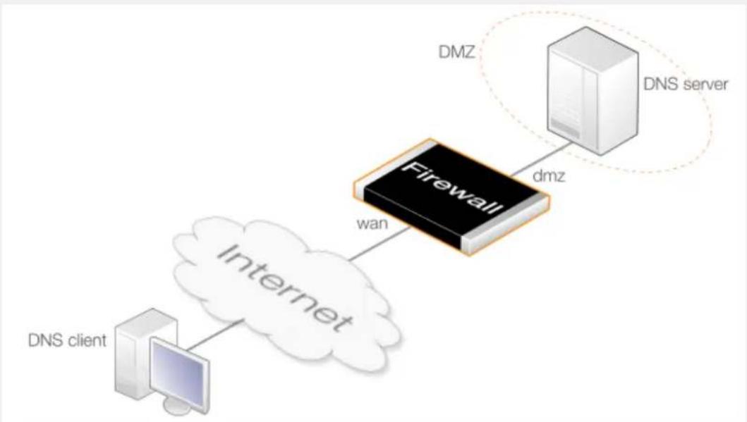
flowchart
graph TD
A["DNS client"] --> B["Internet"]
B --> C["Firewall"]
C --> D["DMZ"]
D --> E["DNS server"]
style C fill:#000,stroke:#fff,color:#fff
style D fill:#f9f,stroke:#000,color:#fff
Command-Line Interface
Create a DNSProfile with default values:
gw-world:/> add Policy DNSProfile my_server_dns_alg
Create a SAT IP policy that uses the profile:
gw-world:/> add IPPolicy Name=SAT_DNS_To_DMZ
SourceInterface=wan
SourceNetwork=all-nets
DestinationInterface=core
DestinationNetwork=wan_ip
Service=dns-udp
Action=Allow
SourceAddressTranslation=None
DestinationAddressTranslation=SAT
DestinationAddressAction=SingleIP
DestNewIP=10.0.0.5
DNS=Yes
DNS_Policy=my_server_dns_alg
Web Interface
Create a DNS Profile with default values:
-
Go to: Policies > Profiles > DNS > Add > DNS Profile
-
Now enter:
- Name: my_server_dns_alg
- Click OK
Create a SAT IP policy that uses the profile:
-
Go to: Policies > Firewalling > Main IP Rules > Add > IP Policy
-
Now enter:
- Name: SAT_DNS_To_DMZ
- Action: Allow
- Under Filter enter:
- Source Interface: wan
- Source Network: all-nets
- Destination Interface: core
- Destination Network: wan_ip
• Service: dns-udp
- Under Source Translation enter:
- Address Translation: None
- Under Destination Translation enter:
- Address Translation: SAT
• Address Action: Single IP
- New IP Address: 10.0.0.5
- Under DNS enter:
- Enable DNS Profile: ON
• DNS Profile: my_server_dns_alg
- Click OK
Example 6.38. Using the DNS ALG with Protected Clients
In this example, clients on the internal protected network lannet are sending DNS queries out to the Internet using NAT via the interface wan. This is illustrated in the diagram below:
In this example, all DNS classes will be allowed but DNS recursion will not be allowed.
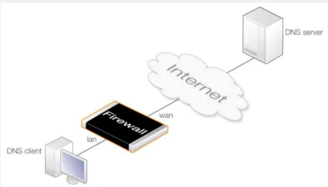
flowchart
graph LR
A["DNS client"] -->|lan| B["Firewall"]
B -->|wan| C["Internet"]
C --> D["DNS server"]
Create a DNSProfile with default values:
gw-world:/> add Policy DNSProfile my_client_dns_alg
RecursionDesiredFlag=Drop
AllowAllClasses=Yes
Create an IPPolicy that uses the profile:
gw-world:/> add IPPolicy Name=NAT_DNS_to_Internet
SourceInterface=lan
SourceNetwork=lannet
DestinationInterface=wan
DestinationNetwork=all-nets
Service=dns-udp
Action=Allow
SourceAddressTranslation=NAT
NATSourceAddressAction=OutgoingInterfaceIP
DNS=Yes
DNS_Policy=my_client_dns_alg
Web Interface
Create a DNS Profile with default values:
-
Go to: Policies > Profiles > DNS > Add > DNS Profile
-
Now enter:
-
Name: my_client_dns_alg
• Recursion Desired flag: Drop -
Allow all classes: Enable
-
Click OK
Create an IP policy that uses the profile:
-
Go to: Policies > Firewalling > Main IP Rules > Add > IP Policy
-
Now enter:
• Name: NAT_DNS_to_Internet
- Action: Allow
-
Under Filter enter:
-
Source Interface: wan
- Source Network: Iannet
- Destination Interface: wan
-
Destination Network: all-nets
• Service: dns-udp -
Under Source Translation enter:
-
Address Translation: NAT
• Address Action: Outgoing Interface IP -
Under DNS enter:
-
Enable DNS Profile: ON
• DNS Profile: my_client_dns_alg -
Click OK
6.2. Web Content Filtering
6.2.1. Overview
As part of the HTTP ALG, NetDefendOS supports Web Content Filtering (WCF) of web traffic, which enables an administrator to permit or block access to web pages based on the content type of those web pages. Web content filtering requires a minimum of administration effort and has very high accuracy. WCF can be configured to work with either HTTP or HTTPS traffic or both.
Methods of Enabling WCF
WCF can be enabled using either of the following methods:
- Using IP Policies
Configuring web content filtering using an IP Policy object is the simplest method and is the recommended way of doing it. WCF is first configured on a new Web Profile object and this object is then associated with an IP policy that triggers on the target traffic. The Protocol property of the Service object assigned to the IP policy must be set to HTTP.
WCF setup using IP policies is discussed further in Section 6.2.2, "WCF Setup Using IP Policies".
- Using IP Rules
With an IP Rule object, WCF is first enabled on an HTTP ALG object. Then, that ALG is associated with a Service object which is in turn associated with an IP rule.
WCF setup using IP rules is discussed further in Section 6.2.3, "WCF Setup Using IP Rules".
WCF Databases
NetDefendOS WCF allows web page blocking to be automated so it is not necessary to manually specify beforehand which URLs to block or to allow. Instead, D-Link maintains a global infrastructure of databases containing huge numbers of current website URL addresses which are already classified and grouped into a variety of categories such as shopping, news, sport, adult-oriented and so on.
The scope of the URLs in the databases is global, covering websites in many different languages and hosted on servers located in many different countries.

Note: WCF database access uses TCP port 9998
When NetDefendOS sends a query to the external WCF databases, it sends it as a TCP request to the destination port 9998.
Therefore, any network equipment through which the request passes, including other firewalls, must not block TCP traffic with destination port 9998.
WCF Processing Flow
When a user of a web browser requests access to a website, NetDefendOS queries the external WCF databases in order to retrieve the category of the requested site. Access to the URL can then be allowed or denied based on the filtering policy that the administrator has put in place for that
particular category.
If access is denied, a web page will be presented to the user explaining that the requested site has been blocked. To make the lookup process as fast as possible NetDefendOS maintains a local cache in memory of recently accessed URLs. Caching can be highly efficient since a given user community, such as a group of university students, often surfs to a limited range of websites.
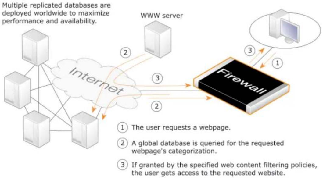
flowchart
graph TD
A["Internet"] -->|2| B["WWW server"]
B -->|3| C["Firewall"]
C -->|1| D["Computer"]
C -->|2| E["User requests a webpage"]
C -->|3| F["A global database is queried for the requested webpage's categorization"]
C -->|3| G["If granted by the specified web content filtering policies, the user gets access to the requested website."]
Figure 6.8. Web Content Filtering Flow
If the requested web page URL is not present in the databases, then the webpage content at the URL will automatically be downloaded to D-Link's central data warehouse and automatically analyzed using a combination of software techniques. Once categorized, the URL is distributed to the global databases and NetDefendOS receives the category for the URL. WCF therefore requires a minimum of administration effort.

Note: New URL submissions are anonymous
New, uncategorized URLs sent to the D-Link network are treated as anonymous submissions and no record of the source of new submissions is kept.
Categorizing Pages and Not Sites
NetDefendOS WCF categorizes web pages and not sites. In other words, a web site may contain particular pages that should be blocked without blocking the entire site. NetDefendOS provides blocking down to the page level so that users may still access those pages of a website that are not blocked by the filtering policy.
WCF and Whitelisting
If a particular URL is whitelisted then it will bypass the WCF subsystem. No classification will be done on the URL and it will always be allowed. This applies if the URL has an exact match with an
entry on the whitelist or if it matches an entry that makes use of wildcarding.
WCF is a Subscription Based Feature
Web content filtering is a feature that is enabled by purchasing a subscription to the service. This subscription is described further in Appendix A, Subscribing to Updates along with details of WCF behavior after subscription expiry.
Introducing Blocking Gradually
Blocking websites can disturb users if it is introduced suddenly. It is therefore recommended that the administrator gradually introduces the blocking of particular categories one at a time. This allows individual users time to get used to the notion that blocking exists and could avoid any adverse reaction that might occur if too much is blocked at once. Gradual introduction also makes it easier to evaluate if the goals of site blocking are being met.
6.2.2. WCF Setup Using IP Policies
WCF can be enabled on an IP Policy object instead of using the combination of an HTTP ALG object with an IP Rule object. Using an IP Policy object provides a more direct method of WCF activation which can be combined with the other options available in an IP policy, such as traffic shaping or anti-virus scanning.
To set up WCF using an IP Policy object, the following steps are required:
- Create a custom Service object for the protocol targeted. Make sure the Protocol property of this object is set to HTTP.
- Create a Web Profile object that has the appropriate settings for the type of web content filtering required.
- Associate these Service and Web Profile objects with an IP Policy object that targets the traffic to be filtered.
Predefined HTTP Services
With NetDefendOS version 11.03 or later, the default configuration will contain predefined Service objects where the Protocol property will already be correctly set. For WCF, this is the http-outbound service. With a NetDefendOS installation that is upgraded to 11.03 or later, the Protocol property will need to be explicitly set on services. For clarity, the example in this section will create a custom Service object and explicitly set the Protocol property.
Fail Mode Action
The fail mode setting determines what happens when web content filtering cannot function. This is usually because NetDefendOS is unable to reach the external databases to perform URL lookup.
Fail mode can have one of the following settings:
- Allow
This is the default value for the property. If the external WCF database is not accessible, URLs are allowed even though they might be disallowed if the WCF databases were accessible.
• Deny
If WCF is unable to function then URLs are denied if external database access to verify them is not possible. The user will see an "Access denied" web page.
Example 6.39. WCF Setup Using an IP Policy
This example shows how to set up web content filtering for HTTP traffic coming from HTTP clients on a protected network which is destined for the Internet. It will be configured to block all shopping sites. It is assumed that an IP Policy object called http_nat_policy already exists and this implements NAT for the client connections to the Internet.
Command-Line Interface
Create a Service object :
gw-world:/> add Service ServiceTCPUDP http_wcf_service
Type=TCP
DestinationPorts=80
Protocol=HTTP
Create a Web Profile object:
gw-world:/> add Policy WebProfile my_wcf_profile
WCF=Yes
WCFCategories=SHOPPING
Modify the IP Policy to use the new service, as well as the profile:
gw-world:/> set IPPolicy http_nat_policy
Service=http_wcf_service
WebControl=Yes
Web_Policy=my_wcf_profile
Web Interface
Create a service object for the traffic:
-
Go to: Local Objects > Services > Add > TCP/UDP service
-
Now enter:
-
Name: http_wcf_service
- Type: TCP
- Destination port: 80
-
Protocol: HTTP
-
Click OK
Create a Web Profile object:
- Go to: Policies > Firewalling > Web > Add > Web Profile
-
Specify the Name as my_wcf_profile
-
Enable Web Content Filtering
- Add Shopping tn the Restricted list
- Click OK
Modify the IP Policy to use the new service and the profile:
- Go to: Policies
- Select http_nat_policy
- Select http_wcf_service from the Service list
- Select the Web Control options
- Enable Web Control
- Select my_wcf_profile from the Web Profile list
- Click OK
6.2.3. WCF Setup Using IP Rules
Setting up WCF with an IP rule requires the following steps:
- Define an HTTP ALG object with Web Content Filtering enabled.
Alternatively, use the Light Weight HTTP ALG (LW-HTTP ALG). This is preferred as it has less system overhead and will provide higher traffic throughput. The disadvantage is that certain features, such as Anti-Virus scanning and stripping static web content, are not supported. The LW-HTTP ALG is discussed further in Section 6.1.2.4, "Light Weight HTTP ALG".
- The ALG object is then associated with a Service object. It is recommended to create a custom Service object for this purpose so the predefined Service objects are left unchanged.
- This Service object is then associated with an IP Rule object to determine which traffic should be subject to filtering. This allows a detailed filtering policy to be defined.
Example 6.40. WCF Setup Using IP Rules
This example shows how to set up web content filtering for HTTP traffic from a protected network to all-nets. It will be configured to block all search sites, and it is assumed that there is using a single NAT IP rule controlling HTTP traffic.
Note that this example configures filtering using an IP Rule object. It could also be done with an IP Policy object and a second example is given later which does this.
Command-Line Interface
First, create an HTTP Application Layer Gateway (ALG) Object:
gw-world:/> add ALG ALG_HTTP content_filtering
WebContentFilteringMode=Enabled
FilteringCategories=SEARCH_SITES
Then, create a service object using the new HTTP ALG:
gw-world:/> add Service ServiceTCPUDP http_content_filtering Type=TCP DestinationPorts=80 ALG=content_filtering
Finally, modify the NAT rule to use the new service. Assume rule is called NATHttp:
gw-world:/> set IPRule NATHttp Service=http_content_filtering
Web Interface
First, create an HTTP Application Layer Gateway (ALG) Object:
- Go to: Objects > ALG > Add > HTTP ALG
- Specify a suitable name for the ALG, for example content_filtering
- Click the Web Content Filtering tab
- Select Enabled in the Mode list
- In the Blocked Categories list, select Search Sites and click the >> button.
- Click OK
Then, create a service object using the new HTTP ALG:
- Go to: Local Objects > Services > Add > TCP/UDP service
- Specify a suitable name for the Service, for example http_content_filtering
- Select TCP in the Type list
- Enter 80 as the Destination Port
- Select the HTTP ALG just created in the ALG list
- Click OK
Finally, modify the NAT IP rule to use the new service:
- Go to: Policies
- Select the NAT rule handling the HTTP traffic
- Select http_content_filtering from the Service list
- Click OK
Web content filtering is now activated for all web traffic from lannet to all-nets.
We can validate the functionality with the following steps:
- On a workstation on the lannet network, launch a standard web browser.
- Try to browse to a search site. For example, www.google.com.
- If everything is configured correctly, the web browser will present a web page that informs
the user about that the requested site is blocked.
Example 6.41. Enabling Audit Mode
This example is based on the same scenario as the previous example, but now with audit mode enabled.
Command-Line Interface
First, create an HTTP Application Layer Gateway (ALG) Object:
gw-world:/> add ALG ALG_HTTP content_filtering
WebContentFilteringMode=Audit
FilteringCategories=SEARCH_SITES
Web Interface
First, create an HTTP Application Layer Gateway (ALG) Object:
- Go to: Objects > ALG > Add > HTTP ALG
- Specify a suitable name for the ALG, for example content_filtering
- Click the Web Content Filtering tab
- Select Audit in the Mode list
- In the Blocked Categories list, select Search Sites and click the >> button
- Click OK
The steps to then create a service object using the new HTTP ALG and modifying the NAT IP rule to use the new service, are described in the previous example.
Web Content Filtering with HTTPS
It is possible in the HTTP ALG to have either the ALG apply to either HTTP or HTTPS traffic or both. If filtering of HTTPS traffic is to work then the Service object associated with the ALG should be one that allows the appropriate port numbers.
For example, the predefined service http-all could be used when both HTTP (port 80) and HTTPS (port 443) traffic are allowed. A custom service may need to be defined and used if an existing predefined service does not meet the requirements of the traffic.
A further point to note with WCF over an HTTPS connection is that if access to a particular site is denied, the HTTPS connection is automatically dropped. This means that the browser will not be able to display the usual NetDefendOS generated messages to indicate that the WCF feature has intervened and why. Instead, the browser will only display its own message to indicate the connection is broken.
The Fail Mode setting can also affect HTTP connections. If no hostname is found in either the ClientHello from the client or the ServerHello from the server in the initial HTTPS handshake session before encrypted packets are sent then the connection is dropped if the Fail Mode action
is Deny and not dropped if the action is Allow.
Audit Mode
In Audit Mode, the system will classify and log all surfing according to the content filtering policy, but restricted websites will still be accessible to the users. This means the content filtering feature of NetDefendOS can then be used as an analysis tool to analysis what categories of websites are being accessed by a user community and how often.
After running in Audit Mode for some period of time, it is easier to then have a better understanding of the surfing behavior of different user groups and also to better understand the potential impact of turning on the WCF feature.
Allowing Override
On some occasions, Active Content Filtering may prevent users carrying out legitimate tasks. Consider a stock analyst who deals with online gaming companies. In his daily work, he might need to browse gambling websites to conduct company assessments. If the corporate policy blocks gambling web-sites, he will not be able to do his job.
For this reason, NetDefendOS supports a feature called Allow Override. With this feature enabled, the content filtering component will present a warning to the user that he is about to enter a website that is restricted according to the corporate policy, and that his visit to the web site will be logged. This page is known as the restricted site notice. The user is then free to continue to the URL, or abort the request to prevent being logged.
By enabling this functionality, only users that have a valid reason to visit inappropriate sites will normally do so. Other will avoid those sites due to the obvious risk of exposing their surfing habits.

Caution: Overriding the restriction of a site
If a user overrides the restricted site notice page, they are allowed to surf to all pages without any new restricted site message appearing again. However, the user is still being logged. When the user has been inactive for 5 minutes, the restricted site page will reappear if they then try to access a restricted site.
Reclassification of Blocked Sites
As the process of classifying unknown websites is automated, there is always a small risk that some sites are given an incorrect classification. NetDefendOS provides a mechanism for allowing users to manually submit a blocked URL for reclassification.
This mechanism can be enabled on a per-HTTP ALG level, which means that the administrator can choose to enable this functionality for regular users or for a selected user group only.
If reclassification is enabled and a user requests a website which is disallowed, the block page will include a Reclassify link. The link will take the user to a special reclassification web page where the blocked URL can be manually entered and a request submitted for it to be reclassified. The processing of these submissions is not immediate and may take some time.
Example 6.42. Reclassifying URLs Blocked by WCF
This example shows how a user may propose a reclassification of a website if he believes it is wrongly classified. This mechanism is enabled on a per-HTTP ALG level basis.
Command-Line Interface
First, create an HTTP Application Layer Gateway (ALG) Object:
gw-world:/> add ALG ALG_HTTP content_filtering
WebContentFilteringMode=Enable
FilteringCategories=SEARCH_SITES
AllowReclassification=Yes
Then, continue setting up the service object and modifying the NAT rule as we have done in the previous examples.
Web Interface
First, create an HTTP Application Layer Gateway (ALG) Object:
- Go to: Objects > ALG > Add > HTTP ALG
- Specify a suitable name for the ALG, for example content_filtering
- Click the Web Content Filtering tab
- Select Enabled in the Mode list
- In the Blocked Categories list, select Search Sites and click the >> button
- Check the Allow Reclassification control
- Click OK
Then, continue setting up the service object and modifying the NAT rule as we have done in the previous examples.
Web content filtering is now activated for all web traffic from lannet to all-nets and the user is able to propose reclassification of blocked sites. Validate the functionality by following these steps:
- On a workstation on the lannet network, launch a standard web browser.
- Try to browse to a search site, for example www.google.com.
- If everything is configured correctly, the web browser will present a block page with a browser link to the reclassification web page.
- Click the reclassification link. The user is now able to submit the URL for reclassification.

Note: Enabling request\_url message generation
The request_url event message will only be generated if event message generation has been enabled in the "parent" IP rule set entry.
6.2.4. WCF Categories
This section provides descriptions for the web content filtering categories available with the Web Content Filtering subsystem.
• Academic Fraud
A website may be categorized under the Academic Fraud category if the site offers or appears to offer services related to Academic Fraud. This includes 3rd party assignment and/or essay writing or any other services aimed at assisting students or researchers to obtain academic qualifications fraudulently.
- Adult Content
A website may be categorized under this category if the site primarily contains adult content.
- Advertising
A website may be categorized under this category if the site primarily contains information relating to advertising.
- Animals:Pets
A website may be categorized under the Animals/Pets category if its content includes information pertaining to Animals, or images relating to animals and/or pets.
- Arts:Culture
A website may be categorized under the Arts/Culture category if its content includes information pertaining to the Arts/Culture, or images relating to the Arts/Culture.
• Auctions
A website may be categorized under the Auctions category if its content includes information pertaining to, or images relating to auctions and/or, the site involves the auctioning of goods and/or services.
• Audio Streaming Services
A website may be categorized under the Audio Streaming Services category if the site hosts or provides, an audio streaming service and/or software that facilitates audio streaming and/or information pertaining to online audio streaming. It does not include streamed radio or TV.
- Backups:Storage
A website may be categorized under the Backups/Storage category if its content includes information pertaining to, or images relating to backup/storage and/or if the site is providing an online backup/storage service.
• Botnets
A website may be categorized under the Botnets category if the site is currently participating in a botnet and/or contains botnet malware. Computer security sites that have information relating to botnets will be classified under IT Security.
- Business Oriented
A website may be categorized under this category if the site primarily contains business related content.
• Charities
A website may be categorized under the Charities if its content includes information pertaining to, or images relating to charities.
- Chat Rooms
A website may be categorized under the Chatrooms category, if the site primarily hosts or provides chat room services and/or its content includes information pertaining to, or images relating to chat Rooms.
- Child Abuse Material
This content is illegal in most jurisdictions in most countries.
- Child Entertainment
A website may be categorized under the Child Entertainment category if its content includes information pertaining to, or images relating to child entertainment.
- Clubs and Societies
A website may be categorized under this category if the site primarily contains club or society related content.
- Computing/IT
A website may be categorized under this category if the site primarily contains computer or IT related content.
- Crime/Terrorism
A website may be categorized under this category if the site primarily contains crime or terrorism related content.
- Dating Sites
A website may be categorized under this category if the site primarily contains personal dating related content.
- Dictionary
A website may be categorized under the Dictionary category if the site is a dictionary site or a site offering similar services, has information and/or images about dictionaries and or dictionary sites.
- Drugs/Alcohol
A website may be categorized under this category if the site primarily contains information relating to alcohol and /or drugs.
- Drugs:illicit
A website may be categorized under the Drugs: illicit category if its content includes information/material/products and/or images that promote or facilitate the use of drugs that are illegal in most jurisdictions. This does not include health information relating to medical use or general use of otherwise illegal drugs.
• Drugs: Pharmaceuticals
A website may be categorized under the Drugs/Pharmaceuticals category if its content includes information pertaining to, or images relating to legal drugs/pharmaceuticals.
• Dynamic DNS
A website may be categorized under the Dynamic DNS category if its content includes information pertaining to, or images relating to and/or is providing a dynamic DNS service.
• E-Banking
A website may be categorized under this category if the site primarily relates to e-banking.
• Educational
A website may be categorized under this category if the site primarily contains information related to education.
• Educational Games
A website may be categorized under the Educational Games category if its content includes software and/or information pertaining to, or images relating to, or is an actual gaming sites that is intended for an educational audience.
- Embedded Threats
A website may be categorized under the Embedded Threats category if its content includes embedded malware. This includes sites that may otherwise be legitimate sites that are currently infected with some form of malware.
- Entertainment
A website may be categorized under this category if the site primarily contains information relating to entertainment.
- Fashion
A website may be categorized under the Fashion category if its content includes information pertaining to, or images relating to fashion.
• Gambling
A website may be categorized under this category if the site relates to gambling.
- Games sites
A website may be categorized under this category if the site primarily contains information relating to online games.
• Government
A website may be categorized under the Government category if the site is run by any government authority (federal, state, local or national). It includes most .gov sites.
• Government Blocking List
A website may be categorized under this category if the site relates to government blocking lists.
- Guns:Weapons
A website may be categorized under the Guns/Weapons category if its content includes information pertaining to, or images relating to Weapons.
• Hacking
A website may be categorized under the Hacking category if its content includes information
pertaining to, or images relating to and/or tools to assist with illegal Hacking. Information relating to malware protection and/or defence against hacking and/or defence against malware is contained within the IT Security category.
• Health Sites
A website may be categorized under the Hobbies category if its content includes information pertaining to health.
• Hobbies
A website may be categorized under the Hobbies category if its content includes information pertaining to, or images relating to hobbies.
- Hosted Services
A website may be categorized under the Hosted Services category if the site provides hosted services or hosting services and/or its content includes information pertaining to, or images relating to, hosted services.
• Humor
A website may be categorized under the Humor category if its content includes information pertaining to, or images relating to Humor. E.g. joke sites.
- Investment Sites
A website may be categorized under the Hobbies category if its content includes information related to investment.
• ISPs
A website may be categorized under the ISPs category if its content includes information pertaining to, or images relating to an Internet Service Provider (ISP).
• IT Forums:Blogs
A website may be categorized under the IT Forums/Blogs category if the site hosts or provides a Internet Forum or Internet Log (BLOG) containing articles, images and/or information pertaining to Information Technology.
• IT Security
A website may be categorized under the IT Security category if its content includes information/software pertaining to, or images relating to information technology security and/or Internet security.
• Job Search
A website may be categorized under this category if the site primarily contains information employment.
• Keyloggers
A website may be categorized under the Keyloggers category if the site contains or may contain keylogging software and or information to facilitate key logging activities, designed for malicious purposes.
- Malicious
A website may be categorized under this category if the site contains malicious code.
• Media:File Sharing
A website may be categorized under the Media Sharing category if its content includes information pertaining to, or images relating to or the provision of file and/or other media sharing services.
• Military
A website may be categorized under the Military category if its content includes information pertaining to, or images relating to military services and/or equipment designed for military use.
- Music Download
A website may be categorized under this category if the site relates to downloading music.
- News
A website may be categorized under this category if the site relates to news.
• Nudity
A website may be categorized under the Nudity category if its content includes non-pornographic information pertaining to, or images relating to or depicting nudity.
• Online Meeting & Collaboration
A website may be categorized under the Online Meeting & Collaboration category if its provides Online Meeting & Collaboration services or information pertaining to online meeting & collaboration. e.g. GoToMeeting, WebEx.
- Pay to Surf
A website may be categorized under the Pay to Surf category if its content includes information pertaining to, or images relating to, or the facilitation of any pay to surf activity.
- Peer To Peer
A website may be categorized under the Peer To Peer category if its content includes information pertaining to, images relating and/or software designed to facilitate peer to peer activity. e.g. Limewire.
- Personal
A website may be categorized under the Personal category if its content includes information and/or images relating to a particular individual. This does not include social networking sites.
• Personal Beliefs/Cults
A website may be categorized under this category if the site primarily contains information relating to beliefs and cults.
- Phishing:Frauds
A website may be categorized under the Phishing/Frauds category if its contains or may contain phishing and/or malware code designed to trick the victim for the purpose of fraud.
• Politics
A website may be categorized under this category if the site primarily contains information relating to politics.
- Proxies:Filtering Bypass
A website may be categorized under the Proxies and Filtering Bypass category if the site is a by pass proxy server or provides software designed to hide the users identity or the source of any browsing traffic.
• Radio
A website may be categorized under the Radio category if the site provides access to online streaming radio and/or provides software designed to facilitate the streaming of online radio.
• Real Estate
A website may be categorized under the Real Estate category if its content includes information pertaining to, or images relating to real estate.
- Remote Control/Desktop
A website may be categorized under this category if the site relates to software for remote control of computers.
• Restaurants:Dining Food
A website may be categorized under the Restaurants/Dinning Food category if its content includes information pertaining to, or images relating to eating out.
- Search Sites
A website may be categorized under this category if the site relates to Internet search engines.
- ShareWare:FreeWare
A website may be categorized under the ShareWare/FreeWare category if the site provides access to Share Ware or Free Ware. Sites that do provide free/share software commonly used by professional IT staff are excluded and come under Computing/IT.
- Shopping
A website may be categorized under this category if the site relates to online shopping.
• Social Networking
A website may be categorized under the Social Networking category if it provides an online social networking service.
- Software Downloading:Sharing
A website may be categorized under the Software Downloading/Sharing category if the site provides a hosting and downloading service for multiple software authors.
- Spam URLs
A website may be categorized under the Spam URLs category if its content includes information pertaining to, or images relating to spamming.
- Special Events
A website may be categorized under the Special Events category if its content includes information pertaining to, or images relating to specific special events.
• Sports
A website may be categorized under this category if the site relates to sports.
- Spyware
A website may be categorized under the spyware category if its content includes spyware.
- Stock Trading
A website may be categorized under the Stock Trading category if its provides the ability to trade stocks online.
• Surveillance Monitoring Site Cams
A website may be categorized under the Surveillance Monitoring Site Cams category if the site provides access to video cams.
- Suspicious
A website may be categorized under the Suspicious category if it hosts or appears to host suspicious content or suspicious software.
• Swimsuit/Lingerie Models
A website may be categorized under this category if the site relates to swimsuit and/or lingerie models.
- Text Messaging
A website may be categorized under the Text Messaging category if its purpose is to send and/or receive text or SMS messages to mobile and/or other devices.
• Tobacco
A website may be categorized under the Tobacco category if its content includes information pertaining to, or images relating to tobacco.
- Travel/Tourism
A website may be categorized under this category if the site primarily contains information relating to travel and tourism.
• TV
A website may be categorized under the TV category if the sites provides online streaming generic TV services and /or software applications designed to facilitate online streaming of Television programs.
• Unions:Professional Organizations
A website may be categorized under the Unions & Professional Organizations category if its content includes information pertaining to, or images relating to unions and/or professional organizations.
- Vehicles
A website may be categorized under the Vehicles category if its content includes information pertaining to, or images relating to motor vehicles, motor bikes and other motorised vehicles. This includes buying & selling motor vehicles, motoring magazines, motor manufacturing sites etc.
• Violence/Undesirable
A website may be categorized under this category if the site primarily contains information relating to violence and other undesirable behavior.
• Viral Video
A website may be categorized under the Viral Video category if its content includes information pertaining to, or images relating to online videos that have gone viral.
- Weather
A website may be categorized under the Weather category if its content includes information pertaining to, or images relating to the weather.
- WWW email sites
A website may be categorized under this category if the site relates to webmail.
6.2.5. Customizing WCF HTML Pages
The Web Content Filtering (WCF) feature of the HTTP ALG make use of a set of HTML files to present information to the user when certain conditions occur such as trying to access a blocked site.
These HTML web pages stored as files in NetDefendOS and these files are known as HTTP Banner Files. The administrator can customize the appearance of the HTML in these files to suit a particular installation's needs. The NetDefendOS management interface provides a simple way to download, edit and re-upload the edited files.

Note
The banner files related to authentication rules and web authentication are a separate subject and are discussed in Section 9.3, "Customizing Authentication HTML".
Available Banner Files
The predefined HTML ALG banner files for WCF are:
- CompressionForbidden
- ContentForbidden
- URLForbidden
- RestrictedSiteNotice
- ReclassifyURL
HTML Page Parameters
The HTML pages contain a number of parameters that can be used as needed. The parameters available are:
• %URL% - The URL which was requested.
- %IPADDR% - The IP address which is being browsed from.
- %REASON% - The reason that access was denied.
- %RESTRICTED_SITE_NOTICE_BEGIN_SECTION% - This begins the restricted site section.
- %RESTRICTED_SITE_NOTICE_FORM% - Allows the restricted notice to be ignored.
- %RESTRICTED_SITE_NOTICE_END_SECTION% - This ends the restricted site section.
- %RECLASSIFICATION_FORM% - Allows site reclassification to be flagged.
By not including the section between %RESTRICTED_SITE_NOTICE_BEGIN_SECTION% and %RESTRICTED_SITE_NOTICE_END_SECTION%, the ability to ignore the restricted site warning can be removed.
Customizing Banner Files
To perform customization it is necessary to first create a new, named ALG Banner Files object. This new object automatically contains a copy of all the files in the Default ALG Banner Files object. These new files can then be edited and uploaded back to NetDefendOS. The original Default object cannot be edited. The following example goes through the necessary steps.
Example 6.43. Editing Content Filtering HTTP Banner Files
This example shows how to modify the contents of the URL forbidden HTML page.
Web Interface
- Go to: System > Advanced Settings > HTTP Banner files > Add > ALG Banner Files
- Enter a name such as new_forbidden and press OK
- The dialog for the new set of ALG banner files will appear
- Click the Edit & Preview tab
- Select URLForbidden from the Page list
- Now edit the HTML source that appears in the text box for the Forbidden URL page
- Use Preview to check the layout if required
- Press Save to save the changes
- Click OK to exit editing
- Go to: Policies > User Authentication User Authentication Rules
- Select the relevant HTML ALG and click the Agent Options tab
- Set the HTTP Banners option to be new_forbidden
- Click OK
- Go to: Configuration > Save & Activate to activate the new file
15. Press Save and then click OK
The new file will be uploaded to NetDefendOS

Tip: Saving changes
In the above example, more than one HTML file can be edited in a session but the Save button should be pressed to save all edits before beginning to edit another file.
Uploading with SCP
It is possible to upload new HTTP Banner files using SCP. The steps to do this are:
- Since SCP cannot be used to download the original default HTML, the source code must be first copied from the Web Interface and pasted into a local text file which is then edited using an appropriate editor.
- A new ALG Banner Files object must exist which the edited file(s) is uploaded to. If the object is called mytxt, the CLI command to create this object is:
gw-world:/> add HTTPALGBanners mytxt
This creates an object which contains a copy of all the Default content filtering banner files.
- The modified file is then uploaded using SCP. It is uploaded to the object type HTTPALGBanner and the object mytxt with the property name URLForbidden. If the edited URLForbidden local file is called my.html then using the Open SSH SCP client, the upload command would be:
scp myhtml admin@10.5.62.11:HTTPAuthBanners/mytxt/URLForbidden
The usage of SCP clients is explained further in Section 2.1.8, "Secure Copy".
- Using the CLI, the relevant HTTP ALG should now be set to use the mytxt banner files. If the ALG us called my_http_alg, the command would be:
set ALG_HTTP my_http_alg HTTPBanners=mytxt
- As usual, the activate followed by the commit CLI commands must be used to activate the changes on the firewall.
6.2.6. The WCF Performance Log
NetDefendOS provides an option for looking more closely at what the web content filtering subsystem is doing and this is called the WCF Performance Log. It is intended to be used by qualified support technicians but it is useful to know that it exists and how to enable it.
When enabled, this feature takes a snapshot of the status of the WCF subsystem and outputs a wcf_performance_notice log event message to all configured log receivers, including Memlog. An example of this log message is shown below:
2014-10-04 08:47:25 Info ALG 200142 wcf_performance_notice
algmod=http cache_size=88 cache_repl_per_sec=3 trans_per_sec=8 queue_len=7
in_transit=2 rtt=1 queue_delta_per_sec=1 server=10.1.0.10 srv_prec=primary
When enabling the performance log, one of the following frequencies must be chosen for how often log generation occurs:
- Every 5 seconds.
• Every 10 seconds.
• Every 30 seconds.
• Every 60 seconds.
• Every 300 seconds.
• Every 600 seconds.
Each wcf_performance_notice log message contains the following fields:
- cache\_size
The size of the WCF cache which contains the most recent URLs looked up against the external WCF database server.
- trans\_per\_sec
The number of database queries being sent per second. URLs are not always sent singly. NetDefendOS will send batches when there is more than one waiting for processing against the database.
- queue\_len
The length of the queue of URLs awaiting processing by the external WCF database server.
- in\_transit
The number of URLs in the queue where a request has been sent to the WCF database server but a reply has not yet been received.
• rtt
The round-trip time for the last WCF database server lookup.
- queue\_delta\_per\_sec
This is the amount the queue of waiting requests increases or decreases per second.
- server
The IPv4 address of the server performing the database lookup.
- srv\_prec
The precedence of the responding server. A server with a higher precedence may not have responded to the request and the next lower precedence has been selected.
The last snapshot sent as a log message can also be viewed on a management console using the NetDefendOS CLI command httpalg -wcf. Below is an example of the output from the command and as shown there is additional information compared with the wcf_performance_notice log event message.
gw-world:/> httpalg -wcf
Dynamic Web Content Filter Statistics
Counter Value
Cache Size: 62 URLs
Cache Hit Rate: 0 per second.
Cache Miss Rate: 0 per second.
Request Lookups: 0 per second.
Request Queue Length: 0 URLs.
Requests In Transit: 0 URLs.
RTT per transaction: 40 milliseconds.
Request Queue Delta: 0 URLs per second.
Cache Replacements: 0 URLs per second.
Last Cache Repl. - Hit Rate Idle: N/A.
Last Cache Repl. - Idle TTL Left: N/A.
Last Cache Repl. - Session TTL Left: N/A.
Server: 192.168.1.18
Connection Lifetime: 574 seconds.

Note: This is in techsupport command output
The output from the CLI command httpalf -wcf is included in the output from the techsupport command. See Section 2.6.10, "The techsupport Command".
Enabling the WCF Performance Log
The example below shows how the WCF performance log feature is enabled.
Example 6.44. Enabling the WCF Performance Log
This example enables the WCF performance log feature so that a wcf_performance_notice log event message is generated every 5 seconds. This log message provides a snapshot of the WCF subsystem.
Command-Line Interface
gw-world:/> set Settings MiscSettings WCFPerfLog=5
Web Interface
- Go to: System > Advanced Settings > Misc. Settings
- Set WCF Performance Log to Every 5 Seconds
- Click OK
6.3. Email Control
Email traffic can be a major concern for a system administrator, both because of its volume and because of the security threats it can carry. Unsolicited email, often referred to as Spam, is sent out by groups known as spammers in massive quantities and can waste resources, transport malware, as well as try to direct the recipient to webpages that might present further security risks.
The NetDefendOS anti-spam feature can be set up of the following ways:
• IP Policy based Email Filtering for IMAP, POP3 and SMTP
Email filtering can be enabled on an IP Policy which targets the email traffic and this is the recommended method for setup. It makes available all the email filtering tools available in NetDefendOS. This includes a comprehensive anti-spam capability.
This type of email filtering is described in Section 6.3.1, "Email Control Profiles with IP Policies".
• IP Rule Based Email Filtering for SMTP
Email filtering using IP rules provides email filtering through an SMTP ALG objects. Email filtering using IP rules can only be performed on SMTP traffic and is normally only used for compatibility with older NetDefendOS versions.
This type of email filtering is described in Section 6.3.3, "SMTP Anti-Spam with IP Rules".
In both of the above ways of configuring email filtering, DNSBL servers might be used and DNSBL server usage with NetDefendOS is described generally for both methods in Section 6.3.2, "DNSBL Processing".
6.3.1. Email Control Profiles with IP Policies
With IP policies, email filtering can be applied to IMAP, POP3 and SMTP traffic using IP policies. This is done by creating an Email Control Profile and associating it with an IP Policy object. With IMAP and POP3 filtering, emails cannot be dropped when they fail filtering but only marked as failed. With SMTP, emails can be dropped or forwarded.
Setting Up Email Filtering with IP Policies
IP policy based email filtering is set up with the following steps:
- Create an Email Control Profile object which defines how email is to be filtered. If anti-spam filtering is required it must be explicitly enabled in the profile (by default, it is disabled).
- Optionally add one or more Email Filter objects as children to the Email Control Profile object. Each will specify an email address (or addresses using wildcards) which are to be blacklisted (automatically rejected before filtering) or whitelisted (never subject to filtering).
- Associate the Email Control Profile object created above with an IP Policy object which triggers on the email traffic. Only a single profile can be associated with an IP policy.
- The Service property for this IP policy must trigger on the IMAP, POP3 or SMTP protocols so it must be set to an appropriate Service object. The Service object used must have its Protocol property set to IMAP, POP3 or SMTP (whichever applies).
The predefined IMAP, POP3 and SMTP services could be used by setting their Protocol property to be IMAP or POP3 or SMTP. However, it is recommended to instead create a new custom Service object and this is done in the setup example found at the end of this section.
- Optionally enable anti-virus scanning on the IP policy. This will scan any email attachments for viruses and will function with the IMAP, POP3 or SMTP protocol. Anti-virus scanning is discussed further in Section 6.4, "Anti-Virus Scanning".

Note: A service group cannot be used for email filtering
It is not possible use a custom Service Group object for IP policy based email filtering which combines any of the IMAP, POP3 or SMTP protocols. Separate IP policies with separate services for IMAP, POP3 or SMTP must be configured.
General Email Control Profile Settings
The following Email Control Profile options are available for all types of traffic.
- Anti-Spam
When enabled, anti-spam scoring is applied to emails to determine if it could be spam. The anti-spam feature is described further later in this section.
By default, this option is disabled.
- Blacklist Subject Tag
This is the text inserted into the subject field of an email if it is found on the blacklist for this profile.
Protocol Specific Options
The following additional options are available for when the profile is used with specific email related protocols:
- SMTP Settings
These settings relate to processing by the SMTP ALG and are described further in Section 6.1.5, "SMTP ALG".
- POP3 Settings
These settings relate to processing by the POP3 ALG and are described further in Section 6.1.6, "POP3 ALG".
- IMAP Settings
These settings relate to processing by the IMAP ALG and are described further in Section 6.1.7, "IMAP ALG".
Email Address Whitelist/Blacklist
One or more Email Filter objects can be added as children to an Email Control Profile object. Each filter specifies one address or, using wildcards, a series of addresses that are to be always dropped (blacklisted) or always allowed (whitelisted).
The wildcard asterisk ("*") character can be used to specify any string. For example, the string
*.@example.com represents any email address from the example.com domain. The question mark ("?") character can also be used to represent any single character.
Whitelisting and blacklisting takes precedence over all other email filtering. Whitelisted emails will never be subject to anti-spam or anti-virus processing if either of those is enabled.
If an email comes from a blacklisted domain, the mail is not dropped. Instead, the subject line has a configurable text string inserted at the beginning. By default, this string is:
*** BLACK LISTED ***
However, this text can be set by the user, as previously described.
Note that some IMAP clients may download and display the headers of emails before they download the email body. This can mean that the blacklist text may not be displayed correctly in the subject line with such clients. This is discussed further in the later section on anti-spam since the same problem can exist with flagging spam in the email subject line.
Anti-Spam and Filter Scoring
The anti-spam feature of email filtering using IP policies must be explicitly enabled in the Email Control Profile object used with an IP policy. Once enabled, a score is calculated by adding together the sub-scores of the enabled anti-spam filters. The score is used in the following ways:
- If the total score is equal to or greater than the specified Tagging Threshold (the default value is 10) then an email is considered to be SPAM and tagged as such.
- For SMTP only, if the total score is equal to or greater than the specified Reject Threshold (the default value is 20) then an email is dropped.
Each anti-spam filter can be enabled or disabled and they are comprised of the following list:
- Domain Verification
When enabled, NetDefendOS will perform a DNS MX query, requesting the IP address of a mail server associated with the email sender's domain. For example, the sender email address might be some.name@example.com so NetDefendOS will send an MX query to the configured DNS server for the mail server at example.com.
If the DNS server recognizes the domain name, NetDefendOS takes no action. If the DNS server does not recognize the domain, NetDefendOS will add the sub-score for this filtering option to the overall anti-spam score.
Note that at least one DNS server must be configured in NetDefendOS for this option to work. If no DNS server is configured, this test will not be performed and its sub-score will not be added. Configuring DNS servers is described in Section 3.10, "DNS".
This filtering option is enabled by default.
- Malicious Link Protection
This option neutralizes undesirable or malicious HTML links inside emails. It is enabled by default and is discussed later in this section in more detail. Finding a single triggering link will add this option's sub-score (a default value of 10) to the total score. Malicious link protection is described in depth later in this section.
• DNS Blacklists
By enabling the DNS Blacklists option, up to 10 different DNS Blacklist (DNBL) servers can be
specified, each with its own sub-score (the default value is 10 per server) that will be added to the total score if that server flags an email as spam.
If a DNSBL server is not responding then its sub-score is not included in the final score calculation. How DNSBL functions is explained further in Section 6.3.2, "DNSBL Processing". For an example of configuring DNSBL anti-spam filtering, see Example 6.14, "IMAP ALG Setup".
Email Tagging
If an email score exceeds the Tagging Threshold property, it is marked as being SPAM. This is done in either or both of two ways:
- Tag Subject
This is enabled by default and adds text to the subject line of an email. The default text is "*** SPAM ***" but this can be set to any string.
An example of this kind of tagging is if the original Subject field is:
Buy this stock today!
If the tag text is defined to be "*** Probably SPAM **", then the modified email's Subject field will become:
*** Probably SPAM *** Buy this stock today!
The line above is what the email's recipient will see in the summary of their inbox contents. The individual user could then decide to set up their own filters in the local client to deal with such tagged emails, possibly sending it to a separate folder.
- Tag Header
This is also enabled by default and it inserts X-Spam information into the bottom of the email header data which describes the anti-spam processing that has been performed on the email. When enabled, this indicates if the email is considered spam or not. This information may not be immediately visible to the recipient but many email clients will provide the option to view it and many will also allow it to be part of the client's filtering criteria.
The X-Spam fields inserted by NetDefendOS are as follows:
i. X-Spam-Checker-Version - The software that tagged the email.
ii. X-Spam-Status - A list that includes the scoring and the filters applied.
iii. X-Spam-Flag - Included only for emails marked as spam and always Yes.
iv. X-Spam-Report - A detailed list of the results from applied filters.
An example of inserted X-SPAM information for an email that was flagged as spam is the following:
X-Spam-Checker-Version: D-Link NetDefendOS on Device
X-Spam-Status:
Yes, score=30 required=10 tests=LINK_PROTECTION,DNS_BLACKLIST_1
X-Spam-Flag: Yes
X-Spam-Report:
* 10 LINK_PROTECTION: Contained undesirable web links
* 10 DNS_BLACKLIST_1: Blacklisted source IP address
An example of inserted X-SPAM information for an email that was not flagged as spam is the following:
X-Spam-Checker-Version: D-Link NetDefendOS on Device
X-Spam-Status: No, score=5 required=10 tests=DNS_BLACKLIST_1
Malicious Link Protection
The Malicious Link Protection filter for anti-spam allows undesirable links in email traffic to be neutralized as the email passes through NetDefendOS. It is part of anti-spam filtering and can only be enabled when anti-spam is enabled. Links within emails are evaluated by NetDefendOS using the Web Content Filtering subsystem which is described in Section 6.2, "Web Content Filtering".
The following points should be noted for the link protection:
- Link protection will only examine the first 10 links in an email. After that no more link processing is performed for subsequent links.
- When a link triggers web content filtering, the link will still appear in the mail but will be disabled so it cannot be clicked.
- If one or more links trigger the specified link protection score (see properties below) will be added just once for an email to the overall anti-spam score.
The following properties of an Email Control Profile are used to control link protection:
- Link Protection
By default, link protection is enabled if anti-spam is enabled. Disable this property to switch it off for all emails.
- Link Protection Score
This is the score that is added to the total anti-spam score if just one link is found that triggers wen content filtering. The default value is 10.
- Link Protection Categories
A subset of the list of all web content filtering categories can be defined and this subset will be disallowed. By default, the is set to a limited subset. All available categories are described in Section 6.2, "Web Content Filtering".
• Non-Managed Action
This determines what to do with a link that could not be determined to belong to one of the web content filtering categories. The choice is either to allow such links (the default) or to disallow them.

Note: A valid web content filtering subscription is required
The malicious link protection filter will only function if NetDefendOS also has a valid subscription for the web content filtering feature since this is used to evaluate links.
IMAP Clients May Display Incorrect Header Information
Email clients using IMAP to retrieve email details from an email server, can download and display the headers of emails before they download the email body. This means the user can only download the body of emails they want to read based on the header information.
Since NetDefendOS may perform some of its spam scoring based on the email body, the initial header information displayed by the client may not yet correctly show the spam text in the subject line. When the email body is eventually downloaded, NetDefendOS examines it and the header information will be updated if the mail is now considered to be spam. However, some email clients may not update the displayed header information and will continue to display the original unflagged header information. This is not something that can be controlled by NetDefendOS.
In all cases, the spam related log messages generated by NetDefendOS and the spam related statistics it keeps will correctly reflect which emails it has classified as spam.
As mentioned previously, a similar problem can arise with blacklisting and IMAP clients. The initial header information displayed by the client may not correctly show the blacklist text.
6.3.2. DNSBL Processing
DNSBL servers can be used with both IP policy based anti-spam and also with SMTP ALG based anti-spam. This section explains the way they function and how they are used with NetDefendOS anti-spam and is applicable to both DNSBL usage with email control profiles and IP policies as well as to the SMTP ALG being used with IP rules. Further explanation of DNSBL usage with IP rules can be found in Section 6.3.2, "DNSBL Processing".
Public DNSBL Databases
A number of trusted organizations maintain publicly available databases of the origin IP address of known spamming SMTP servers and these can be queried over the Internet. These lists are known as DNS Black List (DNSBL) databases and the information is accessible using a standardized query method supported by NetDefendOS.
DNSBL Server Usage By NetDefendOS
When the NetDefendOS anti-spam filtering feature is configured, the IP address of the email's sending server is sent to one or more DNSBL servers to find out if any DNSBL servers think the email is from a spammer or not. NetDefendOS examines the IP packet headers to do this. The diagram below illustrates NetDefendOS's interaction with DNSBL servers.
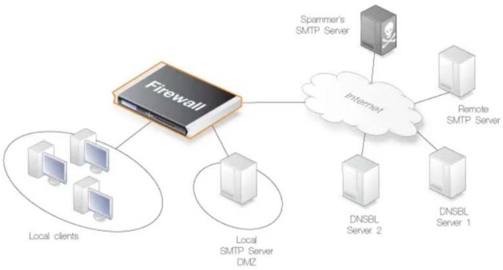
flowchart
graph TD
A["Firewall"] --> B["Internet"]
B --> C["Spammer's SMTP Server"]
B --> D["Remote SMTP Server"]
B --> E["DNSBL Server 1"]
B --> F["DNSBL Server 2"]
B --> G["Local SMTP Server DMZ"]
B --> H["Local clients"]
Figure 6.9. DNSBL Anti-Spam Processing
The reply sent back by a DNSBL server is either a not listed response or a listed response. In the latter case of being listed, the DNSBL server is indicating the email might be spam and it will usually also provide information known as a TXT record which is a textual explanation for the listing.
Note that the TXT record is not used by IP policy based anti-spam. If anti-spam is configured with IP rules using an SMTP ALG object then the record is part of the X-SPAM information which is optionally inserted into the body of an email.

Tip: Finding a list of available DNSBL servers
A list of public DNSBL servers can be found at: http://en.wikipedia.org/wiki/Comparison_of_DNS_blacklists.
Creating a DNSBL Consensus
Multiple DNSBL servers can be specified in an Email Control Profile object which is then assigned to an IP policy that triggers on the targeted traffic. A weight is also assigned to each DNSBL server and this must be an integer greater than zero. A weighted sum can then be calculated based on all server responses and the following thresholds for the sum can be specified in the email control profile:
- Tag Threshold
If the sum is greater than or equal to this value then the email is considered as probabil being spam but forwarded to the recipient with notifying text inserted into it.
- Reject Threshold
If the sum is greater than or equal to this value then the email is considered to be definitely spam and is discarded or alternatively sent to a single, special mailbox. This value will only apply to SMTP traffic.
If it is discarded then the administrator has the option that an error message is sent back to
the sending SMTP server (this error message is similar to the one used with blacklisting).
A DNSBL Threshold Calculation Example
As an example, suppose that three DNSBL servers are configured: dnsbl1, dnsbl2 and dnsbl3. Weights of 3, 2 and 2 are assigned to these respectively. The spam threshold is then set to be 5.
If dnsbl1 and dnsbl2 say an email is spam but dnsbl3 does not, then the total calculated will be 3+2+0=5 . Since the total of 5 is equal to (or greater than) the threshold then the email will be treated as spam.
If the Drop threshold in this example is set at 7 then all three DNSBL servers would have to respond in order for the calculated sum to cause the email to be dropped (3+2+2=7).
Allowing for Failed DNSBL Servers
If a query to a DNSBL server times out then NetDefendOS will consider that the query has failed and the weight given to that server will be automatically subtracted from both the spam and drop thresholds for the scoring calculation done for that email.
If enough DNSBL servers do not respond then this subtraction could mean that the threshold values become negative. Since the scoring calculation will always produce a value of zero or greater (servers cannot have negative weights) then all email will be allowed through if both the Spam and Drop thresholds become negative.
A log message is generated whenever a configured DNSBL server does not respond within the required time. This is done only once at the beginning of a consecutive sequence of response failures from a single server to avoid unnecessarily repeating the message.
DNSBL Server Query Logging
The following types of log messages are generated by NetDefendOS as a result of DNSBL server queries:
- Logging of dropped or spam tagged emails - These log messages include the source email address and IP as well as its weighted points score and which DNSBLs caused the event.
• DNSBLs not responding - DNSBL query timeouts are logged. - All defined DNSBLs stop responding - This is a high severity event since all email will be allowed through if this happens.
6.3.3. SMTP Anti-Spam with IP Rules
This section describes anti-spam setup using an SMTP ALG object configured using IP rules.
Anti-Spam Setup with IP Rules
To set up spam filtering in the SMTP ALG, the following list summarizes the steps:
• Create a new SMTP ALG object.
- Specify the DNSBL servers that are to be used. There can be one or multiple. Multiple servers can act both as backups to each other as well as confirmation of a sender's status.
- Specify a weight for each server which will determine how important it is in deciding if email is spam or not in the calculation of a weighted sum.
- Specify the thresholds for designating any email as spam. If the weighted sum is equal or greater than these then an email will be considered to be spam. Two thresholds are specified:
i. Spam Threshold - The threshold for tagging mail as spam.
ii. Drop Threshold - The threshold for dropping mail.
The Spam Threshold should be less than the Drop Threshold. If the two are equal then only the Drop Threshold applies.
- Specify a textual tag to prefix to the Subject field of email designated as spam.
- Optionally specify an email address to which dropped email will be sent (as an alternative to simply discarding it). Optionally specify that the TXT messages sent by the DNSBL servers that failed are inserted into the header of these emails.
Creating a DNSBL Consensus
The administrator can configure the NetDefendOS SMTP ALG to consult multiple DNSBL servers in order to form a consensus opinion on an email's origin address. For each new email, configured servers are queried to assess the likelihood that the email is spam, based on its origin address.
With the SNMP ALG, the administrator assigns a weight greater than zero to each configured DNSBL server so that a weighted sum can then be calculated based on all responses. The administrator can then configure one of the following actions based on the weighted sum calculated:
- Dropped
If the sum is greater than or equal to a predefined Drop threshold then the email is considered to be definitely spam and is discarded or alternatively sent to a single, special mailbox.
If it is discarded then the administrator has the option that an error message is sent back to the sending SMTP server (this error message is similar to the one used with blacklisting).
- Flagged as Spam
If the sum is greater than or equal to a predefined Spam Threshold then the email is considered as probably being spam but forwarded to the recipient with notifying text inserted into it.
Alternative Actions for Dropped Spam
If the calculated sum is greater than or equal to the Drop threshold value then the email is not forwarded to the intended recipient. Instead the administrator can choose one of two alternatives for dropped email:
- A special email address can be configured to receive all dropped email. If this is done then any TXT messages sent by the DNSBL servers (described next) that identified the email as spam can be optionally inserted by NetDefendOS into the header of the forwarded email.
- If no receiver email address is configured for dropped emails then they are discarded by NetDefendOS. The administrator can specify that an error message is sent back to the sender address along with the TXT messages from the DNSBL servers that failed the email.
Tagging Spam
If an email is considered to be probably spam because the calculated sum is above the spam threshold but it is below the drop threshold, then the Subject field of the email is changed and prefixed with a message and the email is forwarded on to the intended recipient. The tag message text is specified by the administrator but can be left blank (although that is not recommended).
An example of tagging might be if the original Subject field is:
Buy this stock today!
And if the tag text is defined to be "*** SPAM **", then the modified email's Subject field would become:
*** SPAM *** Buy this stock today!
And this is what the email's recipient will see in the summary of their inbox contents. The individual user could then decide to set up their own filters in the local client to deal with such tagged emails, possibly sending it to a separate folder.
Adding X-Spam Information
If an email is determined to be spam and a forwarding address is configured for dropped emails, then the administrator has the option to Add TXT Records to the email. A TXT Record is the information sent back from the DNSBL server when the server thinks the sender is a source of spam. This information can be inserted into the header of the email using the X-Spam tagging convention before it is sent on. The X-Spam fields added are:
• X-Spam-Flag - This value will always be Yes.
• X-Spam-Checker-Version - The software that tagged the email.
• X-Spam-Status - This will always be DNSBL.
• X-Spam-Report - A list of the DNSBL servers that flagged the email as spam.
- X-Spam-TXT-Records - A list of TXT records sent by the DNSBL servers that identified the email as spam.
• X-Spam_Sender-IP - IP address used by the email sender.
These fields can be referred to in filtering rules set up by the administrator in mail server software.
Verifying the Sender Email
As part of the anti-spam module, the option exists to check for a mismatch of the "From" address in the SMTP protocol command with the actual email header "From" address. Spammers can deliberately make these different to get email past filters so this feature provides an extra check on email integrity.
If a mismatch is detected, one of two actions can be configured:
• The email is dropped.
- Allow the email to pass but tag it using the configured spam tag.
When sender address verification is enabled, there is an additional option to only compare the domain names in the "From" addresses.
For the DNSBL subsystem overall:
• Number of emails checked.
• Number of emails spam tagged.
• Number of dropped emails.
For each DNSBL server accessed:
• Number of positive (is spam) responses from each configured DNSBL server.
• Number of queries sent to each configured DNSBL server.
• Number of failed queries (without replies) for each configured DNSBL server.
The dnsbl CLI Command
The dnsbl CLI command provides a means to control and monitor the operation of the anti-spam subsystem when the SMTP ALG is set up with IP rules (it does not track DNSBL usage with IP policies).
The dnsbl command on its own without options shows the overall status of all ALGs. If the name of the SMTP ALG object on which DNSBL spam filtering is enabled is my_smtp_alg then the output would be:
gw-world:/> dnsbl
DNSBL Contexts:
Name Status Spam Drop Accept
my_smtp_alg active 156 65 34299
alt_smtp_alg inactive 0 0 0
The -show option provides a summary of the spam filtering operation of a specific ALG. It is used below to examine activity for my_smtp_alg although in this case, the ALG object has not yet processed any emails.
gw-world:/> dnsbl my_smtp_alg -show
Drop Threshold : 20
Spam Threshold : 10
Use TXT records : yes
IP Cache disabled
Configured BlackLists : 4
Disabled BlackLists : 0
Current Sessions : 0
Statistics:
Total number of mails checked : 0
Number of mails dropped : 0
Number of mails spam tagged : 0
Number of mails accepted : 0
BlackList Status Value Total Matches Failed
b.barracudacentral.org active 25 0 0 0
cbl.abuseat.org active 20 0 0 0
dnsbl.sorbs.net active 5 0 0 0
asdf.egrhb.net active 5 0 0 0
To examine the statistics for a particular DNSBL server, the following command can be used.
gw-world:/> dnsbl smtp_test b.barracudacentral.org -show
BlackList: b.barracudacentral.org
Status : active
Weight value : 25
Number of mails checked : 56
Number of matches in list : 3
Number of failed checks (times disabled) : 0
To clean out the dnsbl cache for my_smtp_alg and to reset all its statistical counters, the following command option can be used:
gw-world:/> dnsbl my_smtp_alg -clean
Email Addresses are Cached for Performance
To speed processing, the SMTP ALG maintains a cache of the most recently looked-up sender "From" IP addresses in local memory. If the cache becomes full then the oldest entry is written over first. There are two SMTP ALG object properties which can be configured for this address cache:
- Cache Size
This is the number of entries that the cache can contain. If set to zero, the cache is not used. Increasing the cache size increases the amount of NetDefendOS memory required for anti-spam.
- Cache Timeout
The timeout determines how long any address will be valid for once it is saved in the cache. After this period of time has expired, a new query for a cached sender address must be sent to the DNSBL servers.
The default value if 600 seconds.
The address cache is emptied when NetDefendOS restarts or a reconfiguration operation is performed.
6.4. Anti-Virus Scanning
6.4.1. Overview
The anti-virus scanning feature optionally protects against malicious code carried by any of the following:
- Files passing through the firewall between server and client. The transfer could be done using any of the following protocols:
i. HTTP.
ii. FTP.
iii. POP3.
iv. SMTP.
v. IMAP (with IP Policy objects only).
- Scripts contained within webpages delivered via HTTP.
- URLs contained within webpages delivered via HTTP.
Malicious code in downloads can have different intents ranging from programs that merely cause annoyance to more sinister aims such as sending back passwords, credit card numbers and other sensitive information. The term "Virus" can be used as a generic description for all forms of malicious code carried in files.
Combining with Client Anti-Virus Scanning
Unlike IDP, which is primarily directed at attacks against servers, anti-virus scanning is focused on downloads by clients. NetDefendOS anti-virus is designed to be a complement to the standard anti-virus scanning normally carried out locally by specialized software installed on client computers. It is not intended as a complete substitute for local scanning but rather as an extra shield to boost client protection. Most importantly, it can act as a backup for when local client anti-virus scanning is not available.
Methods of Enabling Anti-Virus Scanning
Anti-virus scanning can be enabled in any of the following ways:
- Using an IP Policy
This is the recommended way to set up scanning. An Anti-Virus Profile object is created and this is associated with an IP Policy that triggers on the target traffic. Note that the Service assigned to the IP policy has to have its Protocol property set to the targeted protocol.
- Using and IP Rule
With an IP Rule object, anti-virus scanning is first enabled on the relevant ALG for the targeted traffic. Then, that ALG is associated with a Service object which is in turn associated with an IP rule that triggers on the target traffic.
Configuring anti-virus scanning with either an IP rule or an IP policy is described further in Section 6.4.3, "Activating Anti-Virus Scanning".
6.4.2. Implementation
Streaming
As a data transfer is streamed through the firewall, NetDefendOS will scan the data for the presence of viruses if the anti-virus module is enabled. Since data is being streamed and not being read completely into memory, a minimum amount of memory is required and there is minimal effect on overall throughput.
Pattern Matching
The inspection process is based on pattern matching against a database of known virus patterns and can determine, with a high degree of certainty, if a virus is in the process of being downloaded to a user behind the firewall. Once a virus is recognized in the contents of a file, the download can be terminated before it completes.
Types of Data Scanned
As described above, anti-virus scanning is enabled on a per ALG basis and can scan data downloads associated with the HTTP, FTP, SMTP and POP3 ALGs. More specifically:
• Any uncompressed file type transferred through these ALGs can be scanned.
- If the data file transferred has been compressed, ZIP and GZIP files can be scanned as well as nested compressed files within them (up to 10 levels of nesting).
• For the HTTP ALG, webpage scripts and URLs are scanned.
Messages displayed by the HTTP ALG
If enabled through the HTTP ALG, webpage scripts and URLs as well as files can be scanned for malicious code. If a threat is encountered, the connection is dropped and NetDefendOS will generate a log message for the event. HTTPS traffic cannot be scanned so this does not apply for that protocol.
As well as the connection being dropped, NetDefendOS will try to insert a message into the web browser HTML of the affected user indicating the action taken (in some cases it might not be possible to do this successfully). For malicious files and scripts, the following is an example of an inserted message:
A virus has been detected
The rest of this file will be blocked
Infected File: filename.txt
Virus Name: examplename
Figure 6.10. Anti-Virus Malicious File Message
For malicious URLs, the message displayed will be similar to the following:
A malicious URL has been detected
The request of this URL will be blocked
URL: example.url
Figure 6.11. Anti-Virus Malicious URL Message
Simultaneous Scans
There is no fixed limit on how many anti-virus scans can take place simultaneously in a single D-Link firewall. However, the available free memory can place a limit on the number of concurrent scans that can be initiated.
Protocol Specific behavior
Since anti-virus scanning is implemented through an Application Level Gateway (ALG), specific protocol specific features are implemented in NetDefendOS. With FTP, for example, scanning is aware of the dual control and data transfer channels that are opened and can send a request via the control connection to stop a download if a virus in the download is detected.
Relationship with IDP
A question that is often posed is the "ordering" of Anti-virus scanning in relation to IDP scanning. In fact, the concept of ordering is not relevant since the two scanning processes can occur simultaneously and operate at different protocol levels.
If IDP is enabled, it scans all packets designated by a defined IDP rule and does not take notice of higher level protocols, such as HTTP, that generate the packet streams. However, Anti-virus is aware of the higher level protocol and only looks at the data involved in file transfers. Anti-virus scanning is a function that therefore logically belongs in an ALG, whereas IDP does not belong there.
Subscribing to the D-Link Anti-Virus Service
The D-Link anti-virus feature requires the purchase of a renewable subscription in order for it to function. This includes regular updates of the Kaspersky SafeStream database during the subscription period with signatures for the latest virus threats.
Anti-virus subscriptions are discussed further in Appendix A, Subscribing to Updates.
The Signature Database
NetDefendOS anti-virus scanning is implemented using the SafeStream™ II virus signature database. The SafeStream II database is created and maintained by Kaspersky, a company which is a world leader in the field of virus detection. The database provides protection against virtually all known virus threats including trojans, worms, backdoor exploits and others. The database is also thoroughly tested to provide near zero false positives.
Database Updates
The SafeStream database is updated on a daily basis with new virus signatures. Older signatures
are seldom retired but instead are replaced with more generic signatures covering several viruses. The local NetDefendOS copy of the SafeStream database should therefore be updated regularly and this updating service is enabled as part of a D-Link subscription.
Database updating is described further in Appendix A, Subscribing to Updates along with a description of anti-virus behavior after subscription expiry.
Auto-update Requires the Correct Time
It is important that a NetDefendOS has the correct system time set if the auto-update feature in the anti-virus module can function correctly. An incorrect time can mean the auto-updating is disabled.
The following CLI command will show the current status of the auto-update feature:
gw-world:/> updatecenter -status
This can also be done through the Web Interface.
Database Updates in HA Clusters
Updating the anti-virus databases for both the firewalls in an HA Cluster is performed automatically by NetDefendOS. In a cluster there is always an active unit and an inactive unit. Only the active unit in the cluster will perform regular checking for new database updates. If a new database update becomes available the sequence of events will be as follows:
- The active unit determines there is a new update and downloads the required files for the update.
- The active unit performs an automatic reconfiguration to update its database.
- This reconfiguration causes a failover so the passive unit becomes the active unit.
- When the update is completed, the newly active unit also downloads the files for the update and performs a reconfiguration.
- This second reconfiguration causes another failover so the passive unit reverts back to being active again.
These steps result in both firewalls in a cluster having updated databases and with the original active/passive roles. For more information about HA clusters refer to Chapter 12, High Availability.
6.4.3. Activating Anti-Virus Scanning
Anti-Virus Setup Using IP Policies
Anti-virus scanning can be enabled using an IP Policy object without using an ALG. This provides a more direct method of activation which can be combined with the other options available in an IP policy such as traffic shaping and file control.
When setting up with an IP policy, the anti-virus option can be enabled in one of two ways:
• The anti-virus scanning options can be configured directly as properties of the IP policy.
- An Anti-Virus Profile object can first be created which defines the properties for anti-virus scanning. A single Anti-Virus Profile object can then be used repeatedly with different IP policies to define the way anti-virus will function.
Anti-Virus Profile Properties
Whether using an Anti-Virus Profile object or configuring anti-virus directly on an IPolicy, the following scanning properties can be configured:
- Mode
This can be set to one of the following values:
i. Audit - Scanning is active but logging is the only action.
ii. Protect - Anti-virus is active. Suspect files are dropped and logged. This is the default setting.
- Excluded File Types
Certain filetypes may be explicitly excluded from virus-scanning if that is desirable. This can increase overall throughput if an excluded filetype is a type which is commonly encountered in a particular scenario, such as image files in HTTP downloads.
NetDefendOS performs MIME content checking on all the filetypes listed in Appendix C, Verified MIME filetypes to establish the file's true filetype and then looks for that filetype in the excluded list. If the file's type cannot be established from its contents (and this may happen with filetypes not specified in Appendix C, Verified MIME filetypes) then the filetype in the file's name is used when the excluded list is checked.
- Enable Zone Defense
ZoneDefense can be triggered by scanning.
- Block Range
The range to be blocked by ZoneDefense. This is discussed further in Section 6.4.4, "Anti-Virus with ZoneDefense".
• Max Compression Ratio
The compression ratio at which an action is triggered. The maximum compression ratio setting is a DOS protection mechanism. It protects the system from so called decompression bombs where, for example, a simple text file of a few thousands of bytes can be decompressed into gigabytes of data which can place an excessive load on system resources.
The compression ratio setting allows the administrator to configure a limit on how compressed a file is allowed to be. It should be noted that the configured compression ratio is not comparable with the average compression ratio of a full file since the system performs operations on small data chunks at a time. The compression ratio limit should be seen as an approximate value and triggers when a series of chunks have exceeded this value.
The maximum value allowed by NetDefendOS for the compression ratio is 500 and the default value is 20.
• Action
When the compression ratio value triggers, the action can be one of the following:
- Allow - The file is allowed through without virus scanning.
- Drop - Drop the file. This is the default action.
In both cases, the event is logged.
- Allow Encrypted ZIP files
Allow or block encrypted ZIP files.
- Max Archive Depth
Maximum archive depth allowed for scanning. NetDefendOS can perform virus scanning on compressed files within other compressed files. The level of nesting which is allowed is controlled by this setting. If it is set to zero then any compressed file will always cause a fail condition. If set to a value of one, compressed files will be scanned but any compressed files containing other compressed files will cause a fail condition. A value of two allows a single nesting level of compressed files within compressed files, with both levels being scanned.
The setting has a default value of 5 but can have a maximum value of 10 but increasing the setting should be done with caution. A denial-of-service attack might consist of sending a compressed file with a high level of nesting. If the maximum archive depth specified does not reject the file, large amounts of firewall resources could be consumed to uncompress and scan the hierarchy of files.
- Fail Mode
If a virus scan fails for any reason then the transfer can be dropped, or allowed with the event being logged. If this option is set to Allow then a condition such as the virus database not being available or the current subscription expiring will not cause files to be dropped. Instead, they will be allowed through and a log message will be generated to indicate a failure has occurred.
The default setting is Allow.
If configuring anti-virus using an IP rule, the above settings have equivalents which can be set on the relevant ALG object.
Example 6.45. Anti-Virus Setup Using an IP Policy
In this example, HTTP connections will be allowed from the internal lan_net network on the lan interface to the Internet via the wan interface. HTTP downloads will be scanned for viruses but only in audit mode so no files will be dropped.
Address translation will use the default automatic setting so that NAT will be automatically selected. An Anti-Virus Profile object will be used to define the virus scanning parameters and this will be associated with the IP policy.
If a configuration was upgraded from a NetDefendOS version prior to 11.01, then the http service object could be used if its Protocol property is set to HTTP but the predefined service http-outbound could also be used instead if it is still present. In this example a custom service will be created.
Command-Line Interface
A. Set up an AntiVirusPolicy object:
gw-world:/> add Policy AntiVirusPolicy av_audit_profile AuditMode=Yes
B. Create a Service object using the new HTTP ALG:
gw-world:/> add Service ServiceTCPUDP av_http_service
Type=TCP
DestinationPorts=80
Protocol=HTTP
C. define the IP Policy object:
gw-world:/> add IPPolicy Name=lan_to_wan
SourceInterface=lan
SourceNetwork=lan_net
DestinationInterface=wan
DestinationNetwork=all-nets
Service=av_http_service
Action=Allow
AntiVirus=Yes
AV_Policy=av_audit_profile
Web Interface
A. Set up an Anti-Virus Policy object:
- Go to: Policies > Firewalling > Anti-Virus > Add > Anti-Virus Profile
- Now enter:
-
Name: av_audit_profile
• Enable the setting Audit Mode -
Select OK
B. Create a Service object using the new HTTP ALG:
- Go to: Objects > Services > Add > TCP/UDP
- Now enter:
- Name: av_http_service
- Type: TCP
- Destination: 80
-
Protocol: HTTP
-
Click OK
C. define the IP Policy object:
- Go to: Policies > Firewalling > Add > IP Policy
- Now enter:
-
Name: lan_to_wan
• Action: Allow -
Under Filter enter:
-
Source Interface: Ian
- Source Network: Ian_net
-
Destination Interface: wan
-
Destination Network: all-nets
• Service: av_http_service -
Under Anti-Virus enter:
-
Anti-Virus: Enable
• Anti-Virus Profile: av_audit_profile -
Select OK
Anti-Virus Setup Using IP Rules
The anti-virus feature can also be deployed using an IP Rule object.
When used with IP rules, an ALG that allows anti-virus scanning must then be associated with an appropriate service object for the protocol to be scanned. The service object is then associated with a rule in the IP rule set which defines the origin and destination of the traffic to which the ALG is to be applied.
Example 6.46. Anti-Virus Setup Using an IP Rule
This example shows how to set up an anti-virus scanning policy for HTTP traffic from Iannet to all-nets. It is assumed there is already a NAT rule defined in the IP rule set to NAT this traffic.
Command-Line Interface
First, create an HTTP Application Layer Gateway (ALG) Object with anti-virus scanning enabled:
gw-world:/> set ALG ALG_HTTP anti_virus Antivirus=Protect
Next, create a Service object using the new HTTP ALG:
gw-world:/> add Service ServiceTCPUDP http_anti_virus
Type=TCP
DestinationPorts=80
ALG=anti_virus
Finally, modify the NAT rule to use the new service:
gw-world:/> set IPRule NATHttp Service=http_anti_virus
Web Interface
A. First, create an HTTP ALG Object:
- Go to: Objects > ALG > Add > HTTP ALG
- Specify a suitable name for the ALG, for instance anti_virus
- Click the Antivirus tab
-
Select Protect in the Mode dropdown list
-
Click OK
B. Then, create a Service object using the new HTTP ALG:
-
Go to: Local Objects > Services > Add > TCP/UDP service
-
Specify a suitable name for the Service, for instance http_anti_virus
-
Select the TCP in the Type dropdown list
-
Enter 80 in the Destination Port textbox
-
Select the HTTP ALG just created in the ALG dropdown list
-
Click OK
C. Finally, modify the NAT rule (called NATHttp in this example) to use the new service:
-
Go to: Policies
-
Select the NAT rule handling the traffic between Iannet and all-nets
-
Click the Service tab
-
Select the new service, http_anti_virus, in the predefined Service dropdown list
-
Click OK
Anti-virus scanning is now activated for all web traffic from Iannet to all-nets.
6.4.4. Anti-Virus with ZoneDefense
Anti-virus triggered ZoneDefense is a feature for isolating virus infected hosts and servers on a local network. While the virus scanning firewall takes care of blocking inbound infected files from reaching the local network, ZoneDefense can be used for stopping viruses to spread from an already infected local host to other local hosts. When the NetDefendOS virus scanning engine has detected a virus, the firewall will upload blocking instructions to the local switches and instruct them to block all traffic from the infected host or server.
Since ZoneDefense blocking state in the switches is a limited resource, the administrator has the possibility to configure which hosts and servers that should be blocked at the switches when a virus has been detected.
For example: A local client downloads an infected file from a remote FTP server over the Internet. NetDefendOS detects this and stops the file transfer. At this point, NetDefendOS has blocked the infected file from reaching the internal network. Hence, there would be no use in blocking the remote FTP server at the local switches since NetDefendOS has already stopped the virus.
Blocking the server's IP address would only consume blocking entries in the switches.
For NetDefendOS to know which hosts and servers to block, the administrator has the ability to specify a network range that should be affected by a ZoneDefense block. All hosts and servers that are within this range will be blocked.
The feature is controlled through the anti-virus configuration in the ALGs. Depending on the protocol used, there exist different scenarios of how the feature can be used.
This topic is discussed further in Section 7.9, "ZoneDefense".
6.4.5. The Anti-Virus Cache
All anti-virus scans performed with the HTTP ALG use a common anti-virus cache. This cache is an allocation of volatile memory which contains the URLs of recently scanned files that were blocked by the anti-virus mechanism.
If a virus has been detected using the cache, the URLForbidden banner file is displayed indicating that the URL has been blocked. This is the same banner file which is used with Web Content Filtering (WCF) and can be modified by the administrator (see Section 6.2.5, "Customizing WCF HTML Pages"). Note that the banner file is not displayed when a virus is detected in large files for the first time.
Use of the Cache and Log Events
There are no additional log messages related to cache operation. The same virus_found log message will be generated by NetDefendOS if an anti-virus scan has actually been done or if the file URL was found in the cache. Cache usage is not indicated in the log events generated.
The Lifetime for Cache Entries
By default, an entry stays in the cache for a set period of time which is determined by the global setting Anti-Virus Cache Lifetime. After the lifetime expires, the entry is removed from the cache and a fresh anti-virus scan of the file is done by NetDefendOS if a new download is requested. This means that if the problem with the file is fixed between the URL entering the cache and being deleted from the cache (by default, the cache lifetime is 20 minutes) then the file will be successfully downloaded on the next attempt.
The administrator may not have control over the file problem being rectified if it is located on the public Internet. However, they may be able to fix the issue if the file is located on a local webserver that might be located in a DMZ.
Example 6.47. Changing the Anti-Virus Cache Lifetime
This example changes the lifetime of an entry in the anti-virus cache to 15 minutes.
Command-Line Interface
gw-world:/> set Settings MiscSettings AVCache_Lifetime=15
Web Interface
- Go to: System > Advanced Settings > Misc. Settings
- For Anti-Virus Cache Lifetime enter the value 15
- Click OK
Disabling the Cache
The administrator can disable the cache by setting the lifetime to zero. The CLI command to do this is:
gw-world:/> set Settings MiscSettings AVCache_Lifetime=0
Disabling the cache is not recommended as it will decrease anti-virus performance and prevent browser informational pages being displayed for HTTP traffic when downloads are blocked. However, it may be useful in some scenarios.
Cache Statistics
The CLI avcache command provides a way to examine and manage the cache. To view the size of the current cache contents, use the command with no parameters:
gw-world:/> avcache
Anti-virus cache size : 5 entries.
Cache hit count : 8 hits.
The values displayed by the command are:
- Anti-virus cache size
This is the total number of unique file URL entries in the cache. Each entry corresponds to a requested file download that was blocked because it triggered an anti-virus signature.
- Cache hit count
This is the number of successful cache lookups that have been performed. In other words, the number of times a URL has been found already in the cache. This counter is not incremented when a URL enters the cache for the first time.
The counter is zeroed after a NetDefendOS restart. It can also be zeroed by disabling the cache then re-enabling. This is done by changing the value of the setting AVCache_Lfetime to zero and then back to a positive value.
Clearing the Cache
To clear the cache, the avcache command can be used with the -clear option:
gw-world:/> avcache -clear

Note: The cache is flushed after signature updates
The anti-virus cache is flushed after an update of the local copy of the anti-virus signature database.
6.5. File Control
The File Control feature in NetDefendOS performs checks on files passing through the firewall. The transfer could be done using any of the following protocols:
- HTTP
• FTP - POP3
• SMTP
• IMAP
File Control Setup
The recommended way of performing file control is using an IP Policy object. The set steps are the following:
• Create a new File Control Profile object and adjust its properties accordingly.
- Associate the profile with an IP Policy that triggers on the target traffic. The Service property of the IP policy must be set to a service object which has its Protocol property set to the targeted traffic type (for example, HTTP).
A File Control Policy can be used in combination with one or more other types of processing that is enabled on an IP policy. For example, an Anti-Virus Policy could be assigned and enabled on the same IP policy so that files are also scanned for malware.
File Control Profile Object Properties
A File Control Profile object has the following properties:
- Name
A suitable logical name for the profile.
- File Type Action
This property can be set to Allow or Block (the default) in order to block or allow specific file types specified by the File Types property.
- File Types
This property lists the filetypes which or to be blocked or allowed. The block/allow feature operates independently of the Validate File Extension property but is based on the predefined filetypes listed in Appendix C, Verified MIME filetypes. These two modes function as follows:
i. Block
The filetypes marked in the list will be dropped as downloads. To make sure that this is not circumvented by renaming a file, NetDefendOS looks at the file's contents (in a way similar to MIME checking) to confirm the file is what it claims to be.
If, for example, .exe files are blocked and a file with a filetype of .jpg (which is not blocked) is found to contain .exe data then it will be blocked. If blocking is selected but nothing in the list
is marked, no blocking is done.
ii. Allow
Only those filetypes in the list will be allowed in downloads and other will be dropped. As with blocking, file contents are also examined to verify the file's contents. If, for example, .jpg files are allowed and a file with a filetype of .jpg is found to contain .exe data then the download will be dropped. If nothing is marked in this mode then no files can be downloaded.
Additional filetypes not included by default can be added to the Allow/Block list. However, these cannot be subject to content checking. This means that the file extension will be trusted as being correct for the contents of the file.
- Validate File Extension
This option enables MIME verification that the filetype of a file download agrees with the contents of the file (the term filetype here is also known as the filename extension).
All filetypes that are checked in this way by NetDefendOS are listed in Appendix C, Verified MIME filetypes. When enabled, any file download that fails MIME verification, in other words its filetype does not match its contents, is dropped by NetDefendOS on the assumption that it can be a security threat.
Example 6.48. File Control Setup with an IP Policy
In this example, internal HTTP clients will be downloading files from the Internet which will be checked using a File Control Policy so that files of the type .exe or .msi will be blocked. In addition, the MIME type of any downloaded files will be verified.
Command-Line Interface
A. Create a new Service object for inbound HTTP traffic:
gw-world:/> add Service ServiceTCPUDP my_http_service
Type=TCP
DestinationPorts=80
Protocol=HTTP
B. Create an FileControlPolicy object:
gw-world:/> add Policy FileControlPolicy my_fc_policy
FileListType=Block
File=exe,msi
VerifyContentMimeType=Yes
C. Create an IP Policy for HTTP traffic:
gw-world:/> add IPPolicy Name=my_http_policy
SourceInterface=lan
SourceNetwork=lannet
DestinationInterface=wan
DestinationNetwork=all-nets
Service=my_http_service
Action=Allow
SourceAddressTranslation=NAT
NATSourceAddressAction=OutgoingInterfaceIP
FileControl=Yes
FC_Mode=UsePolicy
FC_Policy=my_fc_policy
Web Interface
A. Create a new Service object for inbound SMTP:
-
Go to: Objects > Services > Add > TCP/UDP Service
-
Now enter:
-
Name: my_http_service
- Type: TCP
- Destination: 80
-
Protocol: HTTP
-
Click OK
B. Create a File Control Profile object:
-
Go to: Policies > Firewalling > File Control > Add > File Control Profile
-
Now enter:
-
Name: my_fc_profile
- File Type Action: Block
- File Types: exe.msi
-
Validate File Extension: Enabled
-
Select OK
C. Create an IP Policy for HTTP traffic:
-
Go to: Policies > Firewalling > Main IP Rules > Add > IP Policy
-
Now enter:
-
Name: my_http_policy
• Action: Allow -
Under Filter enter:
-
Source Interface: Ian
- Source Network: Iannet
- Destination Interface: wan
-
Destination Network: all-nets
• Service: my_http_service -
Under Source Translation enter:
- Address Translation: NAT
• Address Action: Outgoing Interface IP
- Under File Control enter:
- Enable File Control: ON
• File Control Profile: my_fc_profile
- Click OK
Chapter 7: Threat Prevention
- Access Rules, page 619
• IP Reputation, page 623
• Botnet Protection, page 629 - DoS Protection, page 631
- Scanner Protection, page 637
• Intrusion Detection and Prevention, page 638
• Threshold Rules, page 651
• Blacklisting Hosts and Networks, page 655
• ZoneDefense, page 659
7.1. Access Rules
7.1.1. Overview
One of the principal functions of NetDefendOS is to allow only authorized connections access to protected data resources. Access control is primarily addressed by the NetDefendOS IP rule set in which a range of protected LAN addresses are treated as trusted hosts, and traffic flow from untrusted sources is restricted from entering trusted areas.
Before a new connection is checked against the IP rule set, NetDefendOS checks the connection source against a set of Access Rules. Access Rules can be used to specify what traffic source is expected on a given interface and also to automatically drop traffic originating from specific sources. AccessRules provide an efficient and targeted initial filter of new connection attempts.
The Default Access Rule
Even if the administrator does not explicitly specify any custom Access Rules, an access rule is always in place which is known as the Default Access Rule.
This default rule is not really a true rule but operates by checking the validity of incoming traffic by performing a reverse lookup in the NetDefendOS routing tables. This lookup validates that the
incoming traffic is coming from a source that the routing tables indicate is accessible via the interface on which the traffic arrived. If this reverse lookup fails then the connection is dropped and a Default Access Rule log message will be generated.
When troubleshooting dropped connections, the administrator should look out for Default Access Rule messages in the logs. The solution to the problem is to create a route for the interface where the connection arrives so that the route's destination network is the same as or contains the incoming connection's source IP.
Custom Access Rules are Optional
For most configurations the Default Access Rule is sufficient and the administrator does not need to explicitly specify other rules. The default rule can, for instance, protect against IP spoofing, which is described in the next section. If Access Rules are explicitly specified, then the Default Access Rule is still applied if a new connection does not match any of the custom Access Rules.
The recommendation is to initially configure NetDefendOS without any custom Access Rules and add them if there is a requirement for stricter checking on new connections.
7.1.2. IP Spoofing
Traffic that pretends it comes from a trusted host can be sent by an attacker to try and get past a firewall's security mechanisms. Such an attack is commonly known as Spoofing.
IP spoofing is one of the most common spoofing attacks. Trusted IP addresses are used to bypass filtering. The header of an IP packet indicating the source address of the packet is modified by the attacker to be a local host address. The firewall will believe the packet came from a trusted source. Although the packet source cannot be responded to correctly, there is the potential for unnecessary network congestion to be created and potentially a Denial of Service (DoS) condition could occur. Even if the firewall is able to detect a DoS condition, it is hard to trace or stop because of its nature.
VPNs provide one means of avoiding spoofing but where a VPN is not an appropriate solution then Access Rules can provide an anti-spoofing capability by providing an extra filter for source address verification. An Access Rule can verify that packets arriving at a given interface do not have a source address which is associated with a network of another interface. In other words:
- Any incoming traffic with a source IP address belonging to a local trusted host is NOT allowed.
- Any outgoing traffic with a source IP address belonging to an outside untrusted network is NOT allowed.
The first point prevents an outsider from using a local host's address as its source address. The second point prevents any local host from launching the spoof.
DOS attacks are discussed further in Section 7.4.3, "DoS Attack Examples".
7.1.3. Access Rule Settings
The configuration of an access rule is similar to other types of rules. It contains Filtering Fields as well as the Action to take. If there is a match, the rule is triggered, and NetDefendOS will carry out the specified Action.
Access Rule Filtering Fields
The Access Rule filtering fields used to trigger a rule are:
• Interface: The interface that the packet arrives on.
• Network: The IP span that the sender address should belong to.
Access Rule Actions
The Access Rule actions that can be specified are:
- Drop: Discard the packets that match the defined fields.
- Accept: Accept the packets that match the defined fields for further inspection in the rule set.
- Expect: If the sender address of the packet matches the Network specified by this rule, the receiving interface is compared to the specified interface. If the interface matches, the packet is accepted in the same way as an Accept action. If the interfaces do not match, the packet is dropped in the same way as a Drop action.

Note: Enabling logging
Logging can be enabled as required for these actions.
Turning Off Default Access Rule Messages
If, for some reason, the Default Access Rule log message is continuously being generated by some source and needs to be turned off, then the way to do this is to specify an Access Rule for that source with an action of Drop.
Troubleshooting Access Rule Related Problems
It should be noted that Access Rules are a first filter of traffic before any other NetDefendOS subsystems can see it. Sometimes problems can appear, such as setting up VPN tunnels, precisely because of this. It is always advisable to check Access Rules when troubleshooting puzzling problems in case a rule is preventing some other function, such as VPN tunnel establishment, from working properly.
Example 7.1. Setting up an Access Rule
A rule is to be defined that ensures no traffic with a source address not within the lannet network is received on the lan interface.
Command-Line Interface
gw-world:/> add Access Name=lan_Access
Interface=lan
Network=lannet
Action=Expect
Web Interface
- Go to: Threat Prevention > Access Rules > Add > Access
2. Now enter:
- Name: Ian_Access
• Action: Expect - Interface: Ian
• Network: lannet
3. Click OK
7.2. IP Reputation
Overview
NetDefendOS provides the ability to examine the source and destination IPv4 addresses for any connection and determine an IP Reputation value for those IPs. This can be done for public IPv4 addresses only. The feature is a subscription based service so it requires an appropriate NetDefendOS support agreement to function.
The IP reputation determination is done by looking up an IP in an IP reputation database, part of which is cached locally in the NetDefend Firewall for high threat IPs. The remaining part of the database is stored on external servers. The database consists both of unique IP addresses as well as IP ranges which can pose a threat. Each IP or range is determined to pose a potential threat from a lookup in the database, it then has a Threat Category associated with it which defines the type of threat and also has a Threat Level which defines the severity of the threat.
The reputation database is provided by and constantly updated by the Webroot company which is well known for the quality and breadth of their IP reputation offering. This database is accessed via D-Link servers and therefore requires Internet access by NetDefendOS.
IP Reputation Requires a Valid Subscription
IP reputation is a subscription based feature and a subscription must have been purchased for application control to function. See Appendix A, Subscribing to Updates for more details about this and for details about the behavior when a subscription expires.
IP Reputation Threat Levels
The IP reputation system assigns a threat level score to an IP address from 1 to 100. The following table shows the threat classifications in this range:
| Range Threat | Level Information | |
| 1-20 | High risk | 6-12 million IPs in the local database |
| 21-40 | Suspicious | Unclassified IPs have a score of 40 |
| 41-60 Moderate risk | ||
| 61-80 Low risk | ||
| 81-100 Trustworthy | ||
It is the High Risk part of the IP database that is stored locally in the NetDefend Firewall for fast access by NetDefendOS.
Threat Categories
When an IP address is assigned a score and therefore a threat level by the IP reputation subsystem, it is done so by placing it into one of more categories and these are listed below. If an IP does not get a category associated with it then it is considered not to be a threat. The categories associated with an IP are listed in the log message generated for a connection.
| Threat Category | Use Cases | Description |
| Spam sources | Inbound | Tunneling Spam messages through proxy, anomalous SMTP activities, Forum Spam activities. |
| Windows Exploits | Inbound | Active IP addresses offering or distributing malware, shell code, rootkits, worms or viruses. |
| Web Attacks | Inbound | Cross site scripting, iFrame injection, SQL injection, cross domain injection |
| Threat Category Use Cases | Description | |
| or domain password brute force. | ||
| BotNets Inbound | Outbound | Botnet C&C channels and infected zombie machines controlled by bot master. |
| Scanners Inbound All reconnaissance such as probes, host scan, domain scan and password brute force. | ||
| Denial of Service | Inbound | DOS, DDOS, anomalous SYN flood, anomalous traffic detection. |
| Reputation Inbound IP addresses currently known to be infected with malware. This category also includes IPs hosting URLs with consistently low reputation scores. | ||
| Phishing Inbound IP addresses hosting phishing sites and other kinds of fraud activities such as ad click fraud or gaming fraud. | ||
| Proxy Inbound IP addresses providing proxy and anonymizer services. This category also includes TOR anonymizer IP addresses. | ||
| Mobile Threats | Inbound | IP addresses of malicious and unwanted mobile applications. |
| Package | Inbound | This type contains all other types. |
| TOR Proxy | Inbound | IP addresses acting as exit nodes for the Tor network. Exit nodes are the last point along the proxy chain and make a direct connection to the originator's intended destination. |
IP Reputation Characteristics
The following characteristics of the IP reputation subsystem should be noted.
- The IP reputation logging feature is controlled by a single global setting and this is enabled by default. How to change this setting is described in Example 7.2, "Enabling IP Reputation Logging".
- When enabled, all public (global unicast) source and destination IPv4 addresses for all interfaces are checked against the reputation database. The exception is the public IPs of NetDefendOS interfaces which are assumed to be trusted.
• One log message is generated per public IP address for every database lookup. This message contains both the reputation score of the IP as well as the categories that the IP triggered for the score calculation.
- The source and destination IP addresses will be looked up only once for a connection tracked by the NetDefendOS state table.
Data packets that are subject to a FwdFast IP rule or a Stateless IP policy are not tracked in the NetDefendOS state table and will never be evaluated by the IP reputation subsystem.
Excluded IP Addresses
The following IPv4 addresses are never looked up by the IP reputation subsystem:
• The public IP addresses assigned to NetDefendOS interfaces (as mentioned already).
• All private IP addresses and the localhost IP (127.0.0.1).
• Any broadcast or multicast addresses.
Database Updating
The entire IP reputation database is accessed via D-Link servers across the Internet. It contains the IPs and networks for all threat levels and this external database is constantly updated
throughout the day.
A portion of this database is mirrored on local NetDefendOS disk to avoid the latency of cloud lookups. This local database portion only contains IPs and networks with a threat level of High Risk, where the reputation score is between 1 and 20. This local database portion is updated in its entirety once every 24 hours.
NetDefendOS also maintains a smaller cache in fast memory of the most recent IP reputation lookups in order to further improve lookup performance. In addition, there can be partial local database updates sent by D-Link servers which can occur between the 24 hour complete updates. These partial updates are also stored in the cache until the entire high risk local database is updated.
In summary, there are three levels of the IP reputation database: the entire database which exists externally in the cloud; the local database copy kept locally on NetDefendOS disk containing only high threat IPs; the NetDefendOS cache which is kept in fast memory and contains recent lookups plus any partial database updates.
IP Reputation Log Messages
With IP reputation logging enabled, an IP_reputation log message is generated for each IP lookup. A typical message is shown below:
CONN prio=Info id=00600120 rev=1 event=ip_reputation action=none
ip=203.0.113.4 score=10 categories="Spam Sources, Windows Exploits, Web Attacks" connipproto=ICMP connrecvif=core connsrcip=203.0.113.4
connsrcid=27507 conndestif=wan conndestip=192.168.98.14 conndestid=27507
Log Message Display in the Web Interface
IP reputation log messages can also be viewed in the NetDefendOS Web Interface by going to Status > IP Reputation Logging. However, this status page will only display log messages where the IP reputation score is 40 or below (in other words, either of the two highest threat levels).
IP Reputation Lookup Latency
Since only high threat IPs are kept in the local portion of the IP reputation database, there can be some time delay if the IP is not found locally and a query needs to be sent to the part of the database kept in the cloud. This means that the IP reputation log message may be generated after the connection has opened and, in the case where the connection is open momentarily (such as an ICMP ping exchange), after the connection has closed.
Forcing Database Updates
It is possible to force an update of locally stored IP reputation data by using the following CLI command:
gw-world:/> updatecenter -update ipreputation
This action can also be performed through the Web Interface by going to Status > Maintenance > Update Center and pressing the Update button for IP reputation.
When an update is forced, the cache will be partially cleared. All high risk cache entries are removed (those with a threat level of 20 or less) which have had a recent positive hit (all cache entries have a maximum lifetime of 60 hours). This ensures a continued rapid lookup for commonly accessed IPs that are harmless.
However, a forced update does not mean all partial local database updates stored in the cache are loaded into the local IP reputation database on disk. That will only happen every 24 hours when there is a complete update of the local database. However, the forced update does provide a way to update the cache when, for example, NetDefendOS has not had access to the D-Link servers for a period of time and partial updates maybe missing.
Download and Updating is Automatic After Starting Up
When NetDefendOS starts, if the database has never been downloaded before or the last 24 hour update was missed, NetDefendOS will automatically download the most recent 24 hour full local database update. NetDefendOS also downloads on startup any partial updates that had been missed since the last 24 hour update and stores them in the IP reputation cache.
Note that this automatic downloading of the database will occur if the IP reputation logging feature is enabled or not. As long as a valid subscription exists for the feature, the portions of the IP reputation database that are stored locally will be automatically downloaded.
Local Database Preservation During a Restart
Reconfiguring NetDefendOS will not affect the IP reputation local database and cache. However, a NetDefendOS restart will completely clear the cache but will leave the local database unaffected. As explained above, any high threat partial updates will be automatically downloaded from D-Link servers after starting up and stored in the cache.
The ipreputation CLI Command
The CLI command ipreputation provides the administrator a way to directly interact with the IP reputation to perform IP queries and to examine the state of the subsystem.
To query an IP address, the -query option can be used:
gw-world:/> ipreputation -query 203.0.113.6
Result of query
Address : 203.0.113.6
Response IP : 203.0.113.6
Reputation : 10
Categories : Spam_Sources Windows_Exploits Web_Attacks
In IP Threat List : 1
Found in : Local Database
The -category option could be added to this command to search within just a particular category.
Note that the Found in line above indicates where the lookup found a match. The possible values are the following:
- Cloud lookup - The IP was found on an external database server.
- Local Database - The IP was found in the high risk part of the IP reputation database that is kept locally by NetDefendOS.
- Cache - The IP was found in the local NetDefendOS cache, meaning that either it had been already looked up recently or was contained in a partial database update (as previously explained, partial updates to the high risk local database are initially stored in the cache).
Note also that IP reputation logging does not need to be enabled in order to use the -query option.
The -show -verbose option displays the statistics for the IP reputation engine since the last restart
or since it was enabled along with details of the last database updates:
gw-world:/> ipreputation -show
IP Reputation Engine Status
Database Entries
IP Addresses : 1489822
IP Ranges : 16783
Offline DB total : 1506605
In latest partial : 1
Cache Entries : 9
Database updates
Database date : 2017-02-07 12:56:00
Partial update date : 2017-02-07 12:56:00
Last update check : 2017-03-16 13:11:49
Last update : 2017-03-16 13:11:49
Server : 203.0.113.1
Status : Connected
The -subsystems option list those parts of NetDefendOS that are making use of the IP reputation engine:
gw-world:/> ipreputation -subsystems
Name
----
State Engine
CLI
The value State Engine means that logging is switched on. The value CLI means that the engine has been used in a CLI lookup. Other values could be threat prevention objects, such as a DoS Protection object, that are performing IP reputation lookups. As explained later in the discussion of threat prevention objects, the usage by different subsystems is independent from each other.
All the options for the ipreputation command can be found in the separate NetDefendOS CLI Reference Guide.
Example 7.2. Enabling IP Reputation Logging
This example enables IP reputation evaluation and logging for all interfaces.
Command-Line Interface
gw-world:/> set Settings StateSettings IPReputationLogs=Yes
Web Interface
- Go to: System > Advanced Settings > State Settings
- Enable Log IP Reputation
- Click OK
IP Reputation Usage by Threat Prevention Objects
The IP reputation subsystem is used by the following NetDefendOS configuration objects for threat prevention to determine if a connection should be dropped:
- DoS Protection
The DoS Protection object provides a defense against denial of service attacks against a server. This object is described further in Section 7.4, "DoS Protection".
- Scanner Protection
The Scanner Protection object provides a defense against an external host scanning the ports of a server looking for vulnerabilities. This object is described further in Section 7.5, "Scanner Protection".
- Botnet Protection
The Botnet Protection object provides a defense against both internal and external clients or servers being part of a botnet. This object is described further in Section 7.3, "Botnet Protection".
Threat Prevention Objects Use the Local Part of the IP Reputation Database
When the IP reputation subsystem is used by threat prevention objects such as Botnet Protection, only the local portion of the IP reputation database is referenced. This means:
- The IP reputation score is determined immediately with no latency problems. The lookup time is also kept to a minimum by the local IP reputation database cache.
- Since the locally stored portion of the database only contains IPs that present the most serious threats, the chances of false positives are minimized.
IP Reputation Logging is Independent of Threat Prevention Objects
The IP reputation logging feature and the threat prevention objects operate independently but there is no duplication of IP reputation lookups. If IP reputation logging is enabled and one or more threat prevention objects, such as DoS Protection, are also enabled, the order of processing is as follows for a new connection:
-
Any enabled threat prevention objects will be applied first. The first one that triggers will drop the connection, add the IP to the blacklist and generate a blacklist log message. No further processing is done by the IP reputation subsystem.
-
If a threat prevention object has not dropped the connection, the IP reputation logging subsystem will generate a lookup log message for it if that feature is enabled.
7.3. Botnet Protection
Botnets consist of one or more remote hosts that can be controlled by a third party to launch malicious attacks. By using the IP reputation subsystem, NetDefendOS has the ability to recognize the IPs and networks from which botnet attacks originate and to drop the associated connection attempts. A single Botnet Protection configuration object exists as a preconfigured object in a NetDefendOS configuration. This object only has to be enabled to switch on this type of protection.
Botnet protection is different from other protection types where the attack is usually against a server. With botnets, individual clients as well as servers may be either the source or target of an attack. For this reason both the source and destination IPv4 address of new connections are examined when the feature is enabled.
Botnet protection is set up with the following steps:
- Enable the single Botnet Protection object which is predefined in the configuration.
- Optionally enable the ZoneDefense feature on the Botnet Protection object. This also requires an IP range to be specified so that an IP must be within this range for ZoneDefense to trigger (the range could be set to all-nets).
- If the ZoneDefense option is enabled, ensure that there is at least one ZoneDefense Switch object defined. NetDefendOS will send messages to all configured switches when an IP triggers botnet protection so the IP is blocked at the switches when it is the source address.
When enabled, the botnet protection subsystem functions as follows:
-
When a connection is initiated on any interface, both the source and destination IPs are looked up separately in the blacklist. If either is blacklisted, the connection is dropped.
-
If not blacklisted, the source and destination IPs are looked up in the IP reputation database. If either of the IPs is categorized as being a botnet, the connection is silently dropped and that IP added to the blacklist so that any future connections to or from that IP will be dropped.
It is possible that both the source and destination IPs of the connection are categorized as a botnet, in which case each will get its own entry in the blacklist.
- If ZoneDefense is enabled for botnet protection, a message for a triggering IP is also sent to all configured ZoneDefense switches to drop the IP, provided that it is within the network range specified.
The IP reputation lookup mechanism is discussed further in Section 7.2, "IP Reputation". ZoneDefense is discussed further in Section 7.9, "ZoneDefense".
Generated Log Messages
The Botnet Protection object generates three log event messages when it triggers. The first message is when the overall feature triggers:
BLACKLIST: prio=2 id=04600006 rev=4 event=host_blacklisted reason="Botnet Protection" proto=all srcnet=0.0.0.0/0 dstnet=192.168.114.1 port=all
The second message is when the source address is blacklisted.
BLACKLIST: prio=2 id=04600006 rev=4 event=host_blacklisted: reason="Botnet Protection" proto=all srcnet=192.168.114.1
dstnet=0.0.0.0/0 port=all
The third message is when the destination address is blacklisted:
BLACKLIST: prio=2 id=04600010 rev=1 event=botnet_src_detected
action=blacklist rule=BotnetProtection recvif=VMnet3 srcip=192.168.114.1
destip=192.168.114.100 ipproto=ICMP ipdatalen=40 icmptype=ECHO_REQUEST
echoid=1 echoseq=74 ipaddr=192.168.114.1 reputation=3
Example 7.3. Enabling Botnets Protection
This example enables Botnet protection with ZoneDefense. IPs will only be blocked by ZoneDefense if they are within the network 203.0.113.0/24.
It is assumed that at least one ZoneDefense Switch object exists to define which switches can receive ZoneDefense messages from NetDefendOS.
Command-Line Interface
gw-world:/> set BotnetProtection EnableBotnetBlacklist=Yes
ZDEnabled=Yes
ZDNetwork=203.0.113.0/24
Web Interface
- Go to: Threat Prevention > Botnet Protection
- Switch Enable Botnet Blacklist to On
- Enable ZoneDefense
- Set Block Range to 203.0.113.0/24
- Click OK
7.4. DoS Protection
7.4.1. Overview
A common attack technique is to utilize the distributed topology of the Internet to launch a Denial of Service (DoS) attack resulting in paralyzed web servers that can no longer respond to legitimate connection requests.
To be on the receiving end of a DoS attack is probably the last thing any network administrator wants to experience. Attacks can appear out of thin air and the consequences can be devastating with crashed servers, jammed Internet connections and business critical systems overloaded.
DoS Attack Mechanisms
A DoS attack can be perpetrated in a number of ways but there are three basic types of attack:
• Consumption of computational resources, such as bandwidth, disk space or CPU time.
• Disruption of configuration information, such as routing information.
• Disruption of physical network components.
One of the most commonly used method is the consumption of computational resources which means that the DoS attack floods the network and ties up critical resources used to run business critical applications. In some cases, vulnerabilities in the Unix and Windows operating systems are exploited to intentionally crash the system, while in other cases large amounts of apparently valid traffic are directed at sites until they become overloaded and crash.
The NetDefendOS DoS protection feature works in either or both of two ways:
- By examining the source IP for connections being initiated on specified interfaces and then using the IP reputation subsystem to classify the IP as being a known DoS attack source. If it is, the connection is dropped and the source IP added to the blacklist.
- By examining the country of origin of the source IP for connections being initiated on specified interfaces and then using an administrator specified list of blocked countries to classify the IP as being a possible DoS attack source. If it is, the connection is dropped and the source IP added to the blacklist.
This feature can be used in conjunction with NetDefendOS's ability to limit the rate at which new connections on an interface can be opened. Rate limiting is discussed further in Section 7.7, "Threshold Rules".
7.4.2. Setting up DoS Protection
DoS protection is set up with the following steps:
- Enable the single DoS Protection object which is predefined in the configuration. Either switch on Enable DoS Blacklist or the Enable Region Blacklist or both to do this.
• If Enable Region Blacklist is switched on then select the countries to blacklist. - Specify the interface or interfaces that are to be protected. Normally, only the interfaces connected to the Internet are selected.
When Enable DoS Blacklist is switched on, the DoS protection subsystem functions as follows:
- When a connection is initiated on any of the listed interfaces, the source IP is looked up in the blacklist. If it is blacklisted, the connection is dropped.
- If not blacklisted, the source IP is looked up in the IP reputation database. If the IP is categorized as being DoS, the connection is silently dropped and the IP is added to the blacklist so that any future connections from that IP will be dropped.
The IP reputation lookup mechanism is discussed further in Section 7.2, "IP Reputation".
When Enable Region Blacklist is switched on, the DoS protection subsystem functions as follows:
-
When a connection is initiated on any of the listed interfaces, the source IP is looked up in the blacklist. If it is blacklisted, the connection is dropped.
-
If not blacklisted, the source IP is checked against the blacklisted countries. If the IP belongs to a blacklisted country then the connection is silently dropped and the IP is added to the blacklist so that any future connections from that IP will be dropped.
Generated Log Messages
Like similar threat prevention objects, the DoS Protection object only generates a log event message when it triggers and an IP is added to the blacklist. A typical message will have the following form:
BLACKLIST prio=2 id=04600006 rev=4 event=host_blacklisted reason="DoS Protection" proto=all srcnet=203.0.113.5 dstnet=0.0.0.0/0 port=all
Example 7.4. Enabling DoS Protection
This example enables DoS protection on the wan interface.
Command-Line Interface
gw-world:/> set DoSProtection EnableDoSBlacklist=Yes
Interfaces=wan
Web Interface
- Go to: Threat Prevention > DoS Protection
- Switch Enable DoS Blacklist to On
- Add wan to the Interface List
- Click OK
7.4.3. DoS Attack Examples
Some of the most well-known DoS attacks during the brief history of the Internet have included the following:
- Ping of Death attacks
- Fragmentation overlap attacks
• Land and LaTierra attacks
• The WinNuke attack - Amplification attacks
• TCP SYN flood attacks
The nature of these classic examples are discussed further in the sections that follow. This section is intended only to illustrate the techniques behind some of the most well known DoS attack types.
7.4.3.1. Ping of Death Attacks
This is one of the earliest OSI layer 3/4 attacks. A simple ways to execute this is to run the console command "ping -l 65510 o.p.q.r" on certain operating systems where o.p.q.r is the IP address of the intended victim. Jolt is the name of one of the purpose-written programs for generating such packets on operating systems whose ping commands refuse to generate oversized packets. Another name for this type of attack is Ping of Death.
The triggering factor is that the last fragment makes the total packet size exceed 65535 bytes, which is the highest number that a 16-bit integer can store. When the value overflows, it jumps back to a very small number. What happens then is a function of how well the victim's IP stack is implemented.
NetDefendOS will never allow fragments through that would result in the total size exceeding 65535 bytes. In addition to that, there are configurable limits for IP packet sizes in NetDefendOS's advanced settings.
This type of attack will show up in NetDefendOS event logs as drops with the IP rule set entry name set to LogOversizedPackets. The sender IP address may be spoofed.
7.4.3.2. Fragmentation Overlap Attacks
Teardrop and its cousins (including Bonk, Boink, Nestea) are Fragment Overlap Attacks. Many IP stacks have shown erratic behavior (excessive resource exhaustion or crashes) when exposed to overlapping fragments.
NetDefendOS protects fully against fragmentation overlap attacks. Overlapping fragments are never allowed to pass through the system.
Teardrop and its followers will show up in NetDefendOS event logs as drops with the rule name set to IllegalFrags. The sender IP address may be spoofed.
7.4.3.3. The Land and LaTierra Attacks
Land and LaTierra type attacks work by sending a packet to a victim and making the victim respond back to itself, which in turn generates yet another response to itself and so on. This will either bog the victim's machine down, or cause it to crash.
The attack is accomplished by using the victim's IP address in the source field of an IP packet as
well as in the destination field.
NetDefendOS protects against this attack by applying IP spoofing protection to all packets. In its default configuration, it will simply compare arriving packets to the contents of the routing table; if a packet arrives on an interface that is different from the interface where the system expects the source to be, the packet will be dropped.
These type of attacks show up in NetDefendOS event logs as IP rule set drops with the rule name set to AutoAccess, by default, or if the configuration contains custom Access Rule objects, the name of the access rule that dropped the packet. The sender IP address is of no interest since it is always the same as the destination IP address.
7.4.3.4. The WinNuke attack
The WinNuke attack works by connecting to a TCP service that does not have handlers for "out-of-band" data (TCP segments with the URG bit set), but still accepts such data. This will usually put the service in a tight loop that consumes all available CPU time.
One such service was the NetBIOS over TCP/IP service on Windows machines, which gave the attack its name.
NetDefendOS protects against this in two ways:
- With a careful inbound policy, the attack surface is greatly reduced. Only exposed services could possibly become victims to the attack, and public services tend to be more well-written than services expected to only serve the local network.
- By stripping the URG bit by default from all TCP segments traversing the system. This is configurable in the Web Interface by going to: System > Advanced Settings > TCP Settings > TCP URG.
WinNuke attacks will usually show up in NetDefendOS logs as normal drops with the name of the IP rule set entry that disallowed the connection attempt.
For connections allowed through the system, "TCP" or "DROP" category (depending on the TCPUrg setting) entries will appear, with a rule name of "TCPUrg". The sender IP address is not likely to be spoofed; a full three-way handshake must be completed before out-of-band segments can be sent.
7.4.3.5. Amplification Attacks
This category of attacks all make use of "amplifiers": poorly configured networks who amplify a stream of packets and send it to the ultimate target. Historical examples of this include Smurf, Papasmurf and Fraggle.
The goal with these attacks is excessive bandwidth consumption. That is to say, consuming all of the victim's Internet connection capacity. An attacker with sufficient bandwidth can forgo the entire amplification stage and simply stream enough bandwidth at the victim. However, these attacks allows attackers with less bandwidth than the victim to amplify their data stream to overwhelm the victim.
- "Smurf" and "Papasmurf" send ICMP echo packets to the broadcast address of open networks with many machines, faking the source IP address to be that of the victim. All machines on the open network then "respond" to the victim.
- "Fraggle" uses the same general idea, but instead using UDP echo (port 7) to accomplish the task. Fraggle generally gets lower amplification factors since there are fewer hosts on the Internet that have the UDP echo service enabled.
Smurf attacks will show up in NetDefendOS logs as masses of dropped ICMP Echo Reply packets. The source IP addresses will be those of the amplifier networks used. Fraggle attacks will show up in NetDefendOS logs as masses of dropped (or allowed, depending on policy) packets. The source IP addresses will be those of the amplifier networks used.
Avoiding Becoming an Amplifier
Even though the full force of the bandwidth stream is at the ultimate victim's side, being selected as an amplifier network can also consume great resources. In its default configuration, NetDefendOS explicitly drops packets sent to broadcast address of directly connected networks (configurable via System > Advanced Settings > IP Settings > DirectedBroadcasts). However, with a reasonable inbound policy, no protected network should ever have to worry about becoming a smurf amplifier.
Protection on the Victim's Side
Smurf, and its followers, are resource exhaustion attacks in that they use up Internet connection capacity. In the general case, the firewall is situated at the "wrong" side of the Internet connection bottleneck to provide much protection against this class of attacks. The damage has already been done by the time the packets reach the firewall.
However, NetDefendOS can help in keeping the load off of internal servers, making them available for internal service, or perhaps service via a secondary Internet connection not targeted by the attack.
- Smurf and Papasmurf type floods will be seen as ICMP Echo Responses at the victim side. Unless FwdFast rules are in use, such packets are never allowed to initiate new connections, regardless of whether or not there are rules that allow the traffic.
- Fraggle packets may arrive at any UDP destination port targeted by the attacker. Tightening the inbound rule set may help.
The Traffic Shaping feature built into NetDefendOS also help absorb some of the flood before it reaches protected servers.
7.4.3.6. TCP SYN Flood Attacks
TCP SYN flood attacks work by sending large amounts of TCP SYN packets to a given port and then not responding to SYN ACKs sent in response. This will tie up local TCP stack resources on the victim's web server so that it is unable to respond to more SYN packets until the existing half-open connections have timed out.
NetDefendOS can protect against TCP SYN Flood attacks if the Syn Flood Protection option is enabled in a service object associated with the entry in the IP rule set that triggers on the traffic. This is also sometimes referred to as the SYN Relay option.
Flood protection is enabled automatically in the predefined services http-in, https-in, smtp-in, and ssh-in. If a new custom service object is defined by the administrator then the flood protection option can be enabled or disabled as desired.
The SYN Flood Defence Mechanism
Syn flood protection works by completing the 3-way handshake with the client before doing a second handshake of its own with the target service. Overload situations have difficulty occurring in NetDefendOS due to superior resource management and an absence of the restrictions normally placed on other operating systems. While other operating systems can exhibit problems with as few as 5 outstanding half-open connections, NetDefendOS can fill its
entire state table before anything out of the ordinary happens. When the state table fills up, old outstanding SYN connections will be the first to be dropped to make room for new connections.
Spotting SYN Floods
TCP SYN flood attacks will show up in NetDefendOS logs as excessive amounts of new connections (or drops, if the attack is targeted at a closed port). The sender IP address is almost invariably spoofed.
ALGs Automatically Provide Flood Protection
It should be noted that SYN Flood Protection does not need to be explicitly enabled on a service object that has an ALG associated with it. ALGs provide automatic SYN flood protection.
7.4.3.7. The Jolt2 Attack
The Jolt2 type attack works by sending a steady stream of identical fragments at the victim machine. A few hundred packets per second can freeze vulnerable machines completely until the stream is ended.
NetDefendOS will protect completely against this attack. The first fragment will be queued, waiting for earlier fragments to arrive so that they may be passed on in order, but this never happens, so not even the first fragment gets through. Subsequent fragments will be thrown away as they are identical to the first fragment.
If the attacker chooses a fragment offset higher than the limits imposed by the values specified in System > Advanced Settings > Length Limit Settings, the packets will not even get that far and will be dropped immediately. Jolt2 attacks may or may not show up in NetDefendOS logs. If the attacker chooses a too-high fragment offset for the attack, they will show up as drops from the rule set to "LogOversizedPackets". If the fragment offset is low enough, no logging will occur. The sender IP address may be spoofed.
7.4.3.8. Distributed DoS Attacks
A more sophisticated form of DoS is the Distributed Denial of Service (DDoS) attack. These attacks involve breaking into hundreds or thousands of individual computers around the Internet to install DDoS software on them. This allows the hacker to direct the burgled machines to launch coordinated attacks on victim sites. These attacks typically exhaust bandwidth, router processing capacity, or network stack resources, breaking network connectivity to the victims.
Although recent DDoS attacks have been launched from both private corporate and public institutional systems, hackers tend to often prefer university or institutional networks because of their open, distributed nature. Tools used to launch DDoS attacks include Trin00, TribeFlood Network (TFN), TFN2K and Stacheldraht.
7.5. Scanner Protection
The term Scanners refers to software on external hosts that performs reconnaissance activity which can include probes, domain scans and password brute force attempts. NetDefendOS provides the ability to recognize the IPs or networks known for such activity, drop the connection and blacklist the associated IPs so future connection attempts are dropped as well.
Scanner protection is set up with the following steps:
- Enable the single Scanner Protection object which is predefined in the NetDefendOS configuration.
- Specify the interface or interfaces that are to be protected.
When enabled, the scanner protection subsystem functions as follows:
- When a connection is initiated on any of the listed interfaces, the source IP is looked up in the blacklist. If it is blacklisted, the connection is dropped.
- If not blacklisted, the source IP is looked up in the IP reputation database. If the IP is categorized as being a scanner IP and has a reputation score of 10 or less, the connection is silently dropped and the IP is added to the blacklist so that any future connections from that IP will be dropped.
The IP reputation lookup mechanism is discussed further in Section 7.2, "IP Reputation".
Generated Log Messages
Like similar threat prevention objects, the Scanner Protection object only generates a log event message when it triggers and an IP is added to the blacklist. A typical message will have the following form:
BLACKLIST prio=2 id=04600006 rev=4 event=host_blacklisted reason="Scanner Protection" proto=all srcnet=203.0.113.5 dstnet=0.0.0.0/0 port=all
Example 7.5. Enabling Scanner Protection
This example enables scanner protection on the wan interface.
Command-Line Interface
gw-world:/> set ScannerProtection EnableScannerBlacklist=Yes
Interfaces=wan
Web Interface
- Go to: Threat Prevention > Scanner Protection
- Switch Enable Scanner Blacklist to On
- Add wan to the Interface List
- Click OK
7.6. Intrusion Detection and Prevention
7.6.1. Overview
Intrusion Definition
Computer servers can sometimes have vulnerabilities which leave them exposed to attacks carried by network traffic. Worms, trojans and backdoor exploits are examples of such attacks which, if successful, can potentially compromise or take control of a server. A generic term that can be used to describe these server orientated threats are intrusions.
Intrusion Detection
Intrusions differ from viruses in that a virus is normally contained in a single file download and this is normally downloaded to a client system. An intrusion manifests itself as a malicious pattern of Internet data aimed at bypassing server security mechanisms. Intrusions are not uncommon and they can constantly evolve as their creation can be automated by the attacker. NetDefendOS IDP provides an important line of defense against these threats.
Intrusion Detection and Prevention (IDP) is a NetDefendOS subsystem that is designed to protect against these intrusion attempts. It operates by monitoring network traffic as it passes through the D-Link firewall, searching for patterns that indicate an intrusion is being attempted. Once detected, NetDefendOS IDP allows steps to be taken to neutralize both the intrusion attempt as well as its source.
The Terms IDP, IPS and IDS
Note that the terms Intrusion Detection and Prevention (IDP), Intrusion Prevention System (IDP) and Intrusion Detection System (IDS) may be used interchangeably in D-Link literature. They all refer to the same feature, which is known as IDP within NetDefendOS.
IDP Deployment Questions
In order to have an effective and reliable IDP system, the following questions should be considered by the administrator:
• Which traffic should be analyzed using IDP?
This will decide the source/destination network/interface and service combination that will need to be specified in an IDP Rule.
• What should we search for in that traffic?
This will determine which signatures or sets of signatures will need to be specified in the IDP Rule Action objects added to an IDP Rule. Are all signatures in a signature group or subgroup required? Should some specific IDP signatures be excluded to improve throughput? Perhaps only a small number of individual IDP signatures are needed to defend against a small number of known current threats.
Selecting as few IDP signatures as possible is important from a system performance viewpoint. Using an excessive number of IDP signatures will probably impact firewall throughput.
• What action should be taken when IDP triggers?
Each IDP Rule Action has an Action property that specifies what to do if a signature triggers. Should the connection be dropped? Should it be allowed but logged?
In addition, should the source IP of the triggering traffic be blacklisted so future traffic from that IP is dropped? How long should the blacklisting last? Should only the triggering protocol be blacklisted? Should existing connections from a blacklisted IP be dropped?
IDP Setup and Processing
The following is a list of the IDP setup steps and subsequent IDP processing:
- An IDP Rule is configured by the administrator which specifies the targeted traffic using a combination of source/destination network/interface and service
• Each rule has one or more IDP Rule Action objects added to it as children and these specify the IDP signatures to apply to the targeted traffic and what action to take if a signature triggers. - Matching of the signatures to the targeted traffic is then applied by NetDefendOS as it streams through the firewall.
- If any of the configured IDP signatures trigger, the action specified for those signatures is applied. If a signature is repeated across multiple IDP Rule Action objects, only the action of the first triggering IDP Rule Action will be applied for that signature.
IDP Traffic Shaping
IDP offers an excellent means of identifying different types of traffic flow through the firewall and the applications responsible for them. This ability is combined with the traffic management features of NetDefendOS to provide IDP Traffic Shaping which can place bandwidth and priority restrictions on the specific flows identified.
The IDP traffic shaping feature is discussed in depth in Section 11.2, "IDP Traffic Shaping".
IDP Can Trigger ZoneDefense
The Protect action in an IDP Rule Action object includes the option that the particular switch that triggered the action can be deactivated through the D-Link ZoneDefense feature. For more details on how ZoneDefense functions see Section 7.9, "ZoneDefense". Note that this feature is only available for switches manufactured by D-Link.
7.6.2. IDP Configuration Components
IDP Rules
An IDP Rule defines what kind of traffic, or service, should be analyzed. IDP Rules are constructed like other security policies in NetDefendOS such as IP rule set entries. An IDP rule has a traffic filter made up of a combination of source/destination interface/network plus a service.
IDP Rule Actions
Each IDP Rule object can have one or more child IDP Rule Action objects. Each IDP Rule Action object is then used to specify the IDP signatures on which it will trigger and the action that will
be taken if triggering occurs.
The Action property of each IDP Rule Action object under an IDP Rule can be set to one of the following values:
- Protect
This option drops the connection and logs the event and is the default setting. The additional option exists to blacklist the source of the connection or switching on the NetDefendOS ZoneDefense feature as described below.
• Pipe
Constrain the bandwidth coming from the host using a traffic shaping pipe. This option is explained further in Section 11.2, "IDP Traffic Shaping".
• Audit
Allow the connection to stay open but log the event.
- Ignore
Do nothing on a signature match and allow the connection to stay open. This can be useful when excluding individual signatures from a signature group which is specified further down the rule action list.
Configuring IDP Signatures
Configuring IDP signatures is done on the IDP Rule Action objects that are the children of an IDP Rule object. A screenshot of selecting signatures for an IDP Rule Action in the Web Interface is shown below.
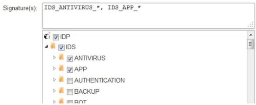
Figure 7.1. IDP Signature Selection
There is a choice of either entering signatures in the upper text box or selecting them through the signature tree underneath. The tree collects the signatures together into their respective groups. and subgroups. When a group of signatures is selected in the tree, the equivalent wildcard definition will automatically appear in the box above. Individual signatures cannot be selected through the tree and can only be entered in the text box.
What appears in the upper text box is equivalent to the way signatures are specified when using the CLI.
Note that all current IDP signatures are listed with their type membership and groupings at:
http://security.dlink.com.tw
Advisories can be found under the "NetDefend IDS" option in the "NetDefend Live" menu.
The structure of the IDP signature hierarchy is explained further in Section 7.6.3, "IDP Signatures and Signature Groups".
HTTP Normalization
Each IDP rule has a section of settings for HTTP normalization. This allows the administrator to choose the actions that should be taken when IDP finds inconsistencies in the URIs embedded in incoming HTTP requests. Some server attacks are based on creating URIs with sequences that can exploit possible weaknesses in HTTP server software.
The URI conditions which IDP can detect are the following:
- Invalid UTF8
This looks for any invalid UTF8 characters in a URI.
- Invalid hex encoding
A valid hex sequence is where a percentage sign is followed by two hexadecimal values to represent a single byte of data. An invalid hex sequence would be percentage sign followed by something which is not a valid hexadecimal value.
- Double encoding
This looks for any hex sequence which itself is encoded using other hex escape sequences. An example would be the original sequence %2526 where %25 is then might be decoded by the HTTP server to '%' and results in the sequence '%26'. This is then finally decoded to '&'.
Initial IDP Packet Processing
The initial order of packet processing with IDP is as follows:
- A packet arrives at the firewall and NetDefendOS performs normal verification. If the packet is part of a new connection then it is checked against the IP rule set before being passed to the IDP subsystem. If the packet is part of an existing connection it is passed straight to the IDP system. If the packet is not part of an existing connection or is rejected by the IP rule set then it is dropped.
- The source and destination information of the packet is compared to the set of IDP Rules defined by the administrator. If a match is found, it is passed on to the next level of IDP processing which is pattern matching, described in step below. If there is no match against an IDP rule then the packet is accepted and the IDP system takes no further actions although further actions defined in the IP rule set are applied such as address translation and logging.
7.6.3. IDP Signatures and Signature Groups
IDP Signatures
In order for IDP to correctly identify an attack, it uses a profile of indicators, or pattern, associated with different types of attack. These predefined patterns, also known as signatures, are stored in a local NetDefendOS database and are used by the IDP subsystem to analyze traffic for attack patterns. Each IDP signature is designated by a unique number.
Consider the following simple attack example involving an exchange with an FTP server. A rogue user might try to retrieve the password file "passwd" from an FTP server using the FTP command RETR passwd. A signature looking for the ASCII text strings RETR and passwd would find a match in this case, indicating a possible attack. In this example, the pattern is found in plaintext but pattern matching is done in the same way on pure binary data.
Recognizing Unknown Threats
Attackers who build new intrusions often reuse older code. This means their new attacks can appear in circulation quickly. To counter this, D-Link IDP uses an approach where NetDefendOS scans for these reusable components, with pattern matching looking for building blocks rather than a completed program. This means that known threats as well as new, previously unknown threats, built with the same reusable components, can be protected against.
Signature Advisories Can Be Searched Online
An advisory is an explanatory textual description of a signature. Reading a signature's advisory will explain to the administrator what the signature will search for. Due to the changing nature of the signature database, advisories are not included in D-Link documentation but instead, are available on the D-Link website.
Note that all current IDP signatures are listed with their type membership and groupings at:
http://security.dlink.com.tw
Advisories can be found under the "NetDefend IDS" option in the "NetDefend Live" menu.
Signature groups, subgroups and more about the signature hierarchy are discussed next.
Signature Groups
Usually, several lines of attacks exist for a specific protocol, and it is best to search for all of them at the same time when analyzing network traffic. To do this, signatures related to a particular protocol are grouped together. For example, all signatures that refer to the FTP protocol form a group. It is best to specify a group that relates to the traffic being searched than be concerned about individual signatures. For performance purposes, the aim should be to have NetDefendOS search data using the least possible number of signatures.
Specifying Signature Groups
IDP Signature Groups fall into a three level hierarchical structure with the following naming form:
Type_Group_Subgroup
The top level of this hierarchy is the signature Type, the second level the Category and the third level the Sub-Category. The signature group called POLICY_DB_MSSQL illustrates this principle where Policy is the Type, DB is the Category and MSSQL is the Sub-Category.
1. The Signature Type
The signature type can be one of the following values:
• IPS
Intrusion Protection Signatures (IPS) are highly accurate and a match is almost certainly an indicator of a threat. Using the Protect action is recommended. These signatures can detect administrative actions and security scanners.
• IDS
Intrusion Detection Signatures (IDS) can detect events that may be intrusions. They have lower accuracy than IPS and may give some false positives so it is recommended that the Audit action is always used. Using them with Protect may interrupt normal traffic.
• POLICY
Policy Signatures detect different types of application traffic. They can be used to block certain applications such as file sharing applications and instant messaging.
2. The Signature Group
This second level is the group name which describes the type of application or protocol. Examples are:
• ICMP
• DNS
• FTP
- HTTP
• SMTP
• P2P
3. The Signature Subgroup
The third level of naming further specifies the target of the group and often specifies the application, for example MSSQL. The Subgroup may not be necessary if the Type and Group are sufficient to specify the set of signatures, for example APP_ITUNES.
The Appendix Listing of IDP Groups
A listing of IDP groupings can be found in Appendix B, IDP Signature Groups. The appendix lists all the signature groupings using the Group name followed by the Subgroup name. The Type could be one of more of IDS, IPS or POLICY so this is not included in the listing.
Processing Multiple IDP Rule Actions
For any IDP Rule object, it is possible to add one or more IDP Rule Action objects as children of the IDP rule. The signatures of each IDP Rule Action are then all applied in turn to the targeted traffic in a top-down ordering. When a match triggers, the action of the triggering IDP Rule Action object is applied.
A signature at a higher position in the IPD Rule Action list will have precedence over another occurrence of the same signature lower down in the list. In other words, only the action associated with a signature's first occurrence in the IPD Rule Action list is performed. This makes it possible to exclude individual signatures from a group by specifying them in a higher IDP Rule Action with the Action property set to ignore. Setting this up is illustrated in Example 7.6, "Setting up IDP for a Mail Server".
IDP Signature Wildcarding
When selecting IDP signature groups, it is possible to use wildcarding to select more than one group. The "?" character can be used to wildcard for a single character in a group name. Alternatively, the "*" character can be used to wildcard for any set of characters of any length in a group name.

Caution: Use the minimum IDP signatures necessary
Use only the minimum of IDP signatures and/or groups necessary. Groups can contain large numbers of signatures and should be used with caution. Sometimes, only a few specific signatures may be needed to defend against the most current and serious threats.
IDP traffic scanning creates an additional processing load on the firewall. Depending on the underlying hardware platform, this should not noticeably degrade performance. However, using too many IDP signatures will adversely affect throughput. Using all the IDP signatures at once should never be attempted.
7.6.4. Insertion/Evasion Attack Prevention
Overview
When defining an IDP Rule object, the administrator can enable or disable the option Protect against insertion/evasion attacks (it is enabled by default). An insertion/evasion attack is a form of attack which is specifically aimed at evading IDP mechanisms. It exploits the fact that in a TCP/IP data transfer, the data stream must often be reassembled from smaller pieces of data because the individual pieces either arrive in the wrong order or are fragmented in some way. Insertions or evasions are designed to exploit this reassembly process.
Insertion Attacks
An insertion attack consists of inserting data into a stream so that the resulting sequence of data packets is accepted by the IDP subsystem but will be rejected by the targeted application. This results is two different streams of data.
As an example, consider a data stream broken up into 4 packets: p1, p2, p3 and p4. The attacker might first send packets p1 and p4 to the targeted application. These will be held by both the IDP subsystem and the application until packets p2 and p3 arrive so that reassembly can be done. The attacker now deliberately sends two packets, p2' and p3', which will be rejected by the application but accepted by the IDP system. The IDP system is now able to complete reassembly of the packets and believes it has the full data stream. The attacker now sends two further packets, p2 and p3, which will be accepted by the application which can now complete reassembly but resulting in a different data stream to that seen by the IDP subsystem.
Evasion Attacks
An evasion attack has a similar end-result to the insertion Attack in that it also generates two different data streams, one that the IDP subsystem sees and one that the target application sees, but it is achieved in the reverse way. It consists of sending data packets that are rejected by the IDP subsystem but are acceptable to the target application.
Detection Action
If an insertion or evasion attack is detected with the Insertion/Evasion Protect option enabled, NetDefendOS automatically corrects the data stream by removing the extraneous data associated with the attack.
Insertion/Evasion Log Events
The insertion/evasion attack subsystem in NetDefendOS can generate two types of log message:
• An Attack Detected log message, indicating an attack has been identified and prevented.
- An Unable to Detect log message when NetDefendOS has been unable to identify potential attacks when reassembling a TCP/IP stream although such an attack may have been present. This condition is caused by infrequent and unusually complex patterns of data in the stream.
Insertion/Evasion Protection is Recommended
By default, insertion/evasion protection is enabled for all IDP rules and this is the recommended setting for most configurations. There are two motivations for disabling the option:
- Increasing throughput - Where the highest throughout possible is desirable, then turning the option off, can provide a slight increase in processing speed.
- Excessive False Positives - If there is evidence of an unusually high level of insertion/evasion false positives then disabling the option may be prudent while the false positive causes are investigated.
7.6.5. Setting Up IDP
The steps for setting up IDP are as follows:
• Create an IDP Rule object which identifies the traffic to be processed.
- Add one or more child IDP Rule Action objects to the rule which each specify:
i. The IDP signatures used for scanning the traffic. These can consist of one or more single signatures and/or groups with wildcarding possible.
ii. The action to take when a signature triggers. This can be to drop the connection with a log message generated, or to just log that the action triggered, or to ignore the trigger (the latter is useful for excluding signatures from actions lower in the action list).
iii. Choose to blacklist source IPs that caused IDP to trigger. This is explained next.
IDP Dynamic Blacklisting
Specifying the Protect option in an IP Rule Action object includes the additional option that the source IP address that triggered the IDP Rule Action is added to the firewall's Blacklist. This means that all subsequent traffic (optionally just with the same protocol) coming from blacklisted source IPs will be automatically dropped by NetDefendOS.
The following properties exist in the IDP Rule Action object to control dynamic blacklisting if blacklisting is enabled.
- Block duration
The duration of the block in seconds. If not specified (the default) it will be indefinite, or until the next system restart.
- Block service
The block of the source IP address will only apply to traffic from that address with the protocol that triggered the block. Traffic with a different protocol will not be affected. This is disabled by default.
- Ignore established
When a block is triggered by a source IP address then existing connections from that IP address will not be affected. This is disabled by default.

Tip: Whitelist the management IP addresses
Any IP address that exists in the NetDefendOS whitelist cannot be blacklisted. For this reason it is recommended that the IP address of the firewall management computer and the D-Link firewall itself is added to the whitelist so they cannot be blocked by IDP.
For more details of how blacklisting functions see Section 7.8, "Blacklisting Hosts and Networks".
Example 7.6. Setting up IDP for a Mail Server
The following example details the steps needed to set up IDP for a simple scenario where a mail server is exposed to the Internet on the DMZ network with a public IPv4 address. The Internet can be reached through the firewall on the WAN interface as illustrated below.
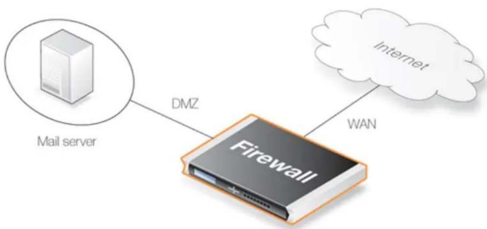
flowchart
graph TD
A["Mail server"] -->|DMZ| B["Firewall"]
B -->|WAN| C["Internet"]
An IDP rule called IDPMailSrvRule will be created, and the Service object to use is the SMTP service. The Source Interface and Source Network defines where traffic is coming from, in this example the external network. The Destination Interface and Destination Network define where traffic is directed to, in this case the mail server. The Destination Network should therefore be set to the object defining the mail server.
The IDP signature group called IPS_SMTP_* will be used but the specific signatures for SMTP overflow exploits (72828, 72829, 58183 and 52543) will be excluded from the group by first adding a separate IDP Rule Action.
In addition, if a new connection triggers a Protect action then the source IP address will be blacklisted with a block time of 3600 seconds.
Command-Line Interface
Create an IDP Rule for the targeted traffic:
gw-world:/> add IDPRule SourceInterface=wan
SourceNetwork=wannet
DestinationInterface=dmz
DestinationNetwork=ip_mailserver
Service=smtp
Name=IDPMailSrvRule
Change the CLI context to be the rule:
gw-world:/> cc IDPRule IDPMailSrvRule
gw-world:/IDPMailSrvRule>
First, add the signatures to be excluded from the IPS_SMTP group:
gw-world:/IDPMailSrvRule> add IDPRuleAction
Action=Ignore
Signatures=72828,72829,58183,52543
Add scanning with the IPS_SMTP group signatures:
gw-world:/IDPMailSrvRule> add IDPRuleAction
Action=Protect
Signatures=IPS_SMTP_*
Blacklist=Yes
BlackListTimeToBlock=36000
Web Interface
Create an IDP Rule for the targeted traffic:
1. Go to: Policies > Intrusion Prevention > IDP Rules > Add > IDP Rule
2. Now enter:
• Name: IDPMailSrvRule
• Service:smtp
3. Under Address Filter enter:
• Source Interface: wan
• Source Network: wannet
• Destination Interface: dmz
• Destination Network: ip_mailserver
First, add the signatures to be excluded from the IPS_SMTP group:
1. Select Rule Actions for the IDP rule:
2. Select: Add > IDP Rule Action
3. Now enter:
• Action: Ignore
• Signatures: 72828,72829,58183,52
4. Click OK
Add scanning with the IPS\_SMTP group signatures:
-
Again select: Add > IDP Rule Action
-
Now enter:
• Action: Protect
• Signatures: IPS_SMTP_*
• Dynamic Blacklisting: Enable
- Block duration: 3600
3. Click OK
Finally, click OK to save the rule and its actions.
7.6.6. SMTP Log Receiver for IDP Events
In order to receive notifications via email of IDP events, a SMTP Log receiver can be configured. This email will contain a summary of IDP events that have occurred in a user-configurable period of time.
When an IDP event occurs, the NetDefendOS will wait for Hold Time seconds before sending the notification email. However, the email will only be sent if the number of events occurred in this period of time is equal to, or bigger than the Log Threshold. When this email has been sent, NetDefendOS will wait for Minimum Repeat Time seconds before sending a new email.
The IP Address of SMTP Log Receivers is Required
When specifying an SMTP log receiver, the IP address of the receiver must be specified. A domain name such as dns:smtp.example.com cannot be used.
Example 7.7. Configuring an SMTP Log Receiver
In this example, a existing IDP Rule object called exemplerule is configured with an SMTP2c log receiver. Once an IDP event occurs, the rule is triggered. At least one new event occurs within the hold time of 120 seconds, thus reaching the log threshold level (at least 2 events have occurred). This results in an email being sent containing a summary of the IDP events. Several more IDP events may occur after this, but to prevent flooding the mail server, NetDefendOS will wait 600 seconds (equivalent to 10 minutes) before sending a new email.
An SMTP2c server is assumed to have already been configured in the address book with the name smtp-server.
Command-Line Interface
Add an SMTP2c log receiver:
gw-world:/> add LogReceiver LogReceiverSMTP smt4IDP
IPAddress=smtp-server
Receiver1=youremail@example.com
Next, change the CLI context to be IDPRule:
gw-world:/> cc IDPRule exemplerule
Now, set the property of the first IDPRuleAction:
gw-world:/examplerule> set IDPRuleAction 1 LogEnabled=Yes
Return to the default CLI context:
gw-world:/> cc
Web Interface
Adding an SMTP2c log receiver:
-
Go to: System > Device > Event Receivers > Add > SMTP2c Event Receiver
-
Now enter:
- Name: smtp4IDP
- SMTP Server: smtp-server
- Server Port: 25
• Specify alternative email addresses (up to 3)
- Sender: hostmaster
• Subject: Log event from NetDefendOS
• Minimum Repeat Delay: 600
- Hold Time: 120
- Log Threshold: 2
- Click OK
IDP Rules:
-
Go to: Policies > Intrusion Prevention > IDP Rules > Add > IDP Rule
-
Select the rule exemplerule
-
Enable the Enable logging option
-
Click OK
7.6.7. Best Practice Deployment
IDP Deployment Recommendations
The following are the recommendations for IDP employment:
- Enable only the IDP signatures for the traffic that is being allowed. For example, if the IP rule set is only allowing HTTP traffic then there is no point enabling FTP signatures.
- Once the relevant signatures are selected for IDP processing, the IDP system should always be initially run in Audit mode.
- After running IDP in Audit mode for a sample period with live traffic, examines the log messages generated. Check for the following:
i. When IDP triggers, what kind of traffic is it triggering on?
ii. Is the correct traffic being identified?
iii. Are there any false positives with the signatures that have been chosen?
- Adjust the signature selection and examine the logs again. There may be several adjustments before the logs demonstrate that the desired effect is being achieved.
If certain signatures are repeatedly triggering it may be reason to look more closely to check if a server is under attack.
- After a few days running in Audit mode with satisfactory results showing in the logs, switch over IDP to Protect mode so that triggering connection are dropped by NetDefendOS. However, IDS signatures are best kept in Audit mode as they can interrupt normal traffic flows because of false positives.
- If required, enable the blacklisting feature of IDP so that the source IP for triggering traffic is blocked. This is a powerful feature of IDP and useful when dealing with an application like BitTorrent.
IDP Database Updating
The IDP signature database can be updated automatically and certain signatures can be dropped or updated and new signatures introduced. In some cases, it can be preferable to force the database update manually so that the effect of any changes can be observed following the update.
Automatic updates might take place without the necessary checking in place to make sure there are no disruptions to live traffic.
7.7. Threshold Rules
Overview
A Threshold Rule configuration object provides a means of detecting excessive connection activity, as well as reacting to it. An example of such abnormal activity might be an infected internal opening repeated connections to external IP addresses. Alternatively, an external computer might try opening excessive numbers of connections to a website's public IP address. Note that the term "connection" in this context refers to all types of connections tracked by the NetDefendOS state engine, such as TCP, UDP or ICMP.

Note: Threshold rules are not available on all NetDefend models
The threshold rules feature is not available on the DFL-260E.
Threshold Actions
A threshold rule is like other security rules found in NetDefendOS. A filtering combination of source/destination network/interface can be specified along with a service, such as HTTP. Each Threshold Rule object can have one or more Threshold Action objects added to it as children and these actions specify the triggering threshold quantities and what to do when the quantity is exceeded.
A Threshold Action object has the following key properties:
• Action
This is the response of the rule when the limit is exceeded. Either the option Audit or Protect can be selected. These options are explained in more detail below.
- Group By
The rule can be either Host or Network based. These options are explained below.
- Threshold
This is the numerical limit which must be exceeded for the action to be triggered.
- Threshold Type
A rule can be specified to either limit the number of connections per second or limit the total number of concurrent connections.
Connection rate Limiting allows an administrator to put a limit on the number of new connections being opened per second.
Total connection limiting allows the administrator to put a limit on the total number of connections opened. This function is extremely useful when NAT pools are used since peer-to-peer applications can require large numbers of connections.
The Group By Setting
The two groupings allowed for this property are the following:
- Host Based
The threshold is applied separately to connections from different IP addresses.
- Network Based
The threshold is applied to all connections matching the rules as a group.
Rule Actions
When a Threshold Rule is triggered, one of two responses is possible:
• Audit
Leave the connection intact but log the event.
- Protect
Drop the triggering connection.
Logging would be the preferred option if the appropriate triggering value cannot be determined beforehand. Multiple actions for a given rule might consist of Audit for a given threshold while the action might become Protect for a higher threshold.
Multiple Triggered Actions
When a rule is triggered then NetDefendOS will perform the associated rule actions that match the condition that has occurred. If more than one action matches the condition then those matching actions are applied in the order they appear in the user interface.
If several actions that have the same combination of Type and Grouping (see above for the definition of these terms) are triggered at the same time, only the action with the highest threshold value will be logged.
Exempted Connections
It should be noted that some advanced settings, known as Before Rules settings, can exempt certain types of connections for remote management from examination by the NetDefendOS IP rule set if they are enabled. These Before Rules settings will also exempt the connections from threshold rules if they are enabled.
Threshold Rules and ZoneDefense
Threshold rules are used in the D-Link ZoneDefense feature to block the source of excessive connection attempts from internal hosts. More information on this feature can be found in Section 7.9, "ZoneDefense".
Threshold Rule Blacklisting
If the Protect option is used, Threshold rules can be configured so that the source that triggered the rule, is added automatically to a Blacklist of IP addresses or networks. If several Protect actions with blacklisting enabled are triggered at the same time, only the first triggered blacklisting action will be executed by NetDefendOS.
A host based action with blacklisting enabled will blacklist a single host when triggered. A network based action with blacklisting enabled will blacklist the source network associated with
the rule. If the Threshold Rule is linked to a service then it is possible to block only that service.
When blacklisting is selected, the administrator can choose to leave pre-existing connections from the triggering source unaffected, or can alternatively choose to have the connections dropped by NetDefendOS. The length of time, in seconds, for which the source is blacklisted can also be set.
Example 7.8. Creating a Threshold Rule
This example considers the case of HTTP connection requests destined for an internal web server, arriving at the wan interface. A Threshold Rule object will be created that will drop all connections from a single source IP if the total new connection rate from the IP exceeds 100 per second.
In addition, after the threshold rule is triggered, all HTTP traffic from the triggering source IP will be blacklisted for 5 minutes (300 seconds).
Here, it is assumed that a SAT rule also exists which translates the destination address of wan_ip to the IP address of the protected webserver. The SAT rule definition is not described in the example.
Command-Line Interface
First create the threshold rule:
gw-world:/> add ThresholdRule
SourceInterface=wan
SourceNetwork=all-nets
DestinationInterface=core
DestinationNetwork=wan_ip
Service=http-all
Name=limit_dmz
Next, change the context to be the new rule and add a threshold action to it:
gw-world:/> cc ThresholdRule limit_dmz
gw-world:/1(limit_dmz)> add ThresholdAction
Threshold=100
ThresholdUnit=Conns
Action=Protect
GroupBy=SourceIP
BlackList=Yes
BlackListBlockOnlyService=Yes
BlackListTimeToBlock=300
BlackListIgnoreEstablished=No
Web Interface
First create the threshold rule:
-
Go to: Threat Prevention > Threshold Rules > Add > Threshold Rule
-
Now enter:
-
Name: limit_dmz
• Service: http-all
- Source Interface: wan
- Source Network: all_nets
- Destination Interface: core
- Destination Network: wan_ip
Next, add the threshold action to the rule:
-
Select Threshold Action
-
Select Add > Threshold Action
-
Now enter:
• Action: Protect
- Group by: Host based
- Enable Blacklist
• Time to block: 300
- Enable Block only service
- Disable Ignore Established
- Click OK
7.8. Blacklisting Hosts and Networks
Overview
NetDefendOS implements a blacklist of host or network IPv4 addresses which can be utilized to protect against traffic coming from specific Internet sources. If NetDefendOS receives an attempt to open a connection from a blacklisted IPv4 address then the connection is dropped with the option to generate a log event message. In addition, NetDefendOS has a whitelist which can contain IPv4 addresses that will never be blacklisted.
Note that for automatically added blacklist entries (for example, from IDP) NetDefendOS only checks the source IP of incoming connections against the blacklist. However, it is possible to manually add an entry with the blacklist CLI command which checks the destination IP address instead.

Note: Restarting should not greatly affect the lists
Most of the contents of the blacklist and whitelist should not be lost if the firewall restarts. NetDefendOS makes a copy of the both lists in non-volatile memory every 2 hours in order not to put unnecessary load on the firewall's CPU. Therefore, at most, the last two hours of changes might be lost.
Synchronization in a High Availability (HA) Cluster
There is no synchronization of the NetDefendOS blacklist between the peers in an HA cluster. This means that after an HA failover the previous contents of the blacklist is no longer available. The expectation is that the external IP addresses that had caused the old blacklist entries to be added will do so again if they are still triggering the relevant features such as IDP and threshold rules.
However, the same is not true of the whitelist. The whitelist is a static list that is synchronized between the devices in an HA cluster. It's contents are preserved after a failover.
Methods of Blacklist Addition
Certain NetDefendOS subsystems have the ability to optionally blacklist a host or network when certain conditions are encountered. Blacklist entries can also be added (and deleted) manually. These subsystems and methods for adding to the blacklist are the following:
- Addition when an Intrusion Detection and Prevention (IDP) rule is triggered.
- Addition when a threshold rule triggers. (Available on certain NetDefend models only - see Section 7.7, "Threshold Rules" for details.)
- Addition when Botnet Protection or DoS Protection or Scanner Protection triggers.
• Manual addition using the CLI blacklist command.
- Addition from a separate remote computer using the REST API. Doing this is described in the separate NetDefendOS REST API Guide.
Blacklist Entry Data Fields
The following are the important data fields stored with each blacklist entry:
- Host - The source IPv4 address that is to be blocked.
- Destination - This is an optional IP address so that the destination address of a new connection must also match this value for the connection to be dropped.
- Service - The Service object of the rule that added the entry. As explained later, multiple entries can have the same blacklisted IPv4 address but different services.
- Port - This can be optionally be used instead of the Service value to drop connections to a specific port number at the Host address.
• Time to Live - How long the entry will remain in the blacklist in seconds.
- Alert Type - This is indicates the NetDefendOS subsystem that created the entry or if it was created manually with the CLI or REST API. All the alert types are listed in the blacklist command section of the separate CLI Reference Guide.
- Rule Name
This is the name of the rule object in the configuration that added the blacklist entry. If it was added manually with the CLI or REST API then this is just an arbitrary text string that does not indicate an object name.
There are other pieces of data stored in the blacklist but the above lists the fields that are most relevant to understanding how the feature works.
Entries Have Unique IP Address and Service Combinations
Each blacklist entry has a Service object reference associated with it and each entry has a unique combination of IPv4 address and Service. The service is determined by the Service property of the triggering rule that created the entry.
For example, the blacklist entry for the IPv4 address 203.0.113.1 and service http-all is distinct from the entry with the IPv4 address 203.113.10 and service ftp-inbound. They can be created separately and they can be deleted separately. If the service for an entry is all_services then any connection originating from the IP address is dropped, regardless of the service.
Note that when adding a blacklist entry manually, a specific port number can be specified with the IP address instead of a service.
Blacklisting Options for IDP Rules and Threshold Rules
The automatic blacklisting of a host or network can be enabled in an IDP rule or a threshold rule by specifying the Protect action. The following blacklist options can then be set with this action:
• Time to Block Host/Network in seconds
The host or network which is the source of the traffic will stay on the blacklist for the specified time and then be removed. If the same source triggers another entry to the blacklist then the blocking time is renewed to its original, full value (in other words, it is not cumulative).
- Block only this Service
By default, blacklisting blocks all services for the triggering host.
• Exempt already established connections from Blacklisting
If there are established connections that have the same source as this new Blacklist entry
then they will not be dropped if this option is set.
For further details on usage see Section 7.6.5, "Setting Up IDP" and Section 7.7, "Threshold Rules".
The CLI blacklist Command
The blacklist command can be used to look at as well as manipulate the current contents of the blacklist. It can only be used to display the current whitelist.
The entire current blacklist can be viewed with the command:
gw-world:/> blacklist -show -black
Similarly the entire contents of the white list can be shown:
gw-world:/> blacklist -show -white
This blacklist command can be used to remove a host from the blacklist using the -unblock option. The -block option is used to add a host to the blacklist:
gw-world:/> blacklist -block 203.0.113.1
The -unblock option removes it:
gw-world:/> blacklist -unblock 203.0.113.1
All blacklist command options are described in the separate CLI Reference Guide.
Example 7.9. Blacklisting an IP Network
In this example, the IP4 network 203.0.113.0/24 will be added to the blacklist so that any HTTP or HTTPS connections (matching the service http-all) from this network will be dropped. The blacklist entry will remain in the blacklist for a period of 86,400 seconds (1 day).
Command-Line Interface
gw-world:/> blacklist -block 203.0.113.0/24 -serv=http-all -time=86400
The Blacklist and the Web Interface
The Web Interface does not allow blacklist entries to be added or deleted. However, the Web Interface can be used to monitor blacklist contents by going to Status > Blacklist.
Whitelisting
To ensure that Internet traffic coming from trusted sources, such as the management workstation, are not blacklisted under any circumstances, a Whitelist is also maintained by NetDefendOS. Any IPv4 address object can be added to this whitelisted which means that new connections coming from this address are automatically trusted.

Tip: Important IP addresses should be whitelisted
It is recommended to add the D-Link firewall itself to the whitelist as well as the IP address or network of the management workstation since blacklisting of either could have serious consequences for network operations.
It is also important to understand that although whitelisting prevents a particular source from being blacklisted, it still does not prevent NetDefendOS mechanisms such as threshold rules from dropping or denying connections from that source. What whitelisting does is prevent a source being added to a blacklist if that is the action a rule has specified.
Adding to the Whitelist
Whitelisting is not done through the blacklist command. Instead, a special Whitelist host (called BlacklistWhiteHost in the CLI) is added to the configuration.
Example 7.10. Adding a Host to the Whitelist
In this example we will add an IP address object called white_ip to the whitelist. This will mean this IP address can never be blacklisted.
Command-Line Interface
gw-world:/> add BlacklistWhiteHost Addresses=white_ip Service=all_tcp
Web Interface
- Go to: System > Advanced Settings > Whitelist > Add > Whitelist host
- Now select the IP address object white_ip so it is added to the whitelist
- Select the service all_tcp to be associated with this whitelist entry
- Click OK
7.9. ZoneDefense
ZoneDefense Blocks Hosts or Networks Using Switches
ZoneDefense is a feature that can be used as a counter-measure to stop a threat-infected computer in a local network from infecting other computers.
When hosts or clients in a network become infected with a virus or another form of threat, this can often show its presence through anomalous behavior, such as large numbers of new connections being opened to outside hosts. With the ZoneDefense feature, NetDefendOS can automatically instruct a D-Link switch to block access to a host or network when such unusual behavior is detected.
The ZoneDefense feature will only function with switches manufactured by D-Link and a list of the supported switches is given later in this section.

Note: ZoneDefense is not available on all NetDefend models
The ZoneDefense feature is not available on the DFL-260E.
ZoneDefense Makes Use of SNMP
Simple Network Management Protocol (SNMP) is an application layer protocol for complex network management. SNMP allows the managers and managed devices in a network to communicate with each other.
For ZoneDefense, NetDefendOS uses SNMP to control switch behavior. Management privileges to a switch are gained by NetDefendOS using the configured SNMP Community String for write access. The appropriate Management Information Base (MIB) file is then used by NetDefendOS to determine how commands should be sent to a switch.
All relevant MIB files are already loaded into NetDefendOS but when configuring ZoneDefense, NetDefendOS needs to be told which MIB to use. For older D-Link switches this is done by specifying the exact switch product name. However, newer D-Link switches use a common Universal MIB so the exact switch type need not to be specified.
Threshold Rules Can Trigger ZoneDefense
By setting up a NetDefendOS Threshold Rule, hosts or networks that are exceeding a defined connection threshold can be dynamically blocked using the ZoneDefense feature. Thresholds are based on either the number of new connections made per second, or on the total number of connections being made.
These connections may be made by either a single host or all hosts within a specified CIDR network range (an IP address range specified by a combination of an IP address and its associated network mask). These rules are discussed further in Section 7.7, "Threshold Rules".
Botnet Protection Can Trigger ZoneDefense
The Botnet Protection feature in NetDefendOS can trigger ZoneDefense when the source or destination IP for a connection on any interface is flagged as being associated with a botnet by the IP reputation subsystem. This feature is described further in Section 7.3, "Botnet Protection".
Blocking Uses ACL Uploads
When NetDefendOS detects that a host or a network has reached the specified threshold limit, it uploads Access Control List (ACL) rules to the relevant switch and this blocks all traffic for the host or network displaying the unusual behavior. Blocked hosts and networks remain blocked until the system administrator manually unblocks them using the Web or Command Line interface.
Supported D-Link Switches
Every switch that is to be controlled by the firewall has to be manually specified in the NetDefendOS configuration.
The information that must be specified in the configuration setup in order to control a switch includes:
• The IP address of the management interface of the switch.
• The switch model type (or Universal MIB for newer switches).
• The SNMP community string for write access to the switch.
ZoneDefense supports all newer D-Link switches which use the Universal MIB. The following is a list of supported switches:
• DXS-1210 A1 R1.00 and later.
• DXS-1100 A1 R1.00 and later
• DXS-3600 R2.32 and later.
• DXS-3400 R1.00 and later.
• DGS-1100-16/18/24/26/24P B1/B2 R1.00 and later.
• DGS-1100-16/ME, 18/ME, 24/ME, 26/ME, 24P/ME B1/B2 R1.00 and later.
• DGS-1100 MP/MPP B1 R1.00 and later.
• DGS-1210 C1 4.00 and later.
• DGS-1210 E1 5.00 and later.
• DGS-1210 F1 R6.00 and later.
• DGS-1210 G1 R7.00 and later.
• DES-1210 C1 4.00 and later.
• DES-1210-52/ME B R20.03 and later.
• DGS-1210/ME A1 6.12 and later.
• DGS-1210/ME B1 R7.00 and later.
• DGS-1510 R1.00 and later.
• DGS-1510/ME R1.00 and later.
• DGS-3000 A1 R1.00 and later.
• DGS-3000 A2 R2.00 and later.
• DGS-3000 B1 R3.00 and later.
• DGS-3420 R1.00 and later.
• DGS-3620 R1.00 and later.
• DGS-3630 R.00 and later.

Tip: Switch firmware versions should be the latest
It is advisable when using ZoneDefense to make sure that all switches have the latest firmware version installed.
Using Threshold Rules
A threshold rule will trigger ZoneDefense to block out a specific host or a network if the connection limit specified in the threshold rule is exceeded. The triggering limit can be one of two types:
- Connection Rate Limit
This can be triggered if the rate of new connections per second to the firewall exceeds a specified threshold.
• Total Connections Limit
This can be triggered if the total number of connections to the firewall exceeds a specified threshold.
Threshold rules have a traffic filter which are similar to other NetDefendOS rules. This filter specifies what type of traffic a threshold rule applies to.
A single threshold rule object has the following properties:
• Source interface and source network.
- Destination interface and destination network.
• Service.
• Type of threshold: Host and/or network based.
Traffic that matches the above criteria and causes the host/network threshold to be exceeded will trigger the ZoneDefense feature. This will prevent the host/networks from accessing the switch(es). All blocking in response to threshold violations will be based on the IP address of the host or network on the switch(es). When a network-based threshold has been exceeded, the source network will be blocked out instead of just the offending host.
For a detailed discussion of how to specify threshold rules, see Section 7.7, "Threshold Rules".
Manual Blocking and Exclude Lists
As a complement to threshold rules, it is also possible to manually define hosts and networks that are to be statically blocked or excluded. Manually blocked hosts and networks can be blocked by default or based on a schedule. It is also possible to specify which protocols and protocol port numbers are to be blocked.
Exclude Lists can be created and used to exclude hosts from being blocked when a threshold rule limit is reached. Good practice includes adding to the list the firewall's interface IP or MAC address connecting towards the ZoneDefense switch. This prevents the firewall from being accidentally blocked out.
Example 7.11. Setting Up ZoneDefense
This example illustrates ZoneDefense setup where a host on a switch is blocked because a threshold rule for HTTP traffic triggers. It is assumed that all interfaces on the D-Link firewall have already been configured as shown below.
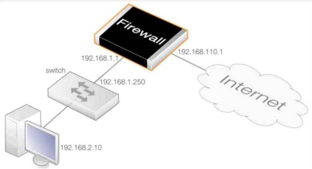
flowchart
graph TD
A["Firewall"] -->|192.168.1.1| B["switch"]
A -->|192.168.110.1| C["Internet"]
B -->|192.168.2.10| D["Computer"]
An HTTP threshold of 10 connections/second is to be applied to traffic. If the connection rate exceeds this, NetDefendOS will instruct the switch to block the host (within the network range 192.168.2.0/24).
A D-Link switch of model type DES-3226S is assumed, with a management interface address of 192.168.1.250 and it is connected to a firewall interface with address 192.168.1.1. This interface will be added into the exclude list to prevent the firewall itself from being accidentally blocked by the switch.
Web Interface
Add a new switch into ZoneDefense section:
-
Go to: Threat Prevention > ZoneDefense > Switches
-
Select Add > ZoneDefense Switch
-
Now enter:
- Name: switch1
- Switch model: DES-3226S
• IP Address: 192.168.1.250
4. For the SNMP Community field enter the Write Community String value configured for the switch.
5. Click Check Switch to verify that the firewall can communicate with the switch and the community string is correct.
6. Click OK
Add the firewall's management interface into the exclude list:
- Go to: Threat Prevention > ZoneDefense > Exclude list
- For Addresses choose the object name of the firewall's interface address 192.168.1.1 from the Available list and put it into the Selected list.
- Click OK
Configure an HTTP threshold of 10 connections/second:
- Go to: Threat Prevention > Threshold Rules > Add > Threshold Rule
- For the Threshold Rule enter:
• Name: HTTP-Threshold
• Service: http
- For Address Filter enter:
• Source Interface: Enter the firewall's management interface
- Destination Interface: any
• Source Network: 192.168.2.0/24 (or the address object name)
- Destination Network: all-nets
- Click OK
Specify the threshold, the threshold type and the action to take if exceeded:
- Go to: Add > Threshold Action
- Configure the Threshold Action as follows:
• Action: Protect
- Group By: Host-based
• Threshold: 10
- Set the units for the threshold value to be Connections/Second
• Tick the Use ZoneDefense checkbox - Click OK
ZoneDefense with Anti-Virus Scanning
ZoneDefense can also be used in conjunction with the NetDefendOS Anti-Virus scanning feature. NetDefendOS can first identify a virus source through antivirus scanning and then block the source by communicating with switches configured to work with ZoneDefense.
This feature can be activated via the following ALGs:
- HTTP - ZoneDefense can block an HTTP server that is a virus source.
- FTP - ZoneDefense can block a local FTP client that is uploading viruses.
- SMTP - ZoneDefense can block a local SMTP client that is sending viruses with emails.
Anti-virus scanning with ZoneDefense is discussed further in Section 6.4.4, "Anti-Virus with ZoneDefense" and in the sections covering the individual ALGs. Configuring ZoneDefense with anti-virus scanning can be done with IP Policy objects by enabling it in a Anti-Virus Profile object that is then associated with a policy.
ZoneDefense Limitations
There are some differences in ZoneDefense operation depending on the switch model:
- The first difference is the latency between the triggering of a blocking rule to the moment when a switch actually starts blocking out the traffic matched by the rule. All switch models require a short period of latency time to implement blocking once the rule is triggered. Some models can activate blocking in less than a second while some models may require a minute or more.
- A second difference is the maximum number of rules supported by different switches. Some switches support a maximum of 50 rules while others support up to 800 (usually, in order to block a host or network, one rule per switch port is needed). When this limit has been reached no more hosts or networks will be blocked out.

Important: Clearing the ACL rule set on the switch
ZoneDefense uses a range in the ACL rule set on the switch. To avoid potential conflicts in these rules and guarantee the firewall's access control, it is strongly recommended that the administrator clear the entire ACL rule set on the switch before performing the ZoneDefense setup.
Chapter 8: Address Translation
This chapter describes NetDefendOS address translation capabilities.
• Overview, page 666
• NAT, page 668
• NAT Pools, page 675
• SAT, page 679
• Automatic Translation, page 705
8.1. Overview
The ability of NetDefendOS to change the IP address of packets as they pass through the D-Link firewall is known as address translation.
The ability to transform one IP address to another can have many benefits. Two of the most important are:
- Private IPv4 addresses can be used on a protected network where protected hosts need to have access to the Internet. There may also be servers with private IPv4 addresses that need to be accessible from the Internet.
- Security is increased by making it more difficult for intruders to understand the topology of the protected network. Address translation hides internal IP addresses which means that an attack coming from the "outside" is more difficult.
Types of Translation
NetDefendOS supports two types of translation:
• Dynamic Network Address Translation (NAT)
• Static Address Translation (SAT)
Application of both types of translation depend on the specified security policies, which means that they are applied to specific traffic based on filtering rules that define combinations of
source/destination network/interface as well as service. Two types of NetDefendOS IP rules, NAT rules and SAT rules are used to configure address translation.
This section describes and provides examples of configuring NAT and SAT rules.
8.2. NAT
Dynamic Network Address Translation (NAT) provides a mechanism for translating original source IP addresses to a different address. Outgoing packets then appear to come from a different IP address and incoming packets back to that address have their IP address translated back to the original IP address.
Methods of Configuring NAT in NetDefendOS
There are two ways of configuring NAT in the NetDefendOS IP rule set:
- Using IP Policies
An IP Policy object can be added to the IP rule set with its Source Address Translation property set to NAT. This is the recommended method and makes it simpler to add other security mechanisms on the same IP rule set entry.
An alternative to setting the Source Translation property of an IP policy to NAT is to leave it at the default value of Auto. What this will do is perform NAT translation automatically if the source IPs are private addresses and the destination IPs are public addresses. The Auto option will not be discussed further in this section but a detailed description can be found in Section 8.5, "Automatic Translation".
- Using IP Rules
An IP Rule object can be added to the IP rule set with its Action property set to NAT. This method can be useful for compatibility with older NetDefendOS versions but does not provide any advantages over using an IP policy.
Examples of both these methods are included in this section.
NAT Benefits
NAT can have two important benefits:
- The IP addresses of individual clients and hosts can be "hidden" behind the firewall's IP address.
- Only the firewall needs a public IPv4 address for Internet access. Hosts and networks behind the firewall can be allocated private IPv4 addresses but can still have access to the Internet through the public IPv4 address.
- In a Internet where there are ever fewer public IPv4 addresses available, NAT provides a way to multiplex multiple connections over a single IPv4 address. This is important at the enterprise level but also at the ISP level where two levels of NAT can be used to enable Carrier Grade NAT (CG-NAT).
NAT Provides many-to-one IP Address Translation
NAT provides many-to-one translation. This means that each NATing IP rule set entry can translate between several source IP addresses and a single source IP address.
To maintain session state information, each connection from dynamically translated addresses uses a unique port number and IP address combination as its sender. NetDefendOS performs automatic translation of the source port number as well as the IP address. In other words, the source IP addresses for connections are all translated to the same IP address and the connections
are distinguished from one another by the allocation of a unique port number to each connection.
The diagram below illustrates the concept of NAT.
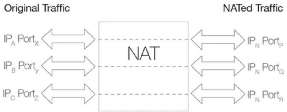
flowchart
graph LR
A["Original Traffic"] --> B["NAT"]
C["NATed Traffic"] --> B
B --> D["IP_A Port_x"]
B --> E["IP_B Port_y"]
B --> F["IP_C Port_z"]
D <--> G["IP_N Port_p"]
E <--> H["IP_N Port_Q"]
F <--> I["IP_N Port_R"]
Figure 8.1. NAT IP Address Translation
In the illustration above, three connections from IP addresses A, B and C are NATed through a single source IP address N. The original port numbers are also changed.
The next source port number allocated for a new NAT connection will be the first free port selected randomly by NetDefendOS. Ports are allocated randomly to increase security.
Limitations on the Number of NAT Connections
Approximately 64,500 simultaneous NAT connections are possible if a "connection" is considered to be a unique pair of IP addresses and different port numbers are not used or the same destination port is used.
However, since there is a possible range of 64,500 source ports and the same number for destination ports, it is theoretically possible to have over 4 billion connections between two IP addresses if all ports are used.
Using NAT Pools Can Increase the Connections
To increase the number of NAT connections that can exist between the D-Link firewall and a particular external host IP, the NetDefendOS NAT pools feature can be used which can automatically make use of additional IP addresses on the firewall.
This is useful in situations where a remote server requires that all connections are to a single port number. In such cases, the 64,500 limit for unique IP address pairs will apply.
See Section 8.3, "NAT Pools" for more information about this topic.
The Source IP Address Used for Translation
There are three options for how NetDefendOS determines the source IP address that will be used for NAT:
• Use the IP Address of the Interface
When a new connection is established, the routing table is consulted to resolve the
outbound interface for the connection. The IP address of that resolved interface is then used as the new source IP address when NetDefendOS performs the address translation. This is the default way that the IP address is determined.
• Specify a Specific IP Address
A specific IP address can be specified as the new source IP address. The specified IP address needs to have a matching ARP Publish entry configured for the outbound interface. Otherwise, the return traffic will not be received by the D-Link firewall. This technique might be used when the source IP is to differ based on the source of the traffic. For example, an ISP that is using NAT, might use different IP addresses for different customers.
• Use an IP Address from a NAT Pool
A NAT Pool, which is a set of IP addresses defined by the administrator, can be used. The next available address from the pool can be used as the IP address used for NAT. There can be one or many NAT pools and a single pool can be used in more than one NAT rule. This topic is discussed further in Section 8.3, "NAT Pools".
The NAT Translation Process
To explain the NAT process in a simple example, consider a protected client behind the firewall which has the private IP address 192.168.1.5. It wants to make an HTTP connection on port 80 of a server with the public IP 203.0.113.10.
The public IP of the NetDefendOS Ethernet interface connected to the Internet is 203.0.113.5 (for simplicity, assume that the interface and the server are on the same network). NAT translation is applied to connections originating on this interface by specifying a NATing IP rule set entry that allows connections from the client to the server.
The sequence of these events in the NAT process is illustrated in the diagram below and the description of steps that follows.
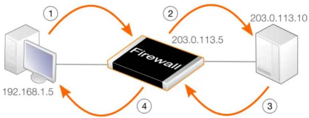
flowchart
graph TD
A["192.168.1.5"] --> B["Firewall"]
B --> C["203.0.113.5"]
C --> D["203.0.113.10"]
D --> E["3"]
E --> F["4"]
F --> A
style A fill:#f9f,stroke:#333
style B fill:#ccf,stroke:#333
style C fill:#cfc,stroke:#333
style D fill:#fcc,stroke:#333
style E fill:#cff,stroke:#333
style F fill:#ffc,stroke:#333
Figure 8.2. The NAT Translation Process
- The sender at IP address 192.168.1.5 sends a packet from a dynamically assigned port number (assume port 1038) to the server at 203.0.113.10 on port 80.
192.168.1.5:1038 => 203.0.113.10:80
- Assume that the IP policy NAT Outgoing Interface IP option is used. NetDefendOS will change the source port to a random unused port on its interface which is above port 1024. In this example, assume port 32,789 is chosen. The packet is then sent to its destination with this source port and the source IP of the interface.
203.0.113.5:32789 => 203.0.113.10:80
- The server then processes the packet and sends its response back to the source IP and port.
203.0.113.10:80 => 203.0.113.5:32789
- NetDefendOS receives the packet and looks up the destination IP and port in its list of open connections. If it finds the connection, it restores the original source IP address and port number and forwards the packet.
203.0.113.5:32789 => 192.168.1.5:1038
- The original sender has now received the response without needing a public IP address of its own.
Example 8.1. Setting Up NAT with an IP Policy
This example adds a NAT IP policy that will perform address translation for all HTTP traffic originating from the internal network lan flowing to the Internet on the wan interface. The IP address of the wan interface will be used as the NATing address for all connections.
Command-Line Interface
gw-world:/> add IPPolicy Name=nat_http
SourceInterface=lan
SourceNetwork=lannet
DestinationInterface=wan
DestinationNetwork=all-nets
Service=http-all
Action=Allow
SourceAddressTranslation=NAT
NATSourceAddressAction=OutgoingInterfaceIP
The NATAction option could be left out since the default value is to use the interface address. The alternative is to specify UseSenderAddress and use the NATSenderAddress option to specify the IP address to use. The sender address will also need to be explicitly ARP published on the interface.
Web Interface
-
Go to: Policies > Firewalling > Main IP Rules > Add > IP Policy
-
Now enter:
-
Name: nat_http
-
Action: Allow
-
Under Filter enter:
- Source Interface: Ian
- Source Network: Iannet
- Destination Interface: wan
-
Destination Network: all-nets
• Service: http -
Under Source Translation enter:
-
Address Translation: NAT
• Address Action: Outgoing Interface IP -
Click OK
Logging is enabled by default.
Example 8.2. Setting Up NAT with an IP Rule
This example replicates the scenario in Example 8.1, "Setting Up NAT with an IP Policy" but this time uses an IP Rule object. This is included here to show an IP rule can be used. Using an IP Policy is the recommended method as it can provide more options that can be configured directly on the IP policy.
Command-Line Interface
gw-world:/> add IPRule Action=NAT
SourceInterface=lan
SourceNetwork=lannet
DestinationInterface=wan
DestinationNetwork=all-nets
Service=http-all
NATAction=UseInterfaceAddress
Name=NAT_HTTP
The NATAction option could be left out since the default value is to use the interface address. The alternative is to specify UseSenderAddress and use the NATSenderAddress option to specify the IP address to use. The sender address will also need to be explicitly ARP published on the interface.
Web Interface
-
Go to: Policies > Firewalling > Main IP Rules > Add > IP Rule
-
Specify a suitable name for the rule, for example NAT_HTTP
-
Now enter:
• Action: NAT
• Service: http-all
- Source Interface: Ian
- Source Network: Iannet
- Destination Interface: wan
-
Destination Network: all-nets
-
Under the NAT tab, make sure that the Use Interface Address option is selected
-
Click OK
Logging is enabled by default.
Protocols Handled by NAT
Dynamic address translation is able to deal with the TCP, UDP and ICMP protocols with a good level of functionality since the algorithm knows which values can be adjusted to become unique in the three protocols. For other IP level protocols, unique connections are identified by their sender addresses, destination addresses and protocol numbers.
This means that:
- An internal machine can communicate with several external servers using the same IP protocol.
- An internal machine can communicate with several external servers using different IP protocols.
- Several internal machines can communicate with different external servers using the same IP protocol.
- Several internal machines can communicate with the same server using different IP protocols.
- Several internal machines cannot communicate with the same external server using the same IP protocol.

Note: Restrictions only apply to IP level protocols
These restrictions apply only to IP level protocols other than TCP, UDP and ICMP, such as OSPF and L2TP. They do not apply to the protocols transported by TCP, UDP and ICMP such as telnet, FTP, HTTP and SMTP.
NetDefendOS can alter port number information in the TCP and UDP headers to make each connection unique, even though such connections have had their sender addresses translated to the same IP.
Some protocols, regardless of the method of transportation used, can cause problems during address translation.
Anonymizing Internet Traffic with NAT
A useful application of the NAT feature in NetDefendOS is for anonymizing service providers to anonymize traffic between clients and servers across the Internet so that the client's public IP address is not present in any server access requests or peer to peer traffic.
The typical case will be examined here, where the D-Link firewall acts as a PPTP server and terminates the PPTP tunnel for PPTP clients. Clients that wish to be anonymous, communicate with their local ISP using PPTP. The traffic is directed to the anonymizing service provider where a firewall is installed to act as the PPTP server for the client, terminating the PPTP tunnel. This arrangement is illustrated in the diagram below.
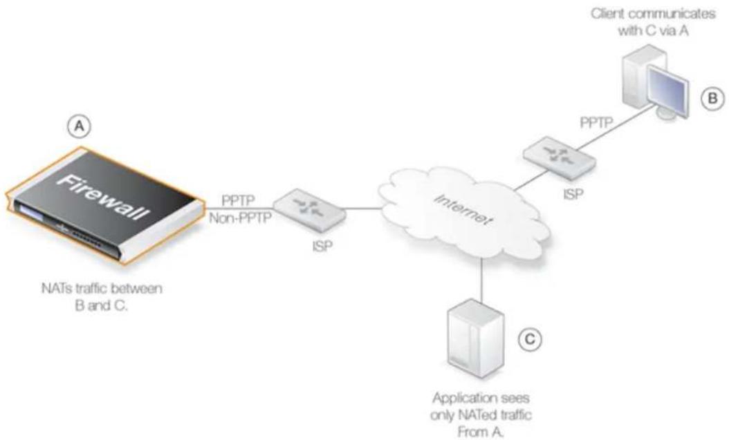
flowchart
graph TD
A["Firewall"] -->|A| B["NATs traffic between B and C."]
B -->|PPTP Non-PPTP| C["ISP"]
C --> D["Internet"]
D --> E["Application sees only NATed traffic From A."]
D --> F["PPTP"]
F --> G["Client communicates with C via A"]
F --> H["ISP"]
Figure 8.3. Anonymizing with NAT
NetDefendOS is set up with NATing IP rule set entries so it takes communication traffic coming from the client and NATs it back out onto the Internet. Communication with the client is with the PPTP protocol but the PPTP tunnel from the client terminates at the firewall. When this traffic is relayed between the firewall and the Internet, it is no longer encapsulated by PPTP.
When an application, such as a web server, now receives requests from the client it appears as though they are coming from the anonymizing service provider's external IP address and not the client's IP. The application therefore sends its responses back to the firewall which relays the traffic back to the client through the PPTP tunnel. The original IP address of the client is not revealed in traffic as it is relayed beyond the termination of the PPTP tunnel at the NetDefendOS.
Typically, all traffic passes through the same physical interface and that interface has a single public IP address. Multiple interfaces could be used if multiple public IPv4 addresses are available. There is clearly a small processing overhead involved with anonymizing traffic but this need not be an issue if sufficient hardware resources are employed to perform the anonymizing.
This same technique can also be used with L2TP instead of PPTP connections. Both protocols are discussed further in Section 10.4.4, "PPTP/L2TP Clients".
8.3. NAT Pools
Overview
Network Address Translation (NAT) provides a way to have multiple internal clients and hosts with unique private, internal IP addresses communicate to remote hosts through a single external public IPv4 address (this is discussed in depth in Section 8.2, "NAT"). When multiple public external IP addresses are available then a NAT Pool object can be used to allocate new connections across these public IPv4 addresses.
NAT Pools are usually employed when there is a requirement for huge numbers of unique port connections. The NetDefendOS Port Manager has a limit of approximately 65,000 connections for a unique combination of source and destination IP addresses. Where large number of internal clients are using applications such as file sharing software, very large numbers of ports can be required for each client. The situation can be similarly demanding if a large number of clients are accessing the Internet through a proxy-server. The port number limitation is overcome by allocating extra external IP addresses for Internet access and using NAT Pools to allocate new connections across them.
Types of NAT Pools
A NAT Pool can be one of the following three types with each allocating new connections in a different way:
- Stateful
- Stateless
- Fixed
The details of these three types are discussed next.
Stateful NAT Pools
When the Stateful option is selected, NetDefendOS allocates a new connection to the external IP address that currently has the least number of connections routed through it with the assumption that it is the least loaded. NetDefendOS keeps a record in memory of all such connections. Subsequent connections involving the same internal client/host will then use the same external IP address.
The advantage of the stateful approach is that it can balance connections across several external ISP links while ensuring that an external host will always communicate back to the same IP address which will be essential with protocols such as HTTP when cookies are involved. The disadvantage is the extra memory required by NetDefendOS to track the usage in its state table and the small processing overhead involved in processing a new connection.
To make sure that the state table does not contain dead entries for communications that are no longer active, a State Keepalive time can be specified. This time is the number of seconds of inactivity that must occur before a state in the state table is removed. After this period NetDefendOS assumes no more communication will originate from the associated internal host. Once the state is removed then subsequent communication from the host will result in a new state table entry and may be allocated to a different external IP address in the NAT Pool.
The state table itself takes up memory and it is possible to limit its size using the MaxStates property of a NAT Pool object. The state table is not allocated all at once but is incremented in size as needed. One entry in the state table tracks all the connections for a single host behind the D-Link firewall no matter which external host the connection concerns.
If the MaxStates value is reached, the state table entry with the longest idle time is replaced. If all entries in the table are active a random entry is replaced. A max_states_reached log message is generated to indicate that the maximum has been reached.
As a rule of thumb, the MaxStates value should be at least the number of local hosts or clients that will be expected to connect to using the pool.
Stateless NAT Pools
The Stateless option means that no state table is maintained and the external IP address chosen for each new connection is the one that has the least connections already allocated to it. This means two connections between one internal host to the same external host may use two different external IP addresses.
The advantage of a Stateless NAT Pool is that there is good spreading of new connections between external IP addresses with no requirement for memory allocated to a state table and there is less processing time involved in setting up each new connection. The disadvantage is that it is not suitable for communication that requires a constant external IP address.
Fixed NAT Pools
The Fixed option means that each internal client or host is allocated one of the external IP addresses through a hashing algorithm. Although the administrator has no control over which of the external connections will be used, this scheme ensures that a particular internal client or host will always communicate through the same external IP address.
The Fixed option has the advantage of not requiring memory for a state table and providing very fast processing for new connection establishment. Although explicit load balancing is not part of this option, there should be spreading of the load across the external connections due to the random nature of the allocating algorithm.
IP Pool Usage
When allocating external IP addresses to a NAT Pool it is not necessary to explicitly state these. Instead a NetDefendOS IP Pool object can be selected. IP Pools gather collections of IP addresses automatically through DHCP and can therefore supply external IP addresses automatically to a NAT Pool. See Section 5.5, "IP Pools" for more details about this topic.
Proxy ARP Usage
Where an external router sends ARP queries to the D-Link firewall to resolve external IP addresses included in a NAT Pool, NetDefendOS will need to send the correct ARP replies for this resolution to take place through its Proxy ARP mechanism so the external router can correctly build its routing table.
By default, the administrator must specify in NAT Pool setup which interfaces will be used by NAT pools. The option exists however to enable Proxy ARP for a NAT Pool on all interfaces but this can cause problems sometimes by possibly creating routes to interfaces on which packets should not arrive. It is therefore recommended that the interface(s) to be used for the NAT Pool Proxy ARP mechanism are explicitly specified.
Using NAT Pools
NAT Pools are used in conjunction with a normal NAT IP rule. When defining a NAT rule, the dialog includes the option to select a NAT Pool to use with the rule. This association brings the NAT Pool into use.
Example 8.3. Using NAT Pools
This example creates a stateful NAT pool with the external IP address range 10.6.13.10 to 10.16.13.15. This is then used with a NAT IP rule for HTTP traffic on the wan interface originating from the lan_net.
Note that if a network such as 10.6.13.0/24 is used for the NAT pool IP range, the 0 and 255 addresses (10.6.13.0 and 10.6.13.255) are automatically excluded from the range.
Command-Line Interface
A. First, create an object in the address book for the address range:
gw-world:/> add Address IP4Address nat_pool_range
Address=10.6.13.10-10.16.13.15
B. Next, create a stateful NAT Pool object called my_stateful_natpool :
gw-world:/> add NatPool my_stateful_natpool
Range=nat_pool_range
Type=Stateful
ProxyARPInterfaces=wan
C. Finally, define the NAT rule in the IP rule set:
gw-world:/> add IPRule Action=NAT
SourceInterface=lan
SourceNetwork=lannet
DestinationInterface=wan
DestinationNetwork=all-nets
Service=http-all
NATAction=UseNATPool
NATPool=my_stateful_natpool
Name=NAT_HTTP
Web Interface
A. First, create an object in the address book for the address range:
-
Go to: Objects > Address Book > Add > IP4 Address
-
Specify a suitable name for the IP range nat_pool_range
-
Enter 10.6.13.10-10.16.13.15 in the IP Address textbox
-
Click OK
B. Next, create a stateful NAT Pool object called my_stateful_natpool :
-
Go to: Objects > NAT Pools > Add > NAT Pool
-
Now enter:
-
Name: my_stateful_natpool
- Pool type: stateful
• IP Range: nat_pool_range
-
Select the Proxy ARP tab and add the WAN interface
-
Click OK
C. Finally, define the NAT rule in the IP rule set:
-
Go to: Policies > Firewalling > Main IP Rules > Add > IP Rule
-
Under General enter:
• Name: Enter a suitable name such as nat_pool_rule
• Action: NAT
-
Under Address filter enter:
-
Source Interface: Ian
• Source Network: Ian-net - Destination Interface: wan
-
Destination Network: all-nets
• Service: http-all -
Select the NAT tab and enter:
• Check the Use NAT Pool option
- Select my_stateful_natpool from the drop-down list
- Click OK
8.4. SAT
8.4.1. Introduction
NetDefendOS Static Address Translation (SAT) functionality can translate ranges of IP addresses and/or port numbers to other, predefined static values. The translation can be to a single address and/or port but can also be a transposition where each address and/or port in a range or network is mapped to a corresponding value in a new range or network.

Note: NetDefendOS SAT is the same as "port forwarding"
Some network equipment vendors use the term "port forwarding" when referring to SAT. Both terms refer to the same functionality.
Methods of Configuring SAT in NetDefendOS
There are two ways of configuring NAT in the NetDefendOS IP rule set:
- Using IP Policies
An IP Policy object can be added to the IP rule set with its Destination Address Translation property set to SAT. This is the recommended method since everything can be done with a single rule set entry and it is simpler to add other security mechanisms on the same IP rule set entry.
- Using IP Rules
An IP Rule object can be added to the IP rule set with its Action property set to SAT. A second corresponding IP rule must always also be added with its Action property set to Allow. This method can be useful for compatibility with older NetDefendOS versions but does not provide any advantages over using an IP policy.
Most of the discussion and examples in this section will assume that IP policies are being used to set up SAT. A discussion of setting up SAT using IP rules can be found towards the end in Section 8.4.9, "SAT Setup Using IP Rules".
Types of SAT Translation
SAT translation in NetDefendOS can be divided into three types:
• One-to-One - A single IP address is translated to a new single address.
- Many-to-Many - Multiple IP addresses are transposed to multiple new addresses.
- Many-to-One - Multiple IP addresses are translated to a new single address.
The values being translated may be the IP address and/or the port number for either the source or destination of new connections set up by NetDefendOS. As discussed later, the many-to-one translation is not available for port numbers.
Specifying the Type of IP Address Mapping
NetDefendOS recognizes the type of SAT IP address mapping using the following rules:
- One-to-One
If the original address is a single IP address then a one-to-one mapping is always performed. The new IP address should also be a single address. This is the most common usage of SAT and is described further in Section 8.4.2, "One-to-One IP Translation".
- Many-to-Many
If the original address is an IP range or network then a many-to-many mapping is always performed provided that transposition is selected.
With a many-to-many mapping, a single new IP address is specified and the mappings are performed incrementally starting from that address. If an entire network is being transposed to another network then the new IP address should be the first address in the new network. For example, 192.168.1.0.
This translation type is described further in Section 8.4.3, "Many-to-Many IP Translation".
- Many-to-One
When an many-to-one mapping is performed, the original source address should be a range or network and the new destination address should be a single IP address. Transposition should not be enabled.
When the source address is all-nets, an many-to-one SAT mapping is always used.
This translation type is described further in Section 8.4.4, "Many-to-One IP Translation".
Configuring SAT Using an IP Policy
When creating a SAT IP policy, translation can be specified for source or destination translation, or both. The way the translation functions for the source and/or destination address is determined by specifying one or both of the following actions:
- Address Action
This determines how the IP address is translated and can be one of the following:
i. Single IP - Either a single original IP or a range/network will be translated to the single new IP address specified. This yields both a one-to-one or a many-to-one IP address translation.
ii. Transposed - This yields a many-to-many translation where each address in the original range/network is transposed to a new range/network, using the specified new IP address as the base address for the transposition.
- Port Action
This determines how the IP address is translated and can be one of the following:
i. None - No port translation takes place.
ii. Single Port - This is used for a one-to-one translation to the new port number specified.
iii. Transposed - This transposes a range of port numbers to a new range using the new port number as a base for the transposition. This is for a many-to-many port translation.
Port translation is described further in Section 8.4.7, "Port Translation".
The sections that follow show how the different kinds of SAT translation can be configured.
Using the Auto Setting for Source Translation
An IP Policy has a default value of Auto for its Source Translation property. In the examples in this section, the Source Translation will be set to None or Transpose so it is clear what action is being performed.
The behavior of the Auto setting for source translation is discussed in Section 8.5, "Automatic Translation".
8.4.2. One-to-One IP Translation
The simplest form of SAT usage is the translation of a single IP address to another single, static address. A very common scenario for this usage is to enable external users to access a protected server in a DMZ that has a private address. This is also sometimes referred to as implementing a Virtual IP or a Virtual Server and is often used in conjunction with a DMZ.
The Role of a DMZ
At this point, it is relevant to discuss the role of the network known as the Demilitarized Zone (DMZ) since SAT rules are often used for allowing DMZ access.
The DMZ's purpose is to have a network where the administrator can place those resources which will be accessed by external, untrusted clients and where this access typically takes place across the public Internet. The servers in the DMZ will have the maximum exposure to external threats and are therefore at most risk of being compromised.
By isolating these servers in a DMZ, the object is to create a distinct network, separated from much more sensitive local, internal networks. This allows NetDefendOS to have control over what traffic flows between the DMZ and internal networks and to better isolate any security breaches that might occur in DMZ servers.

Note: The DMZ port could be any port
On some models of D-Link NetDefend hardware, there is a specific Ethernet interface which is marked as being for the DMZ network. Although this is the port's intended use, it could be used for other purposes and any Ethernet interface could also be used instead for a DMZ.
Example 8.4. One-to-One IP Translation Using an IP Policy
In this example, SAT will be set up to translate and allow HTTP and HTTPS connections from the Internet to a web server located in a DMZ. The scenario is illustrated in the diagram below.
The firewall is connected to the Internet via the wan interface with address object wan_ip as its
public IPv4 address. The web server has the private IPv4 address 10.0.0.5 and is reachable through the dmz interface. The port number will not be translated.
Command-Line Interface
Create a SAT IP Policy:
gw-world:/> add IPPolicy Name=sat_http_to_dmz
SourceInterface=wan
SourceNetwork=all-nets
DestinationInterface=core
DestinationNetwork=wan_ip
Service=http-all
Action=Allow
SourceAddressTranslation=None
DestinationAddressTranslation=SAT
DestinationAddressAction=SingleIP
DestNewIP=10.0.0.5
Web Interface
Create a SAT IP policy:
-
Go to: Policies > Firewalling > Main IP Rules > Add > IP Policy
-
Now enter:
-
Name: sat_http_to_dmz
-
Action: Allow
-
Under Filter enter:
-
Source Interface: wan
- Source Network: all-nets
- Destination Interface: core
-
Destination Network: wan_ip
• Service: http-all -
Under Source Translation enter:
- Address Translation: None
-
Under Destination Translation enter:
-
Address Translation: SAT
• Address Action: Single IP -
New IP Address: 10.0.0.5
-
Click OK
The preceding example results in the following being added to the main IP rule set:
| # | Action | Src Iface | Src Net | Dest Iface | Dest Net | Service | SAT Action |
| 1 | Allow/SAT wan all-nets | core wan_ip | http-all Destination IP: 10.0.0.5 | ||||
The SAT rule destination interface must be core (in other words, NetDefendOS itself) because interface IPs are always routed on core.
Now consider, the scenario illustrated below, where there are internal clients on the lan_net network which also which to access the web server in the DMZ.
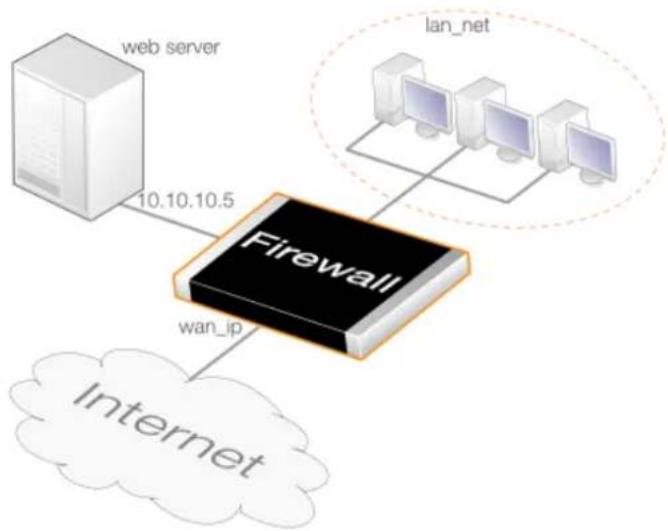
flowchart
graph TD
A["web server"] -->|10.10.10.5| B["Firewall"]
C["lan_net"] --> B
B --> D["Internet"]
B --> E["wan_ip"]
Figure 8.4. SAT Translation with Internal Clients
If the internal clients require access to the Internet, a NAT IP rule set entry is also needed. However, this will not provide access to the web server because the source interface of the SAT IP policy does not include the Ian interface. This problem can be solved in one of the following two ways:
• Change the Source Interface Value
Give the Source Interface of the SAT IP policy the value all. The resulting IP rule set would then contain the following entries:
| # | Action | Src Iface | Src Net | Dest Iface | Dest Net | Service | SAT Action |
| 1 | Allow/SAT | any | all-nets | core | wan_ip | http-all | Destination IP: 10.0.0.5 |
| 2 | Allow/NAT | lan | lan_net | any | all-nets | http-all |
• Use an Interface Group
Create an Interface Group object which consists of the wan and Ian interfaces and assign it to the Source Interface property. This is a more restrictive solution and is therefore better from a security perspective.
• Use the IP Policy Automatic Translation Feature
Using the automatic translation feature of an IP policy is the simplest solution and is described in Section 8.5, "Automatic Translation". A single IP policy can be created which both performs the SAT translation and the NAT translation required by internal clients, as illustrated in Example 8.14, "Automatic SAT/NAT Translation with an IP Policy".
However, if the web server is on the same network as the client, a different approach is required and this is described in Section 8.4.6, "Combining SAT with NAT".
8.4.3. Many-to-Many IP Translation
A single SAT IP rule set entry can be used to transpose an entire range or network of IP addresses to another range or network. The result is a many-to-many translation where the first original IP address is translated to the first IP address in the new range or network, then the second to the second, and so on.
To tell NetDefendOS to perform this type of translation, the original IP address must be a range or network and the IP policy's Address Action property must be set to the value Transposed. The new range or network is specified using a single IP address which is the starting address for the transposition. For example, 192.168.1.0 would be specified as the new address if the transposition is to the network 192.168.1.0/24 and starting from the first address in the network.
As another example, a SAT IP rule set entry might specify that connections to the 194.1.2.16/29 network should be translated to 192.168.0.50. The IP policy for this would be:
| # | Action | Src Iface | Src Net | Dest Iface | Dest Net | Service | SAT Action |
| 1 | Allow/SAT | any | all-nets | core | 194.1.2.16/29 | all_services | Destination IP: 192.168.0.50 |
This IP policy would result in the following translations:
| Original Destination Address | Translated Destination Address |
| 194.1.2.16 | 192.168.0.50 |
| 194.1.2.17 | 192.168.0.51 |
| 194.1.2.18 | 192.168.0.52 |
| 194.1.2.19 | 192.168.0.53 |
| 194.1.2.20 | 192.168.0.54 |
| 194.1.2.21 | 192.168.0.55 |
| 194.1.2.22 | 192.168.0.56 |
| 194.1.2.23 | 192.168.0.57 |
These translations will mean:
- Attempts to communicate with 194.1.2.16 will result in a connection to 192.168.0.50.
- Attempts to communicate with 194.1.2.22 will result in a connection to 192.168.0.56.
An example of an application for this feature is when there are several protected servers in a DMZ, and each server is to be accessible using a unique public IPv4 address.
Setting Up Many-to-Many SAT Translation
The following steps are needed for setting up many-to-many SAT translation:
- Define an address object containing the range of public IPv4 addresses.
- Define another address object for the base address of the web server IP addresses.
• ARP publish the public IPv4 addresses on the interface connected to the Internet.
• Create an IP Policy object that will perform the SAT translation.
Example 8.5. Many-to-Many SAT Translation Using an IP Policy
In this example, an IP policy will translate from five public IPv4 addresses to five web servers located in a DMZ. The firewall is connected to the Internet via the wan interface and the public IPv4 addresses have the range 203.0.113.1-205.0.113.5. The web servers have the private IPv4 address range 10.0.0.5-10.0.0.9 and are on the network connected to the dmz interface.
Note that since the public IPv4 addresses will be manually ARP published, these addresses are not routed on core so the SAT destination interface is wan and not core.
Command-Line Interface
Create an address object for the public IPv4 addresses:
gw-world:/> add Address IP4Address wwwsrv_pub
Address=203.0.113.1-205.0.113.5
Now, create another object for the base of the web server IP addresses:
gw-world:/> add Address IP4Address wwwsrv_priv_base Address=10.0.0.5
Publish the public IPv4 addresses on the wan interface using ARP publish. One ARP object is needed for every public IP address:
gw-world:/> add ARP Interface=wan IP=203.0.113.1 Mode=Publish
Repeat this for all the remaining public IPv4 addresses.
Create an IP policy for the translation:
gw-world:/> add IPPolicy Name=sat_http_to_dmz
SourceInterface=any
SourceNetwork=all-nets
DestinationInterface=wan
DestinationNetwork=wwwsrv_pub
Service=http-all
Action=Allow
SourceAddressTranslation=None
DestinationAddressTranslation=SAT
DestinationAddressAction=Transposed
DestBaseIP=wwwsrv_priv_base
Web Interface
Create an address object for the public IPv4 address range:
-
Go to: Objects > Address Book > Add > IP4 Address
-
Now enter:
-
Name: wwwsrv_pub
• IP Address: 203.0.113.1-205.0.113.5 -
Click OK
Now, create another address object for the base of the web server IP addresses:
- Go to: Objects > Address Book > Add > IP4 Address
2. Now enter:
- Name: wwwsrv_priv_base
• IP Address: 10.0.0.5
3. Click OK
Publish the public addresses on the wan interface using ARP publish. One ARP item is needed for every IP address:
-
Go to: Network > Interfaces and VPN > ARP/Neighbor Discovery > Add > ARP/Neighbor Discovery
-
Now enter:
-
Mode: Publish
-
Interface: wan
• IP Address: 203.0.113.1 -
Click OK and repeat the other public IPv4 addresses
Create a SAT rule for the translation:
-
Go to: Policies > Firewalling > Main IP Rules > Add > IP Policy
-
Now enter:
-
Name: sat_http_to_dmz
• Action: SAT -
Under Filter enter:
-
Source Interface:any
• Source Network: all-nets - Destination Interface: wan
-
Destination Network: wwwsrv_pub
• Service: http-all -
Under Source Translation enter:
- Address Translation: None
-
Under Destination Translation enter:
-
Address Translation: SAT
-
Address Action: Transposed
• Base IP Address: wwwsrv_priv -
Click OK
8.4.4. Many-to-One IP Translation
NetDefendOS can be used to translate a range or a network to a single IP address. Suppose that the requirement is to translate a range of destination IPv4 addresses which includes 194.1.2.16 to 194.1.2.20 plus 194.1.2.30 to the single IPv4 address 102.168.0.50. The port number will remain unchanged.
The IP rule set entry to perform the translation would be:
| # | Action | Src Iface | Src Net | Dest Iface | Dest Net | Service | SAT Action |
| 1 | Allow/SAT any all-nets wan | 194.1.2.16- | 194.1.2.20, 194.1.2.30 | http-all | Destination IP: 192.168.0.50 | ||
The following are some examples of how this rule rule set entry would perform translations:
- Attempts to communicate with IPv4 address 194.1.2.16, will result in a connection to 192.168.0.50.
- Attempts to communicate with IPv4 address 194.1.2.30, will result in a connection to 192.168.0.50.
Example 8.6. Many-to-One SAT Translation Using an IP Policy
In this example, the firewall is connected to the Internet via the wan interface and the public IPv4 addresses have the range of 203.0.113.6-203.0.113.9. The server has the private IPv4 address 10.0.0.5 and is on the network connected to the dmz interface.
The steps used to set this up will be the following:
- Define an address object containing all the public IPv4 addresses.
- Define another address object set to be the private IPv4 address of the web server.
- ARP publish the public IPv4 addresses on the interface connected to the Internet.
- Create an IP policy that will perform the SAT translation.
Note that since the public IPv4 addresses will be manually ARP published, these addresses are not routed on core so the SAT destination interface is wan and not core.
Command-Line Interface
Create an address object for the public IPv4 addresses:
gw-world:/> add Address IPAddress wwwsrv_pub
Address=203.0.113.6-203.0.113.9
Now, create another object for the web server's private IP addresses:
gw-world:/> add Address IPAddress wwwsrv_priv Address=10.0.0.5
Publish the public IPv4 addresses on the wan interface using ARP publish. A command like the following is needed for each public IP address:
gw-world:/> add ARP Interface=wan IP=203.0.113.6 mode=Publish
Repeat this command for the other public IP addresses.
Create a SAT IP rule for the translation:
gw-world:/> add IPPolicy Name=sat_all_to_one
SourceInterface=any
SourceNetwork=all-nets
DestinationInterface=wan
DestinationNetwork=wwwsrv_pub
Service=http-all
Action=Allow
SourceAddressTranslation=None
DestinationAddressTranslation=SAT
DestinationAddressAction=SingleIP
DestNewIP=wwwsrv_priv
Web Interface
Create an address object for the public IPv4 address range:
-
Go to: Objects > Address Book > Add > IP4 Address
-
Now enter:
-
Name: wwwsrv_pub
• IP Address: 203.0.113.6-205.0.113.9 -
Click OK
Now, create another address object for the web server's private IP address:
-
Go to: Objects > Address Book > Add > IP4 Address
-
Now enter:
-
Name: wwwsrv_priv
-
IP Address: 10.0.0.5
-
Click OK
Publish the public addresses on the wan interface using ARP publish. One ARP item is needed for every IP address:
-
Go to: Network > Interfaces and VPN > ARP/Neighbor Discovery > Add > ARP/Neighbor Discovery
-
Now enter:
-
Mode: Publish
-
Interface: wan
• IP Address: 203.0.113.6 -
Click OK and repeat the other public IPv4 addresses
Create a SAT IP rule for the translation:
-
Go to: Policies > Firewalling > Main IP Rules > Add > IP Policy
-
Now enter:
-
Name: sat_all_to_one
-
Action: Allow
-
Under Filter enter:
-
Source Interface: any
- Source Network: all-nets
- Destination Interface: wan
-
Destination Network: wwwsrv_pub
• Service: http-all -
Under Source Translation enter:
- Address Translation: None
-
Under Destination Translation enter:
-
Address Translation: SAT
• Address Action: Single IP
• New IP Address: wwwsrv_priv -
Click OK
8.4.5. SAT with Stateless IP Rule Set Entries
It is possible to configure SAT with IP rule set entries that are "stateless". In other words, entries which do not track the packets flowing between source and destination as part of a single connection. This means that two rule set entries will be needed, one for each direction of traffic flow. Returning traffic must be also explicitly translated by the second entry.
Instead of using IP Policy objects to set this up, a Stateless Policy should be used instead.
The following table shows the correct configuration of SAT Stateless Policy objects added to the IP rule set for connections to a web server with the private IP address wwwwsrv located on an dmz interface.
| # | Action | Src Iface | Src Net | Dest Iface | Dest Net | Service | SAT Action |
| 1 | Allow/SAT | any | all-nets | core | wan_ip | http-all | Destination IP: wwwsrv |
| 2 | Allow/SAT | dmz | wwwsrv | any | all-nets | http-all | Source IP: wan_ip |
Notice that in the second entry, the source IP is being translated instead of the destination IP since this is the returning traffic.
Example 8.7. Stateless One-to-One SAT Translation Using Stateless Policies
This example repeats Example 8.4, "One-to-One IP Translation Using an IP Policy" but uses stateless policies instead of IP policies. Two policies are needed, one for each direction of traffic flow.
Command-Line Interface
Create a SAT Stateless Policy for inbound traffic:
gw-world:/> add IPPolicy Name=stateless_sat_inbound_to_dmz
SourceInterface=wan
SourceNetwork=all-nets
DestinationInterface=core
DestinationNetwork=wan_ip
Service=http-all
Action=Allow
SourceAddressTranslation=None
DestinationAddressTranslation=SAT
DestinationAddressAction=SingleIP
DestNewIP=10.0.0.5
Create a SAT Stateless Policy for outbound traffic:
gw-world:/> add IPPolicy Name=stateless_sat_outbound_from_dmz
SourceInterface=dmz
SourceNetwork=10.0.0.5
DestinationInterface=any
DestinationNetwork=all-nets
Service=http-all
Action=Allow
SourceAddressTranslation=SAT
SourceAddressAction=SingleIP
SourceNewIP=wan_ip
Web Interface
Create a SAT Stateless Policy for inbound traffic:
-
Go to: Policies > Firewalling > Main IP Rules > Add > Stateless Policy
-
Now enter:
-
Name: stateless_sat_inbound_to_dmz
-
Action: Allow
-
Under Filter enter:
-
Source Interface: wan
- Source Network: all-nets
- Destination Interface: core
-
Destination Network: wan_ip
• Service: http-all -
Under Source Translation enter:
- Address Translation: None
-
Under Destination Translation enter:
-
Address Translation: SAT
• Address Action: Single IP - New IP Address: 10.0.0.5
6. Click OK
Create a SAT Stateless Policy for outbound traffic:
-
Go to: Policies > Firewalling > Main IP Rules > Add > Stateless Policy
-
Now enter:
-
Name: stateless_sat_http_outbound_from_dmz
-
Action: Allow
-
Under Filter enter:
-
Source Interface: dmz
• Source Network: 10.0.0.5 - Destination Interface: wan
-
Destination Network: all-nets
• Service: http-all -
Under Source Translation enter:
- Address Translation: None
-
Under Source Translation enter:
-
Address Translation: SAT
• Address Action: Single IP -
New IP Address: wan_ip
-
Click OK
8.4.6. Combining SAT with NAT
Sometimes SAT must be combined with NAT in a single IP policy where not only the destination IP address must be changed with SAT but also the source IP address must be changed with NAT so the destination of the traffic can send its reply back to the sender.
This issue was mentioned at the end of Section 8.4.2, "One-to-One IP Translation" where clients sending HTTP/HTTP requests to a web server are on the same internal network as the server. It is never recommended to have clients and server on the same network but it could arise.
The following IPv4 addresses will be assumed to explain the problem:
- wan_ip (203.0.113.10): the firewall's public IPv4 address
• lan_ip (10.0.0.1): the local network's private IPv4 address
- wwwsrv_ip (10.0.0.2): the web server's private IPv4 address
- client_ip (10.0.0.3): the local client's private IPv4 address
The diagram below illustrates the topology of the network which uses these IP addresses.
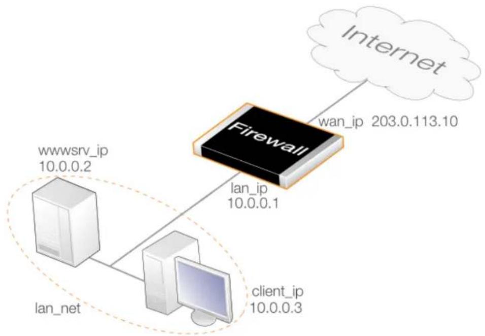
flowchart
graph TD
Firewall["Firewall"] -->|wan_ip 203.0.113.10| Internet["Internet"]
Firewall -->|lan_ip 10.0.0.1| client_ip["client_ip 10.0.0.3"]
Firewall -->|wwwsrv_ip 10.0.0.2| client_ip
Firewall -->|lan_net| client_ip
Figure 8.5. Combining SAT with NAT in an IP Policy
Also assume that the following single IP policy exists to SAT traffic arriving at public wan_ip address to the private wwwsrv_ip address of the web server.
| # | Action | Src Iface | Src Net | Dest Iface | Dest Net | Service | SAT Action |
| 1 | Allow/SAT | any | all-nets | core | wan_ip | http-all | Destination IP: wwwsrv_ip |
This IP policy will not work for traffic coming from clients on the same network as the web server. The reason is that when such a client receives the reply, the source address will not match the IP address to which the request was sent. This results in the client ignoring the reply. The following sequence of events explains why this occurs:
- The local client performs a public DNS lookup for the web server IP and then sends an HTTP request to wan_ip to reach the web server.
$$ 1 0. 0. 0. 3: 1 0 3 8 \Rightarrow 2 0 3. 0. 1 1 3. 1 0: 8 0 $$
- The SAT IP policy 1 allows the traffic and translates the destination address to wwwsrv_ip:
$$ 1 0. 0. 0. 3: 1 0 3 8 = > 1 0. 0. 0. 2: 8 0 $$
- The server at wwwsrv_ip processes the request and replies to the original client address:
$$ 1 0. 0. 0. 2: 8 0 = > 1 0. 0. 0. 3: 1 0 3 8 $$
However, the reply will travel to the client across the local network, bypassing the firewall.
- The client expects a reply from 203.0.113.10:80 and not 10.0.0.2:80 so the response is discarded by the client and it will continue to wait for a response from 203.0.113.10:80, which will never arrive.
One possible solution to the problem is for the client to communicate directly to the web server since they are on the same network. However, this would require an internal DNS server so that the client could discover the private address of the web server.
A better solution is to add a second IP policy which applies NAT to the client traffic so the source becomes wan_ip and also applies SAT so the destination becomes wwwsrv_ip. This new IP policy is shown in the table below:
| # | Action | Src Iface | Src Net | Dest Iface | Dest Net | Service | SAT Action |
| 1 | Allow/SAT | any | all-nets | core | wan_ip | http-all | Destination IP: wwwsrv_ip |
| 2 | Allow NAT/SAT | lan | lan_net | core | wan_ip | http-all | Destination IP: wwwsrv_ip (SAT)Source IP: wan_ip (NAT) |
The sequence of events would now become the following:
- The client sends traffic to wan_ip in order to reach the webserver:
10.0.0.3:1038 => 203.0.113.10:80
- NetDefendOS translates the connection in accordance with rule 2
10.0.0.1:32789 => 10.0.0.2:80
- The server at wwwsrv_ip processes the traffic and replies:
10.0.0.2:80 => 10.0.0.1:32789
- The reply is processed by NetDefendOS so that the translation rules are applied in the reverse order and it arrives at the client with the expected source address:
203.0.113.10:80 => 10.0.0.3:1038
The client now has the reply it was expecting from the correct source IP address.
The example below shows exactly how this new NAT/SAT IP policy would be created.
Example 8.8. Combining SAT with NAT in an IP Policy
This example shows how the combined SAT/NAT IP policy is created to solve the problem of HTTP clients needing to access a web server which is located on the same network. The network setup shown in Figure 8.5, "Combining SAT with NAT in an IP Policy" will be assumed, where both clients and the server are on the lan_net network.
Command-Line Interface
Create a SAT IP Policy:
gw-world:/> add IPPolicy Name=sat_nat_http
SourceInterface=lan
SourceNetwork=lan_net
DestinationInterface=core
DestinationNetwork=wan_ip
Service=http-all
Action=Allow
SourceAddressTranslation=NAT
NATSourceAddressAction=OutgoingInterfaceIP
DestinationAddressTranslation=SAT
DestinationAddressAction=SingleIP
DestNewIP=wwwsrv_ip
Web Interface
Create a SAT IP policy:
-
Go to: Policies > Firewalling > Main IP Rules > Add > IP Policy
-
Now enter:
-
Name: sat_nat_http
-
Action: Allow
-
Under Filter enter:
-
Source Interface: Ian
- Source Network: lan_net
- Destination Interface: core
-
Destination Network: wan_ip
• Service: http-all -
Under Source Translation enter:
-
Address Translation: NAT
• Address Action: Outgoing Interface IP -
Under Destination Translation enter:
-
Address Translation: SAT
• Address Action: Single IP
• New IP Address: wwwsrv_ip -
Click OK
Configuring NAT/SAT Using the Automatic Translation Option
It is also possible to configure NAT and SAT together in a single IP Policy to solve the internal clients problem. This is done by using the Auto option for the IP policy's source translation. This is explained further in Section 8.5, "Automatic Translation" and can be used to allow protected clients access to a protected webserver, whether they are on the same network as the server or not.
8.4.7. Port Translation
Port Address Translation (PAT) can be used to modify the source or destination port of a connection. In previous SAT examples, a new port number was not been specified and the
original port number was used by default. If the port number is specified, both the IP address and the port number can be translated.
Only one-to-one and many-to-many port translation can be performed with port translation. It is not possible to perform many-to-one port translation.
Enabling Port Mapping
To enable port mapping, the Port Action property of the SAT IP policy must be specified as either Single Port or Transposed. Both of these values require a port number to be specified for either the new single port number for one-to-one translation or a base port number for many-to-many translation.
Port Mapping Rules for the Service Used
The following rules should be noted for how port mapping functions with the Service object assigned to an IP policy that will perform SAT translation:
- If the Service object used with the IP rule set entry does not have a single value or simple range specified for its port property, port translation will never be performed.
The term simple range means a range with only a lower and upper value or a single value. For example, 50-60 is a simple range.
- If the Port Action is specified as Single Port with a value for New Port, and the Service object used has a single number for its port property, then all connections will be translated to the new port number.
- If the Port Action is specified as Transposed with a Base Port value, and the Service object has a simple number range for its port property, then all connections will be transposed to a new range which begins with the base port number.
An Example of Port Translation
Consider the following SAT IP policy that has a Service object associated with it which has the simple port range 80-85. The entry specifies that the destination address wwwsrv_pub will be translated to wwwsrv_priv. In addition, the port action is set to Transposed with the Base Port set to 1080 so only the ports will be subject to a many-to-many translation.
| # | Action | Src Iface | Src Net | Dest Iface | Dest Net | Service | SAT Action |
| 1 | Allow/SAT | any | all-nets | wan | wwwsrv_pub | TCP 80-85 | Destination IP: wwwsrv_privAction: TransposedBase Port:1080 |
This rule set entry produces a many-to-many translation of all ports in the range 80-85 to the range 1080-1085. For example, the following would happen:
- Attempts to communicate with the web server's public address - port 80, will result in a connection to the web server's private address - port 1080.
- Attempts to communicate with the web server's public address - port 84, will result in a connection to the web server's private address - port 1084.
If the Service was changed so that only the single port value 80 was specified for its Port property then the IP rule set entry would only trigger for port 80 and it would always be translated to the new port 1080 (a one-to-one relationship)
Example 8.9. Port Translation Using an IP Policy
This example repeats Example 8.4, "One-to-One IP Translation Using an IP Policy" but uses a custom service that allows protocols connecting on ports 80 to 85. It also performs a many-to-many port mapping so the destination port range 80-85 becomes the range 1080-1085.
Note that a protocol would also need to be assigned to the service object created if any ALGs were going to be used with the IP policy.
Command-Line Interface
Create a custom service:
gw-world:/> add Service ServiceTCPUDP my_sat_service
Type=TCP
DestinationPorts=80-85
Create a SAT IP policy:
gw-world:/> add IPPolicy Name=sat_port_translate
SourceInterface=wan
SourceNetwork=all-nets
DestinationInterface=core
DestinationNetwork=wan_ip
Service=my_sat_service
Action=Allow
SourceAddressTranslation=None
DestinationAddressTranslation=SAT
DestinationAddressAction=SingleIP
DestNewIP=10.0.0.5
DestPortAction=Transpose
DestBasePort=1080
Web Interface
Create a custom service:
-
Go to: Local Objects > Services > Add > TCP/UDP service
-
Now enter:
-
Name: my_sat_service
- Type: TCP
-
Destination port: 80-85
-
Click OK
Create a SAT IP policy:
- Go to: Policies > Firewalling > Main IP Rules > Add > IP Policy
- Now enter:
- Name: sat_port_translate
- Action: Allow
3. Under Filter enter:
- Source Interface: wan
- Source Network: all-nets
- Destination Interface: core
- Destination Network: wan_ip
• Service: my_sat_service
4. Under Source Translation enter:
- Address Translation: None
5. Under Destination Translation enter:
- Address Translation: SAT
• Address Action: Single IP - New IP Address: 10.0.0.5
- Port Action: Transposed
- Base Port: 1080
6. Click OK
8.4.8. Protocols Handled by SAT
Generally, SAT can handle all protocols that allow address translation to take place. However, there are protocols that can only be translated in special cases, and other protocols that cannot be translated at all.
Protocols that are impossible to translate using SAT are most likely also impossible to translate using NAT. The reasons for this include the following:
- The protocol cryptographically requires that the addresses are unaltered. This applies to many VPN protocols.
- The protocol embeds its IP addresses inside the TCP or UDP data level and requires that the addresses visible on the IP level are the same as those embedded in the data. Examples of this include FTP.
- Either party is attempting to open new dynamic connections to the addresses visible to that party. In some cases, this can be resolved by modifying the application or the NetDefendOS configuration.
There is no definitive list of what protocols can or cannot be address translated. A general rule is that VPN protocols cannot usually be translated. In addition, protocols that open secondary connections in addition to the initial connection can be difficult to translate.
Some protocols that are difficult to address translate may be handled by specially written algorithms designed to read and/or alter application data. These are commonly referred to as Application Layer Gateways or Application Layer Filters. NetDefendOS supports a number of such Application Layer Gateways and for more information please see Section 6.1, "ALGs".
8.4.9. SAT Setup Using IP Rules
SAT Requires Multiple IP Rules
SAT transaltion with IP rules requires more than a single IP rule when it is configured. A SAT rule that triggers for the target traffic must first be created to specify the translation required. However, NetDefendOS does not terminate rule set lookups after finding a matching SAT rule. Instead, the IP rule set search continues for a matching Allow, NAT or FwdFast IP rule. Only when NetDefendOS finds such a second matching rule is the SAT IP rule applied to the traffic. Contrast this with using IP policies where only a single IP Policy object is needed.
The SAT rule only defines the translation that is to take place. The second, associated IP rule, will actually allow the traffic to flow.
The Second Rule Triggers on the Untranslated IP Address
An important principle to keep in mind when creating IP rules for SAT is that the second rule, for example an Allow rule, must trigger on the old, untranslated IP address (either source or destination IP depending on the type of SAT rule). A common mistake is to create a second IP rule expecting that it should trigger on the new, translated IP address.
For example, if a SAT rule translates the destination IPv4 address from 192.168.0.1 to 172.16.0.1 then the second associated rule should allow traffic to pass to the destination 192.168.0.1 and not 172.16.0.1.
Only after the second rule triggers to allow the traffic, is the route lookup then done by NetDefendOS on the translated destination address to work out which interface the traffic should be sent from.
SAT IP Rule Properties
A SAT IP rule is similar to other types of IP rules in that it triggers on a combination of source network/interface plus destination network/interface plus service. A SAT IP rule has the following additional properties:
- SAT Translate
This specifies the address that will be changed and can be one of:
i. Destination IP - The original destination IP will be translated.
ii. Source IP - The original source IP will be translated.
- New IP Address
The new address for the translation.
- New Port
The new port number used for translation. As explained below, port translation happens independently of address translation and follows slightly different rules.
- All-to-One Mapping
This is enabled if the mapping is to be many IP addresses to a single IP address. It is not used for port translation as all-to-one port translation is not possible.
Example 8.10. One-to-One IP Translation Using IP Rules
This example repeats Example 8.4, "One-to-One IP Translation Using an IP Policy" but uses IP rules instead of IP policies.
Command-Line Interface
Create a SAT IP rule:
gw-world:/> add IPRule Action=SAT
SourceInterface=wan
SourceNetwork=all-nets
DestinationInterface=core
DestinationNetwork=wan_ip
Service=http-all
SATTranslate=DestinationIP
SATTranslateToIP=10.0.0.5
Name=SAT_HTTP_To_DMZ
Then create a corresponding Allow rule:
gw-world:/> add IPRule Action=Allow
SourceInterface=wan
SourceNetwork=all-nets
DestinationInterface=core
DestinationNetwork=wan_ip
Service=http-all
Name=Allow_HTTP_To_DMZ
Web Interface
First create a SAT rule:
-
Go to: Policies > Firewalling > Main IP Rules > Add > IP Rule
-
Specify a suitable name for the rule, for example SAT_HTTP_To_DMZ
-
Now enter:
• Action: SAT
• Service: http-all
- Source Interface: wan
- Source Network: all-nets
- Destination Interface: core
- Destination Network: wan_ip
• SAT Translate: Destination IP
- New IP Address: 10.0.0.5
- Click OK
Then create a corresponding Allow rule:
- Go to: Policies > Firewalling > Main IP Rules > Add > IP Rule
- Specify a suitable name for the rule, for example Allow_HTTP_To_DMZ
- Now enter:
- Action: Allow
• Service: http-all - Source Interface: wan
- Source Network: all-nets
- Destination Interface: core
-
Destination Network: wan_ip
-
Click OK
Example 8.11. Many-to-Many SAT Translation Using IP Rules
This example repeats Example 8.5, "Many-to-Many SAT Translation Using an IP Policy" but uses IP rules instead of IP policies.
Command-Line Interface
Create an address object for the public IPv4 addresses:
gw-world:/> add Address IP4Address wwwsrv_pub
Address=203.0.113.1-205.0.113.5
Now, create another object for the base of the web server IP addresses:
gw-world:/> add Address IP4Address wwwsrv_priv_base Address=10.0.0.5
Publish the public IPv4 addresses on the wan interface using ARP publish. One ARP object is needed for every public IP address:
gw-world:/> add ARP Interface=wan IP=203.0.113.1 mode=Publish
Repeat this for all the remaining public IPv4 addresses.
Create a SAT rule for the translation:
gw-world:/> add IPRule Action=SAT
SourceInterface=any
SourceNetwork=all-nets
DestinationInterface=wan
DestinationNetwork=wwwsrv_pub
Service=http-all
SATTranslateToIP=wwwsrv_priv_base
SATTranslate=DestinationIP
Finally, create an associated Allow Rule:
gw-world:/main> add IPRule Action=Allow
SourceInterface=any
SourceNetwork=all-nets
DestinationInterface=wan
DestinationNetwork=wwwsrv_pub
Service=http-all
Web Interface
Create an address object for the public IPv4 address range:
-
Go to: Objects > Address Book > Add > IP4 Address
-
Now enter:
-
Name: wwwsrv_pub
• IP Address: 203.0.113.1-205.0.113.5 -
Click OK
Now, create another address object for the base of the web server IP addresses:
- Go to: Objects > Address Book > Add > IP4 Address
-
Now enter:
-
Name: wwwsrv_priv_base
• IP Address: 10.0.0.5 -
Click OK
Publish the public addresses on the wan interface using ARP publish. One ARP item is needed for every IP address:
- Go to: Network > Interfaces and VPN > ARP/Neighbor Discovery > Add > ARP/Neighbor Discovery
-
Now enter:
-
Mode: Publish
-
Interface: wan
• IP Address: 203.0.113.1 -
Click OK and repeat the other public IPv4 addresses
Create a SAT rule for the translation:
- Go to: Policies > Firewalling > Main IP Rules > Add > IP Rule
- Specify a suitable name for the rule, for example SAT_HTTP_To_DMZ
- Now enter:
• Action: SAT
• Service: http-all
- Source Interface:any
- Source Network: all-nets
- Destination Interface: wan
- Destination Network: wwwsrv_pub
• SAT Translate: Destination IP
• New IP Address: wwwsrv_priv
4. Click OK
Finally, create a corresponding Allow rule:
- Go to: Policies > Firewalling > Main IP Rules > Add > IP Rule
- Specify a suitable name for the rule, for example Allow_HTTP_To_DMZ
- Now enter:
- Action: Allow
• Service: http-all - Source Interface:any
• Source Network: all-nets - Destination Interface: wan
- Destination Network: wwwsrv_pub
4. Click OK
Example 8.12. All-to-One SAT Translation Using IP Rules
This example repeats Example 8.6, "Many-to-One SAT Translation Using an IP Policy" but uses IP rules instead of IP policies.
Command-Line Interface
Create an address object for the public IPv4 addresses:
gw-world:/> add Address IPAddress wwwsrv_pub
Address=203.0.113.6-203.0.113.9
Now, create another object for the web server's private IP addresses:
gw-world:/> add Address IPAddress wwwsrv_priv Address=10.0.0.5
Publish the public IPv4 addresses on the wan interface using ARP publish. A CLI command like the following is needed for each public IP address:
gw-world:/> add ARP Interface=wan IP=203.0.113.6 mode=Publish
Repeat this command for the other public IP addresses.
Create a SAT IP rule for the translation:
gw-world:/> add IPRule Action=SAT
SourceInterface=any
SourceNetwork=all-nets
DestinationInterface=wan
DestinationNetwork=wwwsrv_pub
Service=http-all
SATTranslateToIP=wwwsrv_priv
SATTranslate=DestinationIP
SATAllToOne=Yes
Finally, create an associated Allow rule:
gw-world:/> add IPRule Action=Allow
SourceInterface=any
SourceNetwork=all-nets
DestinationInterface=wan
DestinationNetwork=wwwsrv_pub
Service=http-all
Web Interface
Create an address object for the public IPv4 address range:
-
Go to: Objects > Address Book > Add > IP4 Address
-
Now enter:
-
Name: wwwsrv_pub
• IP Address: 203.0.113.6-205.0.113.9 -
Click OK
Now, create another address object for the web server's private IP address:
-
Go to: Objects > Address Book > Add > IP4 Address
-
Now enter:
-
Name: wwwsrv_priv
• IP Address: 10.0.0.5 -
Click OK
Publish the public addresses on the wan interface using ARP publish. One ARP item is needed for every IP address:
-
Go to: Network > Interfaces and VPN > ARP/Neighbor Discovery > Add > ARP/Neighbor Discovery
-
Now enter:
-
Mode: Publish
- Interface: wan
• IP Address: 203.0.113.6
- Click OK and repeat the other public IPv4 addresses
Create a SAT IP rule for the translation:
-
Go to: Policies > Firewalling > Main IP Rules > Add > IP Rule
-
Specify a suitable name for the rule, for example SAT_HTTP_To_DMZ
-
Now enter:
• Action: SAT
- Service: http-all
- Source Interface: any
- Source Network: all-nets
- Destination Interface: wan
- Destination Network: wwwsrv_pub
• SAT Translate: Destination IP
• New IP Address: wwwsrv_priv
- Enable the option: All-to-One
- Click OK
Finally, create an associated Allow rule:
-
Go to: Policies > Firewalling > Main IP Rules > Add > IP Rule
-
Specify a suitable name for the rule, for example Allow_HTTP_To_DMZ
-
Now enter:
• Action: Allow
• Service: http-all
- Source Interface: any
- Source Network: all-nets
- Destination Interface: wan
- Destination Network: wwwsrv_pub
- Click OK
8.5. Automatic Translation
Overview
An IP Policy object provides the option to apply Automatic Address Translation of the source address (this option does not exist in IP rules). This is enabled by setting the Source Translation property of an IP policy to a value of Auto (this is also the default value for the property).
The automatic translation option is useful to quickly set up the following scenarios:
- Internal clients with private IPv4 addresses require access to the Internet as well as other private addresses. Setting this up is described in Section 8.5.1, "NAT Only Translation".
- SAT translation is required to a protected local webserver that also must be accessed by internal clients with private IPv4 addresses. Setting this up is described in Section 8.5.2, "NAT/SAT Translation".
What Automatic Translation Does
Automatic translation is enabled by using the Auto option for source address translation in an IP Policy object and this is selected by default. If the Action property of the IP policy is Allow, NetDefendOS will decide which, if any, translation to perform by applying the rules summarized in the table below.
| # | Type of Source IP | Type of Destination IP | Action Taken |
| 1 | Public | Private or Public | Allow with no translation. |
| 2 | Private | Public | NAT using the destination interface's IP. |
| 3 | Private | Private and Destination Translation = SAT and Source Network contains the SAT IP. | NAT using the destination interface's IP. |
| 4 | Private | Private and the previous action didn't trigger. | Allow with no translation. |
The following is a more detailed description of the actions in the above table:
• If the connection's source IP address is a public address:
NetDefendOS will Allow traffic from the source address to the destination address.
• If the connection's source IP address is a private address:
i. If the destination address is a public IP address, NetDefendOS will NAT the source address through the IP address of the destination interface.
ii. If the Destination Translation is set to SAT and the Source Network contains the SAT Destination IP address, NetDefendOS will NAT the private source address through the IP address of the destination interface. (This allows, for example, a protected webserver to be accessed by internal clients.)
Or if the above is not the case and the destination address is a private IP address, NetDefendOS will Allow the traffic from the private source address to the private destination address.
The following should be noted about IP policies that make use of automatic translation:
- The Source Network and the Destination Network can consist of a mixture of private and public IP addresses.
- More than one of the actions described above could be applied by a single IP policy to different connections. The different actions are applied depending on the source and destination address of each connection.
Automatic Translation Has No Effect On Denied Traffic
The Source Translation property setting of an IP policy that denies traffic is not relevant since triggering traffic will always be dropped and no translation will ever take place.
Therefore, the Source Translation property can be left at the default value of Auto for a denying IP policy. Such a policy can be seen in Example 3.34, "Creating a Drop-All IP Policy".
Viewing the Details of Automatic Translation
When the Auto option is used with an IP Policy object, a set of IP Rule objects are created in the background to implement the IP policy. These IP rules are not visible in the Web Interface. However, if a detailed view of the implementation is required, the CLI command rules can be used to list all the IP rules created.
8.5.1. NAT Only Translation
The diagram below illustrates a typical scenario where automatic NAT translation might be used.
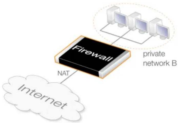
flowchart
graph TD
A["Firewall"] -->|NAT| B["Internet"]
A --> C["private network B"]
style A fill:#000,stroke:#fff,color:#fff
style B fill:#fff,stroke:#000
style C fill:#fff,stroke:#000
Figure 8.6. An Automatic NAT Address Translation Scenario
In the diagram above, the following types of traffic flows need to be allowed:
- The internal clients on the IPv4 network B need access to any other private IP address.
Automatic translation always allows traffic between private IPv4 addresses without applying any translation. - The internal clients on the network B need access to the Internet so they require NAT translation of their private IPv4 address to the public IPv4 address of the firewall interface connected to the Internet. Automatic translation always applies NAT translation when a private IPv4 address tries to connect to a public IPv4 address.
All the above requirements or combinations of them can be met using a single IP policy with automatic translation enabled. How to configure this is shown in the example below.
Example 8.13. Automatic NAT Translation with an IP Policy
This example shows how the automatic translation option in a single IP policy can be used so that HTTP/HTTPS clients on lan-net with private IP addresses are connected using automatic NAT translation to the Internet via a the single public IP address wan_ip. The diagram below illustrates this scenario.
The value for Source Translation defaults to Auto but in these examples it is explicitly stated for clarity.
Command-Line Interface
Create an IP policy with automatic translation:
gw-world:/> add IPPolicy Name=http_auto_nat_policy
SourceInterface=lan
SourceNetwork=lan_net
DestinationInterface=wan
DestinationNetwork=all-nets
Service=http-all
Action=Allow
SourceAddressTranslation=Auto
Web Interface
Create an IP policy with automatic translation:
-
Go to: Policies > Firewalling > Main IP Rules > Add > IP Policy
-
Now enter:
-
Name: http_auto_nat_policy
-
Action: Allow
-
Under Filter enter:
-
Source Interface: Ian
- Source Network: lan_net
- Destination Interface: wan
-
Destination Network: all-nets
• Service: http-all -
Under Source Translation enter:
- Address Translation: Auto
- Click OK
8.5.2. NAT/SAT Translation
The diagram below illustrates a typical scenario where automatic NAT/SAT translation might be used. This extends the scenario discussed previously in Section 8.5.1, "NAT Only Translation" with the additional requirement that connections from the Internet to the firewall's public IP address require SAT translation of the destination address to the private IP address of the webserver.
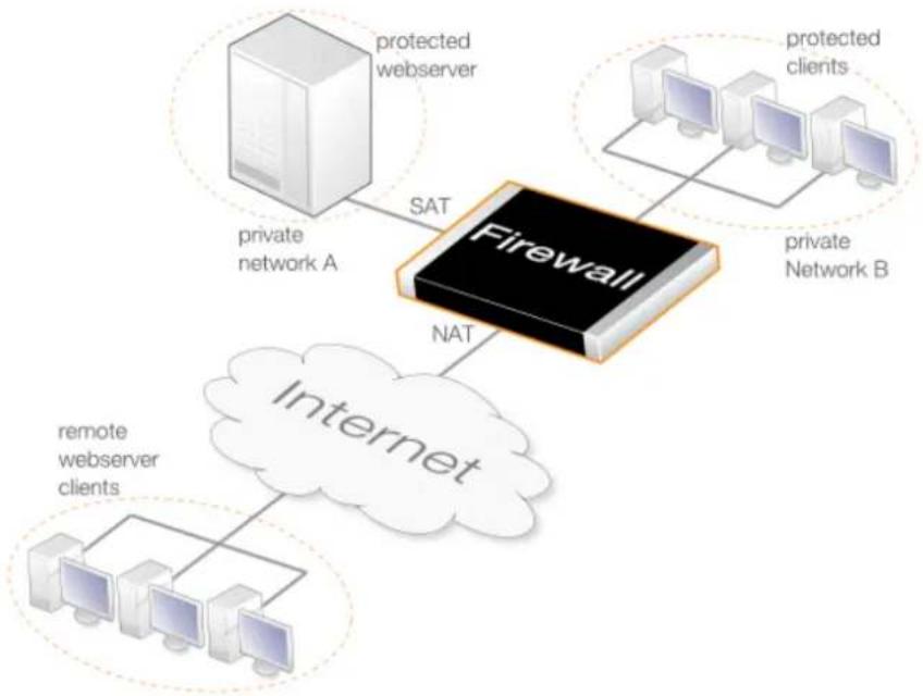
flowchart
graph TD
A["private network A"] -->|SAT| B["Firewall"]
C["protected webserver"] --> B
D["protected clients"] --> B
E["private Network B"] --> B
F["Internet"] -->|NAT| B
G["remote webserver clients"] --> F
Figure 8.7. An Automatic NAT/SAT Address Translation Scenario
In the diagram above, the following types of traffic flows need to be allowed:
- The internal clients on the IPv4 network B need access to any other private IP address.
Automatic translation always allows traffic between private IPv4 addresses without applying any translation.
• The internal clients on the network B need access to the Internet so they require NAT translation of their private IPv4 address to the public IPv4 address of the firewall interface connected to the Internet. Automatic translation always applies NAT translation when a private IPv4 address tries to connect to a public IPv4 address. - The webserver in the private IPv4 network A may be accessed by remote clients over the Internet using SAT translation of the firewall's public IP address. Automatic translation can be combined in the same IP policy with one-to-one SAT translation of the destination address to allow this.
- Internal clients on the private IPv4 network B also need to access the webserver via its public IP address. The NAT capability of automatic translation, which is mentioned in the second point above, will allow this.
All the above requirements or combinations of them can be met using a single IP policy with automatic translation enabled. How to configure this is shown in the example below.
Example 8.14. Automatic SAT/NAT Translation with an IP Policy
This example shows how a single IP policy with automatic translation enabled can be used so
that HTTP/HTTPS clients on both the Internet and lan-net can access a protected web server in the DMZ which has the private IPv4 address 10.0.0.5. Connections to the server will be made via the wan interface which has been assigned the public IP address wan_ip. SAT translation therefore needs to be applied so the destination IP address of connections to the server.
In addition, the clients on lan-net need access to the Internet via the wan interface.
Note that interface value of any and the address book value of all-nets are used in this example for simplicity but these could be narrowed for better security by creating the appropriate Interface Group and IP4 Address objects.
Command-Line Interface
gw-world:/> add IPPolicy Name=http_auto_satnat_policy
SourceInterface=any
SourceNetwork=all-nets
DestinationInterface=any
DestinationNetwork=wan_ip
Service=http-all
Action=Allow
SourceAddressTranslation=Auto
DestinationAddressTranslation=SAT
DestinationAddressAction=SingleIP
DestNewIP=10.0.0.5
Web Interface
-
Go to: Policies > Firewalling > Main IP Rules > Add > IP Policy
-
Now enter:
• Name: http_auto_satnat_policy
- Action: Allow
-
Under Filter enter:
-
Source Interface: any
- Source Network: all-nets
- Destination Interface: any
-
Destination Network: wan_ip
• Service: http-all -
Under Source Translation enter:
- Address Translation: Auto
-
Under Destination Translation enter:
-
Address Translation: SAT
• Address Action: Single IP -
New IP Address: 10.0.0.5
-
Click OK

Clients and server can be on the same network
It should be noted that the above example would allow not allow not only clients on the DMZ to access the webserver via its public IP address but also clients that are the same network as the webserver.
Chapter 9: User Authentication
This chapter describes how NetDefendOS implements user authentication.
• Overview, page 712
• Authentication Setup, page 715
- Customizing Authentication HTML, page 738
• IP Policies Requiring Authentication, page 742
- Brute Force Protection, page 744
- User Identity Awareness, page 746
• Multi Factor Authentication, page 751
- Radius Relay, page 753
• RADIUS Accounting, page 760
9.1. Overview
In situations where individual users connect to protected resources through the D-Link firewall, the administrator will often require that each user goes through a process of authentication before access is allowed.
This chapter deals with setting up authentication for NetDefendOS but first the general issues involved in authentication will be examined.
Proving Identity
The aim of authentication is to have the user prove their identity so that the network administrator can allow or deny access to resources based on that identity. Possible types of proof could be:
A. Something the user is. Unique attributes that are different for every person, such as a fingerprint.
B. Something the user has, such a passcard, a X.509 Digital Certificate or Public and Private Keys.
C. Something the user knows such as a password.
Method A may require a special piece of equipment such as a biometric reader. Another problem with A is that the special attribute often cannot be replaced if it is lost.
Methods B and C are therefore the most common means of identification in network security. However, these have drawbacks: keys might be intercepted, passcards might be stolen, passwords might be guessable, or people may simply be bad at keeping a secret. Methods B and C are therefore sometimes combined, for example in a passcard that requires a password or pin code for use.
Making Use of Username/Password Combinations
This chapter deals specifically with user authentication performed with username/password combinations that are manually entered by a user attempting to gain access to resources. Access to the external Internet through a D-Link firewall by internal clients using the HTTP protocol is an example of this.
In using this approach, username/password pairs are often the subject of attacks using guesswork or systematic automated attempts. To counter this, any password should be carefully chosen. Ideally it should:
- Be more than 8 characters with no repeats. The longer the better.
• Use random character sequences not commonly found in phrases. - Contain both lower and upper case alphabetic characters.
- Contain both digits and special characters.
To remain secure, passwords should also:
• Not be recorded anywhere in written form.
• Never be revealed to anyone else.
- Changed on a regular basis such as every three months.
Authentication Processing in NetDefendOS
The following steps describe the processing flow through NetDefendOS for username/password authentication:
- A user creates a new connection to the D-Link firewall.
-
NetDefendOS sees the new user connection on an interface and checks the Authentication rule set to see if there is a matching Authentication Rule for traffic on this interface, coming from this network and is one of the following types of connection:
-
HTTP traffic
- HTTPS traffic
- IPsec tunnel traffic
• L2TP tunnel traffic - PPTP tunnel traffic
- SSL VPN tunnel traffic
- If no authentication rule matches, the connection may be allowed, provided that the IP rule set permits it and nothing further happens in the authentication process.
- Based on the settings of the first matching authentication rule, NetDefendOS may prompt the user with an authentication request which requires username/password credentials to be entered.
- NetDefendOS validates the given credentials against the Authentication Source specified in the authentication rule. This will be either a local NetDefendOS database, an external RADIUS database server or an external LDAP server.
- NetDefendOS then allows further traffic through this connection as long as authentication was successful and the service requested is allowed by an IP rule set entry. That rule's Source Network object has either the No Defined Credentials option enabled or alternatively it is associated with a group and the user is also a member of that group.
- If a timeout restriction is specified in the authentication rule then the authenticated user will be automatically logged out after that length of time without activity.
Any packets from an IP address that fails authentication are discarded.
The sections that follows explain in detail the components and setup for authentication.
9.2. Authentication Setup
9.2.1. Authentication Setup Summary
The following list summarizes the steps for user authentication setup with NetDefendOS:
- Have an authentication source which consists of a database of users, each with a username/password combination. Any of the following can be an authentication source:
i. A local user database internal to NetDefendOS.
ii. A RADIUS server which is external to the D-Link firewall.
iii. An LDAP Server which is also external to the firewall.
- Define an Authentication Rule which describes which traffic passing through the firewall is to be authenticated and which authentication source will be used to perform the authentication. These are described further in Section 9.2.5, "Authentication Rules".
- If required, define an IP object for the IP addresses of the clients that will be authenticated. This can be associated directly with an authentication rule as the originator IP or can be associated with an Authentication Group.
- Set up IP rule set entries to allow the authentication to take place and also to allow access to resources by the clients belonging to the IP object set up in the previous step.
The sections that follow describe the components of these steps in detail. These are:
• Section 9.2.2, "Local User Databases"
• Section 9.2.3, "External RADIUS Servers"
• Section 9.2.4, "External LDAP Servers"
• Section 9.2.5, "Authentication Rules"
9.2.2. Local User Databases
A Local User Database is a registry internal to NetDefendOS which contains the profiles of authorized users and user groups. Combinations of usernames/password can be entered into these with passwords stored using reversible cryptography for security. By default, a single local user database exists called AdminUsers. Extra databases can be created by the administrator as required.
Username/Password Length Limits
Each user in a local user database will have a username and password with the following length restrictions:
• Maximum username length: 31 characters.
• Maximum password length: 72 bytes.
Note that the maximum password length is given as bytes and not characters. This is because a special character could use up 2 bytes of the 72 byte limit.
Example 9.1. Creating a Local User Database
This example shows how to create a new user database called lan_users.
Command-Line Interface
gw-world:/> add LocalUserDatabase lan_users
Web Interface
-
Go to: System > Device > Local User Databases > Add > LocalUserDatabase
-
Now enter:
-
Name: lan_users
• Comments: Ian auth group -
Click OK
Group Membership
Each User object added to a local database can optionally be specified to be a member of one or more authentication groups. This is done by specifying one or more group names for the Group property of the User object.
Only two groups are already defined in NetDefendOS and they have the group names administrators and the auditors. The privileges given to these groups are described later in the section. A new group is not explicitly created as a separate configuration object. Instead, it is implicitly created when a group name is associated with the user.
Group names created by the administrator have the following constraints:
- Group names are entered as text strings which are case sensitive and can have a maximum length of 128 characters.
• The only characters that cannot be used in a group name are spaces and commas. - The only limit on the number of group names is the number of unique combinations that can be created from 128 characters.
- Where a user is a member in multiple groups, the group names are entered as a comma delimited list. For example: group1, group2, group3.
Example 9.2. Adding a User with Group Membership
This example shows how to add a new user to the local database called lan_users. The name of the user will be myusername with the password myuserpassword and with membership in the two groups lan_group and employees.
Command-Line Interface
Change the CLI context to be the local database:
gw-world:/> cc LocalUserDatabase lan_users
Now, add a user to this database:
gw-world:/lan_users> add User myusername
Password=myuserpassword
Groups=lan_group,employees
After adding any additional users, change the context back to the default:
gw-world:/lan_users> cc
gw-world:/>
Web Interface
- Go to: System > Device > Local User Databases
- Select lan_users
- Select Users then Add > User
-
Now enter:
-
Name: myusername
- Password: myuserpassword
- Confirm Password: myuserpassword
-
Groups: Ian_group, employees
-
Click OK
Administrators and Auditors Group Membership
When a new user is defined, it can optionally be given membership in one of the following default groups:
• The administrators group
Members of this group can log into NetDefendOS through the Web Interface as well as through the remote CLI interface and are allowed to edit the NetDefendOS configuration. Only one user can be logged in with administrator privileges at once (although that single administrator can be logged in with more than one simultaneous session).
• The auditors group
This is similar to the administrators group but members are only allowed to view the configuration data but cannot change it. Any number of audit users can be logged in at once.
Using Authentication Groups with IP Rule Sets
Authentication groups are not used directly with Authentication Rule objects but are instead associated with the source network or destination network IP object used in the IP rule set entry that allows the traffic.
When specifying the Source Network for an IP rule set entry, a user defined IP address object can be used where the Authentication Group property for that address object has been specified. This will mean that the IP rule set entry will then only apply to logged-in clients who also belong to the source network's associated authentication group.
Alternatively, the Destination Network could be used so that only authenticated servers are available to clients. Authentication of a server is achieved by opening a single connection once to NetDefendOS as though the server were a client.
The result of doing either is to restrict access to given networks by having IP rule set entries that will only apply to members of certain groups. To gain access to a network there must be an IP rule set entry that allows it and the client must belong to the same group as that specified for the Source Network or Destination Network address object.
For an example of setting up user authentication using group membership, see Example 9.4, "User Authentication Setup for Web Access" which is found later in this section.
PPTP/L2TP Configuration
If a client is connecting to the D-Link firewall using PPTP/L2TP then the following three options can also be specified for entries in the local NetDefendOS user database chosen as the authentication source:
- Static Client IP Address
This is the IP address which the client must have if it is to be authenticated. If it is not specified then the user can have any IP. This option offers extra security for users with fixed IP addresses.
• Network behind user
If a network is specified for this user then when the user connects, a route is automatically added to the NetDefendOS main routing table. This existence of this added route means that any traffic destined for the specified network will be correctly routed through the user's PPTP/L2TP tunnel.
When the connection to the user ends, the route is automatically removed by NetDefendOS.

Caution: Use the network option with care
The administrator should think carefully what the consequences of using this option will be. For example, setting this option to all-nets will possibly direct all Internet traffic through the tunnel to this user.
• Metric for Networks
If the Network behind user option is specified then this is the metric that will be used with the route that is automatically added by NetDefendOS. If there are two routes which give a match for the same network then this metric decides which should be used.

Note: Other authentication sources do not have the PPTP/L2TP option
Specifying an SSH Public Key
With PPTP/L2TP clients, using a key is often an alternative to specifying a username and password. A private key can be specified for a local database user by selecting a previously uploaded NetDefendOS SSH Client Key object.
When the user connects, there is an automatic checking of the keys used by the client to verify their identity. Once verified, there is no need for the user to input their username and password.
To make use of this feature, the relevant SSH Client Key object or objects must first be defined separately in NetDefendOS. Client keys are found as an object type within Key Ring in the Web Interface. Definition requires the uploading of the public key file for the key pair used by the client.
9.2.3. External RADIUS Servers
Reasons for Using External Servers
In a larger network topology with a larger administration workload, it is often preferable to have a central authentication database on a dedicated server. When there is more than one D-Link firewall in the network and thousands of users, maintaining separate authentication databases on each device becomes problematic. Instead, an external authentication server can validate username/password combinations by responding to requests from NetDefendOS. To provide this, NetDefendOS supports the Remote Authentication Dial-in User Service (RADIUS) protocol.
RADIUS Usage with NetDefendOS
NetDefendOS can act as a RADIUS client, sending user credentials and connection parameter information as a RADIUS message to a designated RADIUS server. The server processes the requests and sends back a RADIUS message to accept or deny them. One or more external servers can be defined in NetDefendOS.
RADIUS Security
To provide security, a common shared secret is configured on both the RADIUS client and the server. This secret enables encryption of the messages sent from the RADIUS client to the server and is commonly configured as a relatively long text string. The string can contain up to 128 characters and is case sensitive.
RADIUS uses PPP to transfer username/password requests between client and RADIUS server, as well as using PPP authentication schemes such as PAP and CHAP. RADIUS messages are sent as UDP messages via UDP port 1812.
The Primary Retry Interval
The Primary Retry Interval property for an Authentication Interval object, specifies the behavior after the primary RADIUS server is unresponsive and a secondary server is used instead. If the
Primary Retry Interval is set to zero, the selected secondary server will continue to be used even through the primary server may become available later.
If set, the Primary Retry Interval property specifies the number of seconds to wait before NetDefendOS tries to reach the primary server again. These retries will continue indefinitely. If the primary server becomes available, NetDefendOS will immediately switch back to it from the secondary.
Setting the Source IP
By default, the Source IP property will be set to Automatic and the IP address of the firewall's sending interface will be used as the source address for traffic sent to the RADIUS server. If this property is set to Manual, a specific source IP address can be used for traffic sent to the server.
If the source IP address is specified, the administrator must also manually configure NetDefendOS to ARP publish the IP address on the sending interface. Doing this is described in Section 3.5.3, "ARP Publish".
Support for Groups
RADIUS authentication supports the specification of groups for a user. This means that a user can also be specified as being in the administrators or auditors group.

Note: Set the RADIUS Vendor ID for group membership
If the RADIUS server is required to send the group membership, it is necessary to use the user group vendor specific attribute vendor when configuring the server. The NetDefendOS Vendor ID is 5089 and the user group is defined as vendor-type 1 with a string value type.
Support for IPv4 and IPv6
The IP address of a RADIUS server that is configured in NetDefendOS can be either an IPv4 address or an IPv6 address.
Automatic IP Address Allocation
With IPsec, L2TP and PPTP tunnels for roaming clients, it is possible for NetDefendOS to automatically allocate IP addresses as part of the RADIUS authentication process.
Depending on how it is configured, a RADIUS server can optionally return IP address information to NetDefendOS in its Access-Accept message when it authenticates a client. NetDefendOS will automatically recognize and use the following parameters in a RADIUS Accept-Access message:
- Framed-IP-Address
This parameter is an IP address allocated for the client which NetDefendOS automatically will send to the connecting client as a part of the tunnel negotiation.
- Framed-IP-Netmask
In some cases, the client might be a network device, such as another firewall with a network behind it. The Framed-IP-Netmask parameter requires that the Framed-IP-Address is also present in the Access-Accept message. The netmask together with the IP address is combined to form a route which will be sent to the client as a part of the tunnel negotiation as a definition of the network behind the client.
- Framed-Route
This can be sent by the RADIUS server instead of Framed-IP-Address and Framed-IP-Netmask. The route will be sent to the client as a part of the tunnel negotiation as a definition of the network behind the client.
This IP address information will be automatically sent to the client in either of the following ways:
• During the IKE negotiation phase of IPsec tunnel setup.
• Over PPP when setting up an L2TP or PPTP tunnel.
In addition, NetDefendOS will automatically add a route to its configuration if either the Framed-IP-Address, Framed-Route or the Framed-IP-Address along with Framed-IP-Netmask parameter is received. The automatic addition of this route can be controlled in the normal way by setting the relevant property in the tunnel object for the automatic addition of routes.
Example 9.3. Configuring a RADIUS Server
The following steps illustrate how a RADIUS server is configured. Assume that the NetDefendOS object will have the name rs_users and the IPv4 address radius_ip which is already defined in the address book.
The connecting port will be 1812 (the default) and a shared secret of mysecretcode will be used for security.
A retry timeout value of 2 means that NetDefendOS will resend the authentication request to the sever if there is no response after 2 seconds. There will be a maximum of 3 retries.
Command-Line Interface
gw-world:/> add RadiusServer rs_users
IPAddress=radius_ip
SharedSecret=mysecretcode
Port=1812
RetryTimeout=2
Web Interface
-
Go to: Policies > User Authentication > RADIUS > Add > RADIUS Server
-
Now enter:
-
Name: rs_users
- IP Address: radius_ip
• Port: 1812 - Retry Timeout: 2
- Shared Secret: mysecretcode
-
Confirm Secret: mysecretcode
-
Click OK
9.2.4. External LDAP Servers
Lightweight Directory Access Protocol (LDAP) servers can also be used with NetDefendOS as an authentication source. This is implemented by the D-Link firewall acting as a client to one or more LDAP servers. Multiple servers can be configured to provide redundancy if any servers become unreachable.
Setting Up LDAP Authentication
There are two steps for setting up user authentication with LDAP servers:
- Define one or more user authentication LDAP server objects in NetDefendOS.
- Specify one or a list of these LDAP server objects in a user authentication rule.
One or more LDAP servers can be associated as a list within a user authentication rule. The ordering of the list determines the order in which server access is attempted.
The first server in the list has the highest precedence and will be used first. If authentication fails or the server is unreachable then the second in the list is used and so on.
LDAP Issues
Unfortunately, setting up LDAP authentication may not be as simple as, for example, RADIUS setup. Careful consideration of the parameters used in defining the LDAP server to NetDefendOS is required. There are a number of issues that can cause problems:
- LDAP servers differ in their implementation. NetDefendOS provides a flexible way of configuring an LDAP server and some configuration options may have to be changed depending on the LDAP server software.
- Authentication of PPTP or L2TP clients may require some administrative changes to the LDAP server and this is discussed later.
Microsoft Active Directory as the LDAP Server
A Microsoft Active Directory can be configured in NetDefendOS as an LDAP server. There is one option in the NetDefendOS LDAP server setup which has special consideration with Active Directory and that is the Name Attribute. This should be set to SAMAccountName.
Due to LDAP protocol limitations, an LDAP user group set to primary cannot be received by NetDefendOS from the Microsoft LDAP server and used in security policies.
Defining an LDAP Server
One or more named LDAP server objects can be defined in NetDefendOS. These objects tell NetDefendOS which LDAP servers are available and how to access them.
Defining an LDAP server to NetDefendOS is sometimes not straightforward because some LDAP server software may not follow the LDAP specifications exactly. It is also possible that an LDAP administrator has modified the server LDAP schema so that an LDAP attribute has been renamed.
LDAP Attributes
To fully understand LDAP setup, it is important to note some setup values are attributes. These are:
- The Name attribute.
• The Membership attribute.
• The Password attribute.
An LDAP attribute is a tuple (a pair of data values) consisting of an attribute name (in this manual we will call this the attribute ID to avoid confusion) and an attribute value. An example might be a tuple for a username attribute that has an ID of username and a value of Smith.
These attributes can be used in different ways and their meaning to the LDAP server is usually defined by the server's database schema. The database schema can usually be changed by the server administrator to alter the attributes.
General Settings
The following general parameters are used for configuration of each server:
- Name
The name given to the server object for reference purposes in NetDefendOS. For example, NetDefendOS authentication rules may be defined which reference this name.
This value has nothing to do with the Name Attribute described below. It is only for use by NetDefendOS and not the LDAP server.
• IP Address
The IP address of the LDAP server.
• Port
The port number on the LDAP server which will receive the client request which is sent using TCP/IP.
The default port number is 389.
- Source IP Selection
By default (Automatic), the IP address of the firewall's sending interface will be used as the source address for traffic sent to the LDAP server. If this property is set to Manual, a specific source IP address can be specified.
If a specific source IP address is specified, the administrator must also manually configure NetDefendOS to ARP publish the IP address on the sending interface. Doing this is described in Section 3.5.3, "ARP Publish".
The default value is Automatic.
- Timeout
This is the timeout length for LDAP server user authentication attempts in seconds. If no response to a request is received from the server after this time then the server will be considered to be unreachable.
The default timeout setting is 5 seconds.
- Name Attribute
The Name Attribute is the ID of the data field on the LDAP server that contains the username. The NetDefendOS default value for this is uid which is correct for most UNIX based servers.
If using Microsoft Active Directory this should be set to SAMAccountName (which is NOT case sensitive). When looking at the details of a user in Active Directory, the value for the user login name is defined in the SAMAccountName field under the Account tab.

Note: The LDAP server database determines the correct value
This is an attribute tuple and the LDAP server's database schema definitions determines the correct ID to use.
- Retrieve Group Membership
This option specifies if the groups that a user belongs to should be retrieved from the LDAP server. The group name is often used when granting user access to a service after a successful login.
If the Retrieve Group Membership option is enabled then the Membership Attribute option, described next can also be set.
- Membership Attribute
The Membership Attribute defines which groups a user is a member of. This is similar to the way a user belongs to either the admin or audit database group in NetDefendOS. This is another tuple defined by the server's database schema and the default ID is MemberOf.
In Microsoft Active Directory, the groups a user belongs to can be found by looking at a user's details under the MemberOf tab.
- Use Domain Name
Some servers require the domain name in combination with a username for performing successful authentication. The domain name is the host name of the LDAP server, for example myldapserver. The choices for this parameter are:
i. Do Not Use - This will not modify the username in any way. For example, testuser.
ii. Username Prefix - When authenticating, this will put
iii. Username Postfix - When authenticating, this will add @
If the choice is other than Do Not Use, the Domain Name parameter option described below should be specified.
Different LDAP servers could handle the domain name differently so the server's requirements should be checked. Most versions of Windows Active Directory require the Postfix option to be used.
When using the OpenLDAP server and with most non-Microsoft LDAP servers, this property should be set to Do not use and the next property Combined User Name should be enabled.
• Combined User Name
When using the OpenLDAP server, the Use Domain Name property should be set to Do not use and this property should be enabled. Other non-Microsoft LDAP servers will probably also require that this option be enabled.
- Optional Attribute
If the Combined User Name property is enabled, it is also possible to use this property to specify an optional text attribute to be sent to the server. For example, if this property is set to:
ou=people
This is inserted between the name and the base objects. For example, the resulting attributes might now become:
uid=someuser,ou=people,dc=somedomain,dc=com
- Routing Table
The NetDefendOS routing table where route lookup will be done to resolve the server's IP address into a route. The default is the main routing table.
Database Settings
The Database Settings are as follows:
- Base Object
Defines where in the LDAP server tree search for user accounts shall begin.
The users defined on an LDAP server database are organized into a tree structure. The Base Object specifies where in this tree the relevant users are located. Specifying the Base Object has the effect of speeding up the search of the LDAP tree since only users under the Base Object will be examined.

Important: The Base Object must be specified correctly
If the Base Object is specified incorrectly then this can mean that a user will not be found and authenticated if they are not in the part of the tree below the Base Object. The recommended option is therefore to initially specify the Base Object as the root of the tree.
The Base Object is specified as a comma separated domainComponent (DC) set. If the full domain name is myldapserver.local.eu.com and this is the Base Object then this is specified as:
DC=myldapserver, DC=local, DC=eu, DC=com
The username search will now begin at the root of the myldapserver tree.
- Administrator Account
The LDAP server will require that the user establishing a connection to do a search has administrator privileges. The Administration Account specifies the administrator username. This username may be requested by the server in a special format in the same way as described previously with Use Domain Name.
- Password/Confirm Password
The password for the administrator account which was specified above.
- Domain Name
The Domain Name is used when formatting usernames. This is the first part of the full domain name. In the examples above, the Domain Name is myldapserver. The full domain name is a dot separated set of labels, for example, myldapserver.local.eu.com.
This option is only available if the Server Type is NOT set to Other.
This option can be left empty but is required if the LDAP server requires the domain name when performing a bind request.
Optional Settings
There is one optional setting:
- Password Attribute
The password attribute specifies the ID of the tuple on the LDAP server that contains the user's password. The default ID is userPassword.
This option should be left empty unless the LDAP server is being used to authenticate users connecting via PPP with CHAP, MS-CHAPv1, MS-CHAPv2 or when using SSL VPN.
When it is used, it determines the ID of the data field in the LDAP server database which contains the user password in plain text. The LDAP server administrator must make sure that this field actually does contain the password. This is explained in greater detail later.
When LDAP is used with SSL VPN, the Password Attribute must be specified as userPassword or Description based on the setting for the Agent option in the user authentication rule object.
Bind Request Authentication
LDAP server authentication is automatically configured to work using LDAP Bind Request Authentication. This means that authentication succeeds if successful connection is made to the LDAP server. Individual clients are not distinguished from one another.
LDAP server referrals should not occur with bind request authentication but if they do, the server sending the referral will be regarded as not having responded.
LDAP Server Responses
When an LDAP server is queried by NetDefendOS with a user authentication request, the following are the possible outcomes:
• The server replies with a positive response and the user is authenticated.
Clients using PPP with CHAP, MS-CHAPv1 or MS-CHAPv2 is a special case and authentication is actually done by NetDefendOS, as discussed later.
• The server replies with a negative response and the user is not authenticated.
- The server does not respond within the Timeout period specified for the server. If only one server is specified then authentication will be considered to have failed. If there are alternate servers defined for the user authentication rule then these are queried next.
Usernames may need the Domain
With certain LDAP servers, the domain name may need to be combined with the username when the user is prompted for a username/password combination.
If the domain is mydomain.com then the username for myuser might need to be specified as myuser@mydomain.com. With some LDAP servers this might be myuser@domain mydomain.com\myuser or even mydomain\myuser. The format depends entirely on the LDAP server and what it expects.
Real-time Monitoring Statistics
The following statistics are available for real-time monitoring of LDAP server access for user authentication:
• Number of authentications per second.
• Total number of authentication requests.
• Total number of successful authentication requests.
• Total number of failed authentication requests.
• Total number of invalid usernames.
• Total number of invalid password.
LDAP Authentication CLI Commands
The CLI objects that correspond to LDAP servers used for authentication are called LDAPDatabase objects (LDAP servers used for certificate lookup are known as LDAPServer objects in the CLI).
A specific LDAP server that is defined in NetDefendOS for authentication can be shown with the command:
gw-world:/> show LDAPDatabase <object_name>
The entire contents of the database can be displayed with the command:
gw-world:/> show LDAPDatabase
LDAP Authentication and PPP
When using a PPP based client for PPTP or L2TP access, special consideration has to be taken if
LDAP authentication is to succeed with CHAP, MS-CHAPv1 or MS-CHAPv2 encryption. The two cases of (A) normal PPP authentication and (B) PPP with encryption are examined next.
A. Normal LDAP Authentication
Normal LDAP authentication for Webauth, XAuth, or PPP with PAP security is illustrated in the diagram below. An authentication bind request with the username and password is sent to the LDAP server which then performs the authentication and sends back a bind response with the result.
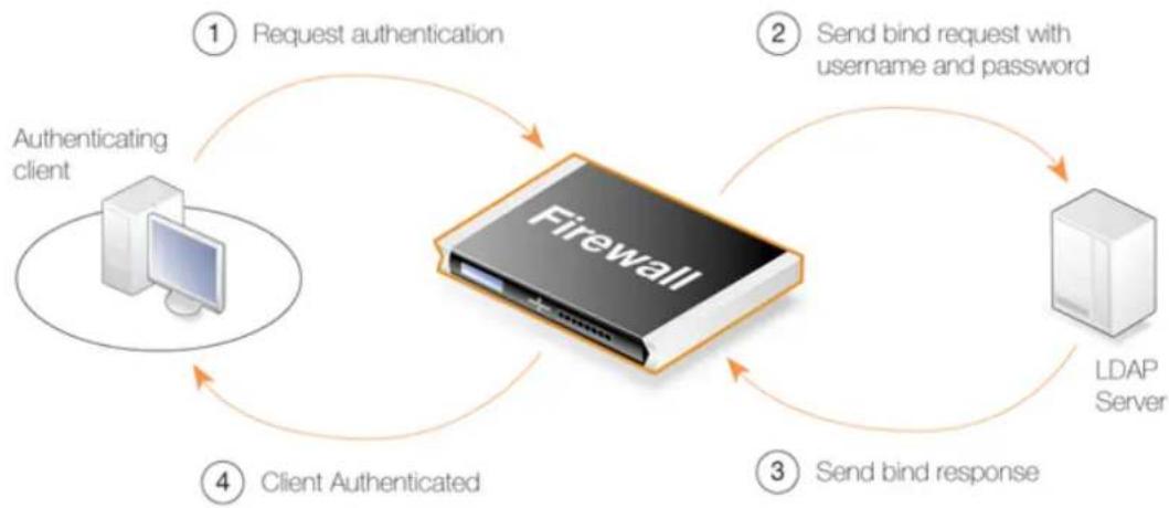
flowchart
graph TD
A["Authentication client"] -->|① Request authentication| B["Firewall"]
B -->|② Send bind request with username and password| C["LDAP Server"]
C -->|③ Send bind response| B
B -->|④ Client Authenticated| A
Figure 9.1. Normal LDAP Authentication
The processing is different if a group membership is being retrieved since a request is sent to the LDAP server to search for memberships and any group memberships are then sent back in the response.
B. PPP Authentication with CHAP, MS-CHAPv1 or MS-CHAPv2 Encryption
If PPP with CHAP, MS-CHAPv1 or MS-CHAPv2 is used for authentication, a digest of the user's password will be sent to NetDefendOS by the client. NetDefendOS cannot just forward this digest to the LDAP server since this will not be understood. The solution is for NetDefendOS to obtain the password in plain-text from the LDAP server, create a digest itself, and then compare the created digest with the digest from the client. If the two are the same, authentication is successful but it is NetDefendOS that makes the authentication decision and not the LDAP server.
To retrieve the password from the LDAP server, two things are needed:
- The Password Attribute parameter needs to be specified when defining the server to NetDefendOS. This will be the ID of the field on the LDAP server that will contain the password when it is sent back.
This ID must be different from the default password attribute (which is usually userPassword for most LDAP servers). A suggestion is to use the description field in the LDAP database.
• In order for the server to return the password in the database field with the ID specified, the LDAP administrator must make sure that the plain text password is found there. LDAP servers store passwords in encrypted digest form and do not provide automatic mechanisms for doing this. It must therefore be done manually by the administrator as they add new users and change existing users passwords.
This clearly involves some effort from the administrator, as well as leaving passwords dangerously exposed in plain text form on the LDAP server. These are some of the reasons why LDAP may not be viewed as a viable authentication solution for CHAP, MS-CHAPv1 or
MS-CHAPv2 encrypted PPP.
When NetDefendOS receives the password digest from the client, it initiates a Search Request to the LDAP server. The server replies with a Search Response which will contains the user's password and any group memberships. NetDefendOS is then able to compare digests. The diagram below illustrates this process.
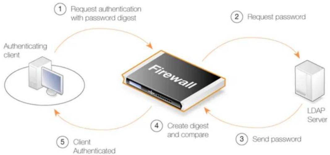
flowchart
graph TD
A["Authentication client"] -->|① Request authentication with password digest| B["Firewall"]
B -->|② Request password| C["LDAP Server"]
C -->|③ Send password| B
B -->|④ Create digest and compare| C
C -->|⑤ Client Authenticated| B
Figure 9.2. LDAP for PPP with CHAP, MS-CHAPv1 or MS-CHAPv2

Important: The link to the LDAP server must be protected
Since the LDAP server is sending back passwords in plain text to NetDefendOS, the link between the D-Link firewall and the server must be protected. A VPN link should be used if the link between the two is not local.
Access to the LDAP server itself must also be restricted as passwords will be stored in plain text.
9.2.5. Authentication Rules
An Authentication Rule should be defined when a client establishing a connection through a D-Link firewall is to be prompted for a username/password login sequence.
Authentication Rules are set up in a similar way to other NetDefendOS security policies, and that is by specifying which traffic is to be subject to the rule. They differ from other policies in that the connection's destination network/interface is not of interest but only the source network/interface of the client being authenticated.
Authentication Rule Properties
An Authentication Rule object has the following properties:
- Authentication Agent
The type of traffic being authenticated. This can be one of:
i. ARPCache
This sends the MAC address of the client's interface to a RADIUS server for authentication and is applicable to any type of traffic.
This option is explained further in Section 9.2.7, "MAC Authentication".
ii. HTTP
Allows HTTP web connections to be authenticated via a predefined or custom web page. This is the default value for the agent property and is described further in Section 9.2.6, "HTTP Authentication".
Note that an IP rule set entry allowing client access is required with this agent type. The Destination Interface for this entry must be core.
MAC authentication can also be performed using this option and this is explained further in Section 9.2.7, "MAC Authentication".
iii. HTTPS
Allows HTTPS web connections to be authenticated via a predefined or custom web page. This is also described further in Section 9.2.6, "HTTP Authentication".
Note that an IP rule allowing client access to core is also required with this agent type.
iv. XAUTH
This is the IKEv1 authentication method which is used as part of IPsec tunnel establishment. The client can have an IP address which is either IPv4 or IPv6.
XAuth is an extension to the normal IKE exchange which provides an additional security by requiring clients to provide credentials.
Note that an IP rule allowing client access to core is not required with this agent type.
v. L2TP/PPTP/SSL VPN
This is used specifically for L2TP, PPTP or SSL VPN authentication.
Note that an IP rule set entry allowing client access to the core interface is not required with this agent type.
Also note that the PPP Agent Options for the authentication rule can be changed when this agent type is selected. By default, the PAP, CHAP, MS-CHAP and MS-CHAPv2 options are enabled and the Allow no authentication option is disabled. For SSL VPN, only the PAP option should be left enabled.
vi. EAP
This is the IKEv2 authentication method which is used as part of IPsec tunnel establishment. It authenticates the IP address of the client, which can be an IPv4 or IPv6 address.
The Originator IP and Terminator IP are not configurable with this method since they are already defined on an associated IPsec Tunnel object as the Local Endpoint and the Remote Endpoint.
Note that an IP rule set entry allowing client access to the core interface is not required with this agent type.
- Authentication Source
This specifies that authentication is to be performed using one of the following:
i. LDAP - Users are looked up in an external LDAP server database. Using LDAP servers is described further in Section 9.2.4, "External LDAP Servers".
ii. RADIUS - An external RADIUS server is used for lookup. Using RADIUS servers is described further in Section 9.2.3, "External RADIUS Servers".
iii. Disallow - This option explicitly disallows all connections that trigger this rule. Such connections will never be authenticated.
Any Disallow rules are best located at the end of the authentication rule set.
iv. Local - Users are looked up in a NetDefendOS local user database. Local user databases are described further in Section 9.2.2, "Local User Databases".
v. Allow - With this option, all connections that trigger this rule will be authenticated automatically. No database lookup occurs.
- Interface
The source interface on which the connections to be authenticated will arrive. This property must be specified and allows different rules to be associated with different interfaces. With a source of XAuth or EAP, the interface would be the IPsec tunnel name. However, a value of any can always be specified to associate a rule with all interfaces.
- Originator IP
The source IP or network from which new connections will arrive. For PPP this will be the Originator IP. This is not specified in the rule for XAuth or EAP as it is the Local Endpoint of the IPsec tunnel.
- Terminator IP
The terminating IP with which new connections arrive. This is only specified where the Authentication Agent is PPP. This is not specified in the rule for XAuth or EAP as it is the Remote Endpoint of the IPsec tunnel.
Connection Timeouts
An Authentication Rule can specify the following timeouts related to a user session:
- Idle Timeout
How long a connection is idle before being automatically terminated (1800 seconds by default).
- Session Timeout
The maximum time that a connection can exist (no value is specified by default).
If an authentication server is being used then the option to Use timeouts received from the authentication server can be enabled to have these values set from the server.
Multiple Logins
An Authentication Rule can specify how multiple logins are handled where more than one user from different source IP addresses try to login with the same username. The possible options are:
- Allow multiple logins per username.
Allow multiple logins so that more than one client can use the same username/password combination.
- Allow only one login per username, disallow the rest.
Allow only one login per username.
- Allow only one login per username, disallow the rest without exception. (strict)
This option deals with the specific case of an IKEv1 IPsec client that performs an IKE rekey operation. With some client software, the client is not logged out with the rekey so that NetDefendOS thinks that a second authentication with the same username is being performed. The previous option allows this to take place. This option will not allow authentication after an IKE rekey with the same credentials if the client has not first logged itself out.
- Allow one login per username.
Only one login per username is allowed. A second login attempt with the same username will be successful only if the existing user can by logged out and this will only happen if they have been idle for a specific length of time.
The idle time default is 10 seconds but this value can be changed.
9.2.6. HTTP Authentication
The general term HTTP authentication is used in this publication to refer to authentication related to both the HTTP and HTTPS protocols. Where users are communicating through a web browser using the HTTP or HTTPS, authentication is often performed by NetDefendOS presenting the user with HTML pages to retrieve the required user credential information. This is sometimes also referred to as WebAuth. HTTP/HTTPS authentication setup requires further considerations which are discussed in this section.
The Management Web Interface Port May Need To Be Changed
If HTTP authentication is going to be applied to users connecting via the NetDefendOS management Ethernet interface then it will collide with the Web Interface's remote management service which, by default, also uses TCP port 80 (for HTTP) and 443 (for HTTPS) by default. To avoid this problem, the Web Interface port number must be changed before configuring HTTP authentication.
This is done by going to System > Remote Management > Advanced settings in the Web Interface and changing the settings WebUI HTTP port and WebUI HTTPS port. For example, the HTTP port number could be changed to 81.
HTTP and HTTPS Agent Options
For HTTP and HTTPS authentication there is a set of properties in an authentication rule called Agent Options. Among these options are the following related to HTTP/HTTPS:
- Login Type - This can be one of:
i. HTML form - The user is presented with an HTML page for authentication which is filled in and the data sent back to NetDefendOS with a POST.
ii. BASIC authentication - This sends a 401 - Authentication Required message back to the browser which will cause it to use its own inbuilt dialog to ask the user for a username/password combination. A Realm String will appear in the browser's dialog to identify the source of the 401 message. The default value for this is admin and this can be changed by setting the Realm String property of the Authentication Rule object.
HTML form is recommended over BASICAUTH because, in some cases, the browser might hold the login data in its cache.
iii. MAC authentication - Authentication is performed for HTTP and HTTPS clients without a login screen. Instead, the MAC address of the connecting client is used as the username. The password is the MAC address or a specified string.
MAC authentication is explained further in Section 9.2.7, "MAC Authentication".
- If the Agent is set to HTTPS then the Host Certificate and Root Certificate(s) have to be chosen from a list of certificates already loaded into NetDefendOS. Certificate chaining is supported for the root certificate.
IP Rule Set Entries are Needed
HTTP and HTTPS authentication cannot function unless an entry is added to the IP rule set to explicitly allow authentication to take place.
Consider the example of a number of clients on the local network lannet who would like access to the Internet through the wan interface. To allow authentication of these clients, the IP rule set should contain the following entries:
| # | Action | Src Interface | Src Network | Dest Interface | Dest Network | Service |
| 1 | Allow | lan | lannet | core | lan_ip | http-all |
| 2 | Allow/NAT | lan | trusted_users | wan | all-nets | http-all |
| 3 | Allow/NAT | lan | lannet | wan | all-nets | dns-all |
The first rule allows the authentication process to take place and assumes the client is trying to access the lan_ip IP address, which is the IP address of the interface on the D-Link firewall where the local network connects.
The second rule allows normal surfing activity but lannet cannot be used as the source network since the rule would trigger for any unauthenticated client from that network. Instead, the source network is an administrator defined IP object called trusted_users which is the same network as lannet but has additionally either the Authentication option No Defined Credentials enabled or has an Authentication Group assigned to it (which is the same group as that assigned to the users).
The third rule allows DNS lookup of URLs.

Note: Do not alter predefined service objects
Do not modify the predefined http-all service which is used in the IP rule set entries above. This can cause authentication to fail.
Forcing Users to a Login Page
With this setup, when users that are not authenticated try to surf to any IP except lan_ip they will fall through the IP rules and their packets will be dropped. To always have these users come to the authentication page, a SAT rule set entry must be added. The rule set will now look like this:
| # | Action | Src Interface | Src Network | Dest Interface | Dest Network | Service |
| 1 Allow lan lannet core lan_ip http-all | ||||||
| 2 | Allow/NAT | lan | trusted_users | wan | all-nets | http-all |
| 3 | Allow/NAT | lan | lannet | wan | all-nets | dns-all |
| 4 Allow/SAT | Ian lannet wan | all-nets | all-to-one127.0.0.1 | http-all | ||
The SAT entry catches all unauthenticated requests and must be set up with an all-to-one address mapping that directs them to the address 127.0.0.1 which corresponds to core (NetDefendOS itself).
Example 9.4. User Authentication Setup for Web Access
The configurations below shows how to enable HTTP user authentication for the user group lan_group on lannet. Only users that belong to the group users can get Web browsing service after authentication, as it is defined in the IP policy.
It is assumed that the authentication IPv4 address object lan_users_net has been defined and this has its Groups property set to lan_group. The group lan_group has been used as the Groups property of individual users in the lan_users database.
Command-Line Interface
A. Set up an IP policy to allow HTTP authentication:
gw-world:/> add IPolicy Name=http_auth
SourceInterface=lan
SourceNetwork=lannet
DestinationInterface=core
DestinationNetwork=lan_ip
Service=http-all
Action=Allow
B. Set up an authentication rule:
gw-world:/> add UserAuthRule Name=http_auth
AuthSource=Local
Interface=lan
OriginatorIP=lannet
LocalUserDB=lan_users
LoginType=HTMLForm
Note that the Agent property has a default value of HTTP.
C. Set up an IP policy to allow authenticated users to browse the Internet:
gw-world:/> add IPolicy Name=allow_http_auth
SourceInterface=lan
SourceNetwork=lan_users_net
DestinationInterface=wan
DestinationNetwork=all-nets
Service=http-all
Action=Allow
SourceAddressTranslation=NAT
NATSourceAddressAction=OutgoingInterfaceIP
Web Interface
A. Set up an IP policy to allow HTTP authentication:
-
Go to: Policies > Firewalling > Main IP Rules > Add > IP Policy
-
Now enter:
-
Name: http_auth
-
Action: Allow
-
Under Filter enter:
-
Source Interface: Ian
• Source Network: Iannet - Destination Interface core
-
Destination Network lan_ip
• Service: http-all -
Click OK
B. Set up an authentication rule:
-
Go to: Policies > User Authentication > Authentication Rules > Add > User Authentication Rule
-
Now enter:
-
Name: http_login
• Authentication Agent: HTTP
• Authentication Source: Local - Interface: lan
-
Originator IP: lannet
-
Under Authentication Options enter:
-
Local User DB: lan_users
Under Agent Options enter: -
Login Type: HTML form
-
Click OK
C. Set up an IP policy to allow authenticated users to browse the Internet:
-
Go to: Policies > Firewalling > Main IP Rules > Add > IP Policy
-
Now enter:
-
Name: allow_http_auth
• Action: Allow -
Under Filter enter:
-
Source Interface: Ian
- Source Network: lan_users_net
-
Destination Interface wan
• Destination Network all-nets
• Service: http-all -
Under Source Translation enter:
-
Address Translation: NAT
• Address Action: Outgoing Interface IP -
Click OK
9.2.7. MAC Authentication
MAC authentication (sometimes referred to as ARP authentication) is authentication based on the MAC address of a connecting client's Ethernet interface. This is useful if the administrator wants to ensure that access is simple for a particular device and the user will not be required to type in their credentials. NetDefendOS sends the MAC address of the connecting client to a RADIUS or LDAP server which then looks the MAC address up in its database and tells NetDefendOS if the client is authenticated or not. Note that using a local database with MAC authentication is not supported in NetDefendOS.
Setting Up MAC Authentication
MAC authentication can be configured in one of two ways:
• For HTTP or HTTPS traffic only
Create an Authentication Rule object with the Authentication agent set to HTTP or HTTPS and set the Login Type under Agent Options to be MAC authentication.
• For any type of traffic using ARP Cache
Create an Authentication Rule object with the User Agent property set to ARPCache and set the Authentication Source to be RADIUS or LDAP.
Unlike the previous method, this method can be used for any traffic but has the disadvantage of requiring further steps which are explained below.
Note that if the Authentication Source is set to Allow then all users will be automatically authenticated without reference to a database. The only advantage to doing this is that the
administrator can easily see a list of logged in users by going to: Status > Run-time Information > User Authentication in the Web Interface.
Other Required Steps with the ARP Cache Method
When using the ARP Cache method, the following configuration steps are needed so that the NetDefendOS ARP cache contains the data needed for successful authentication:
- Below the IP rule set entry that allows the authenticated traffic, there must be a second entry which triggers on the same traffic but has the action Deny plus the deny behavior Reject. This ensures that clients that are not yet authenticated will still have their MAC addresses placed into the ARP cache. If the second rule set entry is not present, authentication will not work.
- The time between ARP cache refreshes should be adjusted downwards so that should a connection be broken, for instance by an idle timeout, the cache is updated within a reasonable time. This is done by reducing the ARP advanced setting ARP expire.
If a connection idle timeout occurs then the affected client will not be able to login again until the cache is updated. An acceptable value for the ARP expire setting needs to be determined based on the size of the network. A large network may need a higher value. The ARP expire setting must be lower than the connection timeout setting.
Sending the MAC Address to a Server
In both the above methods of ARP authentication, NetDefendOS will use a RADIUS or LDAP server to authenticate the client. NetDefendOS will always send the MAC address itself as the username when communicating with the server.
By default, the password sent to the server is also the client's MAC address. However, this can be changed to a specific password by setting the MAC Auth Secret property of the Authentication Rule object.
Specifying the MAC Address on the Authenticating Server
The MAC address is entered as a text string in the database of the authenticating server. This text string must follow the format sent by NetDefendOS and this is a series of six hexadecimal two character lower-case values separated by a hyphen ("-") character. For example:
$$ 0 0 - 0 c - 1 9 - f 9 - 1 4 - 6 f $$
Dealing with Duplicate MAC Addresses
If there is a router between the firewall and connecting clients, NetDefendOS will receive the same MAC address from the router instead of the original client MAC address. This causes problems because NetDefendOS is set up by default to not allow clients to duplicate MAC addresses.
The problem is solved by enabling the Allow clients behind router to connect property of the Authentication Rule object.
9.3. Customizing Authentication HTML
User Authentication makes use of a set of HTML files to present information to the user during the authentication process. The options available for HTTP authentication processing are as follows:
- When a user attempts to use a browser to open a web page they are directed to a login page (the FormLogin page). After successful login, the user is taken to the originally requested page.
• After successful login, instead the user can be taken to a specified web page. - After successful login, the user is taken to a particular web page (the LoginSuccess page) before being automatically redirected to the originally requested page.
HTTP Banner Files
The web page files, also referred to as HTTP banner files, are stored within NetDefendOS and already exist by default at initial NetDefendOS startup. These files can be customized to suit a particular installation's needs either by direct editing in Web Interface or by downloading and re-uploading through an SCP client.
Banner files in NetDefendOS are of two types:
- Banner files for authentication rules using Web Auth (HTTP and HTTPS login). These are discussed below.
- Banner files for the HTTP ALG. These are discussed in Section 6.2.5, "Customizing WCF HTML Pages".
Banner Files for Web Authentication
The web authentication files available for editing have the following names:
- FormLogin
- LoginSuccess
- LoginFailure
- LoginAlreadyDone
- LoginChallenge
- LoginChallengeTimeout
- LoginSuccess
- LoginSuccessBasicAuth
- LogoutFailure
- FileNotFound
Customizing Banner Files
The Web Interface provides a simple way to download and edit the files and then upload the edited HTML back to NetDefendOS.
To perform customization it is necessary to first create a new Auth Banner Files object with a new name. This new object automatically contains a copy of all the files in the Default Auth Banner Files object. These new files can then be edited and uploaded back to NetDefendOS. The original Default object cannot be edited. The example given below goes through the customization steps.
HTML Page Parameters
The HTML pages for WebAuth can contain a number of parameters which are used as needed. These are:
- %CHALLENGE_MESSAGE% - The question text asked.
• %IPADDR% - The IP address which is being browsed from. - %ERRORMSG% - The reason that access was denied.
• %USER% - The username entered. - %REDIRHOST% - The IP of the host that was requested.
- %REDIRURL% - The path of the host that was requested.
- %REDIRURLENC% - The URL encoded path.
• %IPADDR% - The IP of the client.
• %DEVICENAME% - The name of the authenticating firewall.
The LoginFailure Page with ARP Authentication
If authentication fails with ARP authentication (also referred to as MAC authentication), the %USER% parameter will contain the MAC address of the requesting client (or the MAC address of the intervening router nearest the firewall).
A typical parameter set of values for the LoginFailure page when ARP authentication is used might be:
USER: 00-0c-19-f9-14-6f
REDIRHOST: 10.234.56.71
REDIRURL: /testing?user=user&pass=pass
REDIRURLENC: %2ftesting%3fuser%3duser%26pass%3dpass
IPADDR: 10.1.6.1
DEVICENAME: MyGateway
The %REDIRURL% Parameter Should Not Be Removed
In certain banner web pages, the parameter %REDIRURL% appears. This is a placeholder for the original URL which was requested before the user login screen appeared for an unauthenticated user. Following successful authentication, the user becomes redirected to the URL held by this parameter.
Since %REDIRURL% only has this internal purpose, it should not be removed from web pages and should appear in the FormLogin page if that is used.
Example 9.5. Editing Content Filtering HTTP Banner Files
This example shows how to modify the contents of the URL forbidden HTML page.
Web Interface
- Go to: System > Advanced Settings > HTTP Banner files > Add > ALG Banner Files
- Enter a name such as new_forbidden and press OK
- The dialog for the new set of ALG banner files will appear
- Click the Edit & Preview tab
- Select FormLogin from the Page list
- Now edit the HTML source that appears in the text box for the Forbidden URL page
- Use Preview to check the layout if required
- Press Save to save the changes
- Click OK to exit editing
- Go to: Objects > ALG and select the relevant HTML ALG
- Select new_forbidden as the HTML Banner
- Click OK
- Go to: Configuration > Save & Activate to activate the new file

Tip: HTML file changes need to be saved
In the above example, more than one HTML file can be edited in a session but the Save button should be pressed to save any edits before beginning editing on another file.
Uploading with SCP
It is possible to upload new HTTP Banner files using SCP. The steps to do this are:
-
Since SCP cannot be used to download the original default HTML, the source code must be first copied from the Web Interface and pasted into a local text file which is then edited using an appropriate editor.
-
A new Auth Banner Files object must exist which the edited file(s) is uploaded to. If the object is called ua_html, the CLI command to create this object is:
gw-world:/> add HTTPAuthBanners ua_html
This creates an object which contains a copy of all the Default user auth banner files.
- The modified file is then uploaded using SCP. It is uploaded to the object type HTTPAuthBanner and the object ua_html with property name FormLogin. If the edited Formlogon local file is called my.html then using the Open SSH SCP client, the upload command would be:
pscp my.html admin@10.5.62.11:HTTPAuthBanners/ua_html/FormLogin
The usage of SCP clients is explained further in Section 2.1.8, "Secure Copy".
- Using the CLI, the relevant user authentication rule should now be set to use the ua_html. If the rule us called my_auth_rule, the command would be:
set UserAuthRule my_auth_rule HTTPBanners=ua_html
- As usual, use the activate followed by the commit CLI commands to activate the changes on the firewall.
9.4. IP Policies Requiring Authentication
Once a user is authenticated to NetDefendOS, it is then possible to create entries in the IP rule set which require that a user is authenticated before the entry allows the connection.
Furthermore, it is possible to specify one of the following in an IP rule set entry:
• The user has a specific username.
• The user belongs to a specific user group.
- The user need only be authenticated and the username or group are not relevant.
Configuring any of these options requires the following:
- Create an IP address object which includes the IP address of the connecting user.
- Set the authentication property for this IP address object so it requires a specific user or group or just that the user is authenticated.
- Create an IP rule set entry that allows access to resources by clients and use the IP address object created above for the Source Network or Destination Network property of the entry. The source and destination are used in the following ways:
- The Source Network property would typically be set to only allow access by authenticated clients to certain resources such as servers.
- The Destination Network property would typically be set to only allow access to authenticated servers by clients. Authentication of a server is achieved by opening a single connection once to NetDefendOS as though the server were a client.
Example 9.6. Creating an IP Policy Requiring Authentication
This example shows how an IP policy is created that allows clients connecting through the If1 interface to have access to networks on the If2 interface only if they are members of a group called client_group.
Command-Line Interface
Create the IP4Address object that specifies the IP range of connecting clients with the authentication group client_group:
gw-world:/> add Address IP4Address client_net
Address=192.168.10.10-192.168.10.255
UserAuthGroups=client_group
Create the IP Policy object that grants access to the networks on the interface If2 using the address object created above as the source network:
gw-world:/> add IPPolicy Name=client_access_policy
SourceInterface=If1
SourceNetwork=client_net
DestinationInterface=If2
DestinationNetwork=all-nets
Service=all_services
Action=Allow
Web Interface
Create the IP4Address object that specifies the IP range of connecting clients with the authentication group client_group:
-
Go to: Objects > Address Book > Add > IP4 Address
-
Now enter:
-
Name: client_net
• IP Address: 192.168.10.10-192.168.10.255 -
User Authentication: client_group
-
Click OK
Create an IP Policy object that grants access to the networks on the interface If2 using the address object created above as the source network:
-
Go to: Policies > Firewalling > Main IP Rules > Add > IP Policy
-
Now enter:
-
Name: client_access_policy
-
Action: Allow
-
Under Filter enter:
-
Source Interface: If1
- Source Network: client_net
- Destination Interface: If2
-
Destination Network: all-nets
• Service: all_services -
Click OK

Note: Authentication address objects have only one use
IP address objects that are used for authentication with the authentication property set can only be used as the source network or destination network of an IP rule set entry. They cannot be used for other purposes. This will be reflected in the IP address lists presented by the Web Interface and the tab completion choices provided by the CLI.
9.5. Brute Force Protection
Overview
By default, NetDefendOS applies brute force protection to any authentication which involves the validation of username/password credentials against a local user database (a database defined within NetDefendOS and not an external database). This means that a management login via the Web Interface or SSH is also protected by this feature.
This feature cannot be turned off by the administrator, nor are there any properties which can be adjusted for this mechanism. However, the administrator does have methods available to monitor the activity of the feature and that can allow them to see if such attacks are taking place or have taken place
Protecting Against Brute Force Attacks
A brute force attack is characterized by an external computer connecting to an authenticating device over a network and then repeatedly trying different username/password pairs in rapid succession. This type of attack relies on being able to try many combinations in a short period of time and NetDefendOS neutralizes this approach by forcing progressively longer waiting time between successive sets of attempts.
If the first few username/password validation attempts fail, there is a small wait before the next attempt can be made. If the next few attempts also fail, there is a longer wait imposed before the next attempt can be made and so on. The increasing wait times make it impractical to try enough credential combinations in order to find a valid one. However, a valid user who simply mistyped their credentials more than once should still be able to be authenticated within a reasonable amount of time.
The Blocked User List
When a certain number of initial username/password validation attempts fail, NetDefendOS will add the user to a "blocked user list" and they will remain on the list until a NetDefendOS reconfigure or restart. A user on this list has an integer property called Blocked remaining which is a decrementing number of seconds. While Blocked remaining is greater than zero, NetDefendOS will not try to authenticate new validation attempts. This number will be reset to a new positive value after another failed authentication attempt.
If the Blocked remaining value reaches zero, the user will not be removed from the list for 24 hours, and this allows the administrator to see such blocked users later. However, a Blocked remaining value of zero means that the user can try to make another authentication attempt which NetDefendOS will not ignore.
Manual Brute Force Settings
The brute force protection feature can be switched on by setting it to Automatic (the default) or to Manual Settings. When switched to Manual Settings, the administrator can specify the following values:
- Failed Attempts - The fixed number of failed attempts before a user is placed on the blocked list.
- Lockout Time - The fixed length of time the user will stay on the list.
Note that using the manual settings, the number of failed attempts and the lockout time stay
constant and don't automatically increase each time the number of failed attempts is reached.
How the User Experiences Brute Force Protection
Even when a user is on the blocked list, they will be allowed to make further validation attempts as though nothing had changed. In other words, even if their credentials are correct, NetDefendOS will treat those attempts as failed until the Blocked remaining value reaches zero. There will be no indication to the user that they are on the blocked list or how long they must wait. Likewise, a malicious attacker will also get no feedback from NetDefendOS about why attempts are failing.
Monitoring the Blocked List
NetDefendOS provides the following methods for examining the users who have been placed on the blocked user list:
• CLI
The userauth CLI command can be used to provide information about blocked users:
userauth -list -verbose -blocked
Blocked users:
User Local Database Blocked since Blocked remaining
clavu sslvpn 2016-06-10 12:09:18 17s
Note that the blocked remaining message indicates how long that user must wait before their credentials will be accepted.
- Web Interface
The information shown above from the CLI is also available in the NetDefendOS Web Interface by going to Status > Run-time Information > User Authentication Status.
- Log Event Messages
NetDefendOS generates a log event messages whenever the brute force protection mechanism places a username on the block list. The following is a typical message:
SYSTEM prio=Notice id=03200802 rev=1
event=user blocked database=AdminUsers username=admin
blockedremaining=10s blockedsince="2016-06-10 09:42:12"
Multi Factor Authentication Provides Additional Security
Another approach which can neutralize brute force attacks is to use multi factor authentication, where an additional code needs to be entered in addition to standard credentials. This is described further in Section 9.7, "Multi Factor Authentication".
9.6. User Identity Awareness
9.6.1. Overview
Sometimes it is more convenient for client users if they can automatically validate themselves to NetDefendOS instead of being asked to type in username and password credentials every time they wish to access certain resources. The NetDefendOS User Identity Awareness (UIA) feature allows this to happen by receiving user authentication information from Windows domain servers.
There are two separate components involved in the identity awareness feature:
- The Identity Awareness Agent (IDA), which is a separate piece of D-Link software, runs on one or more Windows domain servers in the active directory, sending authenticated client information to NetDefendOS. The IDA can run on either a domain controller or domain member. Installation of the IDA software on multiple servers will provide redundancy.
Note that installation and management of the IDA software that runs on Windows servers is described in the separate document entitled the Identity Awareness Administration Guide.
- The authentication process taking place in NetDefendOS as clients try to access resources through the firewall. This process uses the information sent by the Identity Awareness Agent.
The overall relationship between client, server and D-Link firewall is shown in the diagram below.
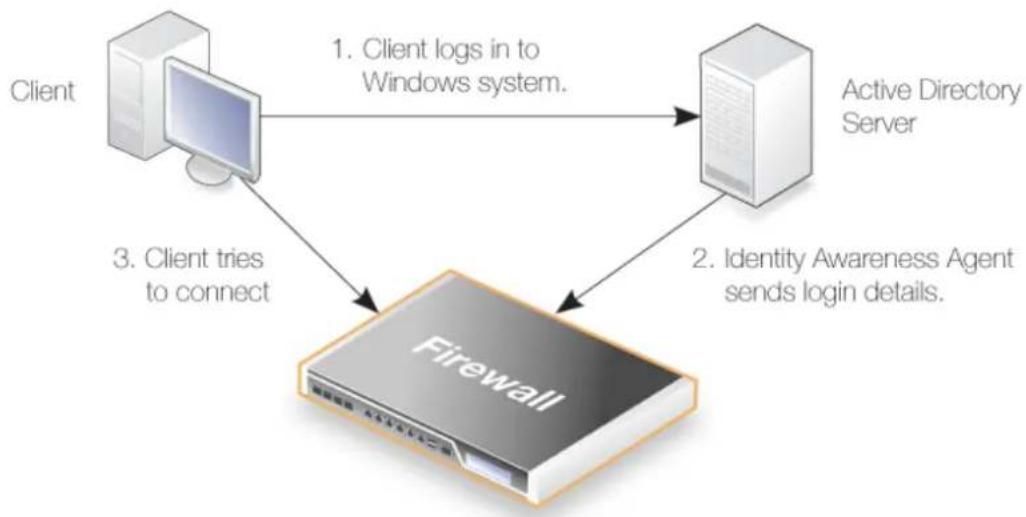
flowchart
graph TD
A["Client"] -->|1. Client logs in to Windows system.| B["Active Directory Server"]
A -->|3. Client tries to connect| C["Firewall"]
C -->|2. Identity Awareness Agent sends login details.| B
Figure 9.3. User Identity Awareness
Event Flow During Authentication
The flow of events with the identity awareness feature is as follows:
• A user of a Windows based client computer logs in.
• The user is authenticated against a Windows Active Directory server.
• The D-Link Identity Awareness Agent (IDA) is running on at least one server in the domain. This
software listens for successful client authentications. When a client is authenticated, the agent sends the following to the configured D-Link firewall:
i. The user name.
ii. The user's group.
iii. The user's IP.
- The user's IP address is now authenticated to NetDefendOS and connections coming from that IP are permitted through the firewall if an IP rule set entry is defined to allow it.
• A client attempts to open a connection through NetDefendOS.
• An IP rule set entry is triggered that could allow this connection. - The source network address object for the triggered entry has an associated authentication list of allowed usernames and groups. If the client is part of this list, the connection can be established.
The IP rule set entry that is created for authentication has the dual purpose of identifying and allowing the connection as well as triggering the authentication process. Address translation could also be applied.

Note: IDA is not aware of NetDefendOS authentication
The purpose of the IDA service is to send details of authentication events to NetDefendOS. This communication is one way and the IDA service is not aware of the authentications being carried out by NetDefendOS and does not display this information in its interface.
9.6.2. Setting Up Identity Awareness
To set up identity awareness, the following steps are required:
- Install and configure the Identity Awareness Agent (IDA) software on one or more domain servers. The servers can be either a domain controller or a domain member. Installation on a single server is sufficient but installation on multiple servers will provide redundancy.
Note that the details of both the installation and management of the IDA software are described in the separate Identity Awareness Administration Guide. The IDA software is not supplied with a NetDefendOS but is downloaded as a separate software package from the D-Link website. It has its own version numbering system and new versions with new features may be released at any time.
- Configure an Authentication Agent object in NetDefendOS which has IP Address and Pre-shared Key properties that correspond to the ones used by the agents installed on the domain servers. A separate Authentication Agent object should be created for each server in the domain which has the IDA software installed.
If the Pre-shared Key property is not specified, this defaults to the value of the predefined PSK object auth_agent_psk. This is also the default key value used by the D-Link Identity Awareness Agent. However, the default key is the same across all NetDefendOS systems and should be used for testing purposes only.
An IP rule rule set entry is not needed in NetDefendOS to allow the traffic coming from the agent.
- Configure an address book IP4 Address object that defines the IP address, IP range or network from which authenticating clients will come.
In the Authentication property of this address object, specify the usernames and/or groups which are allowed to create connections. Usernames must be specified in the format username@domain. For example, myusername@example.com. If this format with the @ symbol is not used and a simple string is used, for example myusername, then this will be treated as a group.

Important: Use underscore instead of space in group names
Group names must not contain spaces in NetDefendOS. The group name on the domain controller server can contain spaces but this must be replaced by the underscore character "_" when the group name is specified in NetDefendOS.
- Specify an entry in the NetDefendOS IP rule set that triggers on the client connections to be authenticated and allows them to be opened. The source network for this rule or policy must be the IPv4 address object specified in the previous step.
It is the triggering of the IP rule set entry that triggers the authentication process.
Example 9.7. Enabling User Identity Awareness
This example assumes that there are external clients on a network client_net connected to the If1 interface. These clients will want HTTP access to hosts on a network server_net on the If2 interface.
Clients connections will be authenticated using the identity awareness feature. The only usernames that will be allowed are user1@mydomain and user2@mydomain.
It is also assumed that the D-Link Authentication Agent software has already been installed on a single external Windows domain server and is configured with the IPv4 address defined by the address book object aa_server_ip and the pre-shared key defined by the aa_server_key PSK object.
It is assumed that the domain has only one server.
Command-Line Interface
Define an Authentication Agent object that describes the external server:
gw-world:/> add AuthAgent IPAddress=aa_server_ip
PSK=aa_server_key
Name=my_auth_agent
Assign the permitted usernames to the network object for client IPs:
gw-world:/> set Address IP4Address client_net
UserAuthGroups=user1@mydomain, user2@mydomain
Create an IP Policy which allows access and uses client_net as the source network.
gw-world:/> add IPPolicy Name=client_to_server
SourceInterface=If1
SourceNetwork=client_net
DestinationInterface=If2
DestinationNetwork=server_net
Service=http-all
Action=Allow
Web Interface
Define the Authentication Agent object that describes the external server:
- Go to:
Policies > Authentication > Authentication Agents > Add > Authentication Agent
-
Now enter:
-
Name: my_auth_agent
- IP Address: aa_server_ip
-
Pre-shared key: aa_server_key
-
Click OK
Assign the permitted usernames to the network object for client IPs:
- Go to: Objects > Address Book > client_net
- Select the User Authentication tab
- In the username box enter: user1@mydomain, user2@mydomain
- Click OK
Create an IP Policy which allows access to the servers by the clients and uses client_net as the source network.
-
Go to: Policies > Firewalling > Main IP Rules > Add > IP Policy
-
Now enter:
-
Name: client_to_server
• Action: Allow -
Under Filter enter:
-
Source Network: client_net
- Source Interface: If1
- Destination Network: server_net
-
Destination Interface: If2
• Service: http-all -
Click OK
Note that in this example, individual usernames are used in the address object to specify which users can be authenticated. As discussed earlier in this section, a group name could have been
used instead or in addition.
9.6.3. Monitoring Identity Awareness Activity
The administrator can ask NetDefendOS to show details of identity awareness activity.
In the Web Interface, the administrator can go to Status > Run-time Information > Authentication Agents to see that the IDA service is connected to NetDefendOS. In the CLI, the same can be achieved with the command:
gw-world:/> authagent
As users are authenticated, they can be seen in the Web Interface by going to Status > Run-time Information > User Authentication. In the CLI, the same can be achieved with the command:
gw-world:/> userauth -list
In order to switch on console monitoring of the communication taking place between NetDefendOS and the IDA service on the domain server, use the command:
gw-world:/> authagentsnoop <agent-name>
Entering the following command will terminate all snooping:
gw-world:/> authagentsnoop none
The options for all the above CLI commands are listed in the separate NetDefendOS CLI Reference Guide.
9.7. Multi Factor Authentication
When access to resources located behind a D-Link firewall is based on credentials, the security can be further strengthened by using Multi Factor Authentication. This is sometimes referred to as 2-factor authentication or 2-step authentication. One factor is usually a conventional username/password combination. The other factor is typically a multi-digit code which might be sent to the user at the time of the login via SMS or e-mail, or might be generated in some way by the user themselves (for example with a code-box or pre-generated code list). This code is sometimes referred to as a one-time password (OTP).
Multi Factor Support is Automatic
By default, NetDefendOS provides support for multi factor authentication by being able to recognize a RADIUS Access-Challenge message and displaying a special webpage to request the additional code. This webpage is predefined in NetDefendOS and has the Banner File name LoginChallenge.
Mobile VPN IPsec clients are also supported by multi-factor authentication when using the following authentication methods:
- IKEv1 with XAuth.
- IKEv2 with EAP.
Multi Factor Processing Sequence
The sequence of processing for multi factor authentication with NetDefendOS is as follows:
• Authentication is set up as normal using authentication rules and an IP rule set entries.
- The authentication source will be an external RADIUS server that has been configured to perform multi factor authentication.
- A user tries to access resources through the D-Link firewall. They are presented with a standard NetDefendOS login challenge page and they enter their credentials.
- NetDefendOS now sends these credentials to the RADIUS server for authentication in a RADIUS Access-Request message.
• In multi factor authentication, the RADIUS server will do two things:
i. It informs NetDefendOS that multi factor authentication must be used by sending back a RADIUS Access-Challenge message.
ii. Depending on the type of the additional challenge, the server might also cause a one-time code to be sent to the user. For example, this might be in an SMS message to a mobile device. Alternatively, the code might be generated by the user themselves using, for example, a code box.
The diagram below illustrates all the steps up to this point. In this diagram, it is assumed that the RADIUS server causes the code to be sent in an SMS message to the user's smartphone. Usually, a RADIUS server will send a message to another specialized server to generate SMS messages.
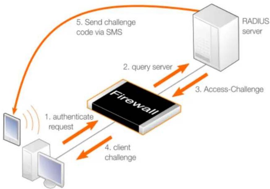
flowchart
graph TD
A["客户端"] -->|1. authenticate request| B["Firewall"]
B -->|2. query server| C["RADIUS server"]
C -->|3. Access-Challenge| B
B -->|4. client challenge| A
B -->|5. Send challenge code via SMS| C
Figure 9.4. Multi Factor Authentication
The process now completes with the following steps:
- The user enters the code they receive or generate themselves, and NetDefendOS relays the entered code to the RADIUS server in another Access-Request message.
- The RADIUS server verifies the code. If the user is authenticated then an Access-Accept is sent back to NetDefendOS and the client is given access to protected resources. If it is not verified, the server sends back an Access-Reject message and access is denied by NetDefendOS.
Notes on Multi Factor Authentication
Some points to note about setting up multi factor authentication with NetDefendOS are the following:
- The same NetDefendOS setup is used if the challenge code is generated by a local code generating device such as the RSA SecureID™ product or if a RADIUS server causes it to be sent to the user.
- No extra configuration is required in NetDefendOS. However, if the banner file LoginChallenge is used in the challenge process, it may need to be edited to display the appropriate text. This is discussed further in Section 9.3, "Customizing Authentication HTML".
- The administrator must configure the RADIUS server appropriately and the server's documentation should be consulted on how to do this.
- If the RADIUS server causes a code to be sent to the user, this is independent of NetDefendOS. Various third party solutions are available to generate this code.
9.8. Radius Relay
Overview
The NetDefendOS feature RADIUS Relay is designed for telecom scenarios, such as Mobile Data Offloading (MDO), where User Equipment (UE), such as a smartphone, switches from an operator's wireless network to communicating using WiFi via an Access Point (AP). The AP connects the UE to resources, such as the Internet, via a D-Link firewall with the firewall controlling this access.
To gain access to the resources behind the firewall, the UE must authenticate itself via the AP using a RADIUS server. A RADIUS authentication request is sent to NetDefendOS by the AP which relays it to a RADIUS server. The server's reply is relayed back to the AP and authenticated users are entered into the NetDefendOS user list so that they can then be granted access to resources based on NetDefendOS security policies.
Event Sequence During RADIUS Relay Authentication
The following sequence of events occurs with radius relay:
• The UE requests network access from an AP.
- The AP sends a RADIUS Access-Request to NetDefendOS. Providing the NetDefendOS radius relay feature has been set up, this request is forwarded to the configured RADIUS server.
- The RADIUS server either authenticates or does not authenticate the UE by sending a RADIUS Access-Accept or Access-Reject message back to NetDefendOS. The content of these messages is examined by NetDefendOS as they are relayed back to the AP.
- If it is authenticated by the RADIUS server, the UE issues a DHCP request and a DHCP IP lease from the configured NetDefendOS DHCP server is sent back to the UE.
The DHCP server must be configured so that leases are only be distributed to authenticated clients (the LeasesRequireAuth option is enabled).
- Successful authentication also means that NetDefendOS includes the UE's username in its list of logged in users (visible with the CLI userauth command and through the Web Interface) and this allows the UE access to resources determined by predefined NetDefendOS security policies.
Using Group Membership
NetDefendOS security policies can be based on group membership where the UE's membership in a group determines if access is allowed. If this is the case, the RADIUS server must be specially configured to send back the group name of the user during authentication. In addition, RADIUS servers communicating with NetDefendOS must have the Vendor ID set correctly. Doing this is described further at the end of this section.
It is also important that that IP rule or IP policy that allows access by the UE must use an IP address object for its Source Network which has its Authentication property (the UserAuthGroups property in the CLI) set to the same group name sent back by the RADIUS server. Doing this is described further in Section 9.4, "IP Policies Requiring Authentication".
If validation with group membership is not required then the No Defined Credentials property of the IP address object used for the Source Network should be enabled.
A symptom that the group name has not been specified for the Source Network address object is that the connection will be dropped after the Idle Timeout period of the RADIUS Relay object has
elapsed, even through traffic has been flowing during that time.

Important: Enable the DHCP server LeasesRequireAuth option
If RADIUS relay is being used in a NetDefendOS configuration, all DHCP servers must be configured to only distribute leases to configured clients. This is done by enabling the LeasesRequireAuth property in the CLI and in the Web Interface, enabling the option Distribute leases only to RADIUS relay authenticated clients.
If this is not done on all DHCP servers, irrespective of whether they are used with RADIUS relay or not, it could possibly create a security vulnerability and allow an unauthenticated client access to protected resources.
Radius Relay Object Properties
The important properties of a Radius Relay object are as follows:
- Name
A descriptive name for the object which will be used throughout the configuration.
- DHCP Server
The DHCP server that will be used to hand out IP address leases once the UE is authenticated.
- Source Interface
This is the NetDefendOS interface on which NetDefendOS will listen for AP requests. This can be any of the following:
i. An Ethernet interface.
ii. A VLAN interface.
iii. An Interface Group.
If the property Override User Data Interface is set, this interface will only listen for the initial connection from the AP and carry authentication traffic. The interface assigned to Override User Data Interface will carry the data traffic. This explained further below.
- Client IP Filter
This specifies the source IP range that the AP belongs to. This will typically be a network range and it is recommended it is specified as a NetDefendOS address book object.
- Listening IP
This is the IP address that the AP will connect to on the Source Interface. If the listening interface is an Ethernet interface or VLAN it is optional and will default to the IP address of the interface if not specified.
If the Source Interface is an interface group, the listening IP must be specified.
- Listening Port
This is the listening port number for the listening interface and is 1812 by default.
• Override User Data Interface
By default, a user is authenticated using the same interface that is used for forwarding data
traffic and that is the value set for the Source Interface property above. This can pose a security risk and it is recommended to use different interfaces for these two functions. The Override User Data Interface property is set to the interface used only for data. Usually Source Interface and Override User Data Interface will be two different VLANs running over the physical interface connected to the AP. This is discussed further below.
- Routing Table
When the UE is authenticated and it receives an IP address, a route to its IP will be automatically added to this routing table. Usually, the default main routing table is used.
- Remote Server IP
This is the IP address of the RADIUS server that will perform UE authentication.
- Remote Server Port
This is the port number of the RADIUS server that will perform UE authentication. The default value is 1812 which is the standard for RADIUS.
- Sending IP
This optional IP address will be used as the sending IP of the request sent to the RADIUS server. If not set, the IP address of the sending interface will be used. The sending interface is determined by a route lookup of the RADIUS server's IP address.
- Idle Timeout
After this amount of seconds without traffic from the authenticated user, the user will be automatically logged out.
- Session Timeout
This is the absolute allowed length of a authenticated used session in seconds. This is normally set to zero, meaning a session of infinite length.
• Use Timeouts Received from Authentication Server
If this property is enabled and the RADIUS server is correctly configured, the Idle Timeout and Session Timeout properties will take values sent by the RADIUS server.
Separate Authentication and Data Traffic
It is strongly recommended to set the property Override User Data Interface to the interface used only for the data traffic so that it is different from the interface assigned to the Source Interface property for the authentication traffic. Typically, they will be set to two different VLAN interfaces which will run over the same physical Ethernet interface and which is connected to the AP. This will fully separate the authentication data going to the RADIUS server from the data flowing to the backbone network. Not doing this will pose a security risk.
The following should be noted when using the Override User Data Interface property:
- The administrator must ensure the AP sends authentication and data traffic are sent over the correct VLANs.
- The interface used for the DHCP server object which hands out IP addresses will be the interface used for the data (the Override User Data Interface) and not the interface used for authentication (the Source Interface).
- No extra IP rule set entry is required for either DNS traffic or authentication traffic. The IP rule set entry that allows data to flow from the client to the backbone is the only one required.
Example 9.8. Configuring Radius Relay
This example shows how to configure a Radius Relay object for the scenario illustrated below. Here, client devices (UE) must access data services through a backbone network via an Access Point (AP). First, they must be authenticated against a RADIUS server and then allocated an IP address. The AP is connected to the physical If1 Ethernet interface of a D-Link firewall and the backbone network is connected to the If2 interface.
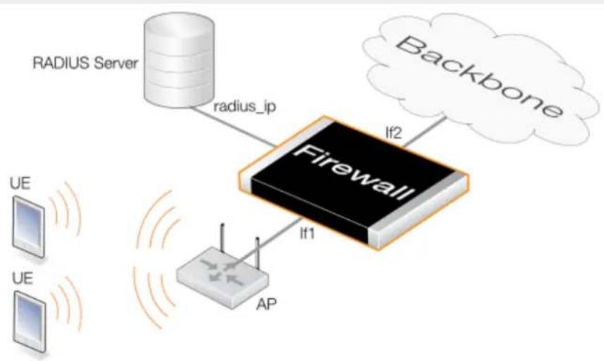
flowchart
graph TD
A["RADIUS Server"] -->|radius_ip| B["Firewall"]
C["Backbone"] -->|If2| B
D["UE"] -->|If1| E["AP"]
F["UE"] -->|Signal| E
The following assumptions are made:
- Two VLANs are already configured and these NetDefendOS objects are called vlan_auth for client authentication traffic and vlan_data for data traffic flowing to the backbone.
- Both these VLANs are already set up to run over the physical Ethernet interface If1 and that the AP has also been correctly configured to use the appropriate VLAN for authentication and data.
- Authenticated users must belong to the group called ue_group.
- A Radius Relay object called r_relay1 will be created which will listen for authentication requests on the vlan_auth interface and relay them to a RADIUS server with the IPv4 address radius_ip. The scenario is illustrated in the diagram below.
- After successful authentication, IP address leases will be handed out by a DHCP server object called rr_dhcp_server. It is assumed the UEs will be allocated addresses belonging to the network 192.168.10.10-192.168.10.255 that will be defined in an IPv4 address object called client_net.
- After successful authentication, UEs will be granted access to a backbone network on the If2 interface using an IP policy called client_access_rule.
Command-Line Interface
A. Create the IP4Address object that defines the range of client IP addresses for the UEs and assign it the authentication group called ue_group:
gw-world:/> add Address IP4Address client_net
Address=192.168.10.10-192.168.10.255
UserAuthGroups=ue_group
B. Create the IP4Address object that defines the IP address pool for the DHCP server. This must be a different object although it uses the same IP range:
gw-world:/> add Address IP4Address client_ip_range
Address=192.168.10.10-192.168.10.255
C. Create the DHCPServer object that hands out these addresses:
gw-world:/> add DHCPServer rr_dhcp_server
Interface=vlan_data
IPAddressPool=client_ip_range
Netmask=255.255.255.0
LeasesRequireAuth=Yes
D. Create the IPPolicy object that grants access for client data flowing to the backbone network which is connected to the interface If2:
gw-world:/> add IPPolicy Name=client_access_rule
SourceInterface=vlan_data
SourceNetwork=client_net
DestinationInterface=If2
DestinationNetwork=all-nets
Service=all_services
Action=Allow
E. Create the RadiusRelay object:
gw-world:/> add RadiusRelay r_relay1
SourceInterface=vlan_auth
ClientIPFilter=client_ip_range
RemoteServerIP=radius_ip
DHCPServer=rr_dhcp_server
OverrideUserDataInterface=vlan_data
Web Interface
A. Create the IP4Address object that defines the range of client IP addresses for the UEs and assign it the authentication group called ue_group:
-
Go to: Objects > Address Book > Add > IP4 Address
-
Now enter:
-
Name: client_net
• IP Address: 192.168.10.0/24 -
User Authentication: ue_group
-
Click OK
B. Create the IP4Address object that defines the IP address pool for the DHCP server. This must be a different object although it uses almost the same IP range:
-
Go to: Objects > Address Book > Add > IP4 Address
-
Now enter:
-
Name: client_ip_range
• IP Address: 192.168.10.10-192.168.10.255 -
Click OK
C. Create the DHCPServer object that hands out these addresses:
-
Go to: Network > Network Services > DHCP Servers > Add > DHCPServer
-
Now enter:
-
Name: rr_dhcp_server
-
Interface: vlan_data
• Interface Filter: client_ip_range
• Netmask: 255.255.255.0 -
Select the Options tab and enable the option: Distribute leases only to RADIUS relay authenticated clients
-
Click OK
D. Create the IP Policy object that grants access for client data flowing to the backbone network which is connected to the interface If2:
-
Go to: Policies > Firewalling > Main IP Rules > Add > IP Policy
-
Now enter:
-
Name: client_access_rule
-
Action: Allow
-
Under Filter enter:
-
Source Interface: vlan_data
- Source Network: client_net
- Destination Interface: If2
-
Destination Network: all-nets
• Service: all_services -
Click OK
E. Create the RadiusRelay object:
- Go to: Network > Network Services > RADIUS Relays > add > RADIUS Relay
-
Now enter:
-
Name: r_relay1
- DHCP Server: rr_dhcp_server
- Source Interface: vlan_auth
- Client IP Filter: client_ip_range
• Remote Server IP: radius_ip
• Override User Data Interface: vlan_data
3. Click OK

Note: Configuring the RADIUS server to send the group name
In the above example, it is assumed the group name ue_group will be sent back by the RADIUS server during authentication. The RADIUS server must be configured to do this.
When configuring the external RADIUS server to provide group information for the logged in user to NetDefendOS, it is necessary to use the user group vendor specific attribute. The NetDefendOS Vendor ID is 5089 and the user group is defined as vendor-type 1 with a string value type.
9.9. RADIUS Accounting
9.9.1. Overview
The Central Database Approach
Within a network environment containing large numbers of users, it is advantageous to have one or a cluster of central servers that maintain user account information and are responsible for authentication and authorization tasks. The central database residing on such dedicated servers contains all user credentials as well as details of connections. This significantly reducing administration complexity.
The Remote Authentication Dial-in User Service (RADIUS) is an Authentication, Authorization and Accounting (AAA) protocol widely used to implement this central database approach and is used by NetDefendOS to implement user accounting.
RADIUS Architecture
The RADIUS protocol is based on a client/server architecture. The D-Link firewall acts as the client of the RADIUS server, creating and sending requests to a dedicated server(s). In RADIUS terminology the firewall acts as the Network Access Server (NAS).
For user authentication, the RADIUS server receives the requests, verifies the user's information by consulting its database, and returns either an "accept" or "reject" reply to the requesting client.
With the RFC 2866 standard, RADIUS was extended to handle the delivery of accounting information and this is the standard followed by NetDefendOS for user accounting. In this way, all the benefits of centralized servers are thus extended to user connection accounting.
The usage of RADIUS for NetDefendOS authentication is discussed in Section 9.2, "Authentication Setup".
9.9.2. RADIUS Accounting Messages
Message Generation
Statistics, such as number of bytes sent and received, and number of packets sent and received are updated and stored throughout RADIUS sessions. All statistics are updated for an authenticated user whenever a connection related to an authenticated user is closed.
When a new client session is started by a user establishing a new connection through the firewall, NetDefendOS sends an AccountingRequest START message to a nominated RADIUS server, to record the start of the new session. User account information is also delivered to the RADIUS server. The server will send back an AccountingResponse message to NetDefendOS, acknowledging that the message has been received.
When a user is no longer authenticated, for example, after the user logs out or the session time expires, an AccountingRequest STOP message is sent by NetDefendOS containing the relevant session statistics. The information included in these statistics is user configurable. The contents of the START and STOP messages are described in detail below:
START Message Parameters
Parameters included in START messages sent by NetDefendOS are:
- Type - Marks this AccountingRequest as signaling the beginning of the service (START).
- ID - A unique random 7 character string identifier to enable matching of an AccountingRequest with Acct-Status-Type set to STOP.
- User Name - The user name of the authenticated user.
• NAS IP Address - The IP address of the D-Link firewall.
- NAS Port - The port of the NAS on which the user was authenticated (this is a physical interface and not a TCP or UDP port).
- User IP Address - The IP address of the authenticated user. This is sent only if specified on the authentication server.
- How Authenticated - How the user was authenticated. This is set to either RADIUS if the user was authenticated via RADIUS, or LOCAL if the user was authenticated via a local user database.
- Delay Time - The time delay (in seconds) since the AccountingRequest packet was sent and the authentication acknowledgment was received. This can be subtracted from the time of arrival on the server to find the approximate time of the event generating this AccountingRequest. Note that this does not reflect network delays. The first attempt will have this parameter set to 0.
- Timestamp - The number of seconds since 1st January, 1970. Used to set a timestamp when this packet was sent from NetDefendOS.
STOP Message Parameters
Parameters included in STOP messages sent by NetDefendOS are:
- Type - Marks this accounting request as signaling the end of a session (STOP).
- ID - An identifier matching a previously sent AccountingRequest packet, with Acct-Status-Type set to START.
- User Name - The user name of the authenticated user.
• NAS IP Address - The IP address of the D-Link firewall.
- NAS Port - The port on the NAS on which the user was authenticated. (This is a physical interface and not a TCP or UDP port).
- User IP Address - The IP address of the authenticated user. This is sent only if specified on the authentication server.
- Input Bytes - The number of bytes received by the user. (*)
• Output Bytes - The number of bytes sent by the user. (*)
- Input Packets - The number of packets received by the user. (*)
• Output Packets - The number of packets sent by the user. (*)
- Session Time - The number of seconds this session lasted. (*)
• Termination Cause - The reason why the session was terminated.
- How Authenticated - How the user was authenticated. This is set to either RADIUS if the user was authenticated via RADIUS, or LOCAL if the user was authenticated via a local user database.
- Delay Time - See the above comment about this parameter.
- Timestamp - The number of seconds since 1970-01-01. Used to set a timestamp when this packet was sent from the firewall.
In addition, two more attributes may be sent:
- Input Gigawords - Indicates how many times the Input Bytes counter has wrapped. This is only sent if Input Bytes has wrapped, and if the Input Bytes attribute is sent.
- Output Gigawords - Indicates how many times the Output Bytes counter has wrapped. This is only sent if Output Bytes has wrapped, and if the Output Bytes attribute is sent.

Tip: The meaning of the asterisk after a list entry
The asterisk (*) symbol after an entry in the list above indicates that the sending of the parameter is optional and is configurable.
9.9.3. Interim Accounting Messages
In addition to START and STOP messages NetDefendOS can optionally periodically send Interim Accounting Messages to update the accounting server with the current status of an authenticated user.
Messages are Snapshots
An interim accounting message can be seen as a snapshot of the network resources that an authenticated user has used up until a given point. With this feature, the RADIUS server can track how many bytes and packets an authenticated user has sent and received up until the point when the last message was sent.
An Interim Accounting Message contains the current values of the statistics for an authenticated user. It contains more or less the same parameters as found in an accounting request STOP message, except that the Acct-Terminate-Cause is not included (as the user has not disconnected yet).
Message Frequency
The frequency of interim accounting messages can be specified either on the authentication server or in NetDefendOS. Switching on the setting in NetDefendOS will override the setting on the accounting server.
9.9.4. Configuring RADIUS Accounting
In order to activate RADIUS accounting a number of steps must be followed:
• The RADIUS server must be defined in NetDefendOS.
- A user authentication object must have a rule associated with it where a RADIUS server is specified.
• The external RADIUS server itself must be correctly configured.
Setting the Source IP
By default, the Source IP property will be set to Automatic and the IP address of the firewall's sending interface will be used as the source address for traffic sent to the RADIUS server. If this property is set to Manual, a specific source IP address can be used for traffic sent to the server.
If the source IP address is specified, the administrator must also manually configure NetDefendOS to ARP publish the IP address on the sending interface. Doing this is described in Section 3.5.3, "ARP Publish".
Further RADIUS Considerations
Some important points should be noted about RADIUS activation:
- RADIUS accounting will not function where a connection is subject to a Stateless Policy entry in the IP rule set (or a FwdFast IP rule).
- The same RADIUS server does not need to handle both authentication and accounting; one server can be responsible for authentication while another is responsible for accounting tasks.
- Multiple RADIUS servers can be configured in NetDefendOS to deal with the event when the primary server is unreachable.
Example 9.9. RADIUS Accounting Server Setup
This example shows configuring of NetDefendOS with a local RADIUS server called my-accounting using IP address 192.168.3.1 and port 1813. Assume the shared secret is 231562514098273.
Command-Line Interface
gw-world:/> add RadiusAccounting my-accounting
IPAddress=192.168.3.1
SharedSecret=231562514098273
Port=1813
RetryTimeout=2
RoutingTable=main
Web Interface
-
Go to: Policies > User Authentication > Accounting > RADIUS > Add > RADIUS Server
-
Now enter:
-
Name: my-accounting
• IP Address: 192.168.3.1
• Port: 1813 - Retry Timeout: 2
• Shared Secret: 231562514098273
• Confirm Secret: 231562514098273
- Routing Table: main
- Click OK
9.9.5. RADIUS Accounting Security
Communication between NetDefendOS and any RADIUS accounting server is protected by the use of a shared secret. This secret is never sent over the network but instead a 16 byte long Authenticator code is calculated using a one way MD5 hash function and this is used to authenticate accounting messages.
The shared secret is case sensitive, can contain up to 128 characters, and must be typed exactly the same for NetDefendOS and for the RADIUS server.
Messages are sent using the UDP protocol and the default port number used is 1813 although this is user configurable.
9.9.6. RADIUS Accounting and High Availability
In an HA cluster, accounting information is synchronized between the active and passive firewalls. This means that accounting information is automatically updated on both cluster members whenever a connection is closed.
Special Accounting Events
Two special accounting events are also used by the active unit to keep the passive unit synchronized:
- An AccountingStart event is sent to the inactive member in an HA setup whenever a response has been received from the accounting server. This specifies that accounting information should be stored for a specific authenticated user.
- A problem with accounting information synchronization could occur if an active unit has an authenticated user for whom the associated connection times out before it is synchronized on the inactive unit.
To get around this problem, a special AccountingUpdate event is sent to the passive unit on a timeout and this contains the most recent accounting information for connections.
9.9.7. Handling Unresponsive RADIUS Servers
It can happen that a RADIUS client sends an AccountingRequest START packet which a RADIUS server never replies to. If this happens, NetDefendOS will re-send the request after the user-specified number of seconds. This will mean, however, that a user will still have authenticated access while NetDefendOS is trying to contact to the accounting server.
Three Connection Attempts are Made
Only after NetDefendOS has made three attempts to reach the server will it conclude that the accounting server is unreachable. The administrator can use the NetDefendOS advanced setting Allow on error to determine how this situation is handled.
If the Allow on error setting is enabled, an already authenticated user's session will be unaffected. If it is not enabled, any affected user will automatically be logged out even if they have already been authenticated.
9.9.8. Accounting and System Shutdowns
In the case that the client for some reason fails to send a RADIUS AccountingRequest STOP packet, the accounting server will never be able to update its user statistics, but will most likely believe that the session is still active. This situation should be avoided.
In the case that the firewall administrator issues a shutdown command while authenticated users are still online, the AccountingRequest STOP packet will potentially never be sent. To avoid this, the advanced setting Logout at shutdown allows the administrator to explicitly specify that NetDefendOS must first send a STOP message for any authenticated users to any configured RADIUS servers before commencing with the shutdown.
9.9.9. Limitations with NAT
The User Authentication module in NetDefendOS is based on the user's IP address. Problems can therefore occur with users who have the same IP address.
This can happen, for example, when several users are behind the same network using NAT to allow network access through a single external IP address. This means that as soon as one user is authenticated, traffic coming through that NAT IP address could be assumed to be coming from that one authenticated user even though it may come from other users on the same network. NetDefendOS RADIUS Accounting will therefore gather statistics for all the users on the network together as though they were one user instead of individuals.
9.9.10. Advanced RADIUS Settings
The following advanced settings are available with RADIUS accounting:
Allow on error
If there is no response from a configured RADIUS accounting server when sending accounting data for a user that has already been authenticated, then enabling this setting means that the user will continue to be logged in.
Disabling the setting will mean that the user will be logged out if the RADIUS accounting server cannot be reached even though the user has been previously authenticated.
Default: Enabled
Logout at shutdown
If there is an orderly shutdown of the firewall by the administrator, NetDefendOS will delay the shutdown until it has sent RADIUS accounting STOP messages to any configured RADIUS server.
If this option is not enabled, NetDefendOS will shut down even though there may be RADIUS accounting sessions that have not been correctly terminated. This could lead to the situation that the RADIUS server will assume users are still logged in even though their sessions have been terminated.
Default: Enabled
Maximum Radius Contexts
The maximum number of contexts allowed with RADIUS. This applies to RADIUS use with both accounting and authentication.
Default: 1024
Chapter 10: VPN
This chapter describes the Virtual Private Network (VPN) functionality in NetDefendOS.
• Overview, page 768
• VPN Quick Start, page 772
• IPsec, page 784
• PPTP/L2TP, page 862
• L2TP Version 3, page 874
- SSL VPN, page 886
10.1. Overview
10.1.1. VPN Usage
The Internet is increasingly used as a means to connect together computers since it offers efficient and inexpensive communication. The requirement therefore exists for data to traverse the Internet to its intended recipient without another party being able to read or alter it.
It is equally important that the recipient can verify that no one is falsifying data, in other words, pretending to be someone else. Virtual Private Networks (VPNs) meet this need, providing a highly cost effective means of establishing secure links between two co-operating computers so that data can be exchanged in a secure manner.
VPN allows the setting up of a tunnel between two devices known as tunnel endpoints. All data flowing through the tunnel is then secure. The mechanism that provides tunnel security is encryption.
There are two common scenarios where VPN is used:
- LAN-to-LAN connection - Where two internal networks need to be connected together over the Internet. In this case, each network is protected by an individual D-Link firewall and the VPN tunnel is set up between them.
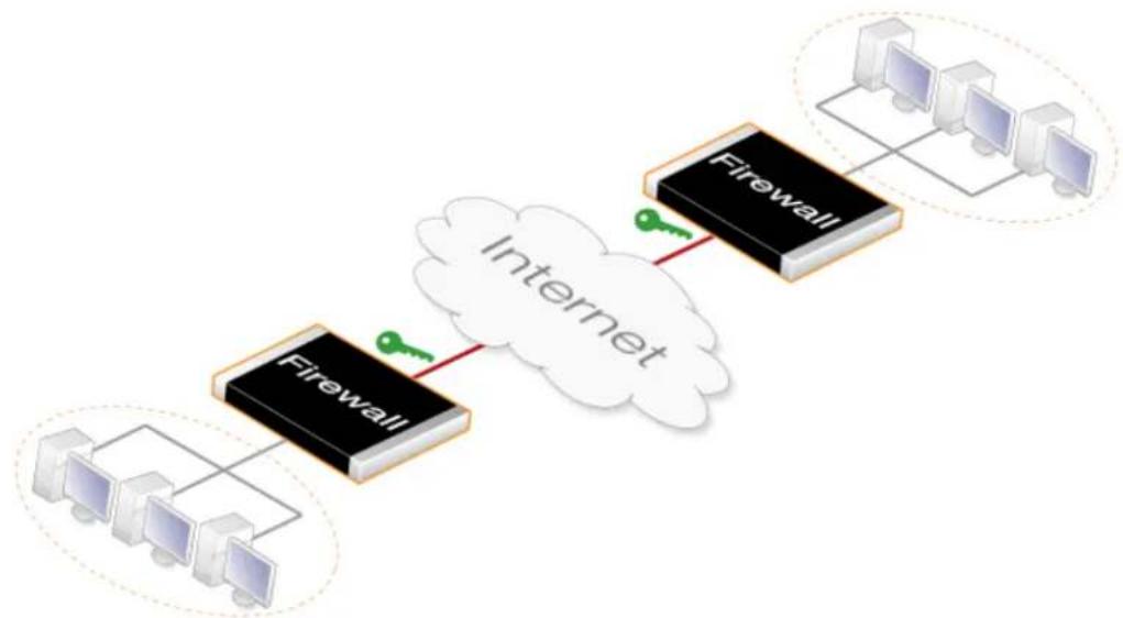
flowchart
graph TD
A["Firewall"] --> B["Internet"]
C["Computer 1"] --> D["Firewall"]
E["Computer 2"] --> F["Firewall"]
G["Computer 3"] --> H["Firewall"]
I["Computer 4"] --> J["Firewall"]
style A fill:#000,stroke:#fff,color:#fff
style B fill:#000,stroke:#fff,color:#fff
style C fill:#000,stroke:#fff,color:#fff
style D fill:#000,stroke:#fff,color:#fff
style E fill:#000,stroke:#fff,color:#fff
style F fill:#000,stroke:#fff,color:#fff
style G fill:#000,stroke:#fff,color:#fff
style H fill:#000,stroke:#fff,color:#fff
style I fill:#000,stroke:#fff,color:#fff
style J fill:#000,stroke:#fff,color:#fff
- Client to LAN connection - Where many remote clients need to connect to an internal network over the Internet. In this case, the internal network is protected by the firewall to which the client connects and the VPN tunnel is set up between them.
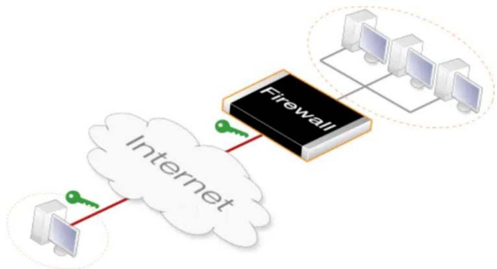
flowchart
graph TD
A["Computer"] -->|Red Key Point| B["Cloud"]
C["Internet"] -->|Green Key Point| D["Firewall"]
D --> E["Computer 1"]
D --> F["Computer 2"]
D --> G["Computer 3"]
D --> H["Computer 4"]
10.1.2. VPN Encryption
Encryption of VPN traffic is done using the science of cryptography. Cryptography is an umbrella expression covering 3 techniques and benefits:
Confidentiality No one but the intended recipients is able to receive and understand the communication. Confidentiality is accomplished by encryption.
Authentication and Integrity
Proof for the recipient that the communication was actually sent by the expected sender, and that the data has not been modified in transit. This is accomplished by authentication, and is often implemented through the use of cryptographic keyed hashing.
Non-repudiation Proof that the sender actually sent the data; the sender
cannot later deny having sent it. Non-repudiation is usually a side-effect of authentication.
VPNs are normally only concerned with confidentiality and authentication. Non-repudiation is normally not handled at the network level but rather is usually done at a higher, transaction level.
10.1.3. VPN Planning
An attacker targeting a VPN connection will typically not attempt to crack the VPN encryption since this requires enormous effort. They will, instead, see VPN traffic as an indication that there is something worth targeting at the other end of the connection. Typically, mobile clients and branch offices are far more attractive targets than the main corporate network. Once inside those, getting to the corporate network then becomes easier.
In designing a VPN there are many issues that need to be addressed which aren't always obvious. These include:
• Protecting mobile and home computers.
- Restricting access through the VPN to needed services only, since mobile computers are vulnerable.
- Creating DMZs for services that need to be shared with other companies through VPNs.
• Adapting VPN access policies for different groups of users.
- Creating key distribution policies.
Endpoint Security
A common misconception is that VPN-connections are equivalents to the internal network from a security standpoint and that they can be connected directly to it with no further precautions. It is important to remember that although the VPN-connection itself may be secure, the total level of security is only as high as the security of the tunnel endpoints.
It is becoming increasingly common for users on the move to connect directly to their company's network via VPN from their laptops or tablets. However, the client equipment itself is often not protected. In other words, an intruder can gain access to the protected network through an unprotected laptop and already-opened VPN connections.
Placement in a DMZ
A VPN connection should never be regarded as an integral part of a protected network. The VPN firewall should instead be located in a special DMZ or outside a firewall dedicated to this task. By doing this, the administrator can restrict which services can be accessed via the VPN and ensure that these services are well protected against intruders.
In instances where the firewall features an integrated VPN feature, it is usually possible to dictate the types of communication permitted and NetDefendOS VPN has this feature.
10.1.4. Key Distribution
Key distribution schemes are best planned in advance. Issues that need to be addressed include:
- How will keys be distributed? Email is not a good solution. Phone conversations might be secure enough.
- How many different keys should be used? One key per user? One per group of users? One per LAN-to-LAN connection? One key for all users and one key for all LAN-to-LAN connections? It is probably better using more keys than is necessary today since it will be easier to adjust access per user (group) in the future.
- Should the keys be changed? If they are changed, how often? In cases where keys are shared by multiple users, consider using overlapping schemes, so that the old keys work for a short period of time when new keys have been issued.
- What happens when an employee in possession of a key leaves the company? If several users are using the same key, it should be changed.
- In cases where the key is not directly programmed into a network unit, such as a VPN firewall, how should the key be stored? On a floppy? As a pass phrase to memorize? On a smart card? If it is a physical token, how should it be handled?
10.1.5. The TLS Alternative for VPN
If secure access by clients to web servers using HTTP is the scenario under consideration, then using a D-Link firewall for TLS termination can offer an alternative "lightweight" VPN approach that is quickly and easily implemented. This topic is described further in Section 6.1.11, "TLS ALG".
10.2. VPN Quick Start
Overview
Later sections in this chapter will explore VPN components in detail. To help put those later sections in context, this section is a quick start summary of the steps needed for VPN setup. In most cases, the setup steps with IKEv1 and IKEv2 are similar and any differences are pointed out. IKEv2 is usually the preferred choice because it is considered more robust and is the normal choice for roaming clients since most in-built IPsec clients are IKEv2 based. However, IKEv2 cannot be used with L2TP.
The section outlines the individual steps required for setting up VPNs for the most common scenarios. The included subsections are the following:
• Section 10.2.1, "IPsec LAN-to-LAN with Pre-shared Keys".
• Section 10.2.2, "IPsec LAN-to-LAN with Certificates".
• Section 10.2.3, "IPsec Roaming Clients with Pre-shared Keys".
• Section 10.2.4, "IPsec Roaming Clients with Certificates".
• Section 10.2.5, "L2TP/IPsec Roaming Clients with Pre-Shared Keys".
• Section 10.2.6, "L2TP/IPsec Roaming Clients with Certificates".
• Section 10.2.7, "PPTP Roaming Clients".

Tip: IPsec profiles can simplify IPsec tunnel setup
The IPsec setup steps described below are based on the standard IPsec Tunnel object. NetDefendOS also provides the LAN to LAN VPN and Roaming VPN objects which simplify setup for NetDefendOS to NetDefendOS LAN-to_LAN and roaming clients respectively.
These IPsec profile objects hide those IPsec Tunnel object properties that are not relevant to these scenarios and can also simplify authentication setup. Both are IKEv2 based and are discussed further in Section 10.3.15, "Using IPsec Profiles".
Common Tunnel Setup Requirements
Before looking at each of these scenarios separately, it is useful to summarize the common NetDefendOS requirements when setting up any VPN tunnel, regardless of the type.
- Define the Tunnel
Firstly we must define the tunnel itself. NetDefendOS has various tunnel object types which are used to do this, such as an IPsec Tunnel object.
• A Route Must Exist
Before any traffic can flow into the tunnel, a route must be defined in a NetDefendOS routing table. This route tells NetDefendOS which network can be found at the other end of the tunnel so it knows which traffic to send into the tunnel.
In most cases, this route is created automatically when the tunnel is defined and this can be checked by examining the routing tables.
If a route is defined manually, the tunnel is treated exactly like a physical interface in the route properties, as it is in other aspects of NetDefendOS. In other words, the route is saying to NetDefendOS that a certain network is found at the other end of the tunnel.
• Define an IP Policy to Allow VPN Traffic
An IP policy must be defined that explicitly allows traffic to flow between a network and the tunnel. As with route definitions, the tunnel is treated exactly like a physical interface when defining the IP policy.
Note that the required IP policy will not be created automatically after defining the tunnel object and if it does not exist then no traffic can flow through the tunnel and will be dropped instead
The following sections will look at the detailed setup for each of the VPN scenarios listed earlier.
10.2.1. IPsec LAN-to-LAN with Pre-shared Keys
The objective is to create a secure means of joining the following two networks:
• A Local Network which is on the protected side of a local firewall.
- A Remote Network which is on the other side of some remote device and which is located across an insecure network such as the Internet.
The steps for setup are as follows:
-
Create a Pre-shared Key object.
-
Optionally create a new IKE Algorithms object and/or an IPsec Algorithms object if the default algorithm proposal lists do not provide a set of algorithms that are acceptable to the tunnel remote endpoint. This will depend on the capabilities of the device at the other end of the VPN tunnel.
-
In the Address Book create IP objects for:
-
The remote VPN gateway which is the IPv4 address of the network device at the other end of the tunnel (let's call this object remote_gw). This may or may not be another D-Link firewall.
- The remote network which lies behind the remote VPN gateway (let's call this object remote_net).
- The local network behind the firewall which will communicate across the tunnel. Here we will assume that this is the predefined address lannet and this network is attached to the NetDefendOS lan interface which has the IPv4 address lan_ip .
The diagram below illustrates this setup.
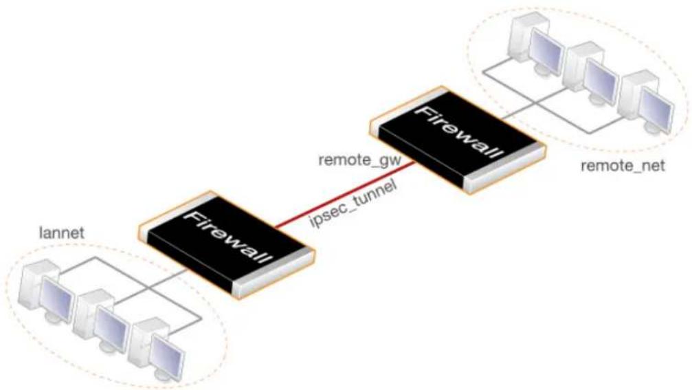
flowchart
graph LR
A["Iannet"] --> B["Firewall"]
B -->|ipsec_tunnel| C["Firewall"]
C --> D["remote_net"]
style A fill:#f9f,stroke:#333
style B fill:#ccf,stroke:#333
style C fill:#cfc,stroke:#333
style D fill:#fcc,stroke:#333
-
Create an IPsec Tunnel object (let's call this object ipsec_tunnel). Specify the following tunnel parameters:
-
Select the IKE version. The Auto option is recommended to try IKEv2 first.
• Set Local Network to lannet. - Set Remote Network to remote_net.
- Set Remote Endpoint to remote_gw.
- For IKEv1, set Encapsulation mode to Tunnel. IKEv2 always uses Tunnel and it does not need to be set.
- Choose the IKE and IPsec algorithm proposal lists to be used.
• For Authentication select the Pre-shared Key object defined in step (1) above. - Note that the IPsec tunnel property Add route statically is enabled by default and this will automatically add a route to the Remote Network to the main routing table in the NetDefendOS configuration. No route needs to be added manually.
The IPsec Tunnel object can be treated exactly like any NetDefendOS Interface object in later steps.
-
Create the following two IP policies for the tunnel in the IP rule set:
-
An Allow IP policy for outbound traffic that has the previously defined ipsec_tunnel object as the Destination Interface. The policy's Destination Network is the remote network remote_net.
- An Allow IP policy for inbound traffic that has the previously defined ipsec_tunnel object as the Source Interface. The Source Network is remote_net.
| Action | Src Interface | Src Network | Dest Interface | Dest Network | Service |
| Allow | lan | lannet | ipsec_tunnel | remote_net | all_services |
| Allow | ipsec_tunnel | remote_net | lan | lannet | all_services |
The Service object used in these IP policies is all_services which allows all protocols. However, a
narrower service could be used. For example, the service http-all would allow only HTTP and HTTPS traffic.
- Define a new NetDefendOS Route which specifies that the VPN Tunnel ipsec_tunnel is the Interface to use for routing packets bound for the remote network at the other end of the tunnel.
| Interface Network Gateway | ||
| ipsec_tunnel remote_net |
For a LAN-to-LAN example showing the actual configuration steps, go to Example 10.3, "PSK Based LAN-to-LAN IPsec Tunnel Setup".
10.2.2. IPsec LAN-to-LAN with Certificates
LAN-to-LAN security is usually provided with pre-shared keys but sometimes it may be desirable to use X.509 certificates instead. If this is the case, Certificate Authority (CA) signed certificates may be used and these come from an internal CA server or from a commercial supplier of certificates.
Creating a LAN-to-LAN tunnel with certificates follows exactly the same procedures as the previous section where a pre-shared key was used. The difference is that certificates now replace pre-shared keys for authentication.
Two unique sets of two CA signed certificates (two for either end, a root certificate and a gateway certificate) are required for a LAN-to-LAN tunnel authentication.
The setup steps are as follows:
-
Open the management Web Interface for the D-Link firewall at one end of the tunnel.
-
Under Key Ring, upload the Root Certificate and Gateway Certificate into NetDefendOS. The root certificate needs just a single certificate file for the public key. The gateway certificate needs to 2 parts: a certificate file for the public key as well as a private key file. Any intermediate certificates required for a certificate chain between the root and gateway certificate should also have the certificate files for their public key uploaded.
Note that the Gateway Certificate is sometimes referred to as the Host Certificate.
-
Set up the IPsec Tunnel object as for pre-shared keys, but specify the certificates to use under Authentication. Do this with the following steps:
-
Enable the X.509 Certificate option.
-
Select the Root Certificate to use. If there is a certificate chain to the gateway certificate, all the intermediate certificates must also be added as root certificates.
• Select the Gateway Certificate. -
Open the management Web Interface for the D-Link firewall at the other side of the tunnel and repeat the above steps with a different set of certificates.
Also review Section 3.9.4, "CA Server Access" below, which describes important considerations for certificate validation.
Self-signed certificates instead of CA signed certificates can be used for LAN-to-LAN tunnels but the standard NetDefendOS user interfaces do not have a feature to generate them. They can be
generated by another utility and imported into NetDefendOS. This means that they are not truly self-signed since they are generated outside of NetDefendOS control and it should be remembered that there is no guarantee that their private key is unique. However, the security provided can still be considered adequate for some scenarios.
Two self-signed certificates are required for an IPsec tunnel and the same two are used at either end of the tunnel but their usage is reversed. In other words: one certificate is used as the root certificate at one end, call it Side A, and as the host certificate at the other end, call it Side B. The second certificate is used in the opposite way: as the host certificate at Side A and the root certificate at Side B.
No CA server considerations are needed with self-signed certificates since CRL lookup does not occur.

Tip: The D-Link VPN object can simplify setup
The IPsec LAN-to-LAN setup steps described above are based on the IPsec Tunnel object. NetDefendOS also provides the D-Link VPN object which simplifies the setup of LAN-to-LAN IPsec between two D-Link firewalls using IKEv2 and either PSK or certificates. This is discussed further in Section 10.3.15.1, "LAN to LAN VPN".
An example of using an IPsec Tunnel object to set up a LAN-to-LAN tunnel can be found in Section 10.3.6, "LAN-to-LAN Tunnels with Pre-shared Keys".
Using certificates with IPsec is discussed further in Section 10.3.8, "IPsec with Certificates" and this includes an example of configuring a tunnel.
10.2.3. IPsec Roaming Clients with Pre-shared Keys
This section details the setup with roaming clients connecting through an IPsec tunnel using a pre-shared key (PSK) to a protected Local Network which is located behind a D-Link firewall. This scenario is illustrated in the diagram below.
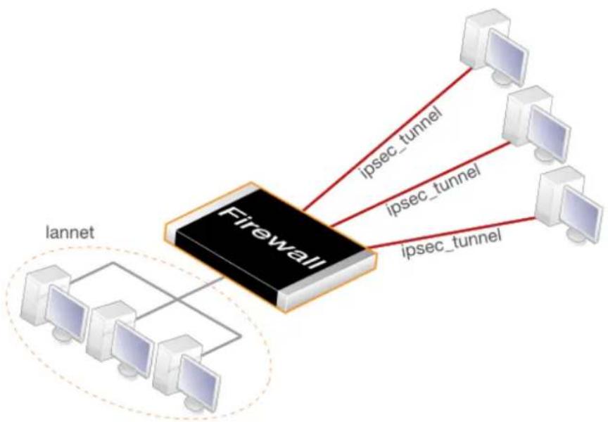
flowchart
graph TD
A["Firewall"] -->|ipsec_tunnel| B["Computer 1"]
A -->|ipsec_tunnel| C["Computer 2"]
A -->|ipsec_tunnel| D["Computer 3"]
A -->|ipsec_tunnel| E["Computer 4"]
A -->|ipsec_tunnel| F["Computer 5"]
A --> G["Iannet"]
style A fill:#000,stroke:#fff,color:#fff
style G fill:#fff,stroke:#000
There are two types of roaming clients:
A. The IPv4 addresses of the clients are already allocated.
B. The IPv4 addresses of clients are not known beforehand and must be handed out by NetDefendOS when the clients try to connect.
The setup steps for these two types of client are described next.
A. Client IP addresses are already allocated
the IPv4 addresses may be known beforehand and have been pre-allocated to the roaming clients before they connect. The client's IP address will be manually input into the VPN client software.
- Select the IKE version. Usually an in-built client, like the one in iOS or Windows, will require IKEv2.
- Set up user authentication. IKEv1 requires XAuth to be enabled on the tunnel object. IKEv2 requires that EAP is enabled. The authentication source for either can be one of the following:
• A Local User DB object which is internal to NetDefendOS.
- An external RADIUS server.
An internal user database is easier to set up and is assumed here. Changing this to an external server is simple to do later.
To implement user authentication with an internal database:
- Define a Local User DB object (let's call this object TrustedUsers).
- Add individual users to TrustedUsers. This should consist of at least a username and password combination.
The Group string for a user can be specified if its group's access is to be restricted to certain source networks. Group can be specified (with the same text string) in the Authentication section of an IP object. If that IP object is then used as the Source Network of an IP policy in the IP rule set, that policy will only apply to a user if their Group string matches the Group string of the IP object.

Note
Group has no meaning in Authentication Rules.
- Create a new User Authentication Rule with the Authentication Source set to TrustedUsers. The other parameters for the rule are listed below:
| Agent | Auth Source | Src Network | Interface | Client Source IP |
| XAUTH (IKEv1) or EAP (IKEv2) | Local | all-nets | any | all-nets (0.0.0.0/0) |
- The IPsec Tunnel object ipsec_tunnel should have the following parameters:
• Set Local Network to lannet.
• Set Remote Network to all-nets
• Set Remote Endpoint to all-nets.
- For IKEv1, set Encapsulation mode to Tunnel. IKEv2 always uses Tunnel and it does not need to be set.
- Set the IKE and IPsec algorithm proposal lists to match the capabilities of the clients.
- No routes can be predefined so the option Add route dynamically should be enabled for the tunnel object. If all-nets is the destination network, the option Add route statically should be disabled (this is usually only used with Lan-to-LAN tunnels).

Note
The option to dynamically add routes should not be enabled in LAN-to-LAN tunnel scenarios.
- For IKEv1, enable the property Require IKE XAuth user authentication for inbound IPsec tunnels.
For IKEv2, set the EAP property to be EAP Server.
NetDefendOS will search for the first matching XAUTH rule in the authentication rules when a client tries to connect.
- The IP rule set should contain the following single IP policy:
| Action | Src Interface | Src Network | Dest Interface | Dest Network | Service |
| Allow | ipsec_tunnel | all-nets | lan | lannet | all_services |
Once an Allow IP policy permits the connection to be set up, bidirectional traffic flow is allowed which is why only one policy is used here. Instead of all-nets being used in the above, a more secure defined IP object could be used which specifies the exact range of the pre-allocated IP addresses.
B. Client IP addresses are handed out by NetDefendOS
If the client IP addresses are not known then they must be handed out by NetDefendOS. To do this the previous setup with predefined IPs must be modified with the following changes:
- If a specific IP address range is to be used as a pool of available addresses then:
• Create an IKE Config Mode Pool object and specify the address range in it.
- Set the Config Mode property of the IPsec Tunnel object to be Server and set the Config Mode Pool property to be the IKE Config Mode Pool object created in the previous step.
-
If client IP addresses are to be retrieved through DHCP:
-
Create an IP Pool object and in it specify the DHCP server to use. The DHCP server can be specified as a simple IP address or alternatively as being accessible on a specific interface. If an internal DHCP server is to be used then specify the loopback address 127.0.0.1 as the DHCP server IP address.
- Create an IKE Config Mode Pool object and associate set the source of its IPs to be the IP Pool object defined in the previous step.
- Set the Config Mode property for the IPsec Tunnel to be the value Server and then
select the IKE Config Mode Pool object created in the previous step.
IKE config mode is discussed further in Section 10.3.11, "Config Mode".
For a roaming clients example showing the actual configuration steps, go to Example 10.4, "PSK Based IPsec Tunnel for Roaming Clients Setup" in Section 10.3.7, "IPsec Roaming Clients". That section also discusses IPsec client configuration.
10.2.4. IPsec Roaming Clients with Certificates
If certificates are used with IPsec roaming clients instead of pre-shared keys then no Pre-shared Key object is needed and the other differences in the setup described above are:
- Upload a Root Certificate and a Gateway Certificate into NetDefendOS. The gateway certificate needs to have 2 parts added: a certificate file (usually with filetype .cer or .crt) and a private key file (with filetype .key). The root certificate needs just the certificate file added.
Uploading certificates to NetDefendOS is described further in Section 3.9.2, "Uploading and Using Certificates".
- When setting up the IPsec Tunnel object, specify the certificates to use under Authentication. This is done by doing the following:
a. Enable the X.509 Certificate option.
b. Select the Gateway Certificate.
c. Add the Root Certificate to use.
- The IPsec client software will need the same root certificate installed that was used in the previous step. IKEv2 client setup with certificates is described further in Section 10.3.13, "Setup for IKEv2 Roaming Clients".
The step to set an authentication rule is optional since this is additional security. As described above, XAuth is used with IKEv1 and EAP is used with IKv2. Both require that a username and password is entered which can then be authenticated against a local user database or an external RADIUS server.
Also review Section 3.9.4, "CA Server Access", which describes important considerations for certificate validation.

Tip: The Roaming VPN object can simplify IKEv2 setup
The IPsec roaming client setup steps described above are based on the base IPsec Tunnel object. NetDefendOS also provides the Roaming VPN object which simplifies IKEv2 roaming client setup when using certificates with EAP authentication. This is described in Section 10.3.15.2, "Roaming VPN".
A more detailed description of IKEv2 roaming client setup with certificates using a standard IPsec Tunnel object is given in Section 10.3.13, "Setup for IKEv2 Roaming Clients".
Using certificates with all IPsec use cases is discussed further in Section 10.3.8, "IPsec with Certificates".
10.2.5. L2TP/IPsec Roaming Clients with Pre-Shared Keys
The inbuilt L2TP client in Microsoft Windows means that L2TP is a popular choice for roaming client VPN scenarios. L2TP is usually encapsulated in IPsec to provide encryption with IPsec running in transport mode instead of tunnel mode.
Note that IKEv2 cannot be used with transport mode so IKEv1 must be used when configuring the tunnel.
The steps for L2TP over IPsec setup are:
- Create an IPv4 address object (let's call it l2tp_pool) which defines the range of IP addresses which can be handed out to clients. Note that this object is a normal address book object and not an IP Pool object.
The range chosen for this address object can be one of the following two types:
- A range taken from the internal network to which clients will connect. If the internal network is 192.168.0.0/24 then we might use the address range 192.168.0.10 to 192.168.0.20. The danger here is that an IP address might be accidentally used on the internal network and handed out to a client.
-
Use a new address range that is totally different to any internal network. This prevents any chance of an address in the range also being used on the internal network.
-
Define two other IP objects:
-
wan_ip which is the external public IPv4 address through which clients connect (assume this is on the wan interface).
-
lan_ip which is the internal IP address of the interface to which the internal network is connected (let's call this interface lan ).
-
Define a Pre-shared Key for the IPsec tunnel.
-
Define an IPsec Tunnel object (let's call this object ipsec_tunnel) with the following parameters:
• Make sure the IKE Version is set to IKEv1.
• Set Encapsulation Mode to Transport.
- Set Local Endpoint to wan_ip (specify all-nets instead if NetDefendOS is behind a NATing device).
• Set Remote Endpoint to all-nets.
- For Authentication select the Pre-shared Key object defined in the first step.
- Select the IKE and IPsec algorithm proposal lists to be used.
- When all-nets is the destination network, as is the case here, the advanced setting option Add route statically must also be disabled. This setting is enabled by default.
-
Define an PPTP/L2TP Server object (let's call this object l2tp_tunnel) with the following parameters:
-
Set Inner IP Address to lan_ip.
• Set Tunnel Protocol to L2TP. -
Set Outer Interface Filter to ipsec_tunnel.
- Set Outer Server IP to wan_ip.
- Set the Microsoft Point-to-Point Encryption setting to None only. Since IPsec encryption is already used, double encryption will degrade throughput.
- Set IP Pool to l2tp_pool.
- Enable Proxy ARP on the lan interface to which the internal network is connected.
- Under the Virtual Routing tab, make this interface a member of a specific routing table so that routes are automatically added to that table. Normally the main table should be selected.
6. For user authentication:
- Define a Local User DB object (let's call this object TrustedUsers).
- Add individual users to TrustedUsers. This should consist of at least a username and password combination.
The Group string for a user can also be specified. This is explained in the same step in the IPsec Roaming Clients section above.
• Define a User Authentication Rule:
| Agent | Auth Source | Src Network | Interface | Client Source IP |
| L2TP/PPTP/SSL VPN | Local | all-nets | l2tp_tunnel | all-nets (0.0.0.0/0) |
- To allow traffic through the L2TP tunnel the following IP policies should be defined in the IP rule set:
| Action | Src Interface | Src Network | Dest Interface | Dest Network | Service |
| Allow | l2tp_tunnel | l2tp_pool | any | int_net | all_services |
| Allow/NAT | l2tp_tunnel | l2tp_pool | ext | all-nets | all_services |
The second IP policy would be included to allow clients to surf the Internet via the lan interface on the D-Link firewall. This policy should have its Action property set to Allow and its Source Address Translation property set to NAT. A client will be allocated a private internal IP address which must be NATed if connections are then opened to the Internet via the firewall.
- Set up the client. Assuming Windows, the Create new connection option in Network Connections should be selected to start the New Connection Wizard. The key information to enter in this wizard is the resolvable URL of the firewall or alternatively its wan_ip IP address.
Then choose Network > Properties. In the dialog that opens choose the L2TP Tunnel and select Properties. In the new dialog that opens select the Networking tab and choose Force to L2TP. Now go back to the L2TP Tunnel properties, select the Security tab and click on the IPsec Settings button. Now enter the pre-shared key.
10.2.6. L2TP/IPsec Roaming Clients with Certificates
If certificates are used with L2TP roaming clients instead of pre-shared keys then the differences in the setup described above are as follows:
• The NetDefendOS date and time must be set correctly since certificates can expire.
- Load a Gateway Certificate and Root Certificate into NetDefendOS.
- When setting up the IPsec Tunnel object, specify the certificates to use under Authentication. This is done by:
i. Enable the X.509 Certificate option.
ii. Select the Gateway Certificate.
iii. Add the Root Certificate to use.
- If using the Windows L2TP client, the appropriate certificates need to be imported into Windows before setting up the connection with the New Connection Wizard.
The step to set up user authentication is optional since this is additional security to certificates.
Also review Section 3.9.4, "CA Server Access", which describes important considerations for certificate validation.
10.2.7. PPTP Roaming Clients
PPTP is simpler to set up than L2TP since IPsec is not used and instead relies on its own, less strong, encryption.
A major secondary disadvantage is not being able to NAT PPTP connections through a tunnel so multiple clients can use a single connection to the D-Link firewall. If NATing is tried then only the first client that tries to connect will succeed.
The steps for PPTP setup are as follows:
-
In the Address Book define the following IP objects:
-
A pptp_pool IP object which is the range of internal IP addresses that will be handed out from an internal network.
- An int_net object which is the internal network from which the addresses come.
- An lan_ip object which is the internal IP address of the interface connected to the internal network. Let us assume that this interface is lan.
-
An wan_ip object which is the external public address which clients will connect to (let's assume this is on the wan interface).
-
Define a PPTP/L2TP object (let's call it pptp_tunnel) with the following parameters:
-
Set Inner IP Address to ip_net.
• Set Tunnel Protocol to PPTP. - Set Outer Interface Filter to wan.
- Set Outer server IP to wan_ip.
• For Microsoft Point-to-Point Encryption it is recommended to disable all options
except 128 bit encryption.
- Set IP Pool to pptp_pool.
- Enable Proxy ARP on the lan interface.
• As in L2TP, enable the insertion of new routes automatically into the main routing table.
- Define a User Authentication Rule, this is almost identical to L2TP:
| Agent | Auth Source | Src Network | Interface | Client Source IP |
| L2TP/PPTP/SSL VPN Local all-nets pptp_tunnel | all-nets (0.0.0.0/0) |
- Now, create the following IP policies in the IP rule set:
| Action | Src Interface | Src Network | Dest Interface | Dest Network | Service |
| Allow | pptp_tunnel | pptp_pool | any | int_net | all_services |
| Allow/NAT | pptp_tunnel | pptp_pool | ext | all-nets | all_services |
As described for L2TP, the NAT IP policy lets the clients access the Internet via the D-Link firewall. This policy should have its Action property set to Allow and its Source Address Translation property set to NAT.
- Set up the client. For Windows, the procedure is exactly as previously described for L2TP but without entering the pre-shared key.
10.3. IPsec
This section discusses how to set up and use IPsec tunnels with NetDefendOS.
Note that a quick start checklist of setup steps for IPsec in typical scenarios can be found in the preceding VPN quickstart section in the following sections:
• Section 10.2.1, "IPsec LAN-to-LAN with Pre-shared Keys".
• Section 10.2.2, "IPsec LAN-to-LAN with Certificates".
• Section 10.2.3, "IPsec Roaming Clients with Pre-shared Keys".
• Section 10.2.4, "IPsec Roaming Clients with Certificates".
10.3.1. IPsec Principles
This section is a general discussion of the operation of IPsec and describes the various components, techniques and algorithms that are used in IPsec based VPNs.
Internet Protocol Security (IPsec) is a set of protocols defined by the Internet Engineering Task Force (IETF) to provide IP security at the network layer. An IPsec based VPN is made up of two parts:
• Internet Key Exchange protocol (IKE)
• IPsec protocols (AH/ESP/both)
The first part, IKE, is the initial negotiation phase, where the two VPN endpoints agree on which methods will be used to provide security for the underlying IP traffic. Furthermore, IKE is used to manage connections, by defining a set of Security Associations, SAs, for each connection. SAs are unidirectional, so there are usually at least two for each IPsec connection.
The second part is the actual IP data being transferred, using the encryption and authentication methods agreed upon in the IKE negotiation. This can be accomplished in a number of ways; by using IPsec protocols ESP, AH, or a combination of both.
The flow of events can be briefly described as follows:
• IKE negotiates how IKE should be protected
• IKE negotiates how IPsec should be protected
• IPsec moves data in the VPN
The following sections will describe each of these stages in detail.
10.3.1.1. Internet Key Exchange (IKE)
This section describes IKE, the Internet Key Exchange protocol, and the parameters that are used with it.
Encrypting and authenticating data is fairly straightforward, the only things needed are encryption and authentication algorithms, and the keys used with them. The Internet Key Exchange (IKE) protocol, IKE, is used as a method of distributing these "session keys", as well as providing a way for the VPN endpoints to agree on how the data should be protected.
IKE has three main tasks:
- Provide a means for the endpoints to authenticate each other
• Establish new IPsec connections (create SA pairs) - Manage existing connections
IKEv2 Should Be Used Instead of IKEv1
The IKE protocol comes in two version called IKEv1 and the newer IKEv2. NetDefendOS provides support for both versions but it is recommended to always use IKEv2, unless IKEv1 is required for compatibility with the remote tunnel peer. IKEv2 provides much faster tunnel setup times and provides features not available with IKEv1, such as better Diffie-Hellman negotiation.
This administration guide provides details for setting up IPsec using either IKEv1 or IKEv2. The material in this section is applicable to both IKE versions.
Security Associations (SAs)
IKE keeps track of connections by assigning a set of Security Associations, SAs, to each connection. An SA describes all parameters associated with a particular connection as well as the session keys used to encrypt/decrypt and/or authenticate/verify the transmitted data.
An SA is unidirectional and relates to traffic flow in one direction only. For the bidirectional traffic that is usually found in a VPN, there is therefore a need for more than one SA per connection. In most cases, two SAs will be created for each connection, one describing the incoming traffic, and the other the outgoing traffic.
IKE Negotiation
The process of negotiating session parameters consists of a number of phases and modes. These are described in detail in the sections below.
The flow of events can be summarized as follows:
IKE Phase-1
• Negotiate how IKE should be protected
IKE Phase-2
• Negotiate how IPsec should be protected
- Derive some fresh keying material from the key exchange in phase-1, to provide session keys to be used in the encryption and authentication of the VPN data flow
IKE and IPsec Lifetimes
Both the IKE and the IPsec connections have lifetimes values associated with them. These lifetimes prevent a connection from being used for too long before rekeying takes place. Neither lifetime can be lower than 40 seconds in NetDefendOS.
It is recommended that the lifetimes are equal to or greater than the following values:
• IKE lifetime - 600 seconds (10 minutes)
• IPsec lifetime - 300 seconds (5 minutes)
NetDefendOS rekeys IPsec security associations 30 seconds before lifetime expiry in order to have time for any resends. This will mean that when a lifetime is at the minimum of 40 seconds, the IPsec security associations will be rekeyed every 10 seconds. NetDefendOS will issue warning messages during reconfiguration if the lifetime values are too low.
IKE Algorithm Proposals
An IKE algorithm proposal list is a suggestion of how to protect IPsec data flows. The VPN device initiating an IPsec connection will send a list of the algorithms combinations it supports for protecting the connection and it is then up to the device at the other end of the connection to say which proposal is acceptable.
Upon receiving the list of supported algorithms, the remote peer will choose the algorithm combination that best matches its own proposal list, and reply by specifying which member of the list it has chosen. If no mutually acceptable proposal can be found, the responder will reply by saying that nothing on the list was acceptable, and possibly also provide a textual explanation for diagnostic purposes.
This negotiation to find a mutually acceptable algorithm combination is done not just to find the best way to protect the IPsec tunnel data but also to find the best way to protect the IKE negotiation itself.
Algorithm proposal lists contain not just the acceptable algorithm combinations for encrypting and authenticating data but also other IKE related parameters. Further details of the IKE negotiation and the other IKE parameters are described next.
IKE Phase-1 - IKE Security Negotiation
An IKE negotiation is performed in two phases. The first phase, phase 1, is used to authenticate the two VPN firewalls or VPN clients to each other, by confirming that the remote device has a matching Pre-Shared Key.
However, since we do not want to publish too much of the negotiation in plaintext, we first agree upon a way of protecting the rest of the IKE negotiation. This is done, as described in the previous section, by the initiator sending a proposal-list to the responder. When this has been done, and the responder accepted one of the proposals, we try to authenticate the other end of the VPN to make sure it is who we think it is, as well as proving to the remote device that we are who we claim to be. A technique known as a Diffie Hellman Key Exchange is used to initially agree a shared secret between the two parties in the negotiation and to derive keys for encryption.
Authentication can be accomplished through Pre-Shared Keys, certificates or public key encryption. Pre-Shared Keys is the most common authentication method today. PSK and certificates are supported by the NetDefendOS VPN module.
IKE Phase-2 - IPsec Security Negotiation
In phase 2, another negotiation is performed, detailing the parameters for the IPsec connection.
During phase 2 we will also extract new keying material from the Diffie-Hellman key exchange in phase 1 in order to provide session keys to use in protecting the VPN data flow.
If Perfect Forwarding Secrecy (PFS) is used, a new Diffie-Hellman exchange is performed for each phase 2 negotiation. While this is slower, it makes sure that no keys are dependent on any other previously used keys; no keys are extracted from the same initial keying material. This is to make sure that, in the unlikely event that some key was compromised, no subsequent keys can be derived.
Once the phase 2 negotiation is finished, the VPN connection is established and ready for traffic
to pass through it.
IKEv2 Should Be Used Instead of IKEv1
NetDefendOS supported both IKEv2 and IKEv1 but IPsec tunnels will default to using IKEv2 and this is the recommended setting. IKEv1 is considered obsolete. IKEv2 provides the following advantages over IKEv1:
- IKEv2 has security weaknesses removed that were present in IKEv1.
- IKEv2 specifies how rekeying, NAT-T and dead peer detection should be handled.
- IKEv2 has a shorter handshake period.
- IKEv2 allows mobIKE for roaming clients. See Section 10.3.16, "MOBIKE Support" for a further discussion of this topic.
- IKEv2 is under active improvement.
10.3.1.2. IKE Authentication
The possible methods of IKE authentication are the following:
- Manual Keying.
• Pre-shared Keys (PSKs). - Certificates.
These methods will now be examined further.
Manual Keying
The simplest way of configuring a VPN is by using a method called manual keying. This is a method where IKE is not used at all; the encryption and authentication keys as well as some other parameters are directly configured on both sides of the VPN tunnel. This is an outdated authentication method which NetDefendOS does not support.
PSK
Using a Pre-shared Key (PSK) is a method where the endpoints of the VPN share a secret key which can be either a text string or hexadecimal sequence.
- PSK Advantages
Pre-Shared Keying is useful for its simplicity of setup. Only a single key is needed for one tunnel which is manually shared between the tunnel endpoints.
- PSK Disadvantages
One thing that has to be considered when using Pre-Shared Keys is key distribution. How are the Pre-Shared Keys distributed to remote VPN clients and firewalls? This is a major issue, since the security of a PSK system is based on the PSKs being secret. Should one PSK be compromised, the configuration will need to be changed to use a new PSK.
Certificates
Each VPN endpoint has its own certificate, and one or more trusted root certificates.
Certificate authentication is based on the following:
• Each endpoint has the private key corresponding to the public key found in its certificate, and that nobody else has access to the private key.
• Each certificate has been signed by a third party that the remote endpoint trusts. This third party is normally a certificate authority (CA).
• Advantages of Certificates
A principal advantage of certificates is flexibility and scalability. For example, a large number of IPsec endpoints can be managed without having the same pre-shared key configured on all of them, which is often the case when using pre-shared keys and roaming clients. If a certificate becomes compromised, it can simply be revoked without reconfiguring every endpoint.
• Disadvantages of Certificates
The principal disadvantage of certificates is the added complexity. Certificate based authentication may be used as part of a larger public key infrastructure (PKI), making all VPN clients and firewalls dependent on third parties. In other words, there are more aspects that have to be configured, and there is more that can go wrong.
10.3.1.3. IPsec Protocols (ESP/AH)
The IPsec protocols are the protocols used to protect the actual traffic being passed through the VPN. The actual protocols used and the keys used with those protocols are negotiated by IKE.
There are two protocols associated with IPsec, AH and ESP. These are covered in the sections below.
AH (Authentication Header)
AH is a protocol used for authenticating a data stream.
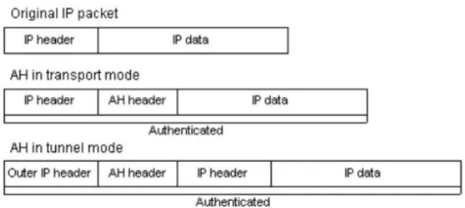
Figure 10.1. The AH protocol
AH uses a cryptographic hash function to produce a MAC from the data in the IP packet. This
MAC is then transmitted with the packet, allowing the remote endpoint to verify the integrity of the original IP packet, making sure the data has not been tampered with on its way through the Internet. Apart from the IP packet data, AH also authenticates parts of the IP header.
The AH protocol inserts an AH header after the original IP header. In tunnel mode, the AH header is inserted after the outer header, but before the original, inner IP header.
It should be noted that AH is rarely used and NetDefendOS does not currently support it.
ESP (Encapsulating Security Payload)
The ESP protocol inserts an ESP header after the original IP header, in tunnel mode, the ESP header is inserted after the outer header, but before the original, inner IP header.
All data after the ESP header is encrypted and/or authenticated. The difference with AH is that ESP also provides encryption of the IP packet. The authentication phase also differs in that ESP only authenticates the data after the ESP header; thus the outer IP header is left unprotected.
The ESP protocol is used for both encryption and authentication of the IP packet. It can also be used to do either encryption only, or authentication only.
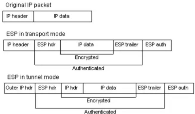
flowchart
graph TD
A["Original IP packet"] --> B["IP header"]
A --> C["IP data"]
D["ESP in transport mode"] --> E["IP header"]
D --> F["ESC hdr"]
D --> G["IP data"]
D --> H["ESC trailer"]
D --> I["ESP auth"]
J["ESC in tunnel mode"] --> K["Outer IP hdr"]
J --> L["ESC hdr"]
J --> M["IP hdr"]
J --> N["IP data"]
J --> O["ESP trailer"]
J --> P["ESP auth"]
Q["Encrypted"] --> R["Authenticated"]
S["Encrypted"] --> T["Authenticated"]
Figure 10.2. The ESP protocol
10.3.2. IPsec Tunnels in NetDefendOS
IPsec tunnels in NetDefendOS are defined by the IPsec Tunnel configuration object and this can be regarded as specifying an IPsec tunnel endpoint. An IPsec Tunnel object should also be regarded by the administrator as a logical NetDefendOS interface, with the same filtering, traffic shaping and configuration capabilities as Ethernet interfaces. Most importantly, an IPsec Tunnel object can be used as the Source Interface and/or Destination Interface in an IP Policy or other IP rule set entry.
Remote Initiation of Tunnel Establishment
When another D-Link firewall or other IPsec compliant networking product (also known as the remote endpoint) tries to establish an IPsec VPN tunnel to a local D-Link firewall, the list of currently defined IPsec tunnels in the NetDefendOS configuration is examined. If a matching tunnel definition is found, that tunnel is opened. The associated IKE and IPsec negotiations then take place, resulting in the tunnel becoming established to the remote endpoint.
The way NetDefendOS selects the IPsec Tunnel object to use when the tunnel is initiated by an
external device is described in more detail in Section 10.3.9, "IPsec Tunnel Selection".
Local Initiation of Tunnel Establishment
Alternatively, a user on a protected local network might try and access a resource which is located at the end of an IPsec tunnel. In this case, NetDefendOS sees that the route for the IP address of the resource is through a defined IPsec tunnel and establishment of the tunnel is then initiated from the local D-Link firewall.
IP Policies Control Decrypted Traffic
Note that an established IPsec tunnel does not automatically mean that all the traffic flowing from the tunnel is trusted. On the contrary, network traffic that has been decrypted will be checked against the IP rule set. When performing this check, the source interface of the traffic will be the associated IPsec tunnel since tunnels are treated like interfaces in NetDefendOS.
In addition, a Route or an Access rule may have to be defined for roaming clients in order for NetDefendOS to accept specific source IP addresses from the IPsec tunnel.
Returning IPsec Traffic
For network traffic going in the opposite direction, back into an IPsec tunnel, a reverse process takes place. First, the unencrypted traffic is evaluated by the IP rule set. If an IP policy and route matches, NetDefendOS tries to find an established IPsec tunnel that matches the criteria. If not found, NetDefendOS will try to establish a new tunnel to the remote endpoint specified by a matching IPsec tunnel definition.
No IP Policies Are Needed for the Enclosing IPsec Traffic
With IPsec tunnels, the administrator usually sets up IP policies that allow unencrypted traffic to flow into the tunnel (the tunnel being treated as a NetDefendOS interface). However, it is normally not necessary to set up IP policies that explicitly allow the packets that implement the IPsec tunnel itself (in other words, the outer part of the tunnel).
IKE and ESP packets are, by default, dealt with by the NetDefendOS's internal IPsec engine and the IP rule sets are not consulted.
This behavior can be changed in the IPsec advanced settings with the IPsec Before Rules setting. An example of why this might be done is if there are a high number of IPsec tunnel connection attempts coming from a particular IP address or group of addresses. This can degrade the performance of the NetDefendOS IPsec engine and explicitly dropping such traffic with an IP policy is an efficient way of preventing it reaching the engine. In other words, IP policies could be used for complete control over all the traffic related to an IPsec tunnel.
Monitoring Tunnel Health
The following methods are available with both IKEv1 and IKEv2 for monitoring IPsec tunnel health and re-establishing the tunnel if a problem is detected:
- Dead Peer Detection
Dead Peer Detection (DPD) is used to monitor IPsec tunnel health. It can optionally be enabled for a tunnel and it is recommended to always have it enabled (the default) unless the external IPsec peer does not support it. With roaming IPsec clients, DPD is the only option for monitoring tunnel health.
DPD monitors the aliveness of the tunnel by looking for traffic coming from the peer at the other end of the tunnel. If no traffic is seen within a certain length of time then NetDefendOS sends DPD-R-U-THERE messages to the peer to determine if it is still reachable.
If the peer does not respond after sending a series of DPD message messages then the peer is considered dead and the tunnel is closed. The tunnel will be re-established in the normal way, for example when NetDefendOS needs to send traffic through the tunnel or if an external IPsec peer initiates tunnel setup.
It should be noted that disabling DPD on a tunnel does not stop NetDefendOS responding to DPD-R-U-THERE messages from a peer, since the IPsec standard requires a response. However, disabling DPD does mean that NetDefendOS will not send out its own DPD-R-U-THERE messages.
The only IPsec tunnel property which can be changed for DPD is Interval which specifies the amount of time to wait after the last traffic seen before sending the first DPD message.

Note
Both Auto Establish and DPD could be used at the same time.
- Tunnel Monitoring
NetDefendOS provides tunnel monitoring as an addition to DPD for monitoring the health of an IPsec tunnel. Tunnel monitoring requires that an external host is available that is reachable through the tunnel with ICMP ping messages.
This feature is described further in Section 10.3.17, "IPsec Tunnel Monitoring".
10.3.3. IPsec Tunnel Properties
Below, is a summary of the key properties required with an IPsec Tunnel object. Understanding what these properties do before attempting to configure the tunnel is strongly recommended, since it is important that there is agreement with the remote tunnel peer.
- IKE Version
NetDefendOS supports both IKEv1 and IKEv2 and uses IKEv2 by default. It is recommended to use IKEv2 when possible as IKEv1 is now considered obsolete is usually only needed for compatibility with older equipment. This property can be set to a value of Auto which means IKEv2 will be tried first and if that fails then IKEv1 will be tried.
• Local and Remote Networks/Hosts
These are the subnets or hosts between which IP traffic will be protected by the VPN. In a LAN-to-LAN connection, these will be the network addresses of the respective LANs.
With IPsec roaming clients, the remote network will most likely be set to all-nets, since the client may connect from any network.
- Local Endpoint
By default, this property of an IPsec tunnel object is the IP address of the Ethernet interface being used for the connection. More specifically, the address is the IP address in the core route for the interface. If there are both IPv4 and IPv6 core routes for the interface then
NetDefendOS can make use of either the IPv4 or IPv6 address as the local endpoint for the IPsec tunnel.
Setting this property means the source address of the tunnel is a specific IP address. If this property is assigned an IP address, the administrator must also manually configure NetDefendOS to ARP publish the IP address on the sending interface. Doing this is described in Section 3.5.3, "ARP Publish".
The Local Endpoint property must be set if local clients behind the firewall are sending traffic through an IPsec tunnel which is established on a different interface. For example, the clients might be on the Ian interface but the IPsec tunnel endpoint might be the wan interface. In this case, the Local Endpoint property should be set to the IP address of the wan interface.
- Remote Endpoint
The remote endpoint (sometimes also referred to as the remote gateway) is the IP address of the peer at the other end of the IPsec tunnel. It can be specified as a single IP address or IP address range. If the firewall is the tunnel initiator then it should be a single IP address. If tunnels are initiated by connecting roaming clients then the remote endpoint will usually be the IP address range/network to which the clients belong.
The remote endpoint can be specified in any of the following ways: such
• As a single IPv4 address or IPv4 range/network.
• As a single IPv6 address IPv6 range/network.
- As an FQDN Address object. This is the recommended method, providing that DNS lookup is available to resolve an FQDN to an IP address. Creating FQDN address objects is described in Section 3.1.7, "FQDN Address Objects".
FQDN objects usually have to be used if the firewall is initiating LAN-to-LAN tunnel setup against multiple IP addresses. When the FQDN resolves to multiple IP addresses, NetDefendOS will try to initiate tunnel setup against each in turn until it is successful.
Note that the remote endpoint is not used in transport mode.
- Incoming Interface Filter
If set, the Incoming Interface filter property of a tunnel determines which interface NetDefendOS will listen on for incoming IPsec connections (this is sometimes referred to as the Source Interface). This property provides a means to specify that a particular tunnel is used for connections being received on a particular interface as it takes precedence over the normal procedure for selecting a tunnel.
- Local ID and Remote ID
The local and remote IDs are values sent by each side of the tunnel during the IKE negotiation and both can be used with either a pre-shared key or certificate based tunnel.
i. Local ID - this property of an IPsec Tunnel object represents the identity of the local VPN tunnel endpoint and this is the value presented to the remote peer during the IKE negotiation.
The property is set to only a single value but can be left blank when using certificates since the ID will be contained within the host certificate sent. If the certificate sent contains multiple IDs, this property can be set to specify which ID in the certificate to use.
The Enforce Local ID property can be enabled so that when NetDefendOS is acting as responder, the ID proposed by the initiator must match the Local ID value. The default behavior is to ignore the proposed ID.
ii. Remote ID - This property can be used to specify an ID list object. An ID list object contains one or more IDs. When using certificates, the certificate sent sent by a remote peer must contain an ID which matches one of the IDs in the list in order for the peer to be authenticated. Using the Remote ID property with certificates is explained further in Section 10.3.18, "Using ID Lists with Certificates".
NetDefendOS applies sanity checks on all remote IDs to ensure they are acceptable. Usually malformed IDs have a problem in the DN name. For example, a faulty remote ID name might be the following:
DN=D-Link, OU=One, Two, Three, DC=SE
If specified by the administrator, there will be an error message when the NetDefendOS configuration is committed. The corrected remote ID form is the following:
DN=D-Link, OU=One\,Two\,Three, DC=SE
- Originator IP Address
An IPsec Tunnel object's Originator IP property is a means to set the source IP address that flows inside the tunnel when the originator is NetDefendOS itself.
This IP will be needed in such cases as when log messages or ICMP ping messages are sent by NetDefendOS. Also, when NATing an IPsec tunnel's local network to the remote network, the originator IP will be the IP address that will be used as the NAT address. This address may need to be set manually if the automatic choice described below is not suitable.
There are two possible settings for this property:
i. LocalInterface
This is the default setting. In the Web Interface, this corresponds to enabling the option: Automatically pick the address of a local interface that corresponds to the local net. NetDefendOS automatically selects the source IP address in the following way:
- NetDefendOS looks at the IP address of all non-IPsec interfaces and uses the first IP address it finds that is within the range of the tunnel's local network.
With an HA cluster, this means the shared and private IP can be different.
- If no suitable address is found in the first step, use the second IP address from the tunnel's local network. This potentially be an IP address that is already used by a host in the network and if this is the case the IP address will need to be set manually as described below.
With an HA cluster, this means the shared and private IP will be the same.
ii. Manual
This option allows the administrator to choose a specific IP. It is possible to choose two IPs:
- The non-HA IP address. This is the IPv4 address that will be used except for cluster situations.
- The HA IP address. This address will be used in HA clusters as the shared and private IP.
If the local network for the tunnel is all-nets then NetDefendOS will not be able to assign an IP address and a value will have to be assigned manually.
Also note that a core route is automatically added to all routing tables so that the originator IP address is routed on core.
- Encapsulation Mode
IPsec can be used in one two modes:
i. Tunnel Mode
Tunnel mode indicates that the traffic will be tunneled to a remote device, which will decrypt/authenticate the data, extract it from its tunnel and pass it on to its final destination. This way, an eavesdropper will only see encrypted traffic going from one of the VPN endpoints to another.
Tunnel mode works by encrypting the entire packet, including the IP header. It is commonly used between two firewalls, with the firewalls acting as proxies for the clients behind them and are not the destination IP for the data.
NAT traversal is supported with tunnel mode.
ii. Transport Mode
In transport mode, only the IPsec data payload is encrypted. The IP header is not encrypted. This is typically used to secure a connection from a VPN client to the firewall, where the firewall is the destination IP. It is often used in conjunction with other tunneling protocols, such as GRE or L2TP, where the packet is first encapsulated by that protocol before being protected by IPsec.
NAT traversal is not supported with transport mode.
This setting will typically be set to Tunnel in most configurations. With IKEv2, only Tunnel should be used.
- Main/Aggressive Mode
The IKE negotiation has two modes of operation, main mode and aggressive mode.
The difference between these two is that aggressive mode will pass more information in fewer packets, with the benefit of slightly faster connection establishment, at the cost of transmitting the identities of the security firewalls in the clear.
It is recommended to not use aggressive mode in a roaming client scenario as this can increase the vulnerability to amplification attacks.
- IKE Encryption
This specifies the encryption algorithms used in the IKE negotiation, and depending on the algorithm, the size of the encryption key used.
The algorithms supported by NetDefendOS IPsec are:
• AES
- Blowfish
• Twofish
• Cast128
• 3DES
• DES
DES is only included to be interoperable with other older VPN implementations. The use of DES should be avoided whenever possible, since it is an older algorithm that is no longer considered to be sufficiently secure.
- IKE Authentication
This specifies the authentication algorithms used in the IKE negotiation phase.
The algorithms supported by NetDefendOS IPsec are:
• MD5
• SHA1
• SHA256
• SHA512
• AES-XCBC (IKEv2 only)

Caution: SHA1 and MD5 have weaknesses
SHA1 is considered to have weaknesses and should be used with caution. MDS is no longer considered to be a secure algorithm and should be avoided if possible.
• IKE DH Group
This specifies the Diffie-Hellman group to use for the IKE exchange. The available DH groups are discussed below in the section titled Diffie-Hellman Groups. Raising the group number from the default should be done with caution as more computing resources will be used for higher group numbers and could lead to unacceptable tunnel setup times on slower hardware platforms.
With IKEv1, the same DH group must be used at both ends of the tunnel. IKEv2 provides the ability for tunnel negotiation using overlapping groups.
• IKE Lifetime
This is the lifetime of the IKE connection and is specified as a number seconds.
Whenever the IKE lifetime expires, a new phase-1 exchange will be performed. If no data was transmitted in the last "incarnation" of the IKE connection, no new connection will be made until someone wants to use the VPN connection again. This value should be greater than the IPsec SA lifetime.
• PFS
With Perfect Forwarding Secrecy (PFS) disabled, initial keying material is "created" during the key exchange in phase-1 of the IKE negotiation. In phase-2 of the IKE negotiation, encryption and authentication session keys will be extracted from this initial keying material. By using PFS, completely new keying material will always be created upon re-key. Should one key be compromised, no other key can be derived using that information.
PFS is generally not needed, since it is very unlikely that any encryption or authentication
keys will be compromised.
• PFS DH Group
This specifies the Diffie-Hellman group to use with PFS. The available DH groups are discussed below in the section titled Diffie-Hellman Groups. Raising the group number from the default should be done with caution as more computing resources will be used for higher group numbers and could lead to unacceptable tunnel setup times on slower hardware platforms.
- IPsec DH Group
This specifies the Diffie-Hellman group to use for IPsec communication. The available DH groups are discussed below in the section titled Diffie-Hellman Groups. Raising the group number from the default should be done with caution as more computing resources will be used for higher group numbers and could lead to unacceptable tunnel setup times on slower hardware platforms.
- IPsec Encryption
The encryption algorithm that will be used on the protected IPsec traffic.
The encryption algorithms supported by NetDefendOS are as follows:
• AES
- Blowfish
- Twofish
- Cast128
• 3DES
• DES
• IPsec Authentication
This specifies the authentication algorithm used on the protected traffic.
This is not used when ESP is used without authentication, although it is not recommended to use ESP without authentication.
The authentication algorithms supported by NetDefendOS are as follows:
• MD5
• SHA1
• SHA256
• SHA512
• AES-XCBC (IKEv2 only)

Caution: SHA1 and MD5 have weaknesses
As stated previously with IKE algorithms, SHA1 is considered to have weaknesses and should be used with caution. MD5 is no longer considered to be a secure algorithm and should be avoided if possible.
• IPsec Lifetime
This is the lifetime of the IPsec connection following tunnel setup. It is specified in both time (seconds) and data amount (in Kbytes). Whenever either of these values is exceeded, a re-key will be initiated, providing new IPsec encryption and authentication session keys. If the VPN connection has not been used during the last re-key period, the connection will be terminated, and re-opened from scratch when the connection is needed again.
• Auto Establish
By default, LAN-to-LAN IPsec tunnels are established only at the time that traffic tries to flow through them. By enabling the IPsec tunnel property Auto Establish, LAN-to-LAN tunnels are established without any traffic flowing. This is useful in the following situations:
i. With LAN-to_LAN tunnels only (IKEv1 or IKEv2). It cannot be used with roaming clients.
ii. With route failover, a tunnel for the alternate route is always established.
iii. After a reconfigure operation is performed on NetDefendOS, the tunnels are immediately reestablished without waiting for any traffic to flow.
Assuming two IPsec tunnel endpoint A and B, it is recommended that auto establish is enabled on B only when both of the following criteria are true:
i. A cannot initiate an IKE negotiation to B. The reasons why it cannot be the initiator might be any of the following:
• B is behind a NATing device.
• A is using DNS to get the IP address of B.
• B receives its IP address via DHCP.
ii. The administrator decides that A must be able to initiate UDP/TCP connections through the tunnel without B having sent any packets. For example, there might be a server located behind B which clients located behind A need to reach.
• Diffie-Hellman Groups
Diffie-Hellman (DH) is a cryptographic protocol that allows two parties to establish a shared secret key over an insecure communications channel through a series of plain text exchanges. This property specifies one or more DH groups that can be used during the IKE negotiation. The higher the group number used, the greater the security. However, higher group numbers also require increased hardware processing resources so caution is advised when using high numbers.
The DH groups supported by NetDefendOS are the following:
• DH group 1 (768-bit).
• DH group 2 (1024-bit - the default setting).
• DH group 5 (1536-bit).
• DH group 14 (2048-bit).
• DH group 15 (3072-bit).
• DH group 16 (4096-bit).
• DH group 17 (6144-bit).
• DH group 18 (8192-bit).
When more than one DH group is specified for a tunnel, the greatest group number that matches both sides of the tunnel will be chosen.

Note: Using DH group 14 or above is recommended
It is recommended to use DH group 14 or above. If any group below 14 is used then it should be understood that the security provided will be greatly reduced. However, a group below 14 may be required for compatibility reasons.
10.3.4. IPsec Proposal Lists
To agree on the IPsec tunnel parameters, a negotiation process is performed. As a result of these negotiations, IKE and IPsec security associations (SAs) are established. A proposal list of supported algorithms is the starting point for the negotiation. Each entry in a proposal list defines parameters that the tunnel endpoint is capable of supporting.
There are two types of proposal lists that can be created in NetDefendOS for IPsec: IKE proposal lists and IPsec proposal lists. IKE lists are used during IKE Phase-1 (IKE Security Negotiation), while IPsec lists are using during IKE Phase-2 (IPsec Security Negotiation).
Some algorithm proposal lists are already defined by default in NetDefendOS for different scenarios and user defined lists can be added to these.
The following IKE algorithm lists and IPsec lists are already defined by default:
1. High
This consists of the following, shorter list of algorithms that provide higher security:
• AES
• SHA256
• SHA512
• AES-XCBC
2. Medium
This consists of the following, longer list of algorithms that provide less security but greater compatibility with older endpoint devices:
• 3DES
• AES
- Twofish
• SHA1
• SHA256
• SHA512
• AES-XCBC
Example 10.1. Creating and Using an IPsec Proposal List
This example shows how to create and use an IPsec algorithm proposal list. The 3DES and AES will be proposed as encryption algorithms. The hash functions SHA256 and SHA512 will be proposed for checking if the data packet is altered while being transmitted. Note that this example does not illustrate how to add the specific IPsec tunnel object. It will also be used in a later example.
Command-Line Interface
First, create a list of IPsec Algorithms:
gw-world:/> add IPsecAlgorithms esp-l2tptunnel
DES3Enabled=Yes
AESEnabled=Yes
SHA256Enabled=Yes
SHA512Enabled=Yes
Then, apply the algorithm proposal list to the IPsec tunnel:
gw-world:/> set Interface IPsecTunnel MyIPsecTunnel
IPsecAlgorithms=esp-12tptunnel
Web Interface
First, create a list of IPsec Algorithms:
-
Go to: Objects > VPN Objects > IPsec Algorithms > Add > IPsec Algorithms
-
Enter a name for the list, for example esp-l2tptunnel
-
Now, select the following:
• 3DES
• AES
• SHA256
• SHA512
- Click OK
Then, apply the algorithm proposal list to the IPsec tunnel:
-
Go to: Network > Interfaces and VPN > IPsec
-
Select the target IPsec Tunnel object
-
Select the previously created esp-l2tptunnel in the IPsec Algorithms control
-
Click OK
10.3.5. Pre-shared Keys
Either a Pre-Shared Key (PSK) or certificates are used to authenticate IPsec tunnels. PSKs are secrets that are shared by the communicating parties before an IPsec tunnel is established. To establish the tunnel, both parties must show that they know the common PSK. PSKs can be constructed like a text password but the more common method is to use a long hexadecimal value.
Random hexadecimal PSKs can be generated automatically through the Web Interface but they can also be generated through the CLI using the command pskgen (this command is described further in the separate CLI Reference Guide).
Beware of Non-ASCII Characters in a PSK on Different Platforms!
If a PSK is specified as a text string and not a hexadecimal value, the different encodings on different platforms can cause a problem with non-ASCII characters. Windows, for example, encodes PSKs containing non ASCII characters into UTF-16, while NetDefendOS uses UTF-8. Even though they can seem the same at either end of the tunnel, there will be a mismatch and this can sometimes cause problems when setting up a Windows L2TP client that connects to NetDefendOS.
Example 10.2. Creating and Using a PSK
This example shows how to create a Pre-shared Key and apply it to a VPN tunnel. Since regular words and phrases are vulnerable to dictionary attacks, they should not be used as secrets. Here the pre-shared key is a randomly generated hexadecimal key. Note that this example does not illustrate how to add the specific IPsec tunnel object.
Command-Line Interface
First create a Pre-shared Key. To generate the key automatically with a 64 bit (the default) key, use:
gw-world:/> pskgen MyPSK
To have a longer, more secure 512 bit key the command would be:
gw-world:/> pskgen MyPSK -size=512
Or alternatively, to add the Pre-shared Key manually, use:
gw-world:/> add PSK MyPSK Type=HEX PSKHex=<enter the key here>
Now apply the Pre-shared Key to the IPsec tunnel:
gw-world:/> set Interface IPsecTunnel MyIPsecTunnel PSK=MyPSK
Web Interface
First create a Pre-shared Key:
- Go to: Objects > Key Ring > Add > Pre-shared key
- Enter a name for the pre-shared key, for example MyPSK
- Choose Hexadecimal Key and click Generate Random Key to generate a key to the Passphrase textbox
- Click OK
Then, apply the pre-shared key to the IPsec tunnel:
- Go to: Network > Interfaces and VPN > IPsec
- Select the target IPsec tunnel object
- Under the Authentication tab, choose Pre-shared Key and select MyPSK
- Click OK
10.3.6. LAN-to-LAN Tunnels with Pre-shared Keys
A VPN can allow geographically distributed Local Area Networks (LANs) to communicate securely over the Internet. In a corporate context this means LANs at geographically separate sites can communicate with a level of security comparable to that existing if they communicated through a dedicated, private link.
Secure communication is achieved through the use of IPsec tunneling, with the tunnel extending from the VPN gateway at one location to the VPN gateway at another location. The D-Link firewall is therefore the implementer of the VPN, while at the same time applying normal security surveillance of traffic passing through the tunnel. This section deals specifically with setting up LAN-to-LAN tunnels created with a pre-shared Key (PSK).
A number of steps are required to set up LAN-to-LAN tunnels with PSK:
• Define a Pre-Shared Key (PSK) object.
• Define an IPsec Tunnel object.
- At minimum, the local network, the remote network and remote endpoint must be specified for the IPsec tunnel, along with the PSK defined in the first step.
- Set up IP Policy objects to allow traffic flow in either direction.
- A route to the remote network will be added automatically if the Add route statically property (this is called AutoInterfaceNetworkRoute in the CLI) is enabled and this property is always enabled by default for a tunnel.
If a custom route is required, this property should be disabled and the Route to the remote network added in the main routing table (or another table if an alternate is being used).
- Set up the peer at the other end of the tunnel in a similar way. The local and remote networks are reversed.

Tip: The D-Link VPN object can simplify LAN-to-LAN setup
The IPsec LAN-to-LAN setup described here is based on the standard IPsec Tunnel object. NetDefendOS also provides the D-Link VPN object which simplifies the setup of LAN-to-LAN IPsec between two D-Link firewalls using IKEv2 and either PSK or certificates. This is discussed further in Section 10.3.15.1, "LAN to LAN VPN".
Example 10.3. PSK Based LAN-to-LAN IPsec Tunnel Setup
This example describes how to configure an IPsec tunnel across the Internet to connect the head office network 172.16.1.0/24 on the lan interface with a branch office network 192.168.11.0/24. Assume that the branch office firewall Ethernet interface connected to the Internet has the public IP address 203.0.113.1.
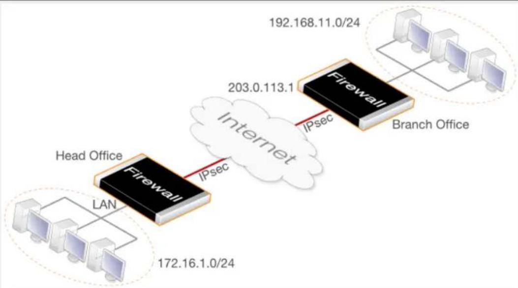
flowchart
graph LR
A["Head Office"] -->|IPsec| B["Firewall"]
B -->|IPsec| C["Internet"]
D["Branch Office"] --> E["Firewall"]
E --> F["192.168.11.0/24"]
G["Computer 1"] --> H["172.16.1.0/24"]
H --> I["Computer 2"]
J["Computer 3"] --> K["192.168.11.0/24"]
K --> L["Computer 4"]
M["Computer 5"] --> N["192.168.11.0/24"]
N --> O["Computer 6"]
P["Computer 7"] --> Q["192.168.11.0/24"]
Q --> R["Computer 8"]
S["Computer 9"] --> T["192.168.11.0/24"]
T --> U["Computer 10"]
It is assumed the default IKE and IPsec proposal list are used at either end of the tunnel.
Note that the Source Translation property of the IP policy used in this example can be left at the default value of Auto. When the source and destination IP addresses of a connection are both private IP addresses then no translation will be performed when the Auto option is selected. The Auto option is described further in Section 8.5, "Automatic Translation".
Command-Line Interface
A. Create a pre-shared key for IPsec authentication:
gw-world:/> add PSK my_scecret_key Type=ASCII PSKascii=somesecretascikey
B. Configure the IPsec tunnel:
gw-world:/> add Interface IPsecTunnel ipsec_hq_to_branch
LocalNetwork=172.16.1.0/24
RemoteNetwork=192.168.11.0/24
RemoteEndpoint=203.0.113.1
PSK=my_secret_key
C. Configure IP policies to allow traffic flow in both directions within the tunnel:
i. Add an IP policy to allow traffic to flow from local to remote network:
gw-world:/> add IPPolicy Name=hq_to_branch
SourceInterface=lan
SourceNetwork=172.16.1.0/24
DestinationInterface=ipsec_hq_to_branch
DestinationNetwork=192.168.11.0/24
Service=all_services
Action=Allow
ii. Add an IP policy to allow traffic to flow from remote to local network:
gw-world:/> add IPPolicy Name=branch_to_hq
SourceInterface=ipsec_hq_to_branch
SourceNetwork=192.168.11.0/24
DestinationInterface=lan
DestinationNetwork=172.16.1.0/24
Service=all_services
Action=Allow
D. Add a route that routes the remote network on the tunnel:
This step is not necessary if the route is added automatically (the default). If the AutoInterfaceNetworkRoute tunnel property has been disabled then the route must be added manually, as described below.
Change the context to be the routing table:
gw-world:/> cc RoutingTable main
Add the route:
gw-world:/main> add Route
Interface=ipsec_hq_to_branch
Network=192.168.11.0/24
Return to the default CLI context:
gw-world:/main> cc
gw-world:/>
Web Interface
A. Create a pre-shared key for IPsec authentication:
-
Go to: Objects > Key Ring > Add > Pre-Shared Key
-
Now enter:
-
Name: my_secret_key
• Shared Secret: Enter a secret passphrase
• Confirm Secret: Enter the secret passphrase again -
Click OK
B. Configure the IPsec tunnel:
-
Go to: Network > Interfaces and VPN > IPsec > Add > IPsec Tunnel
-
Now enter:
-
Name: ipsec_hq_to_branch
• Local Network: 172.16.1.0/24
• Remote Network: 192.168.11.0/24
• Remote Endpoint: 203.0.113.1 -
Under Authentication enter Pre-Shared Key: my_secret_key
4. Click OK
C. Configure IP policies to allow traffic flow in both directions within the tunnel:
i. Add an IP policy to allow traffic to flow from local to remote network:
-
Go to: Policies > Firewalling > Main IP Rules > Add > IP Policy
-
Now enter:
-
Name: hq_to_branch
-
Action: Allow
-
Under Filter enter:
-
Source Interface: Ian
• Source Network: 172.16.1.0/24 - Destination Interface: ipsec_hq_to_branch
• Destination Network: 192.168.11.0/24
• Service: all_services
4. Click OK
ii. Add an IP policy to allow traffic to flow from remote to local network:
-
Go to: Policies > Firewalling > Main IP Rules > Add > IP Policy
-
Now enter:
-
Name: branch_to_hq
-
Action: Allow
-
Under Filter enter:
-
Source Interface: ipsec_hq_to_branch
• Source Network: 192.168.11.0/24 - Destination Interface: Ian
• Destination Network: 172.16.1.0/24
• Service: all_services
4. Click OK
D. Add a route that routes the remote network on the tunnel:
This step is not necessary if the route is added automatically (the default). If the Add route statically tunnel property has been enabled then the route must be added manually, as described below.
- Go to: Network > Routing > Routing Tables > main > Add > Route
2. Now enter:
- Interface: ipsec_hq_to_branch
• Network: 192.168.11.0/24
3. Click OK
Now, configure the branch office firewall in a similar fashion. The local and remote gateway networks are reversed and the head office public IP now becomes the Remote Endpoint value. Note that the same PSK value must be used on both sides. Also, the proposal lists for IKE and IPsec should either be the same or at least have some overlap so cryptographic methods acceptable to both sides can be found during the IKE negotiation to set up the tunnel.
10.3.7. IPsec Roaming Clients
An employee who is on the move and who needs to access to a central corporate server from a notebook computer over the Internet from different locations is a typical example of a roaming client IPsec connection. There is a need for secure, authenticated access to the server, but the other issue is that a moving user's IP address is often not known beforehand. To handle unknown IP addresses, NetDefendOS can dynamically add routes to routing tables as IPsec tunnels are established.
IPsec Roaming Client Encryption and Authentication
When an IPsec tunnel is configured for roaming clients, authentication can be performed using either a pre-shared key (PSK) or using certificates. This is true for both IKEv1 and IKEv2 tunnels
Authentication of the client is usually done by the client sending a username and password credential combination. For IKEv1 this is handled with XAuth and IKEv2 handles it using EAP. XAuth and EAP will not be discussed in this section but both require that a separate Authentication Rule is set up that triggers when a client connects.
Most of this section applies to both IKEv1 and IKEv2. However, Section 10.3.13, "Setup for IKEv2 Roaming Clients" gives a detailed description of setting up IPsec with IKEv2 roaming clients using certificates and EAP authentication.

Tip: The Roaming VPN object can simplify IKEv2/EAP setup
NetDefendOS also provides the Roaming VPN object which simplifies IPsec roaming client setup. However this is only for IKEv2 tunnels using certificates with EAP authentication. This is discussed further in Section 10.3.15.2, "Roaming VPN".
Dealing with Unknown IP addresses
If the IP address of the roaming client is not known beforehand then NetDefendOS needs to create a route in its routing table dynamically as each client connects. In the example below this is the case and the IPsec tunnel is configured to dynamically add routes.
If clients are to be allowed to connect from any IP address then the Remote Network needs to be set to all-nets (IP address: 0.0.0.0/0) which will allow all existing IPv4-addresses to connect through the tunnel.
When configuring IPsec tunnels for roaming clients it is usually not necessary to add to or modify the algorithm proposal lists that are preconfigured in NetDefendOS.
Adding Routes for Roaming Clients Dynamically
Usually, a route in the NetDefendOS routing table should be added for each client as it connects. This can be done automatically by enabling the IPsec tunnel property Add route dynamically (this property is AddRouteToRemoteNet in the CLI.
At the same time the IPsec tunnel property Add route statically (AutoInterfaceNetworkRoute in the CLI) should be disabled since this is used for LAN-to-LAN tunnels and would add a route to the remote network (usually all-nets in this case) if it is left enabled.
Proxy ARP Publishing Client IP Addresses
It is possible to proxy ARP publish the IP addresses of connecting roaming clients on selected or all interfaces by assigning interface names to the Proxy ARP Interfaces property of the IPsec Tunnel object.
Positioning Of Roaming Client Tunnels in the Tunnel List
When a roaming client tries to open a tunnel to a D-Link firewall, NetDefendOS will search the list of configured IPsec Tunnel objects and will select the first matching tunnel it finds. As a rule of thumb, it is usually best to make sure that roaming client tunnels are placed after any LAN-to-LAN tunnels in the list. This makes sure that roaming client tunnels are not erroneously selected when a LAN-to-LAN tunnel was intended. A further discussion of this and the tunnel matching process in general can be found in Section 10.3.9, "IPsec Tunnel Selection".
PSK Based IPsec Tunnels for Roaming Clients
The following example shows how a PSK based tunnel can be set up.
Example 10.4. PSK Based IPsec Tunnel for Roaming Clients Setup
This example describes how to configure an IPsec tunnel at the head office firewall for roaming clients that connect to it to gain remote access to the protected network 172.16.1.0/24 which is on the lan interface.
It is assumed the default NetDefendOS IKE and IPsec proposal list are used on the firewall and that the clients will use proposal lists that will result in an acceptable match during the IKE negotiation phase of tunnel setup.
Note that the Source Translation property of the IP policy used in this example can be left at the default value of Auto. When the source and destination IP addresses of a connection are both private IP addresses then no translation will be performed when the Auto option is selected. The Auto option is described further in Section 8.5, "Automatic Translation".
Command-Line Interface
A. Create a pre-shared key for IPsec authentication:
gw-world:/> add PSK my_scecret_key Type=ASCII PSKascii=somesecretascikey
B. Configure the IPsec tunnel:
gw-world:/> add Interface IPsecTunnel ipsec_roaming
LocalNetwork=172.16.1.0/24
RemoteNetwork=all-nets
PSK=my_secret_key
AddRouteToRemoteNet=Yes
AutoInterfaceNetworkRoute=No
C. Create an IP policy to allow traffic flow from clients:
gw-world:/> add IPPolicy Name=roaming_clients_to_hq
SourceInterface=ipsec_roaming
SourceNetwork=all-nets
DestinationInterface=lan
DestinationNetwork=172.16.1.0/24
Service=all_services
Action=Allow
Web Interface
A. Create a pre-shared key object for IPsec authentication:
1. Go to: Objects > Key Ring > Add > Pre-Shared Key
2. Now enter:
• Name: Enter a name for the key, for example my_secret_key
• Shared Secret: Enter a secret passphrase
• Confirm Secret: Enter the secret passphrase again
- Click OK
B. Configure the IPsec tunnel object:
1. Go to: Network > Interfaces and VPN > IPsec > Add > IPsec Tunnel
2. Now enter:
• Name: ipsec_roaming
• Local Network: 172.16.1.0/24
• Remote Network: all-nets
- Under Authentication enter Pre-Shared Key: my_secret_key
4. Under Advanced:
- Enable Add route dynamically
- Disable Add route statically
- Click OK
C. Create an IP policy to allow traffic flow from clients:
-
Go to: Policies > Firewalling > Main IP Rules > Add > IP Policy
-
Now enter:
-
Name: client_to_lan
-
Action: Allow
-
Under Filter enter:
-
Source Interface: ipsec_roaming
- Source Network: all-nets
-
Destination Interface: Ian
• Destination Network: 172.16.1.0/24
• Service: all_services -
Click OK
The Local Endpoint Property
In the situation where clients are initiating IPsec connections to the firewall, the usual situation is that the client will send the initial IKE request to the IP address bound to a physical interface.
However, if there are other IP addresses being ARP published on the interface and IKE requests are being sent to these addresses, the IPsec tunnel property Local Endpoint is used to specify the IP addresses on which IKE requests will be accepted.
The Local Endpoint property is never used if NetDefendOS is initiating the IPsec tunnel connection.
The Client's Inner and Outer IPs Should Be Different
With IKEv1, NetDefendOS requires that a roaming client's inner and outer IP addresses for the tunnel should be different. If they are the same, connections will be dropped by NetDefendOS and a ruleset_drop_packet log message will be generated containing "rule=Default_Access_Rule".
If the IP addresses must be the same, the situation can be corrected by using separate routing tables for the tunnel itself and the traffic the tunnel carries. Alternatively, NetDefendOS can allocate a unique IP address to clients from an IP pool using Config Mode.
Simplifying Setup with the Roaming VPN Object
This section has discussed setup for roaming clients based on an IPsec Tunnel object. Setup can be simplified by using a Roaming VPN object. This object hides the IPsec tunnel properties not relevant to roaming client connection and also simplifies client authentication by not requiring a separate Authentication Rule object.
A full discussion of the Roaming VPN object can be found in Section 10.3.15, "Using IPsec Profiles".
Configuring IPsec Roaming Clients
Depending on the type of client used with IPsec, its configuration might require any of the following changes:
- Specify the URL or IP address of the D-Link firewall so the client can locate the remote tunnel endpoint.
- Specify the pre-shared key (PSK) of one is used for authentication. Alternatively, install certificates if those are required for authentication (certificate usage is detailed in the section that follows).
- Specify the IKE and IPsec algorithms used so they can agree with the proposal list that NetDefendOS will use.
- Specify if the client will use config mode.
There are a variety of IPsec client software products available from third parties and also a number of IPsec clients that are already built into certain computing platforms. The network administrator should use the client that is best suited to their needs.
The only vendor specific IPsec client which is discussed in this publication are the following:
- The Windows IPsec client (Windows 7 and later) in Section 10.3.13, "Setup for IKEv2 Roaming Clients".
- The Apple iOS™ IPsec client in Section 10.3.14, "Setup for iOS Roaming Clients".
10.3.8. IPsec with Certificates
This section is a general discussion about using certificates instead of PSKs for IPsec with LAN-to-LAN and IKEv1 roaming clients scenarios. Note that setting up IPsec with IKEv2 roaming clients using certificates and EAP authentication is described separately in Section 10.3.13, "Setup for IKEv2 Roaming Clients" and is not covered in this section.
Using CA Signed Certificates
Using CA signed certificates is a method of authentication that relies on each tunnel endpoint having the following two certificates:
- A CA root certificate which will be used to validate the CA signed gateway certificate send by the remote tunnel endpoint. This consists of a single public key file.
- A CA signed gateway certificate (also known as a host certificate) which will be used by the endpoint to identify itself. This consists of two files which contain the public and private keys respectively.
It should be noted that the gateway certificate used will be validated by NetDefendOS so if the root certificate required for this is different from the root certificate mentioned in the previous point then that other root certificate and any associated certificate chain need to uploaded to the firewall.
Uploading certificate files to NetDefendOS is described in Section 3.9.2, "Uploading and Using Certificates". Once they are uploaded, they can then be referenced when defining an IPsec Tunnel object in the NetDefendOS configuration.
When using CA signed certificates, it is the responsibility of the administrator to acquire the
appropriate CA signed certificate from an issuing authority. With some systems, such as Windows Server ^™ systems, there is built-in access to a CA server. For more information on CA server issued certificates see Section 3.9, "Certificates".
For LAN-to-LAN tunnels the best security is provided by certificates signed by an organization's own private CA server since no one outside of an organization should have access to the certificates used. This might also be possible with roaming clients but using a public CA may be the only viable choice if IPsec connection is to be made available for the general public.
Using Self-signed Certificates
IPsec tunnel authentication in NetDefendOS can be based on self-signed certificates instead of CA signed certificates. Configuration requires having a pair of different self-signed certificates which are both present on the firewall (or other network device) on either side of the tunnel but have their roles as root and gateway certificate reversed at either side.
Suppose the self-signed certificate pair are called cert_A which is uploaded to or created on firewall firewall_A and cert_B which is created on or uploaded to firewall_B. On firewall_A, cert_A is the gateway certificate and cert_B is the root certificate for the tunnel. On firewall_B, the situation is reversed: cert_B is the gateway certificate and cert_A is the root certificate for the tunnel.
Note that if cert_A was created on firewall_A, it should not need to be uploaded and its private key is already available in the key store of firewall_A. When cert_B is loaded onto firewall_A, it is stored as a root certificate without a private key file. The situation will be the reverse on firewall_B.
Using self-signed certificates in a live production environment is not recommended as they defeat the purpose of a public key infrastructure (PKI). Using a pre-shared key (PSK) instead would be simpler to implement and would provide a similar level of security. However, self-signed certificates may be appropriate for some specific use cases.
Using Certificate Chains
Where there is a certificate chain between the root certificate and the gateway certificate for the IPsec tunnel, all the intermediate certificates in the chain must be uploaded and then configured as root certificates for the tunnel.
Setup Examples
The examples that follow are based on the previous examples of IPsec setup for LAN-to-LAN and roaming client tunnels but these have been modified to use certificates instead of PSKs for authentication.
Example 10.5. Certificate Based LAN-to-LAN IPsec Tunnel Setup
This example describes how to configure an IPsec tunnel across the Internet which connects the local network 172.16.1.0/24 on the lan interface of a local D-Link firewall to the network 192.168.11.0/24 behind a remote networking device that supports IPsec. The remote device could be another D-Link firewall.
Assume that the IPsec tunnel end point for the remote device's interface is the public IP address 203.0.113.1.
The default NetDefendOS IKE and IPsec proposal lists will be used.
Command-Line Interface
A. Upload the required certificate files to NetDefendOS using SCP
Doing this is described further in Section 3.9.2, "Uploading and Using Certificates".
B. Configure the IPsec tunnel:
gw-world:/> add Interface IPsecTunnel ipsec_local_to_remote_tunnel
LocalNetwork=172.16.1.0/24
RemoteNetwork=192.168.11.0/24
RemoteEndpoint=203.0.113.1
AuthMethod=Certificate
GatewayCertificate=my_host_cert
RootCertificates=my_root_cert
C. Configure IP policies to allow traffic flow in both directions within the tunnel:
i. Add an IP policy to allow traffic to flow from local to remote network:
gw-world:/> add IPPolicy Name=local_to_remote_traffic
SourceInterface=lan
SourceNetwork=172.16.1.0/24
DestinationInterface=ipsec_local_to_remote_tunnel
DestinationNetwork=192.168.11.0/24
Service=all_services
Action=Allow
ii. Add an IP policy to allow traffic to flow from remote to local network:
gw-world:/> add IPPolicy Name=remote_to_local_traffic
SourceInterface=ipsec_remote_to_local_tunnel
SourceNetwork=192.168.11.0/24
DestinationInterface=lan
DestinationNetwork=172.16.1.0/24
Service=all_services
Action=Allow
D. Add a route that routes the remote network on the tunnel:
This step is not necessary if the route is added automatically (the default). If the AutoInterfaceNetworkRoute tunnel property has been disabled then the route must be added manually, as described below.
Change the context to be the routing table:
gw-world:/> cc RoutingTable main
Add the route:
gw-world:/main> add Route Interface=ipsec_local_to_remote_tunnel
Network=192.168.11.0/24
Return to the default CLI context:
gw-world:/main> cc
gw-world:/>
Web Interface
A. Upload the required certificates with the following:
-
Go to: Objects > General > Key Ring > Add > Certificate
-
Specify a suitable name for the certificate, for example my_cert
-
Select Uploadas the source
-
Select Browse
-
Use the file chooser to select a certificate file and any related private key file.
-
Click OK
B. Configure the IPsec tunnel:
-
Go to: Network > Interfaces and VPN > IPsec > Add > IPsec Tunnel
-
Now enter:
- Name: ipsec_local_to_remote_tunnel
• Local Network: 172.16.1.0/24
• Remote Network: 192.168.11.0/24
• Remote Endpoint: 203.0.113.1
-
For Authentication enter:
-
Choose X.509 Certificates as the authentication method
-
Root Certificate(s): Select the relevant CA server root and add it to the Selected list
• Gateway Certificate: Choose the relevant firewall certificate -
Click OK
C. Configure IP policies to allow traffic flow in both directions within the tunnel:
i. Add an IP policy to allow traffic to flow from local to remote network:
-
Go to: Policies > Firewalling > Main IP Rules > Add > IP Policy
-
Now enter:
-
Name: local_to_remote_traffic
• Action: Allow -
Under Filter enter:
-
Source Interface: Ian
• Source Network: 172.16.1.0/24 - Destination Interface: ipsec_local_to_remote_tunnel
• Destination Network: 192.168.11.0/24
- Service: all_services
4. Click OK
ii. Add an IP policy to allow traffic to flow from remote to local network:
- Go to: Policies > Firewalling > Main IP Rules > Add > IP Policy
-
Now enter:
-
Name: remote_to_local_traffic
-
Action: Allow
-
Under Filter enter:
-
Source Interface: ipsec_local_to_remote_tunnel
• Source Network: 192.168.11.0/24 - Destination Interface: Ian
• Destination Network: 172.16.1.0/24
• Service: all_services
4. Click OK
D. Add a route that routes the remote network on the tunnel:
This step is not necessary if the route is added automatically (the default). If the Add route statically tunnel property has been enabled then the route must be added manually, as described below.
- Go to: Network > Routing > Routing Tables > main > Add > Route
-
Now enter:
-
Interface: ipsec_local_to_remote_tunnel
• Network: 192.168.11.0/24
3. Click OK
Now, configure the remote network device in a similar fashion. The local and remote networks are reversed and the local public IP now becomes the Remote Endpoint value.
Example 10.6. Certificate Based IPsec Tunnels for Roaming Clients
This example describes how to configure an IPsec tunnel for the head office D-Link firewall so that roaming clients can get remote access. The head office network uses the 203.0.113.0/24 network with the public firewall IP address wan_ip.
Command-Line Interface
A. Upload the required certificate files to NetDefendOS using SCP
Doing this is described further in Section 3.9.2, "Uploading and Using Certificates".
B. Configure the IPsec tunnel:
gw-world:/> add Interface IPsecTunnel roaming_client_tunnel
LocalNetwork=203.0.113.0/24
RemoteNetwork=all-nets
AuthMethod=Certificate
GatewayCertificate=my_host_cert
RootCertificates=my_root_cert
AddRouteToRemoteNet=Yes
AutoInterfaceNetworkRoute=No
RemoteEndpoint=all-nets
C. Finally, configure IP policies to allow the traffic to flow inside the tunnel.
Web Interface
A. Upload the required certificates with the following:
-
Go to: Objects > General > Key Ring > Add > Certificate
-
Specify a suitable name for the certificate, for example my_cert
-
Select Uploadas the source
-
Select Browse
-
Use the file chooser to select a certificate file and any related private key file.
-
Click OK
B. Configure the IPsec tunnel:
-
Go to: Network > Interfaces and VPN > IPsec > Add > IPsec Tunnel
-
Now enter:
-
Name: roaming_client_tunnel
- Local Network: 203.0.113.0/24 (This is the local network that the roaming users will connect to)
- Remote Network: all-nets
-
Remote Endpoint: (None)
-
For Authentication enter:
-
Choose X.509 Certificates as the authentication method
-
Root Certificate(s): Select the relevant CA server root and add it to the Selected list
• Gateway Certificate: Choose the relevant firewall certificate -
Under Advanced:
-
Enable Add route dynamically
• Disable Add route statically
5. Click OK
C. Finally, configure IP policies to allow the traffic to flow inside the tunnel.
Troubleshooting Certificates
The following should be considered when troubleshooting problems with certificate based IPsec tunnels:
- Check that the correct certificates have been used for the right purposes.
- Check that the certificate .cer and .key files have the same filename. For example, my_cert.key and my_cert.cer.
- Check that the certificates have not expired. Certificates have a specific lifetime and when this expires they cannot be used and new certificates must be issued.
- Check that the NetDefendOS date and time is set correctly. If the system time and date is wrong then certificates can appear as being expired when, in fact, they are not.
- Consider time-zone issues with newly generated certificates. The D-Link firewall's time zone may not be the same as the CA server's time zone and the certificate may not yet be valid in the local zone.
- Disable CRL (revocation list) checking to see if CA server access could be the problem. CA Server issues are discussed further in Section 3.9.4, "CA Server Access".
10.3.9. IPsec Tunnel Selection
When an external network device initiates the setting up of an IPsec tunnel and the firewall acts as the responder, NetDefendOS must choose which IPsec Tunnel object in the configuration best matches the incoming connection request. This section describes how NetDefendOS makes this choice. Note that when the firewall is the tunnel initiator, no search is required since the tunnel object to use will be clear.
IPsec Tunnel Object Ordering is Important
When looking for an IPsec Tunnel object match, NetDefendOS scans the configured tunnel list from top to bottom and stops the search when it finds a match. For this reason, the ordering of tunnels in the list can be important. The following rule of thumb should be followed for correct placement in the tunnel list: tunnels with narrower criteria should be placed higher.
When following this rule, LAN-to-LAN tunnels should nearly always be placed before roaming client tunnels because LAN-to-LAN tunnels will usually have much narrower matching criteria than roaming client tunnels. For example, a roaming client tunnel will often have its Remote Network property set to all-nets whereas a LAN-to-LAN tunnel will usually have that property set to a much narrower specific network or range.
The Tunnel Selection Stages
As NetDefendOS goes through the IP Tunnel object list from first to last, it finds a match using the following three stage process:
Stage 1 - IKE SA Setup
The first stage involves trying to set up an IKE SA which is the basis for a secure control channel between the local and remote peer. The configuration properties used are:
i. Local Endpoint.
ii. Remote Endpoint.
iii. Incoming Interface Filter.
iv. DH Group
v. IKE algorithms.
Stage 2 - Authentication
In the second stage the peers authenticate themselves to each other. The matching criteria are:
i. Authentication Method
ii. Local ID - If specified, this must be acceptable to the remote peer. If not specified, and certificates are used, a local ID specified in the tunnels host certificate must be acceptable to the remote peer.
iii. Remote ID - If specified, the remote peer's ID must match one entry in the ID List assigned to this property. This is explained further in Section 10.3.18, "Using ID Lists with Certificates".
Stage 3 - IPsec SA Setup
In the final stage, the IPsec SA is negotiated. This is an addition to stage 2.
i. Local Network.
ii. Remote Network.
iii. IPsec Algorithms.
iv. Encapsulation Mode.
v. PFS/DH Group.
vi. Setup SA Per.
After the above three stages have been processed, the tunnel should be established.
10.3.10. IPsec IPv6 Support
IPsec tunnels in NetDefendOS provide IPv6 support in the following ways:
- For tunnel establishment. In other words, the outer part of the tunnel. This section only deals with this aspect of IPv6 usage with IPsec.
- For IPv6 traffic flowing inside the tunnel. This is discussed further in Section 3.2, "IPv6 Support".
IPv6 Must Be Manually Enabled on Relevant Ethernet Interfaces
By default, IPv6 is disabled on all Ethernet interfaces. For IPv6 to function with IPsec, IPv6 must be enabled on the Ethernet interfaces IPsec will use for connection. Enabling IPv6 on Ethernet interfaces is described in Example 3.12, "Enabling IPv6 on an Ethernet Interface".
IPv6 Usage with IPsec Tunnels
The following is a list of the IPsec components where IPv6 addresses can be used instead of IPv4:
- The Local Network and Remote Network properties of an IPsec Tunnel object can be IPv6 networks.
- The Local Endpoint and Remote Endpoint properties of an IPsec Tunnel object can be IPv6 addresses.
Note that the Local Endpoint and Remote Endpoint could both be IPv6 addresses but the tunnel can still carry IPv4 traffic. In other words, the endpoints could be IPv6 but the local and remote networks could be IPv4.
- IKE Config Mode Pool objects can use a pool of IPv6 addresses.
• Both CRL and CA lookup can be done using IPv6 addresses.
• The FQDN for the Remote Endpoint can resolve to an IPv6 address.
- IPsec Tunnel object properties cannot take both IPv4 and IPv6 addresses at the same time. However, some properties might not have a value assigned and will take the default value of
- The IP address authenticated using XAuth (with IKEv1) or EAP (with IKEv2) can be IPV4 or IPv6. This is discussed further in Section 9.2.5, "Authentication Rules".

Note: Tunnel monitoring requires an IPv4 address
The IPsec tunnel monitoring features supports an IPv4 address only for the remote host. This feature is described in Section 10.3.17, "IPsec Tunnel Monitoring".
10.3.11. Config Mode
IKE Configuration Mode (Config Mode) is an extension to IKE that allows NetDefendOS to provide configuration information to remote IPsec clients. It is used to dynamically configure IPsec roaming clients with IP addresses, and to allocate other types of address information. Either IPv4 or IPv6 addresses can be allocated, although IPv6 cannot be used with IP Pool objects, as explained below.
Config Mode Pools
One or more IKE Config Mode Pool objects can be created in NetDefendOS. No pools are predefined. The way a pool obtains its addresses is determined by setting its IP Pool Type property to one of the following:
• Pre-defined IP Pool Object
A range of IPv4 addresses to be handed out are taken from a separate IP Pool object in the NetDefendOS configuration. See Section 5.5, "IP Pools" for information about configuring these type of objects.
- Static IP Pool
Instead of using an IP Pool object, a range of addresses can be specified directly or an Address Book object can be specified. This option must be used for IPv6 addresses.
This option also allows a Netmask property to be entered. It should be noted that with IKv2 tunnels, this netmask value has no meaning and is always set by NetDefendOS to be 255.255.255.255.
Optional IKE Config Mode Pool Properties
The following IKE Config Mode Pool object properties can also be sent to the client. NetDefendOS itself does nothing with these values except forward them to the client.
DNS The IP address of the DNS used for URL resolution (already provided by an IP Pool).
NBNS/WINS The IP address for NBNS/WINS resolution (already provided by an IP Pool).
DHCP Instructs the host to send any internal DHCP requests to this address.
Subnets For IPv4 only, list of the subnets that the client can access.
Prefixes For IPv6 only, this is the IPv6 subnet that the client can access. An example prefix value could be 2001:DB8::/64.
Example 10.7. Creating an IKE Config Mode Pool
In this example, the Config Mode Pool object is enabled by associating it with an already configured IP Pool object called ip_pool1.
Command-Line Interface
gw-world:/> add ConfigModePool
IPPoolType=PreDefined
IPPool=my_ip_pool
Web Interface
- Go to: Objects > VPN Objects > IKE Config Mode Pool
- Select Use a predefined IPPool object
- Choose my_ip_pool from the IP Pool object list
- Click OK
After defining the config mode pool object, the remaining task is to associate the pool with the IPsec Tunnel.
Enabling Config Mode on an IPsec Tunnel
Changing the value of the Config Mode property of an IPsec Tunnel object enables the ability to hand out IP addresses to connecting roaming clients from a predefined pool of IP addresses.
The Config Mode property can take one of the following values:
• None
Config mode is disabled. The tunnel's local and remote network property settings decide the protected networks.
- Client
This allows NetDefendOS to act like a roaming client and receive the IP address it will use as its local endpoint inside the tunnel from the remote IPsec peer. Optionally a DNS server address can also be allocated by the remote peer. This option can be used with both IKEv1 and IKEv2 and is described in more depth at the end of this section.
- Server
This option means that NetDefendOS will allocate IP addresses to a connecting peer from a predefined pool of addresses. An associated Config Mode Pool must also be specified which is the source of the addresses.
• RADIUS/LocalDB
This option allows the IP address to be assigned to the user based on the method used for user authentication, which is decided by the triggering Authentication Rule. This option can be used with either IKEv1 XAuth authentication or IKEv2 EAP authentication.
If authentication is performed using a Local User Database then the IP handed out will be the value assigned to the Static Client IP Address property of the relevant User object.
If authentication is performed using an external RADIUS server then the server must be configured so that it sends back a Framed-IP-Address message with the allocated IP address when the user is authenticated.
Note that the allocation of IP addresses using this method is not available when using a Roaming VPN object to simplify roaming IPsec client setup.
Example 10.8. Enabling Config Mode on an IPsec Tunnel
Assume that an IKE Config Mode Pool object called my_cfg_pool and an IPsec Tunnel called my_ipsec_tunnel already exists. This example shows how to enable config mode on the tunnel and set the config mode address pool.
Command-Line Interface
gw-world:/> set Interface IPsecTunnel my_ipsec_tunnel
ConfigMode=Server
IKEConfigModePool=my_cfg_pool
Web Interface
• Go to: Network > Interfaces and VPN > IPsec
- Select the tunnel my_ipsec_tunnel
• Under IPsec (Phase 2), set Config Mode to Server - Select my_cfg_pool from the Config Mode Pool list
- Click OK
IP Validation with Config Mode
NetDefendOS always checks if the source IP address of each packet inside an IPsec tunnel is the same as the IP address assigned to the IPsec client with IKE config mode. If a mismatch is detected the packet is always dropped and a log message generated with a severity level of Warning. This message includes the two IP addresses as well as the client identity.
Optionally, the affected SA can be automatically deleted if validation fails by enabling the advanced setting IPsecDeleteSAOnIPValidationFailure. The default value for this setting is Disabled.
NetDefendOS as a Config Mode Client
The Client option for NetDefendOS config mode allows the firewall to act like an IPsec roaming client that connects to a remote IPsec peer and the IP address of the local endpoint inside the tunnel is assigned by the remote peer. The IPsec tunnel can be using either IKEv1 or IKEv2.
The specific steps for setting up an IPsec tunnel so that NetDefendOS acts like a config mode client are the following:
- Set the IKE Version property to be IKE1 or IKEv2.
- For IKEv1, enable the setting Pass username and password to peer via IKE XAuthPass username and password to peer via IKE XAuth, if the remote gateway requires it.
For IKEv2, set the EAP property to be EAP-MSCHAPv2. Set it to EAP-MD5 only if this is required by the IPsec peer.
- Enter a username and password for authentication with the peer.
- Set the IPsec tunnel's local and remote network to all-nets.
- Set the Config Mode property to be Client.
• The Setup per SA property should keep the default value of Network.
- Optionally assign address book objects to the IP (the local endpoint inside the tunnel) and DNS (a DNS server address for FQDN resolution) properties of the IPsec Tunnel object. These address book objects will then be assigned the values handed out by the IPsec peer.
This allows NetDefendOS rules to be set up using these address book objects prior to the remote peer assigning actual IP addresses. A typical use case for this is when traffic is to be NATed with an IP policy into the IPsec tunnel using the value assigned to the IP address object.
10.3.12. IKEv2 Support
NetDefendOS supports IPsec using both the IKEv1 and IKEv2 protocols. This section describes the specific considerations that are needed when IKEv2 is used. Where possible, it is recommended to use IKEv2 because it is considered more robust. In some situations, such as tunneling L2TP, IKEv1 must be used.
The IKE Version Property
The IKE Version property of an IPsec Tunnel object determines the IKE version used when the tunnel is set up. This property can have one of the following values:
- IKEv1 - NetDefendOS will use IKEv1 for tunnel setup. This is the default value.
- IKEv2 - NetDefendOS will use IKEv2 for tunnel setup.
- Auto - NetDefendOS will first attempt to use IKEv2 for tunnel setup and revert back to IKEv1 if unsuccessful.
However EAP and XAuth are not configurable with this option since it is not possible to know which will be used ahead of time. For this reason, Auto cannot be used with roaming clients that require username/password authentication.
The simplified IPsec profile objects LAN to LAN VPN and Roaming VPN use IKEv2 only. These are essentially simplified versions of the full IPsec Tunnel object and are described further in Section 10.3.15, "Using IPsec Profiles".
Configuring IKEv2 based IPsec tunnels is almost exactly the same as for IKEv1 but the following differences should be noted:
- Authentication using XAuth is only possible with IKEv1. Authentication with IKEv2 must use EAP.
- The AES-XCBC authentication algorithm is supported by IKEv2 only. If AES-XCBC is used in a proposal list with IKEv1, it will be skipped. If AES-XCBC is the only algorithm in the proposal list with IKEv1, tunnel setup will fail.
- The Encapsulation Mode property of an IKEv2 tunnel can only be Tunnel. This means that IKEv2 cannot be used with L2TP (see Section 10.4.2, "L2TP Servers").
EAP Authentication Settings
Roaming client username/password authentication with IKEv2 is done using EAP. By default, EAP authentication is disabled. It is enabled by setting the EAP property to one of the following settings:
• EAP Server
The IPsec peer will be authenticated against a RADIUS server or a NetDefendOS Local User Database. The authentication method is determined by the Authentication Source property of an Authentication Rule which triggers on the connecting tunnel attempt. The Authentication agent property of the rule must be set to EAP.
• EAP-MD5
Authentication is done using EAP-MD5 with the username/password credentials specified by the additional Username and Password properties.
• EAP-MSCHAPv2
Authentication is done using EAP-MSCHAPv2 with the username/password credentials specified by the additional Username and Password properties.
Global Advanced Settings for IKEv2
All the global settings that are specific to IKEv2 are listed under the IKEv2 header in Section 10.3.22, "IPsec Advanced Settings".
10.3.13. Setup for IKEv2 Roaming Clients
This section goes though the steps needed for setting up NetDefendOS to communicate with roaming clients that will connect to an IPsec Tunnel object. The tunnel will use IKEv2 with EAP authentication and use a RADIUS server as the AAA source.
It should be noted that this section discusses setup using the IPsec Tunnel object and therefore describes creating a separate Authentication Rule object. Tunnel setup for roaming clients can be simplified by using the Roaming VPN object instead which does not require a separate authentication rule and hides many properties not relevant to client connection. Using the Roaming VPN object is discussed further in Section 10.3.15, "Using IPsec Profiles".
Setup Stages
There are three parts to the setup:
- Correct installation of certificates in the client and NetDefendOS.
- Correct configuration of NetDefendOS.
- Correct configuration of the RADIUS server used for authentication.
These three parts will be discussed in the separate sections below
Installation of Certificates in the Client and NetDefendOS
EAP requires authentication using certificates and the requirements for the installed certificates should be as follows:
• The client should have the appropriate CA root certificate installed.
With Windows, the certificate must be installed in specific location. NetDefendOS only supports a Windows client running Windows 7 ^™ or later. The Windows installation steps are described in detail below and must be to a specific location for IKEv2 to function correctly.
The certificate setup with other client platforms, such as Apple iOS or Android, should be straightforward and will not be described in detail.
- The same CA root certificate used by the client should also be installed in NetDefendOS.
- In addition, NetDefendOS should also have a host certificate (also known as the gateway certificate) installed which is signed by the root CA. This host certificate must have the following properties:
i. Either the Common Name (CN) or the Subject Alternative Name (SAN) must contain either
the IP address of the IPsec tunnels local endpoint (the IP address the client connects to) or an FQDN that resolves to that IP address.
ii. The serverAuth property should be set.
CA Root Certificate Installation for Windows Clients
The following is a description of certificate installation for a Windows 7 client. This will be similar for later Windows versions (earlier versions are not supported).
- Start the Microsoft Management Console (mmc) and add the Certificates snap-In.
- Select the Computer account option.
- Open the folder Certificates (Local Computer) > Trusted Root Certification Authorities > Certificates.
- Select the Import option to start the Certificate Import Wizard.
- Select the CA root certificate file to be imported and install it in the Trusted Root Certification Authorities store.
Note that the certificate file should never be double-clicked. If it is, the content will end up in the Current User instead of the Local Computer section of the Windows registry and it will not be available to the IPsec client.
Configuration of NetDefendOS
For the NetDefendOS configuration, the setup steps are as follows:
- In NetDefendOS configure a Config Mode Pool object that will provide the IP addresses to the connecting clients.
- Add the same CA root certificate to the NetDefendOS along with a host certificate signed by the root certificate.
- Configure an IPsec Tunnel object that will be used for client connection.
- Configure a RADIUS Server object in NetDefendOS that will be used for EAP authentication. It is recommended to use an EAP method of MSCHAPv2
- Configure an Authentication Rule object that will trigger on the connecting clients. The rule should try to match the targeted traffic as closely as possible and should specify the Agent property as EAP.
The details for the above NetDefendOS configuration steps can be found in the NetDefendOS setup example found below.
RADIUS Server Setup
The following setup notes apply to a Microsoft Network Policy Server (NPS) and should be adapted if another type of RADIUS server is being used. With an NPS, the following steps should be performed:
-
Under NPS > Policies > Connection Request Policies, add a Connection Request Policy.
-
The Type of network access server should be set to Unspecified.
- The Conditions part of the policy specifies any restrictions.
- Under NPS > Policies > Network Policies, add a Network Policy with no restrictions.
- Under Constraints, select Authentication methods and then choose an EAP method. All EAP options are supported but EAP-MSCHAP v2 is recommended.
- Select the NAS Port Type section of Constraints and disable all options.
- Under RADIUS Clients, add the clients that will connect.

Tip: The Roaming VPN object can simplify IPsec setup
The example below goes through the complete steps for IPsec tunnel setup for roaming clients by using an IPsec Tunnel object. For IKEv2 tunnels, setup can be simplified by using a Roaming VPN object and doing this is described in Section 10.3.15, "Using IPsec Profiles".
The Roaming VPN object hides IPsec tunnel properties that are not relevant to IKEv2 IPsec tunnels for roaming clients and also does not require a separate Authentication Rule object for EAP authentication.
The examples that follow illustrate how NetDefendOS is configured for connection by IKEv2 roaming clients using first RADIUS and then a local user database as the authentication source.
Example 10.9. IKEv2 EAP Client Setup using RADIUS
This example describes how to configure NetDefendOS to allow connection of an IKEv2 IPsec tunnel from a roaming client using EAP authentication against a RADIUS server. The default IKE and IPsec proposal lists will be used.
The example assumed that the relevant certificates have been installed correctly in NetDefendOS and on the client, as described previously. It also assumes that the RADIUS server used for authentication is also correctly configured.
Note that the authentication rule in this example uses all-nets and any as its traffic filtering parameters. In practice, it would better to narrow these properties.
Command-Line Interface
A. Create a config mode IP pool for client IPs:
gw-world:/> add ConfigModePool my_cfg_pool
IPPoolType=Static
IPPoolAddress=192.168.189.30-192.168.189.50
IPPoolNetmask=255.255.255.0
DNS=192.168.28.4
B. Configure the IPsec tunnel:
gw-world:/> add Interface IPsecTunnel my_ikev2_client_tunnel
LocalNetwork=lannet
RemoteNetwork=all-nets
AuthMethod=Certificate
GatewayCertificate=my_host_cert
RootCertificates=my_root_cert
AddRouteToRemoteNet=Yes
AutoInterfaceNetworkRoute=No
IKEVersion=2
RemoteEndpoint=all-nets
EAP=Yes
RequestEAPID=Yes
ConfigMode=Server
IKEConfigModePool=my_cfg_pool
C. Configure the RADIUS server for authentication:
gw-world:/> add RadiusServer my_radius_server
IPAddress=203.0.113.20
SharedSecret=MYSHAREDRADIUSSECRETSTRING
D. Configure the authentication rule for the tunnel:
gw-world:/> add UserAuthRule Name=my_ikev2_auth_rule
AuthSource=RADIUS
Interface=any
OriginatorIP=all-nets
Agent=EAP
RadiusServers=my_radius_server
Web Interface
A. Create a config mode IP pool for client IPs:
1. Go to: Objects > IKE Config Mode Pool > Add > IKE Config Mode Pool
2. Enable the Use a Static IP pool option
3. Now enter:
• Name : my_cfg_pool
• IP Pool : 192.168.189.30-192.168.189.50
• Netmask : 255.255.255.0
• DNS : 192.168.28.4
- Click OK
B. Configure the IPsec tunnel:
1. Go to: Network > Interfaces and VPN > IPsec > Add > IPsec Tunnel
2. Now enter:
• Name: my_ikev2_client_tunnel
• IKE Version: IKEv2
- Local Network: Iannet
• Remote Network: all-nets -
Remote Endpoint: all-nets
-
Select IPsec (Phase 2) and enter:
-
Config: Server
-
Config Mode Pool: my_cfg_pool
-
Select Authentication and enter:
-
Enable the X.509 Certificate option
• For Gateway Certificate select my_host_cert
• For Root Certificate(s) add my_root_cert - Enable the Require EAP for inbound IPsec tunnels option
-
Enable the Request EAP ID option
-
Select Advanced and enter:
-
Enable the Add route dynamically option
-
Disable the Add route statically option
-
Click OK
C. Configure a RADIUS server for authentication:
- Go to: Policies > User Authentication > RADIUS > Add > RADIUS Server
-
Now enter:
-
Name: my_radius_server
• IP Address: 203.0.113.20 -
Shared Secret: MYSHAREDRADIUSSECRETSTRING
-
Click OK
D. Configure the authentication rule for the tunnel:
- Go to: Policies > User Authentication > Authentication Rules > Add > Authentication Rule
-
Now enter:
-
Name: my_ikev2_auth_rule
• Authentication agent: EAP
• Authentication source: RADIUS -
Interface: any
-
Originator IP: all-nets
-
Select Authentication Options
- Under RADIUS servers add my_radius_server
- Click OK
Example 10.10. IKEv2 EAP Client Setup using a Local Database
This example repeats Example 10.9, "IKEv2 EAP Client Setup using RADIUS" above but uses a Local User Database object instead of a RADIUS server for authentication.
It is assumed that a Local User Database object called my_user_db already exists which contains all the credentials for valid EAP users. Note that only the Authentication Rule object from the previous example needs to be changed.
Command-Line Interface
A. Create a config mode IP pool for client IPs:
gw-world:/> add ConfigModePool my_cfg_pool
IPPoolType=Static
IPPoolAddress=192.168.189.30-192.168.189.50
IPPoolNetmask=255.255.255.0
DNS=192.168.28.4
B. Configure the IPsec tunnel:
gw-world:/> add Interface IPsecTunnel my_ikev2_client_tunnel
LocalNetwork=lannet
RemoteNetwork=all-nets
AuthMethod=Certificate
GatewayCertificate=my_host_cert
RootCertificates=my_root_cert
AddRouteToRemoteNet=Yes
AutoInterfaceNetworkRoute=No
IKEVersion=2
RemoteEndpoint=all-nets
EAP=Yes
RequestEAPID=Yes
ConfigMode=Server
IKEConfigModePool=my_cfg_pool
C. Configure the authentication rule for the tunnel:
gw-world:/> add UserAuthRule Name=my_ikev2_auth_rule
AuthSource=Local
Interface=any
OriginatorIP=all-nets
LocalUserDB=my_user_db
Agent=EAP
Web Interface
A. Create a config mode IP pool for client IPs:
-
Go to: Objects > IKE Config Mode Pool > Add > IKE Config Mode Pool
-
Enable the Use a Static IP pool option
-
Now enter:
-
Name:my_cfg_pool
• IP Pool: 192.168.189.30-192.168.189.50
• Netmask: 255.255.255.0
• DNS : 192.168.28.4 -
Click OK
B. Configure the IPsec tunnel:
-
Go to: Network > Interfaces and VPN > IPsec > Add > IPsec Tunnel
-
Now enter:
-
Name: my_ikev2_client_tunnel
- IKE Version: IKEv2
- Local Network: Iannet
- Remote Network: all-nets
-
Remote Endpoint: all-nets
-
Select IPsec (Phase 2) and enter:
-
Config: Server
-
Config Mode Pool: my_cfg_pool
-
Select Authentication and enter:
-
Enable the X.509 Certificate option
• For Gateway Certificate select my_host_cert
• For Root Certificate(s) add my_root_cert - Enable the Require EAP for inbound IPsec tunnels option
-
Enable the Request EAP ID option
-
Select Advanced and enter:
-
Enable the Add route dynamically option
• Disable the Add route statically option -
Click OK
C. Configure the authentication rule for the tunnel:
-
Go to: Policies > User Authentication > Authentication Rules > Add > Authentication Rule
-
Now enter:
-
Name: my_ikev2_auth_rule
• Authentication agent: EAP
• Authentication source: Local - Interface: any
-
Originator IP: all-nets
-
Select Authentication Options
- Under Local User DB choose my_user_db
- Click OK
10.3.14. Setup for iOS Roaming Clients
The standard IPsec client built into Apple iOS ^™ devices can be used to connect to a D-Link firewall using the standard IPsec tunnels that can be defined in NetDefendOS.
The IPsec setup steps with iOS are essentially similar to those used with other roaming clients, as described previously in Section 10.3.7, "IPsec Roaming Clients". However, a specific list of iOS setup steps is provided in this section for completeness.
NetDefendOS Setup Steps for iOS IPsec Connection
The NetDefendOS setup steps for iOS compatible IPsec tunnels are as follows:
- Ensure that the relevant CA root certificate for authenticating the certificate sent by the firewall is installed on the iOS device. A simple way to do this is to mail the certificate to the device as an attachment and then open it in the device followed by installation.
- Create address book objects for the tunnel. These will consist of:
i. The network to which the local endpoint and the client addresses belong. For example, 192.168.99.0/24.
ii. The local tunnel endpoint. For example, 192.168.99.1.
iii. A range of addresses to be handed out to connecting clients. For example, 192.168.99.10-192.168.99.250.
-
Create a Pre-shared Key (PSK) object of type Passphrase (ASCII). This is the shared secret that will be entered into the IPsec client on the iOS device along with username and password.
-
Create a IKE Config Mode Pool object, select the option Use a Static IP Pool and associate the IP address range defined in the first step.
-
Populate a local user database with users that have a username and password. This function could also be performed by a RADIUS server.
-
Define an IPsec tunnel object and make sure the Diffie-hellman group property has 14 (2048-bits) added to it. Note that this group does not also need to be added to the Perfect Forward Secrecy property.
-
For the tunnel's IKE proposal list, make sure AES (Rijndael) is present for encryption plus SHA512 for integrity. A new proposal list could be created or a predefined proposal list modified.
-
For the tunnel's IPsec proposal list, make sure AES (Rijndael) is present for encryption plus SHA1 and/or MD5 for integrity. A new proposal list could be created or a predefined proposal list modified.
-
The IPsec tunnel object's other properties should have the following values:
i. Local Network: all-nets
ii. Remote Network: all-nets
iii. Remote Endpoint: None
iv. Encapsulation mode: Tunnel
v. Config Mode Pool: Select the static IP pool
vi. Authentication: Select the PSK defined above.
vii. Select XAuth authentication for inbound tunnels
viii. Enable the option to Dynamically add a route to the remote network when tunnel is established
ix. IP Addresses: Specify manually to be the local tunnel endpoint address
x. Security Association: Per Net
xi. Disable the option Add route statically
-
The IP address to which the clients connect can be defined using the Local Endpoint property. If this is not set then the local endpoint defaults to the IP address of the tunnel's local Ethernet interface.
-
Place the tunnel last in the list of IPsec tunnels. Also be aware that this tunnel cannot coexist with a PSK tunnel for L2TP/IPsec.
-
Create a User Authentication Rule with the following properties:
i. Authentication Agent: XAuth
ii. Authentication Source: Local (or RADIUS)
iii. Originator IP: all-nets
iv. Local User DB: The local user database
- Add IP rule set entries for the client traffic. Typical entires will be IP policies that allow clients to access protected resources and policies that implement NAT translation in order to reach the Internet via the tunnel.
10.3.15. Using IPsec Profiles
When adding an IPsec tunnel to a NetDefendOS configuration, there is more than one type of tunnel object that can be created. Instead of using the standard IPsec Tunnel object, there is also the option to simplify tunnel setup for certain use cases by adding an IPsec profile object.
These profiles pre-configure certain properties of the base IPsec Tunnel object leaving just a few properties that need to be assigned values by the administrator.
In addition to the base IPsec Tunnel object, the following simplified IPsec profile objects are available:
• LAN to LAN VPN
This is a variant of the base IPsec Tunnel. It is intended to quickly provide LAN-to-LAN IPsec connection to a remote peer that is also a NetDefendOS system and has been similarly configured with an equivalent LAN to LAN VPN tunnel.
The remote peer could also be a non-NetDefendOS device as long as it is configured to support the LAN to LAN VPN object defaults of IKEv2 with AES-128 and SHA-256, DH group 14 (2048-bits) and forward secrecy.
This object is described further in Section 10.3.15.1, "LAN to LAN VPN".
- Roaming VPN
This is another variant of the base IPsec Tunnel object. It is intended for quickly configuring tunnel connection for roaming clients.
This object is described further in Section 10.3.15.2, "Roaming VPN".
- Azure VPN
This is further variant of the base IPsec Tunnel object. It is a LAN-to-LAN IPsec tunnel, intended for quickly configuring VPN connection to a Microsoft Azure ^™ virtual network.
This object is described further in Section 10.3.15.3, "Azure VPN".
The purpose of the LAN to LAN VPN, Roaming VPN and Azure VPN objects is to be a simplification of the base IPsec Tunnel object. They hide those tunnel properties that are not relevant to a scenario and using the appropriate default property values. Note that all these objects are based on IKEv2.
The following sections provide detailed descriptions of these tunnel types.
10.3.15.1. LAN to LAN VPN
The LAN to LAN VPN object is an IKEv2 based IPsec tunnel type for quickly configuring LAN-to-LAN connection to a remote peer that is also a NetDefendOS system and has been configured with a matching LAN to LAN VPN tunnel.
The following are the only IPsec Tunnel properties that are entered with this profile:
- Local and remote endpoint IPs.
- Remote network.
• The option to add routes dynamically or statically. Static is the default.
- The option to authenticate using either a pre-shared key or certificates.
The IPsec tunnel property settings that are used with this tunnel type are the following:
- IKE Version: IKEv2.
• Encryption proposed: AES-128, AES-192, AES-256.
• Authentication proposed: SHA-256, SHA-512.
• IKE DH Group: 14. - PFS enabled.
• PFS DH Group: 14.
Other IPsec tunnel properties are set to their default values.
A remote IPsec peer that is not running NetDefendOS could also connect to this type of tunnel provided it was configured to replicate this tunnel type's behavior.
Note that there is nothing specific to D-Link in the tunnel created by a LAN to LAN VPN object. It just simplifies connecting to a peer with a similarly configured tunnel. The peer could be a non-D-Link system with IPsec configured in the appropriate way.
Example 10.11. IPsec Setup with a LAN to LAN VPN Object
This example shows how Example 10.3, "PSK Based LAN-to-LAN IPsec Tunnel Setup" could have its IPsec tunnel configured as a LAN to LAN VPN object.
The remote peer would normally be another D-Link firewall and would be configured in a similar way using a LAN to LAN VPN object. However, it would have a different Remote Endpoint value and with the Local Network and Remote Network values reversed.
Command-Line Interface
gw-world:/> add Interface LANtoLANVPN ipsec_hq_to_branch
LocalNetwork=172.16.1.0/24
RemoteNetwork=192.168.11.0/24
RemoteEndpoint=203.0.113.1
PSK=my_secret_key
Web Interface
-
Go to: Network > Interfaces and VPN > IPsec > Add > LAN to LAN VPN
-
Now enter:
-
Name: ipsec_hq_to_branch
• Remote Endpoint: 203.0.113.1
• Local Network: 172.16.1.0/24
• Remote Network: 192.168.11.0/24 -
Under Authentication enter Pre-Shared Key: my_secret_key
-
Click OK
10.3.15.2. Roaming VPN
This Roaming VPN object is a variant of the base IPsec Tunnel object. It uses IKEv2 with certificate authentication, as well as EAP-MSCHAPv2, and allows simply and quick configuration of tunnel connections for roaming clients.

Note: Local clients are not supported by this profile
The Roaming VPN profile assumes that the IPsec tunnel created will send and receive client traffic on the same interface, and this will be the case for external roaming clients connecting via the Internet. However, this will not be true for any local clients behind the firewall on a different interface, so the profile cannot be used.
Instead, a standard IPsec Tunnel object must be used and the Local Endpoint property of the tunnel must be set to the IP address of the interface which terminates the tunnel. The Local Endpoint property is discussed further in Section 10.3.3, "IPsec Tunnel Properties".
The following are the only IPsec Tunnel properties that need to be entered with this profile:
- A set of addresses which will be the IP pool that is handed out. The IP range is entered directly and is not configured using a pool object.
• An optional DNS server address.
• Host and root certificates (PSK is not supported).
- An authentication source which can either be selected as RADIUS or Local. The RADIUS option requires that a configured RADIUS Server is also specified. The Local option requires that a Local User Database is used. A hidden Authentication Rule object is automatically created using this setting.
Note that if a RADIUS server is used, the server cannot also assign an IP address to the client. This can only be done with the standard IPsec Tunnel object.
- The local network of the tunnel is always set internally to all-nets so IP policies and routes must be configured that determine how to handle the packets sent by the client since the destination IP address could be anything.
The IPsec tunnel property settings that are used with this tunnel type are the following:
- IKE Version: IKEv2.
• Encryption proposed: AES-128, AES-192, AES-256.
• Authentication proposed: SHA-1, SHA-256, SHA-512.
• PFS DH Groups: None, 2, 14.
• DPD interval: 300 seconds.
Other IPsec tunnel properties are set to their default values.
An Authentication Rule is Automatically Configured
The Roaming VPN object automatically creates the required Authentication Rule object based on the values entered. The authentication rule created is not visible in the Web Interface and cannot be edited. It can only be viewed with the CLI command uarules.
Since it is an IKEv2 tunnel, EAP is always used for client authentication against a RADIUS server or a local database. A RADIUS Server object must be configured separately if RADIUS is to be used, as described in the example at the end of this section.
Configuring Multiple Tunnel Objects
It is possible to configure multiple Roaming VPN objects. The Roaming VPN object that is chosen by NetDefendOS when a client connects will depend on the root certificate(s) in the client. The tunnel used will be the first one in the Roaming VPN object list where there is a match between a root certificate on the client and a root certificate associated with the Roaming VPN object.
Note that a client could have more than one root certificate.
Supported Clients
The base VPN client types that are officially supported by this option are the following:
• Windows 7 to Windows 10 built-in client.
• MacOS Sierra built-in client.
- iOS 10 built-in client.
• strongSwan client with Android 7.0 Nougat
Earlier versions for these environments may function correctly. In all cases, the only client setup required is to import the same root certificate that is used by the Roaming VPN object. Apart from this, the clients will function with their default settings and only the username and password should need to be entered.
For a more detailed description of IKEv2 roaming client setup and in particular setting up the Windows client with certificates, see Section 10.3.13, "Setup for IKEv2 Roaming Clients".
Example 10.12. IPsec Setup with a Roaming VPN Object
This example shows how Example 10.9, "IKEv2 EAP Client Setup using RADIUS" could have its IPsec tunnel configured more simply using a Roaming VPN object.
Command-Line Interface
A. Configure the RADIUS server for EAP authentication:
gw-world:/> add RadiusServer my_radius_server
IPAddress=203.0.113.20
SharedSecret=MYSHAREDRADIUSSECRETSTRING
B. Configure the Roaming VPN object:
gw-world:/> add Interface RoamingVPN my_vpn_client_tunnel
IPPoolAddress=192.168.189.30-192.168.189.50
GatewayCertificate=my_host_cert
RootCertificates=my_root_cert
AuthSource=RADIUS
RadiusServer=my_radius_server
Web Interface
A. Configure a RADIUS server for authentication:
-
Go to: Policies > User Authentication > RADIUS > Add > RADIUS Server
-
Now enter:
-
Name: my_radius_server
• IP Address: 203.0.113.20 -
Shared Secret: MYSHAREDRADIUSSECRETSTRING
-
Click OK
B. Configure the Roaming VPN object:
-
Go to: Network > Interfaces and VPN > IPsec > Add > Roaming VPN
-
Now enter:
-
Name: my_vpn_client_tunnel
• IP Pool: 192.168.189.30-192.168.189.50
• For Gateway Certificate select my_host_cert
• For Root Certificate(s) add my_root_cert
• Authentication Source: RADIUS -
Radius Server: my_radius_server
-
Click OK
10.3.15.3. Azure VPN
The Azure VPN object is an IKEv2 based IPsec tunnel type for quickly configuring a site-to-site connection from a D-Link firewall to Microsoft Azure™. This allows connection from any computers located locally behind the firewall to any virtual machine or role instance within an Azure virtual network.
The following are only IPsec Tunnel properties that are entered with this profile:
- Remote endpoint.
-
Local network.
-
Remote network.
• The option to add routes dynamically or statically. Static is the default.
• PSK.
The IPsec tunnel property settings that are used with this tunnel type are the following:
- IKE Version: IKEv2.
• Encryption proposed: AES-128, AES-192, AES-256.
• Authentication proposed: SHA-256, SHA-512.
• IKE DH Group: 2 and 14. - PFS enabled.
• PFS DH Group: 2 and 14.
• IPsec lifetime: 27000 seconds.
Other IPsec tunnel properties are set to their default values.
Note that there is no NetDefendOS feature specific to Azure in the tunnel created by an Azure VPN object. It just simplifies configuring the tunnel.
Example 10.13. IPsec Setup with a Azure VPN Object
This example shows how Example 10.3, "PSK Based LAN-to-LAN IPsec Tunnel Setup" could have its IPsec tunnel configured as an Azure VPN object.
Command-Line Interface
gw-world:/> add Interface AzureVPN ipsec_local_to_azure
RemoteEndpoint=203.0.113.1
LocalNetwork=172.16.1.0/24
RemoteNetwork=192.168.11.0/24
PSK=my_secret_key
Web Interface
-
Go to: Network > Interfaces and VPN > IPsec > Add > LAN to LAN VPN
-
Now enter:
-
Name: ipsec_local_to_azure
• Remote Endpoint: 203.0.113.1
• Local Network: 172.16.1.0/24
• Remote Network: 192.168.11.0/24 -
Under Authentication enter Pre-Shared Key: my_secret_key
-
Click OK
10.3.16. MOBIKE Support
The Mobility and Multihoming Protocol feature of IKEv2 provides a means for a roaming client to change IP address as it switches from one network to another (for example, from a 4G mobile network to a static WiFi network) so that an existing IPsec tunnel continues functioning without interruption across the new network.
NetDefendOS automatically supports MOBIKE with IKEv2 tunnels and there are no special settings that need to be enabled. However, NetDefendOS only allows the roaming client's IP address to change. The MOBIKE RFC 4555 also allows for the IP address of both endpoints to change but NetDefendOS does not allow its own local IP address to change.
Below is a summary of the features of MOBIKE usage with NetDefendOS:
- With MOBIKE, clients or NATing devices can change the IP and/or port without renegotiating the tunnel.
• MOBIKE is always enabled for IKEv2 IPsec tunnels.
• MOBIKE is used only if the peer also allows it. - In a roaming client scenario, MOBIKE is only supported when NetDefendOS does not initiate the tunnel and acts as the responder.
- Dead peer detection interval is configurable on each tunnel so it is possible to make sure that the client sends a DPD message before the server.
10.3.17. IPsec Tunnel Monitoring
Overview
An IPsec Tunnel object has some additional properties which, together, provide a feature called tunnel monitoring. This is used for checking the health of a tunnel and re-establishing it should a problem be detected. When tunnel monitoring is enabled, the following happens:
- A single IPv4 address is specified in setting up the monitor and ICMP ping messages are then sent once per second through the IPsec tunnel to this IP address. This happens during the entire time the tunnel is established.
- The source IP of these ICMP messages will be the value set for the Advanced > IP addresses property of the tunnel. If not explicitly set, the originator IP defaults to the local interface IP address.
- If a specified number of replies to consecutive ICMP ping messages are not received back, the tunnel is assumed to be no longer operational and the IPsec tunnel will be taken down (both IKE and associated IPsec SA's will be deleted) and NetDefendOS will attempt to setup a new IPsec tunnel connection.
The tunnel monitor feature has similarities to the host monitoring described in Section 4.2.3, "Route Failover" and shares the same underlying mechanism.
Tunnel Health Monitoring Alternatives
Tunnel monitoring is an efficient way of monitoring IPsec tunnel health but requires an external host. However, it is preferable to using the Auto Establish option. Auto establish has the
disadvantage that it works at the IKE level and does not monitor the traffic flowing inside the tunnel. There is no reason to use both tunnel monitoring and auto establish at the same time and this should be avoided.
Dead peer detection (DPD) should not be disabled because tunnel monitoring is being used (unless the external IPsec peer does not support DPD). DPD can work as a compliment to tunnel monitoring if both are enabled.
Setting Up IPsec Tunnel Monitoring
The following steps are needed to set up monitoring for an IPsec Tunnel object:
- Enable monitoring on the IPsec tunnel.
- Specify a single IPv4 address as the host that should be accessible through the tunnel. The IP address must always be part of the tunnel's remote network so no route needs to be added for it. The host itself should be configured to respond to ICMP ping requests.
- Optionally set the number of consecutive replies that are not received before the tunnel is renegotiated. This default to a value of 10 if not specified.
Viewing Tunnel Monitor Status
The status of an IPsec tunnel monitor can be viewed by using the hostmon command. Below is an example showing messages sent for two tunnels using two different IPv4 addresses.
gw-world:/> hostmon
Monitor sessions:
Session #1:
Reachable Proto Host Port Interval Sample Failed Latency ms (act / max) (act / max)
YES ICMP 192.168.1.1 1000 5 0 / 4 20 / 3000
YES ICMP 192.168.3.1 1000 5 0 / 4 10 / 3000
If, instead, the hostmon -verbose command is used, the source IP of the ICMP messages can also be seen.
Logging
A log event message is generated by NetDefendOS in the following instances:
- When a host is determined to be reachable, the following log message is generated:
IPSEC prio=Info id=01803600 rev=1 event=monitored_host_reachable action=none ip=192.168.1.2 tunnel=PSK-NAT
- When a host is determined to be unreachable, the following log message is generated:
IPSEC prio=Error id=01803601 rev=1 event=monitored_host_unreachable action=sas_deleted ip=192.168.1.2 tunnel=PSK-NAT
Example 10.14. Enabling IPsec Tunnel Monitoring
This example will enable tunnel monitoring on an existing IPsec Tunnel object called my_ipsec_tunnel1. The host used for monitoring has the IPv4 address 203.0.11.5 and it is acceptable to not get up to 5 replies to the ICMP messages sent.
Command-Line Interface
gw-world:/> Set Interface IPsecTunnel my_ipsec_tunnel1
TunnelMonitor=Yes
MonitoredIP=203.0.11.5
MaxLoss=5
Web Interface
- Go to: Network > Interfaces and VPN > IPsec
- Select the tunnel my_ipsec_tunnel1
-
Enter the following under Tunnel Monitor:
-
Enable the Tunnel Monitor option
• Monitored IP: 203.0.11.5 -
Max Loss: 5
-
Click OK
10.3.18. Using ID Lists with Certificates
When certificates are used as the authentication method for IPsec tunnels, NetDefendOS will accept all remote peers that are capable of presenting a CA signed certificate. This can be a potential problem, especially when using roaming clients.
A Typical Scenario
Consider the scenario of traveling employees being given access to the internal corporate networks using IPsec with certificates. The organization administers their own Certificate Authority, and certificates have been issued to the employees. Different groups of employees are likely to have access to different parts of the internal networks. For example, members of the sales force might access servers running the order system, while technical engineers would access technical databases.
The Problem
Since the IP addresses of the traveling employees VPN clients cannot be known beforehand, the incoming IPsec connections from clients cannot be differentiated. This means that the firewall is unable to correctly administer access to different parts of the internal networks using only the client's IP address.
The ID List Solution
Identification lists (ID lists) provide a solution to this problem. A NetDefendOS ID List object contains one or more ID objects as children. An IPsec Tunnel object can then have its Remote ID property set to an ID list object. For a particular tunnel to be used by a particular client, the following must be true:
- The ID sent by the remote client must match one of the IDs in the ID list for the tunnel.
• The ID sent by the client must also exist as one of the IDs in the certificate the client sends.
When the client connects, NetDefendOS chooses the IPsec Tunnel object to use as follows:
• The connecting client sends its ID to NetDefendOS in the IKE negotiation.
- NetDefendOS scans its list of IPsec Tunnel objects looking for a match for the client. This matching process is described in Section 10.3.9, "IPsec Tunnel Selection".
- After a matching tunnel is found, NetDefendOS authenticates the client and checks that the certificate sent by the client contains the ID information that it sent during tunnel negotiation.
- Finally, NetDefendOS checks the ID against the ID objects in the ID List for the matching tunnel. If a matching ID is not found then the tunnel setup fails and a log message error is generated by NetDefendOS.
Any malformed IDs will be ignored but will generate a log message warning.
Note that an ID List can be used with either IKEv1 or IKEv2 tunnels but is usually only relevant for tunnels using certificates. PSK tunnels can use ID lists but there is usually no reason to do this because the PSKs at both ends of the tunnel must match.
Specifying IDs
The ID object properties required are determined by the Type property of the object. The Type property can take one of the following values:
- DistinguishedName
This will be matched with the distinguished name (DN) in the ID sent by the client. It must be the same as the subjectName field in the client's certificate. The following is an example of ID object creation in the CLI with this value:
gw-world:/my_id_list> add ID my_dn_id
Type=DistinguishedName
CommonName="John Smith"
OrganizationName=example
OrganizationalUnit=Support
Country=Sweden
EmailAddress=john.smith@example.com
For convenience, the parameters of the distinguished name are specified as separate properties. A long string of parameter/value pairs in a particular order do not need to be specified.
• DNS
This will be matched with the FQDN in the ID sent by the client. It must be the same as the
subjectAltName field in the client's certificate. The following is an example of ID object creation in the CLI with this value:
gw-world:/my_id_list> add ID my_dns_id
Type=DNS
Hostname=server.example.com
This will match with the email address in the ID sent by the client. It must be the same as the subjectAltName field in the client's certificate. The following is an example of ID object creation in the CLI with this value:
gw-world:/my_id_list> add ID my_email_id
Type=E-Mail
E-Mail=john.smith@example.com
• IP
This will match with the IP address in the ID sent by the client. It must be the same as the subjectAltName field in the client's certificate. The following is an example of ID object creation in the CLI with this value:
gw-world:/my_id_list> add ID my_ip_id
Type=IP
IP=203.0.113.5
Example 10.15. Using an ID List
This example shows how to create and use an Identification List object with an IPsec tunnel. This list will contain one ID with the type DN (distinguished name) as the primary identifier. Note that this example does not illustrate how to add the specific IPsec tunnel object.
Command-Line Interface
First create an Identification List:
gw-world:/> add IDList my_id_list
Then, create an ID:
gw-world:/> cc IDList my_id_list
gw-world:/my_id_list> add ID my_dn_id
Type=DistinguishedName
CommonName="John Smith"
OrganizationName=D-Link
OrganizationalUnit=Support
Country=Sweden
EmailAddress=john.smith@example.com
gw-world:/my_id_list> cc
Finally, apply the Identification List to the IPsec tunnel:
gw-world:/> set Interface IPsecTunnel MyIPsecTunnel
AuthMethod=Certificate
RemoteID=my_id_list
RootCertificates=my_root_cert
GatewayCertificate=my_gateway_cert
Web Interface
First create an ID List:
-
Go to: Objects > VPN Objects > IKE ID Lists > Add > ID List
-
Enter a name for the list, for example my_id_list
-
Click OK
Then, add an ID list to this ID list:
-
Go to: Objects > VPN Objects > IKE ID Lists > Add > ID List
-
Select my_id_list
-
Enter a name for the ID, for example my_dn_id
-
Select Distinguished name in the Type control
-
Now enter:
• Common Name: John Smith
- Organization Name: D-Link
• Organizational Unit: Support
• Country: Sweden
- Email Address: john.smith@example.com
- Click OK
Finally, apply the Identification List to the IPsec tunnel:
-
Go to: Network > Interfaces and VPN > IPsec
-
Select the IPsec tunnel object of interest
-
Under the Authentication tab, choose X.509 Certificate
-
Select the appropriate certificate in the Root Certificate(s) and Gateway Certificate controls - For a certificate chain, all intermediate certificates must be loaded as root certificates.
-
Select my_id_list in the Identification List
-
Click OK
10.3.19. DiffServ with IPsec
The Differentiated Services (diffserv) field in a packet can be used by network equipment to prioritize data traffic. The 8 bit diffserv field consists of two parts: a 6 bit Differentiated Services Code Point (DSCP) and a 2 bit Explicit Congestion Notification (ECN). NetDefendOS IPsec treats these as a whole and does not divide the 8 bit field.
For IPsec, the DiffServ values related to a tunnel can be split into three types:
• The DiffServ value of the packets involved in the IKE exchange for tunnel setup.
• The DiffServ value of the outer tunnel IPsec packets.
• The DiffServ value of the packets being transported inside the tunnel.
The administrator can alter the DiffServ value in the following ways:
- For tunnel setup, the DiffServ value of IKE packets can have a specified fixed value.
- The DiffServ of the outer tunnel packets can be set to a fixed value or they can have the value copied from the DiffServ field of the packets inside the tunnel.
Setting up the above two options is described next.
Specifying the DiffServ Field for IKE Traffic
By default, all IKE packets sent by NetDefendOS during tunnel setup have their DiffServ value set to zero. This can be changed to a fixed value for a tunnel by setting the IKEDSField property of the IPsecTunnel object. For example:
gw-world:/> set Interface IPsecTunnel my_tunnel IKEDSField=1
Setting the DiffServ Field in the Outer Tunnel
By default, all IPsec outer tunnel packets sent by NetDefendOS have their DiffServ field value copied from the packets inside the tunnel. The DiffServ field can be set to a fixed value by setting the property IPsecDSField for the IPsecTunnel object. For example:
gw-world:/> set Interface IPsecTunnel my_tunnel IPsecDSField=1
10.3.20. NAT Traversal
Both IKE and IPsec protocols present a problem in the functioning of NAT. Both protocols were not designed to function with NAT and because of this, the technique called NAT traversal has evolved. NAT traversal is an add-on to the IKE and IPsec protocols that allows them to function when being NATed. NetDefendOS supports the RFC 3947 standard for NAT-Traversal with IKE.
NAT traversal is divided into two parts:
- Additions to IKE that lets IPsec peers tell each other that they support NAT traversal, and the specific versions supported. NetDefendOS supports the RFC 3947 standard for NAT-Traversal with IKE.
- Changes to the ESP encapsulation. If NAT traversal is used, ESP is encapsulated in UDP, which allows for more flexible NATing.
Below, is a more detailed description of the changes made to the IKE and IPsec protocols.
NAT traversal is only used if both ends have support for it. For this purpose, NAT traversal aware VPNs send out a special "vendor ID" to tell the other end of the tunnel that it understands NAT traversal, and which specific versions of the draft it supports.
Achieving NAT Detection
To achieve NAT detection both IPsec peers send hashes of their own IP addresses along with the source UDP port used in the IKE negotiations. This information is used to see whether the IP address and source port each peer uses is the same as what the other peer sees. If the source address and port have not changed, then the traffic has not been NATed along the way, and NAT traversal is not necessary. If the source address and/or port has changed, then the traffic has been NATed, and NAT traversal is used.
Changing Ports
Once the IPsec peers have decided that NAT traversal is necessary, the IKE negotiation is moved away from UDP port 500 to port 4500. This is necessary since certain NAT devices treat UDP packet on port 500 differently from other UDP packets in an effort to work around the NAT problems with IKE. The problem is that this special handling of IKE packets may in fact break the IKE negotiations, which is why the UDP port used by IKE has changed.
UDP Encapsulation
Another problem that NAT traversal resolves is that the ESP protocol is an IP protocol. There is no port information as we have in TCP and UDP, which makes it impossible to have more than one NATed client connected to the same remote gateway and at the same time. Because of this, ESP packets are encapsulated in UDP. ESP-UDP traffic is sent on port 4500, the same port as IKE when NAT traversal is used. Once the port has been changed, all following IKE communication is done over port 4500. NAT keep-alive packets are also sent periodically to keep the NAT mapping alive.
NAT Traversal Configuration
Most NAT traversal functionality is completely automatic and in the initiating firewall no special configuration is needed. However, for responding firewalls two points should be noted:
- On responding firewalls, the Remote Endpoint field is used as a filter on the source IP of received IKE packets. This should be set to allow the NATed IP address of the initiator.
- When individual pre-shared keys are used with multiple tunnels connecting to one remote firewall which are then NATed out through the same address, it is important to make sure the Local ID property of an IPsec Tunnel object is unique for every tunnel and takes one of the following values:
i. Auto - The local ID becomes the IP address of the outgoing interface. This is the recommended setting unless the two firewalls have the same external IP address.
ii. IP - A IP address can be manually entered.
iii. DNS - A DNS address can be manually entered.
iv. Email - An email address can be manually entered.
10.3.21. Using Alternate LDAP Servers
A root certificate usually includes the IP address or hostname of the certificate authority (CA) to contact when certificates or CRLs need to be downloaded to the D-Link firewall. Lightweight Directory Access Protocol (LDAP) is used for these downloads.
However, in some scenarios, this information is missing, or the administrator wishes to use another LDAP server. The LDAP configuration section can then be used to manually specify alternate LDAP servers.
Example 10.16. Setting up an LDAP server
This example shows how to manually setup and specify an LDAP server.
Command-Line Interface
gw-world:/> add LDAPServer
Host=192.168.101.146
Username=myusername
Password=mypassword
Port=389
Web Interface
- Go to: Objects > VPN Objects > LDAP > Add > LDAP Server
- Now enter:
• IP Address: 192.168.101.146
- Username: myusername
- Password: mypassword
- Confirm Password: mypassword
• Port: 389
- Click OK
10.3.22. IPsec Advanced Settings
The following NetDefendOS advanced settings are global settings that will apply to all IPsec tunnels. They can be found in the Web Interface by going to: Network > Interfaces and VPN > IPsec > Advanced Settings.
General Settings (IKEv1 and IKEv2)
IPsec DS Field
The IPsec DS Field This setting is specified on a per tunnel value. The value specified is copied into the Differentiated Service Field in the outer IP header of ESP packets sent by NetDefendOS as part of the IPsec tunnel. In other words, no matter what the DS field value of the inner ESP
packets being carried by the tunnel, this value will replace it.
If no value is specified (the default) then the DSF value of the tunnel's inner packets will be copied into the outer header of the tunnel's outbound ESP packets.
The DS field value is part of the DiffServ architecture and specifies a Quality of Service (QoS) requirement for the traffic as it passes through other devices such as routers. Diffserv is discussed further in Section 11.1, "Traffic Shaping".
IPsec Max Rules
This specifies the total number of IP ruleset entries that can be connected to IPsec tunnels. By reducing the number of rules, memory requirements can be reduced but making this change is not recommended.
Default: Depends on the hardware model
IPsec Max Tunnels
Specifies the total number of IPsec tunnels allowed. The setting is used by NetDefendOS to allocate memory for IPsec. If it is desirable to have less memory allocated for IPsec then this setting can be reduced. Increasing the setting cannot override the limit of the hardware model.
A warning log message is generated automatically when 90% of this setting's value is reached.
Default: Depends on the hardware model
IKE Send Initial Contact
Determines whether or not IKE should send the "Initial Contact" notification message. This message is sent to each remote endpoint when a connection is opened to it and there are no previous IPsec SA using that gateway.
Default: Enabled
IKE Send CRLs
Dictates whether or not CRLs (Certificate Revocation Lists) should be sent as part of the IKE exchange. Should typically be set to ENABLE except where the remote peer does not understand CRL payloads.
Note that this setting requires a restart to take effect.
Default: Enabled
IPsec Before Rules
Pass IKE and IPsec traffic sent to NetDefendOS directly to the IPsec engine without consulting the IP rule set.
Default: Enabled
IKE CRL Validity Time
A CRL contains a "next update" field that dictates the time and date when a new CRL will be available for download from the CA. The time between CRL updates can be anything from a few
hours and upwards, depending on how the CA is configured. Most CA software allow the CA administrator to issue new CRLs at any time, so even if the "next update" field says that a new CRL is available in 12 hours, there may already be a new CRL for download.
This setting limits the time a CRL is considered valid. A new CRL is downloaded when IKECRLVailityTime expires or when the "next update" time occurs. Whichever happens first.
Default: 86400 seconds
IKE Max CA Path
When the signature of a user certificate is verified, NetDefendOS looks at the issuer name field in the user certificate to find the CA certificate the certificate was signed by. The CA certificate may in turn be signed by another CA, which may be signed by another CA, and so on. Each certificate will be verified until one that has been marked as "trusted" is found, or until it is determined that none of the certificates are trusted.
If there are more certificates in this path than what this setting specifies, the user certificate will be considered invalid.
Default: 15
IPsec Cert Cache Max Certs
Maximum number of certificates/CRLs that can be held in the internal certificate cache. When the certificate cache is full, entries will be removed according to an LRU (Least Recently Used) algorithm.
Default: 1024
General Settings (IKEv2 only)
XCBC Fallback
When enabled, NetDefendOS will fallback to using XCBC (RFC 3664) if XCBC (RFC 4344) fails during EAP authentication.
AES-XCBC-MAC is a method of generating the message authentication code (MAC) used in IKEv2 negotiations. RFC 3664 states that only key lengths of 128 bits are supported for AES-XCBC-MAC. This is a problem with EAP since EAP authentication uses session keys of at least 512 bits. To solve this, using only the first 128 bits of a 512 bits EAP key has become a de-facto standard for RFC 3664.
RFC 4434 supersedes RFC 3664 and specifies a different method of adapting keys longer than 128 bits. Although RFC 4434 should theoretically be backward compatible with RFC 3664, these different methods of adapting the key to 128 bits are not compatible in practice. This advanced setting provides a way to fallback to using the older RFC 3664 method should authentication using RFC 4434 fail.
If the setting is disabled then only the newer method of RFC 4434 is used and if that method fails then authentication will fail. The disadvantage of having this setting enabled is the greater amount of computing time needed to try both the RFC 4434 and RFC 3664 method.
Default: Disabled
IPsec SA Keep Time
The length of time in seconds that an SA will linger after a client initiated delete.
Default: 3 seconds
Require Cookie
This forces the requirement for cookies and is used for testing purposes only.
Default: Disabled
Use Client's Attribute
When enabled, use the client requested subnet attributes when allocating IP addresses using config mode.
Default: Disabled
IPsec IP Address Validation
When enabled, the IPsec tunnel is deleted if decrypted source IP addresses do not match the remote network.
Default: Disabled
Disable Callstation ID
If disabled, NetDefendOS sends the additional attributes Calling-Station-ID and Called-Station-ID in the RADIUS accounting messages it sends as part of EAP authentication.
Called-Station-ID is always set by NetDefendOS to the value of the responder identity sent during the IKEv2 negotiation. If no identity is available then the default value of "1234567891234321" is used.
Default: Disabled
Allow Port Change
When a NAT device has been detected between the client and the D-Link firewall, IKEv2 negotiation will switch from port 500 to 4500 and all ESP traffic will be encapsulated in UDP packets. Normally this port change is only done when there is a NAT device involved but some clients may prefer port 4500 instead of 500 even when there is no NAT. If this is the case, NetDefendOS can accept the IKEv2 connection but when the client sends IKE data, it is sent as raw ESP packets and without this setting enabled, NetDefendOS will drop the packets since they will be expected to be encapsulated in UDP.
When enabled, this setting allows the IKE port change even though there is no NAT.
Default: Disabled
Log Key Material
This setting enables logging of session keys for each new IPsec SA established. Both the encryption key and authentication keys are logged as hexadecimal strings. Note that having
access to these keys makes it possible to decrypt captured packets offline.
Default: Disabled

Caution: Enable Key Logging for testing only
As encryption keys are highly sensitive pieces of information, this feature should be enabled for debugging purposes only.
10.3.23. IPsec Troubleshooting
This section deals with how to troubleshoot some common problems that can occur when using IPsec.
10.3.23.1. General Checks
If encountering problems, the following checks can be made:
- Check that all IP addresses have been specified correctly.
- Check that all pre-shared keys and usernames/passwords are correctly entered.
- Use ICMP Ping to confirm that the tunnel is working. With roaming clients this is best done by Pinging the internal IP address of the local network interface on the D-Link firewall from a client (in LAN-to-LAN setups, pinging could be done in either direction). If NetDefendOS is to respond to a Ping then the following IP policy must exist in the IP rule set:
| Action | Src Interface | Src Network | Dest Interface | Dest Network | Service |
| Allow vpn_tunnel | all-nets core all-nets | ICMP |
- Ensure that another IPsec Tunnel definition is not preventing the correct definition being reached. The tunnel list is scanned from top to bottom by NetDefendOS and a tunnel in a higher position with the Remote Network set to all-nets and the Remote Endpoint set to none could prevent the correct tunnel being reached. A symptom of this is often an Incorrect Pre-shared Key message.
- Try and avoid duplication of IP addresses between the remote network being accessed by a client and the internal network to which a roaming client belongs.
If a roaming client becomes temporarily part of a network such as a Wi-Fi network at an airport, the client will get an IP address from the Wi-Fi network's DHCP server. If that IP also belongs to the network behind the firewall accessible through a tunnel, then Windows will still continue to assume that the IP address is to be found on the client's local network. Windows therefore will not correctly route packets bound for the remote network through the tunnel but instead route them to the local network.
The solution to this problem of local/remote IP address duplication is to create a new route in the client's Windows routing table that explicitly routes the IP address to the tunnel.
- If roaming client user authentication is not asking the users for their username/password then ensure that the following advanced settings are enabled:
• IPsec Before Rules for pure IPsec roaming clients.
• L2TP Before Rules for L2TP roaming clients.
• PPTP Before Rules for PPTP roaming clients.
These settings should be enabled by default and they ensure that user authentication traffic between NetDefendOS and the client can bypass the IP rule set. If the appropriate setting is not enabled then an explicit IP policy needs to be added to allow the authentication traffic to pass between roaming clients and NetDefendOS. This IP policy will have a destination interface of core (which means NetDefendOS itself).
- If the remote endpoint is specified as a URL, make sure that the URL string is preceded by the prefix dns:. If, for example, the tunnel remote endpoint is to be specified as vpn.example.com, this should be specified as dns:vpn.example.com.
10.3.23.2. Symptoms of Specific Problems
There are two specific symptoms that will be discussed in this section:
-
The tunnel can only be initiated from one side.
-
The tunnel is unable to be set up and theike -snoop command reports a config mode XAuth problem even though XAuth is not used.
These will now be discussed in detail.
1. The tunnel can only be initiated from one side
This is a common problem and is due to a mismatch of the size in local or remote network and/or the lifetime settings on the proposal list(s).
To troubleshoot this it is necessary to examine the settings for the local network, remote network, IKE proposal list and IPsec proposal list on both sides to try to identify a miss-match.
For example, suppose the following IPsec settings are at either end of a tunnel:
- Side A
Local Network = 192.168.10.0/24
Remote Network = 10.10.10.0/24
- Side B
Local Network = 10.10.10.0/24
Remote Network = 192.168.10.0/16
In this scenario, it can be seen that the defined remote network on Side B is larger than that defined for Side A's local network. This means that Side A can only initiate the tunnel successfully towards Site B as its network is smaller.
When Side B tries to initiate the tunnel, Side A will reject it because the network is bigger than what is defined. The reason it works the other way around is because a smaller network is considered more secure and will be accepted. This principle also applies to the lifetimes in the proposal lists.
2. Unable to set up with config mode and getting a spurious XAuth message
The reason for this message is basically "No proposal chosen". The case where this will appear is when there is something that fails in terms of network size on either local network or remote
network. Since NetDefendOS has determined that it is a type of network size problem, it will try one last attempt to get the correct network by sending a config mode request.
By using ike -snoop when both sides initiate the tunnel, it should be simple to compare the network that both sides are sending in phase-2. With that information it should be possible to spot the network problem. It can be the case that it is a network size mismatch or that it does not match at all.
10.3.23.3. Specific Error Messages
This section will deal with specific error messages that can appear in log event messages with IPsec and what they indicate. The messages discussed are the following
- Could not find acceptable proposal / no proposal chosen.
- Incorrect pre-shared key.
- Ike_invalid_payload, Ike_invalid_cookie.
- Payload_Malformed.
- No public key found.
- ruleset_drop_packet.
1. Could not find acceptable proposal / no proposal chosen
This is the most common IPsec related error message. It means that depending on which side initiates tunnel setup, the negotiations in either the IKE or the IPSec phase of setup failed since they were unable to find a matching proposal that both sides could agree on.
Troubleshooting this error message can be involved since the reasons for this message can be multiple depending on where in the negotiation it occurred.
• If the negotiation fails during phase-1 – IKE
The IKE proposal list does not match. Double check that the IKE proposal list matches that of the remote side. A good idea is to use the ike -snoop -verbose CLI command and have initiation of the tunnel by the remote peer. It can then be seen what proposals the remote side is sending and then compare the results with the local IKE proposal list. At least ONE proposal has to match in order for it to pass phase-1. Remember that the lifetimes are also important, as will be mentioned in Problem symptom-1.
• If the negotiation fails during phase-2 – IPsec
The IPsec proposal list does not match. Double check that the local IPsec proposal list matches that of the remote peer. The same method described above of using ike -snoop can be used when the remote side initiates the tunnel, comparing it against the local proposal list. What is extra in the IPsec phase is that the networks are negotiated here, so even if the IPsec proposal list seem to match, the problem may be with mismatching networks. The local network(s) on one side need to be the remote network on the other side and vice versa. Remember that multiple networks will generate multiple IPsec SAs, one SA per network (or host if that option is used). The defined network size is also important in that it must be exactly the same size on both sides, as will be mentioned again later in the symptoms section.
There are also some settings on the IPsec tunnel's IKE tab that can be involved in a no-proposal chosen issue. For example, PFS (for IPsec phase) or DH Group (for the IKE phase).
2. Incorrect pre-shared key
A problem with the pre-shared key on either side has caused the tunnel negotiation to fail. This is perhaps the easiest of all the error messages to troubleshoot since it can be only one thing, and
that is incorrect pre-shared key. Double-check that the pre-shared key is of the same type (Passphrase or Hex-key) and correctly added on both sides of the tunnel.
Another reason for why NetDefendOS detects that the pre-shared key is incorrect could be because the wrong tunnel is triggering during tunnel negotiations. IPsec tunnels are processed from the top to the bottom of the NetDefendOS tunnel list and are initially matched against the remote gateway. An example is if there is a IPsec tunnel for romaning clients that uses all-nets as its remote gateway. This tunnel will trigger before the intended tunnel if it is placed above it in the NetDefendOS tunnel list.
For example, consider the following IPsec tunnel definitions:
| Name Local Network Remote Network Remote Gateway | ||
| VPN-1 lannet office1net office1gw | ||
| VPN-2 lannet office2net office2gw | ||
| L2TP ip_wan all-nets all-nets | ||
| VPN-3 lannet office3net office3gw |
Since the tunnel L2TP in the above table is above the tunnel VPN-3, a match will trigger before VPN-3 because of the all-nets remote gateway (all-nets will match any network). Since these two tunnels use different pre-shared keys, NetDefendOS will generate an "Incorrect pre-shared key" error message.
The problem is solved if we reorder the list and move VPN-3 above L2TP. The gateway office3gw will be then matched correctly and VPN-3 will be the tunnel selected by NetDefendOS.
3. Ike\_invalid\_payload, Ike\_invalid\_cookie
In this case the IPsec engine in NetDefendOS receives an IPsec IKE packet but is unable to match it against an existing IKE.
If an IPsec tunnel is only established on one side, this can be the resulting error message when traffic arrives from a tunnel that does not exist. An example would be if, for some reason, the tunnel has only gone down from the initiator side but the terminator still sees it as up. It then tries to send packets through the tunnel but when they arrive at the initiator it will drop them since no matching tunnel can be found.
Simply remove the tunnel from the side that believes it is still up to solve the immediate problem. An investigation as to why the tunnel only went down from one side is recommended. It could be that DPD is only used on one side. Another possible cause could be that even though it has received a DELETE packet, it has not deleted/removed the tunnel.
4. Payload\_Malformed
This problem is very similar to the Incorrect pre-shared key problem described above. A possible reason is that the PSK is of the wrong TYPE on either side (Passphrase or Hex key).
Verify that the same type is being used on both sides of the IPsec tunnel. If one side is using Hex and the other Passphrase then this is most likely the error message that will be generated.
5. No public key found
This is a very common error message when dealing with tunnels that use certificates for authentication.
Troubleshooting this error message can be very difficult as the possible cause of the problem can be quite extensive. Also it is very important to keep in mind that when dealing with certificates
there may be a need to combine the ike -snoop output with normal log messages as ike -snoop does not give extensive information about certificates, whereas normal logs can provide important clues as to what the problem could be.
A good suggestion before starting to troubleshoot certificate based tunnels is to first configure it as a PSK tunnel and then verify that it can be successfully established. Then move on to using certificates (unless the type of configuration prevents that).
The possible causes of certificate problems can be the following:
• The certificate on either side is not signed by the same CA server.
- A certificate's validity time has expired or it has not yet become valid. The latter can occur if the clock is set incorrectly on either the CA server or the D-Link firewall or they are in different time zones.
- The D-Link firewall is unable to reach the Certificate Revocation List (CRL) on the CA server in order to verify if the certificate is valid or not. Double-check that the CRL path is valid in the certificate's properties. (Note that usage of the CRL feature can be turned off.)
Also make sure that there is a DNS client configured for NetDefendOS in order to be able to correctly resolve the path to the CRL on the CA server.
- If multiple IPsec tunnels exist which are similar and there is a need to separate them using ID lists, a possible cause can be that none of the ID lists match the certificate properties of the connecting user. Either the user is not authorized or the certificate properties are wrong on the client or the ID list needs to be updated with this user/information.
- With L2TP, the client certificate is imported into the wrong certificate store on the Windows client. When the client connects, it is using the wrong certificate.
6. ruleset\_drop\_packet
If this appears in a log message with IKEv1 roaming clients where tunnel mode is used, it may be caused by the client's local inner IP address being the same as the client's local outer IP address for the tunnel. If this is the case, the log message will also have rule=Default_Access_Rule. The problem is fixed by using config mode to allocate the client IP or using separate routing tables for the tunnel and the data it carries. This issue is also discussed in Section 10.3.7, "IPsec Roaming Clients".
10.3.23.4. The ike -stat Command
The ipsec CLI command can be used to show that IPsec tunnels have correctly established. A representative example of output is:
gw-world:/> ipsec
--- IPsec SAs:
Displaying one line per SA-bundle
IPsec Tunnel Local Net Remote Net Remote GW
L2TP_IPSec 192.168.1.5 203.0.113.5 203.0.113.5
IPsec_Tun1 192.168.0.0/24 203.0.113.0/24 203.0.113.10
To examine the first IKE negotiation phase of tunnel setup use the ike command:
gw-world:/> ike
However, to get complete details of tunnel setup use:
gw-world:/> ipsec -show -verbose -usage

Warning: Be careful using the -num=all option
If there are large numbers of tunnels then avoid using the -num=all option since this will generate correspondingly large amounts of output.
For example, with a large number of tunnels avoid using:
gw-world:/> ipsec -show -num=all
Another example of what to avoid with many tunnels is:
gw-world:/> ike -tunnels -num=all
In these circumstances, using the option with a small number, for example -num=10, is recommended.
10.3.23.5. The ike -snoop Command
VPN Tunnel Negotiation
When setting up IPsec tunnels, problems can arise because the initial negotiation fails when the devices at either end of a VPN tunnel try but fail to agree on which protocols and encryption methods will be used. The ike -snoop console command with the -verbose option is a tool that can be used to identify the source of such problems by showing the details of this negotiation.
Using ike -snoop
The ike -snoop command can be entered via a CLI console connected via a network connection or directly via the local console.
To begin monitoring the full command is:
gw-world:/> ike -snoop
This means that the output will be sent to the console for every VPN tunnel IKE negotiation. The output can be overwhelming so to limit the output to a single IP address, for example the IP address 10.1.1.10, the command would be:
gw-world:/> ike -snoop 10.1.1.10
the IPv4 address used is the IP address of the VPN tunnel's remote endpoint (either the IP of the remote endpoint or the client IP). To turn off monitoring, the command is:
gw-world:/> ike -snoop -off
By default, ike -snoop always creates the most verbose output. It is possible to reduce this output volume by using the -brief option. However, this may not provide sufficient detail to identify problems. All the ike command options can be found in the separate CLI Reference Guide.
Another useful tool is the -match option:
gw-world:/> ike -snoop -match
This provides not only a listing of the negotiation steps but also provide details of the matching process that is being performed. Although this can be useful for finding a mismatch between tunnel peers, it generates much more output that the basic -snoop option.
The output from ike -snoop can be troublesome to interpret by an administrator seeing it for the first time. Presented below, is some typical ike -snoop output with annotations to explain it. The tunnel negotiation considered is based on pre-shared Keys. A negotiation based on certificates is not discussed here but the principles are similar.
The Client and the Server
The two parties involved in the tunnel negotiation are referred to in this section as the client and server. In this context, the word "client" is used to refer to the device which is the initiator of the negotiation and the server refers to the device which is the responder.
Step 1. Client Initiates Exchange by Sending a Supported Algorithm List
The verbose option output initially shows the proposed list of algorithms that the client first sends to the server. This list details the protocols and encryption methods it can support. The purpose of the algorithm list is that the client is trying to find a matching set of protocols/methods supported by the server. The server examines the list and attempts to find a combination of the protocols/methods sent by the client which it can support. This matching process is one of the key purposes of the IKE exchange.
Received IKE packet from 192.168.0.10:500 Exchange type:
Identity Protection (main mode) ISAKMP Version : 1.0
Flags :
Cookies : 0x6098238b67d97ea6 -> 0x00000000
Message ID : 0x00000000
Packet length : 324 bytes
<h1 id="payloads-8">payloads : 8</h1>
Payloads:
SA (Security Association)
Payload data length : 152 bytes
DOI : 1 (IPsec DOI)
Proposal 1/1
Protocol 1/1
Protocol ID : ISAKMP
SPI Size : 0
Transform 1/4
Transform ID : IKE
Encryption algorithm : Rijndael-cbc (aes)
Key length : 128
Hash algorithm : MD5
Authentication method : Pre-Shared Key
Group description : MODP 1024
Life type : Seconds
Life duration : 43200
Life type : Kilobytes
Life duration : 50000
Transform 2/4
Transform ID : IKE
Encryption algorithm : Rijndael-cbc (aes)
Key length : 128
Hash algorithm : SHA
Authentication method : Pre-Shared Key
Group description : MODP 1024
Life type : Seconds
Life duration : 43200
Life type : Kilobytes
Life duration : 50000
Transform 3/4
Transform ID : IKE
Encryption algorithm : 3DES-cbc
Hash algorithm : MD5
Authentication method : Pre-Shared Key
Group description : MODP 1024
Life type : Seconds
Life duration : 43200
Life type : Kilobytes
Life duration : 50000
Transform 4/4
Transform ID : IKE
Encryption algorithm : 3DES-cbc
Hash algorithm : SHA
Authentication method : Pre-Shared Key
Group description : MODP 1024
Life type : Seconds
Life duration : 43200
Life type : Kilobytes
Life duration : 50000
VID (Vendor ID)
Payload data length : 16 bytes
Vendor ID : 8f 9c c9 4e 01 24 8e cd f1 47 59 4c 28 4b 21 3b
Description : SSH Communications Security QuickSec 2.1.0
VID (Vendor ID)
Payload data length : 16 bytes
Vendor ID : 27 ba b5 dc 01 ea 07 60 ea 4e 31 90 ac 27 c0 d0
Description : draft-stenberg-ipsec-nat-traversal-01
VID (Vendor ID)
Payload data length : 16 bytes
Vendor ID : 61 05 c4 22 e7 68 47 e4 3f 96 84 80 12 92 ae cd
Description : draft-stenberg-ipsec-nat-traversal-02
VID (Vendor ID)
Payload data length : 16 bytes
Vendor ID : 44 85 15 2d 18 b6 bb cd 0b e8 a8 46 95 79 dd cc
Description : draft-ietf-ipsec-nat-t-ike-00
VID (Vendor ID)
Payload data length : 16 bytes
Vendor ID : cd 60 46 43 35 df 21 f8 7c fd b2 fc 68 b6 a4 48
Description : draft-ietf-ipsec-nat-t-ike-02
VID (Vendor ID)
Payload data length : 16 bytes
Vendor ID : 90 cb 80 91 3e bb 69 6e 08 63 81 b5 ec 42 7b 1f
Description : draft-ietf-ipsec-nat-t-ike-02
VID (Vendor ID)
Payload data length : 16 bytes
Vendor ID : 7d 94 19 a6 53 10 ca 6f 2c 17 9d 92 15 52 9d 56
Description : draft-ietf-ipsec-nat-t-ike-03
Explanation of Values
Exchange type: Main mode or aggressive mode (IKEv1.0 only)
Cookies: A random number to identify the negotiation
Encryption algorithm: Cipher
Key length: Cipher key length
Hash algorithm: Hash
Authentication method: Pre-shared key or certificate
Group description: Diffie Hellman (DH) group
Life type: Seconds or kilobytes
Life duration: No of seconds or kilobytes
VID: The IPsec software vendor plus what standards are supported. For example, NAT-T
Step 2. Server Responds to Client
A typical response from the server is shown below. This must contain a proposal that is identical to one of the choices from the client list above. If no match was found by the server then a "No proposal chosen" message will be seen, tunnel setup will fail and the ike -snoop command output will stop at this point.
Sending IKE packet to 192.168.0.10:500 Exchange type :
Identity Protection (main mode) ISAKMP Version : 1.0
Flags :
Cookies : 0x6098238b67d97ea6 -> 0x5e347cb76e95a
Message ID : 0x00000000
Packet length : 224 bytes
<h1 id="payloads-8-2">payloads : 8</h1>
Payloads:
SA (Security Association)
Payload data length : 52 bytes
DOI : 1 (IPsec DOI)
Proposal 1/1
Protocol 1/1
Protocol ID : ISAKMP
SPI Size : 0
Transform 1/1
Transform ID : IKE
Encryption algorithm : Rijndael-cbc (aes)
Key length : 128
Hash algorithm : MD5
Authentication method : Pre-Shared Key
Group description : MODP 1024
Life type : Seconds
Life duration : 43200
VID (Vendor ID)
Payload data length : 16 bytes
Vendor ID : 8f 9c c9 4e 01 24 8e cd f1 47 59 4c 28 4b 21 3b
Description : SSH Communications Security QuickSec 2.1.0
VID (Vendor ID)
Payload data length : 16 bytes
Vendor ID : 27 ba b5 dc 01 ea 07 60 ea 4e 31 90 ac 27 c0 d0
Description : draft-stenberg-ipsec-nat-traversal-01
VID (Vendor ID)
Payload data length : 16 bytes
Vendor ID : 61 05 c4 22 e7 68 47 e4 3f 96 84 80 12 92 ae cd
Description : draft-stenberg-ipsec-nat-traversal-02
VID (Vendor ID)
Payload data length : 16 bytes
Vendor ID : 44 85 15 2d 18 b6 bb cd 0b e8 a8 46 95 79 dd cc
Description : draft-ietf-ipsec-nat-t-ike-00
VID (Vendor ID)
Payload data length : 16 bytes
Vendor ID : cd 60 46 43 35 df 21 f8 7c fd b2 fc 68 b6 a4 48
Description : draft-ietf-ipsec-nat-t-ike-02
VID (Vendor ID)
Payload data length : 16 bytes
Vendor ID : 90 cb 80 91 3e bb 69 6e 08 63 81 b5 ec 42 7b 1f
Description : draft-ietf-ipsec-nat-t-ike-02
VID (Vendor ID)
Payload data length : 16 bytes
Vendor ID : 7d 94 19 a6 53 10 ca 6f 2c 17 9d 92 15 52 9d 56
Description : draft-ietf-ipsec-nat-t-ike-03
Step 3. Clients Begins Key Exchange
The server has accepted a proposal at this point and the client now begins a key exchange. In addition, NAT detection payloads are sent to detect if NAT is being used.
Received IKE packet from 192.168.0.10:500 Exchange type : Identity Protection (main mode) ISAKMP Version : 1.0
Flags :
Cookies : 0x6098238b67d97ea6 -> 0x5e347cb76e95a
Message ID : 0x00000000
Packet length : 220 bytes
<h1 id="payloads-4">payloads : 4</h1>
Payloads:
KE (Key Exchange)
Payload data length : 128 bytes
NONCE (Nonce)
Payload data length : 16 bytes
NAT-D (NAT Detection)
Payload data length : 16 bytes
NAT-D (NAT Detection)
Payload data length : 16 bytes
Step 4. Server Sends Key Exchange Data
The Server now sends key exchange data back to the client.
Sending IKE packet to 192.168.0.10:500 Exchange type : Identity Protection (main mode) ISAKMP Version : 1.0
Flags :
Cookies : 0x6098238b67d97ea6 -> 0x5e347cb76e95a
Message ID : 0x00000000
Packet length : 220 bytes
<h1 id="payloads-4-2">payloads : 4</h1>
Payloads:
KE (Key Exchange)
Payload data length : 128 bytes
NONCE (Nonce)
Payload data length : 16 bytes
NAT-D (NAT Detection)
Payload data length : 16 bytes
NAT-D (NAT Detection)
Payload data length : 16 bytes
Step 5. Client Sends Identification
The initiator sends the identification which is normally an IP address or the Subject Alternative Name if certificates are used.
Received IKE packet from 192.168.0.10:500 Exchange type : Identity Protection (main mode) ISAKMP Version : 1.0
Flags : E (encryption)
Cookies : 0x6098238b67d97ea6 -> 0x5e347cb76e95a
Message ID : 0x00000000
Packet length : 72 bytes
<h1 id="payloads-3">payloads : 3</h1>
Payloads:
ID (Identification)
Payload data length : 8 bytes
ID : ipv4(any:0,[0..3]=192.168.0.10)
HASH (Hash)
Payload data length : 16 bytes
N (Notification)
Payload data length : 8 bytes
Protocol ID : ISAKMP
Notification : Initial contact
Explanation of Above Values
Flags: E means encryption (it is the only flag used).
ID: Identification of the client
The Notification field is given as Initial Contact to indicate this is not a re-key.
Step 6. Server ID Response
The server now responds with its own ID.
Sending IKE packet to 192.168.0.10:500 Exchange type : Identity Protection (main mode) ISAKMP Version : 1.0
Flags : E (encryption)
Cookies : 0x6098238b67d97ea6 -> 0x5e347cb76e95a
Message ID : 0x00000000
Packet length : 60 bytes
<h1 id="payloads-2">payloads : 2</h1>
Payloads:
ID (Identification)
Payload data length : 8 bytes
ID : ipv4(any:0,[0..3]=192.168.10.20)
HASH (Hash)
Payload data length : 16 bytes
Step 7. Client Sends a List of Supported IPsec Algorithms
Now the client sends the list of supported IPsec algorithms to the server. It will also contain the proposed host/networks that are allowed in the tunnel.
Received IKE packet from 192.168.0.10:500 Exchange type : Quick mode ISAKMP Version : 1.0
Flags : E (encryption)
Cookies : 0x6098238b67d97ea6 -> 0x5e347cb76e95a
Message ID : 0xaa71428f
Packet length : 264 bytes
<h1 id="payloads-5">payloads : 5</h1>
Payloads:
HASH (Hash)
Payload data length : 16 bytes
SA (Security Association)
Payload data length : 164 bytes
DOI : 1 (IPsec DOI)
Proposal 1/1
Protocol 1/1
Protocol ID : ESP
SPI Size : 4
SPI Value : 0x4c83cad2
Transform 1/4
Transform ID : Rijndael (aes)
Key length : 128
Authentication algorithm : HMAC-MD5
SA life type : Seconds
SA life duration : 21600
SA life type : Kilobytes
SA life duration : 50000
Encapsulation mode : Tunnel
Transform 2/4
Transform ID : Rijndael (aes)
Key length : 128
Authentication algorithm : HMAC-SHA-1
SA life type : Seconds
SA life duration : 21600
SA life type : Kilobytes
SA life duration : 50000
Encapsulation mode : Tunnel
Transform 3/4
Transform ID : Blowfish
Key length : 128
Authentication algorithm : HMAC-MD5
SA life type : Seconds
SA life duration : 21600
SA life type : Kilobytes
SA life duration : 50000
Encapsulation mode : Tunnel
Transform 4/4
Transform ID : Blowfish
Key length : 128
Authentication algorithm : HMAC-SHA-1
SA life type : Seconds
SA life duration : 21600
SA life type : Kilobytes
SA life duration : 50000
Encapsulation mode : Tunnel
NONCE (Nonce)
Payload data length : 16 bytes
ID (Identification)
Payload data length : 8 bytes
ID : ipv4(any:0,[0..3]=10.4.2.6)
ID (Identification)
Payload data length : 12 bytes
ID : ipv4_subnet(any:0,[0..7]=10.4.0.0/16)
Explanation of Above Values
Transform ID: Cipher
Key length: Cipher key length
Authentication algorithm: HMAC (Hash)
Group description: PFS and PFS group
SA life type: Seconds or Kilobytes
SA life duration: Number seconds or kilobytes
Encapsulation mode: Could be transport, tunnel or UDP tunnel (NAT-T)
ID: ipv4(any:0,[0..3]=10.4.2.6)
Here the first ID is the local network of the tunnel from the client's point of view and the second ID is the remote network. If it contains any netmask it is usually SA per net and otherwise it is SA per host.
Step 8. Client Sends a List of Supported Algorithms
The server now responds with a matching IPsec proposal from the list sent by the client. As in step 2 above, if no match can be found by the server then a "No proposal chosen" message will be seen, tunnel setup will fail and the ike -snoop command output will stop here.
Sending IKE packet to 192.168.0.10:500 Exchange type : Quick mode ISAKMP Version : 1.0
Flags : E (encryption)
Cookies : 0x6098238b67d97ea6 -> 0x5e347cb76e95a
Message ID : 0xaa71428f
Packet length : 156 bytes
<h1 id="payloads-5-2">payloads : 5</h1>
Payloads:
HASH (Hash)
Payload data length : 16 bytes
SA (Security Association)
Payload data length : 56 bytes
DOI : 1 (IPsec DOI)
Proposal 1/1
Protocol 1/1
Protocol ID : ESP
SPI Size : 4
SPI Value : 0xafba2d15
Transform 1/1
Transform ID : Rijndael (aes)
Key length : 128
Authentication algorithm : HMAC-MD5
SA life type : Seconds
SA life duration : 21600
SA life type : Kilobytes
SA life duration : 50000
Encapsulation mode : Tunnel
NONCE (Nonce)
Payload data length : 16 bytes
ID (Identification)
Payload data length : 8 bytes
ID : ipv4(any:0,[0..3]=10.4.2.6)
ID (Identification)
Payload data length : 12 bytes
ID : ipv4_subnet(any:0,[0..7]=10.4.0.0/16)
Step 9. Client Confirms Tunnel Setup
This last message is a message from the client saying that the tunnel is up and running. All client/server exchanges have been successful.
Received IKE packet from 192.168.0.10:500 Exchange type : Quick mode ISAKMP Version : 1.0
Flags : E (encryption)
Cookies : 0x6098238b67d97ea6 -> 0x5e347cb76e95a
Message ID : 0xaa71428f
Packet length : 48 bytes
<h1 id="payloads-1">payloads : 1</h1>
Payloads:
HASH (Hash)
Payload data length : 16 bytes
10.4. PPTP/L2TP
The access by a client using a modem link over dial-up public switched networks, possibly with an unpredictable IP address, to protected networks via a VPN poses particular problems. Both the PPTP and L2TP protocols provide two different means of achieving VPN access from remote clients. The most commonly used feature that is relevant in this scenario is the ability of NetDefendOS to act as either a PPTP or L2TP server and the first two sections below deal with this. The third section deals with the further ability of NetDefendOS to act as a PPTP or L2TP client.
PPTP/L2TP Quick Start
This section covers L2TP and PPTP in some detail. A quick start checklist of setup steps for these protocols in typical scenarios can be found in the following sections:
• Section 10.2.5, "L2TP/IPsec Roaming Clients with Pre-Shared Keys".
• Section 10.2.6, "L2TP/IPsec Roaming Clients with Certificates".
• Section 10.2.7, "PPTP Roaming Clients".
10.4.1. PPTP Servers
Overview
Point to Point Tunneling Protocol (PPTP) is designed by the PPTP Forum, a consortium of companies that includes Microsoft. It is an OSI layer 2 "data-link" protocol (see Appendix D, The OSI Framework) and is an extension of the older Point to Point Protocol (PPP), used for dial-up Internet access. It was one of the first protocols designed to offer VPN access to remote servers via dial-up networks and is still widely used.
Implementation
PPTP can be used in the VPN context to tunnel different protocols across the Internet. Tunneling is achieved by encapsulating PPP packets in IP datagrams using Generic Routing Encapsulation (GRE - IP protocol 47). The client first establishes a connection to an ISP in the normal way using the PPP protocol and then establishes a TCP/IP connection across the Internet to the D-Link firewall, which acts as the PPTP server (TCP port 1723 is used). The ISP is not aware of the VPN since the tunnel extends from the PPTP server to the client. The PPTP standard does not define how data is encrypted. Encryption is usually achieved using the Microsoft Point-to-Point Encryption (MPPE) standard.
Deployment
PPTP offers a convenient solution to client access that is simple to deploy. PPTP does not require the certificate infrastructure found in L2TP but instead relies on a username/password sequence to establish trust between client and server.
The level of security offered by a non-certificate based solution is arguably one of PPTP's drawbacks. PPTP also presents some scalability issues with some PPTP servers restricting the number of simultaneous PPTP clients. Since PPTP does not use IPsec, PPTP connections can be NATed and NAT traversal is not required. PPTP has been bundled by Microsoft in its operating systems since Windows95 and therefore has a large number of clients with the software already installed.
Troubleshooting PPTP
A common problem with setting up PPTP is that a router and/or switch in a network is blocking TCP port 1723 and/or IP protocol 47 before the PPTP connection can be made to the firewall. Examining the log can indicate if this problem occurred, with a log message of the following form appearing:
Error PPP lcp_negotiation_stalled ppp_terminated
Example 10.17. Setting up a PPTP server
This example shows how to set up a PPTP Network Server. The example assumes that certain address objects in the NetDefendOS address book have already been created.
It is necessary to specify in the address book, the IP address of the PPTP server interface, an outer IP address (that the PPTP server should listen to) and an IP pool that the PPTP server will use to give out IP addresses to the clients from.
Command-Line Interface
gw-world:/> add Interface L2TPServer MyPPTPServer
ServerIP=wan_ip
Interface=any
IP=lan_ip
IPPool=pp2p_Pool
TunnelProtocol=PPTP
AllowedRoutes=all-nets
Web Interface
- Go to: Network > Interfaces and VPN > PPTP/L2TP Servers > Add > PPTP/L2TP Server
- Enter a name for the PPTP Server, for example MyPPTPServer
-
Now enter:
-
Inner IP Address: lan_ip
• Tunnel Protocol: PPTP
• Outer Interface Filter: any -
Outer Server IP: wan_ip
-
Under the PPP Parameters tab, select pptp_Pool in the IP Pool control
- Under the Add Route tab, select all-nets from Allowed Networks
- Click OK
Use User Authentication Rules is enabled as default. To be able to authenticate the users using the PPTP tunnel it is required to configure NetDefendOS Authentication Rules but that will not be covered in this example.
10.4.2. L2TP Servers
Layer 2 Tunneling Protocol (L2TP) is an IETF open standard that overcomes many of the problems of PPTP. Its design is a combination of Layer 2 Forwarding (L2F) protocol and PPTP, making use of the best features of both. Since the L2TP standard does not implement encryption, it is usually implemented with an IETF standard known as L2TP/IPsec, in which L2TP packets are encapsulated by IPsec.

Note: Using MPPE is not recommended for security
Microsoft MPPE could be used for encryption with Microsoft Windows. However, this is not recommended as the security is regarded as weak. IPsec encapsulation is the recommended way to provide security for L2TP.
The client communicates with a Local Access Concentrator (LAC) and the LAC communicates across the Internet with a L2TP Network Server (LNS). The D-Link firewall acts as the LNS. The LAC tunnels data, such as a PPP session, using IPsec to the LNS across the Internet. In most cases the client will itself act as the LAC.
L2TP is certificate based and therefore is simpler to administer with a large number of clients and arguably offers better security than PPTP. Unlike PPTP, it is possible to set up multiple virtual networks across a single tunnel. Because it is IPsec based, L2TP requires NAT traversal (NAT-T) to be implemented on the LNS side of the tunnel.
The Outer Interface Filter can be specified to be an IPsec tunnel object. If this is done then the tunnel should not have the Dynamically add route to remote network option enabled since this can cause problems.

Note: All DHCP special parameters are not sent to clients
When DHCP is configured on an L2TP/IPsec interface to hand out client IPs, NetDefendOS does not return all the DHCP special parameters. This can be the source of issues with Windows based L2TP clients running under Vista or Windows 7.
Example 10.18. Setting up an L2TP server
This example shows how to set up a L2TP Network Server. The example assumes that you have created some IP address objects. You will have to specify the IP address of the L2TP server interface, an outer IP address (that the L2TP server should listen to) and an IP pool that the L2TP server will use to give out IP addresses to the clients from.
Command-Line Interface
gw-world:/> add Interface L2TPServer MyL2TPServer
ServerIP=wan_ip
Interface=any
IP=ip_l2tp
IPPool=L2TP_Pool
TunnelProtocol=L2TP
AllowedRoutes=all-nets
Web Interface
- Go to: Network > Interfaces and VPN > PPTP/L2TP Servers > Add > PPTP/L2TP Server
- Enter a suitable name for the L2TP Server, for example MyL2TPServer
3. Now enter:
• Inner IP Address: ip_l2tp
• Tunnel Protocol: L2TP
• Outer Interface Filter: any
- Outer Server IP: wan_ip
-
Under the PPP Parameters tab, select L2TP_Pool in the IP Pool control.
-
Under the Add Route tab, select all-nets in the Allowed Networks control.
-
Click OK
Use User Authentication Rules is enabled as default. To be able to authenticate users using the PPTP tunnel, it is necessary to configure NetDefendOS Authentication Rules but that is not covered in this example.
Example 10.19. Setting up an L2TP Tunnel Over IPsec
This example shows how to set up a fully working L2TP Tunnel based on IPsec encryption and will cover many parts of basic VPN configuration.
Before starting, it is necessary to configure some address objects, for example the network that is going to be assigned to the L2TP clients. Proposal lists and PSK are needed as well. Here we will use the objects created in previous examples.
To be able to authenticate the users using the L2TP tunnel a local user database will be used.
Note that when setting up the IPsec tunnel, the Local Network will be the same IP as the IP that the L2TP tunnel will connect to, which is wan_ip in this case. In addition, the IPsec tunnel needs to be configured so that routes are not defined statically or added dynamically when the tunnel is established.
Also note that when setting up the L2TP Server, the inner IP address should be a part of the network which the clients are assigned IP addresses from, in this case lan_ip. The outer interface filter is the interface that the L2TP server will accept connections on, and this will be the IPsec tunnel l2tp_ipsec. ProxyARP also needs to be configured for the IPs used by the L2TP Clients.
Command-Line Interface
A. Define a new Local User Database with users:
Create a database:
gw-world:/> add LocalUserDatabase UserDB
Change the CLI context to the database and add users:
gw-world:/> cc LocalUserDatabase UserDB
gw-world:/UserDB> add User testuser Password=mypassword
B. Configure the IPsec Tunnel:
gw-world:/> add Interface IPsecTunnel 12tp_ipsec
LocalNetwork=wan_ip
RemoteNetwork=all-nets
PSK=MyPSK
IKEAlgorithms=Medium
IPsecAlgorithms=esp-12tptunnel
EncapsulationMode=Transport
AutoInterfaceNetworkRoute=No
IPsecLifeTimeKilobytes=250000
IPsecLifeTimeSeconds=3600
AutoInterfaceNetworkRoute=No
C. Configure the L2TP Tunnel:
gw-world:/> add Interface L2TPServer l2tp_tunnel
IP=lan_ip
Interface=12tp_ipsec
ServerIP=wan_ip
IPPool=12tp_pool
TunnelProtocol=L2TP
AllowedRoutes=all-nets
ProxyARPInterfaces=lan
D. Set up an authentication rule for users:
gw-world:/> add UserAuthRule Name=12tp_auth
AuthSource=Local
Interface=12tp_tunnel
OriginatorIP=all-nets
LocalUserDB=UserDB
Agent=PPP
TerminatorIP=wan_ip
E. Define IP policies to allow traffic through the tunnel:
gw-world:/> add IPPolicy Name=allow_12tp
SourceInterface=12tp_tunnel
SourceNetwork=12tp_pool
DestinationInterface=lan
DestinationNetwork=lannet
Service=all_services
Action=Allow
Define a second IP policy to NAT connections through the wan interface
gw-world:/main> add IPPolicy Name=nat_12tp
SourceInterface=12tp_tunnel
SourceNetwork=12tp_pool
DestinationInterface=wan
DestinationNetwork=all-nets
Service=all_services
Action=Allow
SourceAddressTranslation=NAT
NATSourceAddressAction=OutgoingInterfaceIP
Web Interface
A. Define a new Local User Database with users:
1. Go to: Policies > User Authentication Local User Databases > Add > Local User Database
-
Enter a suitable name for the user database, for example UserDB
-
Go to: Policies > User Authentication Local User Databases > UserDB > Add > User
-
Now enter:
-
Username: testuser
- Password: mypassword
-
Confirm Password: mypassword
-
Click OK
B. Configure the IPsec Tunnel:
-
Go to: Network > Interfaces and VPN > IPsec > Add > IPsec Tunnel
-
Enter a name for the IPsec tunnel, for example l2tp_ipsec
-
Now enter:
a. Local Network: wan_ip
b. Remote Network: all-nets
c. Remote Endpoint: none
d. Encapsulation Mode: Transport
e. IKE Algorithms: High
f. IPsec Algorithms: esp-l2tptunnel
-
Enter 3600 for IPsec Life Time seconds
-
Enter 250000 for IPsec Life Time kilobytes
-
Under the Authentication tab, select Pre-shared Key
-
Select MyPSK as the Pre-shared Key
-
Under the Advanced tab, both the options Add route dynamically and Add route statically should be deselected.
-
Click OK
C. Configure the L2TP Tunnel:
-
Go to: Network > Interfaces and VPN > PPTP/L2TP Servers > Add > PPTP/L2TP Server
-
Now enter:
-
Name: |2tp_tunnel
- Inner IP Address: lan_ip
• Tunnel Protocol: L2TP
• Outer Interface Filter: l2tp_ipsec
- Server IP: wan_ip
- Under the PPP Parameters tab, check the Use User Authentication Rules control
- Select l2tp_pool in the IP Pool control
- Under the Add Route tab, select all-nets in the Allowed Networks control
- In the ProxyARP control, select the lan interface
- Click OK
D. Set up an authentication rule for users:
- Go to: Policies > User Authentication User Authentication Rules > Add > UserAuthRule
-
Now enter:
-
Name: |2tp_auth
• Agent: PPP
• Authentication Source: Local - Interface: |2tp_tunnel
- Originator IP: all-nets
-
Terminator IP: wan_ip
-
Under the Authentication Options tab enter UserDB as the Local User DB
-
Click OK
E. Define IP policies to allow traffic through the tunnel:
- Go to: Policies > Firewalling > Main IP Rules > Add > IP Policy
-
Now enter:
-
Name: allow_l2tp
• Action: Allow -
Under Filter enter:
-
Source Interface: l2tp_tunnel
- Source Network: |2tp_pool
- Destination Interface: Ian
-
Destination Network: Iannet
• Service: all_services -
Click OK
Define a second IP policy to NAT connections through the wan interface
-
Go to: Policies > Firewalling > Main IP Rules > Add > IP Policy
-
Now enter:
-
Name: nat_l2tp
-
Action: Allow
-
Under Filter enter:
-
Source Interface: |2tp_tunnel
- Source Network: |2tp_pool
- Destination Interface: wan
-
Destination Network: all-nets
• Service: all_services -
Under Source Translation enter:
- Address Translation: NAT
• Address Action: Outgoing Interface IP
- Click OK
IPsec Tunnels with Transport Mode
The encapsulation mode of the IPsec tunnel in the example above is set to Transport for L2TP and this is the recommended setting. Windows™ clients will only function with transport mode.
With transport mode, the following should be noted:
- IKEv2 only works when using Tunnel Mode for IPsec encapsulation. Therefore, IKEv1 must be used with L2TP.
- When using transport mode with IKEv1, only the Local Endpoint and Remote Endpoint properties of the IPsec Tunnel object are used by NetDefendOS for tunnel setup. The Local Network and Remote Network properties are ignored.
- The Add route statically setting should be disabled. It should be enabled only if the administrator has an in-depth understanding of how this setting functions with transport mode.
- If Add route statically is enabled with transport mode and the OutgoingRoutingTable is set to the same routing table as the RoutingTable, NetDefendOS will give a warning message and disable Add route statically automatically.
The reason for this is that if it is allowed, IKE/ESP traffic will be routed into its own tunnel after tunnel establishment. This means that a traffic loop will be created so that no ESP/IKE packets will get sent to the tunnel's remote endpoint.
10.4.3. L2TP/PPTP Server Advanced Settings
The following L2TP/PPTP server advanced settings are available to the administrator:
L2TP Before Rules
Pass L2TP traffic sent to the D-Link firewall directly to the L2TP Server without consulting the rule set.
Default: Enabled
PPTP Before Rules
Pass PPTP traffic sent to the D-Link firewall directly to the PPTP Server without consulting the rule set.
Default: Enabled
Max PPP Resends
The maximum number of PPP layer resends.
Default: 10
10.4.4. PPTP/L2TP Clients
The PPTP and L2TP protocols are described in the previous section. In addition to being able to act as a PPTP or L2TP server, NetDefendOS also offers the ability to act as a PPTP or L2TP client. This can be useful if PPTP or L2TP is preferred as the VPN protocol instead of IPsec. One D-Link firewall can act as a client and connect to another unit which acts as the server.
Client Setup
The PPTP and L2TP client configuration object and share a common set of properties:
General Parameters
• Name - A symbolic name for the client.
- Tunnel Protocol - Specifies if it is a PPTP or L2TP client.
- Remote Endpoint - The IP address of the remote endpoint for the tunnel connection. This is the IP address of the remote interface on which the remote PPTP/L2TP server will be listening for connections. Where the remote endpoint is specified as an FQDN, the prefix dns: must be precede it. For example: dns:server.example.com.
- Remote Network - The remote network which will be connected to inside the tunnel. Traffic will flow between the client and this network.
- Originator IP Type - This specifies how the IP address is obtained for the local endpoint for the outside of the tunnel. This is not the source address of traffic flowing from the client to the server inside the tunnel. This setting can take one of two values:
i. Local interface - The local endpoint IP will be the IP address of the local interface. This is the default.
ii. Manually specified address - The IP address is manually specified using the Originator IP property which is described next.
- Originator IP - If the Manually specified address option is selected for the previous property, this is the IP address that will be used as the tunnel's outer source IP. Depending on the network topology, this address may need to be ARP published on Ethernet interfaces.
Authentication
- Username - Specifies the username to use for this PPTP/L2TP interface.
- Password - Specifies the password for the interface.
Security
- IPsecInterface - Optionally specify an IPsecTunnel object to use. The tunnel should not have the Dynamically add route to remote network option enabled since this can cause problems.
- Authentication - These choices specify which authentication protocol to use.
- MPPE - Specifies if Microsoft Point-to-Point Encryption is used and which level to use.
If Dial On Demand is enabled then the PPTP/L2TP tunnel will not be set up until traffic is sent on the interface. The parameters for this option are:
• Activity Sense - Specifies if dial-on-demand should trigger on Send or Recv or both.
- Idle Timeout - The time of inactivity in seconds to wait before disconnection.
Using the PPTP Client Feature
One usage of the PPTP client feature is shown in the scenario depicted below.
Here a number of clients are being NATed through NetDefendOS before being connected to a PPTP server on the other side of the firewall. If more that one of the clients is acting as a PPTP client which is trying to connect to the PPTP server then this will not work because of the NATing.
One way of achieving multiple PPTP clients being NATed like this is to use the PPTP ALG (see Section 6.1.8, "PPTP ALG"). Another way is for the firewall to act as a PPTP client when it connects to the PPTP server and the setup for this requires the following:
• A PPTP tunnel is defined between NetDefendOS and the server.
- A route is added to the routing table in NetDefendOS which specifies that traffic for the server should be routed through the PPTP tunnel.
Using this client approach is suitable for situations where an ISP requires PPTP for authentication.
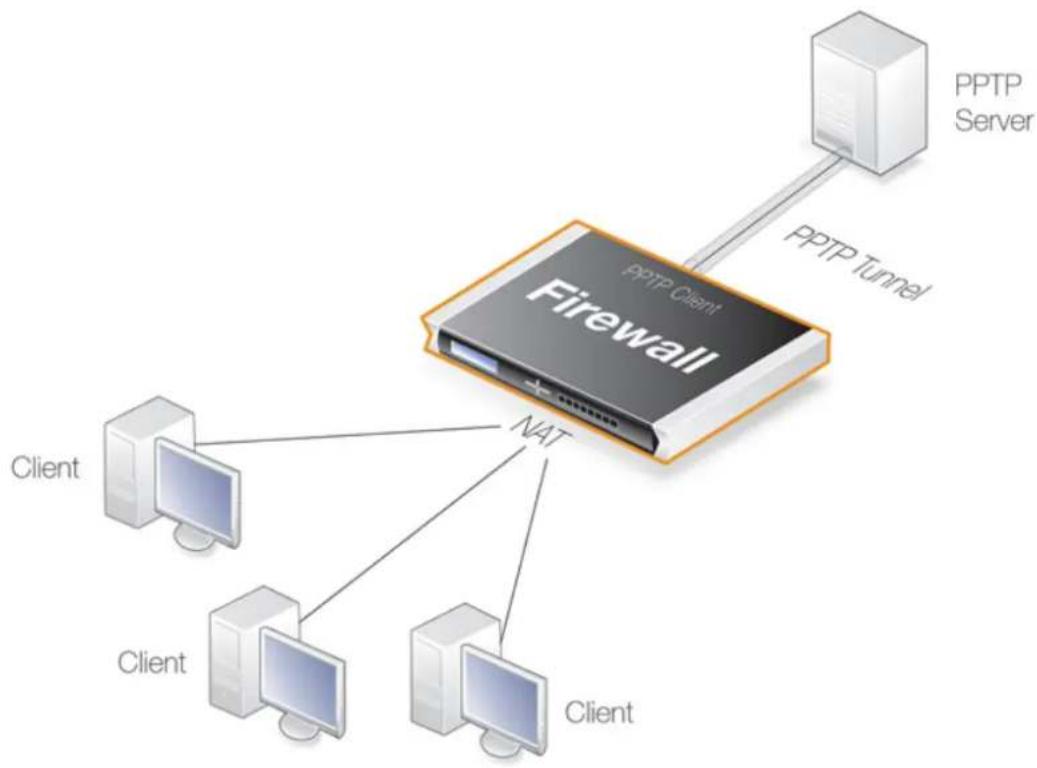
flowchart
graph TD
A["PPTP Server"] -->|PPTP Tunnel| B["Firewall"]
C["Client"] --> B
D["Client"] --> B
E["Client"] --> B
F["Client"] --> B
Figure 10.3. PPTP Client Usage
10.4.5. The l2tp and pptp Commands
NetDefendOS provides two CLI commands for monitoring the status of L2TP and PPP:
• The /2tp CLI Command
NetDefendOS provides the CLI command /2tp to show information about both L2TP clients and servers. To list the current state of all L2TP servers and clients, the command would be the following:
gw-world:/> 12tp -state=all
To view all the sessions for a specific L2TP server, the syntax would be:
gw-world:/> 12tp -l2tpserver=<L2TP-server-object-name>
Below is an example of some output where an L2TP tunnel object called my_l2tp_tunnel1 which has been established but has no connected clients so it is only listening.
gw-world:/> l2tp -state=all
Active and listening sessions
L2TP Tunnel Remote GW State Tunnel IDs
my_12tp_tunnel1 Listening 0 44555
If there are now two servers, one without clients (listening) and one with at least one client (established), the output might look like the following:
gw-world:/> 12tp -state=all
Active and listening sessions
L2TP Tunnel Remote GW State Tunnel IDs
my_12tp_tunnel1 Listening 0 44555
my_12tp_tunnel2 Listening 0 30859
my_12tp_tunnel2 203.0.113.1 Established 32008 39949
It is also possible to examine the child sessions open in a tunnel using the -child option. An example of this is shown below where a single session (#1) is active:
gw-world:/> l2tp -state=active -child
Active sessions
L2TP Tunnel Remote GW State Tunnel IDs
____
my_l2tp_tunnel1 203.0.113.1 Established 32008 39949
#1 - Established 1 1
• The pptp CLI Command
NetDefendOS provides the CLI command pptp to show information about both PPTP clients and servers. The pptp command syntax and output closely follows that of the l2tp command described above. For example, to list the current state of all PPTP servers and clients, the command would be the following:
gw-world:/> pptp -state=all
Active and listening sessions
PPTP Tunnel Remote GW State
my_pptp_tunnel1 Listening
my_pptp_tunnel1 203.0.113.6 Established
Both these commands and their options are fully described in the separate NetDefendOS CLI Reference Guide. Neither of these commands currently have an equivalent function in the Web Interface.
10.5. L2TP Version 3
L2TP Version 3 (L2TPv3) is a tunneling protocol that is an alternative to standard L2TP (standard L2TP is also referred to as L2TPv2). L2TPv2 can only tunnel PPP traffic, whereas L2TPv3 has the key advantage of emulating the properties of an OSI layer 2 service. This is sometimes referred to as Layer 2 Tunneling or as a pseudowire. This means L2TPv3 can carry Ethernet frames over an IP network, allowing one or more Ethernet LANs to be joined together across the Internet. NetDefendOS L2TPv3 can tunnel both Ethernet as well as VLANs.

Note: HA clusters do not support L2TPv3
NetDefendOS high availability clusters do not support L2TPv3. It should not be configured in an HA cluster.
Here is a summary of other advantages of L2TPv3 over L2TPv2:
- Can be carried directly over IP without UDP. L2TPv2 requires UDP.
• Better security against man-in-the-middle or packet-insertion attacks.
• Support for many more tunnels or many more sessions within one tunnel. - Can be manually configured with static parameters and does not require a control channel.
Other important considerations with L2TPv3 are:
- Like standard L2TP, L2TPv3 does not provide encryption of transmitted data. If the L2TPv3 tunnel is to be secure, it should be used with IPsec or PPPoE.
- L2TPv3 support in NetDefendOS allows the D-Link firewall to act as either an L2TPv3 server or a client. Setting up these two functions is described next.
- NetDefendOS L2TPv3 can only be used with IPv4. IPv6 is not supported by NetDefendOS at this time. However, IPv6 can be allowed to be transmitted, as described next.
Passthrough Settings
Both the NetDefendOS L2TPv3 client and server objects have two pass through properties associated with them:
- DHCP Passthrough
This allows DHCP protocol traffic to flow.
• Non-IP Protocol Passthrough
This allows non-IPv4 protocol traffic to flow. IPv6 traffic is an example of traffic which will be allowed when this property is enabled. However, the IPv6 traffic will not be subject to any configuration rules or policies.
It should note that these properties are disabled by default and when enabled, the traffic that they allow to flow will not be subject to any rules or policies in the NetDefendOS configuration.
10.5.1. L2TPv3 Server
When the D-Link firewall acts as an L2TPv3 server this means it allows connection of L2TPv3 clients so that networks on either side of the client and server can appear transparently connected to each other.
The steps for setup are described below. First, setup for non-VLAN scenarios are described and then setup for VLAN scenarios.
Setting Up a Standard L2TPv3 Server
Standard L2TPv3 setup for packets without VLAN tags requires the following:
A. Define an L2TPv3 Server object.
The object will require the following properties to be set:
i. Local Network - Set this to the protected network that will be accessed through the tunnel.
ii. Inner IP Address - Set this to any IPv4 address within the network used for the Local Network property. As a convention, it is recommended to use the IPv4 address of the physical interface connected to the protected network.
iii. Outer Interface Filter - Set this to be the listening interface for L2TPv3 client connections. Without IPsec, this is set to a physical Ethernet interface. When using IPsec for encryption, this is set to the IPsec tunnel object.
iv. Server IP - Set this to be the IP address of the listening interface.
B. Enable transparent mode for the protected interface.
Change the properties of the Ethernet interface connected to the protected network so that Transparent Mode is enabled.
C. Set any required L2TPv3 Server advanced options.
Some L2TPv3 clients may require the setting of the option Host Name or Router ID for the server object. If the Host Name is set to None, the tunnel's Inner IP Address is used for this setting.
The illustration below shows a typical setup for L2TPv3 where the protected network on interface If3 can be accessed by L2TPv3 clients connecting to the L2TPv3 server listening on the interface If2.
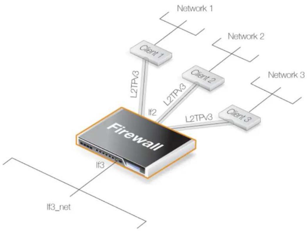
flowchart
graph TD
Firewall["Firewall"] --> Client1["Client 1"]
Firewall --> Client2["Client 2"]
Firewall --> Client3["Client 3"]
Firewall --> L2TPV3a["L2TPV3"]
Firewall --> L2TPV3b["If2"]
Firewall --> L2TPV3c["If3"]
Firewall --> L2TPV3d["If3_net"]
L2TPV3a --> Network1["Network 1"]
L2TPV3b --> Network2["Network 2"]
L2TPV3c --> Network3["Network 3"]
Figure 10.4. An L2TPv3 Example
Setting up the above scenario is covered in the example below.
Example 10.20. L2TPv3 Server Setup
Assume an L2TPv3 Server object called my_l2tpv3_if is to be set up so that L2TPv3 clients can connect to it on the If2 interface. The aim is to have the protected network If3_net on the If3 interface accessible to these clients using L2TPv3.
Command-Line Interface
A. First, define the L2TPv3 Server object:
gw-world:/> add Interface L2TPv3Server my_l2tpv3_if
IP=If3_ip
LocalNetwork=If3_net
Interface=If2
ServerIP=If2_ip
B. Next, enable transparent mode on the protected interface If3:
gw-world:/> set Interface Ethernet If3 AutoSwitchRoute=Yes
Web Interface
A. First, define an L2TPv3 Server object:
-
Go to: Network > Interfaces and VPN > L2TPv3 Servers > Add > L2TPv3 Server
-
Now enter:
-
Name: my_l2tpv3_if
- Inner IP Address: If3_ip
- Local Network: If3_net
- Outer Interface Filter: If2
-
Server IP: If2_ip
-
Click OK
B. Next, enable transparent mode on the protected interface If3:
- Go to: Network > Interfaces and VPN > Ethernet
- Select the If3 interface
- Select the option Enable transparent mode
- Click OK
The Protocol Property
The L2TPv3 Server configuration object has a Protocol property which defines the transport method for L2TPv3 communication at a lower protocol level. There are two options available:
• UDP
Using UDP as the lower level transport protocol is the default setting for this property and is recommended. It ensures that communication is able to traverse most network equipment and particularly if NAT is being employed in the path through network.
• IP
Using IP as the transport protocol allows packet processing to be optimized and therefore provides a means to transport data using less processing resources. However, some network equipment may not allow traversal and problems can occur where NAT is employed in the path through the network. Such problems can be solved by using UDP instead.
Using IPsec for Encryption
As with standard L2TP (L2TPv2), L2TPv3 does not provide encryption. To make communication secure, L2TPv3 should be therefore set up in conjunction with an IPsec Tunnel object and the listening interface then becomes the tunnel.
The setup of the IPsec tunnel follows the same procedure as for standard L2TP and this is described in Section 10.4.2, "L2TP Servers".
Example 10.21. L2TPv3 Server Setup With IPsec
Assume the same scenario as the previous example, but this time the L2TPv3 tunnel is itself being tunneled through an IPsec Tunnel object called my_ipsec_tunnel.
Setup of the IPsec tunnel is not shown in this example but follows the same setup described in Section 10.4.2, "L2TP Servers".
Command-Line Interface
A. First, define the L2TPv3 Server object:
gw-world:/> add Interface L2TPv3Server my_l2tpv3_if
IP=If3_ip
LocalNetwork=If3_net
Interface=my_ipsec_tunnel
ServerIP=If2_ip
B. Next, enable transparent mode on the protected interface If3:
gw-world:/> Set Interface Ethernet If3 AutoSwitchRoute=Yes
Web Interface
A. First, define an L2TPv3 Server object:
-
Go to: Network > Interfaces and VPN > L2TPv3 Servers > Add > L2TPv3 Server
-
Now enter:
-
Name: my_l2tpv3_if
- Inner IP Address: If3_ip
- Local Network: If3_net
- Outer Interface Filter: my_ipsec_tunnel
-
Server IP: If2_ip
-
Click OK
B. Next, enable transparent mode on the protected interface If3:
- Go to: Network > Interfaces and VPN > Ethernet
- Select the If3 interface
- Select the option Enable transparent mode
- Click OK
The NetDefendOS L2TPv3 server can handle VLAN tagged Ethernet frames so that a protected internal network can be accessed by external clients over VLAN connections.
To do this with NetDefendOS, a pair of VLANs need to be configured, both with the same VLAN ID as the ID used by the clients. One VLAN is configured on the local, protected Ethernet interface. The other VLAN is configured on the L2TPv3 server interface. Both of these VLANs must have transparent mode enabled. In addition, a new routing table must be defined for each pair and each VLAN in the pair is made a member of that table.
Here is a summary of the setup steps for VLAN:
A. Define an L2TPv3 server interface object as described previously but do not enable transparent mode on the protected Ethernet interface.
B. Set up a NetDefendOS VLAN interface object with the following properties:
i. The VLAN ID is the same as the VLAN ID of packets sent by clients.
ii. The interface is the protected Ethernet interface.
iii. The network is the same as the protected local network.
iv. The IPv4 address for the VLAN is any arbitrary IP from the protected local network.
v. Transparent mode for this VLAN is enabled.
C. Set up a second VLAN interface object with the following properties:
i. The VLAN ID is the same as the previous VLAN and the same as the ID of packets sent by clients.
ii. The interface is the L2TPv3 Server object defined previously.
iii. The network is the same as the protected local network.
iv. The IPv4 address for the VLAN is any arbitrary IP from the protected local network but different from the previous VLAN.
v. Transparent mode for this VLAN is enabled.
D. Define a new RoutingTable object for the pair.
E. Make each VLAN a member of this new routing table.
Example 10.22. L2TPv3 Server Setup For VLANs
Assume an L2TPv3 tunnel called my_l2tpv3_if is to be set up so that L2TPv3 clients can connect on the If2. The protected network If3_net on the If3 interface will be accessible to these clients.
In addition, the clients will access over a VLAN within the tunnel that has a VLAN ID of 555.
It is assumed two arbitrary IPv4 addresses called If3_arbitrary_ip1 and If3_arbitrary_ip2 from the protected network If3_net have already been defined in the NetDefendOS address book.
Command-Line Interface
A. First, define a L2TPv3 Server object:
gw-world:/> add Interface L2TPv3Server my_12tpv3_if
IP=If3_ip
LocalNetwork=If3
Interface=If2
ServerIP=If2_ip
B. Next, create a VLAN object on the protected interface If3:
gw-world:/> add Interface VLAN my_vlan_local
Ethernet=If3
VLANID=555
IP=If3_arbitrary_ip1
Network=If3_net
AutoSwitchRoute=Yes
C. Last, create a VLAN object on the L2TPv3 tunnel interface my_l2tpv3_if:
gw-world:/> add Interface VLAN my_vlan_12tpv3
Ethernet=my_12tpv3_if
VLANID=555
IP=If3_arbitrary_ip2
Network=If3_net
AutoSwitchRoute=Yes
D. Define a new RoutingTable object for this VLAN pair:
gw-world:/> add RoutingTable my_vlan_rt
E. Make each VLAN in the pair a member of this new routing table:
gw-world:/> set Interface VLAN my_vlan_local
MemberOfRoutingTable=Specific
RoutingTable=my_vlan_rt
gw-world:/> set Interface VLAN my_vlan_12tpv3
MemberOfRoutingTable=Specific
RoutingTable=my_vlan_rt
Web Interface
A. First, define a L2TPv3 Server object:
-
Go to: Network > Interfaces and VPN > L2TPv3 Servers > Add > L2TPv3 Server
-
Now enter:
-
Name: my_l2tpv3_if
- Inner IP Address: If3_ip
- Local Network: If3_net
- Outer Interface Filter: If2
-
Server IP: If2_ip
-
Click OK
B. Next, create a VLAN object on the protected interface If3:
-
Go to: Network > Interfaces and VPN > VLAN > Add > VLAN
-
Select the If3 interface
-
Now enter:
- Name: my_vlan_local
- Interface: If3
• VLAN ID: 555
- IP Address: If3_arbitrary_ip1
- Network: If3_net
-
Select the option Enable transparent mode
-
Click OK
C. Create a VLAN object on the L2TPv3 tunnel interface my_l2tpv3_if:
-
Go to: Network > Interfaces and VPN > VLAN > Add > VLAN
-
Select the If3 interface
-
Now enter:
- Name: my_vlan_l2tpv3
- Interface: my_l2tpv3_if
• VLAN ID: 555
- IP Address: If3_arbitrary_ip2
- Network: If3_net
-
Select the option Enable transparent mode
-
Click OK
D. Define a new RoutingTable object for this VLAN pair:
-
Go to: Network > Routing > Routing Tables > Add > Routing Table
-
For Name enter my_vlan_rt
-
Click OK
E. Make each VLAN in the pair a member of this new routing table:
-
Go to: Network > Interfaces and VPN > VLAN
-
Select my_vlan_local and edit the object:
- Go to Virtual Routing
- Select Make interface a member of a specific routing table
• For the Routing Table select my_vlan_rt
- Click OK
-
Select my_vlan_12tpv3 and edit the object:
-
Go to Virtual Routing
- Select Make interface a member of a specific routing table
• For the Routing Table select my_vlan_rt - Click OK
10.5.2. L2TPv3 Client
A D-Link firewall can also act as an L2TPv3 client. This allows a remote firewall configured as an L2TPv3 client to act as a concentrator of traffic from locally connected clients so it is sent through a single L2TPv3 tunnel to an L2TPv3 server.
The following steps are required to configure NetDefendOS to be an L2TPv3 client:
A. Define an L2TPv3Client object with the following properties:
i. Inner IP Address - The local IP address inside the tunnel. This is usually the IP address of the physical interface which is the local tunnel endpoint
ii. Local Network - The protected local network accessible through the tunnel.
iii. Pseudowire Type - This will normally be Ethernet. Set to VLAN for VLANs
iv. Protocol - This will normally be UDP.
v. Remote Endpoint - The IP address of the server.
B. Enable transparent mode on the inner interface where the protected network is located.
Example 10.23. L2TPv3 Client Setup
In this example, an L2TPv3 Client object called my_l2tpv3_client is to be created. This will connect with the L2TPv3 server with the IP address l2tpv3_server_ip.
This client will connect to the server over an IPsec tunnel called l2tpv3_ipsec_tunnel. It is assumed that the tunnel has already been defined.
Command-Line Interface
A. First, define the L2TPv3Client object:
gw-world:/> add Interface L2TPv3Client my_12tpv3_client
IP=inner_client_ip
LocalNetwork=If1_net
PseudowireType=Ethernet
Protocol=UDP
RemoteEndpoint=12tpv3_server_ip
B. Next, enable transparent mode on the protected interface If1:
gw-world:/> set Interface Ethernet If1 AutoSwitchRoute=Yes
Web Interface
A. First, define an L2TPv3 Client object:
-
Go to: Network > Interfaces and VPN > L2TPv3 Client > Add > L2TPv3 Client
-
Now enter:
-
Name: my_l2tpv3_client
• Inner IP Address: inner_client_ip - Local Network: If1_net
- Pseudowire Type: Ethernet
- Protocol: UDP
-
Remote Endpoint: l2tpv3_server_ip
-
Click OK
B. Next, enable transparent mode on the protected interface If1:
- Go to: Network > Interfaces and VPN > Ethernet
- Select the If1 interface
- Select the option Enable transparent mode
- Click OK
Using IPsec for Encryption
As stated previously, L2TPv3 does not provide encryption. For encryption across the Internet, IPsec should be used. The following example shows how this is achieved by specifying the IPsec tunnel to be used as a property of the L2TPv3 client object.
Example 10.24. L2TPv3 Client Setup With IPsec
This example is the same as the previous example but uses an IPsec tunnel to the server for encryption. It is assumed that the IPsec tunnel object has already been defined with the name l2tpv3_ipsec_tunnel.
IPsec tunnel setup is not shown here but it will follow the exact same procedure for L2TP which is shown in Example 10.19, "Setting up an L2TP Tunnel Over IPsec".
Command-Line Interface
A. Define the L2TPv3Client object:
gw-world:/> add Interface L2TPv3Client my_12tpv3_client
IP=inner_client_ip
LocalNetwork=If1_net
PseudowireType=Ethernet
Protocol=UDP
RemoteEndpoint=12tpv3_server_ip
IPsecInterface=12tpv3_ipsec_tunnel
B. Next, enable transparent mode on the protected interface If1:
gw-world:/> set Interface Ethernet If1 AutoSwitchRoute=Yes
Web Interface
A. First, define an L2TPv3 Client object:
1. Go to: Network > Interfaces and VPN > L2TPv3 Client > Add > L2TPv3 Client
2. Now enter:
- Name: my_l2tpv3_client
• Inner IP Address: inner_client_ip - Local Network: If1_net
• Pseudowire Type: Ethernet - Protocol: UDP
- Remote Endpoint: l2tpv3_server_ip
-
IPsecInterface: l2tpv3_ipsec_tunnel
-
Click OK
B. Next, enable transparent mode on the protected interface If1:
- Go to: Network > Interfaces and VPN > Ethernet
- Select the If1 interface
-
Select the option Enable transparent mode
-
Click OK
Setup With VLANs
The NetDefendOS L2TPv3 client can handle VLAN tagged Ethernet frames so that a protected internal network can be access an external network over VLAN connections. The setup of the VLANs is done in the same way as for the server and this is fully described in Section 10.5.1, "L2TPv3 Server".
When setting up the L2TPv3 client object, the PseudowireType property must be set to the value VLAN.
10.6. SSL VPN
10.6.1. Overview
NetDefendOS provides an additional type of VPN connection called SSL VPN. This makes use of the Secure Sockets Layer (SSL) protocol to provide a secure tunnel between a remote client computer and a D-Link firewall. Any application on the client can then communicate securely with servers located on the protected side of the firewall.
The Advantage of SSL VPN
The key advantage of SSL VPN is that it enables secure communications between a client and a firewall using the HTTPS protocol. In some environments where roaming clients have to operate, such as hotels or airports, network equipment will often not allow other tunneling protocols, such as IPsec, to be used.
In such cases, SSL VPN provides a viable, simple, secure client connection solution.
The SSL VPN Disadvantage
A disadvantage of SSL VPN is that it relies on tunneling techniques that make extensive use of TCP protocol encapsulation for reliable transmission. This leads to extra processing overhead which can cause noticeable latencies in some high load situations.
SSL VPN therefore demands more processing resources than, for example, IPsec. In addition, hardware acceleration for IPsec is available on some hardware platforms to further boost processing efficiency.
Cryptographic Suites and TLS Version Supported by NetDefendOS
NetDefendOS supports a number of cryptographic algorithms for SSL VPN. Only some are enabled by default and all can be either enabled or disabled. All the supported algorithms are listed in Section 13.9, "SSL/TLS Settings". Note that TLS versions 1.0 and 1.2 are supported by NetDefendOS but not version 1.1. Refer to Section 13.9, "SSL/TLS Settings" for how to set the minimum version that is allowed.
By default, only the four algorithms which are considered the most secure are enabled. It is not recommended to enable the weaker algorithms and they exist primarily for backwards compatibility.
A Summary of SSL VPN Setup Steps
Setting up SSL VPN requires the following steps:
• On the D-Link firewall side:
i. An SSL VPN Interface object needs to be created which configures a particular Ethernet interface to accept SSL VPN connections.
ii. An Authentication Rule needs to be defined for incoming SSL VPN clients and the rule must have the Interface property set to be the name of the SSL VPN object created above.
The Authentication Agent of the rule must be set to L2TP/PPTP/SSL VPN and the rule's
Terminator IP must be set to the external IP address of the firewall's listening interface.
The PPP Agent Options for the rule should have only the PAP option enabled.
iii. If only a specific IP address, network or network range is to be made available to the client through the tunnel then this can be specified as an option on the SSL VPN interface. Otherwise, it is assumed that all client traffic will be routed through the tunnel.
iv. Client users need to be defined in the Authentication Source of the authentication rule. This source can be a local user database, a RADIUS server or an LDAP server.
v. Define appropriate NetDefendOS IP policies to allow data flow within the SSL VPN tunnel. As discussed below, IP policies do not normally need to be defined for the setup of the SSL VPN tunnel itself, they are only needed for the traffic that flows inside the tunnel.
vi. Specify the interfaces on which client IPs will be ARP published. This is necessary so a server behind the firewall knows how to send replies back to an SSL VPN client.
Usually, the only time proxy ARP needs to be enabled is if the IPs assigned to clients are part of an already existing subnet that clients need access to. In that case, proxy ARP must be enabled on the interface that has the corresponding subnet. If the traffic is routed by the firewall, for example with an Allow IP policy or a NAT IP policy proxy ARP is not needed.
The option exists with NetDefendOS SSL VPN to automatically ARP publish all client IPs on all firewall interfaces but this is not recommended because of the security issues that are raised.
vii. Routes for clients do not need to be defined in the routing tables as these are added automatically by NetDefendOS when SSL VPN tunnels are established.
The configuration of SSL VPN in NetDefendOS is described further in Section 10.6.2, "Configuring SSL VPN in NetDefendOS".
• On the Windows based client side:
A proprietary D-Link VPN SSL client application needs to be installed and configured to route traffic to the correct interface on the firewall.
Installing and running the SSL VPN client software is done as part of the logging in process for users as they access the firewall through a web browser. The Windows based client software is automatically downloaded through the browser directly from the firewall.
SSL VPN with PPPoE
Where PPPoE is used as the method of connection to the D-Link firewall over the Internet, it is possible to have SSL VPN function over the PPPoE connection.
This is done by setting up the SSL VPN tunnel so that the Outer Interface property of the SSL VPN tunnel object is specified to be a PPPoE configuration object instead of a physical Ethernet interface. Setting up a PPPoE interface object is described in Section 3.4.6, "PPPoE".
10.6.2. Configuring SSL VPN in NetDefendOS
To configure SSL VPN in NetDefendOS, an SSL VPN Interface object must be defined for each interface on which connections will be made. The object properties are as follows:
General Options
- Name
A descriptive name for the object used for display in the NetDefendOS configuration.
- Inner IP
This is the IP address within the tunnel that SSL VPN clients will connect to.
All clients that connect to the SSL VPN object interface are allocated an IP from the SSL VPN interface's IP Pool. All the pool addresses as well as the Inner IP must belong to the same network and these define the relationship between the firewall and the connecting clients.
A private IP network should be used for this purpose. The Inner IP itself must not be one of the IP Pool addresses that can be handed out to connecting SSL VPN clients.

Tip: The Inner IP can be pinged
For troubleshooting purposes, an ICMP Ping can be sent to the Inner IP address. In order for NetDefendOS to be able to respond, an IP policy must exist that allows traffic to flow from the SSL VPN interface to core (in other words, to NetDefendOS itself).
- Outer Interface
The interface on which to listen for SSL VPN connection attempts. This could be a physical Ethernet interface but it could also be another logical interface. For example, a PPPoE or VLAN interface could be used.
- Server IP
The Ethernet interface IP address on which to listen for SSL VPN connection attempts by clients. This will typically be a public IPv4 address which will be initially accessed using a web browser across the Internet. The following should be noted about this IP:
i. The Server IP must be specified and will not default to the IP of the Outer Interface.
ii. The Server IP cannot be an IP address which is ARP published on the interface. In order for SSL to work on ARP published IPs, a core route with an accompanying proxy ARP property must be used. This is done with the following steps:
- Define a route with the Interface property set to core and the Network property set to the Server IP value.
- Set the route's Proxy ARP property to the interfaces which clients are connecting to.
Proxy ARP is explained further in Section 4.2.6, "Proxy ARP".
- Server Port
The TCP/IP port number at the Server IP used in listening for SSL VPN connection attempts by clients. The default value is 443 which is the standard port number for SSL.
Client IP Options
• Dynamic Server Address
Instead of a fixed IP address for the SSL VPN Server IP being handed out to clients, this option
makes it possible to hand out a Fully Qualified Domain Name (FQDN) instead.
For example, the FQDN might be specified as server.example.com. When a client connects to the SSL VPN interface, this FQDN is handed out to the client which then resolves the FQDN using DNS to a specific IP address. This allows the server address to change dynamically with only the DNS entry being changed.
If this option is specified, the Server IP in General Options above is ignored.
• IP Pool
As described above, client IP addresses for new SSL VPN connections are handed out from a pool of private IPv4 addresses. This pool is specified by an IP address object defined in the NetDefendOS address book. It is not the same as an IP Pool object used with IPsec.
The pool addresses do not need to be a continuous range but must belong to the same network. The Inner IP property must also belong to this network but must not be one of the pool IPs.

Note: Pool addresses must not exceed a /24 network size
SSL VPN will not function correctly if an IP address is handed out that exceeds the size of a Class C subnet (a /24 network with netmask 255.255.255.0).
- Primary DNS
The primary DNS address handed out to a connecting client.
- Secondary DNS
The secondary DNS address handed out to a connecting client.
- Client Routes
By default, all client traffic is routed through the SSL tunnel when the client software is activated. This behavior can be changed by specifying that only specific IPv4 addresses, networks or address ranges will be accessible through the tunnel.
When this is done, only the specified routes through the tunnel are added to the client's routing table and all other traffic is routed as normal. A maximum of five custom routes can be specified for a tunnel.
Add Route Option
- Proxy ARP
So that SSL VPN clients can be found by a network connected to another Ethernet interface, client IP addresses need to be explicitly ARP published on that interface.
This Add Route option allows the interfaces for ARP publishing to be chosen. In most situations it will be necessary to choose at least one interface on which to publish the client network.
10.6.3. Installing the SSL VPN Client
For the SSL VPN to function, a proprietary D-Link SSL VPN client application must be installed on
the client computer. This is done with the following steps:
- A web browser must be opened and the protocol https://needs to be entered into the browser navigation field followed by the IP address or URL for the Ethernet interface on the firewall that is configured for SSL VPN.
The IP address will be the same as the Server IP configured in the interface's SSL VPN object. The port can also be specified after the IP address if it is different from the default value of 443.
With https, the firewall will send a certificate to the browser that is not CA signed and this must be accepted as an exception by the user before continuing.
-
NetDefendOS now displays a login dialog in the browser.
-
The credentials entered are checked against the user database. If the user is authenticated, a web page is displayed which offers two choices:
i. Download the D-Link SSL VPN client software
If this option has not been chosen before, it must be selected first to install the proprietary D-Link SSL VPN client application.
ii. Connect the SSL VPN client
If the client software is already installed, selecting this option starts the client running and an SSL VPN tunnel is established to the firewall. This is discussed next in more detail.
Using CA Signed Certificates
By default, NetDefendOS uses a self-signed certificate when it displays the dialog shown above. If it is desirable to use a CA signed certificate, that may or may not use certificate chaining, this can be configured on the RemoteMgmtSettings object. In other words, the certificates used for HTTPS Web Interface access are the same ones used for SSL VPN login. Configuring these certificates is explained further in Section 2.1.4, "The Web Interface".
Running the Client SSL VPN Software
An SSL VPN tunnel becomes established whenever the D-Link SSL VPN client application runs. Conversely, the tunnel is taken down when the application stops running.
There are two ways for the tunnel to be established:
- To login by using a web browser to surf to the SSL VPN interface as described above. Once the client software is installed, only the option to establish the tunnel is selected.
- Once the client software is installed, it can be started by selecting it in the Windows Start menu. The SSL VPN client user interface then opens, the user password is entered and when OK is pressed the tunnel is established and any client computer application can then make use of it.
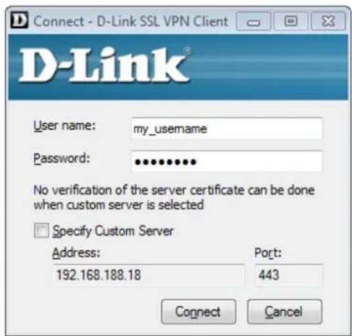
Figure 10.5. The SSL VPN Client Login
The difference between the two approaches above is that when the SSL VPN client software is started by browsing to the SSL VPN interface, the correct settings for the tunnel are downloaded to the SSL VPN client software and stored as the client's configuration file.
As long as these settings have not changed between tunnel sessions, it is possible to start the SSL VPN client software running by selecting it in the Start menu and connecting to the same SSL VPN interface. In particular, the SSL VPN client checks the certificate used by the SSL VPN interface by comparing a certificate fingerprint stored in the configuration file with a fingerprint sent by the interface.
The reason for checking the certificate in this way is that it solves the "man in the middle" problem where a malicious third party might try to intercept communications between the firewall and the client.
Custom Server Connection
When the SSL VPN client software is started, it is possible to connect to an SSL VPN interface on a D-Link firewall that has not been connected to before. This is done by enabling the option Specify Custom Server and explicitly specifying the IP address, port and login credentials for the server.
With the Specify Custom Server option enabled, the SSL VPN client ignores any configuration file parameters previously downloaded by an SSL VPN connection established using the web interface. In particular, it does not check the certificate used by the firewall.
The disadvantage of using the custom server option is that there is no certificate checking and the "man in the middle" problem remains.
Client Transfer Statistics
When the SSL VPN client is running, an icon for it will appear in the system tray. Clicking this icon will bring up the client's interface showing amounts of data transferred since tunnel setup.
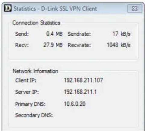
Figure 10.6. The SSL VPN Client Statistics
SSL VPN Client Operation
Whenever the SSL VPN client application runs, the following happens:
- A route is added to the Windows routing table. This route is equivalent to a NetDefendOS default all-nets route.
• The added default route directs all traffic from the Windows client through the SSL tunnel.
When the Windows SSL VPN client application ends, the SSL tunnel is closed and the default route in the Windows routing table is removed, returning the routing table to its original state.
- An SSL connection is made to the configured Ethernet interface on a D-Link firewall and the next available IP address is handed out to the client from the associated SSL VPN object's IP pool.
In addition, a single route for the client is added to the NetDefendOS routing table. This route maps the handed out client IP address to the associated SSL VPN interface.
- Traffic can now flow between the client and the firewall, subject to the configured IP rule set.
Specifying IP Policies for Traffic Flow
No IP policies need to be specified for the setup of an SSL VPN tunnel itself, provided that the advanced setting SSLVPNBeforeRules is enabled. However, appropriate IP policies need to be specified by the administrator to allow traffic to flow through the tunnel.
Since SSL VPN connections originate from the client side, the SSL VPN interface object should be the source interface of the IP policy and the source network should be the range of possible IP addresses that the clients can be given. Specifying the source network as all-nets would of course work but it always more secure to use the narrowest possible IP address range.
For more information about specifying IP policies see Section 3.6, "IP Rule Sets".
Client Cleanup
Should the SSL VPN client application terminate prematurely for some reason, the Windows routing table may not be left in a consistent state and the automatically added all-nets route may not have been removed.
To remedy this problem, the D-Link SSL VPN client software should be started by selecting it in the Windows Start menu and then stopped.
Manually Specifying the Client's Default Gateway
If the SSL VPN client's connection to the server is NATed, it is important that the client's route to the default gateway is not added manually in a Windows console using the "route add" command.
If the default gateway has been added in this way, the SSL VPN link will become established and function for a short time before the link stops working and the client gives the following error message: SSL stream closed unexpectedly. If the client console is then opened, it will show there was an error when reading from the SSL socket.
This problem is solved by not using the Windows console to manually add the default gateway route. Instead, do this through the Windows Control Panel or allow the SSL VPN client software to add the route automatically.
10.6.4. SSL VPN Setup Example
Example 10.25. Setting Up an SSL VPN Interface
This example shows how to set up a new SSL VPN interface called my_sslvpn_if.
Assume that the physical interface If2 is used to listen for client connections and this has an external IP address already defined in the address book called sslvpn_server_ip. Connections will be made using SSL VPN to a server located on the network connected to the firewall's If3 Ethernet interface.
Assume also that the IPv4 addresses that will be handed out to clients are defined by the address book object sslvpn_pool. For this example, this contains the simple address range 10.0.0.2-10.0.0.9.
Another address book IP object sslvpn_inner_ip is defined to be 10.0.0.1 and this will be the inner IP of the NetDefendOS end of the tunnel.
1. Create an SSL VPN Object
Command-Line Interface
gw-world:/> add Interface SSLVPNInterface my_sslvpn_if
InnerIP=sslvpn_inner_ip
IPAddressPool=sslvpn_pool
OuterInterface=If2
ServerIP=sslvpn_server_ip
ProxyARPInterfaces=If3
Note: If multiple Proxy ARP interfaces are needed, they are specified as a comma separated list. For example: If3, If4, If5.
Web Interface
-
Go to: Network > Interfaces and VPN > SSL > Add > SSL VPN Interface
-
Now enter:
-
Specify a suitable name, in this example my_sslvpn_if
- Inner IP: sslvpn_inner_ip
- Outer Interface: If2
- Server IP: sslvpn_server_ip
-
IP Pool: sslvpn_pool
-
Click the tab Add Route
-
Select the If3 interface in the Available list and press the ">>" button to move it into the Selected list
-
Click OK
2. Create an Authentication Rule
Command-Line Interface
gw-world:/> add UserAuthRule Name=ssl_login
Interface=my_sslvpn_if
AuthSource=Local
LocalUserDB=lannet_auth_users
OriginatorIP=all-nets
Agent=PPP
TerminatorIP=sslvpn_server_ip
Web Interface
-
Go to: Policies > User Authentication User Authentication Rules > Add > User Authentication Rule
-
Now enter:
-
Name: ssl_login
• Agent: L2TP/PPTP/SSL VPN
• Authentication Source: Local - Interface: my_sslvpn_if
• Originator IP: all-nets (a more specific range is more secure) -
Terminator IP: sslvpn_server_ip
-
For Local User DB choose lannet_auth_users.
-
For Login Type choose HTMLForm
-
Click OK
The new NetDefendOS configuration should now be deployed.
For external client connection, a web browser should be directed to the IP address my_sslvpn_if. This is done either by typing the actual IP address or using a URL that can resolve to the IP address.
Example 10.26. Setting SSL VPN Interface Client Routes
This example shows how to change the SSL VPN tunnel called my_sslvpn_if so that the only route added to the routing table of clients is a route to the protected network protected_server_net which is already defined in the NetDefendOS address book.
Command-Line Interface
gw-world:/> set Interface SSLVPNInterface my_sslvpn_if ClientRoutes=protected_server_net
Web Interface
- Go to: Network > Interfaces and VPN > SSL
- Select the tunnel called my_sslvpn_if
- Under Client Routes move the address object protected_server_net from Available to Selected.
- Click OK
Chapter 11: Traffic Management
This chapter describes how NetDefendOS can manage network traffic.
• Traffic Shaping, page 897
• IDP Traffic Shaping, page 919
• Server Load Balancing, page 924
11.1. Traffic Shaping
11.1.1. Overview
QoS with TCP/IP
A weakness of TCP/IP is the lack of true Quality of Service (QoS) functionality. QoS is the ability to guarantee and limit network bandwidth for certain services and users. Solutions such as the Differentiated Services (DiffServ) architecture have been designed to try and deal with the QoS issue in large networks by using information in packet headers to provide network devices with QoS information.
NetDefendOS DiffServ Support
NetDefendOS supports the DiffServ architecture in the following ways:
- NetDefendOS forwards the 6 bits which make up the DiffServ Differentiated Services Code Point (DSCP).
- As described later in this chapter, DSCP bits can be used by the NetDefendOS traffic shaping subsystem as a basis for prioritizing traffic passing through the D-Link firewall.
It is important to understand that NetDefendOS traffic shaping does not add new DiffServ information as packets traverse a D-Link firewall. The NetDefendOS traffic shaping priorities described later in this chapter are for traffic shaping within NetDefendOS only and are not translated into DiffServ information that is then added to packets.
The Traffic Shaping Solution
However, architectures like DiffServ fall short if applications themselves supply the network with QoS information. In most networks it is rarely appropriate to let the applications, the users of the network, decide the priority of their own traffic. If the users cannot be relied upon then the network equipment must make the decisions concerning priorities and bandwidth allocation.
NetDefendOS provides QoS control by allowing the administrator to apply limits and guarantees to the network traffic passing through the D-Link firewall. This approach is often referred to as traffic shaping and is well suited to managing bandwidth for local area networks as well as to managing the bottlenecks that might be found in larger wide area networks. It can be applied to any traffic including that passing through VPN tunnels.
Traffic Shaping Objectives
Traffic shaping operates by measuring and queuing IP packets with respect to a number of configurable parameters. The objectives are:
- Applying bandwidth limits and queuing packets that exceed configured limits, then sending them later when bandwidth demands are lower.
- Dropping packets if packet buffers are full. The packets to be dropped should be chosen from those that are responsible for the congestion.
- Prioritizing traffic according to administrator decisions. If traffic with a high priority increases while a communication line is full, traffic with a low priority can be temporarily limited to make room for the higher priority traffic.
- Providing bandwidth guarantees. This is typically accomplished by treating a certain amount of traffic (the guaranteed amount) as high priority. The traffic that is in excess of the guarantee then has the same priority as other traffic, competing with all the other non-prioritized traffic.
Traffic shaping does not typically work by queuing up immense amounts of data and then sorting out the prioritized traffic to send before sending non-prioritized traffic. Instead, the amount of prioritized traffic is measured and the non-prioritized traffic is limited dynamically so that it will not interfere with the throughput of prioritized traffic.

Note: Traffic shaping will not work with the SIP ALG
Any traffic connection that triggers an IP policy that uses the SIP ALG cannot also be subject to traffic shaping.
11.1.2. Traffic Shaping in NetDefendOS
NetDefendOS offers extensive traffic shaping capabilities for the packets passing through the D-Link firewall. Different rate limits and traffic guarantees can be created as policies based on a filter that specifies the traffic's source, destination and protocol. This filter is similar to the filter used for IP rule set entries.
The two key components for traffic shaping in NetDefendOS are:
• Pipes
- Pipe Rules
Pipes
A Pipe is the fundamental object for traffic shaping and is a conceptual channel through which data traffic can flow. It has various characteristics that define how traffic passing through it is handled. As many pipes as are required can be defined by the administrator. None are defined by default.
Pipes are simplistic in that they do not care about the types of traffic that pass through them nor the direction of that traffic. They simply measure the aggregate data that passes through them and then apply the administrator configured limits for the pipe as a whole or for Precedences and/or Groups (these concepts are explained later in Section 11.1.6, "Precedences").
NetDefendOS is capable of handling hundreds of pipes simultaneously, but in reality most scenarios require only a handful of pipes. It is possible that dozens of pipes might be needed in scenarios where individual pipes are used for individual protocols. Large numbers of pipes might also be needed in an ISP scenario where individual pipes are allocated to each client.
Pipe Rules
One or more Pipe Rules make up the NetDefendOS Pipe Rule set which determine what traffic will flow through which pipes. Each pipe rule is defined like other NetDefendOS security policies: by specifying both the source/destination and interface/network for which the rule is to trigger, as well as the service.

Caution: Avoid using "any" as the source interface
The filtering criteria in a pipe rule should be as specific as possible and should ideally trigger on specific interfaces and networks. In particular, avoid using any as the source interface. In certain cases, this could result in traffic shaping being applied to the same traffic twice.
Once a new connection is permitted by the IP rule set, the pipe rule set is then checked for any matching pipe rules. Pipe rules are checked in the same way as other rule sets, by scanning entries from top to bottom (first to last). The first matching rule, if any, decides if the connection is subject to traffic shaping. Keep in mind that any connection that does not trigger a pipe rule will not be subject to traffic shaping and could potentially use as much bandwidth as it wants.
The rule set for pipe rules is initially empty with no rules predefined. At least one rule must be created for traffic shaping to begin to function.
Pipe Rule Chains
When a pipe rule is defined, the pipes to be used with that rule are also specified and they are placed into one of two lists in the pipe rule. These lists are:
• The Forward Chain
These are the pipe or pipes that will be used for outgoing (leaving) traffic from the firewall. One, none or a series of pipes may be specified.
• The Return Chain
These are the pipe or pipes that will be used for incoming (arriving) traffic. One, none or a series of pipes may be specified.
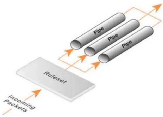
flowchart
graph TD
A["Incoming Packets"] --> B["Ruleset"]
B --> C["Pipe"]
B --> D["Pipe"]
B --> E["Pipe"]
C --> F["-->"]
D --> F
E --> F
style A fill:#f9f,stroke:#333
style B fill:#ccc,stroke:#333
style C fill:#fff,stroke:#333
style D fill:#fff,stroke:#333
style E fill:#fff,stroke:#333
style F fill:#fff,stroke:#333
Figure 11.1. Pipe Rules Determine Pipe Usage
The pipes that are to be used are specified in a pipe list. If only one pipe is specified then that is the pipe whose characteristics will be applied to the traffic. If a series of pipes are specified then these will form a Chain of pipes through which traffic will pass. A chain can be made up of a maximum of 8 pipes.
Explicitly Excluding Traffic from Shaping
If no pipe is specified in a pipe rule list then traffic that triggers the rule will not flow through any pipe. It also means that the triggering traffic will not be subject to any other matching pipe rules that might be found later in the rule set.
This provides a means to explicitly exclude particular traffic from traffic shaping. Such rules are not absolutely necessary but if placed at the beginning of the pipe rule set, they can guard against accidental traffic shaping by later rules.
Pipes Will Not Work With Stateless Policy Rules
It is important to understand that traffic shaping will not work with traffic that flows as a result of triggering a Stateless Policy entry in the IP rule set. (With an IP Rule, this is known as a FwdFast rule.)
The reason for this is that traffic shaping is implemented by using the NetDefendOS state engine which is the subsystem that deals with the tracking of connections. A Stateless Policy does not set up a connection in the state engine. Instead, packets are considered not to be part of a connection and are forwarded individually to their destination, bypassing the state engine.
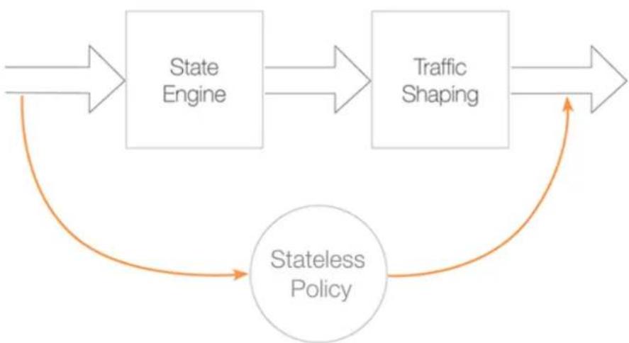
flowchart
graph TD
A["State Engine"] --> B["Traffic Shaping"]
B --> C["Stateless Policy"]
C --> A
Figure 11.2. A Stateless Policy Bypasses Traffic Shaping
Using Pipes with Application Control
When using the Application Control feature, it is possible to associate a pipe object directly with an Application Rule object in order to define a bandwidth for a particular application. For example, the bandwidth allocated to the BitTorrent peer-to-peer application could be limited in this way.
This feature is discussed further in Section 3.7, "Application Control".
11.1.3. Simple Bandwidth Limiting
The simplest use of pipes is for bandwidth limiting. This is also a scenario that does not require much planning. The example that follows applies a bandwidth limit to inbound traffic only. This is the direction most likely to cause problems for Internet connections.
Example 11.1. Applying a Simple Bandwidth Limit
Begin with creating a simple pipe that limits all traffic that gets passed through it to 2 megabits per second, regardless of what traffic it is.
Command-Line Interface
gw-world:/> add Pipe std-in LimitKbpsTotal=2000
Web Interface
- Go to: Policies > Traffic Management > Pipes > Add > Pipe
- Specify a suitable name for the pipe, for instance std-in
- Enter 2000 in the Total textbox under Pipe Limits
- Click OK
Traffic needs to be passed through the pipe and this is done by using the pipe in a Pipe Rule.
We will use the above pipe to limit inbound traffic. This limit will apply to the actual data packets, and not the connections. In traffic shaping we're interested in the direction that data is being shuffled, not which computer initiated the connection.
Create a simple rule that allows everything from the inside, going out. We add the pipe that we created to the return chain. This means that the packets travelling in the return direction of this connection (outside-in) should pass through the std-in pipe.
Command-Line Interface
gw-world:/> add PipeRule SourceInterface=lan
SourceNetwork=lannet
DestinationInterface=wan
DestinationNetwork=all-nets
Service=all_services
ReturnChain=std-in
Name=Outbound
Web Interface
- Go to: Traffic Management > Traffic Shaping > Add > Pipe Rule
- Specify a suitable name for the pipe, for instance outbound
- Now enter:
• Service: all_services
- Source Interface: Ian
- Source Network: Iannet
- Destination Interface: wan
- Destination Network: all-nets
-
Under the Traffic Shaping tab, make std-in selected in the Return Chain control
-
Click OK
This setup limits all traffic from the outside (the Internet) to 2 megabits per second. No priorities are applied, and neither is any dynamic balancing.
11.1.4. Limiting Bandwidth in Both Directions
Using a Single Pipe for Both Directions
A single pipe does not care in which direction the traffic through it is flowing when it calculates total throughout. Using the same pipe for both outbound and inbound traffic is allowed by NetDefendOS but this will not partition the pipe limit exactly in two between the two directions.
In the previous example only bandwidth in the inbound direction is limited. In most situations, this is the direction that becomes full first. But what if the outbound traffic must be limited in the same way?
Just inserting std-in in the forward chain will not work since we probably want the 2 Mbps limit for outbound traffic to be separate from the 2 Mbps limit for inbound traffic. If 2 Mbps of outbound traffic attempts to flow through the pipe in addition to 2 Mbps of inbound traffic, the total attempting to flow is 4 Mbps. Since the pipe limit is 2 Mbps, the actual flow will be close to 1 Mbps in each direction.
Raising the total pipe limit to 4 Mbps will not solve the problem since the single pipe will not know that 2 Mbps of inbound and 2 Mbps of outbound are the intended limits. The result might be 3 Mbps outbound and 1 Mbps inbound since this also adds up to 4 Mbps.
Using Two Separate Pipes Instead
The recommended way to control bandwidth in both directions is to use two separate pipes, one for inbound and one for outbound traffic. In the scenario under discussion each pipe would have a 2 Mbps limit to achieve the desired result. The following example goes through the setup for this.
Example 11.2. Limiting Bandwidth in Both Directions
Create a second pipe for outbound traffic:
Command-Line Interface
gw-world:/> add Pipe std-out LimitKbpsTotal=2000
Web Interface
- Go to: Policies > Traffic Management > Pipes > Add > Pipe
- Specify a name for the pipe, for example std-out
- Enter 2000 in Total textbox
- Click OK
After creating a pipe for outbound bandwidth control, add it to the forward pipe chain of the rule created in the previous example:
Command-Line Interface
gw-world:/> set PipeRule Outbound ForwardChain=std-out
Web Interface
- Go to: Traffic Management > Traffic Shaping > Pipe Rules
- Right-click on the pipe rule that was created in the previous example and choose Edit
- Under the Traffic Shaping tab, select std-out in the Forward Chain list
- Click OK
This results in all outbound connections being limited to 2 Mbps in each direction.
11.1.5. Creating Differentiated Limits Using Chains
In the previous examples a static traffic limit for all outbound connections was applied. What if the aim is to limit web surfing more than other traffic? Assume that the total bandwidth limit is 250 Kbps and 125 Kbps of that is to be allocated to web surfing inbound traffic.
The Incorrect Solution
Two "surfing" pipes for inbound and outbound traffic could be set up. However, it is not usually required to limit outbound traffic since most web surfing usually consists of short outbound server requests followed by long inbound responses.
A surf-in pipe is therefore first created for inbound traffic with a 125 Kbps limit. Next, a new Pipe Rule is set up for surfing that uses the surf-in pipe and it is placed before the rule that directs everything else through the std-in pipe. That way web surfing traffic goes through the surf-in pipe and everything else is handled by the rule and pipe created earlier.
Unfortunately this will not achieve the desired effect, which is allocating a maximum of 125 Kbps to inbound surfing traffic as part of the 250 Kbps total. Inbound traffic will pass through one of two pipes: one that allows 250 Kbps, and one that allows 125 Kbps, giving a possible total of 375 Kbps of inbound traffic but this exceeds the real limit of 250 Kbps.
The Correct Solution
To provide the solution, create a chain of the surf-in pipe followed by the std-in pipe in the pipe rule for surfing traffic. Inbound surfing traffic will now first pass through surf-in and be limited to a maximum of 125 Kbps. Then, it will pass through the std-in pipe along with other inbound traffic, which will apply the 250 Kbps total limit.
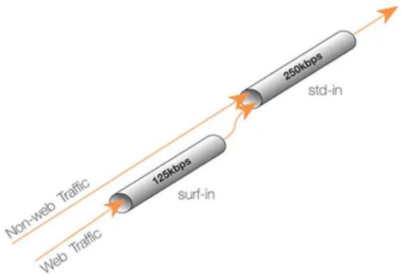
Figure 11.3. Differentiated Limits Using Chains
If surfing uses the full limit of 125 Kbps, those 125 Kbps will occupy half of the std-in pipe leaving 125 Kbps for the rest of the traffic. If no surfing is taking place then all of the 250 Kbps allowed through std-in will be available for other traffic.
This does not provide a bandwidth guarantee for web browsing but instead limits it to 125 Kbps
and provides a 125 Kbps guarantee for everything else. For web browsing the normal rules of first-come, first-forwarded will apply when competing for the 125 Kbps bandwidth. This may mean 125 Kbps, but it may also mean much slower speed if the connection is flooded.
Setting up pipes in this way only puts limits on the maximum values for certain traffic types. It does not give priorities to different types of competing traffic.
11.1.6. Precedences
The Default Precedence is Zero
All packets that pass through NetDefendOS traffic shaping pipes have a Precedence. In the examples so far, precedences have not been explicitly set and so all packets have had the same default precedence which is 0.
There are 8 Possible Precedence Levels
Eight precedences exist which are numbered from 0 to 7. Precedence 0 is the least important (lowest priority) precedence and 7 is the most important (highest priority) precedence. A precedence can be viewed as a separate traffic queue; traffic in precedence 2 will be forwarded before traffic in precedence 0, precedence 4 forwarded before 2.

Figure 11.4. The Eight Pipe Precedences
Precedence Priority is Relative
The priority of a precedence comes from the fact that it is either higher or lower than another precedence and not from the number itself. For example, if two precedences are used in a traffic shaping scenario, choosing precedences 4 and 6 instead of 0 and 3 will make no difference to the end result.
Allocating Precedence to Traffic
The way precedence is assigned to traffic is specified in the triggering pipe rule and can be done in one of three ways:
• Use the precedence of the first pipe
Each pipe has a Default Precedence and packets take the default precedence of the first pipe they pass through.
- Use a fixed precedence
The triggering pipe rule explicitly allocates a fixed precedence.
- Use the DSCP bits
Take the precedence from the DSCP bits in the packet. DSCP is a subset of the DiffServ architecture where the Type of Service (ToS) bits are included in the IP packet header.
Specifying Precedences Within Pipes
When a pipe is configured, a Default Precedence, a Minimum Precedence and a Maximum Precedence can be specified. The default precedences are:
• Minimum Precedence: 0
- Default Precedence: 0
• Maximum Precedence: 7
As described above, the Default Precedence is the precedence taken by a packet if it is not explicitly assigned by a pipe rule.
The minimum and maximum precedences define the precedence range that the pipe will handle. If a packet arrives with an already allocated precedence below the minimum then its precedence is changed to the minimum. Similarly, if a packet arrives with an already allocated precedence above the maximum, its precedence is changed to the maximum.
For each pipe, separate bandwidth limits may be optionally specified for each precedence level. These limits can be specified in kilobits per second and/or packets per second (if both are specified then the first limit reached will be the limit used).

Tip: Specifying bandwidth
Remember that when specifying network traffic bandwidths, the prefix Kilo means 1000 and NOT 1024. For example, 3 Kbps means 3000 bits per second.
Similarly, the prefix Mega means one million in a traffic bandwidth context.
Precedence Limits are also Guarantees
A precedence limit is both a limit and a guarantee. The bandwidth specified for precedence also guarantees that the bandwidth will be available at the expense of lower precedences. If the specified bandwidth is exceeded, the excess traffic falls to the lowest precedence. The lowest precedence has a special meaning which is explained next.
The Lowest (Best Effort) Precedence
The precedence which is the minimum (lowest priority) pipe precedence has a special meaning: it acts as the Best Effort Precedence. All packets processed at this precedence will always be processed on a "first come, first forwarded" basis.
Packets with a higher precedence than best effort and that exceed the limit of their precedence will automatically be transferred down into the lowest (best effort) precedence and they are treated the same as other packets at the lowest precedence.
In the illustration below the minimum precedence is 2 and the maximum precedence is 6. Precedence 2 is taken as the best effort precedence.
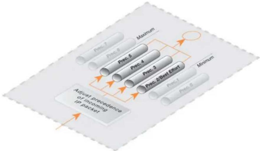
flowchart
graph TD
A["Prec. 0"] --> B["Adjust precedence of incoming IP packet"]
C["Prec. 1"] --> B
D["Prec. 2/Best Effort"] --> B
E["Prec. 3"] --> B
F["Prec. 4"] --> B
G["Prec. 5"] --> B
H["Prec. 6"] --> B
I["Prec. 7"] --> B
J["Maximum"] --> K["Minimum"]
Figure 11.5. Minimum and Maximum Pipe Precedence
Lowest Precedence Limits
It is usually not needed to have a limit specified for the lowest (best effort) precedence since this precedence simply uses any spare bandwidth not used by higher precedences. However, a limit could be specified if there is a need to restrict the bandwidth used by the lowest precedence. This might be the case if a particular traffic type always gets the lowest precedence but needs to have restricted bandwidth usage.
Precedences Only Apply When a Pipe is Full
Precedences have no effect until the total limit specified for a pipe is reached. This is true because until the pipe limit is reached (it becomes "full") there is no competition between precedences.
When the pipe is full, traffic is prioritized by NetDefendOS according to precedence with higher precedence packets that do not exceed the precedence limit being sent before lower precedence packets. Lower precedence packets are buffered until they can be sent. If buffer space becomes exhausted then they are dropped.
If a total limit for a pipe is not specified, it is the same as saying that the pipe has unlimited bandwidth and consequently it can never become full so precedences have no meaning.
Applying Precedences
Continuing to use the previous traffic shaping example, let us add the requirement that SSH and Telnet traffic is to have a higher priority than all other traffic. To do this we add a Pipe Rule specifically for SSH and Telnet and set the priority in the rule to be a higher priority, say 2. We specify the same pipes in this new rule as are used for other traffic.
The effect of doing this is that the SSH and Telnet rule sets the higher priority on packets related to these services and these packets are sent through the same pipe as other traffic. The pipe then makes sure that these higher priority packets are sent first when the total bandwidth limit
specified in the pipe's configuration is exceeded. Lower priority packets will be buffered and sent when higher priority traffic uses less than the maximum specified for the pipe. The buffering process is sometimes referred to as "throttling back" since it reduces the flow rate.
The Need for Guarantees
A problem can occur however if prioritized traffic is a continuous stream such as real-time audio, resulting in continuous use of all available bandwidth and resulting in unacceptably long queuing times for other services such as surfing, DNS or FTP. A means is required to ensure that lower priority traffic gets some portion of bandwidth and this is done with Bandwidth Guarantees.
Using Precedences as Guarantees
Specifying a limit for a precedence also guarantees that there is a minimum amount of bandwidth available for that precedence. Traffic flowing through a pipe will get the guarantee specified for the precedence it has, at the expense of traffic with lower precedences.
To change the prioritized SSH and Telnet traffic from the previous example to a 96 Kbps guarantee, the precedence 2 limit for the std-in pipe is set to be 96 Kbps.
This does not mean that inbound SSH and Telnet traffic is limited to 96 Kbps. Limits in precedences above the best effort precedence will only limit how much of the traffic gets to pass in that specific precedence.
If more than 96 Kbps of precedence 2 traffic arrives, any excess traffic will be moved down to the best effort precedence. All traffic at the best effort precedence is then forwarded on a first-come, first-forwarded basis.

Note: A limit on the lowest precedence has no meaning
Setting a maximum limit for the lowest (best effort) precedence or any lower precedences has no meaning and will be ignored by NetDefendOS.
Differentiated Guarantees
A problem arises if the aim is to give a specific 32 Kbps guarantee to Telnet traffic, and a specific 64 Kbps guarantee to SSH traffic. A 32 Kbps limit could be set for precedence 2, a 64 Kbps limit set for precedence 4 and then pass the different types of traffic through each precedence. However, there are two obvious problems with this approach:
- Which traffic is more important? This question does not pose much of a problem here, but it becomes more pronounced as the traffic shaping scenario becomes more complex.
- The number of precedences is limited. This may not be sufficient in all cases, even without the "which traffic is more important?" problem.
The solution is to create two new pipes: one for telnet traffic, and one for SSH traffic, much like the "surf" pipe that was created earlier.
First, remove the 96 Kbps limit from the std-in pipe, then create two new pipes: ssh-in and telnet-in. Set the default precedence for both pipes to 2, and the precedence 2 limits to 32 and 64 Kbps, respectively.
Then, split the previously defined rule covering ports 22 through 23 into two rules, covering 22
and 23, respectively:
Keep the forward chain of both rules as std-out only. Again, to simplify this example, we concentrate only on inbound traffic, which is the direction that is the most likely to be the first one to fill up in client-oriented setups.
Set the return chain of the port 22 rule to ssh-in followed by std-in.
Set the return chain of the port 23 rule to telnet-in followed by std-in.
Set the priority assignment for both rules to Use defaults from first pipe; the default precedence of both the ssh-in and telnet-in pipes is 2.
Using this approach rather than hard-coding precedence 2 in the rule set, it is easy to change the precedence of all SSH and Telnet traffic by changing the default precedence of the ssh-in and telnet-in pipes.
Notice that we did not set a total limit for the ssh-in and telnet-in pipes. We do not need to since the total limit will be enforced by the std-in pipe at the end of the respective chains.
The ssh-in and telnet-in pipes act as a "priority filter": they make sure that no more than the reserved amount, 64 and 32 Kbps, respectively, of precedence 2 traffic will reach std-in. SSH and Telnet traffic exceeding their guarantees will reach std-in as precedence 0, the best-effort precedence of the std-in and ssh-in pipes.

Note: The return chain ordering is important
Here, the ordering of the pipes in the return chain is important. Should std-in appear before ssh-in and telnet-in, then traffic will reach std-in at the lowest precedence only and hence compete for the 250 Kbps of available bandwidth with other traffic.
11.1.7. Pipe Groups
NetDefendOS provides a further level of control within pipes through the ability to split pipe bandwidth into individual resource users within a group and to apply a limit and guarantee to each user.
Individual users can be distinguished according to one of the following:
- Source IP
- Destination IP
- Source Network
- Destination Network
• Source Port (includes the IP)
• Destination Port (includes the IP) - Source Interface
- Destination Interface
This feature is enabled by enabling the Grouping option in a pipe. The individual users of a group can then have a limit and/or guarantee specified for them in the pipe. For example, if grouping is done by source IP then each user corresponds to each unique source IP address.
A Port Grouping Includes the IP Address
If a grouping by port is selected then this implicitly also includes the IP address. For example, port 1024 of host computer A is not the same as port 1024 of host computer B. It is the combination of port and IP address that identifies a unique user in a group.
Grouping by Networks Requires the Size
If the grouping is by source or destination network then the network size must also be specified. In other words, the netmask for the network must be specified for NetDefendOS.
Specifying Group Limits
Once the way the method of grouping is selected, the next step is to specify the Group Limits. These limits can consist of one or both of the following:
- Group Limit Total
This value specifies a limit for each user within the grouping. For example, if the grouping is by source IP address and the total specified is 100 Kbps then this is saying that no one IP address can take more than 100 Kbps of bandwidth.
• Group Precedence Guarantees
In addition to, or as an alternative to the total group limit, individual precedences can have values specified. These values are, in fact, guarantees (not limits) for each user in a group. For example, precedence 3 might have the value 50 Kbps and this is saying that an individual user (in other words, each source IP if that is the selected grouping) with that precedence will be guaranteed 50 Kbps at the expense of lower precedences.
The precedences for each user must be allocated by different pipe rules that trigger on particular users. For example, if grouping is by source IP then different pipe rules will trigger on different IPs and send the traffic into the same pipe with the appropriate precedence.
The potential sum of the precedence values could clearly become greater than the capacity of the pipe in some circumstances so it is important to specify the total pipe limit when using these guarantees.
Combining the Group Total and Precedences
Use of group precedences and the group total can be combined. This means that:
• The users in a group are first separated by pipe rules into precedences.
• The users are then subject to the guarantees specified for their precedence.
• The combined traffic is subject to the total group limit.
The illustration below shows this flow where the grouping has been selected to be according to source IP.

other
| Segment | Pipe Length | | ------- | ----------- | | Top Left | 192.168.123.5 | | Middle Left | 192.168.123.7 | | Bottom Right | 192.168.123.18 |Figure 11.6. Traffic Grouped By IP Address
Another Simple Groups Example
Consider another situation where the total bandwidth limit for a pipe is 400 Kbps. If the aim is to allocate this bandwidth amongst many destination IP addresses so that no single IP address can take more than 100 Kbps of bandwidth, the following steps are needed.
- Set the pipe limit, as usual, to be 400 Kbps.
- Set the Grouping option for the pipe to have the value Destination IP.
• Set the total for the pipe's Group Limits to be 100 Kbps.
Bandwidth is now allocated on a "first come, first forwarded" basis but no single destination IP address can ever take more than 100 Kbps. No matter how many connections are involved the combined total bandwidth can still not exceed the pipe limit of 400 Kbps.
Combining Pipe and Group Limit Precedence Values
Let us suppose that grouping is enabled by one of the options such as source IP and some values for precedences have been specified under Group Limits. How does these combine with values specified for the corresponding precedences in Pipe Limits?
In this case, the Group Limits precedence value is a guarantee and the Pipe Limits value for the same precedence is a limit. For example, if traffic is being grouped by source IP and the Group Limits precedence 5 value is 5 Kbps and the Pipe Limits precedence 5 value is 20 Kbps, then after the fourth unique source IP (4 x 5 = 20 Kbps) the precedence limit is reached and the guarantees may no longer be met.
Dynamic Balancing
Instead of specifying a total for Group Limits, the alternative is to enable the Dynamic Balancing option. This ensures that the available bandwidth is divided equally between all addresses
regardless of how many there are. This is done up to the limit of the pipe.
If a total group limit of 100 Kbps is also specified with dynamic balancing, then this still means that no single user may take more than that amount of bandwidth.
Precedences and Dynamic Balancing
As discussed, in addition to specifying a total limit for a grouping, limits can be specified for each precedence within a grouping. If we specify a precedence 2 grouping limit of 30 Kbps then this means that users assigned a precedence of 2 by a pipe rule will be guaranteed 30 Kbps no matter how many users are using the pipe. Just as with normal pipe precedences, traffic in excess of 30 Kbps for users at precedence 2 is moved down to the best effort precedence.
Continuing with the previous example, we could limit how much guaranteed bandwidth each inside user gets for inbound SSH traffic. This prevents a single user from using up all available high-priority bandwidth.
First we group the users of the ssh-in pipe so limits will apply to each user on the internal network. Since the packets are inbound, we select the grouping for the ssh-in pipe to be Destination IP.
Now specify per-user limits by setting the precedence 2 limit to 16 Kbps per user. This means that each user will get no more than a 16 Kbps guarantee for their SSH traffic. If desired, we could also limit the group total bandwidth for each user to some value, such as 40 Kbps.
There will be a problem if there are more than 5 users utilizing SSH simultaneously: 16 Kbps times 5 is more than 64 Kbps. The total limit for the pipe will still be in effect, and each user will have to compete for the available precedence 2 bandwidth the same way they have to compete for the lowest precedence bandwidth. Some users will still get their 16 Kbps, some will not.
Dynamic balancing can be enabled to improve this situation by making sure all of the 5 users get the same amount of limited bandwidth. When the 5th user begins to generate SSH traffic, balancing lowers the limit per user to about 13 Kbps (64 Kbps divided by 5 users).
Dynamic Balancing takes place within each precedence of a pipe individually. This means that if users are allotted a certain small amount of high priority traffic, and a larger chunk of best-effort traffic, all users will get their share of the high-precedence traffic as well as their fair share of the best-effort traffic.
11.1.8. Traffic Shaping with VPN and Tunnels
If using traffic shaping with IPsec or any tunneling protocol, the following should be noted:
• Tunnels introduce overhead
If traffic shaping is set up to measure the traffic inside VPN tunnels then it should be remembered that this is raw data without any overhead so it will usually be less than the bandwidth used by the tunnel that carries it. VPN protocols such as IPsec can add significant overhead to the data because of control data and encryption. For this reason, it is recommended that the limits specified in the traffic shaping pipes for tunneled IPsec data are set at around 20% below the actual available bandwidth.
- Pipe rules can trigger on either the tunnel or the data inside the tunnel
It is possible to initiate traffic shaping by having a Pipe Rule object that triggers either on the tunnel itself or the data that is being tunneled. The recommendation is to use pipe rules that trigger on the tunnel. This will mean that the bandwidth issue outlined in the previous point is avoided since traffic shaping will be measuring the outer tunnel data and not the data inside the tunnel.
If a Pipe Rule triggers on the tunnel itself, then it should be noted that the Source Interface property of the Pipe Rule should be set to a value of core. It should never be set to a value of any as this could mean that the rule could trigger twice. Once for the tunnel and once for the tunneled data.
11.1.9. Traffic Shaping Recommendations
The Importance of a Pipe Limit
Traffic shaping only comes into effect when a NetDefendOS pipe is full. That is to say, it is passing as much traffic as the total limit allows. If a 500 Kbps pipe is carrying 400 Kbps of low priority traffic and 90 Kbps of high priority traffic then there is 10 Kbps of bandwidth left and there is no reason to throttle back anything. It is therefore important to specify a total limit for a pipe so that it knows what its capacity is and the precedence mechanism is totally dependent on this.
Relying on the Group Limit
A special case when a total pipe limit is not specified is when a group limit is used instead. The bandwidth limit is then placed on, for example, each user of a network where the users must share a fixed bandwidth resource. An ISP might use this approach to limit individual user bandwidth by specifying a "Per Destination IP" grouping. Knowing when the pipe is full is not important since the only constraint is on each user. If precedences were used the pipe maximum would have to be used.
Limits should not be more than the Available Bandwidth
If pipe limits are set higher than the available bandwidth, the pipe will not know when the physical connection has reached its capacity. If the connection is 500 Kbps but the total pipe limit is set to 600 Kbps, the pipe will believe that it is not full and it will not throttle lower precedences.
Limits should be less than Available Bandwidth
Pipe limits should be slightly below the network bandwidth. A recommended value is to make the pipe limit 95% of the physical limit. The need for this difference becomes less with increasing bandwidth since 5% represents an increasingly larger piece of the total.
The reason for the lower pipe limit is how NetDefendOS processes traffic. For outbound connections where packets leave the firewall, there is always the possibility that NetDefendOS might slightly overload the connection because of the software delays involved in deciding to send packets and the packets actually being dispatched from buffers.
For inbound connections, there is less control over what is arriving and what has to be processed by the traffic shaping subsystem and it is therefore more important to set pipe limits slightly below the real connection limit to account for the time needed for NetDefendOS to adapt to changing conditions.
Attacks on Bandwidth
Traffic shaping cannot protect against incoming resource exhaustion attacks, such as DoS attacks or other flooding attacks. NetDefendOS will prevent these extraneous packets from reaching the hosts behind the firewall, but cannot protect the connection becoming overloaded if an attack floods it.
Watching for Leaks
When setting out to protect and shape a network bottleneck, make sure that all traffic passing through that bottleneck passes through the defined NetDefendOS pipes.
If there is traffic going through the Internet connection that the pipes do not know about, NetDefendOS cannot know when the Internet connection becomes full.
The problems resulting from leaks are exactly the same as in the cases described above. Traffic "leaking" through without being measured by pipes will have the same effect as bandwidth consumed by parties outside of administrator control but sharing the same connection.
Troubleshooting
For a better understanding of what is happening in a live setup, the console command:
gw-world:/> pipe -u <pipename>
can be used to display a list of currently active users in each pipe.
11.1.10. A Summary of Traffic Shaping
NetDefendOS traffic shaping provides a sophisticated set of mechanisms for controlling and prioritizing network packets. The following points summarize its use:
- Select the traffic to manage through Pipe Rules.
• Pipe Rules send traffic through Pipes.
• A pipe can have a limit which is the maximum amount of traffic allowed.
• A pipe can only know when it is full if a total limit for the pipe is specified.
• A single pipe should handle traffic in only one direction (although 2 way pipes are allowed). - Pipes can be chained so that one pipe's traffic feeds into another pipe.
• Specific traffic types can be given a priority in a pipe. - Priorities can be given a maximum limit which is also a guarantee. Traffic that exceeds this will be sent at the minimum precedence which is also called the Best Effort precedence.
- At the best effort precedence all packets are treated on a "first come, first forwarded" basis.
- Within a pipe, traffic can also be separated on a Group basis. For example, by source IP address. Each user in a group (for example, each source IP address) can be given a maximum limit and precedences within a group can be given a limit/guarantee.
• A pipe limit need not be specified if group members have a maximum limit. - Dynamic Balancing can be used to specify that all users in a group get a fair and equal amount of bandwidth.
11.1.11. More Pipe Examples
This section looks at some more scenarios and how traffic shaping can be used to solve particular problems.
A Basic Scenario
The first scenario will examine the configuration shown in the image below, in which incoming and outgoing traffic is to be limited to 1 megabit per second.
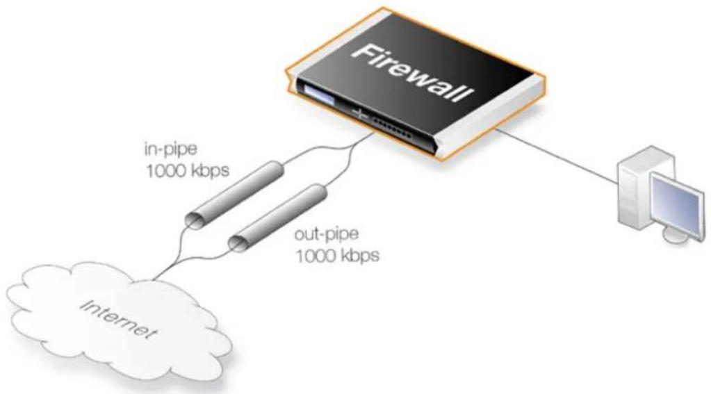
flowchart
graph TD
A["Firewall"] -->|in-pipe 1000 kbps| B["internet"]
A -->|out-pipe 1000 kbps| C["Computer"]
Figure 11.7. A Basic Traffic Shaping Scenario
The reason for using 2 different pipes in this case, is that these are easier to match to the physical link capacity. This is especially true with asynchronous links such as ADSL.
First, two pipes called in-pipe and out-pipe need to be created with the following parameters:
| Pipe Name | Min Prec | Def Prec | Max Prec | Grouping | Net size | Pipe limit |
| in-pipe 0 0 7 Per | DestIP 24 1000 Kbps | |||||
| out-pipe 0 0 7 Per | SrcIP 24 1000 Kbps |
Dynamic Balancing should be enabled for both pipes. Instead of PerDestIP and PerSrcIP we could have used PerDestNet and PerSrcNet if there were several networks on the inside.
The next step is to create the following Pipe Rule which will force traffic to flow through the pipes.
| Rule Name | Forward Pipes | Return Pipes | Source Interface | Source Network | Destination Interface | Destination Network | Selected Service |
| all_1mbps | out-pipe | in-pipe | lan | lannet | wan | all-nets | all_services |
The rule will force all traffic to the default precedence level and the pipes will limit total traffic to their 1 Mbps limit. Having Dynamic Balancing enabled on the pipes means that all users will be allocated a fair share of this capacity.
Using Several Precedences
We now extend the above example by allocating priorities to different kinds of traffic accessing the Internet from a headquarters office.
Assume there is a symmetric 2/2 Mbps link to the Internet. Descending priorities and traffic requirements will be allocated to the following users:
• Priority 6 - VoIP (500 Kbps)
• Priority 4 - Citrix (250 Kbps)
• Priority 2 - Other traffic (1000 Kpbs)
• Priority 0 - Web plus remaining from other levels
To implement this scheme, we can use the in-pipe and out-pipe. We first enter the Pipe Limits for each pipe. These limits correspond to the list above and are:
• Priority 6 - 500
• Priority 4 - 250
• Priority 2 - 1000
Now create the Pipe Rules:
| Rule Name | Forward Pipes | Return Pipes | Source Interface | Source Network | Dest Interface | Dest Network | Selected Service | Precedence |
| web_surf out | pipe in-pipe | lan lannet wan | all-nets http-all 0 | |||||
| voip out-pipe | in-pipe lan | lannet wan all-nets H323 6 | ||||||
| citrix out-pipe | in-pipe lan | lannet wan all-nets citrix 4 | ||||||
| other | out-pipe in-pipe | lan lannet | wan all-nets all_services 2 |
These rules are processed from top to bottom and force different kinds of traffic into precedences based on the Service. Customized service objects may need to be first created in order to identify particular types of traffic. The all service at the end, catches anything that falls through from earlier rules since it is important that no traffic bypasses the pipe rule set otherwise using pipes will not work.
Pipe Chaining
Suppose the requirement now is to limit the precedence 2 capacity (other traffic) to 1000 Kbps so that it does not spill over into precedence 0. This is done with pipe chaining where we create new pipes called in-other and out-other both with a Pipe Limit of 1000. The other pipe rule is then modified to use these:
| Rule Name | Forward Pipes | Return Pipes | Source Interface | Source Network | Dest Interface | Dest Network | Selected Service | Precedence |
| other | out-other out-pipe | in-other in-pipe | lan lannet | wan all-nets | all_services 2 |
Note that in-other and out-other are first in the pipe chain in both directions. This is because we want to limit the traffic immediately, before it enters the in-pipe and out-pipe and competes with VoIP, Citrix and Web-surfing traffic.
A VPN Scenario
In the cases discussed so far, all traffic shaping is occurring inside a single D-Link firewall. VPN is typically used for communication between a headquarters and branch offices in which case pipes can control traffic flow in both directions. With VPN it is the tunnel which is the source and destination interface for the pipe rules.
An important consideration which has been discussed previously, is allowance in the Pipe Total values for the overhead used by VPN protocols. As a rule of thumb, a pipe total of 1700 bps is reasonable for a VPN tunnel where the underlying physical connection capacity is 2 Mbps.
It is also important to remember to insert into the pipe all non-VPN traffic using the same physical link.
The pipe chaining can be used as a solution to the problem of VPN overhead. A limit which allows for this overhead is placed on the VPN tunnel traffic and non-VPN traffic is inserted into a pipe that matches the speed of the physical link.
To do this we first create separate pipes for the outgoing traffic and the incoming traffic. VoIP traffic will be sent over a VPN tunnel that will have a high priority. All other traffic will be sent at the best effort priority (see above for an explanation of this term). Again, a 2/2 Mbps symmetric link is assumed.
The pipes required will be:
• vpn-in
• Priority 6: VoIP 500 Kbps
• Priority 0: Best effort
Total: 1700
• vpn-out
• Priority 6: VoIP 500 Kbps
• Priority 0: Best effort
Total: 1700
- in-pipe
• Priority 6: VoIP 500 Kbps
Total: 2000
- out-pipe
• Priority 6: VoIP 500 Kbps
Total: 2000
The following pipe rules are then needed to force traffic into the correct pipes and precedence levels:
| Rule Name | Forward Pipes | Return Pipes | Src Int | Source Network | Dest Int | Destination Network | Selected Service | Prece dence |
| vpn voip_out vpn-out out-pipe | vpn-out in-pipe | vpn-in in-pipe | lan lan | net vpn vpn_remote_net H3 | 23 6 | |||
| vpn_out | vpn-out out-pipe | vpn-in in-pipe | lan lan | net vpn vpn_remote_net all | services 0 | |||
| vpn voip_in | vpn-in in-pipe | vpn-out out-pipe | vpn vpn | remote_net lan lan net H3 | 23 6 | |||
| vpn_in vpn-in | in-pipe | vpn-out out-pipe | vpn v | vpn_remote_net lan lan | net all | _services 0 | ||
| out out-pipe in-pipe | lan lann | et wan all-nets | all | services 0 | ||||
| in in-pipe out-pipe | wan all-nets | lan lann | et all | services 0 |
With this setup, all VPN traffic is limited to 1700 Kbps, the total traffic is limited to 2000 Kbps and VoIP to the remote site is guaranteed 500 Kbps of capacity before it is forced to best effort.
SAT with Pipes
If SAT is being used, for example with a web server or ftp server, that traffic also needs to be forced into pipes or it will escape traffic shaping and ruin the planned quality of service. In addition, server traffic is initiated from the outside so the order of pipes needs to be reversed: the forward pipe is the in-pipe and the return pipe is the out-pipe.
A simple solution is to put a "catch-all-inbound" rule at the bottom of the pipe rule. However, the external interface (wan) should be the source interface to avoid putting into pipes traffic that is coming from the inside and going to the external IP address. This last rule will therefore be:
| Rule Name | Forward Pipes | Return Pipes | Source Interface | Source Network | Dest Interface | Dest Network | Selected Service | Precedence |
| all-in | in-pipe | out-pipe | wan | all-nets | core | all-nets | all_services | 0 |

Note: SAT and ARPed IP Addresses
If the SAT is from an ARPed IP address, the wan interface needs to be the destination.
11.2. IDP Traffic Shaping
11.2.1. Overview
The IDP Traffic Shaping feature is traffic shaping that is performed based on information coming from the NetDefendOS Intrusion Detection and Prevention (IDP) subsystem (for more information on IDP see Section 7.6, "Intrusion Detection and Prevention").
This feature is set up by selecting a value of Pipe for the Action property of an IDP Rule. Some extra properties become available when this action is selected and these are described later in this section.
Application Related Bandwidth Usage
A typical problem that can be solved with IDP Traffic Shaping is dealing with the traffic management issues caused by bandwidth hungry applications. A typical example of this is traffic related to peer-to-peer (P2P) data transfer applications which include such things as Bit Torrent and Direct Connect.
The high traffic loads created by P2P transfers can often have a negative impact on the quality of service for other network users as bandwidth is quickly absorbed by such applications. An ISP or a corporate network administrator may therefore need to identify and control the bandwidth consumed by these applications and IDP Traffic Shaping can provide this ability.
Combining IDP and Traffic Shaping
One of the issues with controlling a traffic type such as P2P is to be able to distinguish it from other traffic. The signature database of NetDefendOS IDP already provides a highly effective means to perform this recognition and as an extension to this, NetDefendOS also provides the ability to apply throttling through the NetDefendOS traffic shaping subsystem when the targeted traffic is recognized.
IDP Traffic Shaping is a combination of these two features, where traffic flows identified by the IDP subsystem automatically trigger the setting up of traffic shaping pipes to control those flows.
11.2.2. Setting Up IDP Traffic Shaping
The steps for IDP Traffic Shaping setup are as follows:
- Define an IDP rule that triggers on target traffic.
The IDP signature chosen determines which traffic is to be targeted and the signature usually has the word "POLICY" in its name which indicates it relates to specific applications types.
- Select the rule's action to be the Pipe.
This specifies that IDP Traffic Shaping is to be performed on the connection that triggers the rule and on subsequent, related connections.
- Select a Bandwidth value for the pipe.
This is the total bandwidth that will be allowed for the target traffic. The traffic measured is the combination of the flow over the triggering connection plus the flow from any associated connections, regardless of flow direction.
Connections opened before IDP triggered will not be subject to any restriction.
4. Optionally enter a Time Window in seconds.
This will be the period of time after rule triggering during which traffic shaping is applied to any associated connections that are opened.
Typically, a P2P transfer starts with an initial connection to allow transfer of control information followed by a number of data transfer connections to other hosts.
It is the initial connection that IDP detects and the Time Window specifies the expected period afterwards when other connections will be opened and subject to traffic shaping. Connections opened after the Time Window has expired will no longer be subject to traffic shaping.
A Time Window value of 0 means that only traffic flowing over the initial triggering connection will be subject to traffic shaping. Any associated connections that do not trigger an IDP rule will not be subject to traffic shaping.
5. Optionally specify a Network
If the Time Window value is greater than zero, a Network can be specified. This IP address range allows the administrator to further refine the subsequent connections associated with IDP rule triggering that will be subject to traffic shaping. At least one side of associated connection has to be in the IP range specified for it to be included in traffic shaping.
11.2.3. Processing Flow
To better understand how IDP Traffic Shaping is applied, the following are the processing steps that occur:
- A new connection is opened by one host to another through the D-Link firewall and traffic begins to flow. The source and destination IP address of the connection is noted by NetDefendOS.
- The traffic flowing on the connection triggers an IDP rule. The IDP rule has Pipe as action so the traffic on the connection is now subject to the pipe traffic shaping bandwidth specified in the IDP rule.
- A new connection is then established that does not trigger an IDP rule but has a source or destination IP that is the same as the connection that did trigger a rule. If the source or destination is also a member of the IP range specified as the Network, then the connection's traffic is included in the pipe performing traffic shaping for the original triggering connection.
If no Network is specified then this new connection is also included in the triggering connection's pipe traffic if source or destination match.
11.2.4. The Importance of Specifying a Network
Either Side Can Trigger IDP
After reading through the processing flow description above, it can be better understood why specifying a Network is important. The IDP subsystem cannot know which side of a connection is causing a rule to trigger. Sometimes it is the initiating client side and sometimes the responding
server. If traffic flow on both sides becomes restricted, this may have the unintended consequence of traffic shaping connections that should not be traffic shaped.
Unintended Consequences
To explain this unintended traffic shaping, consider a client A that connects to host X with P2P traffic and triggers an IDP rule with the Pipe action so the connection becomes subject to traffic shaping. Now, if another client B also connects to host X but this time with web surfing traffic, an IDP rule is not triggered but the connection should not be traffic shaped along with client A's connection just because host X is involved.
Excluding Hosts
To avoid these unintended consequences, we specify the IPv4 addresses of client A and client B in the Network range but not host X. This tells NetDefendOS that host X is not relevant in making a decision about including new non-IDP-triggering connections in traffic shaping.
It may seem counter-intuitive that client B is also included in the Network range but this is done on the assumption that client B is a user whose traffic might also have to be traffic shaped if they become involved in a P2P transfer.
If Network is not specified then any connection involving either client A or host X will be subject to traffic shaping and this is probably not desirable.
11.2.5. A P2P Scenario
The schematic below illustrates a typical scenario involving P2P data transfer. The sequence of events is:
- The client with IP address 192.168.1.15 initiates a P2P file transfer through a connection (1) to the tracking server at 81.150.0.10.
- This connection triggers an IDP rule in NetDefendOS which is set up with an IDP signature that targets the P2P application.
- The Pipe action in the rule sets up a traffic shaping pipe with a specified capacity and the connection is added to it.
- A subsequent connection (2) to the file host at 92.92.92.92 occurs within the IDP rule's Time Window and its traffic is therefore added to the pipe and is subject to shaping.
- The client network to which 192.168.1.15 belongs, should ideally be included in the Network address range for the IDP rule.
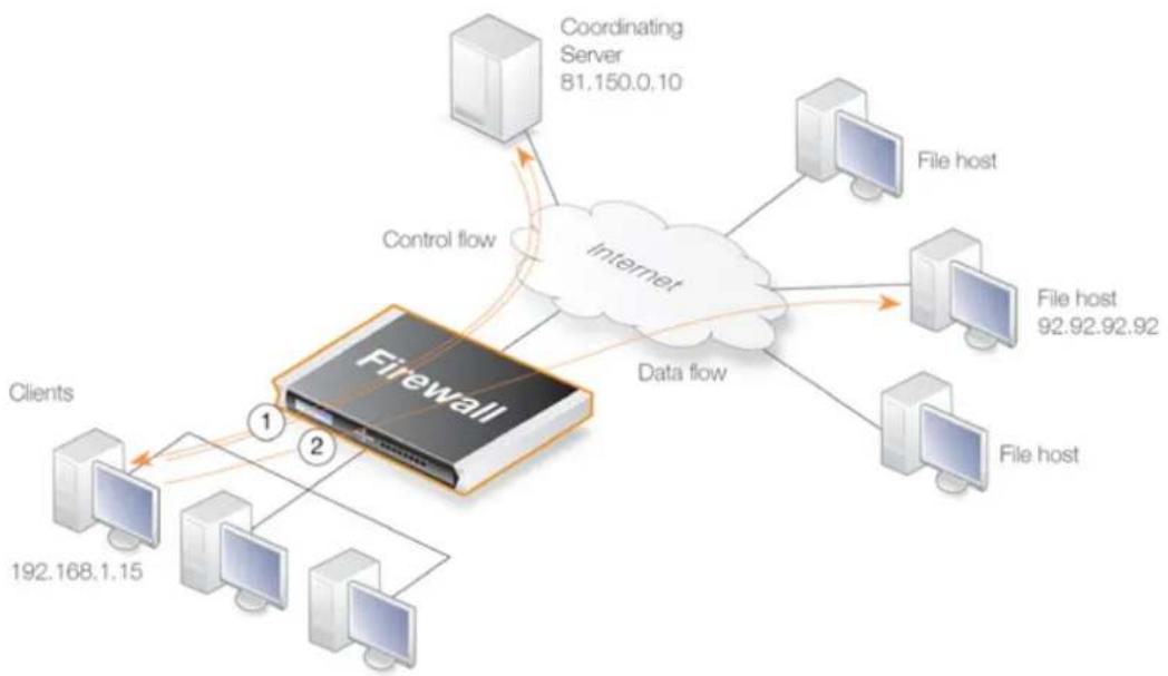
flowchart
graph TD
A["Firewall"] -->|Control flow| B["Coordinating Server 81.150.0.10"]
A --> C["Data flow"]
A --> D["Clients 192.168.1.15"]
A --> E["Clients 2"]
A --> F["Internet"]
F --> G["File host 92.92.92.92"]
F --> H["File host"]
Figure 11.8. IDP Traffic Shaping P2P Scenario
11.2.6. Viewing Traffic Shaping Objects
Viewing Hosts
IDP traffic shaping has a special CLI command associated with it called idppipes and this can examine and manipulate the hosts which are currently subject to traffic shaping.
To display all hosts being traffic shaped by IDP Traffic Shaping, the command would be:
gw-world:/> idppipes -show
Host kbps Tmout
192.168.1.1 100 58
A host, in this case with IP address 192.168.1.1, can be removed from traffic shaping using the command:
gw-world:/> idppipes -unpipe -host=192.168.1.1
A full description of the idppipes command can be found in the separate CLI Reference Guide.
Viewing Pipes
IDP Traffic Shaping makes use of normal NetDefendOS pipe objects which are created automatically. These pipes are always allocated the highest priority and use the Group feature to throttle traffic.
The created pipes are, however, hidden from the administrator when examining the currently defined traffic shaping objects with the Web Interface, but they can be examined and manipulated using the normal CLI pipes command. For example, to show all currently defined
pipes, the CLI command is:
gw-world:/> pipes -show
The IDP Traffic Shaping pipes can be recognized by their distinctive naming convention which is explained next.
Pipe Naming
NetDefendOS names the pipes it automatically creates in IDP Traffic Shaping using the pattern IDPPipe_
For example, the first pipes created with a limit of 1000 Kbps will be called IDPPipe_1000 for upstream traffic and IDPPipe_1000R for downstream traffic. Duplicates with the same limit would get the names IDPPipe_1000_(2) and IDPPipe_1000R_(2). If another set of duplicates occur, the suffix (3) is used.
Pipes are Shared
There is not a 1 to 1 relationship between a configured IDP action and the pipes created. Two pipes are created per configured bandwidth value, one for upstream (forward) traffic and one for downstream (return) traffic. Multiple hosts use the same pipe for each direction with traffic in the upstream pipe grouped using the "Per Source IP" feature and traffic in the downstream pipe grouped using the "Per Destination IP" feature.
11.2.7. Guaranteeing Instead of Limiting Bandwidth
If desired, IDP Traffic Shaping can be used to do the opposite of limiting bandwidth for certain applications.
If the administrator wants to guarantee a bandwidth level, say 10 Megabits, for an application then an IDP rule can be set up to trigger for that application with the Pipe action specifying the bandwidth required. The traffic shaping pipes that are then automatically created get the highest priority by default and are therefore guaranteed that bandwidth.
11.2.8. Logging
IDP Traffic Shaping generates log messages on the following events:
- When an IDP rule with the Pipe option has triggered and either host or client is present in the Network range.
- When the subsystem adds a host that will have future connections blocked.
- When a timer for piping news connections expires, a log message is generated indicating that new connections to or from the host are no longer piped.
There are also some other log messages which indicate less common conditions. All log messages are documented in the Log Reference Guide.
11.3. Server Load Balancing
11.3.1. Overview
The Server Load Balancing (SLB) feature allows the administrator to spread client application requests over a number of servers using an SLB Policy object. Alternatively an IP Rule with an Action of SLB_SAT could be used, although using an SLB Policy is recommended. Examples for both methods can be found in Section 11.3.7, "Setting Up SLB".
SLB is a powerful tool that can improve the following aspects of network applications:
- Performance
- Scalability
- Reliability
- Ease of administration
The principle SLB benefit of sharing the load across multiple servers can improve not just the performance of applications but also scalability by facilitating the implementation of a cluster of servers (sometimes referred to as a server farm) that can handle many more requests than a single server.

Note: SLB is not available on all NetDefend models
The SLB feature is not available on the DFL-260E.
The illustration below shows a typical SLB scenario, with Internet access to internal server applications by external clients being managed by a D-Link firewall.
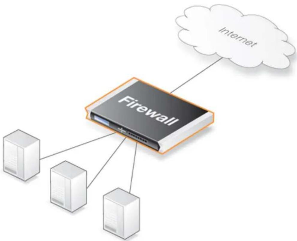
flowchart
graph TD
A["Firewall"] --> B["Server 1"]
A --> C["Server 2"]
A --> D["Server 3"]
A --> E["Internet"]
Figure 11.9. A Server Load Balancing Configuration
Additional Benefits of SLB
Besides improving performance and scalability, SLB provides other benefits:
- SLB increases the reliability of network applications by actively monitoring the servers sharing the load. NetDefendOS SLB can detect when a server fails or becomes congested and will not direct any further requests to that server until it recovers or has less load.
In addition, NetDefendOS can optionally send the appropriate error message back to the initiator of a server connection when failure of the server is detected via server monitoring.
- SLB can allow network administrators to perform maintenance tasks on servers or applications without disrupting services. Individual servers can be restarted, upgraded, removed, or replaced, and new servers and applications can be added or moved without affecting the rest of a server farm, or taking down applications.
- The combination of network monitoring and distributed load sharing also provides an extra level of protection against Denial Of Service (DoS) attacks.
SLB Deployment Considerations
The following issues should be considered when deploying SLB:
• Across which servers is the load is to be balanced.
• Which SLB algorithm will be used.
- Will "stickiness" be used.
• Which monitoring method will be used.
Each of these topics is discussed further in the sections that follow.
Identifying the Servers
An important first step in SLB deployment is to identify the servers across which the load is to be balanced. This might be a server farm which is a cluster of servers set up to work as a single "virtual server". The servers that are to be treated as a single virtual server by SLB must be specified.
11.3.2. SLB Distribution Algorithms
There are several ways to determine how a load is shared across a set of servers. NetDefendOS SLB supports the following two algorithms for load distribution:
- Round-robin
The algorithm distributes new incoming connections to a list of servers on a rotating basis. For the first connection, the algorithm picks a server randomly, and assigns the connection to it. For subsequent connections, the algorithm cycles through the server list and redirects the load to servers in order. Regardless of each server's capability and other aspects, for instance, the number of existing connections on a server or its response time, all the available servers take turns in being assigned the next connection.
This algorithm ensures that all servers receive an equal number of requests, therefore it is most suited to server farms where all servers have an equal capacity and the processing loads of all requests are likely to be similar.
- Connection-rate
This algorithm considers the number of requests that each server has been receiving over a certain time period. This time period is known as the Window Time. SLB sends the next request to the server that has received the least number of connections during the last Window Time number of seconds.
The Window Time is a setting that the administrator can change. The default value is 10 seconds.
- Resource-usage
This method depends on the servers sending back their loading information to NetDefendOS so the connection allocation can always go to the server with the least load.
The servers send back their loading information using the NetDefendOS REST API. Custom software that runs on servers must be written using this API. The API is fully described in the separate NetDefendOS REST API Guide.
Using the REST API requires that an appropriate Remote Management object is configured in NetDefendOS. This object allows access by external software that uses the API and setting this is up is described in the first chapter of the NetDefendOS REST API Guide.
11.3.3. Selecting Stickiness
In some scenarios, such as with SSL or TLS connections, it is important that the same server is used for a series of connections from the same client. This is achieved by selecting the appropriate stickiness option and this can be used with either the round-robin or connection-rate algorithms. The options for stickiness are as follows:
• Per-state Distribution
This mode is the default and means that no stickiness is applied. Every new connection is considered to be independent from other connections even if they come from the same IP address or network. Consecutive connections from the same client may therefore be passed to different servers.
This may not be acceptable if the same server must be used for a series of connections coming from the same client. If this is the case then stickiness is required.
- IP Address Stickiness
In this mode, a series of connections from a specific client will be handled by the same server. This is particularly important for TLS or SSL based services such as HTTPS, which require a repeated connection to the same host.
- Network Stickiness
This mode is similar to IP stickiness except that the stickiness can be associated with a network instead of a single IP address. The network is specified by stating its size as a parameter.
For example, if the network size is specified as 24 (the default) then an IP address 10.01.01.02 will be assumed to belong to the network 10.01.01.00/24 and this will be the network for which stickiness is applied.
Stickiness Properties
If either IP stickiness or network stickiness is enabled then the following stickiness properties can be adjusted:
- Idle Timeout
When a connection is made, the source IP address for the connection is remembered in a table. Each table entry is referred to as a slot. After it is created, the entry is only considered valid for the number of seconds specified by the Idle Timeout. When new connection is made, the table is searched for the same source IP, providing that the table entry has not exceeded its timeout. When a match is found, then stickiness ensures that the new connection goes to the same server as previous connections from the same source IP.
The default value for this setting is 10 seconds.
- Max Slots
This parameter specifies how many slots exist in the stickiness table. When the table fills up then the oldest entry is discarded to make way for a new entry even though it may be still valid (the Idle Timeout has not been exceeded).
The consequence of a full table can be that stickiness will be lost for any discarded source IP addresses. The administrator should therefore try to ensure that the Max Slots parameter is set to a value that can accommodate the expected number of connections that require stickiness.
The default value for this setting is 2048 slots in the table.
- Net Size
The processing and memory resources required to match individual IP addresses when implementing stickiness can be significant. By selecting the Network Stickiness option these resource demands can be reduced.
When the Network Stickiness option is selected, the Net Size parameter specifies the size of the network which should be associated with the source IP of new connections. A stickiness table lookup does not then compare individual IP addresses but instead compares if the source IP address belongs to the same network as a previous connection already in the table. If they belong to the same network then stickiness to the same server will result.
The default value for this setting is a network size of 24.
11.3.4. SLB Algorithms and Stickiness
This section discusses further how stickiness functions with the different SLB algorithms.
An example scenario is illustrated in the figure below. In this example, the D-Link firewall is responsible for balancing connections from 3 clients with different addresses to 2 servers. Stickiness is enabled.
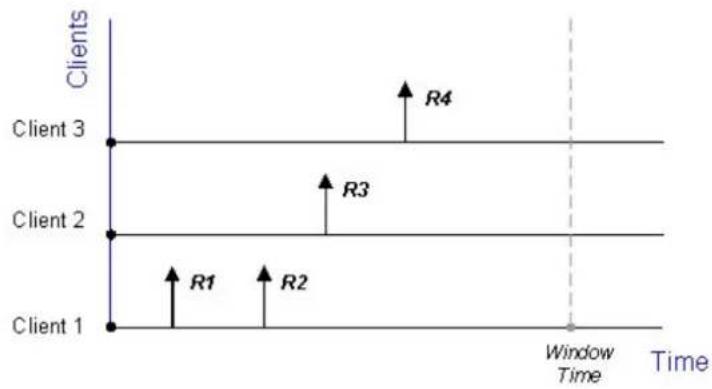
line
| Client | Start Time | End Time | | -------- | ---------- | -------- | | Client 1 | | | | Client 2 | | | | Client 3 | | | | R1 | | | | R2 | | | | R3 | | | | R4 | | |Figure 11.10. Connections from Three Clients
When the round-robin algorithm is used, the first arriving requests R1 and R2 from Client 1 are both assigned to one server, say Server 1, according to stickiness. The next request R3 from Client 2 is then routed to Server 2. When R4 from Client 3 arrives, Server 1 gets back its turn again and will be assigned with R4.
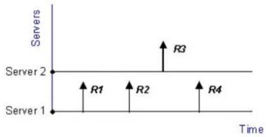
line
| Server | Time | Servers | |--------|------|---------| | Server 1 | 0 | 0 | | Server 1 | 1 | 0 | | Server 1 | 2 | 0 | | Server 1 | 3 | 0 | | Server 1 | 4 | 0 | | Server 2 | 0 | 0 | | Server 2 | 1 | 0 | | Server 2 | 2 | 0 | | Server 2 | 3 | 0 | | Server 2 | 4 | 0 | | Server 3 | 0 | 0 | | Server 3 | 1 | 0 | | Server 3 | 2 | 0 | | Server 3 | 3 | 0 | | Server 3 | 4 | 0 | | Server 4 | 0 | 0 | | Server 4 | 1 | 0 | | Server 4 | 2 | 0 | | Server 4 | 3 | 0 | | Server 4 | 4 | 0 |Figure 11.11. Stickiness and Round-Robin
If the connection-rate algorithm is applied instead, R1 and R2 will be sent to the same server because of stickiness, but the subsequent requests R3 and R4 will be routed to another server since the number of new connections on each server within the Window Time span is counted in for the distribution.
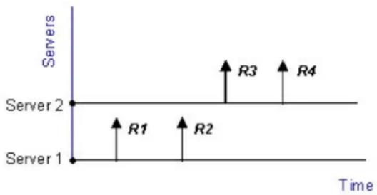
line
| Server | Time | Servers | |--------|------|---------| | Server 1 | 0 | 0 | | Server 2 | 0 | 0 | | Server 3 | 0 | 1 | | Server 4 | 0 | 0 |Figure 11.12. Stickiness and Connection-rate
Regardless which algorithm is chosen, if a server goes down, traffic will be sent to other servers. And when the server comes back online, it can automatically be placed back into the server farm and start getting requests again.
The Server Status Display and Pausing a Server
While SLB is active, its status can be viewed in the Web Interface by going to: Status > Server Load Balancing. There the server and number of allocated connections are displayed.
In the Maintenance column of the display for each server there is a Pause button and this can pressed to temporarily remove the server from having new connections distributed to it. Existing connections to the server will not be closed by NetDefendOS when a server is paused, but no new connections will be allocated.
However, if stickiness is enabled, new connections can continue to be allocated to a paused server to comply with the stickiness requirement.
11.3.5. Server Health Monitoring
SLB uses Server Health Monitoring to continuously check the condition of the servers in an SLB configuration. SLB can monitor different OSI layers to check the condition of each server. Regardless of the algorithms used, if a server is deemed to have failed, SLB will not open any more connections to it until the server is restored to full functionality.
D-Link Server Load Balancing provides the following monitoring modes:
ICMP Ping
This works at OSI layer 3. SLB will ping the IP address of each individual server in the server farm. This will detect any failed servers.
TCP Connection
This works at OSI layer 4. SLB attempts to connect to a specified port on each server. For example, if a server is specified as running web services on port 80, the SLB will send a TCP SYN request to that port. If SLB does not receive a TCP SYN/ACK back, it will mark port 80 on that server as down. SLB recognizes the conditions no response, normal response or closed port response from servers.
11.3.6. Behavior After Server Failure
If monitoring determines that a server is unavailable then new connections are automatically sent to servers that are still available. This section describes how NetDefendOS behaves when it detects that a server has failed but a connected client is not yet aware of the failure.
The Active Connection Reset Setting
If monitoring is used with SLB, there is an additional property available on both the IP Rule and SLB Policy objects which is called Active Connection Reset. This determines how NetDefendOS will handle existing connections after server failure.
A Summary of NetDefendOS Behavior
The following describes the actions that NetDefendOS will take depending on the protocol and whether the Active Connection Reset setting is enabled:
• Active Connection Reset Setting Disabled (the default)
Depending on the protocol, the following will happen when a client sends a packet to a failed server:
i. TCP
NetDefendOS closes the connection and sends back TCP RST.
ii. UDP
NetDefendOS closes the connection and sends back ICMP Port Unreachable (3).
iii. ICMP or other protocol
NetDefendOS closes the connection and sends back ICMP Protocol Unreachable (2).
• Active Connection Reset Setting Enabled
Depending on the protocol, the following will happen immediately after the server is detected as failed:
i. TCP
NetDefendOS closes the connection and sends back TCP RST immediately after failure detection.
ii. UDP
NetDefendOS closes the connection immediately after failure detection and sends no message
iii. ICMP or other protocol
NetDefendOS closes the connection immediately after failure detection and sends no message.
Note that if a server client sends traffic after NetDefendOS closes the connection then it will be
treated as a new connection and routed to a functioning server.

Caution: Active Connection Reset consumes resources
If the Active Connection Reset setting is enabled, additional processing resources are required by NetDefendOS to track the state of every connection. With large numbers of connections, this has the potential to impact traffic flow through the firewall.
11.3.7. Setting Up SLB
This section contains examples that illustrate how SLB is set up using first an SLB Policy object and then an alternative method using an IP Rule. Using an SLB Policy is the recommended method.
The following steps should be used for setting up SLB.
- Define an IP address object for each server for which SLB is to be enabled.
- Define an IP address group object which includes all these individual objects.
- Define an SLB Policy object in the IP rule set which refers to this IP address group. The destination interface is always specified as core in the policy meaning NetDefendOS itself deals with the connection.
Example 11.3. Setting up SLB with an SLB Policy
In this example, server load balancing is performed between two HTTP web servers situated behind the D-Link firewall. These web servers have the private IPv4 addresses 192.168.1.10 and 192.168.1.11. Access by external clients is via the wan interface which has the IPv4 address wan_ip.
The default SLB values for monitoring, distribution method and stickiness are used.
Command-Line Interface
A. Create an address object for each of the web servers:
gw-world:/> add Address IP4Address server1 Address=192.168.1.10
gw-world:/> add Address IP4Address server2 Address=192.168.1.11
B. Specify the SLB Policy object:
gw-world:/> add SLBPolicy Name=my_web_slb_policy
SourceInterface=wan
SourceNetwork=all-nets
DestinationInterface=core
DestinationNetwork=wan_ip
Service=http-all
SLBAddresses=server1, server2
The above will only allow access by external clients on the Internet. To also allow internal clients on Iannet access, the IP Policy must be rewritten using an Interface Group object which combines both the wan and lan interfaces.
A-2: First, create the InterfaceGroup:
gw-world:/> add Interface InterfaceGroup my_if_group Members=wan,lan
B-2: Now, create an SLBPolicy object:
gw-world:/> add SLBPolicy Name=my_web_slb_policy
SourceInterface=my_if_group
SourceNetwork=all-nets
DestinationInterface=core
DestinationNetwork=wan_ip
Service=http-all
SLBAddresses=my_server_group
Web Interface
A. Create an Object for each of the web servers:
- Go to: Objects > Address Book > Add > IP4 Address
- Enter a suitable name, in this example server1
- Enter the IP Address as 192.168.1.10
- Click OK
- Repeat the above to create an object called server2 for the 192.168.1.11 IP address
B. Specify the SLB\_SAT IP rule:
- Go to: Policies > Firewalling > Main IP Rules > Add > SLB Policy
- Now enter:
- Name: my_web_slb_policy
- Source Interface: wan
- Source Network: all-nets
- Destination Interface: core
- Destination Network: wan_ip
• Service: http-all
-
Add server1 and server2 to Selected
-
Click OK
The above will only allow access by external clients on the Internet. To also allow internal clients on Iannet access, the IP Policy must be rewritten using an Interface Group object which combines both the wan and lan interfaces.
A-2: First, create an InterfaceGroup:
-
Go to: Network > Interfaces and VPN > Interface Groups > Add > Interface Group
-
Now enter:
-
Name: my_if_group
• Selected: wan and lan -
Add server1 and server2 to Selected
-
Click OK
B-2. Now, create the SLBPolicy object:
- Go to: Policies > Firewalling > Main IP Rules > Add > SLB Policy
-
Now enter:
-
Name: my_web_slb_policy
- Source Interface: my_if_group
• Source Network: all-nets - Destination Interface: core
-
Destination Network: wan_ip
• Service: http-all
• Selected: server1 and server2 -
Click OK
Example 11.4. Setting up SLB with IP Rules
In this example, server load balancing is performed between two HTTP web servers situated behind the D-Link firewall. These web servers have the private IPv4 addresses 192.168.1.10 and 192.168.1.11. Access by external clients is via the wan interface which has the IPv4 address wan_ip.
The default SLB values for monitoring, distribution method and stickiness are used.
A NAT rule is used in conjunction with the SLB_SAT rule so that clients behind the firewall can access the web servers. An Allow rule is used to allow access by external clients.
Command-Line Interface
A. Create an address object for each of the web servers:
gw-world:/> add Address IP4Address server1 Address=192.168.1.10
gw-world:/> add Address IP4Address server2 Address=192.168.1.11
B. Create an IP4Group which contains the 2 web server addresses:
gw-world:/> add Address IP4Group server_group Members=server1,server2
C. Specify the SLB_SAT IP rule:
gw-world:/> add IPRule Action=SLB_SAT
SourceInterface=any
SourceNetwork=all-nets
DestinationInterface=core
DestinationNetwork=wan_ip
Service=http-all
SLBAddresses=server_group
Name=web_slb
D. Specify a NAT rule for internal clients access to the servers:
gw-world:/> add IPRule Action=NAT
SourceInterface=lan
SourceNetwork=lan-net
DestinationInterface=core
DestinationNetwork=wan_ip
Service=http-all
NATAction=UseInterfaceAddress
Name=web_slb_nat
E. Specify an Allow IP rule for the external clients:
gw-world:/> add IPRule Action=Allow
SourceInterface=wan
SourceNetwork=all-nets
DestinationInterface=core
DestinationNetwork=wan_ip
Service=http-all
NATAction=UseInterfaceAddress
Name=web_slb_allow
Web Interface
A. Create an Object for each of the web servers:
- Go to: Objects > Address Book > Add > IP4 Address
- Enter a suitable name, for example server1
- Enter the IP Address as 192.168.1.10
- Click OK
-
Repeat the above to create an object called server2 for the 192.168.1.11 IP address
B. Create an IP4Group which contains the 2 web server addresses: -
Go to: Objects > Address Book > Add > IP4 Group
- Enter a suitable name, for example server_group
- Add server1 and server2 to the group
- Click OK
C. Specify the SLB\_SAT IP rule:
-
Go to: Policies > Firewalling > Main IP Rules > Add > IP Rule
-
Now enter:
-
Name: web_slb
• Action: SLB_SAT
• Service: HTTP - Source Interface: wan
- Source Network: all-nets
- Destination Interface: core
- Destination Network: wan_ip
3. Select SAT SLB
-
Under Server Addresses add server_group to Selected
-
Click OK
D. Specify a NAT rule for internal clients access to the servers:
-
Go to: Policies > Firewalling > Main IP Rules > Add > IP Rule
-
Now enter:
-
Name: web_slb_nat
• Action: NAT
• Service: http-all - Source Interface: Ian
- Source Network: Ian_net
- Destination Interface: core
- Destination Network: wan_ip
3. Click OK
E. Specify an Allow IP rule for the external clients:
-
Go to: Policies > Firewalling > Main IP Rules > Add > IP Rule
-
Now enter:
-
Name: web_slb_allow
-
Action: Allow
• Service: http-all -
Source Interface: wan
- Source Network: all-nets
- Destination Interface: core
- Destination Network: wan_ip
3. Click OK

Note: FwdFast IP rules should not be used with SLB
In order to function, SLB requires that the NetDefendOS state engine keeps track of connections. If using IP rules, FwdFast rules should not be used with SLB since packets that are forwarded by these rules are not under state engine control.
Chapter 12: High Availability
This chapter describes the high availability fault-tolerance feature in NetDefendOS.
• Overview, page 938
• HA Mechanisms, page 941
- Setting Up HA, page 945
• HA Issues, page 952
- Upgrading an HA Cluster, page 955
• Link Monitoring and HA, page 957
• HA Advanced Settings, page 958
12.1. Overview
HA Clusters
NetDefendOS High Availability (HA) provides a fault tolerant capability for D-Link firewall installations. HA works by adding a back-up slave D-Link firewall to an existing master firewall. The master and slave are connected together by a synchronization link and make up a logical HA Cluster. One of the units in a cluster will be active while the other unit will be inactive and on standby.
Initially, the cluster slave will be inactive and will only monitor the activity of the master. If the slave detects that the master has become inoperative, an HA failover takes place and the slave becomes active, assuming processing responsibility for all traffic. If the master later becomes operative again, the slave will continue to be active but the master will now monitor the slave with failover only taking place if the slave fails. This is sometimes known as an active-passive implementation of fault tolerance.

Note: HA is not available on all NetDefend models
The HA feature is not available on the DFL-260E and DFL-860E.
HA Requires Similar Hardware
The master and slave in an HA cluster will normally have identical D-Link hardware configurations and D-Link does not support clusters that use dissimilar hardware. An HA cluster made up of two dissimilar hardware models is not supported by D-Link.
The Master and Active Units
When reading this section on HA, it should be kept in mind that the master unit in a cluster is not always the same as the active unit in a cluster.
The active unit is the firewall that is actually processing all traffic at a given point in time. This could be the slave unit if a failover has occurred because the master is no longer operational.
Interconnection of Cluster Units
In a cluster, the master and slave units must be directly connected to each other by a synchronization connection which is known to NetDefendOS as the sync interface. One of the normal interfaces on the master and the slave are dedicated for this purpose and are connected together with a crossover cable.
Special packets, known as heartbeats, are continually sent by NetDefendOS from one cluster unit to the other across Ethernet interfaces which have been configured as sync interfaces. These are also sent on all other Ethernet interfaces unless an interface is explicitly configured not to send them. These special packets allow the health of both units to be monitored. Heartbeat packets are sent in both directions so that the passive unit knows about the health of the active unit and the active unit knows about the health of the passive.
The heartbeat mechanism is discussed below with more detail in Section 12.2, "HA Mechanisms".
Cluster Management
When managing the cluster through the Web Interface or CLI, the configuration on one cluster unit can be changed and this will then be automatically copied to the other unit, provided that automatic synchronization is enabled for both cluster units (by default, it is). Turning off automatic synchronization and changing the cluster units separately is not recommended.
Automatic synchronization involves a process of one unit failing over to the other when a configuration change is saved. For example, if a change is made to the inactive unit and saved, the inactive unit will become the active unit so the other cluster unit can be updated. It does not matter if the changes are made to the active or inactive unit although it is usual practice to change the inactive unit.
When the active unit is changed, two failovers occur. The active unit first goes inactive so it can update, then becomes active again as the other unit updates. This method leaves the active unit as still the active unit and this can be desirable in some circumstances. For example, where a feature does not support HA, such as L2TP, connections will not be lost
Example 12.1. Enabling Automatic Cluster Synchronization
This example enables automatic cluster synchronization on a D-Link firewall which is already part of an HA cluster. This setting is enabled by default when HA is enabled but this example is provided for completeness. This setting should always be set to the same value on both cluster units.
Command-Line Interface
gw-world:/> set HighAvailability Sync=Yes
Web Interface
- Go to: System > Device > High Availability
- Enable the option: Synchronize Configuration
- Click OK
Load Sharing
D-Link HA clusters do not provide a load sharing capability since only one unit will be active while the other is inactive and only two firewalls, the master and the slave, can exist in a single cluster. The only processing role that the inactive unit plays is to replicate the state of the active unit and to take over all traffic processing if it detects the active unit is not responding.
Extending Redundancy
Implementing an HA Cluster will eliminate one of the points of failure in a network. Routers, switches and Internet connections can remain as potential points of failure and redundancy for these should also be considered.
Protecting Against Network Failures Using HA and Link Monitor
The NetDefendOS Link Monitor feature can be used to check connection with a host so that when it is no longer reachable an HA failover is initiated to a peer which has a different connection to the host. This technique is a useful extension to normal HA usage which provides protection against network failures between a single D-Link firewall and hosts. This technique is described further in Section 2.4.2, "The Link Monitor".
12.2. HA Mechanisms
This section discusses in more depth the mechanisms NetDefendOS uses to implement the high availability feature.
Basic Principles
D-Link HA provides a redundant, state-synchronized hardware configuration. The state of the active unit, such as the connection table and other vital information, is continuously copied to the inactive unit via the sync interface. When cluster failover occurs, the inactive unit knows which connections are active, and traffic can continue to flow after the failover with negligible disruption.
The inactive system detects that the active system is no longer operational when it no longer detects sufficient Cluster Heartbeats. Heartbeats are sent over the sync interface as well as all other interfaces.
Heartbeat Frequency
NetDefendOS sends 5 heartbeats per second from the active system and when three heartbeats are missed (that is to say, after 0.6 seconds) a failover will be initiated. By sending heartbeats over all interfaces, the inactive unit gets an overall view of the active unit's health. Even if sync is deliberately disconnected, failover may not result if the inactive unit receives enough heartbeats from other interfaces via a shared switch, however the sync interface sends twice as many heartbeats as any of the normal interfaces.
Heartbeats are not sent at smaller intervals because such delays may occur during normal operation. An operation, for example opening a file, could result in delays long enough to cause the inactive system to go active, even though the other is still active.

Important: Disabling sending heartbeats on interfaces
The administrator can manually disable heartbeat sending on any interface if that is desired. This is a property of the Ethernet interface configuration object. This is not recommended since the fewer interfaces that send heartbeats, the higher the risk that not enough heartbeats are received to correctly determine system health.
The exception to this recommendation is if an Ethernet interface is not used at all. It is recommended to disable heartbeat sending on unused interfaces. The reason for this is that sending heartbeats on unused interfaces contributes to a false picture of system health since those heartbeats are always lost. A "false" failover could therefore be the result or possibly even both units becoming the active unit.
Heartbeat Characteristics
Cluster heartbeats have the following characteristics:
• The source IP is the interface address of the sending firewall.
• The destination IP is the broadcast address on the sending interface.
- The IP TTL is always 255. If NetDefendOS receives a cluster heartbeat with any other TTL, it is assumed that the packet has traversed a router and therefore cannot be trusted.
• It is a UDP packet, sent from port 999, to port 999.
- The destination MAC address is the multicast version of the shared hardware address and if UniqueSharedMac is enabled (the default) this has the form:
$$ 1 1 - 0 0 - 0 0 - 0 0 - m m - m m - n n $$
Where mm is a bit mask made up of the interface bus, slot and port on the master and nn represents the cluster ID. If UniqueSharedMac is not enabled, the form is:
$$ 1 1 - 0 0 - 0 0 - c 1 - 4 a - n n $$
Link layer multicasts are used over normal unicast packets for security. Using unicast packets would mean that a local attacker could fool switches to route heartbeats somewhere else so the inactive system never receives them.
Failover Time
The time for failover is typically about one second which means that clients may experience a failover as a slight burst of packet loss. In the case of TCP, the failover time is well within the range of normal retransmit timeouts so TCP will retransmit the lost packets within a very short space of time, and continue communication. UDP does not allow retransmission since it is inherently an unreliable protocol.
Shared IP Addresses and ARP
Both master and slave know about the shared IP address. ARP queries for the shared IP address, or any other IP address published via the ARP configuration section or through Proxy ARP, are answered by the active system.
The hardware address of the shared IP address and other published addresses are not related to the actual hardware addresses of the interfaces. Instead the MAC address is constructed by NetDefendOS from the Cluster ID. If UniqueSharedMac is enabled (the default), its form is:
$$ 1 0 - 0 0 - 0 0 - \mathrm{mm} - \mathrm{mm} - \mathrm{nn} $$
Where mm is derived from the master node's bus/slot/port combined and nn is the configured Cluster ID. The Cluster ID must be unique for each NetDefendOS cluster in a network. If UniqueSharedMac is not enabled the form is:
$$ 1 0 - 0 0 - 0 0 - C 1 - 4 A - n n $$
As the shared IP address always has the same hardware address, there will be no latency time in updating ARP caches of units attached to the same LAN as the cluster when failover occurs.
When a cluster member discovers that its peer is not operational, it broadcasts gratuitous ARP queries on all interfaces using the shared hardware address as the sender address. This allows switches to re-learn within milliseconds where to send packets destined for the shared address. The only delay in failover therefore, is detecting that the active unit is down.
ARP queries are also broadcast periodically to ensure that switches do not forget where to send packets destined for the shared hardware address.
Promiscuous Mode
The Ethernet interfaces in an HA cluster must operate in promiscuous mode for HA to function. This mode means that traffic with a destination MAC address that does not match the Ethernet interface's MAC address will be sent to NetDefendOS and not discarded by the interface. Promiscuous mode is enabled automatically by NetDefendOS and the administrator does not
need to worry about doing this.
If the administrator enters a CLI command ifstat
HA with Anti-Virus and IDP
If a NetDefendOS cluster has the Anti-Virus or IDP subsystems enabled then updates to the Anti-Virus signature database or IDP pattern database will routinely occur. These updates involve downloads from the external D-Link databases and they require NetDefendOS reconfiguration to occur for the new database contents to become active.
A database update causes the following sequence of events to occur in an HA cluster:
- The active (master) unit downloads the new database files from the D-Link servers. The download is done via the shared IP address of the cluster.
- The active (master) node sends the new database files to the inactive peer.
- The inactive (slave) unit reconfigures to activate the new database files.
- The active (master) unit now reconfigures to activate the new database files causing a failover to the slave unit. The slave is now the active unit.
- After reconfiguration of the master is complete, failover occurs again so that the master once again becomes the active unit.
Dealing with Sync Failure
An unusual situation that can occur in an HA cluster is if the sync connection between the master and slave experiences a failure with the result that heartbeats and state updates are no longer received by the inactive unit.
Should such a failure occur then the consequence is that both units will continue to function but they will lose their synchronization with each other. In other words, the inactive unit will no longer have a correct copy of the state of the active unit. A failover will not occur in this situation since the inactive unit will realize that synchronization has been lost.
Failure of the sync interface results in the generation of hasync_connection_failed_timeout log messages by the active unit. However, it should be noted that this log message is also generated whenever the inactive unit appears to be not working, such as during a software upgrade.
Failure of the sync interface can be confirmed by comparing the output from certain CLI commands for each unit. The number of connections could be compared with the stats command. If IPsec tunnels are heavily used, the ipsecglobalstat -verbose command could be used instead and significant differences in the numbers of IPsec SAs, IKE SAs, active users and IP pool statistics would indicate a failure to synchronize.
Once the broken sync interface is fixed, perhaps by replacing the connecting cable, resynchronization of the two units will take place automatically. If the sync interface is now functioning correctly, there may still be some small differences in the statistics from each cluster unit but these will be minor compared with the differences seen in the case of failure.
In unusual circumstances, synchronization between the active and inactive unit will not take place automatically. In this case, it may be necessary to manually restart the unsynchronized inactive unit in order to force resynchronization. This can be achieved using the CLI command:
A restart of the inactive unit will cause the following to take place:
- During startup, the inactive unit sends a message to the active unit to flag that its state has been initialized and it requires the entire state of the active unit to be sent.
• The active unit then sends a copy of its entire state to the inactive unit. - The inactive unit then becomes synchronized after which a failover can take place successfully if there is a system failure.
A restart of the inactive unit is the only time when the entire state of the active unit is sent to the inactive unit.
12.3. Setting Up HA
This section provides a step-by-step guide for setting up an HA Cluster. Setup is explained in the following subsections:
- Physical setup of the HA cluster and decisions about IP addresses is first discussed in Section 12.3.1, "Hardware Setup".
- Configuration of NetDefendOS is then discussed and this is divided into:
i. Using the Web Interface wizard is discussed in Section 12.3.2, "Wizard HA Setup".
ii. Performing NetDefendOS setup without the wizard is discussed in Section 12.3.3, "Manual HA Setup".
- Lastly, verifying HA operation is discussed in Section 12.3.4, "Verifying that the Cluster Functions Correctly".
12.3.1. Hardware Setup
The steps for the setup of hardware in an HA cluster are as follows:
- Start with two identical D-Link firewalls of the same model and with the same set of available Ethernet interfaces. Both may be newly purchased or an existing hardware unit may have a new unit added to it to create the cluster.
- Both master and slave units must be running the same version of NetDefendOS.
- Make the physical connections:
- Connect the matching interfaces of master and slave through separate switches or separate broadcast domains. It is important to keep the traffic on each interface pair separated from other pairs.
- Select one unique interface on the master and slave which is to be used by the units for monitoring each other. This will be the sync interface. It is recommended that the same interface is used on both master and slave, assuming they are similar systems.

Caution: The sync interface must be unique
With some hardware, an interface may be part of a switch fabric which joins a set of interfaces together.
If such an interface is used as the HA sync interface then the other interfaces connected to the same switch fabric cannot be used for other purposes.
Also keep in mind that there should be no NetDefendOS IP rule set entries configured that include the sync interface.
- Connect together the sync interfaces. This can be done directly with a suitable cable or through a separate switch (or broadcast domain).
- Decide on a shared IP address for each interface in the cluster. Some interfaces could have shared addresses only while others could also have unique, individual IP addresses for each interface specified in an IP4 HA Address object. The shared and individual addresses are used as follows:
- The individual addresses specified for an interface in an IP4 HA Address object allow remote management through that interface. These addresses can also be "pinged" using ICMP provided that IP rule set entries are defined to permit this (by default, ICMP queries are dropped by the rule set).
If either unit is inoperative, its individual IP addresses will also be unreachable. These IP addresses are usually private but must be public if management access across the Internet is required.
If an interface is not assigned an individual address through an IP4 HA Address object then it must be assigned the default address localhost (the loopback address) which is an IP address from the sub-network 127.0.0.0/8. The localhost object behaves as two addresses and uses 127.0.0.1 for the master and 127.0.0.2 for the slave.
ARP queries for the individual IP addresses specified in IP4 HA Address objects are answered by the firewall that owns the address, using the normal hardware address, just as with normal IP units.
- One single shared IP address is used for routing and it is also the address used by dynamic address translation, unless the configuration explicitly specifies another address.

Note: Master and slave management IPs must be different
The shared IP address cannot be used for remote management or monitoring purposes. For example, when using SSH for remote management of the firewalls in an HA Cluster, the individual IP addresses of each firewall's interfaces must be used and these are specified in IP4 HA Address objects as discussed above.
For this reason the management IP addresses of the cluster units must be different. It is recommended to change the management IP address of the slave unit so it is different from the master. Changing the management IP is described in Section 2.1.2, "Configuring Management Access".
Typical HA Cluster Network Connections
The illustration below shows the arrangement of typical HA Cluster connections in a network. All interfaces on the master unit would normally also have corresponding interfaces on the slave unit and these would be connected to the same networks. This is achieved by connecting the same interfaces on both master and slave via a separate switch (or broadcast domain) to other network portions.
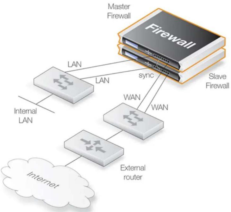
flowchart
graph TD
A["Master Firewall"] -->|LAN| B["Internal LAN"]
A -->|LAN| C["External router"]
A -->|sync| D["Slave Firewall"]
D -->|WAN| E["External router"]
F["Internet"] --> C
Figure 12.1. High Availability Setup
In the HA setup shown above, the lan interface on the master and the lan interface on the slave would be connected to the same switch which then connects to an internal network. Similarly the wan interface on the master and the wan interface would connect to a switch which in turn connects to the external Internet.

Note: The illustration shows a crossover cable sync connection
The illustration above shows a direct crossover cable connection between the sync interfaces of each unit. Alternatively, the connection could be via a switch or broadcast domain.
Wizard and Manual Software Setup
The software setup procedures are now divided into the two sections that follow:
• Section 12.3.2, "Wizard HA Setup" for fast, simple setup.
• Section 12.3.3, "Manual HA Setup" for step by step manual setup, without the wizard.
12.3.2. Wizard HA Setup
NetDefendOS provides a wizard to automate the HA setup procedure. The wizard needs to be run twice: once when connected to the master unit in the HA cluster, and a second time when connected to the slave unit in the cluster. The procedure for doing this with each unit is as follows:
- Connect to the D-Link firewall through the Web Interface.
- Go to: Objects > Address Book and create an IP4 HA Address object for each interface pair in the cluster. Each object will contain the master and slave IP addresses for the interface pair. Inclusion in an IP4 HA Address object is mandatory for any interface that will be used for remote management but optional for other interfaces. The private address must be different in the IP4 HA Address object for the management interface of the master and slave unit.
- Save and activate the new configuration before continuing to the next step.
- Go to System > Device > High Availability in the web interface and press the Start Wizard button. Running the wizard for the master and slave units is described in A and B below.
- Save and activate the new configuration.
A. Running the Wizard for Master Setup
- Specify the NodeType, ClusterID and Interface that will be used for synchronization.
- If the two hardware models used in the cluster are different, this should also be indicated (see Section 12.3.5, "Unique Shared Mac Addresses" below for an explanation of this option).
- Select the shared IP address and, if desired, the individual IP4 HA Address objects created earlier. Make sure the management interface IPs are different for master and slave.
- The wizard will confirm that master setup is complete.
B. Running the Wizard for Slave Setup
- Specify the NodeType, ClusterID and Interface that will be used for synchronization.
- If the two hardware models used in the cluster are different, this should also be indicated (see Section 12.3.5, "Unique Shared Mac Addresses" below for an explanation of this option).
- The wizard will acknowledge that it will synchronize with the master unit.
- Select the desired interface mapping.
- The wizard will confirm that slave setup and synchronization is complete.
Installing a New Master Unit
It should be noted in the above process that the HA wizard synchronizes the slave from the master unit and not the other way around. This means that if the slave unit is swapped with a new unit, perhaps because of an equipment failure, the wizard can be used to perform the initial setup since it will copy over the configuration from the master.
But what if it is the slave unit that contains the configuration that is to be used and it is the master unit that is to be synchronized with it? This would be the case if the master unit suffered a
fault and had to be swapped with a brand new unit.
There are two methods to resolve this:
Method A. Copying the slave configuration to the new master
The easiest and quickest way to configure a new master unit is as follows:
- Use the normal configuration backup function to make a backup of the configuration that exists on the existing slave unit.
- Restore the backup from the slave to the new master unit.
- Through the management interface, change the new master unit's HA designation to be Master and rename the device so both do not have the same name.
Method B. Turning the slave into the master
A second, slightly more complicated approach, is to turn the slave unit into a master and then use the wizard as normal to copy the configuration across.
Changing the slave to the master is done through the management interface by changing the unit's HA designation to be Master. However, a remaining issue will be that the ARP caches of connected switches will not now be valid. To force an update of these caches either the switches should be restarted or the CLI command arp -notify could be issued from the new master (which was previously the slave).
This process of changing a slave to a master must be done quickly since there will be a reversion to the old configuration within the Validation Timeout period, which, by default, is 30 seconds. Within that time, the ARP cache problem must also be addressed. To solve this issue we can either commit the new configuration manually before dealing with the ARP issue, or lengthen the time available by increasing the advanced setting Validation Timeout.
12.3.3. Manual HA Setup
To set up an HA cluster manually, without the wizard, the steps are as follows:
- Connect to the master unit with the Web Interface.
- Go to: System > Device > High Availability.
- Check the Enable High Availability checkbox.
- Set the Cluster ID. This must be unique for each cluster.
- Choose the Sync Interface.
-
Select the node type to be Master.
-
Go to: Objects > Address Book and create an IP4 HA Address object for each interface pair. Each must contain the master and slave interface IP addresses for the pair.
Creating an object is mandatory for an interface pair used for remote management, but optional for other interfaces (in which case the default loopback address localhost must be used and this is an IP address from the 127.0.0.0/8 sub-network). The IPv4 address for the management interfaces of the master and slave units must be different.
- Optionally create an IP6 HA Address object for any relevant interface pairs. Management access or logging is not possible using an IPv6 address. However, a private IPv6 address could be pinged by incoming ICMP messages when the HA cluster is active or used as the
source IP for outgoing ICMP ping messages when HA is not active.
- Go to: Network > Interfaces and VPN > Ethernet and go through each interface in the list, entering the shared IP address for that interface in the IP Address field.
Also select the Advanced tab for each interface and set the High Availability, Private IP Address field to be the name of the IP4 HA Address object created previously for the interface (NetDefendOS will automatically select the appropriate address from the master and slave addresses defined in the object).

Note: IP addresses could be public IPv4 addresses
The term "private IPv4 address" is not strictly correct when used here. Either address used in an IP4 HA Address object may be public if management access across the Internet is required.
- Save and activate the new configuration.
- Repeat the above steps for the other D-Link firewall but this time select the node type to be Slave.
Making Cluster Configuration Changes
The configuration on both firewalls needs to be the same. When using the Web Interface or CLI for management the configurations of the two units will be automatically synchronized, provided automatic synchronization is enabled. To change something in a cluster configuration, log on to either the master or the slave unit as an administrator, make the change, then save and activate. The change is automatically made to both units. Automatic synchronization is discussed in more depth in Section 12.1, "Overview".
12.3.4. Verifying that the Cluster Functions Correctly

Important: Perform shutdown on both master and slave
After the cluster has been configured, it is highly recommended to perform a shutdown operation on both cluster units so they restart at approximately the same time. This is done separately for each unit through the Web Interface or using the CLI command:
This will ensure both units will try to correctly synchronize with each other.
This step can be skipped but may be necessary later if synchronization does not succeed or other problems occur.
To verify that the cluster is performing correctly, first use the ha command on each unit. The output will look similar to the following for the master:
gw-world:/> ha
This device is an HA MASTER
This device is currently ACTIVE (will forward traffic)
HA cluster peer is ALIVE
Then use the stat command to verify that both the master and slave have about the same
number of connections. The output from the command should contain a line similar to the following:
Connections 2726 out of 128000
The lower number on the left in this output is the current number of connections and the higher number on the right is the maximum number of connections allowed by the license.
The following points are also relevant to cluster setup:
- If this is not the first cluster in a network then the Cluster ID must be changed for the cluster so that it is unique (the default value is 0). The Cluster ID determines that the MAC address for the cluster is unique.
- Enabling the advanced setting Use Unique Share MAC is recommended so that each interface has its own MAC address. If this is not enabled, interfaces share a MAC address and this can confuse some third party switches.
- Make sure that the advanced setting High Buffers (found in System > Advanced Settings > Misc. Settings in the Web Interface) is set to be automatic for both units in the cluster. This setting determines how memory is allocated by NetDefendOS for handling increasing numbers of connections. A NetDefendOS restart is required for a change in this setting to take effect and this can be achieved with the CLI command:
Where a cluster has a very high number (for example, tens of thousands) of simultaneous connections then it may be necessary to set a high value for this instead of enabling the Dynamic High Buffers option. A very high value for High Buffers can suit situations with large numbers of connections but can have the disadvantage of increasing throughput.
See Section 13.10, "Miscellaneous Settings" for a full explanation of these settings.
12.3.5. Unique Shared Mac Addresses
For HA setup, NetDefendOS provides the advanced option Use Unique Shared MAC Address. By default, this is enabled and in most configurations it should not need to be disabled.
Enabling a Unique Shared MAC Address
The effect of enabling this setting is that a single, unique MAC address will be used for each pair of matching hardware interfaces so that, for example, the lan1 interface on the master unit will appear to have the same MAC address as the lan1 interface on the slave unit.
Problem Diagnosis
An HA cluster will function if this setting is disabled but can cause problems with a limited number of switch types where the switch uses a shared ARP table. Such problems can be hard to diagnose which is why it is best to always have the setting enabled.
12.4. HA Issues
The following points should be kept in mind when configuring and managing an HA Cluster.
ALGs are Not State Synchronized
No aspect of ALGs are state synchronized in a NetDefendOS high availability cluster. This means that all traffic handled by ALGs will freeze when a cluster fails over to the other peer. However, if the cluster fails back over to the original peer within approximately half a minute, frozen sessions and their associated transfers should begin working again.
Transparent Mode
There is no loop avoidance with HA so this should not be configured with HA. Switch routes and therefore transparent mode do not have state synchronization.
VPN Tunnel Synchronization
NetDefendOS provides complete synchronization for IPsec tunnels in an HA cluster. In the event of a failover occurring, incoming clients should not need to re-establish their tunnels.
However, NetDefendOS does not provide HA support for the following:
• PPTP
• L2TP
• L2TPv3
- SSL VPN
In the event of a failover occurring for these types of tunnel, incoming clients must re-establish their tunnels after the original tunnels are deemed non-functional. The timeout for this varies depending on the client and is typically within the range of a few seconds to a few minutes.
DHCP
Servers for IPv4 DHCP as well as DHCPv6 have full HA synchronization support. However, the clients for both IPv4 DHCP and DHCPv6 are not supported. If either type of client is configured on an interface, this will result in the error message Shared HA IP address not set when trying to commit the configuration.
Real-time Monitoring
The Real-time Monitor will not automatically track the active firewall. If a Real-time Monitor graph shows nothing but the connection count moving, then the cluster has probably failed over to the other unit.
All Cluster Interfaces Need IP Addresses
All interfaces on both HA cluster units should have a valid private IP4 address object assigned to them. The predefined IP object local host could be assigned for this purpose. The need to assign an address is true even if an interface has been disabled.
SNMP
SNMP statistics are not shared between master and slave. SNMP managers have no failover capabilities. Therefore both firewalls in a cluster need to be polled separately.
Logging
Log data will be coming from both master and slave. This means that the log receiver will have to be configured to receive logs from both. It also means that all log queries will likely have to include both master and slave as sources which will give all the log data in one result view. Normally, the inactive unit will not be sending log entries about live traffic so the output should look similar to that from one D-Link firewall.
Using Individual IP Addresses
The unique individual IP addresses of the master and slave cannot safely be used for anything but management. Using them for anything else, such as for source IPs in dynamically NATed connections or publishing services on them, will inevitably cause problems since unique IPs will disappear when the firewall they belong to does.
The Shared IP Must Not Be 0.0.0.0
Assigning the IPv4 address 0.0.0.0 as the shared IP address must be avoided. This is not valid for this purpose and will cause NetDefendOS to enter Lockdown Mode.
Failed Interfaces
Failed interfaces will not be detected unless they fail to the point where NetDefendOS cannot continue to function. This means that failover will not occur if the active unit can still send "I am alive" heartbeats to the inactive unit through any of its interfaces, even though one or more interfaces may be inoperative.
However, by utilizing the NetDefendOS link monitoring feature, NetDefendOS can be configured to trigger immediate HA failover on interface failure. This is discussed further in Section 12.6, "Link Monitoring and HA".
Changing the Cluster ID
Changing the cluster ID in a live environment is not recommended for two reasons. Firstly this will change the hardware address of the shared IPs and will cause problems for all devices attached to the local network, as they will keep the old hardware address in their ARP caches until it times out. Such units would have to have their ARP caches flushed.
Secondly, this breaks the connection between the firewalls in the cluster for as long as they are using different configurations. This will cause both firewalls to go active at the same time.
Invalid Checksums in Heartbeat Packets
Cluster Heartbeats packets are deliberately created with invalid checksums. This is done so that they will not be routed. Some routers may flag this invalid checksum in their log messages.
Making OSPF work
If OSPF is being used to determine routing metrics then a cluster cannot be used as the designated router.
If OSPF is to work then there must be another designated router available in the same OSPF area as the cluster. Ideally, there will also be a second, backup designated router to provide OSPF metrics if the main designated router should fail.
PPPoE Tunnels and DHCP Clients
For reasons connected with the shared IP addresses of an HA cluster, PPPoE tunnels and DHCP clients should not be configured in an HA cluster.
Disabling Heartbeats on Unused Interfaces
It is recommended to disable heartbeats on Ethernet interfaces that are not being used. If this is not done there is a risk that this could cause repeated failovers or even both units going active because the HA mechanism will see the unused interface as a failed interface. The higher the proportion of unused interfaces there are in a cluster, the more pronounced the effect of sending heartbeats on unused interfaces becomes.
Both Units Going Active
In the case of a misconfiguration of an HA cluster, a worst case scenario could arise where both the master and slave think the other unit has failed and both can go active at the same time resulting in the failure of correct traffic flow.
This is usually identified by examining the log messages generated by both units. An active-active situation might be caused by unused interfaces not having heartbeats turned off (as discussed previously) or possibly a connection problem such as the sync interfaces not being able to communicate.
12.5. Upgrading an HA Cluster
The NetDefendOS software versions running on the master and slave in an HA cluster should be the same. When a new NetDefendOS version becomes available and is to be installed on both units, the upgrade is done one unit at a time.
The central principal in the upgrade process for a cluster is that upgrading the inactive unit will not affect the operation of the cluster and only momentarily make the inactive unit unavailable.
The overall sequence of steps to follow is:
i. Identify which unit is inactive and upgrade that first.
ii. When the inactive unit is once again synchronized with the active unit, cause a failover to occur so that the inactive becomes the active unit.
iii. Now upgrade the inactive unit. Both units will then resynchronize and have the new NetDefendOS version.
These three steps will now be broken down into a more detailed description:
A. Establish which is the inactive unit in the cluster
The currently inactive unit will be upgraded first so it is necessary to identify this. To do this, connect with a CLI console to one of the cluster units and issue the ha command. The typical output if the unit is active is shown below.
gw-world:/> ha
This device is a HA SLAVE
This device is currently ACTIVE (will forward traffic)
This device has been active: 430697 sec
HA cluster peer is ALIVE
This unit (the slave) is the currently active unit, so the other one (the master) is the inactive unit.
B. Upgrade the inactive unit
Once the inactive unit is identified, upgrade this unit with the new NetDefendOS version. This is done exactly as though the unit were not in a cluster. For example, the Web Interface can be used to do the upgrade.

Important: Make sure the inactive unit is ALIVE
Before going to the next step make sure the inactive unit is fully operational and synchronized with the active unit after the software upgrade completes.
To do this, issue the CLI ha command on the inactive unit. The output from the command should indicate that the status is ALIVE.
gw-world:/> ha
This device is a HA SLAVE
This device is currently INACTIVE (won't forward traffic)
This device has been inactive: 2 sec
HA cluster peer is ALIVE
C. Cause a failover to occur
Now, connect to the active unit (which is still running the old NetDefendOS version) with a CLI console and issue the ha-deactivate command. This will cause the active unit to become inactive, and the inactive to become active.
gw-world:/> ha -deactivate
HA Was: ACTIVE
HA going INACTIVE...
To check that the failover has completed successfully, an ha command can be issued again and the text "INACTIVE" and "is ALIVE" should appear in the output.
D. Upgrade the newly inactive unit
When the failover is complete, upgrade the newly inactive unit with the new NetDefendOS version. Just like step B, this is done in the normal way as though the unit were not part of a cluster.
E. Wait for resynchronization
Once the second software upgrade is complete, two units will automatically resynchronize and the cluster will continue operation. The roles of active and inactive unit will have been reversed.
If it is desirable to make the active unit inactive, and the inactive unit active, the CLI command ha-active can be used.
12.6. Link Monitoring and HA
Redundant Network Paths
When using an HA configuration, it can be important to use redundant paths to vital resources such as the Internet. The paths through the network from the master device in an HA configuration may fail in which case it may be desirable to have this failure trigger a failover to the slave unit which has a different path to the resource.
Monitoring Paths
Monitoring the availability of specific network paths can be done with the NetDefendOS Link Monitor. The Link Monitor allows the administrator to specify particular hosts whose reachability is monitored using ICMP "Ping" requests and therefore link status. If these hosts become unreachable then the link is considered failed and a failover to a slave can be initiated. Provided that the slave is using a different network link and also monitoring the reachability of different hosts, traffic can continue to flow.
Using the Shared IP Address
When this property of the Link Monitor object is enabled, it allows the link monitor pings to be sent from the shared IP address instead of sending using the individual IPs of each unit. This is useful if public IPv4 addresses are not available for the sending interface.
Further Link Monitor Reading
Using link monitoring is described further in Section 2.4.2, "The Link Monitor".
12.7. HA Advanced Settings
The following NetDefendOS advanced settings are available for High Availability:
Sync Buffer Size
How much sync data, in Kbytes, to buffer while waiting for acknowledgments from the cluster peer.
Default: 4096
Sync Packet Max Burst
The maximum number of state sync packets NetDefendOS can send in a burst.
Default: 100
Initial Silence
The time in seconds to stay silent on startup or after reconfiguration. When the active unit in an HA cluster believes the inactive unit is no longer reachable, it continues to send synchronization traffic normally for a period of one minute in the expectation that the inactive unit will again become reachable. In order not to flood the network unnecessarily, after one minute has elapsed, the synchronization traffic is then only sent after repeated periods of silence. The length of this silence is taken from this setting.
Default: 5
Use Unique Shared Mac
Use a unique shared MAC address for each interface. For further explanation of this setting see Section 12.3.5, "Unique Shared Mac Addresses".
Default: Enabled
Deactivate Before Reconf
If enabled, this setting will make an active node failover to the inactive node before a reconfigure takes place instead of relying on the inactive node detecting that the active node is not operating normally and then taking over on its own initiative. Enabling this setting shortens the time where no node is active during configuration deployments.
Default: Enabled
Reconf Failover Time
Number of non-responsive seconds before failover at HA reconfiguration. The default value of zero means immediate reconfiguration.
Default: 0
HA Failover Time
Number of milliseconds that the active unit in the cluster has been unresponsive before a failover is initiated by the inactive unit.
Default: 750
Chapter 13: Advanced Settings
This chapter describes the additional configurable advanced settings for NetDefendOS that are not already described in the manual. In the Web Interface these settings are found under System > Advanced Settings.
The settings are divided up into the following categories:

Note: Activating setting changes
After any advanced setting is changed, the new NetDefendOS configuration must be activated in order for the new value to take effect.
• IP Level Settings, page 961
• TCP Settings, page 965
• ICMP Settings, page 971
• State Settings, page 972
- Connection Timeout Settings, page 974
• Length Limit Settings, page 976
- Fragmentation Settings, page 979
- Local Fragment Reassembly Settings, page 983
- SSL/TLS Settings, page 984
• Miscellaneous Settings, page 987
13.1. IP Level Settings
Log Checksum Errors
Logs occurrences of IP packets containing erroneous checksums. Normally, this is the result of the packet being damaged during network transport. All network units, both routers and workstations, drop IP packets that contain checksum errors. However, it is highly unlikely for an
attack to be based on illegal checksums.
Default: Enabled
Log non IPv4/IPv6
Logs occurrences of IP packets that are not IPv4 or IPv6.
Default: Enabled
Log Received TTL 0
Logs occurrences of IP packets received with the "Time To Live" (TTL) value set to zero. Under no circumstances should any network unit send packets with a TTL of 0.
Default: Enabled
Block 0000 Src
Block 0.0.0.0 as source address.
Default: Drop
Block 0 Net
Block 0.* as source addresses.
Default: DropLog
Block 127 Net
Block 127.* as source addresses.
Default: DropLog
Block Multicast Src
Block multicast both source addresses (224.0.0.0 - 255.255.255.255).
Default: DropLog
TTL Min
The minimum TTL value accepted on receipt.
Default: 3
TTL on Low
Determines the action taken on packets whose TTL falls below the stipulated TTLMin value.
Default: DropLog
Multicast TTL on Low
What action to take on too low multicast TTL values.
Default: DropLog
Default TTL
Indicates which TTL NetDefendOS is to use when originating a packet. These values are usually between 64 and 255.
Default: 255
Layer Size Consistency
Verifies that the size information contained in each "layer" (Ethernet, IP, TCP, UDP, ICMP) is consistent with that of other layers.
Default: ValidateLogBad
SecuRemoteUDP Compatibility
Allow IP data to contain eight bytes more than the UDP total length field specifies. Checkpoint SecuRemote violates NAT-T drafts.
Default: Disabled
IP Option Sizes
Verifies the size of "IP options". These options are small blocks of information that may be added to the end of each IP header. This function checks the size of well-known option types and ensures that no option exceeds the size limit stipulated by the IP header itself.
Default: ValidateLogBad
IP Option Source/Return
Indicates whether source routing options are to be permitted. These options allow the sender of the packet to control how the packet is to be routed through each router and firewall. These constitute an enormous security risk. NetDefendOS never obeys the source routes specified by these options, regardless of this setting.
Default: DropLog
IP Options Timestamps
Time stamp options instruct each router and firewall on the packet's route to indicate at what time the packet was forwarded along the route. These options do not occur in normal traffic. Time stamps may also be used to "record" the route a packet has taken from sender to final destination. NetDefendOS never enters information into these options, regardless of this setting.
Default: DropLog
IP router alert option
How to handle IP packets with contained route alert.
Default: ValidateLogBad
IP Options Other
All options other than those specified above.
Default: DropLog
Directed Broadcasts
Indicates whether NetDefendOS will forward packets which are directed to the broadcast address of its directly connected networks. It is possible to achieve this functionality by adding lines to the Rules section, but it is also included here for simplicity's sake. This form of validation is faster than entries in the Rules section since it is more specialized.
Default: DropLog
IP Reserved Flag
Indicates what NetDefendOS will do if there is data in the "reserved" fields of IP headers. In normal circumstances, these fields should read 0. Used by OS Fingerprinting.
Default: DropLog
Strip DontFragment
Strip the Don't Fragment flag for packets equal to or smaller than the size specified by this setting.
Default: 65535 bytes
Multicast Mismatch option
What action to take when Ethernet and IP multicast addresses does not match.
Default: DropLog
Min Broadcast TTL option
The shortest IP broadcast Time-To-Live value accepted on receipt.
Default: 1
Low Broadcast TTL Action option
What action to take on too low broadcast TTL values.
Default: DropLog
13.2. TCP Settings
TCP Option Sizes
Verifies the size of TCP options. This function acts in the same way as IPOptionSizes described above.
Default: ValidateLogBad
TCP MSS Min
Determines the minimum permissible size of the TCP MSS. Packets containing maximum segment sizes below this limit are handled according to the next setting.
Default: 100 bytes
TCP MSS on Low
Determines the action taken on packets whose TCP MSS option falls below the stipulated TCPMSSMin value. Values that are too low could cause problems in poorly written TCP stacks.
Default: DropLog
TCP MSS Max
Determines the maximum permissible TCP MSS size. Packets containing maximum segment sizes exceeding this limit are handled according to the next setting.
Default: 1460 bytes
TCP MSS VPN Max
As is the case with TCPMSSMax, this is the highest Maximum Segment Size allowed. However, this setting only controls MSS in VPN connections. This way, NetDefendOS can reduce the effective segment size used by TCP in all VPN connections. This reduces TCP fragmentation in the VPN connection even if hosts do not know how to perform MTU discovery.
This setting must be less than the maximum IPsec MTU size and the maximum IPsec MTU size must be less than the maximum packet size handled by the physical interface.
Default: 1400 bytes
TCP MSS On High
Determines the action taken on packets whose TCP MSS option exceeds the stipulated TCPMSSMax value. Values that are too high could cause problems in poorly written TCP stacks or give rise to large quantities of fragmented packets, which will adversely affect performance.
Default: Adjust
TCP MSS Log Level
Determines when to log regarding too high TCP MSS, if not logged by TCPMSSOnHigh.
Default: 7000 bytes
TCP Auto Clamping
Automatically clamp TCP MSS according to MTU of involved interfaces, in addition to TCPMSSMax.
Default: Enabled
TCP Zero Unused ACK
Determines whether NetDefendOS should set the ACK sequence number field in TCP packets to zero if it is not used. Some operating systems reveal sequence number information this way, which can make it easier for intruders wanting to hijack established connections.
Default: Enabled
TCP Zero Unused URG
Strips the URG pointers from all packets.
Default: Enabled
TCP Option WSOPT
Determines how NetDefendOS will handle window-scaling options. These are used to increase the size of the window used by TCP; that is to say, the amount of information that can be sent before the sender expects ACK. They are also used by OS Fingerprinting. WSOPT is a common occurrence in modern networks.
Default: ValidateLogBad
TCP Option SACK
Determines how NetDefendOS will handle selective acknowledgment options. These options are used to ACK individual packets instead of entire series, which can increase the performance of connections experiencing extensive packet loss. They are also used by OS Fingerprinting. SACK is a common occurrence in modern networks.
Default: ValidateLogBad
TCP Option TSOPT
Determines how NetDefendOS will handle time stamp options. As stipulated by the PAWS (Protect Against Wrapped Sequence numbers) method, TSOPT is used to prevent the sequence numbers (a 32-bit figure) from "exceeding" their upper limit without the recipient being aware of it.
This is not normally a problem. Using TSOPT, some TCP stacks optimize their connection by measuring the time it takes for a packet to travel to and from its destination. This information can then be used to generate resends faster than is usually the case. It is also used by OS Fingerprinting. TSOPT is a common occurrence in modern networks.
Default: ValidateLogBad
TCP Option ALTCHKREQ
Determines how NetDefendOS will handle alternate checksum request options. These options were initially intended to be used in negotiating for the use of better checksums in TCP.
However, these are not understood by any today's standard systems. As NetDefendOS cannot understand checksum algorithms other than the standard algorithm, these options can never be accepted. The ALTCHKREQ option is normally never seen on modern networks.
Note that this TCP option is obsoleted by RFC 6247 and only some network equipment will make use of it.
Default: StripLog
TCP Option ALTCHKDATA
Determines how NetDefendOS will handle alternate checksum data options. These options are used to transport alternate checksums where permitted by ALTCHKREQ above. Normally never seen on modern networks.
Note that this TCP option is obsoleted by RFC 6247 and only some network equipment will make use of it.
Default: StripLog
TCP Option CC
Determines how NetDefendOS will handle connection count options.
Note that this TCP option is obsoleted by RFC 6247 and only some network equipment will make use of it.
Default: StripLogBad
TCP Option Other
Specifies how NetDefendOS will deal with TCP options not covered by the above settings. These options usually never appear on modern networks.
Default: StripLog
TCP SYN/URG
Specifies how NetDefendOS will deal with TCP packets with SYN (synchronize) flags and URG (urgent data) flags both turned on. The presence of a SYN flag indicates that a new connection is in the process of being opened, and an URG flag means that the packet contains data requiring urgent attention. These two flags should not be turned on in a single packet as they are used exclusively to crash computers with poorly implemented TCP stacks.
Default: DropLog
TCP SYN/PSH
Specifies how NetDefendOS will deal with TCP packets with SYN and PSH (push) flags both turned on. The PSH flag means that the recipient stack should immediately send the information in the packet to the destination application in the computer.
These two flags should not be turned on at the same time as it could pose a crash risk for poorly implemented TCP stacks. However, some Apple MAC systems implement TCP in a non-standard way, meaning that they always send out SYN packets with the PSH flag turned on. This is why NetDefendOS normally removes the PSH flag and allows the packet through despite the fact that such packets would be dropped if standards were strictly followed.
Default: StripSilent
TCP SYN/RST
The TCP RST flag together with SYN; normally invalid (strip=strip RST).
Default: DropLog
TCP SYN/FIN
The TCP FIN flag together with SYN; normally invalid (strip=strip FIN).
Default: DropLog
TCP FIN/URG
Specifies how NetDefendOS will deal with TCP packets with both FIN (Finish, close connection) and URG flags turned on. This should normally never occur, as it is not usually attempted to close a connection at the same time as sending "important" data. This flag combination could be used to crash poorly implemented TCP stacks and is also used by OS Fingerprinting.
Default: DropLog
TCP URG
Specifies how NetDefendOS will deal with TCP packets with the URG flag turned on, regardless of any other flags. Many TCP stacks and applications deal with Urgent flags in the wrong way and can, in the worst case scenario, cease working. Note however that some programs, such as FTP and MS SQL Server, nearly always use the URG flag.
Default: StripLog
TCP ENC
Specifies how NetDefendOS will deal with TCP packets with either the Xmas or Ymas flag turned on. These flags are currently mostly used by OS Fingerprinting.
It should be noted that a developing standard called Explicit Congestion Notification also makes use of these TCP flags, but as long as there are only a few operating systems supporting this standard, the flags should be stripped.
Default: StripLog
TCP Reserved Field
Specifies how NetDefendOS will deal with information present in the "reserved field" in the TCP header, which should normally be 0. This field is not the same as the Xmas and Ymas flags. Used by OS Fingerprinting.
Default: DropLog
TCP NULL
Specifies how NetDefendOS will deal with TCP packets that do not have any of the SYN, ACK, FIN or RST flags turned on. According to the TCP standard, such packets are illegal and are used by both OS Fingerprinting and stealth port scanners, as some firewalls are unable to detect them.
Default: DropLog
TCP Sequence Numbers
Determines if the sequence number range occupied by a TCP segment will be compared to the receive window announced by the receiving peer before the segment is forwarded.
TCP sequence number validation is only possible on connections tracked by the state-engine (not on packets forwarded using a FwdFast rule).
Possible values are:
- Ignore - Do not validate. Means that sequence number validation is completely turned off.
- ValidateSilent - Validate and pass on.
- ValidateLogBad - Validate and pass on, log if bad.
- ValidateReopen - Validate reopen attempt like normal traffic; validate and pass on.
- ValidateReopenLog - Validate reopen attempts like normal traffic; validate, log if bad.
- ReopenValidate - Do not validate reopen attempts at all; validate and pass on.
- ReopenValidLog - Do not validate reopen attempts at all; validate, log if bad.
Default: ValidateLogBad
Notes on the TCPSequenceNumbers setting
The default ValidateLogBad (or the alternative ValidateSilent) will allow the de-facto behavior of TCP re-open attempts, meaning that they will reject re-open attempts with a previously used sequence number.
ValidateReopen and ValidReopenLog are special settings giving the default behavior found in older NetDefendOS versions where only re-open attempts using a sequence number falling inside the current (or last used) TCP window will be allowed. This is more restrictive than ValidateLogBad/ValidateSilent, and will block some valid TCP re-open attempts. The most significant impact of this will be that common web-surfing traffic (short but complete transactions requested from a relatively small set of clients, randomly occurring with an interval of a few seconds) will slow down considerably, while most "normal" TCP traffic will continue to work as usual.
Using either ValidateReopen or ValidateReopenLog is, however, not recommended since the same effect can be achieved by disallowing TCP re-open attempts altogether. These settings exist mostly for backwards compatibility.
ReopenValidate and ReopenValidLog are less restrictive variants than ValidateLogBad or ValidateSilent. Certain clients and/or operating systems might attempt to use a randomized sequence number when re-opening an old TCP connection (usually out of a concern for security) and this may not work well with these settings. Again, web-surfing traffic is most likely to be affected, although the impact is likely to occur randomly. Using these values instead of the default setting will completely disable sequence number validation for TCP re-open attempts. Once the connection has been established, normal TCP sequence number validation will be resumed.
Allow TCP Reopen
Allow clients to re-open TCP connections that are in the closed state.
Default: Disabled
TCP SYN Fragmented
This setting determines how a fragmented SYN packet is handled. By default, such packets are dropped and a log message generated. Changing this setting to Ignore or Log means that fragmented TCP SYN packets are acceptable and this could make a denial-of-service (DOS) attack more successful since the full TCP handshake would not have to be completed.
Default: DropLog
TCP SYN with data
This setting determines how a SYN packet with an accompanying data payload is handled. Such a packet is unusual and does not comply with the RFCs but can occur in rare circumstances when equipment tries to send data more efficiently. By default, such packets are dropped and a log message generated. Note that the TCP SYN Fragmented check is processed before this check.
Default: DropLog
13.3. ICMP Settings
ICMP Sends Per Sec Limit
Specifies the maximum number of ICMP messages NetDefendOS may generate per second. This includes ping replies, destination unreachable messages and also TCP RST packets. In other words, this setting limits how many Rejects per second may be generated by the Reject rules in the Rules section.
Default: 500
Silently Drop State ICMPErrors
Specifies if NetDefendOS should silently drop ICMP errors pertaining to statefully tracked open connections. If these errors are not dropped by this setting, they are passed to the rule set for evaluation just like any other packet.
Default: Enabled
13.4. State Settings
Connection Replace
Allows new additions to the NetDefendOS connection list to replace the oldest connections if there is no available space.
Default: ReplaceLog
Log Open Fails
In some instances where the Rules section determines that a packet should be allowed through, the stateful inspection mechanism may subsequently decide that the packet cannot open a new connection. One example of this is a TCP packet that, although allowed by the Rules section and not being part of an established connection, has its SYN flag off. Such packets can never open new connections. In addition, new connections can never be opened by ICMP messages other than ICMP ECHO (Ping). This setting determines if NetDefendOS is to log the occurrence of such packets.
Default: Enabled
Log Reverse Opens
Determines if NetDefendOS logs packets that attempt to open a new connection back through one that is already open. This only applies to TCP packets with the SYN flag turned on and to ICMP ECHO packets. In the case of other protocols such as UDP, there is no way of determining whether the remote peer is attempting to open a new connection.
Default: Enabled
Log State Violations
Determines if NetDefendOS logs packets that violate the expected state switching diagram of a connection, for example, getting TCP FIN packets in response to TCP SYN packets.
Default: Enabled
Log Connections
Specifies how NetDefendOS, will log connections:
- NoLog – New connections will not be logged and therefore it will not matter if logging is enabled for any IP rule set entries that allow new connections. However, logging will still be done according to IP rule set entry settings for any stateless connections (a Stateless Policy or FwdFast IP rule) and for Drop or Reject actions.
- Log – Logs connections in short form; gives a short description of the connection, which rule allowed it to be made and any SAT rules that apply. Connections will also be logged when they are closed.
- LogOC – As for Log, but includes the two packets that cause the connection to be opened and closed. If a connection is closed as the result of a timeout, no ending packet will be logged
- LogOCAII – Logs all packets involved in opening and closing the connection. In the case of
TCP, this covers all packets with SYN, FIN or RST flags turned on
- LogAll – Logs all packets in the connection.
Default: Log
Log Connection Usage
This generates a log message for every packet that passes through a connection that is set up in the NetDefendOS state-engine. Traffic whose destination is the D-Link firewall itself, for example NetDefendOS management traffic, is not subject to this setting.
The log message includes port, service, source/destination IP address and interface. This setting should only be enabled for diagnostic and testing purposes since it generates unwieldy volumes of log messages and can also significantly impair throughput performance.
Default: Disabled
Dynamic Max Connections
Allocate the Max Connection value dynamically.
Default: Enabled
Max Connections
This setting applies if Dynamic Max Connections above is disabled. Specifies how many connections NetDefendOS may keep open at any one time. Each connection consumes approximately 150 bytes RAM. When this setting is dynamic, NetDefendOS will try to use as many connections as is allowed by product.
Default: 8192
13.5. Connection Timeout Settings
The settings in this section specify how long a connection can remain idle, that is to say with no data being sent through it, before it is automatically closed. Please note that each connection has two timeout values: one for each direction. A connection is closed if either of the two values reaches 0.
TCP SYN Idle Lifetime
Specifies in seconds how long a TCP connection, that is not yet fully established, is allowed to idle before being closed.
Default: 60
TCP Idle Lifetime
Specifies in seconds how long a fully established TCP connection may idle before being closed. Connections become fully established once packets with their SYN flags off have travelled in both directions.
Default: 262144
TCP FIN Idle Lifetime
Specifies in seconds how long a TCP connection about to close may idle before finally being closed. Connections reach this state when a packet with its FIN flag on has passed in any direction.
Default: 80
UDP Idle Lifetime
Specifies in seconds how long UDP connections may idle before being closed. This timeout value is usually low, as UDP has no way of signaling when the connection is about to close.
Default: 130
UDP Bidirectional Keep-alive
This allows both sides to keep a UDP connection alive. The default is for NetDefendOS to mark a connection as alive (not idle) every time data is sent from the side that opened the connection. Connections that do not receive any data from the opening side within the UDP lifetime will therefore be closed even if the other side continues to transmit data.
Default: Disabled
Ping Idle Lifetime
Specifies in seconds how long a Ping (ICMP ECHO) connection can remain idle before it is closed.
Default: 8
IGMP Idle Lifetime
Connection lifetime for IGMP in seconds.
Default: 12
Other Idle Lifetime
Specifies in seconds how long connections using an unknown protocol can remain idle before it is closed.
Default: 130
13.6. Length Limit Settings
This section contains information about the size limits imposed on the protocols directly under IP level, such as TCP, UDP and ICMP.
The values specified here concern the IP data contained in packets. In the case of Ethernet, a single packet can contain up to 1480 bytes of IP data without fragmentation. In addition to that, there is a further 20 bytes of IP header and 14 bytes of Ethernet header, corresponding to the maximum media transmission unit on Ethernet networks of 1514 bytes.
Max TCP Length
Specifies the maximum size of a TCP packet including the header. This value usually correlates with the amount of IP data that can be accommodated in an unfragmented packet, since TCP usually adapts the segments it sends to fit the maximum packet size. However, this value may need to be increased by 20-50 bytes on some less common VPN systems.
Default: 1480
Max UDP Length
Specifies in bytes the maximum size of a UDP packet including the header. This value may well need to be quite high, since many real-time applications use large, fragmented UDP packets. If no such protocols are used, the size limit imposed on UDP packets can probably be lowered to 1480 bytes.
Default: 60000
Max ICMP Length
Specifies in bytes the maximum size of an ICMP packet. ICMP error messages should never exceed 600 bytes, although Ping packets can be larger if so requested. This value may be lowered to 1000 bytes if using large Ping packets is not desirable.
Default: 10000
Max GRE Length
Specifies in bytes the maximum size of a GRE packet. GRE, Generic Routing Encapsulation, has various uses, including the transportation of PPTP, Point to Point Tunneling Protocol, data. This value should be set at the size of the largest packet allowed to pass through the VPN connections, regardless of its original protocol, plus approx. 50 bytes.
Default: 2000
Max ESP Length
Specifies in bytes the maximum size of an ESP packet. ESP, Encapsulation Security Payload, is used by IPsec where encryption is applied. This value should be set at the size of the largest packet allowed to pass through the VPN connections, regardless of its original protocol, plus approx. 50 bytes.
Default: 2000
Max AH Length
Specifies in bytes the maximum size of an AH packet. AH, Authentication Header, is used by IPsec where only authentication is applied. This value should be set at the size of the largest packet allowed to pass through the VPN connections, regardless of its original protocol, plus approx. 50 bytes.
Default: 2000
Max SKIP Length
Specifies in bytes the maximum size of a SKIP packet.
Default: 2000
Max OSPF Length
Specifies the maximum size of an OSPF packet. OSPF is a routing protocol mainly used in larger LANs.
Default: 1480
Max IPIP/FWZ Length
Specifies in bytes the maximum size of an IP-in-IP packet. IP-in-IP is used by Checkpoint Firewall-1 VPN connections when IPsec is not used. This value should be set at the size of the largest packet allowed to pass through the VPN connections, regardless of its original protocol, plus approx. 50 bytes.
Default: 2000
Max IPsec IPComp Length
Specifies in bytes the maximum size of an IPComp packet.
Default: 2000
Max L2TP Length
Specifies in bytes the maximum size of a Layer 2 Tunneling Protocol packet.
Default: 2000
Max Other Length
Specifies in bytes the maximum size of packets belonging to protocols that are not specified above.
Default: 1480
Log Oversized Packets
Specifies if NetDefendOS will log occurrences of oversized packets.
Default: Enabled
13.7. Fragmentation Settings
IP is able to transport up to 65536 bytes of data. However, most media, such as Ethernet, cannot carry such huge packets. To compensate, the IP stack fragments the data to be sent into separate packets, each one given their own IP header and information that will help the recipient reassemble the original packet correctly.
Many IP stacks, however, are unable to handle incorrectly fragmented packets, a fact that can be exploited by intruders to crash such systems. NetDefendOS provides protection against fragmentation attacks in a number of ways.
Pseudo Reass Max Concurrent
Maximum number of concurrent fragment reassemblies. To drop all fragmented packets, set PseudoReass_MaxConcurrent to 0.
Default: 1024
Illegal Fragments
Determines how NetDefendOS will handle incorrectly constructed fragments. The term "incorrectly constructed" refers to overlapping fragments, duplicate fragments with different data, incorrect fragment sizes, etc. Possible settings include:
- Drop – Discards the illegal fragment without logging it. Also remembers that the packet that is being reassembled is "suspect", which can be used for logging further down the track.
- DropLog – Discards and logs the illegal fragment. Also remembers that the packet that is being reassembled is "suspect", which can be used for logging further down the track.
- DropPacket – Discards the illegal fragment and all previously stored fragments. Will not allow further fragments of this packet to pass through during ReassIllegalLinger seconds.
- DropLogPacket – As DropPacket, but also logs the event.
- DropLogAll – As DropLogPacket, but also logs further fragments belonging to this packet that arrive during ReassIllegalLinger seconds.
The choice of whether to discard individual fragments or disallow the entire packet is governed by two factors:
• It is safer to discard the whole packet.
- If, as the result of receiving an illegal fragment, it is chosen to discard the whole packet, attackers will be able to disrupt communication by sending illegal fragments during a reassembly, and in this way block almost all communication.
Default: DropLog – discards individual fragments and remembers that the reassembly attempt is "suspect".
Duplicated Fragment Data
If the same fragment arrives more than once, this can mean either that it has been duplicated at some point on its journey to the recipient or that an attacker is trying to disrupt the reassembly of the packet. In order to determine which is more likely, NetDefendOS compares the data components of the fragment. The comparison can be made in 2 to 512 random locations in the fragment, four bytes of each location being sampled. If the comparison is made in a larger
number of samples, it is more likely to find mismatching duplicates. However, more comparisons result in higher CPU load.
Default: Check8 – compare 8 random locations, a total of 32 bytes
Failed Fragment Reassembly
Reassemblies may fail due to one of the following causes:
- Some of the fragments did not arrive within the time stipulated by the ReassTimeout or ReassTimeLimit settings. This may mean that one or more fragments were lost on their way across the Internet, which is a quite common occurrence.
- NetDefendOS was forced to interrupt the reassembly procedure due to new fragmented packets arriving and the system temporarily running out of resources. In situations such as these, old reassembly attempts are either discarded or marked as "failed".
• An attacker has attempted to send an incorrectly fragmented packet.
Under normal circumstances, it is not desirable to log failures as they occur frequently. However, it may be useful to log failures involving "suspect" fragments. Such failures may arise if, for example, the IllegalFrags setting has been set to Drop rather than DropPacket.
The following settings are available for FragReassemblyFail:
- NoLog - No logging is done when a reassembly attempt fails.
- LogSuspect - Logs failed reassembly attempts only if "suspect" fragments have been involved.
- LogSuspectSubseq - As LogSuspect, but also logs subsequent fragments of the packet as and when they arrive
- LogAll - Logs all failed reassembly attempts.
- LogAllSubseq - As LogAll, but also logs subsequent fragments of the packet as and when they arrive.
Default: LogSuspectSubseq
Dropped Fragments
If a packet is denied entry to the system as the result of the settings in the Rules section, it may also be worth logging individual fragments of that packet. The DroppedFrags setting specifies how NetDefendOS will act. Possible settings for this rule are as follows:
- NoLog – No logging is carried out over and above that which is stipulated in the rule set.
- LogSuspect - Logs individual dropped fragments of reassembly attempts affected by "suspect" fragments.
- LogAll - Always logs individual dropped fragments.
Default: LogSuspect
Duplicate Fragments
If the same fragment arrives more than once, this can mean either that it has been duplicated at some point on its journey to the recipient or that an attacker is trying to disrupt the reassembly
of the packet. DuplicateFrags determines whether such a fragment should be logged. Note that DuplicateFragData can also cause such fragments to be logged if the data contained in them does not match up. Possible settings are as follows:
- NoLog - No logging is carried out under normal circumstances.
- LogSuspect - Logs duplicated fragments if the reassembly procedure has been affected by "suspect" fragments.
• LogAll - Always logs duplicated fragments.
Default: LogSuspect
Fragmented ICMP
Other than ICMP ECHO (Ping), ICMP messages should not normally be fragmented as they contain so little data that fragmentation should never be necessary. FragmentedICMP determines the action taken when NetDefendOS receives fragmented ICMP messages that are not either ICMP ECHO or ECHOREPLY.
Default: DropLog
Minimum Fragment Length
Minimum Fragment Length determines how small all fragments, with the exception of the final fragment, of a packet can be expressed in bytes.
Although the arrival of too many fragments that are too small may cause problems for IP stacks, it is usually not possible to set this limit too high. It is rarely the case that senders create very small fragments. However, a sender may send 1480 byte fragments and a router or VPN tunnel on the route to the recipient subsequently reduce the effective MTU to 1440 bytes. This would result in the creation of a number of 1440 byte fragments and an equal number of 40 byte fragments. Because of potential problems this can cause, the default settings in NetDefendOS has been designed to allow the smallest possible fragments, 8 bytes, to pass. For internal use, where all media sizes are known, this value can be raised to 200 bytes or more.
Default: 8
Reassembly Timeout
A reassembly attempt will be interrupted if no further fragments arrive within Reassembly Timeout seconds of receipt of the previous fragment.
Default: 65
Max Reassembly Time Limit
A reassembly attempt will always be interrupted Reassembly Time Limit seconds after the first received fragment arrived.
Default: 90
Reassembly Done Limit
Once a packet has been reassembled, NetDefendOS is able to remember reassembly for this number of seconds in order to prevent further fragments, for example old duplicate fragments,
of that packet from arriving.
Default: 20
Reassembly Illegal Limit
Once a whole packet has been marked as illegal, NetDefendOS is able to retain this in memory for this number of seconds in order to prevent further fragments of that packet from arriving.
Default: 60
13.8. Local Fragment Reassembly Settings
Max Concurrent
Maximum number of concurrent local reassemblies.
Default: 256
Max Size
Maximum size of a locally reassembled packet.
Default: 10000
Large Buffers
Number of large (over 2K) local reassembly buffers (of the above size).
Default: 32
13.9. SSL/TLS Settings
These global settings affect the operation of both SSL VPN and the TLS ALG (see Section 10.6, "SSL VPN" and Section 6.1.11, "TLS ALG").
Min SSL Version
This selects the version of SSL that NetDefendOS will support. The options are the following:
• TLSv1.0 - Either TLS version 1.0 or 1.2 is acceptable.
• TLSv1.2- Only TLS version 1.2 is acceptable.
NetDefendOS provides support for TLS version 1.2 as defined by RFC 5246. TLS version 1.1 is not supported.
Default: TLSv1.0
SSL Processing Priority
The maximum amount of CPU resources that SSL processing is allowed to use for opening new SSL connections. This setting affects all NetDefendOS subsystems that make use of SSL processing.
If the proportion of CPU time allocated is not sufficient then some SSL connection setups may fail under a heavy SSL load and the following log message will be seen:
SSL Handshake: Disallow ClientKeyExchange. Closing down SSL connection
The solution to the problem is to increase the maximum CPU resources available from the default setting of Normal (about 17%) up to either High (about 25%) or Very High (about 50%). However, a higher CPU allocation may adversely effect the responsiveness of other NetDefendOS subsystems.
Lowering the priority is not normally needed unless there is a reason to reduce the CPU time allocated to SSL connection setup.
Default: Normal (about 17%)
Recommended SSL/TLS Cipher Suites
The following cipher-suites are the recommended suites to use because of their security.
TLS ECDHE RSA WITH AES 128 CBC SHA256
Enable cipher TLS ECDHE RSA WITH AES 128 CBC SHA256.
Default: Enabled
TLS ECDHE RSA WITH AES 256 CBC SHA1
Enable cipher TLS ECDHE RSA WITH AES 256 CBC SHA1.
Default: Enabled
TLS ECDHE RSA WITH AES 128 CBC SHA1
Enable cipher TLS ECDHE RSA WITH AES 128 CBC SHA1.
Default: Enabled
TLS RSA WITH AES 256 CBC SHA256
Enable cipher TLS_RSA_WITH_AES_256_CBC_SHA256.
Default: Enabled
TLS RSA WITH AES 256 CBC SHA1
Enable cipher TLS_RSA_WITH_AES_256_CBC_SHA1.
Default: Enabled
TLS RSA WITH AES 128 CBC SHA256
Enable cipher TLS_RSA_WITH_AES_128_CBC_SHA256.
Default: Enabled
TLS RSA WITH AES 128 CBC SHA1
Enable cipher TLS_RSA_WITH_AES_128_CBC_SHA1.
Default: Enabled
TLS RSA 3DES 168 SHA1
Enable cipher RSA_WITH_3DES_168_SHA1.
Default: Enabled
Deprecated SSL/TLS Cipher Suites
The following cipher-suites are deprecated because of poor security and disabled by default but can be enabled if required although this is not recommended.
TLS RSA RC4 128 SHA1
Enable cipher RSA_WITH_RC4_128_SHA1.
Default: Disabled
TLS RSA RC4 128 MD5
Enable cipher TLS_RSA_WITH_RC4_128_MD5.
Default: Disabled
TLS RSA EXPORT 1024 RC4 56 SHA1
Enable cipher TLS_RSA_EXPORT1024_WITH_RC4_56_SHA1.
Default: Disabled
TLS RSA EXPORT 1024 RC4 40 MD5
Enable cipher TLS_RSA_EXPORT1024_WITH_RC4_40_MD5.
Default: Disabled
TLS RSA EXPORT 1024 RC2 40 MD5
Enable cipher TLS_RSA_EXPORT1024_WITH_RC2_40_MD5.
Default: Disabled
TLS RSA EXPORT NULL SHA1
Enable cipher TLS_RSA_EXPORT_WITH_NULL_SHA1 (no encryption, just message validation).
Default: Disabled
TLS RSA EXPORT NULL MD5
Enable cipher TLS_RSA_EXPORT_WITH_NULL_MD5 (no encryption, just message validation).
Default: Disabled

Important: AES and 3DES algorithms are recommended
By default, all symmetric encryption algorithms except AES and 3DES are disabled. It is not recommended that this is changed. The algorithms disabled by default are considered to be insecure at the time this document was written.
If the administrator does enable any of the weaker algorithms, NetDefendOS will issue a warning when the configuration is committed and will continue to display a warning in the system summary page of the Web Interface.
13.10. Miscellaneous Settings
UDP Source Port 0
How to treat UDP packets with source port 0.
Default: DropLog
Port 0
How to treat TCP/UDP packets with destination port 0 and TCP packets with source port 0.
Default: DropLog
Watchdog Time
Number of non-responsive seconds before watchdog is triggered (0=disable).
Default: 180
Flood Reboot Time
As a final way out, NetDefendOS automatically reboots if its buffers have been flooded for a long time. This setting specifies the amount of time the buffers are flooded before the reboot occurs.
Default: 3600
Dynamic High Buffers
This setting decides if NetDefendOS will automatically specify the High Buffers value. The default value is 3% of total available memory, with a lower limit of 1024
Note that in addition to this there is always an extra 512 Kbytes allocated for buffers.
This setting requires a NetDefendOS restart for a new value to take effect. A reconfiguration is not sufficient.
Default: Enabled
High Buffers
If Dynamic High Buffers is not enabled then this number of buffers will be allocated in RAM above the 1 MByte limit. When troubleshooting problems, raising this value can sometimes provide a solution.
This setting requires a NetDefendOS restart, for example using the shutdown command, for a new value to take effect. A reconfiguration is not sufficient.
Default: 1024

Important: Setting high buffers is not recommended
Enabling the setting Dynamic High Buffers is recommended for most configurations. Rarely, NetDefendOS support personnel might recommend disabling it and specifying a
fixed value for some specific issues.
If NetDefendOS is upgraded, Dynamic High Buffers should be enabled since the memory requirements of a new version may change and NetDefendOS should be allowed to allocate the required memory automatically. Support personnel might still recommend using a fixed value after the upgrade.
Max Pipe Users
The maximum number of pipe users to allocate. As pipe users are only tracked for a 20th of a second, this number usually does not need to be anywhere near the number of actual users, or the number of statefully tracked connections. If there are no configured pipes, no pipe users will be allocated, regardless of this setting. For more information about pipes and pipe users, see Section 11.1, "Traffic Shaping".
Default: 512
Application Control Memory Optimization Level
This specifies the percentage of total fee NetDefendOS memory when application control will optimize memory by freeing up space. This feature is disabled if the setting has a value of zero.
Only in unusual circumstances will application control use up a high level of total system memory. This setting puts a maximum limit of how much memory can be used. When this maximum is reached, the application control subsystem will restart and clear all its memory usage. When this occurs, no traffic connections will not be dropped but application control will not be applied during the restart period.
This setting can be raised to a higher value if these restarts are occurring too often. Each restart will generate a log message with the event name appctl_memory_optimized.
Default: 5
Anti-Virus Cache Lifetime
This specifies the lifetime in minutes of entires in the anti-virus cache. This setting is explained further in Section 6.4.5, "The Anti-Virus Cache".
Default: 20
WCF Performance Log
This enables or disables the performance log for web content filtering. This is described in detail Section 6.2.6, "The WCF Performance Log".
Default: Disabled
Allow IP Rules
This enables or disables the usage of IP rules in NetDefendOS. When disabled, new IP Rule objects cannot be configured in IP rule sets and alternative IP rule set types such as IP Policy and Stateless Policy objects must be used instead (it is recommended to use these anyway).
Existing IP Rule objects will not be affected when this setting is disabled.
Default: Enabled
Poll Offloading
Poll offloading is a feature that is available on certain hardware platforms and increases throughput by distributing interface polling functions to another processing core. It is enabled by default when available and should only be disabled for debugging purposes.
Poll offloading has a positive throughput effect with most kinds of traffic but its benefit is particularly noticeable with UDP traffic (for example, with streamed video).
Default: Enabled
Number of polling cores
This is the number of processing cores used by poll offloading if it is enabled and functioning. This setting should be left at the default value.
Default: 1
Pseudo Reassembly Settings
Max Connections
Packet re-assembly collects IP fragments into complete IP datagrams and, for TCP, reorders segments so that they are processed in the correct order and also to keep track of potential segment overlaps and to inform other subsystems of such overlaps. The associated settings limit memory used by the re-assembly subsystem.
This setting specifies how many connections can use the re-assembly system at the same time. It is expressed as a percentage of the total number of allowed connections. The minimum value is 1. The maximum value is 100.
Default: 80
Max Memory
This setting specifies how much memory that the re-assembly system can allocate to process packets. It is expressed as a percentage of the total memory available. Minimum 1, Maximum 100.
Default: 3
Screen Saver Settings
Timeout
The time in seconds before NetDefendOS automatically enables its screen saver for a NetDefendOS Software only installation. The screen saver will automatically adapt its activity to the current CPU load of the system. During high loads, it will update once per second,
consuming a fraction of a percent of CPU load.
Default: 300 seconds (5 minutes)
Screen Saver Selection
The type of screen saver used.
Default: Blank
Status Bar Selection
The status bar control.
Default: Auto
Appendix A: Subscribing to Updates
Overview
The following NetDefendOS features all require a valid subscription to function:
- Anti-Virus.
• Intrusion Detection and Prevention (IDP). - Web Content Filtering.
- Application Control.
• IP Reputation.
In addition, the databases related to some of these features are constantly being updated. For these features to function, and to have access to the latest database updates, a valid D-Link Security Update Subscription must exist. This is done with the following steps:
• Purchase a subscription from a local D-Link reseller.
- On purchase, customers receive a unique activation code to identify them as a user of the service.
- Go to: Status > Maintenance > License in the Web Interface of the D-Link firewall system and enter this activation code. NetDefendOS will indicate the code is accepted and the update service will be activated. Make sure that NetDefendOS has access to the Internet when doing this.

Tip: A registration guide can be downloaded
A step-by-step "Registration manual" which explains registration and update service procedures in more detail is available for download from the D-Link website.
Subscription renewal
In the Web Interface, go to Status > Maintenance > License to check which update services are activated and when your subscription is ends.

Important: Renew subscriptions when expiry alerts appear
Renew your subscription well before your current subscription ends! Do not leave it to the last minute. NetDefendOS will issue an alert in the Web Interface that warns subscription expiry is approaching. The alert will start appearing between 30 days and 23 days prior to expiry. The expiry check is done by NetDefendOS every 7 days.
Monitoring database updates
In the Web-interface go to Status > Maintenance > Update to configure the automatic database updating. The administrator can also check when the last update was attempted and
what the status was for that attempt.
In the same area of the Web-interface it is also possible to manually initiate updating by selecting Update now to download the latest signatures to the database.

Note: Updating the database causes a pause in processing
Some database updates such as for anti-virus can require a brief processing delay once an update is downloaded. This can cause the firewall traffic flow to momentarily pause. It can therefore be best to set the timing of updates to be at times with minimal traffic, such as in the early hours of the morning. Deleting a database can cause a similar pause in processing.
Database Console Commands
Database updates can be controlled directly through a number of console commands and these are listed below:
• Pre-empting Database Updates
An IDP database update can be forced at any time by using the command:
gw-world:/> updatecenter -update=idp
An Anti-Virus update can similarly be initiated with the command:
gw-world:/> updatecenter -update=antivirus
- Querying Update Status
To get the status of IDP updates use the command:
gw-world:/> updatecenter -status=idp
To get the status of AV updates:
gw-world:/> updatecenter -status=antivirus
- Querying Server Status
To get the status of the D-Link network servers use the command:
gw-world:/> updatecenter -servers
This command shows the following information for all available servers:
i. Server IP - The IPv4 address of the server.
ii. Response time - The current response time in milliseconds from a test communication with each server.
iii. Packet loss - The packet loss seen in the test for that server.
iv. Precedence - One server will be designated as Primary and the others Backup. The Primary will always be the one used for downloads to NetDefendOS. If it becomes unavailable, one of the backup servers will become the primary.
- Deleting Local Databases
Some technical problem in the operation of either IDP or the anti-virus subsystems may be resolved by deleting the database and reloading. For IDP this is done with the command:
gw-world:/> updatecenter -removedb=idp
To remove the anti-virus database, use the command:
gw-world:/> updatecenter -removedb=antivirus
Once removed, NetDefendOS should be restarted and a database update initiated. Removing the database is also recommended if either IDP or anti-virus is not used for long periods of time.

Note: An equals sign or space can be used with updatecenter
In the updatecenter command options, the equals sign between the option and its value can be a space or an equals sign. For example:
update center -update=antivirus
Can be written as:
update center -update antivirus
Subscription Expiry Behavior
The behavior on subscription expiry varies according to the subsystem. The following occurs:
- Anti-Virus
Subscription expiry results in anti-virus scanning operating normally but the signature database will not be updated until the subscription is renewed.
• IDP
Subscription expiry results in the same behavior as for anti-virus. IDP scanning will operate normally but the signature database will not be updated until the subscription is renewed.
- Web Content Filtering
Subscription expiry results in the feature being disabled and all websites being allowed. The following log message is generated by NetDefendOS if the subscription expires:
content_filtering_disabled no_valid_license
- Application Control
Subscription expiry results in all applications being tagged as unknown. Traffic will be allowed or dropped depending on how the administrator has configured application control to behave with the unknown tag.
In addition, a warning expiry message is shown on the CLI console and log messages are generated indicating that traffic is being tagged unknown because of subscription expiry.
• IP reputation
Subscription expiry results in no IP reputation lookups being done and normal traffic flow will continue. IP reputation logging will not be done even if it is enabled. If any threat prevention objects such as DoS Protection or Botnet Protection are enabled, no IP lookups will be done for those objects, no blacklisting will take place and no connections will be dropped.
For all these features, the current status of the relevant subscription along with the expiry date can be viewed in the Web Interface by going to Status > Maintenance > License.
Appendix B: IDP Signature Groups
For IDP scanning, the following signature groups are available for selection. These groups are only available for the D-Link Advanced IDP Service. The signature group names listed below are in the form:
group_subgroup
The Type value of IDS, IPS or Policy for each entry is not given in the list because the entry may exist with more than one type.
Note that all current IDP signatures are listed with their type membership and groupings at:
http://security.dlink.com.tw
Advisories can be found under the "NetDefend IDS" option in the "NetDefend Live" menu.
For further information about using these signatures, see Section 7.6, "Intrusion Detection and Prevention".
| Group Name Intrusion Type | |
| APP_AMANDA | Amanda, a popular backup software |
| APP_ETHEREAL Ethereal | |
| APP_ITUNES Apple iTunes player | |
| APP_REALPLAYER Media player from RealNetworks | |
| APP_REALSERVER RealNetworks RealServer player | |
| APP_WINAMP WinAMP | |
| APP_WMP MS Windows Media Player | |
| AUTHENTICATION_GENERAL Authentication | |
| AUTHENTICATION_KERBEROS Kerberos | |
| AUTHENTICATION_XTACACS XTACACS | |
| BACKUP_ARKEIA | Network backup solution |
| BACKUP_BRIGHTSTOR | Backup solutions from CA |
| BACKUP_GENERAL | General backup solutions |
| BACKUP_NETVAULT | NetVault Backup solution |
| BACKUP_VERITAS | Backup solutions |
| BOT_GENERAL | Activities related to bots, including those controlled by IRC channels |
| BROWSER_FIREFOX | Mozilla Firefox |
| BROWSER_GENERAL | General attacks targeting web browsers/clients |
| BROWSER_IE | Microsoft IE |
| BROWSER_MOZZILLA | Mozilla Browser |
| COMPONENT_ENCODER | Encoders, as part of an attack. |
| COMPONENT_INFECTION | Infection, as part of an attack |
| COMPONENT_SHELLCODE | Shell code, as part of the attacks |
| DB_GENERAL Database systems | |
| DB_MSSQL | MS SQL Server |
| DB_MYSQL | MySQL DBMS |
| DB_ORACLE | Oracle DBMS |
| DB_SYBASE | Sybase server |
| DCOM_GENERAL | MS DCOM |
| DHCP_CLIENT DHCP Client related activities | |
| DHCP_GENERAL | DHCP protocol |
| DHCP_SERVER DHCP Server related activities | |
| DNS_EXPLOIT DNS attacks | |
| DNS_GENERAL Domain Name Systems | |
| DNS_OVERFLOW DNS overflow attack | |
| DNS_QUERY Query related attacks | |
| ECHO_GENERAL Echo protocol and implementations | |
| ECHO_OVERFLOW Echo buffer overflow | |
| FINGER_BACKDOOR Finger backdoor | |
| FINGER_GENERAL Finger protocol and implementation | |
| FINGER_OVERFLOW | Overflow for Finger protocol/implementation |
| FS_AFS Andrew File System | |
| FTP_DIRNAME Directory name attack | |
| FTP_FORMATSTRING Format string attack | |
| FTP_GENERAL FTP protocol and implementation | |
| FTP_LOGIN | Login attacks |
| FTP_OVERFLOW | FTP buffer overflow |
| GAME_BOMBERCLONE | Bomberclone game |
| GAME_GENERAL | Generic game servers/clients |
| GAME_UNREAL | UnReal Game server |
| HTTP_APACHE | Apache httpd |
| HTTP_BADBLUE | Badblue web server |
| HTTP_CGI | HTTP CGI |
| HTTP_CISCO | Cisco Embedded Web Server |
| HTTP_GENERAL | General HTTP activities |
| HTTP_MICROSOFTIIS | HTTP Attacks specific to MS IIS web server |
| HTTP_OVERFLOWS | Buffer overflow for HTTP servers |
| HTTP_TOMCAT | Tomcat JSP |
| ICMP_GENERAL | ICMP protocol and implementation |
| IGMP_GENERAL | IGMP |
| IMAP_GENERAL | IMAP protocol/implementation |
| IM_AOL | AOL IM |
| IM_GENERAL | Instant Messenger implementations |
| IM_MSN | MSN Messenger |
| IM_YAHOO | Yahoo Messenger |
| IP_GENERAL | IP protocol and implementation |
| IP_OVERFLOW Overflow of IP protocol/implementation | |
| IRC_GENERAL | Internet Relay Chat |
| LDAP_GENERAL | General LDAP clients/servers |
| LDAP_OPENLDAP | Open LDAP |
| LICENSE_CA-LICENSE | License management for CA software |
| LICENSE_GENERAL | General License Manager |
| MALWARE_GENERAL | Malware attack |
| METASPLOIT_FRAME | Metasploit frame attack |
| METASPLOIT_GENERAL | Metasploit general attack |
| MISC_GENERAL | General attack |
| MSDTC_GENERAL | MS DTC |
| MSHELP_GENERAL | Microsoft Windows Help |
| NETWARE_GENERAL | NetWare Core Protocol |
| NFS_FORMAT Format | |
| NFS_GENERAL NFS protocol/implementation | |
| NNTP_GENERAL NNTP implementation/protocol | |
| OS_SPECIFIC-AIX AIX specific | |
| OS_SPECIFIC-GENERAL OS general | |
| OS_SPECIFIC-HPUX HP-UX related | |
| OS_SPECIFIC-LINUX Linux specific | |
| OS_SPECIFIC-SCO SCO specific | |
| OS_SPECIFIC-SOLARIS Solaris specific | |
| OS_SPECIFIC-WINDOWS Windows specific | |
| P2P_EMULE eMule P2P tool | |
| P2P_GENERAL General P2P tools | |
| P2P_GNUTELLA Gnutella P2P tool | |
| PACKINGTOOLS_GENERAL General packing tools attack | |
| PBX_GENERAL PBX | |
| POP3_DOS | Denial of Service for POP |
| POP3_GENERAL | Post Office Protocol v3 |
| POP3_LOGIN-ATTACKS | Password guessing and related login attack |
| POP3_OVERFLOW | POP3 server overflow |
| POP3_REQUEST-ERRORS | Request Error |
| PORTMAPPER_GENERAL | PortMapper |
| PRINT_GENERAL | LP printing server: LPR LPD |
| PRINT_OVERFLOW | Overflow of LPR/LPD protocol/implementation |
| REMOTEACCESS_GOTOMYPC | Goto MY PC |
| REMOTEACCESS_PCANYWHERE | PcAnywhere |
| REMOTEACCESS_multiple | Remote Administrator (radmin) |
| REMOTEACCESS_VNC-CLIENT | Attacks targeting at VNC Clients |
| REMOTEACCESS_VNC-SERVER | Attack targeting at VNC servers |
| REMOTEACCESS_WIN-TERMINAL | Windows terminal/Remote Desktop |
| RLOGIN_GENERAL | RLogin protocol and implementation |
| RLOGIN_LOGIN-ATTACK | Login attacks |
| ROUTER_CISCO | Cisco router attack |
| ROUTER_GENERAL | General router attack |
| ROUTING_BGP | BGP router protocol |
| RPC_GENERAL RFC protocol and implementation | |
| RPC_JAVA-RMI Java RMI | |
| RSYNC_GENERAL | Rsync |
| SCANNER_GENERAL | Generic scanners |
| SCANNER_NESSUS | Nessus Scanner |
| SECURITY_GENERAL | Anti-virus solutions |
| SECURITY_ISS | Internet Security Systems software |
| SECURITY_MCAFEE McAfee | |
| SECURITY_NAV | Symantec AV solution |
| SMB_ERROR | SMB Error |
| SMB_EXPLOIT | SMB Exploit |
| SMB_GENERAL | SMB attacks |
| SMB_NETBIOS | NetBIOS attacks |
| SMB_WORMS SMB worms | |
| SMTP_COMMAND-ATTACK SMTP command | attack |
| SMTP_DOS | Denial of Service for SMTP |
| SMTP_GENERAL SMTP protocol and implementation | |
| SMTP_OVERFLOW SMTP Overflow | |
| SMTP_SPAM SPAM | |
| SNMP_ENCODING SNMP encoding | |
| SNMP_GENERAL SNMP protocol/implementation | |
| SOCKS_GENERAL SOCKS protocol and implementation | |
| SSH_GENERAL SSH protocol and implementation | |
| SSH_LOGIN-ATTACK | Password guess and related login attacks |
| SSH_OPENSSH OpenSSH Server | |
| SSL_GENERAL SSL protocol and implementation | |
| TCP_GENERAL TCP protocol and implementation | |
| TCP_PPTP Point-to-Point Tunneling Protocol | |
| TELNET_GENERAL | Telnet protocol and implementation |
| TELNET_OVERFLOW Telnet buffer overflow attack | |
| TFTP_DIR_NAME | Directory Name attack |
| TFTP_GENERAL | TFTP protocol and implementation |
| TFTP_OPERATION | Operation Attack |
| TFTP_OVERFLOW | TFTP buffer overflow attack |
| TFTP_REPLY | TFTP Reply attack |
| TFTP_REQUEST | TFTP request attack |
| TROJAN_GENERAL | Trojan |
| UDP_GENERAL | General UDP |
| UDP_POPUP | Pop-up window for MS Windows |
| UPNP_GENERAL | UPNP |
| VERSION_CVS | CVS |
| VERSION_SVN Subversion | |
| VIRUS_GENERAL Virus | |
| VOIP_GENERAL | VoIP protocol and implementation |
| VOIP_SIP | SIP protocol and implementation |
| WEB_CF-FILE-INCLUSION | Coldfusion file inclusion |
| WEB_FILE-INCLUSION | File inclusion |
| WEB_GENERAL | Web application attacks |
| WEB_JSP-FILE-INCLUSION | JSP file inclusion |
| WEB_PACKAGES | Popular web application packages |
| WEB_PHP-XML-RPC | PHP XML RPC |
| WEB_SQL-INJECTION | SQL Injection |
| WEB_XSS | Cross-Site-Scripting |
| WINS_GENERAL | MS WINS Service |
| WORM_GENERAL | Worms |
| X_GENERAL | Generic X applications |
- NETWORK SECURITY FIREWALL
- USER MANUAL
- NetDefendOS Version 12.00.13
- Copyright Notice
- Disclaimer
- Limitations of Liability
- Table of Contents
- Preface 17
- NetDefendOS Overview ...... 20
- Management and Maintenance ....34
- System Date and Time 81
- Events and Logging 88
- Monitoring 104
- SNMP 112
- Diagnostic Tools 119
- Maintenance 137
- Languages 143
- Diagnostics and Improvements 144
- Fundamentals ...... 147
- The Address Book 147
- IPv6 Support 162
- Services 171
- Interfaces 184
- ARP 227
- IP Rule Sets 236
- Application Control 263
- Schedules 276
- Certificates 281
- Automatic Translation 705
- 9.User Authentication 712
- Customizing Authentication HTML 738
- List of Figures
- List of Examples
- Preface
- Intended Audience
- Text Structure and Conventions
- Screenshots
- Examples
- Example 1. Example Notation
- Command-Line Interface
- Web Interface
- Highlighted Content
- Note
- Tip
- Caution
- Important
- Warning
- Trademarks
- Chapter 1: NetDefendOS Overview
- Features
- NetDefendOS as a Network Security Operating System
- NetDefendOS Objects
- Key Features
- ZoneDefense NetDefendOS can be used to control external switches
- Virtual Routers
- IPv6
- REST API
- NetDefendOS Documentation
- NetDefendOS Architecture
- State-based Architecture
- Stateful Inspection
- NetDefendOS Building Blocks
- Interfaces
- Interface Symmetry
- Logical Objects
- NetDefendOS Rule Sets
- Basic Packet Flow
- Note: Additional actions
- NetDefendOS State Engine Packet Flow
- Apply Rules
- Chapter 2: Management and Maintenance
- Managing NetDefendOS
- Overview
- Management User Interfaces
- - Web Interface
- • The CLI
- - Secure Copy
- • The Console Boot Menu
- Configuring Management Access
- The Default Interface and IP for Management Access
- Remote Management Objects
- - HTTP/HTTPS Management
- - SSH Management
- • SNMP Management
- - rmgmt\_http
- - rmgmt\_ssh
- Configuring IPv6 Management Access
- Preventing Loss of Management Access
- • Changes made through the Web Interface
- • Changes made through the CLI over SSH
- • Changes made via the Local Console CLI
- Example 2.1. Changing the Management Validation Timeout
- An Alternative Method of Changing the Management Interface
- Changing the Management IP Address
- Example 2.2. Changing the Management Interface IP Address
- Changing a Remote Management Object
- Example 2.3. Changing a Remote Management Object
- HA Cluster Management IPs Must Be Different
- Example 2.4. Changing the HA Management IP Address
- Adding Remote Management Objects
- Example 2.5. Adding Remote Management via HTTPS
- Management Access Failure from an all-nets Route
- Administrator Accounts
- Creating Additional Accounts
- Only One Administrator Account Can Be Logged In
- The Web Interface
- Note: Recommended web browsers
- Assignment of a Default IP Address
- Setting the Management Workstation IP
- Logging on to the Web Interface
- Authentication required
- Note: Password caching is prevented
- First Time Web Interface Login and the Setup Wizard
- Important: Switch off popup blocking
- Multi-language Support
- The Web Browser Interface
- Note: Security policies control remote management access
- Interface Layout
- - Menu bar
- - Object Navigator
- - Main Window
- Tip: Hover over textual items for additional information
- Activating Configuration Changes
- Note: Examples in this guide assume activation will be performed
- Using CA Signed Certificates
- Example 2.6. Remote Management via HTTPS with CA Signed Certificates
- Caution: Do not expose the management interface
- Logging out from the Web Interface
- Management Traffic Routing with VPN Tunnels
- Changing the Device Name
- CLI Access
- Local Console CLI Access
- SSH (Secure Shell) CLI Access
- Example 2.7. Enabling SSH Remote Access
- SSH Access Using IPv6
- Automatic Authentication with SSH Keys
- Example 2.8. Enabling SSH Authentication Using SSH Keys
- Logging In to the CLI
- Changing the admin User Password
- Note: The console password is separate
- Using the CLI
- CLI Command Structure
- Note: The terms Category and Context
- Tip: Getting help about help
- The CLI Command History
- Tab Completion
- Note: CLI commands in this guide may be reformatted
- Optional Parameters Are Tab Completed Last
- Getting the Default or Current Property Value
- Appending Property Values
- Object Categories
- Selecting Object Categories
- Specifying Multiple Property Values
- Inserting into Rule Lists
- Referencing by Name
- Using Unique Names
- Changing the CLI Prompt and Device Name
- Tip: The CLI prompt is the Web Interface device name
- Activating and Committing Changes
- Note: CLI commits terminate Web Interface sessions
- Restarting and Rebooting NetDefendOS with the CLI
- Reconfiguring NetDefendOS with the CLI
- Checking Configuration Integrity
- Logging off from the CLI
- Configuring Remote Management Access on an Interface
- Managing Management Sessions with sessionmanager
- CLI Scripts
- Note: Uploaded scripts are lost after a restart
- Only Four Commands are Allowed in CLI Scripts
- Executing Scripts
- Script Variables
- Note: The symbol \$0 is reserved
- Escaping Characters
- Script Validation and Command Ordering
- Error Handling
- Script Output
- Saving Scripts
- Removing Scripts
- Listing Scripts
- Creating Scripts Automatically
- • Automatically created scripts omit the object category.
- • The script filename length has a limit.
- • Both Set and Add appear in scripts.
- - Creating scripts for the entire configuration.
- • Some objects are always excluded from created script files.
- Tip: Listing created script commands on the console
- Commenting in Script Files
- Scripts Running Other Scripts
- Running Scripts from the Web Interface
- Example 2.9. Running a CLI Script from the Web Interface
- Secure Copy
- SCP Command Format
- Note: SCP examples do not show the password prompt
- NetDefendOS File organization
- Examples of Uploading and Downloading
- Activating Uploads
- The Console Boot Menu
- Accessing the Console Boot Menu
- Initial Boot Menu Options without a Password Set
- Start firewall
- Reset unit to factory defaults
- Revert to default configuration
- Set console password
- Initial Options with a Console Password Set
- Removing the Console Password
- The Console Password is Only for the Console
- RADIUS Management Authentication
- Note: Set the RADIUS Vendor ID for group membership
- The Login Message Changes for a Group Mismatch
- Generated Log Event Messages
- - Successful RADIUS Authentication
- • Insufficient Access Rights
- - Servers Unreachable
- The Local Console is a Fallback Option
- Example 2.10. Enabling RADIUS Management Authentication
- Strong Passwords
- Enabling Strong Passwords
- Checking of Strong Passwords
- Upgrading Older NetDefendOS Versions
- Checking User Password Status
- Example 2.11. Disabling Strong Passwords
- Management Advanced Settings
- SSH Before Rules
- WebUI Before Rules
- SSH Idle Timeout
- Validation Timeout
- WebUI HTTP port
- WebUI HTTPS port
- HTTPS Certificate
- Working with Configurations
- Configuration Objects
- Object Types
- Object Organization
- Example 2.12. Listing Configuration Objects
- Example 2.13. Displaying a Configuration Object
- Example 2.14. Editing a Configuration Object
- Important: Configuration changes must be activated
- Example 2.15. Adding a Configuration Object
- Example 2.16. Deleting a Configuration Object
- Example 2.17. Undeleting a Configuration Object
- Listing Modified Objects
- Example 2.18. Listing Modified Configuration Objects
- Activating and Committing a Configuration
- Important: Committing IPsec Changes
- Example 2.19. Activating and Committing a Configuration
- Note: Changes must be committed
- System Date and Time
- Overview
- Methods of Setting the Time
- - Setting Manually
- - Setting Automatically Using External Time Servers
- Setting Date and Time Manually
- Current Date and Time
- Example 2.20. Setting the Current Date and Time
- Note: A reconfigure is not required
- Time Zones
- Setting the Location and Enabling Daylight Saving Time (DST)
- Example 2.21. Setting the Time Zone Location
- Using External Time Servers
- Time Synchronization Protocols
- • SNTP
- - UDP/TIME
- Methods of Configuring Time Servers
- • The D-Link Time Server
- - Custom Time Servers
- Configuring the D-Link Time Server
- Example 2.22. Using the D-Link Time Server
- Configuring Custom Time Servers
- Example 2.23. Configuring Custom Time Servers
- Click OK
- Example 2.24. Manually Triggering a Time Synchronization
- Maximum Time Adjustment
- Example 2.25. Modifying the Maximum Adjustment Value
- Example 2.26. Forcing Time Synchronization
- Synchronization Intervals
- Settings Summary for Date and Time
- Time Zone Location
- DST
- Time Sync Server Type
- Primary Time Server
- Secondary Time Server
- tertiary Time Server
- Interval between synchronization
- Max time drift
- Group interval
- Events and Logging
- Overview
- Log Message Generation
- Log Messages
- Event Types
- Message Format
- Event Severity
- Event Message Timestamping
- Log Receiver Types
- - Memory Log Receiver
- - Syslog Receiver
- - Mail Alerting
- The Memory Log Receiver (Memlog)
- Overview
- Memlog has Limited Capacity
- Memlog Timestamps
- Disabling and Enabling Memlog
- The Syslog Log Receiver
- Note: The Prio and Severity fields
- Setting the Facility
- Example 2.27. Enable Logging to a Syslog Host
- Note: The Syslog server itself must be correctly configured
- RFC 5424 Compliance
- Setting the Hostname
- Example 2.28. Enabling Syslog RFC 5424 Compliance with Hostname
- Mail Alerting
- Mail Alerting Object Properties
- - SMTP Server
- - Server Port
- - SMTP Recipient
- - SMTP Sender
- - Subject
- - Send Test Email
- Event Trigger Mode
- - Single event trigger
- - Rate of events trigger
- • Event count threshold
- - Event count period
- - Send report emails
- • Report email interval
- • Report email subject
- - Keep collecting before sending
- • Minimum time between emails
- Advanced Options
- - Identity
- • X-Mailer
- Mail Alerting Processing Flow
- The processing flow is as follows:
- Sending Test Emails
- Sending to Multiple Email Addresses
- Mail Size Limit
- Example 2.29. Setting up a Mail Alerting Object
- Severity Filter and Message Exceptions
- The Severity Filter
- Log Message Exceptions
- - Category and ID
- - Type
- SNMP Traps
- The SNMP protocol
- SNMP Traps in NetDefendOS
- Using SNMP2c or SNMPv3
- Configuring Event Receivers
- Repeat Count
- Interface Up/Down Events
- SNMPv3 Security Options
- Example 2.30. Configuring an SNMPv3 Event Receiver
- LogSeverity=Emergency,Alert
- Advanced Log Settings
- Send Limit
- Alarm Repeat Interval
- Logsnoop
- Switching Real-time Logsnooping On and Off
- Filtering Log Messages
- - Filter by severity:
- • Filter by log ID number:
- - Filter by Source IP:
- • Filter by Source Interface:
- • Filter by combining parameters:
- Filtering Wildcards and Free-text Filtering
- Limiting Log Message Numbers
- - Limit by frequency:
- - Limit by total number:
- Examining Memlog History
- Examining Memlog Plus New Log Messages
- Specifying a Time Range
- - Using Date and Time
- - Using Date Only
- Monitoring
- Real-time Monitor Alerts
- Monitor Alert Rules
- The Link Monitor
- Note: Link monitoring is not available on all NetDefend models
- Link Monitor Actions
- Monitoring Multiple Hosts
- The Link Monitor Reconfigure is Different
- Link Monitor Uses
- Link Monitoring with HA Clusters
- IPsec Tunnels and HA Clusters
- Link Monitor Object Properties
- Action
- Addresses
- Example 2.31. Link Monitor Setup
- Click OK
- Hardware Monitoring
- Feature Availability
- Note: Hardware monitoring is not available on all models
- Enabling Hardware Monitoring
- Enable Sensors
- Poll Interval
- Using the hwm CLI Command
- Note: The meaning of " (x) "
- Note: Different hardware has different sensors and ranges
- Setting the Minimum and Maximum Range
- - Sensor
- - Name
- - Enabled
- Controlling the Event Sending Frequency
- Memory Monitoring Settings
- Memory Poll Interval
- Memory Use Percentage
- Memory Log Repetition
- Alert Level
- Critical Level
- Warning Level
- SNMP
- Management with SNMP
- Setting up SNMP Access in NetDefendOS
- SNMP Security Options
- - Versions 1 and 2c
- - Version 3
- The NetDefendOS MIB Files
- Downloading MIB Files
- MIB Entries
- Enabling IP Rule Set Checking for SNMP
- Preventing SNMP Overload
- Example 2.32. Enabling SNMP Versions 1 and 2c Monitoring
- Example 2.33. Enabling SNMP Version 3 Monitoring
- Click OK
- Persistent SNMP Interface Indexes
- The Problem is Adding or Subtracting Interfaces
- The Solution is Enabling Persistence
- Enabling Persistent Interfaces in an HA Cluster
- Adding Back a Subtracted Physical Interface
- Compacting the Index Table
- Caution: Restoring a backup will renumber interface indexes
- Example 2.34. Enabling SNMP Index Persistence
- SNMP Advanced Settings
- SNMP Before RulesLimit
- SNMP Request Limit
- System Contact
- System Name
- System Location
- Interface Description (SNMP)
- Interface Alias
- Persistent Interface Index
- Diagnostic Tools
- Overview
- The ping Command
- Choosing the Routing Table
- Note: The -pbr option cannot be used with the -srcif option
- IP Rule Set Entries for Outgoing Ping Messages
- IP Rule Set Entries for Incoming Ping Messages
- Using the -verbose Option
- Testing TCP and UDP Connectivity
- Incoming Packet Simulation with -srcif
- Specifying the Source IP
- Note: ALGs cannot be used alongside -srcif or -srcip
- Combining -srcif with -srcip
- Ping with IPv6
- FQDN Resolution
- Note: At least one DNS server must be configured
- The stats Command
- stats Command Output with Poll Offloading
- The connections Command
- • State
- - Proto
- - Source
- - Destination
- • Tmout
- Filtering Connections
- Closing Connections
- The -verbose Option
- The dconsole Command
- Status > Maintenance > Diagnostic Console
- The pcapdump Command
- A Simple Example
- Re-using Capture Files
- Running on Multiple Interfaces
- Filter Expressions
- Examining Multiple Ports
- Downloading the Output File
- Output File Naming Restrictions
- Combining Filters
- Compatibility with Wireshark
- Using pcap through the Web Interface
- The traceroute Command
- Traceroute Output
- The Route Can Change
- Traceroute Options
- - maxhops
- - -count
- - -size
- - -nodelay
- - -starthop
- - -stop
- - -timeout
- Combining Options
- The frags Command
- Reassembly States
- • Done
- - Drop
- - Unknown
- - Accept
- • Free
- Options for the frags Command
- Maximum Length Settings
- TCP Length
- The selftest Command
- Warning: Do NOT conduct tests with live traffic!
- Preparing Hardware
- Throughput Testing
- - throughout
- -traffic
- • Connection Through a Switch
- • Connecting Ethernet Interfaces In Pairs
- The -burnin Option
- The techsupport Command
- Example 2.35. Creating techsupport Output
- Maintenance
- Version Update Alerts
- Communication with D-Link Servers is Encrypted and Periodic
- Required Prerequisites
- Log Event Message Generation
- Example 2.36. Disabling NetDefendOS Release Notifications
- Auto-Update Mechanism
- Backing Up Configurations
- - A Configuration Backup
- - A System Backup
- Note: Backups do not contain everything
- Version Compatibility
- The Management Interfaces Used
- Warning: Do not upload a system backup to dissimilar hardware
- Operation Interruption
- Backup and Restore using SCP
- Backup and Restore using the Web Interface
- Example 2.37. Downloading a Complete System Backup
- Tip: Examining configuration backup files
- Restore to Factory Defaults
- Example 2.38. Complete Hardware Reset to Factory Defaults
- Important: Any upgrades will be lost after a factory reset
- Resetting to the Base Configuration
- Resetting the DFL-260E, 860E, and 870
- Resetting the DFL-1660, 2560 and 2560G
- Warning: Do NOT abort a reset to defaults
- Interface IP Addresses are Reset
- End of Life Procedures
- Languages
- Diagnostics and Improvements
- Communication is Encrypted and Periodic
- Information Sent to D-Link
- Note: Log event messages are not generated
- Example 2.39. Disabling Diagnostics and Quality Improvements Messaging
- Chapter 3: Fundamentals
- The Address Book
- Overview
- IP Address Objects
- IPv4 Address Types
- - Host
- • IP Network
- • IP Range
- Example 3.1. Adding a Simple IP4 Address
- Example 3.2. Adding an IPv4 Network
- Example 3.3. Adding an IPv4 Range
- Example 3.4. Deleting an Address Object
- Deleting In-use IP Objects
- Ethernet Address Objects
- Example 3.5. Adding an Ethernet Address
- Address Groups
- Groups Simplify Configuration
- Address Group Types
- Group Membership Can Mean Inclusion or Exclusion
- Groups Can Contain Different Subtypes
- Adding and Removing Group Members Using the CLI
- Example 3.6. Creating an IP4 Group Object
- Auto-Generated Address Objects
- - Interface Addresses
- • The Default Gateway Address
- The all-nets Address Object
- Address Folders
- Example 3.7. Adding an Address Folder Object
- FQDN Address Objects
- FQDN Address Object Properties
- Rules and Objects Supporting FQDN Address Object Usage
- FQDN Resolution Requires a Configured DNS Server
- DNS Lookups Should Be Consistent Across Hosts and Firewall
- FQDN Address Object Usage Triggers FQDN Resolution
- Behavior With DNS Resolution Failure
- DNS Responses Can Contain Multiple IPs
- Rule Processing Includes All FQDN IP Addresses
- FQDN Address Caching
- The Minimum TTL Setting
- The Minimum Cache Time Setting
- Using FQDN Wildcards
- Caution: Wildcard usage can consume system resources
- Associated Log Messages
- Example 3.8. Adding an FQDN Address Object
- Example 3.9. Setting the DNS Minimum TTL and Minimum Lifetime
- Example 3.10. Using FQDN Objects with an IP Policy
- Action=Deny
- FQDN Groups
- Note: IP rules do not support FQDN groups
- Note: FQDN groups cannot contain an FQDN group
- Example 3.11. Adding an FQDN Group Object
- IPv6 Support
- Note: The prefix 2001:DB8::/32 is reserved for documentation
- NetDefendOS Configuration Objects Supporting IPv6
- IPv6 Must be Enabled on an Ethernet Interface
- Example 3.12. Enabling IPv6 on an Ethernet Interface
- An Interface Route is Added Automatically
- Alternative Methods of Creating Interface Address Objects
- The Auto Configure Option
- Example 3.13. Manually Adding IPv6 Interface Addresses
- IPv4 and IPv6 Cannot Share an Address Group Object
- The all-nets6 Address Object
- Enabling IPv6 Router Advertisement
- Example 3.14. Enabling IPv6 Advertisements
- Enabling ICMP Error Pass Through
- IPv6 Neighbor Discovery
- Proxy Neighbor Discovery
- Directly publish an address on an interface.
- Publish an address as part of a static route.
- Example 3.15. Adding an IPv6 Route and Enabling Proxy ND
- Troubleshooting IPv6 with ICMP Ping
- IPv6 Usage Restrictions
- IPv6 and High Availability
- IPv6 and Transparent Mode
- Tunneling IPv6 Across IPv4 Networks
- Using Neighbor Discovery Advanced Settings
- • INCOMPLETE
- - REACHABLE
- • STALE
- • DELAY
- • PROBE
- - NDMatchEnetSender
- - NDValSenderIP
- - NDChanges
- - NDCacheSize
- Timing Settings
- NDMulticastSolicit
- Services
- Overview
- A Service is Passive
- Predefined Services
- Changes to Predefined Services in Version 11.01.00 and Later
- Example 3.16. Listing the Available Services
- Example 3.17. Viewing a Specific Service
- Creating Custom Services
- • TCP/UDP Service
- • ICMP Service
- • Service Group
- TCP and UDP Based Services
- UDP Orientated Applications
- TCP and UDP Service Definition
- Specifying Port Numbers
- Single Port
- Port Ranges
- Multiple Ports and Port Ranges
- Tip: Specifying source ports
- Other Service Properties
- - Forward ICMP Errors
- - Enable IPv4 Path MTU Discovery
- • SYN Flood Protection
- • ALG
- - Max Sessions
- Specifying All Services
- Tip: The http-all service does not include DNS
- Restrict Services to the Minimum Necessary
- Example 3.18. Creating a Custom TCP/UDP Service
- ICMP Services
- ICMP Types and Codes
- Specifying Codes
- ICMP Message Types
- Echo Request
- Destination Unreachable
- Custom IP Protocol Services
- IP protocol numbers
- Example 3.19. Adding an IP Protocol Service
- Service Groups
- The Advantage of Groups
- Groups Can Contain Other Groups
- Example 3.20. Creating a Service
- Custom Service Timeouts
- - Initial Timeout
- - Establish (Idle) Timeout
- - Closing Timeout
- Path MTU Discovery
- Implementation in NetDefendOS
- Enabling IPv4 MTU Discovery on a Service Object
- MTU Discovery Processing
- Turning Off the DF Flag
- Note: Not enabling MTU discovery can cause problems
- Example 3.21. Enabling Path MTU Discovery on an IP Policy
- Interfaces
- Overview
- Source and Destination Interfaces
- • A Source Interface
- • A Destination Interface
- Interface Types
- - Ethernet Interfaces
- - Sub-interfaces
- - Tunnel Interfaces
- - Loopback Interfaces
- All Interfaces are Logically Equivalent
- Interfaces have Unique Names
- Important: Remove references before removing interfaces
- The any Interface
- The core Interface
- Disabling an Interface
- Ethernet Interfaces
- Note: Usage of the terms "interface" and "port"
- Ethernet Frames
- Physical Ethernet Interfaces
- Note: Interface sockets connected via a switch fabric
- Ethernet Properties
- - Interface Name
- Note: Interface enumeration
- • IP Address
- Tip: Specifying multiple IP addresses on an interface
- • Network
- - Default Gateway
- Note: The all-nets IP address object
- - Receive Multicast Traffic
- - Enable DHCP Client
- Important: DHCP clients are not supported in HA clusters
- Note: A gateway IP cannot be deleted with DHCP enabled
- - DHCP Hostname
- - Enable Transparent Mode
- - Hardware Settings
- - Virtual Routing
- • Automatic Route Creation
- • MTU
- • High Availability
- • Quality Of Service
- Promiscuous Mode
- Changing the IP address of an Ethernet Interface
- The Difference Between Logical and Physical Ethernet Interfaces
- Useful CLI Commands for Ethernet Interfaces
- Showing Assigned Interfaces
- Setting Interface Addresses
- Enabling DHCP
- Ethernet Device Commands
- Advanced Ethernet Interface Settings
- DHCP Settings
- DHCP\_AllowGlobalBcast
- DHCP\_DisableArpOnOffer
- DHCP\_UseLinkLocalIP
- DHCP\_ValidateBcast
- DHCP\_MinimumLeaseTime
- Hardware Settings
- Ringsize\_e1000\_rx
- Ringsize\_e1000\_tx
- Ringsize\_e100\_rx
- Ringsize\_e100\_tx
- Ringsize\_yukon\_rx
- Ringsize\_yukon\_tx
- Ringsize\_yukonii\_rx
- Ringsize\_yukonii\_tx
- Interface Monitor Settings
- IfaceMon\_e1000
- IfaceMon\_BelowCPULoad
- IfaceMon\_BelowIfaceLoad
- IfaceMon\_ErrorTime
- IfaceMon\_MinInterval
- IfaceMon\_RxErrorPerc
- IfaceMon\_TxErrorPerc
- Link Aggregation
- Introduction
- An Example Use Case
- Note: Switch fabric connected interfaces cannot be used
- Physical Interface Requirements
- Configuring the Mode
- • Static
- • LACP (Negotiated)
- Individual Interface References Are Ignored
- Removing Individual Routing References is Recommended
- Individual Interface Addresses Becomes 0.0.0.0
- Distribution Methods
- Choosing the Distribution Method
- The Default IP and Ports Distribution Method
- Physical Switch Connections
- Setup with High Availability
- Setting the MTU Value
- Example 3.22. Link Aggregation
- 3.4.4.VLAN
- VLAN Processing
- Physical VLAN Connection with VLAN
- Limitations on the Total Number of VLANs Allowed
- Summary of VLAN Setup
- Note: Port Based VLAN
- VLAN advanced settings
- Unknown VLAN Tags
- Example 3.23. Defining a VLAN
- Service VLAN
- A Service VLAN Use Case
- Defining a Service VLAN
- Example 3.24. Defining a Service VLAN
- Important: Enable jumbo frame support in the network
- The Complete List of Type Values
- Service VLANs within Service VLANs
- PPPoE
- The PPP Protocol
- PPP Authentication
- PPPoE Client Configuration
- IP address information
- User authentication
- Dial-on-demand
- Unnumbered PPPoE
- Note: PPPoE has a discovery protocol
- PPPoE cannot be used with HA
- Example 3.25. Configuring a PPPoE Client
- GRE Tunnels
- Using GRE
- GRE Security and Performance
- Setting Up GRE
- - Remote Network
- - Remote Endpoint
- - Outgoing Routing Table
- - Use Session Key
- • Additional Encapsulation Checksum
- GRE and the IP Rule Set
- An Example of GRE Usage
- Part 1. Setup for firewall A
- Part 2. Setup for firewall B
- Checking GRE Tunnel Status
- 3.4.8.6in4 Tunnels
- Tunnel Servers and Tunnel Brokers
- Prerequisite Tunnel Broker Information
- Configuring a 6in4 Tunnel Object
- - IP Address
- Example 3.26. 6in4 Tunnel Configuration
- Routing Table Usage with 6in4 Tunnels
- MTU resizing
- NetDefendOS Acting as Tunnel Server
- Loopback Interfaces
- IPv6 can be used with a Loopback Interface
- Loopback Interface Usage with Virtual Routing
- Loopback Interface Parameters
- • Make the interface a member of all routing tables
- • Make interface a member of a specific routing table
- Note: Routing rules can override table section
- Only the Route for the IP Address is Added Automatically
- Loopback Interface IP Addresses
- A Use Case for Loopback Interfaces
- Example 3.27. Creating a Loopback Interface Pair
- Interface Groups
- The Security/Transport Equivalent Option
- Example 3.28. Creating an Interface Group
- Layer 2 Pass Through
- Note: L2TPv3 interfaces do not need transparent mode enabled
- Example 3.29. Enabling Layer 2 Pass Through
- ARP
- Overview
- Tip: OSI Layers
- IP Addressing Over Ethernet
- The ARP Cache
- The Expires Column
- Example 3.30. Displaying the ARP Cache
- Flushing the ARP Cache
- Example 3.31. Flushing the ARP Cache
- The Size of the ARP Cache
- ARP Publish
- Usage
- Methods of Enabling ARP Publishing
- ARP Object Properties
- Static Mode ARP Objects
- Publish and XPublish Modes
- The Difference Between Publish and XPublish Modes
- ARP and Neighbor Discovery
- Example 3.32. Defining an ARP/Neighbor Discovery Object
- The Neighbor Cache
- Values Displayed from the Neighbor Cache
- - MAC Address
- • Vendor
- - IPv4 Address/IPv6 Address
- - Authenticated User
- - Status
- - Timeout
- Using the neighborcache CLI Command
- ARP Advanced Settings
- Multicast and Broadcast
- Unsolicited ARP Replies
- ARP Requests
- Changes to the ARP Cache
- Sender IP 0.0.0.0
- Matching Ethernet Addresses
- IP Rule Sets
- Rulesets Overview
- • IP Policies
- • IP Rules
- - Pipe Rules
- • Policy-based Routing Rules
- - Authentication Rules
- Common Rule Set Filtering Properties
- - Source Interface
- - Source Network
- - Destination Interface
- - Destination Network
- • Service
- - Geolocation
- Useful Special Objects and Values for Security Policy Filters
- • Specifying All IPv4 Addresses
- • Specifying All IPv6 Addresses
- - Specifying Any Interface
- • The Core Interface
- • Specifying All Protocols for the Service Property
- • Specifying the Local Host IP Address
- Creating IP Policies
- The Initial IP Rule Set is Usually Empty
- Use IP Policies Instead of IP Rules
- IP Policies Must be Used for Certain Features
- Creating IP Policies
- - Allow or Deny Action
- - Source/Destination Interface/Network Filter
- - Policy Options
- ALG Options Require a Service with the Protocol Property Assigned
- Routes Must Also Exist for Traffic Flow
- Example 3.33. IP Policy Setup to Allow LAN Connections to a DMZ
- Creating a Drop-All IP Rule Set Entry
- Tip: Include the rule set name in the drop-all name
- The IP Addresses in IP Rule Set Entries can be IPv4 or IPv6
- Example 3.34. Creating a Drop-All IP Policy
- Using Geolocation
- Ways of Using Geolocation
- Selecting a Geographic Area
- • A predefined region
- • An administrator defined Geolocation Filter object
- Tip: A web interface flag icon indicates geolocation is set
- Example 3.35. Setting up a Geolocation Filter
- IP Rule Set Processing
- Traffic Flow Needs an IP Rule Set Entry Plus a Route
- The Network Address Object for an Interface Must Be Correct
- Packet Flow Ordering
- IP Rule Set Scanning
- Tip: Entries in the wrong order sometimes cause problems
- The First Matching Principle
- Non-matching Traffic
- Some IP Rule Set Actions Change TCP Sequence Numbers
- Logging
- Bi-directional Connections
- IDENT and IP Rule Set Entries
- Multiple IP Rule Sets
- Example 3.36. Creating an IP Rule Set
- Goto Rules and Return Rules
- • Goto Rules
- Note: A Goto Rule can never point to the main rule set
- - Return Rules
- Note: The main rule set cannot contain a Return Rule
- Multiple Rule Set Search Processing
- Loop Avoidance
- A Simple Multiple Rule Set Example
- Increasing IP Rule Set Lookup Speed
- Example 3.37. Adding a Goto Rule
- Adding a Return Rule
- Example 3.38. Adding a Return Rule
- IP Rule Set Folders
- Configuration Object Groups
- Tip: Object groups help to document configurations
- Object Groups and the CLI
- Editing Group Properties
- - Specify the Title
- - Change the Display Color
- Adding Additional Objects
- Adding Preceding Objects
- Moving Group Objects
- Moving Groups
- Leaving a Group
- Removing a Group
- Groups and Folders
- Stateless Policy
- Note: By default, logging is enabled for a Stateless Policy
- Example 3.39. Creating a Stateless Policy
- Select OK
- Creating IP Rules
- IP Rule Filters
- IP Rule Actions
- - Allow
- - FwdFast
- • NAT
- • SAT
- - Reject
- Example 3.40. Creating an Allow IP Rule
- Disabling IP Rule Object Usage
- Example 3.41. Disabling IP Rule Object Usage
- Application Control
- Enabling Application Control
- Associating Directly with an IP Policy
- Example 3.42. Specifying an Application Control Policy
- Using an Application Rule Set
- - Authentication Settings
- - Traffic Shaping Settings
- Applying Application Control to Specific Groups or Usernames
- Example 3.43. Using an Application Control Rule Set
- Tip: BitTorrent signatures should include uTP
- The Strict HTTP Setting
- Changing the Maximum Unclassified Packets
- Application Content Control
- Note: Application Content Control is not CLI configurable
- Example 3.44. Application Content Control
- Note: String matches are a subset and case insensitive
- Extended Logging
- Example 3.45. Application Content Control with Logging
- Data Leakage Can Occur
- Browsing the Application Control Database
- Managing Filters
- Selecting All Signatures
- Signature Inheritance
- Risk Guidelines
- - Risk Level 5
- - Risk Level 4
- - Risk Level 3
- - Risk Level 2
- - Risk Level 1
- Application Control Subscription Expiry
- Schedules
- Important: The system date and time should be correct
- Schedule Profiles
- - Scheduled Times
- - Start Date
- • End Date
- Example 3.46. Setting up a Schedule Profile with an IP Policy
- Advanced Schedule Profiles
- - Start Time
- - End Time
- • Occurrence
- • Weekly
- • Monthly
- Example 3.47. Setting up an Advanced Schedule Profile with an IP Policy
- Certificates
- Overview
- The X.509 Standard
- Certificate Components
- Certificates in NetDefendOS
- Note: Certificates objects cannot be added using the CLI
- Certificate Object Properties
- i. Local
- ii. Remote
- iii. Request
- • CRL Checks
- i. Enforced
- ii. Conditional
- iii. Disabled
- • CRL Distribution Point List
- Creating Certificates Objects in NetDefendOS
- - Importing External Certificate Files
- - Creating a Self-signed Certificate
- Certificates with VPN Tunnels
- Certificate Authorities
- Root Certificates and Host Certificates
- Certificate Chains
- Validity Time
- Important: The system date and time must be correct
- The NetDefendOS Certificate Cache
- Certificate Revocation Lists (CRLs)
- Trusting Certificates
- ID Lists
- Reusing Root Certificates
- Other Considerations
- Uploading and Using Certificates
- Certificate File Uploading
- SCP Uploading
- Graphical Interface Uploading
- - Local Certificates
- - Remote Certificates
- Example 3.48. Uploading a Certificate with the Web Interface
- Using Uploaded Certificates
- Example 3.49. Associating Certificates with IPsec Tunnels
- CRL Distribution Point Lists
- Example 3.50. CRL Distribution Point List
- CA Server Access
- CA Server Types
- Access Considerations
- CA Server Access by Clients
- Placement of Private CA Servers
- Turning Off validation
- Creating Windows CA Server Requests
- DNS
- DNS with NetDefendOS
- Features Requiring DNS Resolution
- Example 3.51. Configuring DNS Servers
- Automatic DNS Address Assignment
- DNS Lookup and IP Rule Sets
- Dynamic DNS and HTTP Poster
- HTTP Poster Reply Requirements
- HTTP Poster Failure
- Forcing a Repost
- HTTP Poster Has Other Uses
- Note: A high rate of server queries can cause problems
- Chapter 4: Routing
- Overview
- Static Routing
- Static Routing in NetDefendOS
- The Components of a NetDefendOS Route
- - Interface
- - Network
- • Gateway
- - Local IP Address
- • Metric
- A Typical Routing Scenario
- - Route #1
- - Route #2
- - Route #3
- - Route #4
- The Narrowest Routing Table Match is Selected
- The Route Index is for Display Only
- The Local IP Address Parameter
- All Traffic Must have Two Associated Routes
- Configuring Static Routes
- The Route Lookup Mechanism
- NetDefendOS Route Notation
- NetDefendOS Route Definition Advantages
- Composite Subnets can be Specified
- Displaying Routing Tables
- Example 4.1. Displaying the main Routing Table
- Tip: The cc command may be needed to change context
- Default Static Routes are Added Automatically for Each Interface
- Note: The metric for default routes is 100
- The all-nets Route
- Example 4.2. Adding a Route to the main Table
- Routes can Contain IPv4 or IPv6 Addresses
- Routes with core as the Interface
- Example 4.3. Displaying the Core Routes
- Tip: Understanding output from the routes command
- Route Failover
- Setting Up Route Failover
- - Interface Link Status
- • Gateway Monitoring
- - Host Monitoring
- Automatically Added Routes Need Redefining
- Setting the Route Metric
- Multiple Failover Routes
- Failover Processing
- Re-enabling Routes
- Route Interface Grouping
- Gratuitous ARP Generation
- Host Monitoring for Route Failover
- Enabling Host Monitoring
- Minimum Number of Hosts Available
- Specifying Hosts
- • Method
- - Port Number
- - Source IP Selection
- - Interval
- - Sample
- • Maximum Failed Poll Attempts
- • Max Average Latency
- The Reachability Required Option
- HTTP Parameters
- - Request URL
- - Expected Response
- A Known Issue When No External Route is Specified
- Advanced Routing Settings for Route Failover
- Iface poll interval
- ARP poll interval
- Ping poll interval
- Grace time
- consecutive fails
- Consecutive success
- Gratuitous ARP on fail
- Proxy ARP
- A Typical Scenario
- Setting Up Proxy ARP
- Transparent Mode as an Alternative
- Proxy ARP and High Availability Clusters
- Note: Not all interfaces can make use of Proxy ARP
- Automatically Added Routes
- Broadcast Packet Forwarding
- Enabling Broadcast Packet Forwarding
- Using Address Translation with Broadcast Forwarding
- Transparent Mode Broadcast Forwarding is Always Stateless
- Only Triggering an IP Policy on Broadcast Packets
- Log Messages for Broadcast Packets
- - allow\_broadcast
- - broadcast\_nat
- Example 4.4. Enabling Broadcast Forwarding on a Route
- Policy-based Routing
- - Source-based Routing
- • Service-based Routing
- - User-based Routing
- PBR Components
- • Additional Routing Tables
- - Routing Rules
- Routing Tables
- Note: The number of tables is limited by the model
- Example 4.5. Creating a Routing Table
- Example 4.6. Adding Routes
- Routing Rules
- Example 4.7. Creating a Routing Rule
- Routing Rules can use IPv4 or IPv6 Addresses
- The Forward and Return Routing Table can be Different
- Explicit Interface/Routing Table Association
- The Routing Table Selection Process
- The Ordering parameter
- Default
- First
- Only
- Important: Ensure an all-nets route appears in the main table
- Example 4.8. Policy-based Routing with Multiple ISPs
- Route Load Balancing
- Enabling RLB
- - Round Robin
- - Spillover
- Important: Destination must be used with an ALG
- Disabling RLB
- RLB Operation
- Using Route Metrics with Round Robin
- Using Route Metrics with Spillover
- • Route metrics should always be set.
- • There can be many alternative routes.
- The Requirement for Matching IP Ranges
- RLB Resets
- RLB Limitations
- An RLB Scenario
- Example 4.9. Setting Up RLB
- Step 1. Set up the routes in the main routing table
- Step 2. Create an RLB Instance object
- Step 3. Create IP rule set entries to allow traffic to flow
- RLB with VPN
- Active-Active Setup
- Summary of Setup Steps
- Setup for firewall LB1
- Setup for firewall LB2
- Setup for firewalls A and B
- Note: Increasing fault-tolerance using HA clusters
- Virtual Routing
- Overview
- - Using Routing Rules
- • Specifying a Routing Table for an Interface
- A Simple Scenario
- Tip: Creating dedicated routing tables is best
- Reusing Private IP Addresses
- VPN Tunnels are Interfaces
- Using Loopback Interfaces
- The Disadvantage of Routing Rules
- The Advantage of Virtual Routing
- IP Rule Sets with Virtual Routing
- Multiple IP rule sets
- Trouble Shooting
- OSPF
- Note: OSPF is not available on all NetDefend models
- Dynamic Routing
- Differences to Static Routing
- Distance Vector Algorithms
- Link State Algorithms
- Advantages of Link State Algorithms
- The OSPF Solution
- A Simple OSPF Scenario
- OSPF Provides Route Redundancy
- Tip: Ring topologies always provide alternate routes
- A Look at Routing Metrics
- OSPF Concepts
- The Autonomous System
- Link-state Routing
- Authentication.
- OSPF Areas
- OSPF Area Components
- The Designated Router
- Neighbors
- Aggregates
- Virtual Links
- Linking areas without direct connection to the backbone
- Linking a Partitioned Backbone
- OSPF High Availability Support
- Using OSPF with NetDefendOS
- OSPF Components
- OSPF Router Process
- General Parameters
- Debug
- Authentication
- Note: Authentication must be the same on all routers
- Advanced
- Time Settings
- SPF Hold Time
- SPF Delay Time
- LSA Group Pacing
- Routes Hold Time
- Memory Settings
- Memory Max Usage
- OSPF Area
- Name
- ID
- Is stub area
- Become Default Router
- Import Filter
- OSPF Interface
- Note: Different interface types can be used with OSPF interfaces
- Interface Type
- Hello Interval
- Router Dead Interval
- RXMT Interval
- InfTrans Delay
- Wait Interval
- Router Priority
- OSPF Neighbors
- Configuration in NetDefendOS
- OSPF Aggregates
- A Usage Example
- OSPF VLinks
- Note: Linking partitioned backbones
- Dynamic Routing Rules
- Overview
- The Final OSPF Setup Step is Creating Dynamic Routing Rules
- The Reasons for Dynamic Routing Rules
- Usage with OSPF
- OSPF Requires at Least an Import Rule
- Specifying a Filter
- When to Use Export Rules
- Dynamic Routing Rule Objects
- Dynamic Routing Rule
- OSPF Action
- Routing Action
- Setting Up OSPF
- Create an OSPF Router object
- Add an OSPF Area to the OSPF Router
- Add OSPF Interfaces to the OSPF Area
- Add a Dynamic Routing Rule
- Add a Dynamic Routing Rule for all-nets
- Repeat these steps on the other firewall
- OSPF Routing Information Exchange Begins Automatically
- Confirming OSPF Deployment
- Sending OSPF Traffic Through a VPN Tunnel
- Set up an IPsec tunnel
- Choose a random internal IP network
- Define an OSPF Interface for the tunnel
- Define an OSPF Neighbor
- Set the Local IP of the tunnel endpoint
- Repeat the steps for the other firewall
- Tip: Non-OSPF traffic can also use the tunnel
- An OSPF Example
- Example 4.11. Add an OSPF Area
- Example 4.12. Add OSPF Interface Objects
- Example 4.13. Import Routes from an OSPF AS into the Main Routing Table
- Example 4.14. Exporting the Routes into an OSPF AS
- OSPF Troubleshooting
- Additional OSPF Log Event Messages
- Note: The high setting generates large amounts of data
- Example 4.15. Enabling OSPF Debug Log Events
- The ospf CLI command
- Multicast Routing
- Overview
- The Multicast Problem
- The Multicast Routing Solution
- Underlying Principles
- Reverse Path Forwarding
- Routing to the Correct Interface
- Multicast Forwarding with Multicast Policies
- - Using IGMP
- - Not using IGMP
- Example 4.16. Multicast Forwarding With No Address Translation
- Create a custom Service object for multicast:
- Create a Multicast Policy object:
- Creating a Multicast Policy with the CLI
- Example 4.17. Multicast Forwarding With Address Translation
- IGMP Configuration
- • IGMP Reports
- - IGMP Queries
- IGMP Rules Configuration with No Address Translation
- Example 4.18. IGMP - No Address Translation
- IGMP Rules Configuration with Address Translation
- Example 4.19. if1 Configuration
- Example 4.20. if2 Configuration - Group Translation
- Create the second IGMP Rule:
- Advanced IGMP Settings
- Advanced IGMP Settings
- Auto Add Multicast Core Route
- IGMP Before Rules
- IGMP React To Own Queries
- IGMP Lowest Compatible Version
- IGMP Router Version
- IGMP Last Member Query Interval
- IGMP Max Total Requests
- IGMP Max Interface Requests
- IGMP Query Interval
- IGMP Query Response Interval
- IGMP Robustness Variable
- IGMP Startup Query Count
- IGMP Startup Query Interval
- IGMP Unsolicited Report Interval
- Tunneling Multicast using GRE
- Setup Issues
- Tunneling Setup Summary
- An Example Configuration
- Server Side Configuration Setup
- Routes
- Client Side Configuration Setup
- Transparent Mode
- Overview
- Transparent Mode Usage
- Note: HA does not support transparent mode
- Switch Routes
- Broadcast Packet Forwarding
- Note:IPv6 is not supported in switch routes
- Usage Scenarios
- • Implementing Security Between Users
- - Controlling Internet Access
- Comparison with Routing Mode
- Note: Transparent and Routing Mode can be combined
- How Transparent Mode Functions
- Enabling Transparent Mode
- Restricting the Network Parameter
- Multiple Switch Routes are Connected Together
- Creating Separate Transparent Mode Networks
- Transparent Mode with VLANs
- Enabling Transparent Mode Directly on Interfaces
- High Availability and Transparent Mode
- Transparent Mode with DHCP
- Important: Transparent mode must be enabled on the interface
- Enabling Internet Access
- NetDefendOS May Also Need Internet Access
- Grouping IP Addresses
- Using NAT
- A Transparent Mode Use Case
- Spanning Tree BPDU Support
- Implementing BPDU Relaying
- Enabling/Disabling BPDU Relaying
- MPLS Pass Through
- NetDefendOS MPLS Support
- Advanced Settings for Transparent Mode
- CAM To L3 Cache Dest Learning
- Decrement TTL
- Dynamic CAM Size
- CAM Size
- Dynamic L3C Size
- L3 Cache Size
- Relay Spanning-tree BPDUs
- Relay MPLS
- Chapter 5: DHCP Services
- Overview
- IP Address Assignment
- DHCP Leases
- Lease Expiration
- IPv4 DHCP Client
- Important: IPv4 DHCP clients are not supported in HA clusters
- Note: The IP address icon changes in the Web Interface
- Example 5.1. Enabling an Ethernet Interface as a DHCP Client
- IPv4 DHCP Server
- Multiple DHCP Servers
- - Relay Filter
- Searching the Server List
- Setting the Relay Filter Property
- · 0.0.0.0/0
- • A value of 0.0.0.0
- - A specific IP address.
- IPv4 DHCP Options
- Optional Parameters
- DHCP Server Advanced Settings
- - Auto Save Policy
- - Lease Store Interval
- Example 5.2. Setting up an IPv4 DHCP server
- Displaying IP to MAC Address Mapping
- Tip: The lease database is saved in non-volatile memory
- The DHCP Server Blacklist
- Additional Server Settings
- Static IPv4 DHCP Hosts
- Static Host Parameters
- Example 5.3. Static IPv4 DHCP Host Assignment
- Custom IPv4 Options
- Custom Option Parameters
- IPv4 DHCP Relay
- The DHCP Propagation Problem
- The DHCP Relayer Solution
- The DHCP Relay Object
- • Action
- • DHCP Server to relay to
- • Additional DHCP Servers
- • Allowed IP offers from server
- Setting the Source IP of Relayed DHCP Traffic
- Core Routing Does Not Apply
- Adding Dynamic Routes for Relayed DHCP Leases
- Setting the Parameters of Added Routes
- Setting the Maximum Relaying Clients Per Interface
- Using the Proxy ARP Options
- PXE Support and Allowing NULL Offers
- Example 5.4. Setting up a DHCP Relayer
- DHCP Relay Advanced Settings
- Max Transactions
- Transaction Timeout
- Max PPM
- Max Hops
- Max lease Time
- Max Concurrent Relays
- Auto Save Policy
- Auto Save Interval
- IP Pools
- IP Pools with Config Mode
- Basic IP Pool Options
- Advanced IP Pool Options
- Memory Allocation for Prefetched Leases
- Listing IP Pool Status
- Example 5.5. Creating an IP Pool
- DHCPv6
- DHCPv6 Client
- Important: DHCPv6 clients are not supported in HA clusters
- Addresses Received in a Server Lease
- Address Book Objects Created
- Enabling DHCPv6
- - Preferred IP
- • Preferred Lifetime and Valid Lifetime
- - Lease Filter
- - Server Filter
- The Router Discovery Option
- Tip: An ISP will have a correct IPv6 connection method
- Assigned DNS Servers
- Created DNS Address Objects
- Behavior on Lease Expiry
- Example 5.6. DHCPv6 Client Setup
- DHCPv6 Server
- - Rapid Commit
- - Preference Value
- - Send Unicast
- • Clear Universal Local Bit
- • Valid Lifetime and Preferred Lifetime
- Tip: Speeding up address allocation
- Available Memory Can Limit Lease Allocation
- DHCPv6 Server Setup
- Example 5.7. DHCPv6 Server Setup
- Static DHCPv6 Hosts
- Example 5.8. Static DHCPv6 Host Assignment
- Chapter 6: Application Layer Security
- ALGs
- Overview
- Note: IPv6 based traffic is not supported by some ALGs
- Methods of Deploying an ALG
- - Using IP Policies
- - Using IP Rules
- Note: ALGs Are Not State Synchronized with HA
- Maximum Connection Sessions
- Tip: Maximum sessions for HTTP can sometimes be too low
- ALG Changes From NetDefendOS Version 11.01 Onwards
- HTTP ALG
- Overview
- Limitations with HTTPS
- The HTTP ALG Provides IPv6 Support
- The Ordering for HTTP Filtering
- Methods of Setting Up the HTTP ALG
- • Using an IP Policy
- - Using an IP Rule
- HTTP ALG Setup With IP Policies
- HTTP ALG Options Directly Configurable on an IP Policy
- - Enable HTTP Inspection
- - Allow Unknown Protocols
- Web Profile Objects
- - Allow Protocol Upgrade
- - Fail Mode
- - HTML Banner
- - Web Content Filtering
- URL Filters
- - Blacklist
- - Whitelist
- - Redirect
- Whitelist and Blacklist Processing Precedence
- Precedences with Multiple URL Matches
- Using Wildcards in URLs
- Wildcard Examples
- Only the Domain Level Can Be Targeted With HTTPS Traffic
- Black/whitelisting Takes Precedence Over Web Content Filtering
- URL Filtering Setup Using an IP Policy
- URL Redirection and Avoiding Redirection Loops
- Important: HTTPS redirection will not work with IP policies
- Example 6.1. URL Redirection with an IP Policy
- HTTP ALG Setup With IP Rules
- Using an HTTP ALG Object with IP Rules
- The Light Weight HTTP ALG Alternative
- HTTP ALG Object Features
- • Active Content Handling
- Caution: Consider the consequences of removing objects
- - URL Verification
- - File Control
- iii. Allow/Block Selected Types
- iv. Verify MIME Type
- - Anti-Virus Scanning
- - URL Filtering
- i. URL Blacklisting
- ii. URL Whitelisting
- Example 6.2. Stripping ActiveX and Java applets
- URL Filtering Setup Using an IP Rule
- Example 6.3. URL Filtering Setup Using an IP Rule
- Light Weight HTTP ALG
- LW-HTTP ALG Advantages
- Functions that Only the LW-HTTP ALG Can Perform
- Functions the LW-HTTP ALG Cannot Perform
- User Agent Filtering
- Note: Specifying no filters means all agents will be allowed
- Example 6.4. Using the Light Weight HTTP ALG
- FTP ALG
- FTP Connections
- FTP Connection Modes
- - Active Mode
- - Passive Mode
- A Discussion of FTP Security Issues
- The NetDefendOS ALG Solution
- Hybrid Mode
- Note: Hybrid conversion is automatic
- Connection Restriction Options
- - Allow the client to use active mode.
- - Allow the server to use passive mode.
- Predefined FTP ALGs and Services Before NetDefendOS Version 11.01
- FTP ALG Command Restrictions
- Note: Some FTP commands are never allowed
- Control Channel Restrictions
- • Maximum line length in control channel
- • Maximum number of commands per second
- - Allow 8-bit strings in control channel
- Filetype Checking of FTP Transfers
- Anti-Virus Scanning of FTP Transfers
- Setting Up FTP Servers with Passive Mode
- FTP ALG with ZoneDefense
- Blocking Infected Clients
- Blocking Infected Servers
- Methods of Setting Up the FTP ALG
- FTP ALG Setup Using IP Policies
- Example 6.5. FTP ALG Setup Using IP Policies to Protect an FTP Server
- Define a custom FTP service:
- Define a SAT policy translating connections to the public IP on port 21 to the server:
- Traffic from the internal interface needs to be NATed through the public IPv4 address:
- Under FTP enter:
- Click OK
- Click OK
- Example 6.6. FTP ALG Setup Using an IP Policy to Protect FTP Clients
- Define the FTP Service:
- Create IP Policies:
- i. Using Public IPs:
- ii. Using Private IPs:
- FTP ALG Setup Using IP Rules
- Example 6.7. FTP ALG Setup Using IP Rules to Protect an FTP Server
- Define the ALG:
- Define the Service:
- Define a SAT rule allowing connections to the public IP on port 21 and forwarded to the FTP server:
- Traffic from an internal interface needs to be NATed through the public IPv4 address:
- Example 6.8. FTP ALG Setup Using IP Rules to Protect FTP Clients
- Define the FTP Service:
- Create IP Rules:
- Create the FTP ALG:
- Create the Service:
- TFTP ALG
- Methods of Setting Up the TFTP ALG
- TFTP ALG Setup Using an IP Policy
- TFTP ALG Options
- - Use custom TFTP settings
- - Allow read/write
- - Remove options
- - Allow unknown options
- Specific TFTP Request Options
- - Max blocksize
- - Max file transfer size
- - Block directory traversal
- Request Repetition
- Example 6.9. TFTP ALG Setup Using an IP Policy
- SMTP ALG
- Methods of Setting Up the SMTP ALG
- SMTP ALG Setup Using an IP Policy
- SMTP ALG Options
- - SPAM Filtering
- - Max Email Rate
- - Max Email Size
- - Allow STARTTLS
- - Email Address WhiteListing/Blacklisting
- Other Options
- - Application Control
- The Ordering for SMTP ALG Processing
- Enhanced SMTP and Extensions
- Example 6.10. SMTP ALG Setup Using an IP Policy
- Create a new Service object for inbound SMTP traffic:
- Create an EmailControlProfile object:
- Create an Email Control Profile object:
- Create an Anti-Virus Profile object:
- Create a File Control Profile object:
- SMTP ALG Setup with IP Rules
- Example 6.11. SMTP ALG Setup with IP Rules
- Create an SMTP ALG object:
- Create a new Service object for inbound SMTP traffic:
- Create an IP Rule for email traffic from the Internet:
- i. Create a SAT IP rule to translate the server address:
- Create an IP Rule for email traffic to the mail server from the Internet:
- ii. Create a matching ALLOW IP rule to permit the translated traffic:
- ZoneDefense with the SMTP ALG
- Tip: Exclusion can be manually configured
- Setup Steps
- POP3 ALG
- Methods of Setting Up the POP3 ALG
- • Using IP Policies
- POP3 ALG Setup Using an IP Policy
- POP3 ALG Options
- - Hide User
- - Allow Unknown Commands
- - Block USER/PASS Commands
- Example 6.12. POP3 ALG Setup Using an IP Policy
- Create an File Control Profile object:
- Create an IP Policy for email traffic from the mail server:
- POP3 ALG Setup Using IP Rules
- Example 6.13. POP3 ALG Setup Using IP Rules
- Create a POP3 ALG object:
- Create a new Service object for POP3:
- Create an IP Rule for email traffic from the mail server:
- IMAP ALG
- Setting Up the IMAP ALG
- IMAP ALG Options
- • Block Plain Text Authentication
- Example 6.14. IMAP ALG Setup
- Create an EmailControlProfile object for filtering the mail:
- Add an EmailFilter object to the profile for whitelisting:
- Create a custom Service for IMAP:
- PPTP ALG
- Methods of Setting Up the PPTP ALG
- • Using IP Rules
- PPTP ALG Setup Using an IP Policy
- PPTP ALG Options
- Example 6.15. PPTP ALG Setup Using an IP Policy
- PPTP ALG Setup Using an IP Rule
- SIP ALG
- SIP Sets Up Sessions
- The SIP RFC
- Important: Third Party Equipment Compliance
- NetDefendOS Supports Three Scenarios
- - Protecting Local Clients
- • Protecting Proxy and Local Clients
- Configuration Limitations with SIP
- SIP Components
- SIP Media-related Protocols
- Methods of Setting up the SIP ALG
- • Using a VoIP Profile object with an IP Policyobject
- • Using a SIP ALG object with an IP Rule object
- SIP ALG Setup Using IP Policies
- The Predefined SIP Service Could Be Used
- SIP ALG Options
- - Max Sessions per ID
- • Max Registration Time
- - SIP Signal Timeout
- - Data Channel Timeout
- - Allow TCP Data Channels
- • Max TCP Data Channels
- - Allow Media Bypass
- The SIP Proxy Record-Route Option
- IP Rule Set Entries for Media Data
- SIP ALG Usage Scenarios
- - Scenario 1
- Protecting local clients - Proxy located on the Internet
- - Scenario 2
- Protecting proxy and local clients - Proxy on the same network as clients
- - Scenario 3
- Protecting proxy and local clients - Proxy on a DMZ interface
- Scenario 1 Protecting local clients - Proxy located on the Internet
- Note: NAT traversal should not be configured
- Note: Tables omit the Service object
- Example 6.16. SIP with Local Clients/Internet Proxy Using IP Policies
- Define the required IP objects:
- Define a VoIP Profile object:
- Define a custom Service object for SIP:
- Define the IP Policy for outgoing SIP traffic:
- Define the IP Policy for incoming SIP traffic:
- Scenario 2
- Solution A - Using NAT
- Solution B - Without NAT
- Scenario 3
- Protecting proxy and local clients - Proxy on the DMZ interface
- SIP ALG Setup Using IP Rules
- Example 6.17. SIP with Local Clients/Internet Proxy Using IP Rules
- Define the following IP objects:
- Define an SIP ALG object
- Define the IP rule for outgoing SIP traffic:
- Define the IP Rule for incoming SIP traffic:
- H.323 ALG
- H.323 Components
- H.323 Protocols
- H.225 RAS signaling and Call Control (Setup) signaling
- H.245 Media Control and Transport
- H.323 ALG features
- Methods of Setting up the H.323 ALG
- • Using a VoIP Profile object with an IP Policy object
- • Using an H.323 ALG object with an IP Rule object
- H.323 ALG Options
- • Max Gatekeeper Registration Lifetime
- - Translate Addresses
- • Network and IP Address
- - Channel setup mode
- H.323 Service Object Setup
- H.323 ALG Setup Examples Using IP Policies
- Example 6.18. Protecting Internal H.323 Phones Using IP Policies
- Create a new VoIP Profile object:
- Create a custom Service object for H.323:
- Create an IP policy for outgoing H.323 traffic:
- Create an IP policy for incoming H.323 traffic:
- Example 6.19. H.323 with a Private Address Using IP Policies
- Create the outgoing IP policy:
- Create the SAT IP policy for incoming H.323 traffic:
- Example 6.20. Two Phones Behind Different Clavister Firewalls Using IP Policies
- Create an IP policy for outgoing traffic:
- Create the IP policy for incoming traffic:
- Example 6.21. Using Private IPv4 Addresses with IP Policies
- Create the outgoing traffic NAT IP policy:
- Create the SAT IP policy for incoming traffic:
- Example 6.22. H.323 with Gatekeeper Using IP Policies
- Create a custom Service object for the H.323 gatekeeper:
- Create the SAT IP policy for incoming gatekeeper traffic:
- Create the IP policy that allows traffic from lannet to the gatekeeper:
- Note: Outgoing calls do not need a specific IP policy
- Example 6.23. H.323 with Gatekeeper and two D-Link firewalls
- Create an NAT IP policy for outgoing gatekeeper traffic from Iannet to the Internet:
- Example 6.24. Using H.323 in an Enterprise Environment
- Create an IP policy for traffic from lannet to gatekeeper:
- Create an IP policy for traffic from the gateway to internal phones on lannet:
- Create an IP policy for traffic from the VPN to the gatekeeper:
- Example 6.25. Configuring remote offices for H.323
- Example 6.26. Allowing the H.323 Gateway to register with the Gatekeeper
- H323 ALG Examples Using IP Rules
- Example 6.27. Protecting Internal H.323 Phones Using IP Rules
- Create a new H.323 ALG object:
- Create an IP rule for outgoing H.323 traffic:
- Create an IP rule for incoming H.323 traffic:
- Example 6.28. H.323 with a Private Address Using IP Rules
- Create the outgoing IP rule:
- Create the SAT IP rules for incoming H.323 traffic:
- Example 6.29. Two Phones Behind Different Firewalls Using IP Rules
- Create the outgoing traffic IP rule:
- Create the incoming traffic IP rule:
- Example 6.30. Using Private IPv4 Addresses - IP Rules Version
- Create the outgoing traffic NAT IP rule:
- Create the incoming traffic SAT IP rules:
- Now enter:
- Example 6.31. H.323 with Gatekeeper Using IP Rules
- Create the SAT IP rules for incoming gatekeeper traffic:
- For SAT enter Translate Destination IP Address: To New IP Address: ip-gatekeeper (IP address of gatekeeper).
- Create the IP rule that allows traffic from lannet to the gatekeeper:
- Example 6.32. H.323 with Gatekeeper and two D-Link firewalls Using IP Rules
- Example 6.33. Using H.323 in an Enterprise Environment
- Create an IP rule for traffic from lannet to gatekeeper:
- Create an IP rule for traffic from the gateway to internal phones on lannet:
- Create an IP rule for traffic from the VPN to the gatekeeper:
- Example 6.34. Configuring remote offices for H.323 Using IP Rules
- Example 6.35. Allowing the H.323 Gateway to register with the Gatekeeper Using IP Rules
- TLS ALG
- NetDefendOS Supports TLS, Not SSL
- Cryptographic Suites and TLS Version Supported by NetDefendOS
- TLS is Certificate Based
- Advantages of Using NetDefendOS for TLS Termination
- URLs Delivered by HTTP Servers
- Cryptographic Suites Supported by NetDefendOS TLS
- TLS ALG Restrictions
- Methods of Setting Up the TLS ALG
- Setting up the TLS ALG Using an IP Policy
- Using Self-signed Certificates
- Example 6.36. TLS ALG Setup Using an IP Policy
- Create a custom Service object for TLS:
- Setting up the TLS ALG Using an IP Rule
- DNS ALG
- Setting up the DNS ALG
- • Define a DNS Profile object
- • Associate the profile with an IP Policy for the targeted DNS traffic
- i. Service
- ii. DNS Profile
- DNS Profile Properties
- - Log resolved DNS entries
- - Populate the system's DNS-cache with IP addresses
- • Max UDP query length
- • Max UDP response length
- - Max TCP query length
- • Max TCP response length
- - Recursion Desired flag
- - Max question entries
- - Scramble query IDs
- - Allow all classes
- - Allowed classes
- - Allow all types
- - Allowed types
- State Tracking is Always Enabled
- Forms of DNS Attack and DNS ALG Defense Mechanisms
- • DNS Cache Poisoning
- • DNS Reflection/Amplification Attacks
- - DNS Tunneling
- The dnscontrol CLI Command
- Example 6.37. Using the DNS ALG with a Protected DNS Server
- Create a DNS Profile with default values:
- Example 6.38. Using the DNS ALG with Protected Clients
- Create a DNSProfile with default values:
- Create an IPPolicy that uses the profile:
- Web Content Filtering
- Overview
- Methods of Enabling WCF
- WCF Databases
- Note: WCF database access uses TCP port 9998
- WCF Processing Flow
- Note: New URL submissions are anonymous
- Categorizing Pages and Not Sites
- WCF and Whitelisting
- WCF is a Subscription Based Feature
- Introducing Blocking Gradually
- WCF Setup Using IP Policies
- Predefined HTTP Services
- Fail Mode Action
- • Deny
- Example 6.39. WCF Setup Using an IP Policy
- WCF Setup Using IP Rules
- Example 6.40. WCF Setup Using IP Rules
- Example 6.41. Enabling Audit Mode
- Web Content Filtering with HTTPS
- Audit Mode
- Allowing Override
- Caution: Overriding the restriction of a site
- Reclassification of Blocked Sites
- Example 6.42. Reclassifying URLs Blocked by WCF
- Note: Enabling request\_url message generation
- WCF Categories
- • Academic Fraud
- - Adult Content
- - Advertising
- - Animals:Pets
- - Arts:Culture
- • Auctions
- • Audio Streaming Services
- - Backups:Storage
- • Botnets
- - Business Oriented
- • Charities
- - Chat Rooms
- - Child Abuse Material
- - Child Entertainment
- - Clubs and Societies
- - Computing/IT
- - Crime/Terrorism
- - Dating Sites
- - Dictionary
- - Drugs/Alcohol
- - Drugs:illicit
- • Drugs: Pharmaceuticals
- • Dynamic DNS
- • E-Banking
- • Educational
- • Educational Games
- - Embedded Threats
- - Entertainment
- - Fashion
- • Gambling
- - Games sites
- • Government
- • Government Blocking List
- - Guns:Weapons
- • Hacking
- • Health Sites
- • Hobbies
- - Hosted Services
- • Humor
- - Investment Sites
- • ISPs
- • IT Forums:Blogs
- • IT Security
- • Job Search
- • Keyloggers
- - Malicious
- • Media:File Sharing
- • Military
- - Music Download
- - News
- • Nudity
- • Online Meeting & Collaboration
- - Pay to Surf
- - Peer To Peer
- - Personal
- • Personal Beliefs/Cults
- - Phishing:Frauds
- • Politics
- - Proxies:Filtering Bypass
- • Radio
- • Real Estate
- - Remote Control/Desktop
- • Restaurants:Dining Food
- - Search Sites
- - ShareWare:FreeWare
- - Shopping
- • Social Networking
- - Software Downloading:Sharing
- - Spam URLs
- - Special Events
- • Sports
- - Spyware
- - Stock Trading
- • Surveillance Monitoring Site Cams
- - Suspicious
- • Swimsuit/Lingerie Models
- - Text Messaging
- • Tobacco
- - Travel/Tourism
- • TV
- • Unions:Professional Organizations
- - Vehicles
- • Violence/Undesirable
- • Viral Video
- - Weather
- - WWW email sites
- Customizing WCF HTML Pages
- Available Banner Files
- HTML Page Parameters
- Customizing Banner Files
- Example 6.43. Editing Content Filtering HTTP Banner Files
- Press Save and then click OK
- Tip: Saving changes
- Uploading with SCP
- The WCF Performance Log
- - cache\_size
- - trans\_per\_sec
- - queue\_len
- - in\_transit
- • rtt
- - queue\_delta\_per\_sec
- - server
- - srv\_prec
- Note: This is in techsupport command output
- Enabling the WCF Performance Log
- Example 6.44. Enabling the WCF Performance Log
- Email Control
- • IP Policy based Email Filtering for IMAP, POP3 and SMTP
- • IP Rule Based Email Filtering for SMTP
- Email Control Profiles with IP Policies
- Setting Up Email Filtering with IP Policies
- Note: A service group cannot be used for email filtering
- General Email Control Profile Settings
- - Anti-Spam
- - Blacklist Subject Tag
- Protocol Specific Options
- - SMTP Settings
- - POP3 Settings
- - IMAP Settings
- Email Address Whitelist/Blacklist
- Anti-Spam and Filter Scoring
- - Domain Verification
- - Malicious Link Protection
- • DNS Blacklists
- Email Tagging
- - Tag Subject
- - Tag Header
- Malicious Link Protection
- - Link Protection
- - Link Protection Score
- - Link Protection Categories
- • Non-Managed Action
- Note: A valid web content filtering subscription is required
- IMAP Clients May Display Incorrect Header Information
- DNSBL Processing
- Public DNSBL Databases
- DNSBL Server Usage By NetDefendOS
- Tip: Finding a list of available DNSBL servers
- Creating a DNSBL Consensus
- - Tag Threshold
- - Reject Threshold
- A DNSBL Threshold Calculation Example
- Allowing for Failed DNSBL Servers
- DNSBL Server Query Logging
- SMTP Anti-Spam with IP Rules
- Anti-Spam Setup with IP Rules
- - Dropped
- - Flagged as Spam
- Alternative Actions for Dropped Spam
- Tagging Spam
- Adding X-Spam Information
- Verifying the Sender Email
- The dnsbl CLI Command
- Email Addresses are Cached for Performance
- - Cache Size
- - Cache Timeout
- Anti-Virus Scanning
- Overview
- Combining with Client Anti-Virus Scanning
- Methods of Enabling Anti-Virus Scanning
- - Using an IP Policy
- - Using and IP Rule
- Implementation
- Streaming
- Pattern Matching
- Types of Data Scanned
- Messages displayed by the HTTP ALG
- A virus has been detected
- Figure 6.10. Anti-Virus Malicious File Message
- A malicious URL has been detected
- Figure 6.11. Anti-Virus Malicious URL Message
- Simultaneous Scans
- Protocol Specific behavior
- Relationship with IDP
- Subscribing to the D-Link Anti-Virus Service
- The Signature Database
- Database Updates
- Auto-update Requires the Correct Time
- Database Updates in HA Clusters
- Activating Anti-Virus Scanning
- Anti-Virus Setup Using IP Policies
- Anti-Virus Profile Properties
- - Mode
- - Excluded File Types
- - Enable Zone Defense
- - Block Range
- • Max Compression Ratio
- - Allow Encrypted ZIP files
- - Max Archive Depth
- Example 6.45. Anti-Virus Setup Using an IP Policy
- Set up an AntiVirusPolicy object:
- Create a Service object using the new HTTP ALG:
- Anti-Virus Setup Using IP Rules
- Example 6.46. Anti-Virus Setup Using an IP Rule
- Anti-Virus with ZoneDefense
- The Anti-Virus Cache
- Use of the Cache and Log Events
- The Lifetime for Cache Entries
- Example 6.47. Changing the Anti-Virus Cache Lifetime
- Disabling the Cache
- Cache Statistics
- - Anti-virus cache size
- - Cache hit count
- Clearing the Cache
- Note: The cache is flushed after signature updates
- File Control
- File Control Setup
- File Control Profile Object Properties
- - File Type Action
- - File Types
- i. Block
- ii. Allow
- - Validate File Extension
- Example 6.48. File Control Setup with an IP Policy
- Create a new Service object for inbound SMTP:
- Create a File Control Profile object:
- Create an IP Policy for HTTP traffic:
- Chapter 7: Threat Prevention
- Access Rules
- Overview
- The Default Access Rule
- Custom Access Rules are Optional
- IP Spoofing
- Access Rule Settings
- Access Rule Filtering Fields
- Access Rule Actions
- Note: Enabling logging
- Turning Off Default Access Rule Messages
- Troubleshooting Access Rule Related Problems
- Example 7.1. Setting up an Access Rule
- IP Reputation
- IP Reputation Requires a Valid Subscription
- IP Reputation Threat Levels
- Threat Categories
- IP Reputation Characteristics
- Excluded IP Addresses
- Database Updating
- IP Reputation Log Messages
- Log Message Display in the Web Interface
- IP Reputation Lookup Latency
- Forcing Database Updates
- Download and Updating is Automatic After Starting Up
- Local Database Preservation During a Restart
- The ipreputation CLI Command
- Example 7.2. Enabling IP Reputation Logging
- - DoS Protection
- - Scanner Protection
- - Botnet Protection
- Threat Prevention Objects Use the Local Part of the IP Reputation Database
- IP Reputation Logging is Independent of Threat Prevention Objects
- Botnet Protection
- Generated Log Messages
- Example 7.3. Enabling Botnets Protection
- DoS Protection
- Overview
- DoS Attack Mechanisms
- Setting up DoS Protection
- Example 7.4. Enabling DoS Protection
- DoS Attack Examples
- Ping of Death Attacks
- Fragmentation Overlap Attacks
- The Land and LaTierra Attacks
- The WinNuke attack
- Amplification Attacks
- Avoiding Becoming an Amplifier
- Protection on the Victim's Side
- TCP SYN Flood Attacks
- The SYN Flood Defence Mechanism
- Spotting SYN Floods
- ALGs Automatically Provide Flood Protection
- The Jolt2 Attack
- Distributed DoS Attacks
- Scanner Protection
- Example 7.5. Enabling Scanner Protection
- Intrusion Detection and Prevention
- Overview
- Intrusion Definition
- Intrusion Detection
- The Terms IDP, IPS and IDS
- IDP Deployment Questions
- IDP Setup and Processing
- IDP Traffic Shaping
- IDP Can Trigger ZoneDefense
- IDP Configuration Components
- IDP Rules
- IDP Rule Actions
- - Protect
- • Pipe
- • Audit
- - Ignore
- Configuring IDP Signatures
- HTTP Normalization
- - Invalid UTF8
- - Invalid hex encoding
- - Double encoding
- Initial IDP Packet Processing
- IDP Signatures and Signature Groups
- IDP Signatures
- Recognizing Unknown Threats
- Signature Advisories Can Be Searched Online
- http://security.dlink.com.tw
- Signature Groups
- Specifying Signature Groups
- The Signature Type
- • IPS
- • IDS
- • POLICY
- The Signature Group
- The Signature Subgroup
- The Appendix Listing of IDP Groups
- Processing Multiple IDP Rule Actions
- IDP Signature Wildcarding
- Caution: Use the minimum IDP signatures necessary
- Insertion/Evasion Attack Prevention
- Insertion Attacks
- Evasion Attacks
- Detection Action
- Insertion/Evasion Log Events
- Insertion/Evasion Protection is Recommended
- Setting Up IDP
- IDP Dynamic Blacklisting
- - Block duration
- - Block service
- - Ignore established
- Tip: Whitelist the management IP addresses
- Example 7.6. Setting up IDP for a Mail Server
- Add scanning with the IPS\_SMTP group signatures:
- SMTP Log Receiver for IDP Events
- The IP Address of SMTP Log Receivers is Required
- Example 7.7. Configuring an SMTP Log Receiver
- IDP Rules:
- Best Practice Deployment
- IDP Deployment Recommendations
- IDP Database Updating
- Threshold Rules
- Note: Threshold rules are not available on all NetDefend models
- Threshold Actions
- - Group By
- - Threshold
- - Threshold Type
- The Group By Setting
- - Host Based
- - Network Based
- Rule Actions
- Multiple Triggered Actions
- Exempted Connections
- Threshold Rules and ZoneDefense
- Threshold Rule Blacklisting
- Example 7.8. Creating a Threshold Rule
- Blacklisting Hosts and Networks
- Note: Restarting should not greatly affect the lists
- Synchronization in a High Availability (HA) Cluster
- Methods of Blacklist Addition
- Blacklist Entry Data Fields
- - Rule Name
- Entries Have Unique IP Address and Service Combinations
- Blacklisting Options for IDP Rules and Threshold Rules
- • Time to Block Host/Network in seconds
- - Block only this Service
- • Exempt already established connections from Blacklisting
- The CLI blacklist Command
- Example 7.9. Blacklisting an IP Network
- The Blacklist and the Web Interface
- Whitelisting
- Tip: Important IP addresses should be whitelisted
- Adding to the Whitelist
- Example 7.10. Adding a Host to the Whitelist
- ZoneDefense
- ZoneDefense Blocks Hosts or Networks Using Switches
- Note: ZoneDefense is not available on all NetDefend models
- ZoneDefense Makes Use of SNMP
- Threshold Rules Can Trigger ZoneDefense
- Botnet Protection Can Trigger ZoneDefense
- Blocking Uses ACL Uploads
- Supported D-Link Switches
- Tip: Switch firmware versions should be the latest
- Using Threshold Rules
- - Connection Rate Limit
- • Total Connections Limit
- Manual Blocking and Exclude Lists
- Example 7.11. Setting Up ZoneDefense
- ZoneDefense with Anti-Virus Scanning
- ZoneDefense Limitations
- Important: Clearing the ACL rule set on the switch
- Chapter 8: Address Translation
- Overview
- Types of Translation
- NAT
- Methods of Configuring NAT in NetDefendOS
- NAT Benefits
- NAT Provides many-to-one IP Address Translation
- Limitations on the Number of NAT Connections
- Using NAT Pools Can Increase the Connections
- The Source IP Address Used for Translation
- • Use the IP Address of the Interface
- • Specify a Specific IP Address
- • Use an IP Address from a NAT Pool
- The NAT Translation Process
- Example 8.1. Setting Up NAT with an IP Policy
- Example 8.2. Setting Up NAT with an IP Rule
- Protocols Handled by NAT
- Note: Restrictions only apply to IP level protocols
- Anonymizing Internet Traffic with NAT
- NAT Pools
- Types of NAT Pools
- Stateful NAT Pools
- Stateless NAT Pools
- Fixed NAT Pools
- IP Pool Usage
- Proxy ARP Usage
- Using NAT Pools
- Example 8.3. Using NAT Pools
- SAT
- Introduction
- Note: NetDefendOS SAT is the same as "port forwarding"
- Methods of Configuring SAT in NetDefendOS
- Types of SAT Translation
- Specifying the Type of IP Address Mapping
- - One-to-One
- - Many-to-Many
- - Many-to-One
- Configuring SAT Using an IP Policy
- - Address Action
- - Port Action
- Using the Auto Setting for Source Translation
- One-to-One IP Translation
- The Role of a DMZ
- Note: The DMZ port could be any port
- Example 8.4. One-to-One IP Translation Using an IP Policy
- • Change the Source Interface Value
- • Use an Interface Group
- • Use the IP Policy Automatic Translation Feature
- Many-to-Many IP Translation
- Setting Up Many-to-Many SAT Translation
- Example 8.5. Many-to-Many SAT Translation Using an IP Policy
- Many-to-One IP Translation
- Example 8.6. Many-to-One SAT Translation Using an IP Policy
- SAT with Stateless IP Rule Set Entries
- Combining SAT with NAT
- Example 8.8. Combining SAT with NAT in an IP Policy
- Create a SAT IP Policy:
- Configuring NAT/SAT Using the Automatic Translation Option
- Port Translation
- Enabling Port Mapping
- Port Mapping Rules for the Service Used
- An Example of Port Translation
- Example 8.9. Port Translation Using an IP Policy
- Under Filter enter:
- Under Source Translation enter:
- Under Destination Translation enter:
- Protocols Handled by SAT
- SAT Setup Using IP Rules
- SAT Requires Multiple IP Rules
- The Second Rule Triggers on the Untranslated IP Address
- SAT IP Rule Properties
- - SAT Translate
- - New IP Address
- - New Port
- - All-to-One Mapping
- Example 8.10. One-to-One IP Translation Using IP Rules
- Example 8.11. Many-to-Many SAT Translation Using IP Rules
- Example 8.12. All-to-One SAT Translation Using IP Rules
- Automatic Translation
- What Automatic Translation Does
- • If the connection's source IP address is a public address:
- • If the connection's source IP address is a private address:
- Automatic Translation Has No Effect On Denied Traffic
- Viewing the Details of Automatic Translation
- NAT Only Translation
- Example 8.13. Automatic NAT Translation with an IP Policy
- NAT/SAT Translation
- Example 8.14. Automatic SAT/NAT Translation with an IP Policy
- Clients and server can be on the same network
- Chapter 9: User Authentication
- Overview
- Proving Identity
- Making Use of Username/Password Combinations
- Authentication Processing in NetDefendOS
- Authentication Setup
- Authentication Setup Summary
- Local User Databases
- Username/Password Length Limits
- Example 9.1. Creating a Local User Database
- Group Membership
- Example 9.2. Adding a User with Group Membership
- Administrators and Auditors Group Membership
- • The administrators group
- • The auditors group
- Using Authentication Groups with IP Rule Sets
- PPTP/L2TP Configuration
- - Static Client IP Address
- • Network behind user
- Caution: Use the network option with care
- • Metric for Networks
- Note: Other authentication sources do not have the PPTP/L2TP option
- Specifying an SSH Public Key
- External RADIUS Servers
- Reasons for Using External Servers
- RADIUS Usage with NetDefendOS
- RADIUS Security
- The Primary Retry Interval
- Setting the Source IP
- Support for Groups
- Support for IPv4 and IPv6
- Automatic IP Address Allocation
- - Framed-IP-Address
- - Framed-IP-Netmask
- - Framed-Route
- Example 9.3. Configuring a RADIUS Server
- External LDAP Servers
- Setting Up LDAP Authentication
- LDAP Issues
- Microsoft Active Directory as the LDAP Server
- Defining an LDAP Server
- LDAP Attributes
- General Settings
- • Port
- - Name Attribute
- Note: The LDAP server database determines the correct value
- - Retrieve Group Membership
- - Membership Attribute
- - Use Domain Name
- • Combined User Name
- - Optional Attribute
- - Routing Table
- Database Settings
- - Base Object
- Important: The Base Object must be specified correctly
- - Administrator Account
- - Password/Confirm Password
- - Domain Name
- Optional Settings
- - Password Attribute
- Bind Request Authentication
- LDAP Server Responses
- Usernames may need the Domain
- Real-time Monitoring Statistics
- LDAP Authentication CLI Commands
- LDAP Authentication and PPP
- Normal LDAP Authentication
- PPP Authentication with CHAP, MS-CHAPv1 or MS-CHAPv2 Encryption
- Important: The link to the LDAP server must be protected
- Authentication Rules
- Authentication Rule Properties
- - Authentication Agent
- i. ARPCache
- ii. HTTP
- iii. HTTPS
- iv. XAUTH
- v. L2TP/PPTP/SSL VPN
- vi. EAP
- - Authentication Source
- - Originator IP
- - Terminator IP
- Connection Timeouts
- - Idle Timeout
- - Session Timeout
- Multiple Logins
- HTTP Authentication
- The Management Web Interface Port May Need To Be Changed
- HTTP and HTTPS Agent Options
- IP Rule Set Entries are Needed
- Note: Do not alter predefined service objects
- Forcing Users to a Login Page
- Example 9.4. User Authentication Setup for Web Access
- Set up an IP policy to allow HTTP authentication:
- Set up an authentication rule:
- Set up an IP policy to allow authenticated users to browse the Internet:
- MAC Authentication
- Setting Up MAC Authentication
- Other Required Steps with the ARP Cache Method
- Sending the MAC Address to a Server
- Specifying the MAC Address on the Authenticating Server
- Dealing with Duplicate MAC Addresses
- Customizing Authentication HTML
- HTTP Banner Files
- Banner Files for Web Authentication
- The LoginFailure Page with ARP Authentication
- The %REDIRURL% Parameter Should Not Be Removed
- Example 9.5. Editing Content Filtering HTTP Banner Files
- Tip: HTML file changes need to be saved
- IP Policies Requiring Authentication
- Example 9.6. Creating an IP Policy Requiring Authentication
- Note: Authentication address objects have only one use
- Brute Force Protection
- Protecting Against Brute Force Attacks
- The Blocked User List
- Manual Brute Force Settings
- How the User Experiences Brute Force Protection
- Monitoring the Blocked List
- • CLI
- - Log Event Messages
- Multi Factor Authentication Provides Additional Security
- User Identity Awareness
- Overview
- Event Flow During Authentication
- Note: IDA is not aware of NetDefendOS authentication
- Setting Up Identity Awareness
- Important: Use underscore instead of space in group names
- Example 9.7. Enabling User Identity Awareness
- Monitoring Identity Awareness Activity
- Multi Factor Authentication
- Multi Factor Support is Automatic
- Multi Factor Processing Sequence
- Notes on Multi Factor Authentication
- Radius Relay
- Event Sequence During RADIUS Relay Authentication
- Using Group Membership
- Important: Enable the DHCP server LeasesRequireAuth option
- Radius Relay Object Properties
- - DHCP Server
- - Client IP Filter
- - Listening IP
- - Listening Port
- • Override User Data Interface
- - Remote Server IP
- - Remote Server Port
- - Sending IP
- • Use Timeouts Received from Authentication Server
- Separate Authentication and Data Traffic
- Example 9.8. Configuring Radius Relay
- Note: Configuring the RADIUS server to send the group name
- RADIUS Accounting
- Overview
- The Central Database Approach
- RADIUS Architecture
- RADIUS Accounting Messages
- Message Generation
- START Message Parameters
- STOP Message Parameters
- Tip: The meaning of the asterisk after a list entry
- Interim Accounting Messages
- Messages are Snapshots
- Message Frequency
- Configuring RADIUS Accounting
- Further RADIUS Considerations
- Example 9.9. RADIUS Accounting Server Setup
- RADIUS Accounting Security
- RADIUS Accounting and High Availability
- Special Accounting Events
- Handling Unresponsive RADIUS Servers
- Three Connection Attempts are Made
- Accounting and System Shutdowns
- Limitations with NAT
- Advanced RADIUS Settings
- Allow on error
- Logout at shutdown
- Maximum Radius Contexts
- Chapter 10: VPN
- Overview
- VPN Usage
- VPN Encryption
- Authentication and Integrity
- VPN Planning
- Endpoint Security
- Placement in a DMZ
- Key Distribution
- The TLS Alternative for VPN
- VPN Quick Start
- Tip: IPsec profiles can simplify IPsec tunnel setup
- Common Tunnel Setup Requirements
- - Define the Tunnel
- • A Route Must Exist
- • Define an IP Policy to Allow VPN Traffic
- IPsec LAN-to-LAN with Pre-shared Keys
- IPsec LAN-to-LAN with Certificates
- Tip: The D-Link VPN object can simplify setup
- IPsec Roaming Clients with Pre-shared Keys
- Client IP addresses are already allocated
- Client IP addresses are handed out by NetDefendOS
- IPsec Roaming Clients with Certificates
- Tip: The Roaming VPN object can simplify IKEv2 setup
- L2TP/IPsec Roaming Clients with Pre-Shared Keys
- For user authentication:
- L2TP/IPsec Roaming Clients with Certificates
- PPTP Roaming Clients
- IPsec
- IPsec Principles
- Internet Key Exchange (IKE)
- IKEv2 Should Be Used Instead of IKEv1
- Security Associations (SAs)
- IKE Negotiation
- IKE Phase-1
- IKE Phase-2
- IKE and IPsec Lifetimes
- IKE Algorithm Proposals
- IKE Phase-1 - IKE Security Negotiation
- IKE Phase-2 - IPsec Security Negotiation
- IKE Authentication
- Manual Keying
- PSK
- - PSK Advantages
- - PSK Disadvantages
- Certificates
- IPsec Protocols (ESP/AH)
- AH (Authentication Header)
- ESP (Encapsulating Security Payload)
- IPsec Tunnels in NetDefendOS
- Remote Initiation of Tunnel Establishment
- Local Initiation of Tunnel Establishment
- IP Policies Control Decrypted Traffic
- Returning IPsec Traffic
- No IP Policies Are Needed for the Enclosing IPsec Traffic
- Monitoring Tunnel Health
- - Dead Peer Detection
- - Tunnel Monitoring
- IPsec Tunnel Properties
- - IKE Version
- • Local and Remote Networks/Hosts
- - Local Endpoint
- - Incoming Interface Filter
- - Local ID and Remote ID
- - Originator IP Address
- i. LocalInterface
- ii. Manual
- - Encapsulation Mode
- i. Tunnel Mode
- ii. Transport Mode
- - Main/Aggressive Mode
- - IKE Encryption
- - IKE Authentication
- Caution: SHA1 and MD5 have weaknesses
- • IKE DH Group
- • IKE Lifetime
- • PFS
- • PFS DH Group
- - IPsec DH Group
- - IPsec Encryption
- • IPsec Authentication
- • IPsec Lifetime
- • Auto Establish
- • Diffie-Hellman Groups
- Note: Using DH group 14 or above is recommended
- IPsec Proposal Lists
- High
- Medium
- Example 10.1. Creating and Using an IPsec Proposal List
- Pre-shared Keys
- Example 10.2. Creating and Using a PSK
- LAN-to-LAN Tunnels with Pre-shared Keys
- Tip: The D-Link VPN object can simplify LAN-to-LAN setup
- Example 10.3. PSK Based LAN-to-LAN IPsec Tunnel Setup
- Add a route that routes the remote network on the tunnel:
- Create a pre-shared key for IPsec authentication:
- Configure the IPsec tunnel:
- Configure IP policies to allow traffic flow in both directions within the tunnel:
- IPsec Roaming Clients
- IPsec Roaming Client Encryption and Authentication
- Tip: The Roaming VPN object can simplify IKEv2/EAP setup
- Dealing with Unknown IP addresses
- Adding Routes for Roaming Clients Dynamically
- Proxy ARP Publishing Client IP Addresses
- Positioning Of Roaming Client Tunnels in the Tunnel List
- PSK Based IPsec Tunnels for Roaming Clients
- Example 10.4. PSK Based IPsec Tunnel for Roaming Clients Setup
- Create an IP policy to allow traffic flow from clients:
- The Local Endpoint Property
- The Client's Inner and Outer IPs Should Be Different
- Simplifying Setup with the Roaming VPN Object
- Configuring IPsec Roaming Clients
- IPsec with Certificates
- Using Certificate Chains
- Setup Examples
- Example 10.5. Certificate Based LAN-to-LAN IPsec Tunnel Setup
- Example 10.6. Certificate Based IPsec Tunnels for Roaming Clients
- Troubleshooting Certificates
- IPsec Tunnel Selection
- IPsec Tunnel Object Ordering is Important
- The Tunnel Selection Stages
- Stage 1 - IKE SA Setup
- Stage 2 - Authentication
- Stage 3 - IPsec SA Setup
- IPsec IPv6 Support
- IPv6 Must Be Manually Enabled on Relevant Ethernet Interfaces
- IPv6 Usage with IPsec Tunnels
- Note: Tunnel monitoring requires an IPv4 address
- Config Mode
- Config Mode Pools
- - Static IP Pool
- Optional IKE Config Mode Pool Properties
- Example 10.7. Creating an IKE Config Mode Pool
- Enabling Config Mode on an IPsec Tunnel
- • None
- - Client
- • RADIUS/LocalDB
- Example 10.8. Enabling Config Mode on an IPsec Tunnel
- IP Validation with Config Mode
- NetDefendOS as a Config Mode Client
- IKEv2 Support
- The IKE Version Property
- EAP Authentication Settings
- • EAP Server
- • EAP-MD5
- • EAP-MSCHAPv2
- Global Advanced Settings for IKEv2
- Setup for IKEv2 Roaming Clients
- Setup Stages
- Installation of Certificates in the Client and NetDefendOS
- CA Root Certificate Installation for Windows Clients
- Configuration of NetDefendOS
- RADIUS Server Setup
- Tip: The Roaming VPN object can simplify IPsec setup
- Example 10.9. IKEv2 EAP Client Setup using RADIUS
- Configure a RADIUS server for authentication:
- Configure the authentication rule for the tunnel:
- Example 10.10. IKEv2 EAP Client Setup using a Local Database
- Create a config mode IP pool for client IPs:
- Configure the authentication rule for the tunnel:
- Setup for iOS Roaming Clients
- NetDefendOS Setup Steps for iOS IPsec Connection
- Using IPsec Profiles
- • LAN to LAN VPN
- - Roaming VPN
- - Azure VPN
- LAN to LAN VPN
- Example 10.11. IPsec Setup with a LAN to LAN VPN Object
- Roaming VPN
- Note: Local clients are not supported by this profile
- An Authentication Rule is Automatically Configured
- Configuring Multiple Tunnel Objects
- Supported Clients
- Example 10.12. IPsec Setup with a Roaming VPN Object
- Configure a RADIUS server for authentication:
- Configure the Roaming VPN object:
- Azure VPN
- Example 10.13. IPsec Setup with a Azure VPN Object
- MOBIKE Support
- IPsec Tunnel Monitoring
- Tunnel Health Monitoring Alternatives
- Setting Up IPsec Tunnel Monitoring
- Viewing Tunnel Monitor Status
- Example 10.14. Enabling IPsec Tunnel Monitoring
- Using ID Lists with Certificates
- The Problem
- The ID List Solution
- Specifying IDs
- - DistinguishedName
- • DNS
- • IP
- Example 10.15. Using an ID List
- DiffServ with IPsec
- Specifying the DiffServ Field for IKE Traffic
- Setting the DiffServ Field in the Outer Tunnel
- NAT Traversal
- Achieving NAT Detection
- Changing Ports
- UDP Encapsulation
- NAT Traversal Configuration
- Using Alternate LDAP Servers
- Example 10.16. Setting up an LDAP server
- IPsec Advanced Settings
- General Settings (IKEv1 and IKEv2)
- IPsec DS Field
- IPsec Max Rules
- IPsec Max Tunnels
- IKE Send Initial Contact
- IKE Send CRLs
- IPsec Before Rules
- IKE CRL Validity Time
- IKE Max CA Path
- IPsec Cert Cache Max Certs
- General Settings (IKEv2 only)
- XCBC Fallback
- IPsec SA Keep Time
- Require Cookie
- Use Client's Attribute
- IPsec IP Address Validation
- Disable Callstation ID
- Allow Port Change
- Log Key Material
- Caution: Enable Key Logging for testing only
- IPsec Troubleshooting
- General Checks
- Symptoms of Specific Problems
- The tunnel can only be initiated from one side
- Unable to set up with config mode and getting a spurious XAuth message
- Specific Error Messages
- Could not find acceptable proposal / no proposal chosen
- • If the negotiation fails during phase-1 – IKE
- • If the negotiation fails during phase-2 – IPsec
- Incorrect pre-shared key
- Ike\_invalid\_payload, Ike\_invalid\_cookie
- Payload\_Malformed
- No public key found
- ruleset\_drop\_packet
- The ike -stat Command
- Warning: Be careful using the -num=all option
- The ike -snoop Command
- VPN Tunnel Negotiation
- Using ike -snoop
- The Client and the Server
- Step 1. Client Initiates Exchange by Sending a Supported Algorithm List
- Explanation of Values
- Step 2. Server Responds to Client
- Step 3. Clients Begins Key Exchange
- Step 4. Server Sends Key Exchange Data
- Step 5. Client Sends Identification
- Explanation of Above Values
- Step 6. Server ID Response
- Step 7. Client Sends a List of Supported IPsec Algorithms
- Step 8. Client Sends a List of Supported Algorithms
- Step 9. Client Confirms Tunnel Setup
- PPTP/L2TP
- PPTP/L2TP Quick Start
- PPTP Servers
- Implementation
- Deployment
- Troubleshooting PPTP
- Example 10.17. Setting up a PPTP server
- L2TP Servers
- Note: Using MPPE is not recommended for security
- Note: All DHCP special parameters are not sent to clients
- Example 10.18. Setting up an L2TP server
- Now enter:
- Example 10.19. Setting up an L2TP Tunnel Over IPsec
- Define a new Local User Database with users:
- Configure the L2TP Tunnel:
- Set up an authentication rule for users:
- Define IP policies to allow traffic through the tunnel:
- IPsec Tunnels with Transport Mode
- L2TP/PPTP Server Advanced Settings
- L2TP Before Rules
- PPTP Before Rules
- Max PPP Resends
- PPTP/L2TP Clients
- Client Setup
- Security
- Using the PPTP Client Feature
- The l2tp and pptp Commands
- • The /2tp CLI Command
- • The pptp CLI Command
- L2TP Version 3
- Note: HA clusters do not support L2TPv3
- Passthrough Settings
- - DHCP Passthrough
- • Non-IP Protocol Passthrough
- L2TPv3 Server
- Setting Up a Standard L2TPv3 Server
- Example 10.20. L2TPv3 Server Setup
- The Protocol Property
- Using IPsec for Encryption
- Example 10.21. L2TPv3 Server Setup With IPsec
- Example 10.22. L2TPv3 Server Setup For VLANs
- L2TPv3 Client
- Example 10.23. L2TPv3 Client Setup
- Example 10.24. L2TPv3 Client Setup With IPsec
- Setup With VLANs
- SSL VPN
- Overview
- The Advantage of SSL VPN
- The SSL VPN Disadvantage
- A Summary of SSL VPN Setup Steps
- • On the D-Link firewall side:
- • On the Windows based client side:
- SSL VPN with PPPoE
- Configuring SSL VPN in NetDefendOS
- General Options
- - Inner IP
- Tip: The Inner IP can be pinged
- - Outer Interface
- - Server IP
- Client IP Options
- • Dynamic Server Address
- • IP Pool
- Note: Pool addresses must not exceed a /24 network size
- - Primary DNS
- - Secondary DNS
- - Client Routes
- Add Route Option
- - Proxy ARP
- Installing the SSL VPN Client
- Running the Client SSL VPN Software
- Custom Server Connection
- Client Transfer Statistics
- SSL VPN Client Operation
- Specifying IP Policies for Traffic Flow
- Client Cleanup
- Manually Specifying the Client's Default Gateway
- SSL VPN Setup Example
- Example 10.25. Setting Up an SSL VPN Interface
- Create an SSL VPN Object
- Create an Authentication Rule
- Example 10.26. Setting SSL VPN Interface Client Routes
- Chapter 11: Traffic Management
- Traffic Shaping
- Overview
- QoS with TCP/IP
- NetDefendOS DiffServ Support
- The Traffic Shaping Solution
- Traffic Shaping Objectives
- Note: Traffic shaping will not work with the SIP ALG
- Traffic Shaping in NetDefendOS
- Pipes
- Pipe Rules
- Caution: Avoid using "any" as the source interface
- Pipe Rule Chains
- • The Forward Chain
- • The Return Chain
- Explicitly Excluding Traffic from Shaping
- Pipes Will Not Work With Stateless Policy Rules
- Using Pipes with Application Control
- Simple Bandwidth Limiting
- Example 11.1. Applying a Simple Bandwidth Limit
- Limiting Bandwidth in Both Directions
- Using a Single Pipe for Both Directions
- Using Two Separate Pipes Instead
- Example 11.2. Limiting Bandwidth in Both Directions
- Creating Differentiated Limits Using Chains
- The Incorrect Solution
- The Correct Solution
- Precedences
- The Default Precedence is Zero
- There are 8 Possible Precedence Levels
- Precedence Priority is Relative
- Allocating Precedence to Traffic
- • Use the precedence of the first pipe
- - Use a fixed precedence
- - Use the DSCP bits
- Specifying Precedences Within Pipes
- Tip: Specifying bandwidth
- Precedence Limits are also Guarantees
- The Lowest (Best Effort) Precedence
- Lowest Precedence Limits
- Precedences Only Apply When a Pipe is Full
- Applying Precedences
- The Need for Guarantees
- Using Precedences as Guarantees
- Note: A limit on the lowest precedence has no meaning
- Differentiated Guarantees
- Note: The return chain ordering is important
- Pipe Groups
- A Port Grouping Includes the IP Address
- Grouping by Networks Requires the Size
- Specifying Group Limits
- - Group Limit Total
- • Group Precedence Guarantees
- Combining the Group Total and Precedences
- Another Simple Groups Example
- Combining Pipe and Group Limit Precedence Values
- Dynamic Balancing
- Precedences and Dynamic Balancing
- Traffic Shaping with VPN and Tunnels
- • Tunnels introduce overhead
- - Pipe rules can trigger on either the tunnel or the data inside the tunnel
- Traffic Shaping Recommendations
- The Importance of a Pipe Limit
- Relying on the Group Limit
- Limits should not be more than the Available Bandwidth
- Limits should be less than Available Bandwidth
- Attacks on Bandwidth
- Watching for Leaks
- Troubleshooting
- A Summary of Traffic Shaping
- More Pipe Examples
- A Basic Scenario
- Using Several Precedences
- Pipe Chaining
- A VPN Scenario
- • vpn-in
- • vpn-out
- - in-pipe
- - out-pipe
- SAT with Pipes
- Note: SAT and ARPed IP Addresses
- IDP Traffic Shaping
- Overview
- Application Related Bandwidth Usage
- Combining IDP and Traffic Shaping
- Setting Up IDP Traffic Shaping
- Optionally enter a Time Window in seconds.
- Optionally specify a Network
- Processing Flow
- The Importance of Specifying a Network
- Either Side Can Trigger IDP
- Unintended Consequences
- Excluding Hosts
- A P2P Scenario
- Viewing Traffic Shaping Objects
- Viewing Hosts
- Viewing Pipes
- Pipe Naming
- Pipes are Shared
- Guaranteeing Instead of Limiting Bandwidth
- Logging
- Server Load Balancing
- Overview
- Note: SLB is not available on all NetDefend models
- Additional Benefits of SLB
- SLB Deployment Considerations
- Identifying the Servers
- SLB Distribution Algorithms
- - Round-robin
- - Connection-rate
- - Resource-usage
- Selecting Stickiness
- • Per-state Distribution
- - IP Address Stickiness
- - Network Stickiness
- Stickiness Properties
- - Max Slots
- - Net Size
- SLB Algorithms and Stickiness
- The Server Status Display and Pausing a Server
- Server Health Monitoring
- ICMP Ping
- TCP Connection
- Behavior After Server Failure
- The Active Connection Reset Setting
- A Summary of NetDefendOS Behavior
- • Active Connection Reset Setting Disabled (the default)
- • Active Connection Reset Setting Enabled
- Caution: Active Connection Reset consumes resources
- Setting Up SLB
- Example 11.3. Setting up SLB with an SLB Policy
- Create an address object for each of the web servers:
- Specify the SLB Policy object:
- A-2: First, create the InterfaceGroup:
- B-2: Now, create an SLBPolicy object:
- Create an Object for each of the web servers:
- Specify the SLB\_SAT IP rule:
- A-2: First, create an InterfaceGroup:
- B-2. Now, create the SLBPolicy object:
- Example 11.4. Setting up SLB with IP Rules
- Specify the SLB\_SAT IP rule:
- Select SAT SLB
- Note: FwdFast IP rules should not be used with SLB
- Chapter 12: High Availability
- Overview
- HA Clusters
- Note: HA is not available on all NetDefend models
- HA Requires Similar Hardware
- The Master and Active Units
- Interconnection of Cluster Units
- Cluster Management
- Example 12.1. Enabling Automatic Cluster Synchronization
- Load Sharing
- Extending Redundancy
- Protecting Against Network Failures Using HA and Link Monitor
- HA Mechanisms
- Basic Principles
- Heartbeat Frequency
- Important: Disabling sending heartbeats on interfaces
- Heartbeat Characteristics
- Failover Time
- Shared IP Addresses and ARP
- HA with Anti-Virus and IDP
- Dealing with Sync Failure
- Setting Up HA
- Hardware Setup
- Caution: The sync interface must be unique
- Note: Master and slave management IPs must be different
- Typical HA Cluster Network Connections
- Note: The illustration shows a crossover cable sync connection
- Wizard and Manual Software Setup
- Wizard HA Setup
- Running the Wizard for Master Setup
- Running the Wizard for Slave Setup
- Installing a New Master Unit
- Method A. Copying the slave configuration to the new master
- Method B. Turning the slave into the master
- Manual HA Setup
- Note: IP addresses could be public IPv4 addresses
- Making Cluster Configuration Changes
- Verifying that the Cluster Functions Correctly
- Important: Perform shutdown on both master and slave
- Unique Shared Mac Addresses
- Enabling a Unique Shared MAC Address
- Problem Diagnosis
- HA Issues
- ALGs are Not State Synchronized
- Transparent Mode
- VPN Tunnel Synchronization
- DHCP
- Real-time Monitoring
- All Cluster Interfaces Need IP Addresses
- SNMP
- Using Individual IP Addresses
- The Shared IP Must Not Be 0.0.0.0
- Failed Interfaces
- Changing the Cluster ID
- Invalid Checksums in Heartbeat Packets
- Making OSPF work
- PPPoE Tunnels and DHCP Clients
- Disabling Heartbeats on Unused Interfaces
- Both Units Going Active
- Upgrading an HA Cluster
- Establish which is the inactive unit in the cluster
- Upgrade the inactive unit
- Important: Make sure the inactive unit is ALIVE
- Cause a failover to occur
- Upgrade the newly inactive unit
- Wait for resynchronization
- Link Monitoring and HA
- Redundant Network Paths
- Monitoring Paths
- Using the Shared IP Address
- Further Link Monitor Reading
- HA Advanced Settings
- Sync Buffer Size
- Sync Packet Max Burst
- Initial Silence
- Use Unique Shared Mac
- Deactivate Before Reconf
- Reconf Failover Time
- HA Failover Time
- Chapter 13: Advanced Settings
- Note: Activating setting changes
- IP Level Settings
- Log Checksum Errors
- Log non IPv4/IPv6
- Log Received TTL 0
- Block 0000 Src
- Block 0 Net
- Block 127 Net
- Block Multicast Src
- TTL Min
- TTL on Low
- Multicast TTL on Low
- Default TTL
- Layer Size Consistency
- SecuRemoteUDP Compatibility
- IP Option Sizes
- IP Option Source/Return
- IP Options Timestamps
- IP router alert option
- IP Options Other
- Directed Broadcasts
- IP Reserved Flag
- Strip DontFragment
- Multicast Mismatch option
- Min Broadcast TTL option
- Low Broadcast TTL Action option
- TCP Settings
- TCP Option Sizes
- TCP MSS Min
- TCP MSS on Low
- TCP MSS Max
- TCP MSS VPN Max
- TCP MSS On High
- TCP MSS Log Level
- TCP Auto Clamping
- TCP Zero Unused ACK
- TCP Zero Unused URG
- TCP Option WSOPT
- TCP Option SACK
- TCP Option TSOPT
- TCP Option ALTCHKREQ
- TCP Option ALTCHKDATA
- TCP Option CC
- TCP Option Other
- TCP SYN/URG
- TCP SYN/PSH
- TCP SYN/RST
- TCP SYN/FIN
- TCP FIN/URG
- TCP URG
- TCP ENC
- TCP Reserved Field
- TCP NULL
- TCP Sequence Numbers
- Possible values are:
- Notes on the TCPSequenceNumbers setting
- Allow TCP Reopen
- TCP SYN Fragmented
- TCP SYN with data
- ICMP Settings
- ICMP Sends Per Sec Limit
- Silently Drop State ICMPErrors
- State Settings
- Connection Replace
- Log Open Fails
- Log Reverse Opens
- Log State Violations
- Log Connections
- Log Connection Usage
- Dynamic Max Connections
- Max Connections
- Connection Timeout Settings
- TCP SYN Idle Lifetime
- TCP Idle Lifetime
- TCP FIN Idle Lifetime
- UDP Idle Lifetime
- UDP Bidirectional Keep-alive
- Ping Idle Lifetime
- IGMP Idle Lifetime
- Other Idle Lifetime
- Length Limit Settings
- Max TCP Length
- Max UDP Length
- Max ICMP Length
- Max GRE Length
- Max ESP Length
- Max AH Length
- Max SKIP Length
- Max OSPF Length
- Max IPIP/FWZ Length
- Max IPsec IPComp Length
- Max L2TP Length
- Max Other Length
- Log Oversized Packets
- Fragmentation Settings
- Pseudo Reass Max Concurrent
- Illegal Fragments
- Duplicated Fragment Data
- Failed Fragment Reassembly
- Dropped Fragments
- Duplicate Fragments
- Fragmented ICMP
- Minimum Fragment Length
- Reassembly Timeout
- Max Reassembly Time Limit
- Reassembly Done Limit
- Reassembly Illegal Limit
- Local Fragment Reassembly Settings
- Max Concurrent
- Max Size
- Large Buffers
- SSL/TLS Settings
- Min SSL Version
- SSL Processing Priority
- Recommended SSL/TLS Cipher Suites
- TLS ECDHE RSA WITH AES 128 CBC SHA256
- TLS ECDHE RSA WITH AES 256 CBC SHA1
- TLS ECDHE RSA WITH AES 128 CBC SHA1
- TLS RSA WITH AES 256 CBC SHA256
- TLS RSA WITH AES 256 CBC SHA1
- TLS RSA WITH AES 128 CBC SHA256
- TLS RSA WITH AES 128 CBC SHA1
- TLS RSA 3DES 168 SHA1
- Deprecated SSL/TLS Cipher Suites
- TLS RSA RC4 128 SHA1
- TLS RSA RC4 128 MD5
- TLS RSA EXPORT 1024 RC4 56 SHA1
- TLS RSA EXPORT 1024 RC4 40 MD5
- TLS RSA EXPORT 1024 RC2 40 MD5
- TLS RSA EXPORT NULL SHA1
- TLS RSA EXPORT NULL MD5
- Important: AES and 3DES algorithms are recommended
- Miscellaneous Settings
- UDP Source Port 0
- Port 0
- Watchdog Time
- Flood Reboot Time
- Dynamic High Buffers
- High Buffers
- Important: Setting high buffers is not recommended
- Max Pipe Users
- Application Control Memory Optimization Level
- Anti-Virus Cache Lifetime
- WCF Performance Log
- Allow IP Rules
- Poll Offloading
- Number of polling cores
- Pseudo Reassembly Settings
- Max Memory
- Screen Saver Settings
- Timeout
- Screen Saver Selection
- Status Bar Selection
- Appendix A: Subscribing to Updates
- Tip: A registration guide can be downloaded
- Subscription renewal
- Important: Renew subscriptions when expiry alerts appear
- Monitoring database updates
- Note: Updating the database causes a pause in processing
- Database Console Commands
- • Pre-empting Database Updates
- - Querying Update Status
- - Querying Server Status
- - Deleting Local Databases
- Note: An equals sign or space can be used with updatecenter
- Subscription Expiry Behavior
- - Anti-Virus
- • IDP
- • IP reputation
- Appendix B: IDP Signature Groups
Brand : D-LINK
Model : DFL-860E
Category : Pare-feu matériel