
DS-1004KI - Keyboard Hikvision - Free user manual and instructions
Find the device manual for free DS-1004KI Hikvision in PDF.


| Product Type | Control Keyboard for DVR, PTZ, VMS, and Analog Matrix |
| Model | DS-1004KI |
| Brand | Hikvision |
| Dimensions (W × D × H) | 434 × 163 × 43 mm |
| Weight | ≤ 1.25 kg |
| Power Supply | 12 VDC |
| Power Consumption | ≤ 10 W |
| Working Temperature | -10°C to +55°C |
| Working Humidity | 10% to 90% |
| Joystick | Four-axis joystick for pan, tilt, zoom, and enter function |
| Serial Ports | RS-485 and RS-232 |
| Control Modes | DVR, PTZ, VMS, Matrix |
| Maximum Connected Devices | 128 DVRs or 128 analog domes per keyboard |
| Supported Protocols | HIKVISION, PELCO-P, PELCO-D, SAMSUNG, YAAN-1, SONY, SIEMENS, DRAGON, NAIJIE, KALATEL, VICON for PTZ; ZT-1.0, ZT-2.0, EXTRON, CREATOR for analog matrix |
| Cascade Connection | Supports up to 16 auxiliary keyboards; addresses 0-255 |
| Key Lock | Security lock to switch working modes (OFF, MENU, OPERATE, PROGRAM) |
| Display | LED panel for status and parameters |
| Maintenance | Keep in dust-free, ventilated area; avoid liquids; regularly clean boards and connectors with a brush |
| Safety | Grounding pillar provided; power switch for safe shutdown |
| Spare Parts | Contact Hikvision authorized service centers for replacements |
Frequently Asked Questions - DS-1004KI Hikvision
User questions about DS-1004KI Hikvision
0 question about this device. Answer the ones you know or ask your own.
Ask a new question about this device
Download the instructions for your Keyboard in PDF format for free! Find your manual DS-1004KI - Hikvision and take your electronic device back in hand. On this page are published all the documents necessary for the use of your device. DS-1004KI by Hikvision.
USER MANUAL DS-1004KI Hikvision
User Manual of DS-1004KI Keyboard
V1.1.0
Preventive and Cautionary Tips
Before connecting and operating your keyboard, please be advised of the following tips:
■ Ensure unit is placed in a well-ventilated, dust-free environment.
- Keep all liquids away from the keyboard.
■ Please check the power supply to avoid the damage caused by voltage mismatch.
■ Please make sure the keyboard work in the allowed range of temperature and humidity.
■ Please keep the device horizontal and avoid the installation under severe vibration environment.
The dust board will cause a short circuit after damping. Please dedust regularly for the board, connector, and chassis fan with brush.
Contents
Chapter 1 Product Overview ....3
Chapter 2 Device Appearance....5
2.1 Rear Panel Description ....5
2.2 Front Panel Description 6
2.3 Joystick Function....7
2.4 Typical Wiring Methods....8
Chapter 3 Keyboard Operation....13
3.1 Controlling DVR by Keyboard....13
Setting the Keyboard Parameters to Control DVR....13
Operating DVR by Keyboard....14
3.2 Controlling Dome Cameras by Keyboard....16
Setting the Keyboard Parameters to Control Dome Camera 16
Dome Camera Control Operation ....17
3.3 Controlling the VMS by Keyboard....18
Setting the Keyboard Parameters to Control VMS....18
VMS Control Operation....18
3.4 Controlling the Analog Matrix by Keyboard 20
Setting the Keyboard Parameters to Control Analog Matrix....20
Analog Matrix Controlling Operation....20
Appendix 1: Specification....21
Chapter 1 Product Overview
DS-1004KI keyboard can be used to control the DVR, the analog dome, the video management platform and the analog matrix. The keyboard is featured in its steady and friendly operation.
Multiple Controlling Modes
The keyboard controls the DVR, Dome Camera, VMS and Analog Matrix.
Controlling modes determine the devices controlled by the keyboard; e.g. if you choose the control mode as DVR, all the commands and the controlling signal will be applied to the DVR. The controlling mode of the DS-1004KI keyboard can be shifted by pressing the MODE button on the panel.
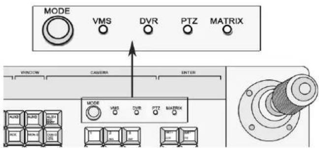
Figure 1-1 Mode Buttons
- DVR controlling: The keyboard can fulfill the complete function of the front panel operation of the DVR. And there are LED screen displays for all the operation. One keyboard can connect to 128 DVRs and the address code of the DVR ranges from 0 to 255.
- Analog Dome Controlling: The keyboard controls the PTZ function of the analog domes, the address code of the dome ranges from 0 to 255. A maximum 128 analog domes can be connected.
- VMS Controlling: The keyboard controls the video management platform, the TV wall switching and display, PTZ parameters setting and PTZ controlling.
● Analog Matrix Controlling: Control the signal input and output switch in the analog matrix.
Multiple Working Modes
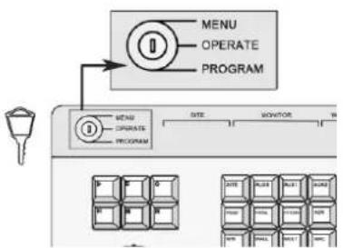
The working modes are chosen by turning the key on the front panel. See the figure below.
flowchart
graph TD
    A["MENU"] --> B["OPERATE"]
    B --> C["PROGRAM"]
    D["MENU"] --> E["OPERATE"]
    E --> F["PROGRAM"]
    G["SITE"] --> H["MONITOR"]
    I["DATA"] --> J["DATA"]
    K["REDACT"] --> L["REDACT"]
    M["DATA"] --> N["DATA"]
    O["REDACT"] --> P["REDACT"]
Figure 1-2 Turning the Key to Change Working Mode
- MENU: Keyboard Configuration Mode. Turn the key to the MENU. Set the keyboard parameters, such as the keyboard address, the RS-485 parameters and the RS-232 parameters.
- OPERATE: Keyboard Operation Mode. Turn the key to OPERATE. Under this mode, the keyboard can control the DVR, PTZ of the dome camera and the matrix.
- PROGRAM: Keyboard Function Settings Mode. Turn the key to PROGRAM. Under this mode, the keyboard can set the parameters for preset, pattern and patrol.
Protocols
There are 63 protocols of the PTZ control of dome camera, and the main protocols are HIKVISION, PELCO-P, PELCO-D,
SAMSUNG, YAAN-1, SONY, SIEMENS, DRAGON, NAIJIE, KALATEL, VICON and etc..
The control protocols for the analog matrix are ZT-1.0, ZT-2.0, EXTRON, and CREATOR.
Cascade Connection
DS-1004KI provides the cascade connection, and 16 auxiliary keyboards are connectable. The address of the auxiliary keyboard ranges from 0 to 255.
Other Features
- The keyboard can set different RS485 parameters such as the protocol and the Baudrate, which enables the flexible parallel connection to different devices.
● The convenient key locking function ensures the security of operation. - The keyboard integrates multiple control functions as the controlling of DVR, analog dome cameras and matrix. It can be used in the complex surveillance system.
- LED panel display is provided.
Chapter 2 Device Appearance
2.1 Rear Panel Description
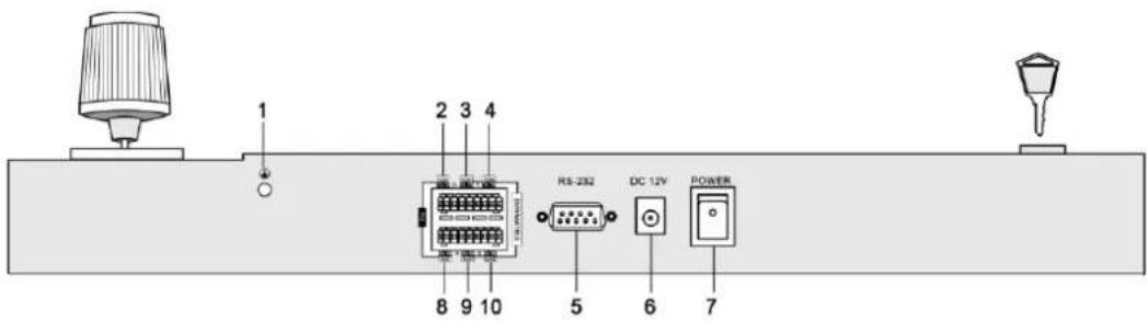
Figure 2-1 The Rear Panel of DS-1004KI Keyboard
Notes :
The green end with a G identifier on the rear panel is for grounding.
| Number | Physical Interfaces | Description |
| 1 | Grounding | The pillar for grounding. |
| 2 | PTZ-CON(PTZ Control Signal Output) | As main keyboard: Connect the dome camera or the RS485 of the PTZ: TA connects to RS485+, and TB connects to RS485-. As auxiliary keyboard: Connect the PTZ-AUX interface of the upper level keyboard: TA connects to RA and TB connects to RB. |
| 3 | DVR/MATRIX-CON1(DVR Control Signal Output) | As main keyboard: Connect the DVR KB interface; TA connects D+, TB connects D-; When connecting the RS-485 of the VMS: TA connects to the 6thpin and TB connects to 5thpin. When using the RS-485-to-RS-232 interface: TA connects to 4thpin and TB connects to 3rdpin.As auxiliary keyboard: Connect the AUX2 interface of the upper level keyboard.TA connects to RA and TB connects to RB. |
| 4 | DVR/MATRIX-CON2(Control Signal Output) | Output the RS-485 signal received by the 9thinterface identified in the figure above (AUX 1 interface). |
| 5 | RS232 Serial Interface | For the keyboard firmware upgrading and the control interface for the analog matrix. |
| 6 | Power Supply | 12VDC |
| 7 | Power Switch | Power on/ off |
| 8 | PTZ-AUX(Auxiliary keyboard PTZ control signal input) | Connect to the lower level PTZ-CON interface; RA connects to TA and RB connects to TB. |
| 9 | DVR/MATRIX-AUX1(Auxiliary keyboard DVR control signal input) | Connect a RS-485 signal source to receive the RS-485 signal. |
| 10 | DVR/MATRIX-AUX2(Auxiliary keyboard control signal input) | Connect to the DVR/MATRIX-CON interface of the lower level keyboard: RA connects to TA, RB connects to TB. |
We name the keyboard directly connecting the main keyboard upper level keyboard and we call the keyboard connecting to the upper level keyboard the lower level keyboard. For detailed information, see Chapter 2.4 for typical wiring methods.
2.2 Front Panel Description
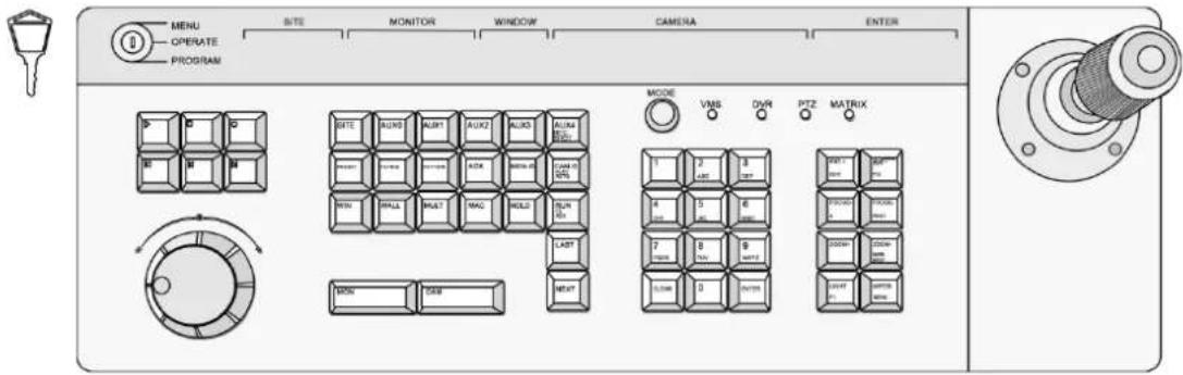
Figure 2-2 Top View on DS-1004KI Keyboard
Note:
Buttons on the keyboard have different functions in different controlling modes. For example, the IRIS+/EDIT button realizes the IRIS+ in PTZ control mode and in the DVR control mode, it is the EDIT button, when pressing, you can edit the combo field.
| Button | Description |
| Lock | Switch to change the working mode of the keyboard. |
| Playback Buttons | Reserved |
| Jog Shuttle Button | Reserved |
| SITE | Press this button to enter the DVR No., dome camera No., analog matrix No. or the VMS No.. |
| AUX0 | When controlling VMS, call the patrol of the dome camera. |
| AUX1 | Reserved |
| AUX2 | Reserved |
| AUX3 | Reserved |
| AUX4/ REC/SHOT | DVR control mode: Audio on/ off and |
| PRESET | Set and call the preset |
| PATROL | Set and call the patrol |
| PATTERN | Set and call the pattern |
| ACK | Reserved |
| MON-G | When controlling VMS, choose the monitor group. |
| CAM-G/PLAY/AUTO | When controlling VMS, choose the camera group. |
| DVR control mode: Fast play when playing back. | |
| WIN | When controlling VMS, press the button to choose windows. |
| WALL | When controlling VMS, select the TV wall after montage is done. |
| MULT | When controlling VMS, select the small screen which has not been montaged. |
| MAC | Reserved |
| HOLD | Stop cycling |
| RUN/F2/AUX | Start or Go on the cyclingDVR control mode: change the tab menu |
| NEXT | The next item, can be a channel or menu setting field. |
| LAST | The previous item, can be a channel or menu setting field. |
| MON | When controlling the VMS or analog matrix, press this button to choose the monitor. |
| CAM | When controlling the VMS or analog matrix, press this button to choose the camera. |
| MODE | Press to switch the control mode of the keyboard |
| Numeric & characters buttons (0-9) | Input the number or character; choose the live view or playback channel. |
| CLEAR | Clear the numbers input and exit. |
| ENTER | Enter |
| IRIS+/EDIT | PTZ control mode: iris+ |
| DVR control mode: enable editing | |
| IRIS-/PTZ | PTZ control mode: iris- |
| DVR control mode: show the PTZ control menu | |
| FOCUS+/A | PTZ control mode: focus+ |
| DVR control mode: switch the input methods | |
| FOCUS-/PREV | PTZ control mode: focus- |
| DVR control mode: switch the screen display. | |
| ZOOM+ | PTZ control mode: zoom+ |
| ZOOM-/ MAIN/SPOT | PTZ control mode: zoom- |
| DVR control mode: switch between main and auxiliary mode | |
| LIGHT/F1 | PTZ control mode: turn on the light |
| WIPER/MENU | PTZ control mode: enable wiper |
| DVR control mode: open the main men |
2.3 Joystick Function
| Graphic | Operation | Function |
 | Up | PTZ control mode: Move the PTZ up. |
| DVR control mode: Fast Play when playback, or navigate to the previous item when operating the menu. | ||
 | Down | PTZ control mode: Move the PTZ down. |
| DVR control mode: Slow play when playback, or navigate to the next item when operating the menu. | ||
 | Left | PTZ control mode: Move the PTZ to the left. |
| DVR control mode: Skip backward when playback, or navigate to the previous menu when operating the menu. | ||
 | Right | PTZ control mode: Move the PTZ right. |
| DVR control mode: Skip forward when playback, or navigate to the next menu when operating the menu. | ||
 | Left Rotate | Zoom in |
 | Right Rotate | Zoom out |
Notes :
The joystick realizes pan and tilt movement at 8 directions.
The 4-axis joystick can be used to control the zoom; and the central button used as Enter button and to realize picture capture as well.
2.4 Typical Wiring Methods
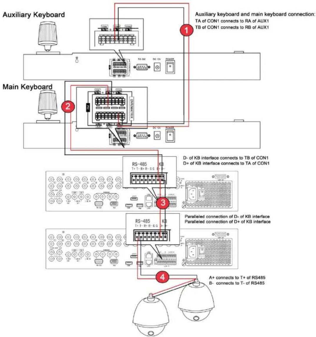
Figure 2-3 Connection between the keyboards, the keyboards and the dome camera, the keyboard and the DVRs
① shows the connection of the auxiliary keyboard and the main keyboard. You can connect many auxiliary keyboards to the main keyboard.
② shows the connection between the keyboard and the DVR/NVR.
③ shows the connection of DVRs when they are all connected and controlled by the keyboard.
④ shows the connection between DVR and dome cameras.
flowchart
graph TD
    A["Auxiliary Keyboard"] -->|1| B["Auxiliary keyboard and main keyboard connection: TA of CON connects to RA of AUX\nTB of CON connects to RB of AUX"]
    C["Main Keyboard"] -->|2| D["Auxiliary keyboard and main keyboard connection: TA of CON connects to RA of AUX\nTB of CON connects to RB of AUX"]
    E["Main Keyboard"] -->|3| F["Paralleled connection of A+ and B-"]
    style A fill:#f9f,stroke:#333
    style C fill:#f9f,stroke:#333
    style E fill:#f9f,stroke:#333
    style F fill:#ccf,stroke:#333
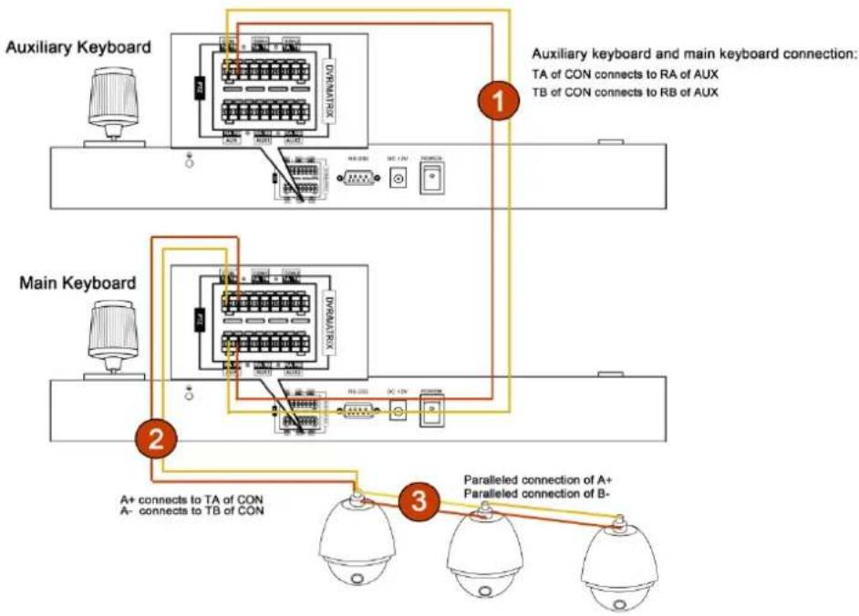
Figure 2-4 Connection between the main and auxiliary keyboards, and the keyboards and the dome camera
① shows the connection of the auxiliary keyboard and the main keyboard. You can connect many auxiliary keyboards to the main keyboard.
② shows the connection between keyboard and dome camera.
③ shows the connection between dome cameras when they are all connected and controlled by the keyboard.
flowchart
graph TD
    A["Paralleled Keyboard 1"] --> B["1"]
    A --> C["2"]
    A --> D["3"]
    A --> E["4"]
    A --> F["5"]
    G["Paralleled Keyboard 2"] --> H["3"]
    G --> I["4"]
    G --> J["5"]
    K["A+ connects to TA of CON\nB- connects to TB of CON"] --> L["RS-485 T+T-B+B-G"]
    M["Paralleled connection(A+)\nParalleled connection (B-)"] --> N["RS-485 T+T-B+B-G"]
    O["A+ connects to T+ of RS485\nB- connects to T- of RS485"] --> P["RS-485 T+T-B+B-G"]
    Q["D- of KB interface connects to TB of CON1\nD+ of KB interface connects to TA of CON1"] --> R["RS-485 T+T-B+B-G"]
    S["Paralleled connection of D- of KB interface\nParalleled connection of D+ of KB interface"] --> T["RS-485 T+T-B+B-G"]
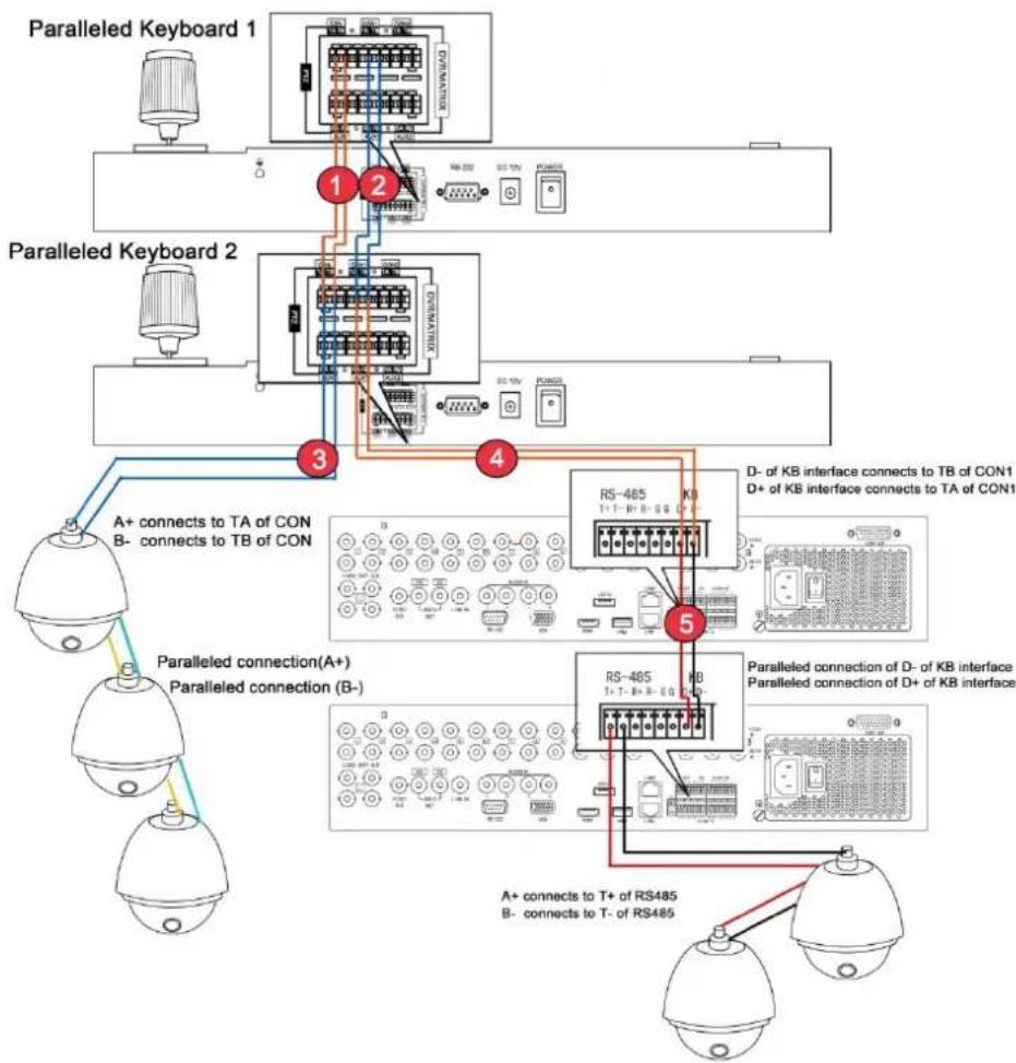
Figure 2-5 Connection between the paralleled keyboards, the keyboards and the dome camera, the keyboard and the DVRs
① shows the connection of keyboard when they are connected to each other to control the dome camera. PTZ-CON interface: TA connects TA, TB connects TB.
③ shows the connection between the keyboard and the dome camera. PTZ-CON TA connects 485+, TB connects 485-.
② shows the connection between the paralleled connected keyboard and DVR/NVR. DVR-CON: TA connects TA and TB connects TB.
④ shows the connection between the keyboard and DVR/NVR. DVR-CON1 TA connects D+ of KB and DVR-CON1 TB connects D- of KB.
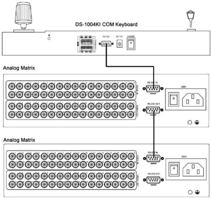
Figure 2-6 Connection between the keyboard and the analog matrix
The RS-232 interface of the DS-1004K1 keyboard uses the DB9 interface. And the definition of pins of DB9 interface is written in the table below.
| No. | Name | Function |
| 1 | DCD | -- |
| 2 | RXD | Receiving Data |
| 3 | TXD | Transmitting Data |
| 4 | DTR | -- |
| 5 | GND | Grounding |
| 6 | DSR | -- |
| 7 | RTS | -- |
| 8 | CTS | -- |
| 9 | RI | -- |
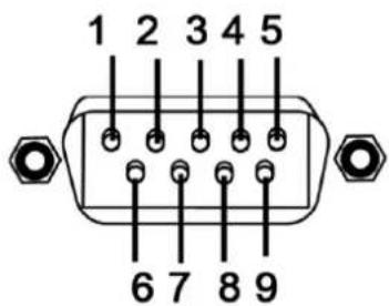
The DS-1004KI keyboard uses RS-232 interface, the RS-232 interface connects the keyboard control interface on the analog matrix.
The above figure shows the connection between keyboard and the analog matrix via RS-232 interface.
When connecting to more than one analog matrix, the analog matrix connected in parallel, showing in the above figure.
Note:
When controlling more than one analog matrix, the protocol is the ZT-1.0. Otherwise the cascading matrix cannot be controlled.
![MVC POWER SWAP LWR STATUS LAN RA-232 RS-232 85 LAN RA- Keyboard RS-232 DC 12V POWER RS-485 Cable PIN 6 of the RS-485 cable connects to TA of CON1 PIN 5 of the RS-485 cable connects to TB of CON1 The PIN number from the top down is [1~8].](/content/2026/05/921222/images/2770443bf269efd5ab94452eef21eb9b781d8d6801096a5feac2deb443755531.jpg)
Figure 2-7 Connection between the keyboard and the VMS
The DS-1004KI keyboard controls the VMS, and to control it, you need to configure the VMS with the cascading configuration tool. Please refer to the manual of the VMS.
The DVR-CON TA connects the sixth pin of RS-485 interface on the VMS side, and the DVR-CON TB connects the fifth pin of RS-485 interface on the VMS side.
Chapter 3 Keyboard Operation
3.1 Controlling DVR by Keyboard
Setting the Keyboard Parameters to Control DVR
Once the keyboard is connected to the DVR, it can be used just as the front panel of the DVR. The joystick can move the cursor.
Before you start:
Check the connection between the DVR and the Keyboard.
TA and TB of CON1 on the keyboard connect to D+ and D- of the DVR. The following figure shows the simplest way of connection between a DVR and keyboard.
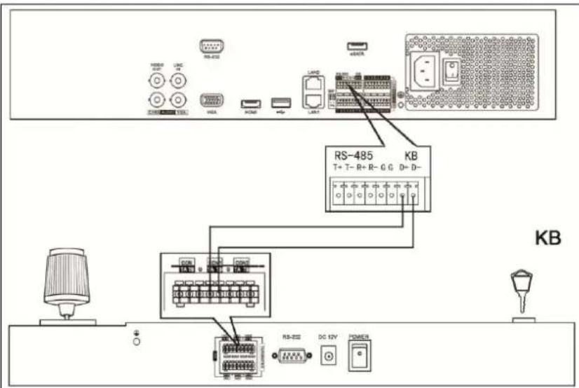
Figure 3-1 A Simple Connection between Keyboard and DVR
Steps:
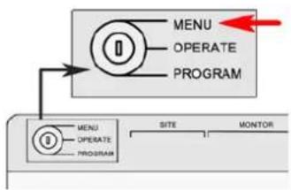
- On the keyboard, turn the key to the MENU item, and press the Mode button to select the DVR as the controlled device.
flowchart
graph TD
    A["MENU"] --> B["OPERATE"]
    A --> C["PROGRAM"]
    D["MENU"] --> E["OPERATE"]
    D --> F["PROGRAM"]
    G["SITE"] --> H["MONITOR"]
Figure 3-2 Turn the key to MENU
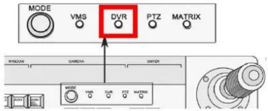
Figure 3-3 Choose MODE as DVR
- Press the numeric button and press SITE to connect the DVR.
Note: The keyboard identifies the DVR by SITE value, and the SITE value must be exactly the same with the device number. E.g. the device number is 1, press the numeric button 1 and press SITE button again.
The keyboard only connects the DVR with device number ranging from 1 to 255.
- You can move the joystick up and down to choose value and move the joystick left and right to switch the parameter to configure. The RS-485 parameters should be exactly the same with those of the DVR you controlled. The parameters include the baud rate, data bit, stop bit, and parity.
By default, the baud rate is 9600, the data bit is 8, the stop bit is 1 and the parity is none.
- When the LED screen shows COPYALL, you can move the joystick to choose YES or NO.
If you choose YES, those parameters such as baud rate you set will be copied to all the DVRs you controlled by the keyboard.
- Press Enter button to confirm your settings.
Now you can turn the key to the OPERATE item to control the DVR.
Operating DVR by Keyboard
The keyboard, once connected, functions as the front panel of the DVR. You can refer to the front panel button description to see the function of each button. See the below information for complicated operation.
Before you start:
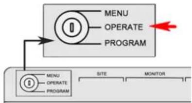
To control DVR, make sure that the key is turned to the OPERATE mode.
flowchart
graph TD
    A["MENU"] --> B["OPERATE"]
    B --> C["PROGRAM"]
    D["MENU"] --> E["OPERATE"]
    E --> F["PROGRAM"]
    G["SITE"] --> H["MONITOR"]
Figure 3-4 Turn the Key to OPERATE
- In live view mode, press numeric button to enter the corresponding one-channel live view. The NEXT and LAST button to choose the next or previous channel. When you open the menu, the NEXT and LAST button can be used to select the next or previous item.
- In the OPERATE mode the PLAY/AUTO button functions as the PLAY/AUTO button on the DVR front panel. Press it to play the record file within the 5 minutes of current channel. If you want to play back more record files, you should enter the main menu and choose Playback.
• CLEAR button functions as an ESC button
To call the preset/patrol/pattern:
Steps:
- Press IRIS-/PTZ button to enter the PTZ control interface of the DVR
- Press the PRESET/PATROL/PATTERN button.
- Press the numeric button.
- Press ENTER button.
3.2 Controlling Dome Cameras by Keyboard
Setting the Keyboard Parameters to Control Dome Camera
Before you start:
Check the connection between the keyboard and dome camera. The TA and TB interfaces of CON of keyboard should be connected to the RA and RB interfaces of the dome camera respectively. The following figure shows the simplest way of connection between a dome camera and keyboard.
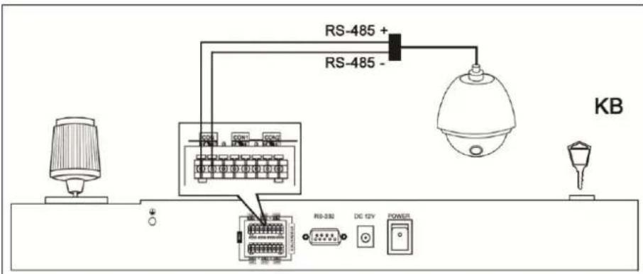
Figure 3-5 Dome and Keyboard Connection
Steps:
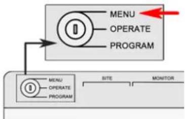
- Turn the key to the MENU item, and press the Mode button to select PTZ.
flowchart
graph TD
    A["MENU"] --> B["PROGRAM"]
    C["MENU"] --> D["PROGRAM"]
    E["SITE"] --> F["MONITOR"]
Figure 3-6 Turning the Key to MENU
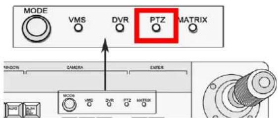
Figure 3-7 Choose Mode as PTZ
- Enter the device number. E.g. the device number is 1, press the numeric button 1 and press SITE button again.
Note: The keyboard identifies the dome camera by SITE value, and the SITE value must be exactly the same with the dome camera No..
- Use the joystick to set the RS485 parameters.
Hikvision
The parameters include the protocol, baud rate, data bit, stop bit, and parity.
- When the LED screen shows COPYALL, you can choose YES or NO.
When you choose YES, the parameters you just set will be copied to other dome cameras connected.
-
Press Enter button to confirm your settings.
-
Turn the key to the OPERATE item to control the dome camera.
Dome Camera Control Operation
The keyboard mainly controls the PTZ function of the dome camera. The PTZ function of the dome camera is realized by the compound operation of the joystick and the PTZ buttons.
- To call the preset, switch to the OPERATE mode, press PTZ button to enter PTZ control mode and press the numeric button and then press the preset button.
Note: Call preset No. 95 to open the menu of the dome camera.
• To call patrol, switch to the OPERATE mode, press the numeric button and then press the patrol button;
• To call pattern, switch to the OPERATE mode, press the numeric button and then press the pattern button.
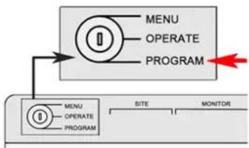
To set preset, patrol and pattern for the dome camera, you turn the key to the PROGRAM mode
flowchart
graph TD
    A["MENU"] --> B["PROGRAM"]
    C["MENU"] --> D["PROGRAM"]
    E["SITE"] --> F["MONITOR"]
Figure 3-8 Turn the Key to PROGRAM
Setting the preset
Press the numeric button and then press the preset button.
And the LED screen returns PRESET DONE, indicating that the preset is set.
Setting the patrol:
Note: the patrol is a group of presets.
Steps:
- In the PROGRAM mode. Press the numeric button and press the PATROL button.
And then you can see the LED screen shows PATROL SET. - Press numeric button and press Enter button to choose the preset for the patrol.
- Press the numeric button again and press Enter button again to set the patrol time.
- Press the numeric button and press Enter button to set the patrol speed.
- Press the PATROL button to finish the setting.
And the LED screen returns PATROL DONE, indicating that the patrol is set.
Setting the pattern:
Steps:
- Switch to the PROGRAM mode.
- Press the numeric button and press the pattern button.
- Use the joystick and ZOOM+/- button to control the PTZ and record the PTZ movement.
- Press the PATTERN button again to set the pattern.
Hikvision
3.3 Controlling the VMS by Keyboard
Setting the Keyboard Parameters to Control VMS
There is no RS485 interface for the VMS, you can use the RS-485-to-RS-232 converter to connect the VMS.
- Turn the key to the MENU item, and press the Mode button to select the Matrix as the controlled device.
- Press the SITE button to set the device identifier.
Note: The keyboard identifies the controlled device by the device address. You can set the SITE value to identify the device, and the SITE value must be exactly the same with the VMS address.
- Enter the number. E.g. the device address is 1, press the numeric button 1 and press SITE button again.
- Use the joystick to set the RS485 parameters.
The parameters include the baud rate, data bit, stop bit, and parity.
- When the LED screen shows COPYALL, you can use the joystick to choose YES or NO.
- Press Enter button to confirm your settings.
- Turn the key to the OPERATE item to control the VMS.
VMS Control Operation
Note:
When using DS-1004KI to control the VMS, the parameters of the keyboard should be consistent to that of the VMS software and the VMS should be configured by the cascade configuration tools. For the detailed information of the configuration, refer to the user manual of the VMS. And since there is no RS-485 interface for VMS, you need to choose the RS-485-to-RS-232 interface as RS-485. The monitor in this chapter refers to the single monitor without montaging. Sub-screen refers to the small screens in single monitor.
Complicated Operation:
- Press the numeric button and then press the MON button to select the video output monitor.
- Press the numeric button and then press CAM button to choose video input channel.
- Press the numeric button and press MULT button to set the sub-screen. Press the numeric button and the WIN button to choose the sub-screen.
Example:
To set 4 sub-screens to the monitor 1 and display the video from camera 1 to the second window:
Steps:
- Press numeric button 1 and press MON button.
- Press numeric button 4 and press MULT button.
- Press numeric button 2 and press WIN button.
- Press numeric button 1 and press CAM button.
The monitor group and the camera group refer to the video output group and video input group respectively. When displaying the video from one camera group on one monitor, the cycle play function can be enabled. HOLD button can stop the cycle play and the RUN button can start or go on the cycle play. NEXT and LAST button can be used to switch to the next group or last group respectively.
Example:
To display the camera group 2 on the monitor 1 to cycle play and then stop cycle play and then go on the cycle play, and then switch to the camera group 1.
Steps:
- Press numeric button 1 and press MON.
- Press numeric button 2 and press CAM-G button.
- Press HOLD button.
- Press RUN button.
-
Press LAST button.
-
To set the preset, turn the key to the PROGRAM mode, press the numeric button and press CAM button to choose camera. Press numeric button and press preset button the set preset.
- To call the preset, switch to the OPERATE mode and press the numeric button and press CAM button to choose the camera.
Press the numeric button and press preset button to call the preset.
Setting the patrol:
Steps:
- Turn the key to PROGRAM mode, press the numeric and press CAM button to choose camera.
- Press the numeric button and press patrol button to choose patrol to set.
- Press the numeric button and ENTER button to call the preset you want to add to the patrol.
- Press the numeric button and the ENTER button to set the interval for patrol.
- Press the numeric button and ENTER button to set patrol speed.
- Press patrol button again to finish your setting.
Calling the patrol:
Steps:
- Turn the key to the OPERATE mode, press the numeric button and press CAM button to choose camera.
- Press the numeric button and press patrol button to call the patrol.
Setting the pattern,
Steps:
- Switch to the PROGRAM mode, and press the numeric button and press the CAM button to choose camera.
- Press the numeric button and press the pattern button
- Use the joystick to control the PTZ to record the PTZ movement.
- Press the pattern button again to set the pattern.
- To call the pattern, switch to the OPERATE mode, press the numeric button and press CAM button to choose camera.
- Press the numeric button and press pattern to call the pattern.
3.4 Controlling the Analog Matrix by Keyboard
Setting the Keyboard Parameters to Control Analog Matrix
The RS-232 communication is used when the DS-1004KI keyboard is controlling the analog matrix system. And the following parameters must be correctly configured for the RS-232 port: protocol, baud rate, data bit, stop bit and parity. ZT-1.0, ZT-2.0, EXTRON and CREATOR protocols are supported by the keyboard.
Turn the key to MENU; press the SITE button to select the address for analog matrix to be configured; and set the RS-232 parameters.
To set the RS-232 parameters:
Steps:
- Move the joystick left/right to view selections.
- Move the joystick up/down to select a parameter.
- Move the joystick up/down to select YES in the COPYALL selection if you want to copy the settings to all the other devices. The default setting is NO.
- Turn the key to Operate to operate the device remotely.
Analog Matrix Controlling Operation
Main Operation:
• Use the SITE button to choose the analog matrix by its address.
• To display the video from a camera to a certain monitor.
In the OPERATE mode, press the numeric button and the press the MON button to choose the video output monitor. Press the numeric button and press CAM button.
• Use the NEXT button and the LAST button to realize the switch of the video input.
• Use CLEAR button to delete the number you input or exit the operation.
Appendix 1: Specification
| Model | DS-1004KI |
| Joystick | Four-Axis |
| Serial Port | RS485 and RS232 |
| Working Temperature | -10°C-+55°C |
| Working Humidity | 10%-90% |
| Power Supply | 12VDC |
| Power Consumption | ≤10W |
| Dimension (W×D×H) | 434×163×43mm |
| Weight | ≤1.25Kg |
First Choice for Security Professionals
- User Manual of DS-1004KI Keyboard
- Preventive and Cautionary Tips
- Contents
- Chapter 1 Product Overview
- Multiple Controlling Modes
- Multiple Working Modes
- Protocols
- Cascade Connection
- Other Features
- Chapter 2 Device Appearance
- Rear Panel Description
- Notes :
- Front Panel Description
- Note:
- Joystick Function
- Typical Wiring Methods
- Chapter 3 Keyboard Operation
- Controlling DVR by Keyboard
- Setting the Keyboard Parameters to Control DVR
- Before you start:
- Steps:
- Operating DVR by Keyboard
- To call the preset/patrol/pattern:
- Controlling Dome Cameras by Keyboard
- Setting the Keyboard Parameters to Control Dome Camera
- Dome Camera Control Operation
- Setting the preset
- Setting the patrol:
- Setting the pattern:
- Controlling the VMS by Keyboard
- Setting the Keyboard Parameters to Control VMS
- VMS Control Operation
- Complicated Operation:
- Example:
- Calling the patrol:
- Setting the pattern,
- Controlling the Analog Matrix by Keyboard
- Setting the Keyboard Parameters to Control Analog Matrix
- To set the RS-232 parameters:
- Analog Matrix Controlling Operation
- Main Operation:
- Appendix 1: Specification
- First Choice for Security Professionals
Brand : Hikvision
Model : DS-1004KI
Category : Keyboard