
TC-400R8A - Computer Adapter Fantec - Free user manual and instructions
Find the device manual for free TC-400R8A Fantec in PDF.


| Product Type | Dual AC Mini Redundant Power Supply |
| Model | TC-400R8A |
| Brand | Fantec |
| Input Voltage | 90-132 VAC or 180-264 VAC auto-selectable, 47-63 Hz |
| Output Power per Module | 400W maximum |
| Output Voltages | +5V, +12V, +3.3V, -12V, -5V, +5Vsb |
| Max Loads | +5V: 35A, +12V: 18A, +3.3V: 24A, -12V: 0.8A, -5V: 0.5A, +5Vsb: 2A |
| Combined Power Limits | +5V & +3.3V ≤ 175W; +5V, +12V & +3.3V ≤ 375W |
| Regulation | ±5% for +5V, +12V, +3.3V, +5Vsb; ±10% for -12V, -5V |
| Ripple & Noise | +5V: 50 mV, +12V: 120 mV, +3.3V: 50 mV, -12V: 120 mV, -5V: 50 mV, +5Vsb: 50 mV |
| Efficiency | ≥67% at full load |
| Hold-Up Time | 16 ms at maximum load and normal input voltage |
| Protections | Over Voltage (+5V set at 6.25V ±0.75V), Short Circuit, Over Power (130-160%) |
| Operating Temperature | 0°C to 50°C |
| Storage Temperature | -20°C to 70°C |
| Humidity | 5% to 90% non-condensing |
| Cooling | Forced air |
| MTBF | 100,000 hours at full load and 25°C ambient |
| Fan Life Expectancy | 40,000 hours at 40°C |
| Agency Approvals | UL 1950, TUV Rheinland (EN60950, IEC950 mod), CB Certification |
| EMI/RFI Compliance | FCC Part 15 Class B, EN55022 Class B, EN61000-3-3 |
| Key Features | Hot-Swap, Power Sharing, Dual AC Input, Hot-Pluggable, Auto-select AC, Buzzer and LED alarms |
| Dimensions (L x W x H) | 200 mm x 150 mm x 86 mm |
| Connectors | 7x 5.25", 1x 3.5", 1x ATX 24/20-pin, 1x 8-pin, 1x +12V Power Connector |
Frequently Asked Questions - TC-400R8A Fantec
User questions about TC-400R8A Fantec
0 question about this device. Answer the ones you know or ask your own.
Ask a new question about this device
Download the instructions for your Computer Adapter in PDF format for free! Find your manual TC-400R8A - Fantec and take your electronic device back in hand. On this page are published all the documents necessary for the use of your device. TC-400R8A by Fantec.
USER MANUAL TC-400R8A Fantec
Dual AC Mini Redundant Power Supply
400W+400W
for IPC-Computer
Model No. TC-400R8A
Table of content
- Introduction......1
2. Specification
2.1 Input Voltage....1
2.2 DC Output....1
2.3 PS-ON (Remote ON/OFF).....2
2.4 PW-OK(power good signal)....2
2.5 Efficiency....2
2.6 Hold-Up Time....2
3. PROTECTION
3.1 Over Voltage protection....2
3.2 Short Circuit Protection....2
3.3 Over Power Protection....3
3.4 No Load operation....3
-
Environment Temperature....3
-
Reliability....3
-
Agency approvals....3
-
EMI/RFI....3
-
Instructions....3
-
HOT-SWAP Procedures....4
-
PINOUTS of connectors....4
Color Reference for LED cable....4
Main Power Connector....5
- Dimension....5
1. Introduction
The 400R8A Series products of Hot-Swap & Power Sharing redundant Power supply provides increased reliability when integrated a variety of Systems. The 400R8A series is ideally suited to telecommunications and Industrial system, as well as a variety of other applications where system Never shut down i. E. Zero down time.
TC-400R8A series redundant power supply, it consists of
§ One of passive Back plane.
‡ One of exothermal enclosure.
Two of compact size power modules with Hot-Pluggable connector made by Germany.
‡ Screw package.
* Alarm reset bottom.
Features
Dual AC IN-Put design. AC-1 be Master source, AC-2 be second source.
Dual AC PANTEN. Taiwan, USA, Germany, China
* PS/2 Size design.
Hot-Swappable & Power Sharing capability. ( Patent no. 136053 )
§ Auto Select AC input.
2. Specification
2.1 AC Input Voltage:90 to 132 or 180 to 264 auto selectable 47Hz \~ 63 Hz.
2.2 DC Output: 400W maximum
| VOLTAGE | +5V | +12V | +3.3V | -12V | -5V | +5Vsb |
| MAX. LOAD | 35A | 18A | 24A | 0.8A | 0.5A | 2A |
| MIN. LOAD | 3A | 2A | 0.3A | 0.1A | 0.1A | 0.1A |
| REGULATION | ± 5% | ± 5% | ± 5% | ± 10% | ± 10% | ± 5% |
| RIPPLE(mV) | 50 | 120 | 50 | 120 | 50 | 50 |
Note:
- The combined total power from +5V and +3.3V shall not exceed 175W. The combined total power from +5V and +12V & +3.3V shall not exceed 375W
- Noise Test - Noise bandwidth is from DC to 20 MHz.
- Ripple frequencies greater than 1MHz shall be attenuated by the measurement System.
- Add 0.1uF/10uF capacitor at output connector terminals for ripple and noise measurements.
2.3 PS-ON
Remote On/Off Control:
When PS-ON is pulled to TTL Low, the DC output is to be enabled.
When PS-OFF is pulled to TTL high, the DC output is to be disabled.
2.4 PW-OK
PW-OK is power good signal and should be asserted high by the power supply to indicate that +5VDC and +3.3VDC output are above the under voltage thresholds of the power supply TTL. compatible signal out with 100ms to 500ms.
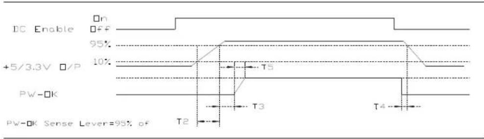
Timing of PS-ON, PW-OK, and Germane Voltage Rails
Although there is no requirement to meet specific timing parameters, The following signal timings are recommended:
2ms≤ T2≤ 200ms
100ms≤ T3≤ 500ms
T4>1ms
T5≤10ms
2.5 Efficiency: ≥ 67% at full load. (Normal Line)
2.6 Hold-Up Time: 16ms at maximum load & normal input voltage.
3.PROTECTIONS
3.1 OVER-VOLTAGE PROTECTION
Standard on +5.0V output, set at 6.25VDC ± 075VDC.
3.2 SHORT CIRCUIT PROTECTION
A short circuit placed between the DC Return and the output shall cause No damage and the power supply shall shutdown.
3.3 OVER POWER PROTECTION
The power supply shall shut down when output power exceeds 130% to 160% of full load and require a power on cycle be performed by the operate
No parts shall be damaged on the power supply.
4. ENVIRONMENT TEMPERATURE
4.1 Operation Temperature: 0°C to 50°C
4.2 Cooling: By forced air
4.3 Storage Temperature: -20°C to 70°C
4.4 Humidity: 5 to 90% non-condensing.
5. RELIABILITY
5.1 MTBF OF POWER SUPPLY ELECTRONIS
100,000 hours at full load and 25^ C ambient temperature
5.2 LIFE EXPECTANCY OF FAN
40,000 hours at 40^ C
6. AGENCY APPROVALS
UL 1950 QQGQ2
UL 1950 QQGQ8
TUV Rheinland (EN60950, IEC950 mod)
CB Certification
7. EMI /RFI
FCC part 15, Subpart B, Class B
EN55022 CISPR22 Class B, CE Make
EN61000-3-3;1995
The set still works properly even if either unit is removed. The removed unit can't be used in other machinery nor for other purpose. When one unit breaks down, it's LED will blink, buzzer will sound. Push the Reset button and buzzer will stop.
REDUNDANCY
Offer redundant function for power system and mutually backs up the outputs. A zero transfer time when backup takes place.
HOT-SWAP
The power system provides a Hot-Swap function. This means when either one of the redundant power supplies fails or breaks down, you can easily replace failed unit without any interference to the system.
BUZZER
A warning buzzer sounds when any one of the power supplies fails. The warning buzzer is reset table from reset switch either the one in front control panel or the one on the rear side.
LED'S
The warning LED'S can be found either on the rear side or the control panel of the power system. Tells if one of the two power supplies has failed, by LED blinking.
HOT-PLUGGABLE
The power system provides a Hot-Pluggable function This method allows the power units in the Disk Array/File Server to be removed or inserted very easily without
9.HOT-SWAP PROCEDURES
Please refer to the followings when either one power supply unit is fount defective.
A) Locate the defective power supply by examining the individual LED on the power unit or the LED on the front control panel if LED is Blinking.
B) Unlock & Remove the defective power supply unit.
C) Replace a new GOOD power supply unit, Insert the power supply into the power system chassis in position & it will auto Lock-up.
D) Turn on the new power supply unit.
E) Check the module LED which indicate the power and LED of total power system status, Both LED shall Have steady life.
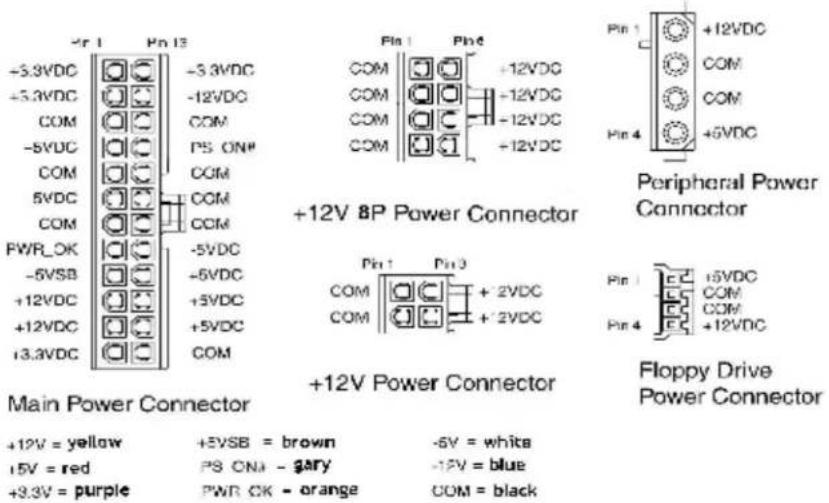
10.PINOUTS OF CONNECTORS
7x 5.25", 1 x 3.5", 1 x ATX-24Pin or 20Pin(for motherboard), 1 x 8Pin Power Connector 1 x +12V Power Connector
\* Color Reference for LED cable
POWER: 1 LED Cable
Brown / with
POWER: 2 LED Cable
Red / with
MAIN POWER LED Cable
Green / with
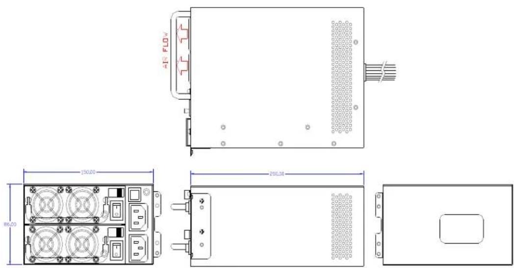
11.DIMENSION
TC-XXXR8A L 200 x W150 x H 86 mm
- Dual AC Mini Redundant Power Supply
- for IPC-Computer
- Table of content
- Specification
- PROTECTION
- Introduction
- TC-400R8A series redundant power supply, it consists of
- Note:
- PS-ON
- Remote On/Off Control:
- PW-OK
- 3.PROTECTIONS
- OVER POWER PROTECTION
- ENVIRONMENT TEMPERATURE
- RELIABILITY
- MTBF OF POWER SUPPLY ELECTRONIS
- LIFE EXPECTANCY OF FAN
- AGENCY APPROVALS
- EMI /RFI
- BUZZER
- LED'S
- HOT-PLUGGABLE
- 9.HOT-SWAP PROCEDURES
- 10.PINOUTS OF CONNECTORS
- \* Color Reference for LED cable
- 11.DIMENSION
Brand : Fantec
Model : TC-400R8A
Category : Computer Adapter