
Pro 6305 SFF - Desktop computer COMPAQ - Free user manual and instructions
Find the device manual for free Pro 6305 SFF COMPAQ in PDF.


| Product Type | Desktop Computer |
| Brand | Compaq (HP) |
| Model | Pro 6305 SFF |
| Form Factor | Small Form Factor (SFF) |
| Processor | AMD A-Series APU (e.g., A6-5400B dual-core up to 3.6 GHz) |
| Memory (Max) | 16 GB DDR3 SDRAM (2 slots) |
| Storage | 500 GB SATA HDD (optional SSD upgrade) |
| Graphics | Integrated AMD Radeon HD 8000 Series |
| Operating System | Windows 7 Professional (or Windows 8 Pro) |
| Power Supply | 240W internal power supply |
| Dimensions (W x D x H) | 10.5 x 3.9 x 13.3 in (26.7 x 9.9 x 33.8 cm) |
| Weight | Approx. 12.5 lbs (5.7 kg) |
| Front Ports | 2x USB 2.0, 1x USB 3.0, headphone/mic jacks |
| Rear Ports | 4x USB 2.0, 2x USB 3.0, VGA, DisplayPort, RJ-45 Ethernet, audio out |
| Expansion Slots | 1x PCIe x16, 1x PCIe x1, 1x M.2 (optional) |
| Security Features | Kensington lock slot, power-on password, setup password |
| Cooling System | Active cooling with fan and vented chassis |
| Maintenance | Tool-less access to interior, easy RAM/HDD upgrades |
| Recommended Use | Business, home office, general productivity |
| Color | Black with silver accents |
Frequently Asked Questions - Pro 6305 SFF COMPAQ
User questions about Pro 6305 SFF COMPAQ
0 question about this device. Answer the ones you know or ask your own.
Ask a new question about this device
Download the instructions for your Desktop computer in PDF format for free! Find your manual Pro 6305 SFF - COMPAQ and take your electronic device back in hand. On this page are published all the documents necessary for the use of your device. Pro 6305 SFF by COMPAQ.
USER MANUAL Pro 6305 SFF COMPAQ
HP Compaq Business PC Hardware Reference Guide
Pro 6300 Series Microtower Pro 6300 Series Small Form Factor
© Copyright 2012 Hewlett-Packard Development Company, L.P. The information contained herein is subject to change without notice.
Microsoft, Windows, and Windows Vista are either trademarks or registered trademarks of Microsoft Corporation in the United States and/or other countries.
The only warranties for HP products and services are set forth in the express warranty statements accompanying such products and services. Nothing herein should be construed as constituting an additional warranty. HP shall not be liable for technical or editorial errors or omissions contained herein.
This document contains proprietary information that is protected by copyright. No part of this document may be photocopied, reproduced, or translated to another language without the prior written consent of Hewlett-Packard Company.
HP Compaq Business PC Hardware Reference Guide
Pro 6300 Series Microtower
Pro 6300 Series Small Form Factor
First Edition (March 2012)
Document part number: 686565-001
About This Book
This guide provides basic information for upgrading HP Compaq Business PCs.
WARNING! Text set off in this manner indicates that failure to follow directions could result in bodily harm or loss of life.
CAUTION: Text set off in this manner indicates that failure to follow directions could result in damage to equipment or loss of information.
NOTE: Text set off in this manner provides important supplemental information.
Table of contents
1 Product Features .... 1
Standard Configuration Features .... 1
Microtower (MT) Front Panel Components 2
Small Form Factor (SFF) Front Panel Components 3
Microtower (MT) Rear Panel Components 4
Small Form Factor (SFF) Rear Panel Components 5
Media Card Reader Components 6
Keyboard 7
Using the Windows Logo Key 8
Serial Number Location 9
2 Microtower (MT) Hardware Upgrades 11
Serviceability Features 11
Warnings and Cautions 11
Removing the Computer Access Panel 12
Replacing the Computer Access Panel 13
Removing the Front Bezel 14
Removing Bezel Blanks 14
Replacing the Front Bezel 15
System Board Connections 16
Installing Additional Memory 17
DIMMs 17
DDR3-SDRAM DIMMs 17
Populating DIMM Sockets 17
Installing DIMMs 18
Removing or Installing an Expansion Card 20
Drive Positions 24
Installing and Removing Drives 25
Removing a 5.25-inch or 3.5-inch Drive from a Drive Bay 27
Installing a 5.25-inch or 3.5-inch Drive into a Drive Bay 29
Removing a Hard Drive from a Drive Bay 32
Installing a Hard Drive into an Internal Drive Bay 33
Installing a Security Lock 37
Cable Lock 37
Padlock 37
HP Business PC Security Lock 38
Front Bezel Security 42
3 Small Form Factor (SFF) Hardware Upgrades 44
Serviceability Features 44
Warnings and Cautions 44
Removing the Computer Access Panel 45
Replacing the Computer Access Panel 46
Removing the Front Bezel 47
Removing Bezel Blanks 47
Replacing the Front Bezel 48
Changing from Desktop to Tower Configuration 49
System Board Connections 50
Installing Additional Memory 51
DIMMs 51
DDR3-SDRAM DIMMs 51
Populating DIMM Sockets 51
Installing DIMMs 52
Removing or Installing an Expansion Card 55
Drive Positions 59
Installing and Removing Drives 60
Removing a 5.25-inch Drive from a Drive Bay 62
Installing a 5.25-inch Drive into a Drive Bay 64
Removing a 3.5-inch Drive from a Drive Bay 67
Installing a 3.5-inch Drive into a Drive Bay 69
Removing and Replacing the Primary 3.5-inch Internal Hard Drive 71
Installing a Security Lock 75
Cable Lock 75
Padlock 75
HP Business PC Security Lock 76
Front Bezel Security 80
Appendix A Battery Replacement 82
Appendix B Removing and Replacing a Removable 3.5-inch SATA Hard Drive 85
Appendix C Unlocking the Smart Cover Lock 90
Smart Cover FailSafe Key 90
Using the Smart Cover FailSafe Key to Remove the Smart Cover Lock 90
Appendix D Electrostatic Discharge 92
Preventing Electrostatic Damage 92
Grounding Methods 92
Appendix E Computer Operating Guidelines, Routine Care and Shipping Preparation 93
Computer Operating Guidelines and Routine Care 93
Optical Drive Precautions 94
Operation 94
Cleaning 94
Safety 94
Shipping Preparation 94
Index 95
1 Product Features
Standard Configuration Features
Features may vary depending on the model. For a complete listing of the hardware and software installed in the computer, run the diagnostic utility (included on some computer models only).
Figure 1-1 Microtower Configuration
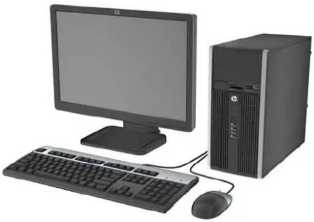
Figure 1-2 Small Form Factor Configuration


NOTE: The Small Form Factor computer can also be used in a tower orientation. For more information, see Changing from Desktop to Tower Configuration on page 49 in this guide.
Microtower (MT) Front Panel Components
Drive configuration may vary by model. Some models have a bezel blank covering one or more drive bays.
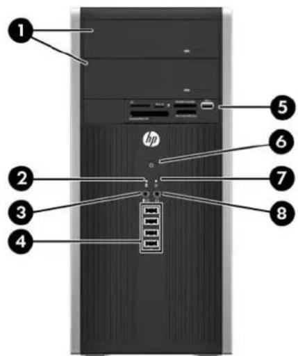
Table 1-1 Front Panel Components
| 1 5.25-inch Optical Drives 5 3.5-inch Media Card Reader (optional) |
| 2 Hard Drive Activity Light 6 Dual-State Power Button |
| 3 Microphone/Headphone Connector 7 Power On Light |
| 4 USB (Universal Serial Bus) 2.0 Ports 8 Headphone Connector |
| NOTE: When a device is plugged into the Microphone/Headphone Connector, a dialog box will pop up asking if you want to use the connector for a microphone Line-In device or a headphone. You can reconfigure the connector at any time by double-clicking the Realtek HD Audio Manager icon in the Windows taskbar. |
| NOTE: The Power On Light is normally green when the power is on. If it is flashing red, there is a problem with the computer and it is displaying a diagnostic code. Refer to the Maintenance and Service Guide to interpret the code. |
Small Form Factor (SFF) Front Panel Components
Drive configuration may vary by model. Some models have a bezel blank covering one or more drive bays.
Figure 1-3 Front Panel Components

Table 1-2 Front Panel Components
| 1 5.25-inch Optical Drive 5 Microphone/Headphone Connector |
| 2 Dual-State Power Button 6 3.5-inch Media Card Reader (optional) |
| 3 Power On Light 7 Hard Drive Activity Light |
| 4 USB (Universal Serial Bus) Ports 8 Headphone Connector |
| NOTE: When a device is plugged into the Microphone/Headphone Connector, a dialog box will pop up asking if you want to use the connector for a microphone Line-In device or a headphone. You can reconfigure the connector at any time by double-clicking the Realtek HD Audio Manager icon in the Windows taskbar. |
| NOTE: The Power On Light is normally green when the power is on. If it is flashing red, there is a problem with the computer and it is displaying a diagnostic code. Refer to the Maintenance and Service Guide to interpret the code. |
Microtower (MT) Rear Panel Components
Figure 1-4 Rear Panel Components

Table 1-3 Rear Panel Components
| 1 | Power | Cord | Connector | 6 | ←Line-Out Connector for powered audio devices (green) | |
| 2 | → | Line-In Audio Connector (blue) 7 PS/2 Keyboard Connector (purple) | ||||
| 3 | θ | PS/2 Mouse Connector (green) 8 VGA Monitor Connector | ||||
| 4 | IOIOIA | Serial Connector 9 DisplayPort Monitor Connector | ID | |||
| 5 | MΩ | RJ-45 Network Connector 10 USB 3.0 ports | ↔ | |||
| 11 | ↔ USB 2.0 ports | |||||
NOTE: An optional second serial port and an optional parallel port are available from HP.
When a device is plugged into the blue Line-In Audio Connector, a dialog box will pop up asking if you want to use the connector for a line-in device or a microphone. You can reconfigure the connector at any time by double-clicking the Realtek HD Audio Manager icon in the Windows taskbar.
The monitor connectors on the system board are inactive when a graphics card is installed in the computer.
If a graphics card is installed into one of the motherboard slots, the connectors on the graphics card and the system board may be used at the same time. Some settings may need to be changed in Computer Setup to use both connectors.
Small Form Factor (SFF) Rear Panel Components
Figure 1-5 Rear Panel Components

Table 1-4 Rear Panel Components
| 1 RJ-45 Network Connector 7 DisplayPort Monitor Connector | ||||||
| 2 | IOIOIA | Serial Connector 8 VGA Monitor Connector | ||||
| 3 | PS/2 Mouse Connector (green) 9 PS/2 Keyboard Connector (purple) | |||||
| 4 | Power | Cord | Connector | 10 | Line-Out Connector for powered audio devices (green) | |
| 5 | USB 2.0 ports | 11 Line-In Audio Connector (blue) | ||||
| 6 | USB 3.0 ports | |||||
NOTE: An optional second serial port and an optional parallel port are available from HP.
When a device is plugged into the blue Line-In Audio Connector, a dialog box will pop up asking if you want to use the connector for a line-in device or a microphone. You can reconfigure the connector at any time by double-clicking the Realtek HD Audio Manager icon in the Windows taskbar.
The monitor connectors on the system board are inactive when a graphics card is installed in the computer.
If a graphics card is installed into one of the motherboard slots, the connectors on the graphics card and the system board may be used at the same time. Some settings may need to be changed in Computer Setup to use both connectors.
Media Card Reader Components
The media card reader is an optional device available on some models only. Refer to the following illustration and table to identify the media card reader components.
Figure 1-6 Media Card Reader Components
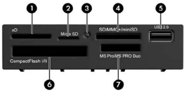
Table 1-5 Media Card Reader Components
| No. | Slot | Media | ||
| 1 xD | xD-Picture Card (xD) | |||
| 2 | MicroSD | MicroSD (T-Flash) | MicroSDHC | |
| 3 Media Card Reader Activity Light | ||||
| 4 | SD/MMC+/miniSD | Secure Digital (SD)Secure Digital High Capacity (SDHC)MiniSD | MiniSDHCMultiMediaCard (MMC)Reduced Size MultiMediaCard (RS MMC) | MultiMediaCard 4.0 (MMC Plus)Reduced Size MultiMediaCard 4.0 (MMC Mobile)MMC Micro (adapter required) |
| 5 USB • USB (Universal Serial Bus) Port | ||||
| 6 | CompactFlash I/II | CompactFlash Card Type 1 | CompactFlash Card Type 2 | MicroDrive |
| 7 | MS PRO/MS PRO DUO | Memory Stick (MS)MagicGate Memory Stick (MG)MagicGate Memory Duo | Memory Stick SelectMemory Stick Duo (MS Duo)Memory Stick PRO (MS PRO) | Memory Stick PRO Duo (MS PRO Duo)Memory Stick PRO-HG DuoMemory Stick Micro (M2) (adapter required) |
Keyboard
Figure 1-7 Keyboard Components

Table 1-6 Keyboard Components
| 1 | Function Keys | Perform special functions depending on the software application being used. |
| 2 | Editing Keys Includes the following: Insert, Home, Page Up, Delete, End, and Page Down. | |
| 3 | Status Lights Indicate the status of the computer and keyboard settings (Num Lock, Caps Lock, and Scroll Lock). | |
| 4 | Numeric Keys Work like a calculator keypad. | |
| 5 | Arrow Keys Used to navigate through a document or Web site. These keys allow you to move left, right, up, and down, using the keyboard instead of the mouse. | |
| 6 | Ctrl Keys Used in combination with another key; their effect depends on the application software you are using. | |
| 7 | Application Key 1 | Used (like the right mouse button) to open pop-up menus in a Microsoft Office application. May perform other functions in other software applications. |
| 8 | Windows Logo Keys 1 | Used to open the Start menu in Microsoft Windows. Used in combination with other keys to perform other functions. |
| 9 | Alt Keys Used in combination with another key; their effect depends on the application software you are using. | |
1 Keys available in select geographic regions.
Using the Windows Logo Key
Use the Windows Logo key in combination with other keys to perform certain functions available in the Windows operating system. Refer to Keyboard on page 7 to identify the Windows Logo key.
Table 1-7 Windows Logo Key Functions
| The following Windows Logo Key functions are available in Microsoft Windows XP, Microsoft Windows Vista, and Microsoft Windows 7. | |
| Windows Logo Key Displays or hides the Start menu | |
| Windows Logo Key +dDisplays the Desktop | |
| Windows Logo Key +mMinimizes all open applications | |
| Shift + Windows Logo Key +m | Undoes Minimize All |
| Windows Logo Key +eLaunches My Computer | |
| Windows Logo Key +fLaunches Find Document | |
| Windows Logo Key +Ctrl + f | Launches Find Computer |
| Windows Logo Key +F1 Launches Windows Help | |
| Windows Logo Key +l | Locks the computer if you are connected to a network domain, or allows you to switch users if you are not connected to a network domain |
| Windows Logo Key +rLaunches the Run dialog box | |
| Windows Logo Key +uLaunches the Utility Manager | |
| Windows Logo Key +Tab | Windows XP - Cycles through the Taskbar buttonsWindows Vista and Windows 7 - Cycles through programs on the Taskbar using the Windows Flip 3-D |
| In addition to the Windows Logo Key functions described above, the following functions are also available in Microsoft Windows Vista and Windows 7. | |
| Ctrl + Windows Logo Key +Tab | Use the arrow keys to cycle through programs on the Taskbar by using Windows Flip 3-D |
| Windows Logo Key +Spacebar | Brings all gadgets to the front and select Windows Sidebar |
| Windows Logo Key +gCycles through Sidebar gadgets | |
| Windows Logo Key +tCycles through programs on the taskbar | |
| Windows Logo Key +uLaunches Ease of Access Center | |
| Windows Logo Key +any number key | Launches the Quick Launch shortcut that is in the position that corresponds to the number (for example, Windows Logo Key +1 launches the first shortcut in the Quick Launch menu) |
| In addition to the Windows Logo Key functions described above, the following functions are also available in Microsoft Windows 7. | |
| Windows Logo Key +Ctrl + b | Switches to the program that displayed a message in the notification area |
| Windows Logo Key +pChoose a presentation display mode | |
| Windows Logo Key +up arrow | Maximizes the window |
| Windows Logo Key +left arrow | Snaps the window to the left side of the screen |
| Windows Logo Key + right arrow | Snaps the window to the right side of the screen |
| Windows Logo Key + down arrow Minimizes the window | |
| Windows Logo Key + Shift + up arrow | Stretches the window to the top and bottom of the screen |
| Windows Logo Key + Shift + left arrow or right arrow | Moves a window from one monitor to another |
| Windows Logo Key + + (on numpad) Zooms in | |
| Windows Logo Key + - (on numpad) Zooms out | |
Serial Number Location
Each computer has a unique serial number and a product ID number that are located on the top cover of the computer. Keep these numbers available for use when contacting customer service for assistance.
Figure 1-8 Microtower Serial Number and Product ID Location

Figure 1-9 Small Form Factor Serial Number and Product ID Location

2 Microtower (MT) Hardware Upgrades
Serviceability Features
The computer includes features that make it easy to upgrade and service. No tools are needed for most of the installation procedures described in this chapter.
Warnings and Cautions
Before performing upgrades be sure to carefully read all of the applicable instructions, cautions, and warnings in this guide.
WARNING! To reduce the risk of personal injury from electrical shock, hot surfaces, or fire:
Disconnect the power cord from the wall outlet and allow the internal system components to cool before touching.
Do not plug telecommunications or telephone connectors into the network interface controller (NIC) receptacles.
Do not disable the power cord grounding plug. The grounding plug is an important safety feature.
Plug the power cord in a grounded (earthed) outlet that is easily accessible at all times.
To reduce the risk of serious injury, read the Safety & Comfort Guide. It describes proper workstation, setup, posture, and health and work habits for computer users, and provides important electrical and mechanical safety information. This guide is located on the Web at http://www.hp.com/ergo.
WARNING! Energized and moving parts inside.
Disconnect power to the equipment before removing the enclosure.
Replace and secure the enclosure before re-energizing the equipment.
CAUTION: Static electricity can damage the electrical components of the computer or optional equipment. Before beginning these procedures, ensure that you are discharged of static electricity by briefly touching a grounded metal object. See Electrostatic Discharge on page 92 for more information.
When the computer is plugged into an AC power source, voltage is always applied to the system board. You must disconnect the power cord from the power source before opening the computer to prevent damage to internal components.
Removing the Computer Access Panel
To access internal components, you must remove the access panel:
- Remove/disengage any security devices that prohibit opening the computer.
- Remove all removable media, such as compact discs or USB flash drives, from the computer.
- Turn off the computer properly through the operating system, then turn off any external devices.
- Disconnect the power cord from the power outlet and disconnect any external devices.
CAUTION: Regardless of the power-on state, voltage is always present on the system board as long as the system is plugged into an active AC outlet. You must disconnect the power cord to avoid damage to the internal components of the computer.
-
Loosen the two captive thumbscrews (1) that secure the access panel to the computer chassis.
-
Use the handle located between the thumbscrews to lift the access panel off the unit (2).
NOTE: You may want to lay the computer on its side to install internal parts. Be sure the side with the access panel is facing up.
Figure 2-1 Removing the Computer Access Panel

Replacing the Computer Access Panel
- Slide the lip on the front end of the access panel under the lip on the front of the chassis (1) then press the back end of the access panel onto the unit (2).
Figure 2-2 Replacing the Computer Access Panel

- Ensure that the panel is completely closed (1) and tighten the two thumbscrews that secure the access panel to the chassis (2).
Figure 2-3 Tightening the Access Panel Thumbscrews

Removing the Front Bezel
- Remove/disengage any security devices that prohibit opening the computer.
- Remove all removable media, such as compact discs or USB flash drives, from the computer.
- Turn off the computer properly through the operating system, then turn off any external devices.
- Disconnect the power cord from the power outlet and disconnect any external devices.
CAUTION: Regardless of the power-on state, voltage is always present on the system board as long as the system is plugged into an active AC outlet. You must disconnect the power cord to avoid damage to the internal components of the computer.
-
Remove the computer access panel.
-
Lift up the three tabs on the side of the bezel (1), then rotate the bezel off the chassis (2).
Figure 2-4 Removing the Front Bezel

Removing Bezel Blanks
On some models, there are bezel blanks covering the 3.5-inch and 5.25-inch drive bays that need to be removed before installing a drive. To remove a bezel blank:
-
Remove the access panel and front bezel.
-
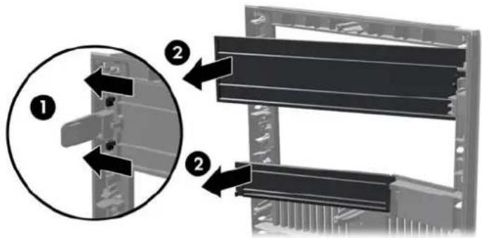
To remove a bezel blank, push the two retaining tabs that hold the bezel blank in place towards the outer right edge of the bezel (1) and slide the bezel blank back and to the right to remove it (2).
Figure 2-5 Removing a Bezel Blank
Replacing the Front Bezel
Insert the three hooks on the left side of the bezel into the rectangular holes on the chassis (1) then rotate the right side of the bezel onto the chassis (2) and snap it into place.
Figure 2-6 Replacing the Front Bezel

System Board Connections
Refer to the following illustrations and tables to identify the system board connectors for your model.
Figure 2-7 System Board Connections

Table 2-1 System Board Connections
| No. System Board Connector System Board Label Color Component | ||
| 1 DIMM4 (Channel A) DIMM4 white Memory Module | ||
| 2 DIMM3 (Channel A) DIMM3 black Memory Module | ||
| 3 DIMM2 (Channel B) DIMM2 white Memory Module | ||
| 4 DIMM1 (Channel B) DIMM1 black Memory Module | ||
| 5 Power SATAPWR1 black SATA Optical Drives | ||
| 6 Power SATAPWR0 black SATA Hard Drives | ||
| 7 SATA 3.0 SATA0 dark blue 1st Hard Drive | ||
| 8 SATA 2.0 SATA1 white 2nd Hard Drive, or 2nd Optical Drive | if an eSATA Adapter Cable exists | |
| 9 SATA 2.0 SATA2 white 1st Optical Drive | ||
| 10 eSATA | ESATA | black eSATA Adapter Cable, or 2nd Optical Drive |
| 11 Parallel Port | PAR | black Parallel Port |
| 12 Serial Port | COMB | black Serial Port |
| 13 USB | MEDIA black USB Device, such as a Media Card Reader | |
| 14 Hood Lock | HLCK | black Hood Lock |
| 16 Hood Sensor | HSENSE | white Hood Sensor |
| 15 USB | MEDIA2 | black USB Device, such as a Media Card Reader |
| 17 PCI Express x1 | X1PCIEXP1 | black Expansion Card |
Table 2-1 System Board Connections (continued)
| No. System Board Connector System Board Label Color Component |
| 18 PCI Express x1 X1PCIEXP2 black Expansion Card |
| 19 PCI Express x16 X16PCIEXP black Expansion Card |
| 20 PCI PCI1 white Expansion Card |
Installing Additional Memory
The computer comes with double data rate 3 synchronous dynamic random access memory (DDR3-SDRAM) dual inline memory modules (DIMMs).
DIMMs
The memory sockets on the system board can be populated with up to four industry-standard DIMMs. These memory sockets are populated with at least one preinstalled DIMM. To achieve the maximum memory support, you can populate the system board with up to 16-GB of memory configured in a high-performing dual channel mode.
DDR3-SDRAM DIMMs
CAUTION: This product DOES NOT support DDR3 Ultra Low Voltage (DDR3U) memory. The processor is not compatible with DDR3U memory and if you plug DDR3U memory into the system board, it can cause the physical damage to the DIMM or invoke system malfunction.
For proper system operation, the DDR3-SDRAM DIMMs must be:
• industry-standard 240-pin
• unbuffered non-ECC PC3-12800 DDR3-1600 MHz-compliant
1.5 volt DDR3-SDRAM DIMMs
The DDR3-SDRAM DIMMs must also:
• support CAS latency 11 DDR3 1600 MHz (11-11-11 timing)
• contain the mandatory JEDEC SPD information
In addition, the computer supports:
512-Mbit, 1-Gbit, and 2-Gbit non-ECC memory technologies
• single-sided and double-sided DIMMs
- DIMMs constructed with x8 and x16 DDR devices; DIMMs constructed with x4 SDRAM are not supported
NOTE: The system will not operate properly if you install unsupported DIMMs.
Populating DIMM Sockets
There are four DIMM sockets on the system board, with two sockets per channel. The sockets are labeled DIMM1, DIMM2, DIMM3, and DIMM4. Sockets DIMM1 and DIMM2 operate in memory channel B. Sockets DIMM3 and DIMM4 operate in memory channel A.
The system will automatically operate in single channel mode, dual channel mode, or flex mode, depending on how the DIMMs are installed.
- The system will operate in single channel mode if the DIMM sockets are populated in one channel only.
- The system will operate in a higher-performing dual channel mode if the total memory capacity of the DIMMs in Channel A is equal to the total memory capacity of the DIMMs in Channel B. The technology and device width can vary between the channels. For example, if Channel A is populated with two 1-GB DIMMs and Channel B is populated with one 2-GB DIMM, the system will operate in dual channel mode.
- The system will operate in flex mode if the total memory capacity of the DIMMs in Channel A is not equal to the total memory capacity of the DIMMs in Channel B. In flex mode, the channel populated with the least amount of memory describes the total amount of memory assigned to dual channel and the remainder is assigned to single channel. For optimal speed, the channels should be balanced so that the largest amount of memory is spread between the two channels. If one channel will have more memory than the other, the larger amount should be assigned to Channel A. For example, if you are populating the sockets with one 2-GB DIMM, and three 1-GB DIMMs, Channel A should be populated with the 2-GB DIMM and one 1-GB DIMM, and Channel B should be populated with the other two 1-GB DIMMs. With this configuration, 4-GB will run as dual channel and 1-GB will run as single channel.
In any mode, the maximum operational speed is determined by the slowest DIMM in the system.
Installing DIMMs
CAUTION: You must disconnect the power cord and wait approximately 30 seconds for the power to drain before adding or removing memory modules. Regardless of the power-on state, voltage is always supplied to the memory modules as long as the computer is plugged into an active AC outlet. Adding or removing memory modules while voltage is present may cause irreparable damage to the memory modules or system board.
The memory module sockets have gold-plated metal contacts. When upgrading the memory, it is important to use memory modules with gold-plated metal contacts to prevent corrosion and/or oxidation resulting from having incompatible metals in contact with each other.
Static electricity can damage the electronic components of the computer or optional cards. Before beginning these procedures, ensure that you are discharged of static electricity by briefly touching a grounded metal object. For more information, refer to Electrostatic Discharge on page 92.
When handling a memory module, be careful not to touch any of the contacts. Doing so may damage the module.
- Remove/disengage any security devices that prohibit opening the computer.
- Remove all removable media, such as compact discs or USB flash drives, from the computer.
- Turn off the computer properly through the operating system, then turn off any external devices.
- Disconnect the power cord from the power outlet and disconnect any external devices.
CAUTION: You must disconnect the power cord and wait approximately 30 seconds for the power to drain before adding or removing memory modules. Regardless of the power-on state, voltage is always supplied to the memory modules as long as the computer is plugged into an active AC outlet. Adding or removing memory modules while voltage is present may cause irreparable damage to the memory modules or system board.
- Remove the computer access panel.

WARNING! To reduce risk of personal injury from hot surfaces, allow the internal system components to cool before touching.
- Open both latches of the memory module socket (1), and insert the memory module into the socket (2).
Figure 2-8 Installing a DIMM
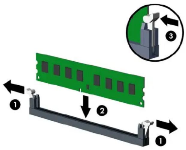

NOTE: A memory module can be installed in only one way. Match the notch on the module with the tab on the memory socket.
Populate the black DIMM sockets before the white DIMM sockets.
For maximum performance, populate the sockets so that the memory capacity is spread as equally as possible between Channel A and Channel B. Refer to Populating DIMM Sockets on page 17 for more information.
- Push the module down into the socket, ensuring that the module is fully inserted and properly seated. Make sure the latches are in the closed position (3).
- Repeat steps 6 and 7 to install any additional modules.
- Replace the computer access panel.
- Reconnect the power cord and turn on the computer.
- Lock any security devices that were disengaged when the access panel was removed.
The computer should automatically recognize the additional memory the next time you turn on the computer.
Removing or Installing an Expansion Card
The computer has one PCI expansion slot, two PCI Express x1 expansion slots, and one PCI Express x16 expansion slot.

NOTE: You can install a PCI Express x1, x4, x8, or x16 expansion card in the PCI Express x16 slot.
To remove, replace, or add an expansion card:
- Remove/disengage any security devices that prohibit opening the computer.
- Remove all removable media, such as compact discs or USB flash drives, from the computer.
- Turn off the computer properly through the operating system, then turn off any external devices.
- Disconnect the power cord from the power outlet and disconnect any external devices.

CAUTION: Regardless of the power-on state, voltage is always present on the system board as long as the system is plugged into an active AC outlet. You must disconnect the power cord to avoid damage to the internal components of the computer.
- Remove the computer access panel.
- Locate the correct vacant expansion socket on the system board and the corresponding expansion slot on the back of the computer chassis.
- Release the slot cover retention latch that secures the PCI slot covers by lifting the green tab on the latch and rotating the latch to the open position.
Figure 2-9 Opening the Expansion Slot Retainer

- Before installing an expansion card, remove the expansion slot cover or the existing expansion card.

NOTE: Before removing an installed expansion card, disconnect any cables that may be attached to the expansion card.
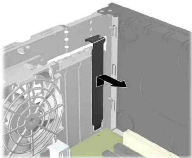
a. If you are installing an expansion card in a vacant socket, remove the appropriate expansion slot cover on the back of the chassis. Pull the slot cover straight up then away from the inside of the chassis.
Figure 2-10 Removing an Expansion Slot Cover
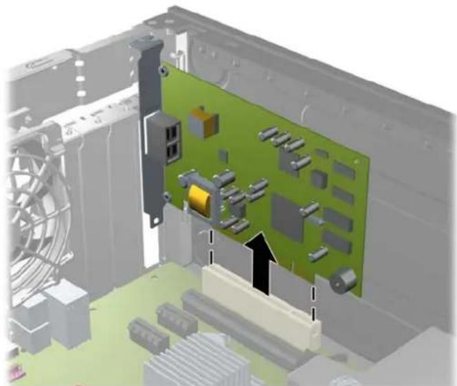
b. If you are removing a standard PCI card or PCI Express x1 card, hold the card at each end, and carefully rock it back and forth until the connectors pull free from the socket. Pull the expansion card straight up from the socket then away from the inside of the chassis to release it from the chassis frame. Be sure not to scrape the card against the other components.
Figure 2-11 Removing a Standard PCI Expansion Card
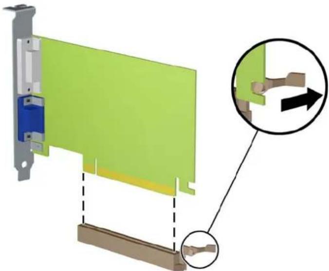
c. If you are removing a PCI Express x16 card, pull the retention arm on the back of the expansion socket away from the card and carefully rock the card back and forth until the connectors pull free from the socket. Pull the expansion card straight up from the socket then away from the inside of the chassis to release it from the chassis frame. Be sure not to scrape the card against the other components.
Figure 2-12 Removing a PCI Express x16 Expansion Card
-
Store the removed card in anti-static packaging.
-
If you are not installing a new expansion card, install an expansion slot cover to close the open slot.
CAUTION: After removing an expansion card, you must replace it with a new card or expansion slot cover for proper cooling of internal components during operation.
- To install a new expansion card, hold the card just above the expansion socket on the system board then move the card toward the rear of the chassis so that the bracket on the card is aligned with the open slot on the rear of the chassis. Press the card straight down into the expansion socket on the system board.
Figure 2-13 Installing an Expansion Card
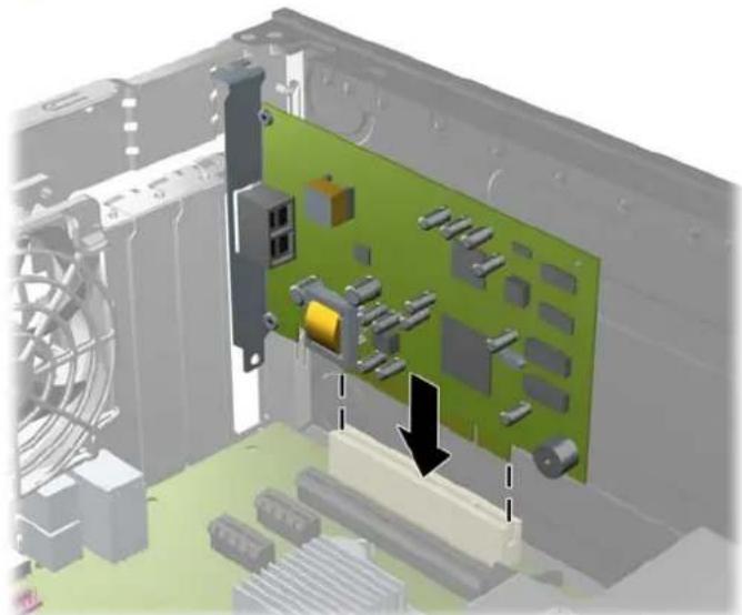
NOTE: When installing an expansion card, press firmly on the card so that the whole connector seats properly in the expansion card slot.
- Rotate the slot cover retention latch back in place to secure the expansion card.
Figure 2-14 Closing the Expansion Slot Retainer

-
Connect external cables to the installed card, if needed. Connect internal cables to the system board, if needed.
-
Replace the computer access panel.
- Reconnect the power cord and turn on the computer.
- Lock any security devices that were disengaged when the access panel was removed.
- Reconfigure the computer, if necessary.
Drive Positions
Figure 2-15 Drive Positions

Table 2-2 Drive Positions
| 1 Two 5.25-inch drive bays for optional drives (optical drives shown) |
| 2 One 3.5-inch drive bay for optional drive (media card reader shown) |
| 3 Secondary 3.5-inch internal hard drive bay for optional hard drive |
| 4 Primary 3.5-inch internal hard drive bay |
| NOTE: The drive configuration on your computer may be different than the drive configuration shown above. |
To verify the type and size of the storage devices installed in the computer, run Computer Setup.
Installing and Removing Drives
When installing drives, follow these guidelines:
- The primary Serial ATA (SATA) hard drive must be connected to the dark blue primary SATA connector on the system board labeled SATA0. If you are adding a second hard drive, connect it to the white connector on the system board labeled SATA1.
- Connect the first SATA optical drive to the white SATA connector on the system board labeled SATA2. If you are adding a second optical drive connect it to the black SATA connector on the system board labeled ESATA. If the ESATA connector is already populated, connect the second optical drive to the white connector labeled SATA1.
- Connect an optional eSATA adapter cable to the black SATA connector on the system board labeled ESATA.
- Connect a media card reader USB cable to the USB connector on the system board labeled MEDIA
- The power cable for the SATA optical drives is a two-headed cable this is plugged into the system board with the first connector routed to the top 5.25-inch bay and the second connector routed to the bottom 5.25-inch bay.
- The power cable for the SATA hard drives is a two-headed cable this is plugged into the system board with the first connector routed to the bottom 3.5-inch bay and the second connector routed to the top 3.5-inch bay.
• The system does not support Parallel ATA (PATA) optical drives or PATA hard drives. - You must install guide screws to ensure the drive will line up correctly in the drive cage and lock in place. HP has provided extra guide screws for the drive bays (four 6-32 isolation mounting guide screws and eight M3 metric guide screws), installed on the side of the drive bays. The 6-32 isolation mounting screws are required for a secondary hard drive. All other drives (except the primary hard drive) use M3 metric screws. The HP-supplied metric screws are black and the HP-supplied isolation mounting screws are silver and blue. If you are replacing the primary hard drive, you must remove the four silver and blue 6-32 isolation mounting guide screws from the old hard drive and install them in the new hard drive.
Figure 2-16 Extra Guide Screw Locations
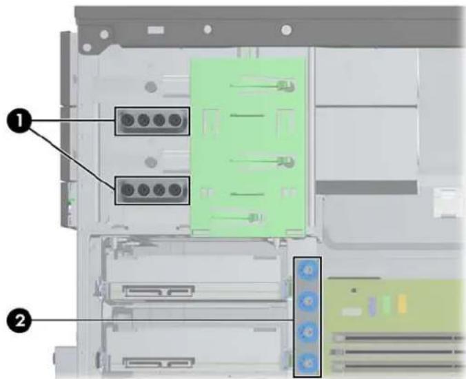
No. Guide Screw Device
1 Black M3 Metric Screws All Drives (except hard drives)
2 Silver and Blue 6-32 Isolation Mounting Screws Secondary Hard Drive
CAUTION: To prevent loss of work and damage to the computer or drive:
If you are inserting or removing a drive, shut down the operating system properly, turn off the computer, and unplug the power cord. Do not remove a drive while the computer is on or in standby mode.
Before handling a drive, ensure that you are discharged of static electricity. While handling a drive, avoid touching the connector. For more information about preventing electrostatic damage, refer to Electrostatic Discharge on page 92.
Handle a drive carefully; do not drop it.
Do not use excessive force when inserting a drive.
Avoid exposing a hard drive to liquids, temperature extremes, or products that have magnetic fields such as monitors or speakers.
If a drive must be mailed, place the drive in a bubble-pack mailer or other protective packaging and label the package “Fragile: Handle With Care.”
Removing a 5.25-inch or 3.5-inch Drive from a Drive Bay

CAUTION: All removable media should be taken out of a drive before removing the drive from the computer.
- Remove/disengage any security devices that prohibit opening the computer.
- Remove all removable media, such as compact discs or USB flash drives, from the computer.
- Turn off the computer properly through the operating system, then turn off any external devices.
- Disconnect the power cord from the power outlet and disconnect any external devices.

CAUTION: Regardless of the power-on state, voltage is always present on the system board as long as the system is plugged into an active AC outlet. You must disconnect the power cord to avoid damage to the internal components of the computer.
-
Remove the access panel and front bezel.
-
Disconnect the drive cables, as indicated in the following illustrations.

CAUTION: When removing the cables, pull the tab or connector instead of the cable itself to avoid damaging the cable.
a. If you are removing an optical drive, disconnect the power cable (1) and data cable (2) from the back of the drive.
Figure 2-17 Disconnecting the Optical Drive Cables

b. If you are removing a media card reader, disconnect the USB cable from the system board.
Figure 2-18 Disconnecting the Media Card Reader USB Cable

- A latch drive bracket with release tabs secures the drives in the drive bay. Lift the release tab on the latch drive bracket (1) for the drive you want to remove, then slide the drive from its drive bay (2).
Figure 2-19 Removing the Drives

Installing a 5.25-inch or 3.5-inch Drive into a Drive Bay
- Remove/disengage any security devices that prohibit opening the computer.
- Remove all removable media, such as compact discs or USB flash drives, from the computer.
- Turn off the computer properly through the operating system, then turn off any external devices.
- Disconnect the power cord from the power outlet and disconnect any external devices.
CAUTION: Regardless of the power-on state, voltage is always present on the system board as long as the system is plugged into an active AC outlet. You must disconnect the power cord to avoid damage to the internal components of the computer.
-
Remove the computer access panel.
-
Remove the front bezel. If you are installing a drive in a bay covered by a bezel blank, remove the bezel blank. See Removing Bezel Blanks on page 14 for more information.
-
Install four M3 metric guide screws in the lower holes on each side of the drive. HP has provided eight extra M3 metric guide screws on the front of the chassis, under the front bezel. The M3 metric guide screws are black. Refer to Installing and Removing Drives on page 25 for an illustration of the extra M3 metric guide screws location.
NOTE: When replacing the drive, transfer the four M3 metric guide screws from the old drive to the new one.
CAUTION: Use only 5-mm long screws as guide screws. Longer screws can damage the internal components of the drive.
Figure 2-20 Installing Guide Screws (Optical Drive Shown)

- Slide the drive into the drive bay, making sure to align the guide screws with the guide slots, until the drive snaps into place.
Figure 2-21 Sliding the Drives into the Drive Cage
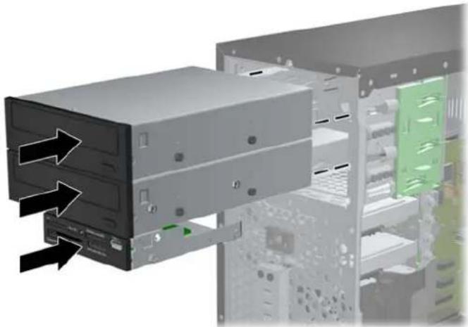
- Connect the power and data cables to the drive as indicated in the following illustrations.
a. If you are installing an optical drive, connect the power cable (1) and data cable (2) to the back of the drive.

NOTE: The power cable for the optical drives is a two-headed cable that is routed from the system board to the rear of the optical drive bays.
Figure 2-22 Connecting the Optical Drive Cables

b. If your are installing a media card reader, connect the USB cable to the USB system board connector labeled MEDIA.
Figure 2-23 Connecting the Media Card Reader USB Cable

- If installing a new drive, connect the opposite end of the data cable to the appropriate system board connector.

NOTE: If you are installing a new SATA optical drive, connect the data cable for the first optical drive to the white SATA connector on the system board labeled SATA2. Connect the data cable for a second optical drive to the black SATA connector on the system board labeled ESATA. If the ESATA connector is already populated, connect the second optical drive to white connector labeled SATA1.
Refer to System Board Connections on page 16 for an illustration of the system board drive connectors.
- Replace the front bezel and computer access panel.
- Reconnect the power cord and any external devices, then turn on the computer.
- Lock any security devices that were disengaged when the access panel was removed.
Removing a Hard Drive from a Drive Bay

NOTE: Before you remove the old hard drive, be sure to back up the data from the old hard drive so that you can transfer the data to the new hard drive.
- Remove/disengage any security devices that prohibit opening the computer.
- Remove all removable media, such as compact discs or USB flash drives, from the computer.
- Turn off the computer properly through the operating system, then turn off any external devices.
- Disconnect the power cord from the power outlet and disconnect any external devices.

CAUTION: Regardless of the power-on state, voltage is always present on the system board as long as the system is plugged into an active AC outlet. You must disconnect the power cord to avoid damage to the internal components of the computer.
-
Remove the computer access panel.
-
Disconnect the power cable (1) and data cable (2) from the back of the hard drive.
Figure 2-24 Disconnecting the Hard Drive Cables

- Release the drive by pulling the release tab away from the drive (1) and sliding the drive out of the bay (2).
Figure 2-25 Removing a Hard Drive

- Remove the four guide screws (two on each side) from the old drive. You will need these screws to install a new drive.
Installing a Hard Drive into an Internal Drive Bay

NOTE: The system does not support Parallel ATA (PATA) hard drives.
- Remove/disengage any security devices that prohibit opening the computer.
- Remove all removable media, such as compact discs or USB flash drives, from the computer.
- Turn off the computer properly through the operating system, then turn off any external devices.
- Disconnect the power cord from the power outlet and disconnect any external devices.

CAUTION: Regardless of the power-on state, voltage is always present on the system board as long as the system is plugged into an active AC outlet. You must disconnect the power cord to avoid damage to the internal components of the computer.
-
Remove the access panel.
-
Install guide screws on the sides of the drive. If you are installing a 2.5-inch drive, you must install the drive in an adapter bracket.

NOTE: The hard drive uses 6-32 isolation mounting guide screws. Four extra guide screws are installed on the exterior of the hard drive bays. The HP-supplied isolation mounting guide screws are silver and blue. Refer to Installing and Removing Drives on page 25 for an illustration of the extra 6-32 isolation mounting guide screws location.
If you are replacing a drive, transfer the guides screws from the old drive to the new one.
- If you are installing a 3.5-inch hard drive, install four isolation mounting guide screws (two on each side of the drive).
Figure 2-26 Installing Isolation Mounting Guide Screws in a 3.5-inch Drive

• If you are installing a 2.5-inch hard drive:
Slide the drive into the bay adapter bracket, ensuring the connector on the drive is fully inserted into the connector on the adapter bracket.
Figure 2-27 Sliding the 2.5-inch Drive in the Adapter Bracket
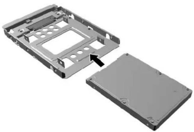
Secure the drive to the bay adapter bracket by installing four black M3 adapter bracket screws through the sides of the bracket into the drive.
Figure 2-28 Securing the Drive in the Adapter Bracket

• Install four 6-32 silver and blue isolation mounting guide screws in the adapter bracket (two on each side of the bracket).
Figure 2-29 Installing Isolation Mounting Guide Screws in the Adapter Bracket

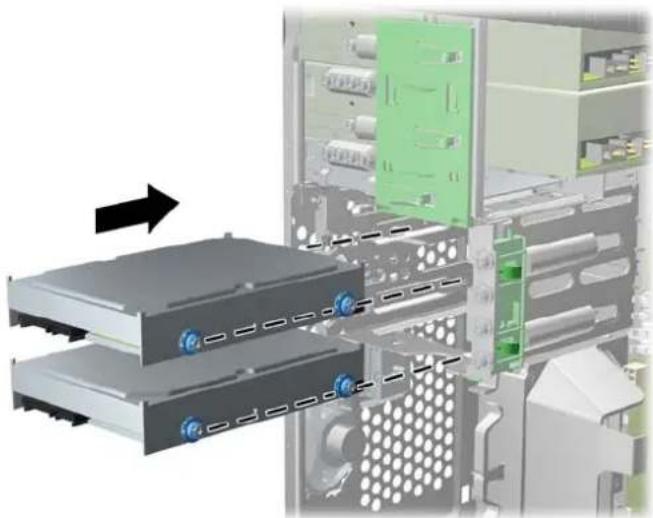
- Slide the drive into the drive bay, making sure to align the guide screws with the guide slots, until the drive snaps into place. The bottom bay is for the primary hard drive. The upper bay is for an optional secondary hard drive.
Figure 2-30 Sliding a Hard Drive into the Drive Bay
- Connect the power cable (1) and data cable (2) to the back of the hard drive.

NOTE: The power cable for the hard drives is a two-headed cable that is routed from the system board to the rear of the hard drive bays.
Figure 2-31 Connecting the Hard Drive Cables

- If installing a new drive, connect the opposite end of the data cable to the appropriate system board connector.

NOTE: If your system has only one SATA hard drive, you must connect the hard drive data cable to the dark blue connector labeled SATA0 to avoid any hard drive performance problems. If you are adding a second hard drive, connect the data cable to the white connector labeled SATA1.
-
Route the power and data cables in their cable retainers.
-
Replace the computer access panel.
-
Reconnect the power cord and any external devices, then turn on the computer.
- Lock any security devices that were disengaged when the access panel was removed.
Installing a Security Lock
The security locks displayed below and on the following pages can be used to secure the computer.
Cable Lock
Figure 2-32 Installing a Cable Lock

Padlock
Figure 2-33 Installing a Padlock

HP Business PC Security Lock
- Fasten the security cable by looping it around a stationary object.
Figure 2-34 Securing the Cable to a Fixed Object

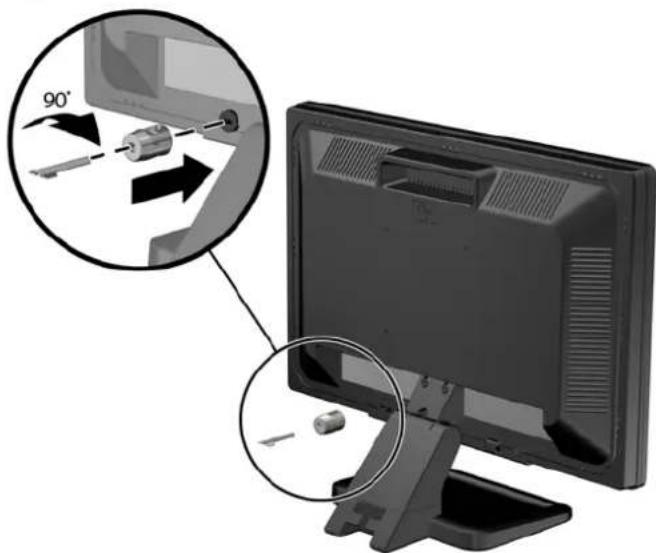
- Insert the Cable lock into the Cable lock slot on the back of the monitor and secure the lock to the monitor by inserting the key into the key hole on the rear of the lock and rotating the key 90 degrees.
Figure 2-35 Installing the Cable Lock on the Monitor
- Slide the security cable through the hole in the Cable lock on the rear of the monitor.
Figure 2-36 Securing the Monitor

- Use the bracket provided in the kit to secure other peripheral devices by laying the device cable across the center of the bracket (1) and inserting the security cable through one of the two holes in the bracket (2). Use the hole in the bracket that best secures the peripheral device cable.
Figure 2-37 Securing Peripheral Devices (Printer Shown)

- Thread the keyboard and mouse cables through the computer chassis lock.
Figure 2-38 Threading the Keyboard and Mouse Cables

- Screw the lock to the chassis in the thumbscrew hole using the screw provided.
Figure 2-39 Attaching the Lock to the Chassis

- Insert the plug end of the security cable into the lock (1) and push the button in (2) to engage the lock. Use the key provided to disengage the lock.
Figure 2-40 Engaging the Lock

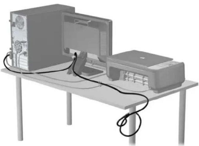
- When complete, all devices in your workstation will be secured.
Figure 2-41 Secured Workstation
Front Bezel Security
The front bezel can be locked in place by installing a security screw provided by HP. To install the security screw:
- Remove/disengage any security devices that prohibit opening the computer.
- Remove all removable media, such as compact discs or USB flash drives, from the computer.
- Turn off the computer properly through the operating system, then turn off any external devices.
- Disconnect the power cord from the power outlet and disconnect any external devices.
CAUTION: Regardless of the power-on state, voltage is always present on the system board as long as the system is plugged into an active AC outlet. You must disconnect the power cord to avoid damage to the internal components of the computer.
-
Remove the access panel and front bezel.
-
Remove the security screw from the inside of the front bezel.
Figure 2-42 Retrieving the Front Bezel Security Screw

-
Replace the front bezel.
-
Install the screw through the interior of the front of the chassis into the front bezel. The screw hole is located toward the middle of the right edge of the chassis between the hard drive bay and speaker.
Figure 2-43 Installing the Front Bezel Security Screw

- Replace the access panel.
- Reconnect the power cord and turn on the computer.
- Lock any security devices that were disengaged when the access panel was removed.
3 Small Form Factor (SFF) Hardware Upgrades
Serviceability Features
The computer includes features that make it easy to upgrade and service. No tools are needed for most of the installation procedures described in this chapter.
Warnings and Cautions
Before performing upgrades be sure to carefully read all of the applicable instructions, cautions, and warnings in this guide.
WARNING! To reduce the risk of personal injury from electrical shock, hot surfaces, or fire:
Disconnect the power cord from the wall outlet and allow the internal system components to cool before touching.
Do not plug telecommunications or telephone connectors into the network interface controller (NIC) receptacles.
Do not disable the power cord grounding plug. The grounding plug is an important safety feature.
Plug the power cord in a grounded (earthed) outlet that is easily accessible at all times.
To reduce the risk of serious injury, read the Safety & Comfort Guide. It describes proper workstation, setup, posture, and health and work habits for computer users, and provides important electrical and mechanical safety information. This guide is located on the Web at http://www.hp.com/ergo.
WARNING! Energized and moving parts inside.
Disconnect power to the equipment before removing the enclosure.
Replace and secure the enclosure before re-energizing the equipment.
CAUTION: Static electricity can damage the electrical components of the computer or optional equipment. Before beginning these procedures, ensure that you are discharged of static electricity by briefly touching a grounded metal object. See Electrostatic Discharge on page 92 for more information.
When the computer is plugged into an AC power source, voltage is always applied to the system board. You must disconnect the power cord from the power source before opening the computer to prevent damage to internal components.
Removing the Computer Access Panel
To access internal components, you must remove the access panel:
- Remove/disengage any security devices that prohibit opening the computer.
- Remove all removable media, such as compact discs or USB flash drives, from the computer.
- Turn off the computer properly through the operating system, then turn off any external devices.
- Disconnect the power cord from the power outlet and disconnect any external devices.
CAUTION: Regardless of the power-on state, voltage is always present on the system board as long as the system is plugged into an active AC outlet. You must disconnect the power cord to avoid damage to the internal components of the computer.
-
If the computer is on a stand, remove the computer from the stand and lay the computer down.
-
Lift up on the access panel handle (1) then lift the access panel off the computer (2).
Figure 3-1 Removing the Computer Access Panel

Replacing the Computer Access Panel
Slide the lip on the front end of the access panel under the lip on the front of the chassis (1) then press the back end of the access panel onto the unit so that it locks into place (2).
Figure 3-2 Replacing the Computer Access Panel

Removing the Front Bezel
- Remove/disengage any security devices that prohibit opening the computer.
- Remove all removable media, such as compact discs or USB flash drives, from the computer.
- Turn off the computer properly through the operating system, then turn off any external devices.
- Disconnect the power cord from the power outlet and disconnect any external devices.
CAUTION: Regardless of the power-on state, voltage is always present on the system board as long as the system is plugged into an active AC outlet. You must disconnect the power cord to avoid damage to the internal components of the computer.
-
If the computer is on a stand, remove the computer from the stand and lay the computer down.
-
Remove the computer access panel.
-
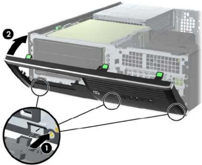
Lift up the three tabs on the side of the bezel (1), then rotate the bezel off the chassis (2).
Figure 3-3 Removing the Front Bezel

Removing Bezel Blanks
On some models, there are bezel blanks covering the 3.5-inch and 5.25-inch drive bays that need to be removed before installing a drive. To remove a bezel blank:
-
Remove the access panel and front bezel.
-
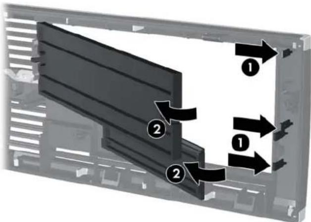
To remove a bezel blank, push the two retaining tabs that hold the bezel blank in place towards the outer right edge of the bezel (1) and slide the bezel blank back and to the right to remove it (2).
Figure 3-4 Removing a Bezel Blank
Replacing the Front Bezel
Insert the three hooks on the bottom side of the bezel into the rectangular holes on the chassis (1) then rotate the top side of the bezel onto the chassis (2) and snap it into place.
Figure 3-5 Replacing the Front Bezel
Changing from Desktop to Tower Configuration
The Small Form Factor computer can be used in a tower orientation with an optional tower stand that can be purchased from HP.
- Remove/disengage any security devices that prohibit opening the computer.
- Remove all removable media, such as compact discs or USB flash drives, from the computer.
- Turn off the computer properly through the operating system, then turn off any external devices.
- Disconnect the power cord from the power outlet and disconnect any external devices.

CAUTION: Regardless of the power-on state, voltage is always present on the system board as long as the system is plugged into an active AC outlet. You must disconnect the power cord to avoid damage to the internal components of the computer.
- Orient the computer so that its right side is facing down and place the computer in the optional stand.
Figure 3-6 Changing from Desktop to Tower Orientation


NOTE: To stabilize the computer in a tower orientation, HP recommends the use of the optional tower stand.
- Reconnect the power cord and any external devices, then turn on the computer.

NOTE: Ensure at least 10.2 centimeters (4 inches) of space on all sides of the computer remains clear and free of obstructions.
- Lock any security devices that were disengaged when the access panel was removed.
System Board Connections
Refer to the following illustration and table to identify the system board connectors for your model.
Figure 3-7 System Board Connections

Table 3-1 System Board Connections
| No. System Board Connector System Board Label Color Component | ||
| 1 DIMM4 (Channel A) DIMM4 white Memory Module | ||
| 2 DIMM3 (Channel A) DIMM3 black Memory Module | ||
| 3 DIMM2 (Channel B) DIMM2 white Memory Module | ||
| 4 DIMM1 (Channel B) DIMM1 black Memory Module | ||
| 5 Power SATAPWR1 black (unused) | ||
| 6 Power SATAPWR1 black SATA Optical and Hard Drives | ||
| 7 SATA 3.0 SATA0 dark blue 1st Hard Drive | ||
| 8 SATA 2.0 SATA1 white 2nd Hard Drive, or 2nd Optical Drive if an eSATA Adapter Cable exists | ||
| 9 SATA 2.0 SATA2 white 1st Optical Drive | ||
| 10 eSATA | ESATA | black eSATA Adapter Cable, or 2nd Optical Drive |
| 11 Parallel Port | PAR | black Parallel Port |
| 12 Serial Port | COMB | black Serial Port |
| 13 USB | MEDIA black USB Device, such as a Media Card Reader | |
| 14 Hood Lock | HLCK | black Hood Lock |
| 15 USB | MEDIA2 | black USB Device, such as a Media Card Reader |
| 16 Hood Sensor | HSENSE | white Hood Sensor |
| 17 PCI Express x1 | X1PCIEXP1 | black Expansion Card |
Table 3-1 System Board Connections (continued)
| No. System Board Connector System Board Label Color Component |
| 18 PCI Express x1 X4PCIEXP black Expansion Card |
| 19 PCI Express x16 X16PCIEXP black Expansion Card |
| 20 PCI PCI white Expansion Card |
Installing Additional Memory
The computer comes with double data rate 3 synchronous dynamic random access memory (DDR3-SDRAM) dual inline memory modules (DIMMs).
DIMMs
The memory sockets on the system board can be populated with up to four industry-standard DIMMs. These memory sockets are populated with at least one preinstalled DIMM. To achieve the maximum memory support, you can populate the system board with up to 16-GB of memory configured in a high-performing dual channel mode.
DDR3-SDRAM DIMMs
CAUTION: This product DOES NOT support DDR3 Ultra Low Voltage (DDR3U) memory. The processor is not compatible with DDR3U memory and if you plug DDR3U memory into the system board, it can cause the physical damage to the DIMM or invoke system malfunction.
For proper system operation, the DDR3-SDRAM DIMMs must be:
• industry-standard 240-pin
• unbuffered non-ECC PC3-12800 DDR3-1600 MHz-compliant
1.5 volt DDR3-SDRAM DIMMs
The DDR3-SDRAM DIMMs must also:
• support CAS latency 11 DDR3 1600 MHz (11-11-11 timing)
• contain the mandatory JEDEC SPD information
In addition, the computer supports:
512-Mbit, 1-Gbit, and 2-Gbit non-ECC memory technologies
• single-sided and double-sided DIMMs
- DIMMs constructed with x8 and x16 DDR devices; DIMMs constructed with x4 SDRAM are not supported
NOTE: The system will not operate properly if you install unsupported DIMMs.
Populating DIMM Sockets
There are four DIMM sockets on the system board, with two sockets per channel. The sockets are labeled DIMM1, DIMM2, DIMM3, and DIMM4. Sockets DIMM1 and DIMM2 operate in memory channel B. Sockets DIMM3 and DIMM4 operate in memory channel A.
The system will automatically operate in single channel mode, dual channel mode, or flex mode, depending on how the DIMMs are installed.
- The system will operate in single channel mode if the DIMM sockets are populated in one channel only.
- The system will operate in a higher-performing dual channel mode if the total memory capacity of the DIMMs in Channel A is equal to the total memory capacity of the DIMMs in Channel B. The technology and device width can vary between the channels. For example, if Channel A is populated with two 1-GB DIMMs and Channel B is populated with one 2-GB DIMM, the system will operate in dual channel mode.
- The system will operate in flex mode if the total memory capacity of the DIMMs in Channel A is not equal to the total memory capacity of the DIMMs in Channel B. In flex mode, the channel populated with the least amount of memory describes the total amount of memory assigned to dual channel and the remainder is assigned to single channel. For optimal speed, the channels should be balanced so that the largest amount of memory is spread between the two channels. If one channel will have more memory than the other, the larger amount should be assigned to Channel A. For example, if you are populating the sockets with one 2-GB DIMM, and three 1-GB DIMMs, Channel A should be populated with the 2-GB DIMM and one 1-GB DIMM, and Channel B should be populated with the other two 1-GB DIMMs. With this configuration, 4-GB will run as dual channel and 1-GB will run as single channel.
In any mode, the maximum operational speed is determined by the slowest DIMM in the system.
Installing DIMMs
CAUTION: You must disconnect the power cord and wait approximately 30 seconds for the power to drain before adding or removing memory modules. Regardless of the power-on state, voltage is always supplied to the memory modules as long as the computer is plugged into an active AC outlet. Adding or removing memory modules while voltage is present may cause irreparable damage to the memory modules or system board.
The memory module sockets have gold-plated metal contacts. When upgrading the memory, it is important to use memory modules with gold-plated metal contacts to prevent corrosion and/or oxidation resulting from having incompatible metals in contact with each other.
Static electricity can damage the electronic components of the computer or optional cards. Before beginning these procedures, ensure that you are discharged of static electricity by briefly touching a grounded metal object. For more information, refer to Electrostatic Discharge on page 92.
When handling a memory module, be careful not to touch any of the contacts. Doing so may damage the module.
- Remove/disengage any security devices that prohibit opening the computer.
- Remove all removable media, such as compact discs or USB flash drives, from the computer.
- Turn off the computer properly through the operating system, then turn off any external devices.
- Disconnect the power cord from the power outlet and disconnect any external devices.
CAUTION: You must disconnect the power cord and wait approximately 30 seconds for the power to drain before adding or removing memory modules. Regardless of the power-on state, voltage is always supplied to the memory modules as long as the computer is plugged into an active AC outlet. Adding or removing memory modules while voltage is present may cause irreparable damage to the memory modules or system board.
-
If the computer is on a stand, remove the computer from the stand.
-
Remove the computer access panel.

WARNING! To reduce risk of personal injury from hot surfaces, allow the internal system components to cool before touching.
- Rotate up the internal drive bay housing to access the memory module sockets on the system board.
Figure 3-8 Rotating the Drive Cage Up

- Open both latches of the memory module socket (1), and insert the memory module into the socket (2).
Figure 3-9 Installing a DIMM


NOTE: A memory module can be installed in only one way. Match the notch on the module with the tab on the memory socket.
Populate the black DIMM sockets before the white DIMM sockets.
For maximum performance, populate the sockets so that the memory capacity is spread as equally as possible between Channel A and Channel B. Refer to Populating DIMM Sockets on page 51 for more information.
- Push the module down into the socket, ensuring that the module is fully inserted and properly seated. Make sure the latches are in the closed position (3).
- Repeat steps 8 and 9 to install any additional modules.
- Replace the access panel.
- If the computer was on a stand, replace the stand.
- Reconnect the power cord and turn on the computer.
- Lock any security devices that were disengaged when the access panel was removed.
The computer should automatically recognize the additional memory the next time you turn on the computer.
Removing or Installing an Expansion Card
The computer has one PCI expansion slot, two PCI Express x1 expansion slots, and one PCI Express x16 expansion slot.

NOTE: The PCI and PCI Express slots support only low profile cards.
You can install a PCI Express x1, x4, x8, or x16 expansion card in the PCI Express x16 slot.
To remove, replace, or add an expansion card:
- Remove/disengage any security devices that prohibit opening the computer.
- Remove all removable media, such as compact discs or USB flash drives, from the computer.
- Turn off the computer properly through the operating system, then turn off any external devices.
- Disconnect the power cord from the power outlet and disconnect any external devices.

CAUTION: Regardless of the power-on state, voltage is always present on the system board as long as the system is plugged into an active AC outlet. You must disconnect the power cord to avoid damage to the internal components of the computer.
-
If the computer is on a stand, remove the computer from the stand.
-
Remove the computer access panel.
-
Locate the correct vacant expansion socket on the system board and the corresponding expansion slot on the back of the computer chassis.
-
Release the slot cover retention latch that secures the PCI slot covers by lifting the green tab on the latch and rotating the latch to the open position.
Figure 3-10 Opening the Expansion Slot Retainer

- Before installing an expansion card, remove the expansion slot cover or the existing expansion card.

NOTE: Before removing an installed expansion card, disconnect any cables that may be attached to the expansion card.
a. If you are installing an expansion card in a vacant socket, remove the appropriate expansion slot cover on the back of the chassis. Pull the slot cover straight up then away from the inside of the chassis.

Figure 3-11 Removing an Expansion Slot Cover
b. If you are removing a standard PCI card or PCI Express x1 card, hold the card at each end, and carefully rock it back and forth until the connectors pull free from the socket. Pull the expansion card straight up from the socket (1) then away from the inside of the chassis to release it from the chassis frame (2). Be sure not to scrape the card against the other components.
Figure 3-12 Removing a Standard PCI Expansion Card

c. If you are removing a PCI Express x16 card, pull the retention arm on the back of the expansion socket away from the card and carefully rock the card back and forth until the connectors pull free from the socket. Pull the expansion card straight up from the socket then away from the inside of the chassis to release it from the chassis frame. Be sure not to scrape the card against the other components.
Figure 3-13 Removing a PCI Express x16 Expansion Card

-
Store the removed card in anti-static packaging.
-
If you are not installing a new expansion card, install an expansion slot cover to close the open slot.
CAUTION: After removing an expansion card, you must replace it with a new card or expansion slot cover for proper cooling of internal components during operation.
- To install a new expansion card, hold the card just above the expansion socket on the system board then move the card toward the rear of the chassis (1) so that the bracket on the card is aligned with the open slot on the rear of the chassis. Press the card straight down into the expansion socket on the system board (2).
Figure 3-14 Installing an Expansion Card
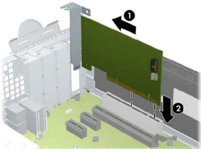

NOTE: When installing an expansion card, press firmly on the card so that the whole connector seats properly in the expansion card slot.
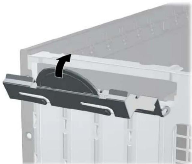
- Rotate the slot cover retention latch back in place to secure the expansion card.
Figure 3-15 Closing the Expansion Slot Retainer
- Connect external cables to the installed card, if needed. Connect internal cables to the system board, if needed.
- Replace the computer access panel.
- If the computer was on a stand, replace the stand.
-
Reconnect the power cord and turn on the computer.
-
Lock any security devices that were disengaged when the access panel was removed.
-
Reconfigure the computer, if necessary.
Drive Positions
Figure 3-16 Drive Positions
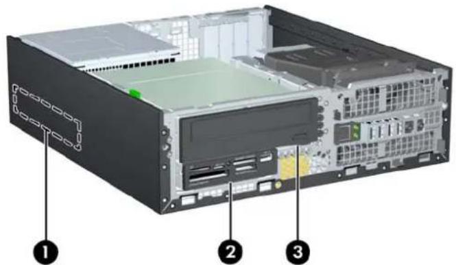
Table 3-2 Drive Positions
| 1 3.5-inch internal hard drive bay |
| 2 3.5-inch drive bay for optional drives (media card reader shown) |
| 3 5.25-inch drive bay for optional drives (optical drive shown) |
| NOTE: The drive configuration on your computer may be different than the drive configuration shown above. |
To verify the type and size of the storage devices installed in the computer, run Computer Setup.
Installing and Removing Drives
When installing drives, follow these guidelines:
- The primary Serial ATA (SATA) hard drive must be connected to the dark blue primary SATA connector on the system board labeled SATA0. If you are adding a second hard drive, connect it to the white connector on the system board labeled SATA1.
- Connect a SATA optical drive to the white SATA connector on the system board labeled SATA2.
- Connect an optional eSATA adapter cable to the black SATA connector on the system board labeled ESATA.
- Connect a media card reader USB cable to the USB connector on the system board labeled MEDIA.
- The power cable for the SATA drives is a three-headed cable that is plugged into the system board with the first connector routed to the rear of the hard drive, the second connector routed to the rear of the 3.5" drive, and the third connector routed to the rear of the 5.25" optical drive.
The system does not support Parallel ATA (PATA) optical drives or PATA hard drives. - You must install guide screws to ensure the drive will line up correctly in the drive cage and lock in place. HP has provided extra guide screws for the drive bays (five 6-32 standard screws and four M3 metric screws), installed in the front of the chassis, under the front bezel. The 6-32 standard screws are required for a secondary hard drive. All other drives (except the primary hard drive) use M3 metric screws. The HP-supplied metric screws are black and the HP-supplied standard screws are silver. If you are replacing the primary hard drive, you must remove the four silver and blue 6-32 isolation mounting guide screws from the old hard drive and install them in the new hard drive.
Figure 3-17 Extra Guide Screw Locations

No. Guide Screw Device
1 Black M3 Metric Screws All Drives (except primary and secondary hard drives)
2 Silver 6-32 Standard Screws Secondary Hard Drive
There are at total of five extra silver 6-32 standard screws. Four are used as guide screws for a secondary hard drive. The fifth is used for bezel security (see Front Bezel Security on page 80 for more information).

CAUTION: To prevent loss of work and damage to the computer or drive:
If you are inserting or removing a drive, shut down the operating system properly, turn off the computer, and unplug the power cord. Do not remove a drive while the computer is on or in standby mode.
Before handling a drive, ensure that you are discharged of static electricity. While handling a drive, avoid touching the connector. For more information about preventing electrostatic damage, refer to Electrostatic Discharge on page 92.
Handle a drive carefully; do not drop it.
Do not use excessive force when inserting a drive.
Avoid exposing a hard drive to liquids, temperature extremes, or products that have magnetic fields such as monitors or speakers.
If a drive must be mailed, place the drive in a bubble-pack mailer or other protective packaging and label the package "Fragile: Handle With Care."
Removing a 5.25-inch Drive from a Drive Bay

CAUTION: All removable media should be taken out of a drive before removing the drive from the computer.
- Remove/disengage any security devices that prohibit opening the computer.
- Remove all removable media, such as compact discs or USB flash drives, from the computer.
- Turn off the computer properly through the operating system, then turn off any external devices.
- Disconnect the power cord from the power outlet and disconnect any external devices.

CAUTION: Regardless of the power-on state, voltage is always present on the system board as long as the system is plugged into an active AC outlet. You must disconnect the power cord to avoid damage to the internal components of the computer.
-
If the computer is on a stand, remove the computer from the stand.
-
Remove the computer access panel.
-
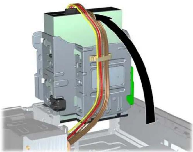
Rotate the drive cage to its upright position.
Figure 3-18 Rotating the Drive Cage Up
- If removing an optical drive, disconnect the power cable (1) and data cable (2) from the rear of the optical drive.
CAUTION: When removing the cables, pull the tab or connector instead of the cable itself to avoid damaging the cable.
Figure 3-19 Disconnecting the Power and Data Cables

- Rotate the drive cage back down to its normal position.
CAUTION: Be careful not to pinch any cables or wires when rotating the drive cage down.
Figure 3-20 Rotating the Drive Cage Down

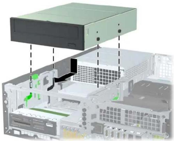
- Press down on the green drive retainer button located on the left side of the drive to disengage the drive from the drive cage (1). While pressing the drive retainer button, slide the drive back until it stops, then lift it up and out of the drive cage (2).
Figure 3-21 Removing the 5.25-inch Drive

Installing a 5.25-inch Drive into a Drive Bay
- Remove/disengage any security devices that prohibit opening the computer.
- Remove all removable media, such as compact discs or USB flash drives, from the computer.
- Turn off the computer properly through the operating system, then turn off any external devices.
- Disconnect the power cord from the power outlet and disconnect any external devices.
CAUTION: Regardless of the power-on state, voltage is always present on the system board as long as the system is plugged into an active AC outlet. You must disconnect the power cord to avoid damage to the internal components of the computer.
-
If the computer is on a stand, remove the computer from the stand.
-
Remove the computer access panel.
-
If you are installing a drive in a bay covered by a bezel blank, remove the front bezel then remove the bezel blank. See Removing Bezel Blanks on page 47 for more information.
-
Install four M3 metric guide screws in the lower holes on each side of the drive. HP has provided four extra M3 metric guide screws on the front of the chassis, under the front bezel. The M3 metric guide screws are black. Refer to Installing and Removing Drives on page 60 for an illustration of the extra M3 metric guide screws location.

NOTE: When replacing the drive, transfer the four M3 metric guide screws from the old drive to the new one.

CAUTION: Use only 5-mm long screws as guide screws. Longer screws can damage the internal components of the drive.
Figure 3-22 Installing Guide Screws in the Optical Drive

- Position the guide screws on the drive into the J-slots in the drive bay. Then slide the drive toward the front of the computer until it locks into place.
Figure 3-23 Installing the Optical Drive
- Rotate the drive cage to its upright position.
Figure 3-24 Rotating the Drive Cage Up

-
Connect the SATA data cable to the white SATA system board connector labeled SATA2.
-
Route the data cable through the cable guides.
CAUTION: There are two cable guides that keep the data cable from being pinched by the drive cage when raising or lowering it. One is located on the bottom side of the drive cage. The other is located on the chassis frame under the drive cage. Ensure that the data cable is routed through these guides before connecting it to the optical drive.
- Connect the power cable (1) and data cable (2) to the rear of the optical drive.
NOTE: The power cable for the optical drive is a three-headed cable that is routed from the system board to the hard drive, then to the rear of the optical drive.
Figure 3-25 Connecting the Power and Data Cables

- Rotate the drive cage back down to its normal position.

CAUTION: Be careful not to pinch any cables or wires when rotating the drive cage down.
Figure 3-26 Rotating the Drive Cage Down
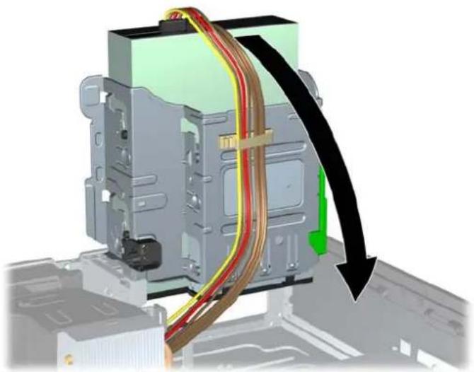
- Replace the front bezel (if removed) and access panel.
- If the computer was on a stand, replace the stand.
- Reconnect the power cord and turn on the computer.
- Lock any security devices that were disengaged when the access panel was removed.
Removing a 3.5-inch Drive from a Drive Bay

CAUTION: All removable media should be taken out of a drive before removing the drive from the computer.
The 3.5-inch drive is located underneath the 5.25-inch drive. You must remove the 5.25-inch drive before removing the 3.5-inch drive.
- Follow the procedure in Removing a 5.25-inch Drive from a Drive Bay on page 62 to remove the 5.25-inch drive and access the 3.5-inch drive.

CAUTION: Ensure that the computer is turned off and that the power cord is disconnected from the electrical outlet before proceeding.
- Disconnect the drive cables from the rear of the drive, or, if you are removing a media card reader, disconnect the USB cable from the system board as indicated in the following illustration.
Figure 3-27 Disconnecting the Media Card Reader USB Cable

- Press down on the green drive retainer button located on the left side of the drive to disengage the drive from the drive cage (1). While pressing the drive retainer button, slide the drive back until it stops, then lift it up and out of the drive cage (2).
Figure 3-28 Removing a 3.5-inch Drive (Media Card Reader Shown)

Installing a 3.5-inch Drive into a Drive Bay
The 3.5-inch bay is located underneath the 5.25-inch drive. To install a drive into the 3.5-inch bay:

NOTE: Install guide screws to ensure the drive will line up correctly in the drive cage and lock in place. HP has provided extra guide screws for the drive bays (four 6-32 standard screws and four M3 metric screws), installed in the front of the chassis, under the front bezel. A secondary hard drive uses 6-32 standard screws. All other drives (except the primary hard drive) use M3 metric screws. The HP-supplied M3 metric screws are black and the HP-supplied 6-32 standard screws are silver. Refer to Installing and Removing Drives on page 60 for illustrations of the guide screw locations.
- Follow the procedure in Removing a 5.25-inch Drive from a Drive Bay on page 62 to remove the 5.25-inch drive and access the 3.5-inch drive bay.

CAUTION: Ensure that the computer is turned off and that the power cord is disconnected from the electrical outlet before proceeding.
-
If you are installing a drive in a bay covered by a bezel blank, remove the front bezel then remove the bezel blank. See Removing Bezel Blanks on page 47 for more information.
-
Install guide screws in the holes on each side of the drive.
Figure 3-29 Installing Guide Screws (Media Card Reader Shown)

- Position the guide screws on the drive into the J-slots in the drive bay. Then slide the drive toward the front of the computer until it locks into place.
Figure 3-30 Installing a Drive into the 3.5-inch Drive Bay (Media Card Reader Shown)

- Connect the appropriate drive cables:
a. If installing a second hard drive, connect the power cable (1) and data cable (2) to the rear of the drive and connect the other end of the data cable to the white connector on the system board labeled SATA1.
Figure 3-31 Connecting the Secondary Hard Drive Power Cable and Data Cable

b. If installing a media card reader, connect the USB cable from the media card reader to the USB connector on the system board labeled MEDIA.
Figure 3-32 Connecting the Media Card Reader USB Cable


NOTE: Refer to System Board Connections on page 50 for an illustration of the system board drive connectors.
- Replace the 5.25-inch drive.
- Replace the front bezel (if removed) and access panel.
- If the computer was on a stand, replace the stand.
-
Reconnect the power cord and turn on the computer.
-
Lock any security devices that were disengaged when the access panel was removed.
Removing and Replacing the Primary 3.5-inch Internal Hard Drive

NOTE: Before you remove the old hard drive, be sure to back up the data from the old hard drive so that you can transfer the data to the new hard drive.
The preinstalled 3.5-inch hard drive is located under the power supply. To remove and replace the hard drive:
- Remove/disengage any security devices that prohibit opening the computer.
- Remove all removable media, such as compact discs or USB flash drives, from the computer.
- Turn off the computer properly through the operating system, then turn off any external devices.
- Disconnect the power cord from the power outlet and disconnect any external devices.

CAUTION: Regardless of the power-on state, voltage is always present on the system board as long as the system is plugged into an active AC outlet. You must disconnect the power cord to avoid damage to the internal components of the computer.
- If the computer is on a stand, remove the computer from the stand.
- Remove the computer access panel.
- Rotate the drive cage for internal drives to its upright position.
Figure 3-33 Rotating the Drive Cage Up

- Rotate the power supply to its upright position. The hard drive is located beneath the power supply.
Figure 3-34 Raising the Power Supply
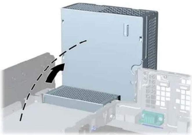
- Disconnect the power cable (1) and data cable (2) from the back of the hard drive.
Figure 3-35 Disconnecting the Hard Drive Cables

- Press down on the green release latch next to the hard drive (1). While holding the latch down, slide the drive forward until it stops, then lift the drive up and out of the bay (2).
Figure 3-36 Removing the Hard Drive

- To install a hard drive, you must transfer the silver and blue isolation mounting guide screws from the old hard drive to the new hard drive.
Figure 3-37 Installing Hard Drive Guide Screws

- Align the guide screws with the slots on the chassis drive cage, press the hard drive down into the bay, then slide it back until it stops and locks in place.
Figure 3-38 Installing the Hard Drive

- Connect the power cable (1) and data cable (2) to the back of the hard drive.
NOTE: If the system has only one SATA hard drive, the data cable must be connected to the dark blue connector labeled SATA0 on the system board to avoid any hard drive performance problems.
Figure 3-39 Connecting the Hard Drive Cables

- Rotate the drive cage for internal drives and the power supply down to their normal positions.
- Replace the access panel.
- If the computer was on a stand, replace the stand.
- Reconnect the power cord and turn on the computer.
- Lock any security devices that were disengaged when the access panel was removed.
Installing a Security Lock
The security locks displayed below and on the following pages can be used to secure the computer.
Cable Lock
Figure 3-40 Installing a Cable Lock

Padlock
Figure 3-41 Installing a Padlock

HP Business PC Security Lock
- Fasten the security cable by looping it around a stationary object.
Figure 3-42 Securing the Cable to a Fixed Object

- Insert the Cable lock into the Cable lock slot on the back of the monitor and secure the lock to the monitor by inserting the key into the key hole on the rear of the lock and rotating the key 90 degrees.
Figure 3-43 Installing the Cable Lock on the Monitor

- Slide the security cable through the hole in the Cable lock on the rear of the monitor.
Figure 3-44 Securing the Monitor
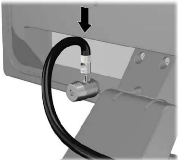
- Use the bracket provided in the kit to secure other peripheral devices by laying the device cable across the center of the bracket (1) and inserting the security cable through one of the two holes in the bracket (2). Use the hole in the bracket that best secures the peripheral device cable.
Figure 3-45 Securing Peripheral Devices (Printer Shown)

- Thread the keyboard and mouse cables through the computer chassis lock.
Figure 3-46 Threading the Keyboard and Mouse Cables

- Screw the lock to the chassis in the thumbscrew hole using the screw provided.
Figure 3-47 Attaching the Lock to the Chassis

- Insert the plug end of the security cable into the lock (1) and push the button in (2) to engage the lock. Use the key provided to disengage the lock.
Figure 3-48 Engaging the Lock

- When complete, all devices in your workstation will be secured.
Figure 3-49 Secured Workstation

Front Bezel Security
The front bezel can be locked in place by installing a security screw provided by HP. To install the security screw:
- Remove/disengage any security devices that prohibit opening the computer.
- Remove all removable media, such as compact discs or USB flash drives, from the computer.
- Turn off the computer properly through the operating system, then turn off any external devices.
- Disconnect the power cord from the power outlet and disconnect any external devices.
CAUTION: Regardless of the power-on state, voltage is always present on the system board as long as the system is plugged into an active AC outlet. You must disconnect the power cord to avoid damage to the internal components of the computer.
-
If the computer is on a stand, remove the computer from the stand.
-
Remove the access panel and front bezel.
-
Remove one of the five silver 6-32 standard screws located on the front of the chassis behind the bezel.
Figure 3-50 Retrieving the Front Bezel Security Screw

-
Replace the front bezel.
-
Install the security screw next to the middle front bezel release tab to secure the front bezel in place.
Figure 3-51 Installing the Front Bezel Security Screw

- Replace the access panel.
- If the computer was on a stand, replace the stand.
- Reconnect the power cord and turn on the computer.
- Lock any security devices that were disengaged when the access panel was removed.
A Battery Replacement
The battery that comes with the computer provides power to the real-time clock. When replacing the battery, use a battery equivalent to the battery originally installed in the computer. The computer comes with a 3-volt lithium coin cell battery.
WARNING! The computer contains an internal lithium manganese dioxide battery. There is a risk of fire and burns if the battery is not handled properly. To reduce the risk of personal injury:
Do not attempt to recharge the battery.
Do not expose to temperatures higher than 60° C ( 140° F).
Do not disassemble, crush, puncture, short external contacts, or dispose of in fire or water.
Replace the battery only with the HP spare designated for this product.
CAUTION: Before replacing the battery, it is important to back up the computer CMOS settings. When the battery is removed or replaced, the CMOS settings will be cleared.
Static electricity can damage the electronic components of the computer or optional equipment. Before beginning these procedures, ensure that you are discharged of static electricity by briefly touching a grounded metal object.
NOTE: The lifetime of the lithium battery can be extended by plugging the computer into a live AC wall socket. The lithium battery is only used when the computer is NOT connected to AC power.
HP encourages customers to recycle used electronic hardware, HP original print cartridges, and rechargeable batteries. For more information about recycling programs, go to http://www.hp.com/recycle.
- Remove/disengage any security devices that prohibit opening the computer.
- Remove all removable media, such as compact discs or USB flash drives, from the computer.
- Turn off the computer properly through the operating system, then turn off any external devices.
- Disconnect the power cord from the power outlet and disconnect any external devices.
CAUTION: Regardless of the power-on state, voltage is always present on the system board as long as the system is plugged into an active AC outlet. You must disconnect the power cord to avoid damage to the internal components of the computer.
-
Remove the computer access panel.
-
Locate the battery and battery holder on the system board.
NOTE: On some computer models, it may be necessary to remove an internal component to gain access to the battery.
- Depending on the type of battery holder on the system board, complete the following instructions to replace the battery.
Type 1
a. Lift the battery out of its holder.
Figure A-1 Removing a Coin Cell Battery (Type 1)

b. Slide the replacement battery into position, positive side up. The battery holder automatically secures the battery in the proper position.
Type 2
a. To release the battery from its holder, squeeze the metal clamp that extends above one edge of the battery. When the battery pops up, lift it out (1).
b. To insert the new battery, slide one edge of the replacement battery under the holder's lip with the positive side up. Push the other edge down until the clamp snaps over the other edge of the battery (2).
Figure A-2 Removing and Replacing a Coin Cell Battery (Type 2)
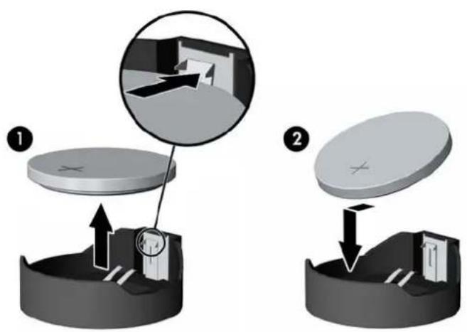
Type 3
a. Pull back on the clip (1) that is holding the battery in place, and remove the battery (2).
b. Insert the new battery and position the clip back into place.
Figure A-3 Removing a Coin Cell Battery (Type 3)


NOTE: After the battery has been replaced, use the following steps to complete this procedure.
- Replace the computer access panel.
- Plug in the computer and turn on power to the computer.
- Reset the date and time, your passwords, and any special system setups using Computer Setup.
- Lock any security devices that were disengaged when the computer access panel was removed.
B Removing and Replacing a Removable 3.5-inch SATA Hard Drive
Some models are equipped with a Removable SATA Hard Drive Enclosure in the 5.25-inch internal drive bay. The hard drive is housed in a carrier that can be quickly and easily removed from the drive bay. To remove and replace a drive in the carrier:

NOTE: Before you remove the old hard drive, be sure to back up the data from the old hard drive so that you can transfer the data to the new hard drive.
- Unlock the hard drive carrier with the key provided and slide the carrier out of the enclosure.
- Remove the screw from the rear of the carrier (1) and slide the top cover off the carrier (2).
Figure B-1 Removing the Carrier Cover
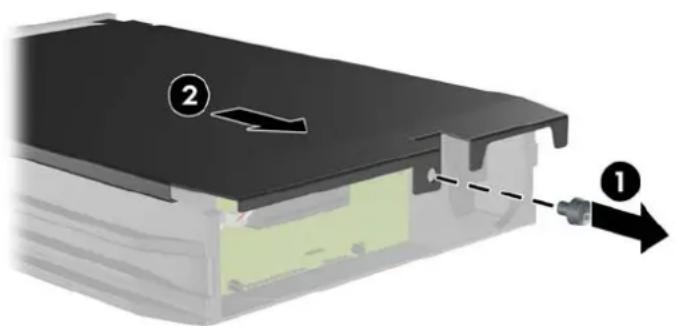
- Remove the adhesive strip that secures the thermal sensor to the top of the hard drive (1) and move the thermal sensor away from the carrier (2).
Figure B-2 Removing the Thermal Sensor

- Remove the four screws from the bottom of the hard drive carrier.
Figure B-3 Removing the Security Screws

- Slide the hard drive back to disconnect it from the carrier then lift it up and out of the carrier.
Figure B-4 Removing the Hard Drive

- Place the new hard drive in the carrier then slide the hard drive back so that it seats in the SATA connector on the carrier's circuit board. Be sure the connector on the hard drive is pressed all the way into the connector on the carrier's circuit board.
Figure B-5 Replacing the Hard Drive
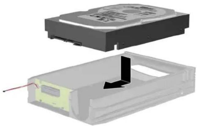
- Replace the four screws in the bottom of the carrier to hold the drive securely in place.
Figure B-6 Replacing the Security Screws

- Place the thermal sensor on top of the hard drive in a position that does not cover the label (1) and attach the thermal sensor to the top of the hard drive with the adhesive strip (2).
Figure B-7 Replacing the Thermal Sensor

- Slide the cover on the carrier (1) and replace the screw on the rear of the carrier to secure the cover in place (2).
Figure B-8 Replacing the Carrier Cover

- Slide the hard drive carrier into the enclosure on the computer and lock it with the key provided.

NOTE: The carrier must be locked for power to be supplied to the hard drive.
C Unlocking the Smart Cover Lock

NOTE: The Smart Cover Lock is an optional feature included on some models only.
The Smart Cover Lock is a software-controllable cover lock, controlled by the setup password. This lock prevents unauthorized access to the internal components. The computer ships with the Smart Cover Lock in the unlocked position. For more information about locking the Smart Cover Lock, refer to the Desktop Management Guide.
Smart Cover FailSafe Key
If you enable the Smart Cover Lock and cannot enter your password to disable the lock, you will need a Smart Cover FailSafe Key to open the computer cover. You will need the key to access the internal computer components in any of the following circumstances:
Power outage
- Startup failure
• PC component (for example, processor or power supply) failure
• Forgotten password

NOTE: The Smart Cover FailSafe Key is a specialized tool available from HP. Be prepared; order this key before you need it.
To obtain a FailSafe Key:
- Contact an authorized HP reseller or service provider. Order PN 166527-001 for the wrench-style key or PN 166527-002 for the screwdriver bit key.
• Refer to the HP Web site (http://www.hp.com) for ordering information. - Call the appropriate number listed in the warranty or in the Support Telephone Numbers guide.
Using the Smart Cover FailSafe Key to Remove the Smart Cover Lock
To open the access panel with the Smart Cover Lock engaged:
- Remove/disengage any security devices that prohibit opening the computer.
- Remove all removable media, such as compact discs or USB flash drives, from the computer.
-
Turn off the computer properly through the operating system, then turn off any external devices.
-
Disconnect the power cord from the power outlet and disconnect any external devices.

CAUTION: Regardless of the power-on state, voltage is always present on the system board as long as the system is plugged into an active AC outlet. You must disconnect the power cord to avoid damage to the internal components of the computer.
- Use the Smart Cover FailSafe Key to remove the two tamper-proof screws that secure the Smart Cover Lock to the chassis.
Figure C-1 Removing the Smart Cover Lock Screws from the Microtower

Figure C-2 Removing the Smart Cover Lock Screws from the Small Form Factor

You can now remove the access panel.
To reattach the Smart Cover Lock, secure the lock in place with the tamper-proof screws.
D Electrostatic Discharge
A discharge of static electricity from a finger or other conductor may damage system boards or other static-sensitive devices. This type of damage may reduce the life expectancy of the device.
Preventing Electrostatic Damage
To prevent electrostatic damage, observe the following precautions:
- Avoid hand contact by transporting and storing products in static-safe containers.
- Keep electrostatic-sensitive parts in their containers until they arrive at static-free workstations.
- Place parts on a grounded surface before removing them from their containers.
- Avoid touching pins, leads, or circuitry.
• Always be properly grounded when touching a static-sensitive component or assembly.
Grounding Methods
There are several methods for grounding. Use one or more of the following methods when handling or installing electrostatic-sensitive parts:
- Use a wrist strap connected by a ground cord to a grounded workstation or computer chassis. Wrist straps are flexible straps with a minimum of 1 megohm +/- 10 percent resistance in the ground cords. To provide proper ground, wear the strap snug against the skin.
- Use heelstraps, toestraps, or bootstraps at standing workstations. Wear the straps on both feet when standing on conductive floors or dissipating floor mats.
• Use conductive field service tools.
• Use a portable field service kit with a folding static-dissipating work mat.
If you do not have any of the suggested equipment for proper grounding, contact an HP authorized dealer, reseller, or service provider.

NOTE: For more information on static electricity, contact an HP authorized dealer, reseller, or service provider.
E Computer Operating Guidelines, Routine Care and Shipping Preparation
Computer Operating Guidelines and Routine Care
Follow these guidelines to properly set up and care for the computer and monitor:
- Keep the computer away from excessive moisture, direct sunlight, and extremes of heat and cold.
- Operate the computer on a sturdy, level surface. Leave a 10.2-cm (4-inch) clearance on all vented sides of the computer and above the monitor to permit the required airflow.
- Never restrict the airflow into the computer by blocking any vents or air intakes. Do not place the keyboard, with the keyboard feet down, directly against the front of the desktop unit as this also restricts airflow.
- Never operate the computer with the access panel or any of the expansion card slot covers removed.
- Do not stack computers on top of each other or place computers so near each other that they are subject to each other's re-circulated or preheated air.
- If the computer is to be operated within a separate enclosure, intake and exhaust ventilation must be provided on the enclosure, and the same operating guidelines listed above will still apply.
- Keep liquids away from the computer and keyboard.
- Never cover the ventilation slots on the monitor with any type of material.
• Install or enable power management functions of the operating system or other software, including sleep states.
• Turn off the computer before you do either of the following:
Wipe the exterior of the computer with a soft, damp cloth as needed. Using cleaning products may discolor or damage the finish.
Occasionally clean the air vents on all vented sides of the computer. Lint, dust, and other foreign matter can block the vents and limit the airflow.
Optical Drive Precautions
Be sure to observe the following guidelines while operating or cleaning the optical drive.
Operation
- Do not move the drive during operation. This may cause it to malfunction during reading.
- Avoid exposing the drive to sudden changes in temperature, as condensation may form inside the unit. If the temperature suddenly changes while the drive is on, wait at least one hour before you turn off the power. If you operate the unit immediately, it may malfunction while reading.
- Avoid placing the drive in a location that is subject to high humidity, extreme temperatures, mechanical vibration, or direct sunlight.
Cleaning
- Clean the panel and controls with a soft, dry cloth or a soft cloth lightly moistened with a mild detergent solution. Never spray cleaning fluids directly on the unit.
- Avoid using any type of solvent, such as alcohol or benzene, which may damage the finish.
Safety
If any object or liquid falls into the drive, immediately unplug the computer and have it checked by an authorized HP service provider.
Shipping Preparation
Follow these suggestions when preparing to ship the computer:
- Back up the hard drive files on PD discs, tape cartridges, CDs, or USB flash drives. Be sure that the backup media is not exposed to electrical or magnetic impulses while stored or in transit.

NOTE: The hard drive locks automatically when the system power is turned off.
-
Remove and store all removable media.
-
Turn off the computer and external devices.
-
Disconnect the power cord from the electrical outlet, then from the computer.
-
Disconnect the system components and external devices from their power sources, then from the computer.

NOTE: Ensure that all boards are seated properly and secured in the board slots before shipping the computer.
- Pack the system components and external devices in their original packing boxes or similar packaging with sufficient packing material to protect them.
Index
A
access panel
locking and unlocking 90
MT removal 12
MT replacement 13
SFF removal 45
SFF replacement 46
B
battery replacement 82
C
computer operating guidelines 93
D
DIMMs. See memory
drives
MT cable connections 25
MT installation 25
MT locations 24
SFF cable connections 60
SFF installation 60
SFF locations 59
E
electrostatic discharge, preventing damage 92
expansion card
MT installation 20
MT removal 20
SFF installation 55
SFF removal 55
expansion slot cover
MT removal 21
SFF removal 56
F
FailSafe Key 90
front bezel
MT blank removal 14
MT removal 14
MT replacement 15
MT security 42
SFF blank removal 47
SFF removal 47
SFF replacement 48
SFF security 80
front panel components
MT 2
SFF 3
G
guide screws
MT location 25
SFF location 60
H
hard drive
MT installation 33
MT removal 32
SFF installation 71
SFF removal 71
I
installation guidelines 11, 44
installing
battery 82
MT drive cables 25
MT expansion card 20
MT hard drive 33
MT media card reader 29
MT memory 17
MT optical drive 29
SFF drive cables 60
SFF expansion card 55
SFF hard drive 71
SFF media card reader 69
SFF memory 51
SFF optical drive 64
K
keyboard
components 7
Windows Logo key 8
L
locks
MT front bezel 42
MT HP Business PC Security
Lock 38
MT padlock 37
SFF cable lock 37, 75
SFF front bezel 80
SFF HP Business PC Security
Lock 76
SFF padlock 75
Smart Cover Lock 90
M
media card reader
features 6
MT installation 29
MT removal 27
SFF installation 69
SFF removal 67
memory
MT installation 17
MT socket population 17
MT specifications 17
SFF installation 51
SFF socket population 51
SFF specifications 51
0
optical drive
cleaning 94
MT installation 29
MT removal 27
precautions 94
SFF installation 64
SFF removal 62
P
product ID locations 9
R
rear panel components
MT 4
SFF 5
removing
battery 82
MT bezel blanks 14
MT computer access panel 12
MT expansion card 20
MT expansion slot cover 21
MT front bezel 14
MT hard drive 32
MT media card reader 27
MT optical drive 27
SFF bezel blanks 47
SFF computer access panel 45
SFF expansion card 55
SFF expansion slot cover 56
SFF front bezel 47
SFF hard drive 71
SFF media card reader 67
SFF optical drive 62
Smart Cover Lock 90
S
security
MT front bezel 42
MT HP Business PC Security Lock 38
MT padlock 37
SFF cable lock 37, 75
SFF front bezel 80
SFF HP Business PC Security Lock 76
SFF padlock 75
Smart Cover Lock 90
serial number locations 9
shipping preparation 94
Smart Cover Lock 90
specifications
MT memory 17
SFF memory 51
system board connections
MT 16
SFF 50
T
tower conversion
SFF 49
U
unlocking access panel 90
V
ventilation guidelines 93
W
Windows Logo key 8

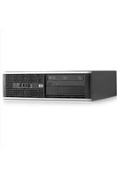


- HP COMPAQ BUSINESS PC HARDWARE REFERENCE GUIDE
- ABOUT THIS BOOK
- TABLE OF CONTENTS
- 1 PRODUCT FEATURES .... 1
- 2 MICROTOWER (MT) HARDWARE UPGRADES 11
- 3 SMALL FORM FACTOR (SFF) HARDWARE UPGRADES 44
- APPENDIX A BATTERY REPLACEMENT 82
- APPENDIX B REMOVING AND REPLACING A REMOVABLE 3.5-INCH SATA HARD DRIVE 85
- APPENDIX C UNLOCKING THE SMART COVER LOCK 90
- APPENDIX D ELECTROSTATIC DISCHARGE 92
- APPENDIX E COMPUTER OPERATING GUIDELINES, ROUTINE CARE AND SHIPPING PREPARATION 93
- INDEX 95
- 1 PRODUCT FEATURES
- STANDARD CONFIGURATION FEATURES
- MICROTOWER (MT) FRONT PANEL COMPONENTS
- SMALL FORM FACTOR (SFF) FRONT PANEL COMPONENTS
- MICROTOWER (MT) REAR PANEL COMPONENTS
- SMALL FORM FACTOR (SFF) REAR PANEL COMPONENTS
- MEDIA CARD READER COMPONENTS
- KEYBOARD
- USING THE WINDOWS LOGO KEY
- SERIAL NUMBER LOCATION
- 2 MICROTOWER (MT) HARDWARE UPGRADES
- SERVICEABILITY FEATURES
- WARNINGS AND CAUTIONS
- REMOVING THE COMPUTER ACCESS PANEL
- REPLACING THE COMPUTER ACCESS PANEL
- REMOVING THE FRONT BEZEL
- REMOVING BEZEL BLANKS
- REPLACING THE FRONT BEZEL
- SYSTEM BOARD CONNECTIONS
- INSTALLING ADDITIONAL MEMORY
- DIMMS
- DDR3-SDRAM DIMMS
- POPULATING DIMM SOCKETS
- INSTALLING DIMMS
- REMOVING OR INSTALLING AN EXPANSION CARD
- DRIVE POSITIONS
- INSTALLING AND REMOVING DRIVES
- NO. GUIDE SCREW DEVICE
- REMOVING A 5.25-INCH OR 3.5-INCH DRIVE FROM A DRIVE BAY
- INSTALLING A 5.25-INCH OR 3.5-INCH DRIVE INTO A DRIVE BAY
- REMOVING A HARD DRIVE FROM A DRIVE BAY
- INSTALLING A HARD DRIVE INTO AN INTERNAL DRIVE BAY
- INSTALLING A SECURITY LOCK
- CABLE LOCK
- PADLOCK
- HP BUSINESS PC SECURITY LOCK
- FRONT BEZEL SECURITY
- 3 SMALL FORM FACTOR (SFF) HARDWARE UPGRADES
- CHANGING FROM DESKTOP TO TOWER CONFIGURATION
- REMOVING A 5.25-INCH DRIVE FROM A DRIVE BAY
- INSTALLING A 5.25-INCH DRIVE INTO A DRIVE BAY
- REMOVING A 3.5-INCH DRIVE FROM A DRIVE BAY
- INSTALLING A 3.5-INCH DRIVE INTO A DRIVE BAY
- REMOVING AND REPLACING THE PRIMARY 3.5-INCH INTERNAL HARD DRIVE
- A BATTERY REPLACEMENT
- TYPE 1
- TYPE 2
- TYPE 3
- B REMOVING AND REPLACING A REMOVABLE 3.5-INCH SATA HARD DRIVE
- C UNLOCKING THE SMART COVER LOCK
- SMART COVER FAILSAFE KEY
- USING THE SMART COVER FAILSAFE KEY TO REMOVE THE SMART COVER LOCK
- D ELECTROSTATIC DISCHARGE
- PREVENTING ELECTROSTATIC DAMAGE
- GROUNDING METHODS
- E COMPUTER OPERATING GUIDELINES, ROUTINE CARE AND SHIPPING PREPARATION
- COMPUTER OPERATING GUIDELINES AND ROUTINE CARE
- OPTICAL DRIVE PRECAUTIONS
- OPERATION
- CLEANING
- SAFETY
- SHIPPING PREPARATION
- INDEX
- A
- B
- C
- D
- E
- F
- G
- H
- I
- K
- L
- M
- 0
- P
- R
- S
- T
- U
- V
- W
Brand : COMPAQ
Model : Pro 6305 SFF
Category : Desktop computer