Tx2-1600 - Printer Mimaki - Free user manual and instructions
Find the device manual for free Tx2-1600 Mimaki in PDF.


| Product Type | Dye-Sublimation Printer |
| Brand | Mimaki |
| Model | Tx2-1600 |
| Print Technology | Piezo inkjet |
| Max Print Width | 1620 mm |
| Resolution | Up to 1200 dpi |
| Ink Type | Sublimation ink (Sb53) |
| Number of Print Heads | 2 x 8-channel |
| Media Handling | Roll-to-roll |
| Dimensions (W x D x H) | 2700 x 1000 x 1500 mm |
| Weight | Approx. 500 kg |
| Power Supply | AC 100-120V / 200-240V, 50/60Hz |
| Power Consumption | Approx. 1.5 kW (heater) |
| Interface | USB, Ethernet |
| Operating Temperature | 15-30°C |
| Humidity Range | 35-65% RH |
| Safety Certifications | CE, UL |
| Maintenance Tasks | Regular cleaning, wiper replacement |
| Repairability | Print head replacement, maintenance kit |
| Included Accessories | Printer, stand, software |
Frequently Asked Questions - Tx2-1600 Mimaki
User questions about Tx2-1600 Mimaki
0 question about this device. Answer the ones you know or ask your own.
Ask a new question about this device
Download the instructions for your Printer in PDF format for free! Find your manual Tx2-1600 - Mimaki and take your electronic device back in hand. On this page are published all the documents necessary for the use of your device. Tx2-1600 by Mimaki.
USER MANUAL Tx2-1600 Mimaki
natural_image
Technical line drawing of a large industrial printer or printer with no visible text or symbolsMIMAKI ENGINEERING CO., LTD.
TKB Gotenyama Building, 5-9-41, Kitashinagawa, Shinagawa-ku, Tokyo 141-0001, Japan
Phone: +81-3-5420-8671 Fax: +81-3-5420-8687
The kinds of manuals and how to use them
The following documents have been attached to Tx2-1600:
Operation Manual (this document)
"Operation Manual" explains how to operate Tx2-1600.
Ink - UseGuidance (separate volume)
"Ink - Use Guidance" explains recommended recipe of pre and post fabric treatment according to each ink.
Foreword
Thank you for purchasing MIMAKI Textile Jet Tx2-1600.
Model Tx2-1600 is a color inkjet printer for printing on fabric with eight colors at high speeds. This operation manual describes the operation and maintenance of modelTx2-1600 Color InkJet Printer (hereinafter referred to as the printer).
Read this manual carefully and make the most effective use of your printer.
DISCLAIMER OF WARRANTY
THIS LIMITED WARRANTY OF MIMAKI SHALL BE THE SOLE AND EXCLUSIVE WARRANTY AND IS IN LIEU OF ALL OTHER WARRANTIES, EXPRESS OR IMPLIED, INCLUDING, BUT NOT LIMITED TO, ANY IMPLIED WARRANTY OF MERCHANTABILITY OR FITNESS, AND MIMAKI NEITHER ASSUMES NOR AUTHORIZES DEALER TO ASSUME FOR IT ANY OTHER OBLIGATION OR LIABILITY OR MAKE ANY OTHER WARRANTY OR MAKE ANY OTHER WARRANTY IN CONNECTION WITH ANY PRODUCT WITHOUT MIMAKI'S PRIOR WRITTEN CONSENT. IN NO EVENT SHALL MIMAKI BE LIABLE FOR SPECIAL, INCIDNETAL OR CONSEQUENTIAL DAMAGES OR FOR LOSS OF PROFITS OF DEALER OR CUSTOMERS OF ANY PRODUCT.
On this Operation Manual
- The printer is equipped with a high speed print head and other high performance part that may be dangerous.
Please be sure to read this manual carefully before starting this printer operation in order to prevent the injuries or damages. - Please read and fully understand this Operation Manual before putting the printer into service. It is also necessary to keep this Operation Manual on hand.
- This Operation Manual has been carefully prepared for your easy understanding, however, please do not hesitate to contact a distributor in your district if you have any inquiry.
- Description contained in this Operation Manual are subject to change without notice for improvement.
- In the case where this Operation Manual should be illegible due to destruction by fire or breakage, purchase another copy of the Operation Manual from our distributor.
- Generally, names and designations referred to in this Operation Manual are trade marks or registered trade marks of the manufacturers or suppliers.
FCC Statement (USA)
This equipment has been tested and found to comply with the limits for a Class A digital device, pursuant to Part 15 of the FCC Rules. These limits are designed to provide reasonable protection against harmful interference when the equipment is operated in a commercial environment. This equipment generates, uses and can radiate radio frequency energy and, if not installed and used in accordance with the instruction manual, may cause harmful interference to radio communications.
Operation of this equipment in a residential area is likely to cause harmful interference in which cause the user will be required to correct the interference at his own expense.

- In the case where MIMAKI-recommended cable is not used for connection of this printer, limits provided by FCC rules can be exceeded. To prevent this, use of MIMAKI-recommended cable is essential for the connection of this printer.
Interference to televisions and radios
The product covered by this Operation Manual produces low radio waves while it is in operation. The product can interfere with radios and televisions if set up or commissioned under improper conditions. The product is not guaranteed against any damage to specific-purpose radio and televisions.
The product's interference with your radio or television will be checked by turning on/off the power switch of the product.
In the event that the product is the cause of interference, try to eliminate it by taking one of the following corrective measures or taking some of them in combination.
- Change the direction of the receiving antenna or the feeder of your radio/television.
- Change the installing direction of the product.
- Move the receiver away from the product.
- Use a power line for the receiver that is not shared with the product.
TABLE OF CONTENTS
Foreword ...... i
DISCLAIMER OF WARRANTY.... i
On this Operation Manual .... i
FCC Statement (USA) ......ii
Interference to televisions and radios ....ii
Features......viii
How to read this Operation Manual .... x
Safety symbols used in this Manual....xii
Structure of this Manual ....xiii
For safe operation....xiv
Warnings in use ....xiv
Precautions in use ....xiv
Position of the warning label ...... xv
Chapter 1 Setup
Installation of the printer 1.2
Where to install the printer 1.2
Precautions in installation 1.3
Checking the accessories 1.4
Unpacking and Assembling.... 1.6
Assembling the stand and the device 1.6
Attaching take-up auxiliary bar 1.9
Attaching loading auxiliary bar 1.9
Attaching centering sensor unit.... 1.10
Attaching loading unit 1.10
Connecting connectors and cables 1.10
How to remove the stopper 1.11
Putting on the maintenance cover 1.11
Attach the waste ink hoses. 1.12
Attaching slip sheet bar 1.12
Preparing the waste ink tank 1.12
Configuration and Fction 1.13
Front face 1.13
Rear face 1.14
Names and function of the parts under the front cover 1.15
Carriage 1.15
Capping station 1.16
The pinch roller and feed roller 1.16
The media sensor 1.17
Head hight adjustment rod and adjustment screw 1.17
Fabic retainer 1.18
Ditch for penetrated ink and platen boards 1.19
About other setup....1.20
Attaching lapel bar 1.20
Attaching the platen boards 1.22
Changing gap for fabic retainers 1.23
Installing IEEE1394 output driver.... 1.23
Connecting the cables 1.24
Connecting the interface cable 1.24
Connecting the power cable 1.25
Switching ON/OFF the power supply 1.26
Turning the power on 1.26
Turning the power off 1.27
Front cover and maintenance cover 1.28
Opening/closing the cover 1.28
Ink cartridges 1.29
Types of ink 1.29
Precautions in handling the ink cartridge 1.29
Ink stations 1.30
Display of ink type 1.31
Setting ink cartridges 1.32
Fabric for printing 1.34
Types of fabic that can be used 1.34
Precautions in handling the fabric 1.35
Limited media 1.35
Before setting the fabric on the printer 1.36
Adjusting the head height according to the fabic [HEAD HEIGHT].... 1.36
Points in head height adjustment 1.39
Setting the mating sheet 1.40
Adjusting parallelism of loading unit.... 1.40
Setting The FabricTo The Printer 1.41
Setting a roll fabic 1.41
Setting the centering sensor position 1.45
Attaching empty fabic core for taking up 1.46
Removing pinch roller and preventing wrinkle of fabic 1.47
Specifying the scope of printing on the fabric used (Effective printing area) 1.49
Origin setting 1.50
Setting of an origin 1.50
Moving the printer 1.51
Chapter 2 How to use the basic functions
Operation 2.2
Operation panel 2.2
Functions of the JOG keys.... 2.3
MENU mode 2.3
Menu tree 2.4
Setting the display language 2.6
Printing an image from source data 2.7
Starting the printer operation 2.7
Correcting the media feed rate during printing [Feed Comp.] 2.9
Interrupting the printing operation 2.10
Checking nozzle in ink firing condition 2.11
Executing the test draw [TEST DRAW] 2.11
Checking the test patterns 2.11
If there are nozzle clogging in ink firing condition 2.12
Cleaning ink heads 2.12
Routine maintenance 2.13
When the device is left unused for a long period of time 2.13
Notes on cleaning 2.13
Cleaning ink at the bottom of the slider 2.13
Cleaning wiper 2.13
Cleaning the wiper shaft 2.14
Maintenance for frame components 2.14
Cleaning penetrated ink 2.14
To replenish ink, set a new ink cartridge in the ink station 2.15
Chapter 3 How to use the application functions
Application functions 3.2
Function menu 3.2
Before setting printing conditions in the function menu 3.3
Checking the menu mode 3.3
Registering Two or More Printing Conditions at a Time (Selecting a Type) 3.3
Changing the type 3.4
Adjusting the lapal bar 3.5
Troubleshooting 3.6
After setting the fabric to be printed 3.7
Correcting error of amount of feed depending on fabric [MEDIA COMP.] 3.7
Setting printing conditions 3.8
Changing printing conditions on the printer side 3.8
Relationship between image quality and printing speed [QUALITY] 3.8
Printing direction [DIRECTION] 3.9
Returning speed up [RET. SPD UP] 3.10
Improving the density of ink color [INK LAYERS] 3.11
Setting the ink drying time [DRYING TIME] 3.12
Deciding the priority of settings by the computer or the plotter [PRIORITY] ...... 3.13
Increasing (decreasing) the right and left margins of the fabric [RIGHTmargin]/
[LEFTmargin] 3.15
Setting [RIGHTmargin] 3.15
Setting [LEFTmargin] 3.16
When using the plotter in an extremely dusty or dry place [REFRESH] 3.17
Setting a unit of length displayed on the LCD [MM/INCH] 3.18
Setting the type of ink to be used [INK TYPE] 3.19
Setting up auto-cleaning function [AUTO CLEAN]....3.20
Setting up auto-cleaning function [AUTO CLEAN2].... 3.21
Back feed Setting for End of printing [EndOf PRINT] 3.23
Continuing printing after [Ink Near End] [PRINT CONT.] 3.24
Preventing the fabric skew [CENTERING].... 3.25
Enabling the take-up unit [TAKE-UP] 3.26
Resetting printing conditions by type [SETUP RESET] 3.27
Chapter 4 Maintenance functions
Maintenance of the printer 4.2
Function menu [MAINTENANCE] 4.2
Before starting maintenance 4.3
Checking the menu mode 4.3
Invoking a maintenance function 4.3
Maintenance functions 4.4
Drawing setup conditions [LIST] 4.4
Printing HEX code of printing command [DATA DUMP] 4.5
Correcting the dot positions after adjusting the head height [PRINTadjust] 4.6
Moving the carriage to clean the station interior [CARRIAGEout] 4.8
If a defective printing is not corrected even after the cleaning function is executed ..... 4.9
Periodical cleaning of the wiper 4.10
Notes on handling the wipers.... 4.10
When the message [Replace Wiper] is displayed [WIPER EXCHG] 4.11
When the message [Clean Wiper Shaft] is displayed 4.13
Cleaning the nozzle [NOZZLE CLN] 4.14
Ink discharge way cleaning [DRAIN WASH] 4.17
When not in use the machine over the long term [STORAGE WSH] 4.19
Move the carriage to the left maintenance station [CARRIAGE] 4.23
Adjusting the head height when the fabric used is changed [HEAD HEIGHT] 4.24
Menu displayed after the ink cartridge is installed [FILL UP INK] 4.25
When charging ink different from the one in use [INK CHANGE] 4.26
Selecting ink head [USE HEAD] 4.29
Check the stretch and shrink of fabric after the printing [STRETCH CHK] 4.30
Displaying the printer information [INFORMATION] 4.32
Chapter 5 When abnormal conditions are encountered
Before taking a phenomenon as a sign of failure.... 5.2
The printer cannot be energized 5.2
The printer cannot perform printing 5.2
Paper jamming arises/fabric is soiled 5.3
If image quality declines.... 5.4
White lines/thin spots are obvious (In the direction of travel of the head)....5.4
Displacement is observed between outward and inward printing 5.4
The respective color ink injected by the respective color heads do not properly overlap 5.4
Troubles for which error message are given on the LCD 5.5
Warning message 5.5
Error messages....5.7
Appendix
Basic specifications....A.2
Ink Specification....A.3
Optional extras....A.4
Function flow chart....A.5
Features
The features and methods of operation are explained in this manual for you to understand how to use the printer properly.
Setting for 2-way multi printing
Alternatively, using two sets of three heads in 2-way printing mode, each with different inks, gives you the functionality of two 8-color printers in a single unit.
3 types of textile printing ink can be used
MIMAKI genuine ink is shown below.
Acid dye ink : Suitable for wool, silk, and other animal fibers and nylon.
Disperse dye ink : Suitable for polyester, acrylic, etc.
Reactive dye ink : Suitable for wool, silk in addition to cotton, rayon, etc.
- When using any type of ink, be sure to perform the pre-processing and post-processing recommended by MIMAKI for the fabric used.
Applicability of fabrics up to 7mm in thickness
Even thick fabric can be used.
The printer accepts fabric whose thickness is in the range of 0.1mm to 7.0mm.
Applicable to wide fabrics
Fabrics with up to 1650mm width can be set and printing for up to 1620mm width is possible.
Indication of the amount of remaining ink
The IC chip mounted on the ink cartridge allows monitoring of the amount of remaining ink even after it is removed and remounted.
This avoids INK END during unattended operation, allowing efficient use of ink and fabric.
Easy-to-see display
The LCD panel displays the printer setting menu in two lines making it is easy to see.
Since the LCD panel is provided with a backlight, the display can be clearly seen even in a dark place.
The LCD panel is capable of displaying six different languages, including English and Spanish.
Display of information for confirmation
It is possible to have the printing length displayed on the LCD panel and the printing conditions to be plotted for confirmation during operation of the printer.
High-speed interface
The "IEEE 1394" interface allows for high-speed data reception from the computer.
Fabric retainer
If the edge of the fabric is curled or it is raised, the fabric retainer can be used to avoid contact of the fabric and ink head.
The fabric retainer can be adjusted thickness of up to 4 mm and 3-7 mm.
Ditch for penetrated ink
Even with printing to a coarse-textured fabric, the backing fabric is not stained by penetrated ink.
Removable platen boards are prepared for fabrics without ink penetration.
Slip sheet can be used
One set of slip sheet bar and its hanger is equipped as standard.
It can be used for slip sheet between fabric with take-up unit to prevent ink penetration.
Function of feed-correction
Feed correction can be performed during plotting operation.
Centering (anti-meandering) mechanism
Stable fabric feed and printing are possible even if the edge of the set roll fabric is not aligned.
Display on the LCD and indication of the keys
In this Operation Manual, the characters displayed on the LCD of the operation panel and the keys used to operate the printer are explained, together with the operation procedure.
(See page 2.2)
Operate the printer while confirming the display on the LCD.
Display on the LCD
The content of display is shown in characters in a box as shown at right.
Operate the printer according to the explanation of the operation procedure and the content of display on the LCD.
In this Operation Manual, each setting and messages displayed on the LCD is enclosed in [ ], such as [TYPE.1], [Reac], [PLEASE WAIT], etc.
FUNCTION
SET UP
SET UP SELECT : TYPE.1
Operation keys
In the text of this Operation Manual, the operation keys are shown enclosed in brackets.
[ʌnd [ ]▼ indicate JOG keys.
The other operation keys are enclosed in brackets, as [FUNCTION]. (See page 2.3.)
How to read this Operation Manual
![The title in each chapter are provided. Notes to sentences, caution on plotter operation, and hints for effective use of the plotter are given. This manual describes the procedure of operation of the plotter. Setting the type of ink to be used [INK TYPE] This function selects the type of ink that is to be used. When starting an actual printing operation, however, select only one type of ink to be used according to the printing data and the fabric used. This function can be used when different types of ink are loaded in the plotter. As the ink that can be specified, select from the types of ink that have been set in the ink stations. Sub : Sublimation dye ink TPig : Textile pigment ink NOTE: If the same type of ink is set in the ink stations on both sides, the type of ink cannot be set since [INK TYPE] is not displayed on the LCD. STEPS: 1. Select a type. (See page 3.4) Here, select [Type 1]. 2. Press the [ENTER] key. 3. Press the JOG keys [▲] and [▼] to select [INKTYPE]. 4. Press the [ENTER] key. 5. Press the JOG keys [▲] and [▼] to set a type of ink to be used. Here, select [Disp]. 6. Press the [ENTER] key. 7. Press the [END] key twice. The menu returns to the LOCAL mode. SETUP SELECT TYPE 1 TYPE1 MEDIA COMP TYPE1 INK TYPE TYPE1 INK TYPE :Sub TYPE1 INK TYPE :TPig TYPE1 NA TYPE <> width 127.2mm -3.19 - The pages of each chapter are given serial numbers starting from 1.](/content/2026/05/919850/images/c66579fc1baf32acfafbb43b7ecf6a04570764634da5abebd15ad23c08ac4803.jpg)
Safety symbols used in this Manual
Safety signal words
Pictorial signs are used in this Operation Manual for safe operation of and in prevention of damages to the printer. Pictorial signs and their meanings are given below. Read and fully understand before reading the text.

- W ARNING indicates a potentially hazardous situation which, if not avoided, could result in death or serious injury.

- CAUTION indicates a potentially hazardous situation which, if not avoided, may result in minor or moderate injury.

- CAUTION used without the safety alert symbol indicates a potentially hazardous situation which, if not avoided, may result in property damage.

- NOTE indicates notice which is not applied above three symbols.

- The symbol "💡" indicates helpful information that will facilitate the use of the unit.

- The symbol "^ indicates the case where some phenomenon that requires a CAUTION sign (including "DANGER" and "WARNING" signs) exists. A concrete precaution (precaution against an electric shock in the case of the sketch given on the left) is shown in the illustration.

- The symbol "Indicates a prohibited behavior. A concrete illustration of prohibition (disassembly is prohibited in the sketch given on the left) is shown in or next to the illustration."

- The symbol "indicates a thing that is forced to be done and instruction that is forced to be followed. A concrete illustration of instruction (the removal of a plug from the receptacle is instructed in the sketch given on the left) is drawn in the illustration.
Structure of this Manual
Foreword
This foreward describes the notice before operation and how to read this Operation Manual.
Chapter 1 Setup
This chapter describes the procedures for unpacking and assembling the printer, and for setting up the printer such as setting inks and fabric.
Chapter 2 How to use the basic functions
This chapter describes the basic operations of the printer, from the beginning to the end of printing.
In order to use the application functions, it is indispensable to understand the basic functions of the printer explained in this chapter.
Chapter 3 How to use the application functions
This chapter describes the application functions of the printer, such as the function menu for setting printing conditions.
Chapter 4 Maintenance functions
This chapter describes functions intended to correct adverse influences on picture quality and to check abnormal conditions as well as the procedure to be taken to replace a used ink tank, wiper and so on.
Chapter 5 When abnormal conditions are encountered
This chapter describes how to correct troubles after the occurrence of an abnormal condition on the printer.
Appendix
This appendix describes the specifications of the printer, function menu structure and output samples and introduces separately-available consumables.
For safe operation
Warnings in use

WARNING
- Be sure to use the printer with the power supply specifications indicated. Be sure to connect the plug of the power cable to a grounded receptacle. If not, fire or electric shocks can result.
- Take care not to damage, break or work on the power cable.
If a heavy matter is placed on the power cable, heated or drawn, the power cable can break to cause fire or electric shocks. - Avoid damp environments when putting the printer into service. Do not splash water onto the printer. High-humidity or water will give rise to fire, electric shocks or breakdown of the printer.
- If the printer is used under an abnormal condition where the printer produces smoke or unpleasant smell, fire or electric shocks can result. Be sure to turn off the power switch immediately and detach the plug from the receptacle. Check first to be sure that the printer no longer produces smoke, and contact a distributor in your district for repair.
Never repair your printer by yourself since it is very dangerous for you to do so. - Never disassemble or remodel the main unit of the printer and the ink cartridge. Disassembling/remodeling any of them will result in electric shocks or breakdown of the printer.
- Store ink cartridges and waste ink tank in a place that is out of the reach of children.
Precautions in use

CAUTION
- Roll fabric is heavy. Be careful not to drop it. If you drop it on your foot, or any other part of your body, personal injury can result.
- The ink is not toxic, however, avoid direct contact with the ink. If ink settles on the skin or fabrics, immediately wash it off with detergent or water. In the event that ink gets in eyes, immediately rinse it off with water and consult a medical doctor.
Position of the warning label
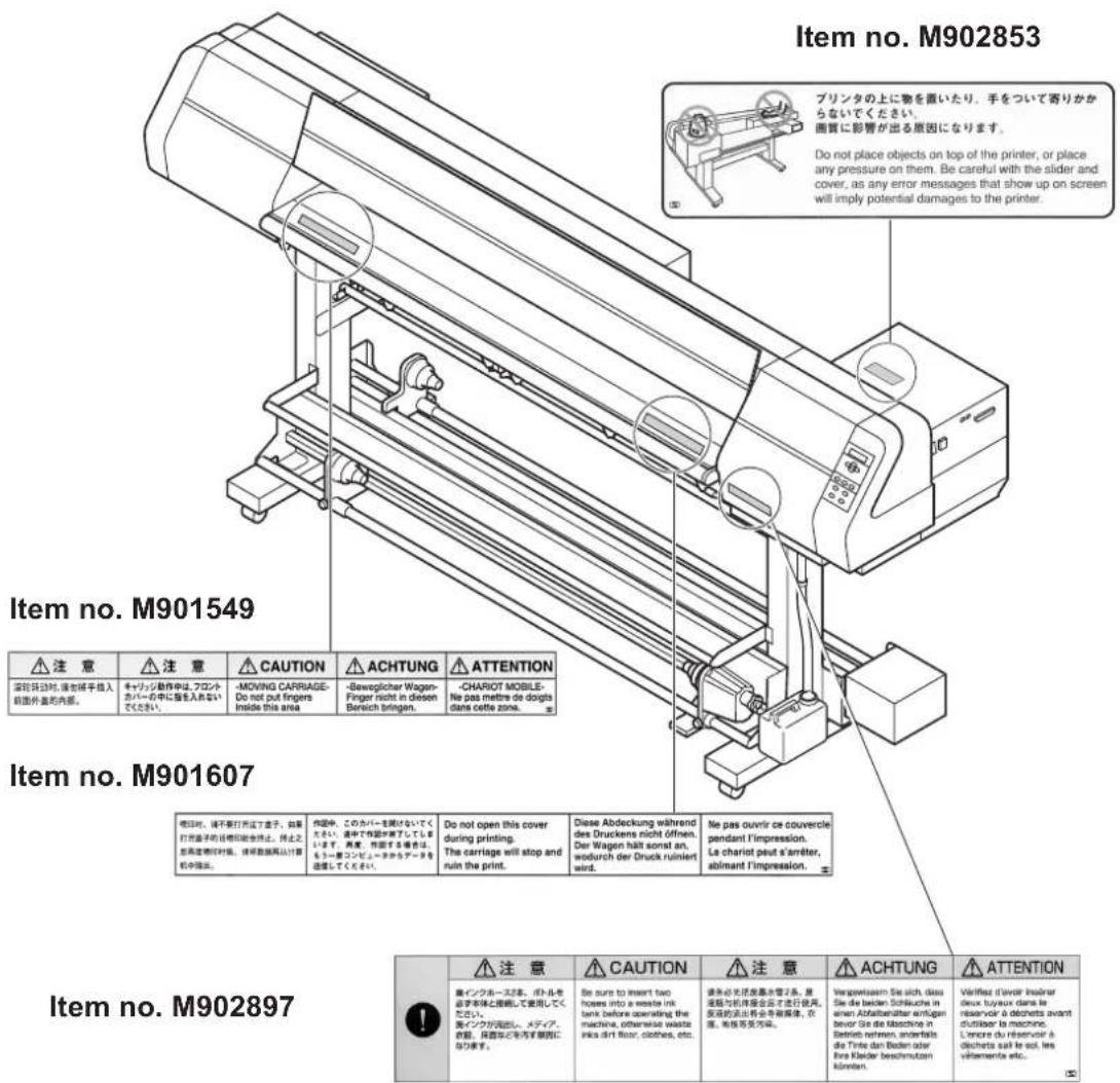
This printer is adhered with a warning label at four locations. Be sure to fully understand the warning given on the labels.
In the case where any of the warning label has become so soiled that the warning message is illegible or has come off, purchase a new one from your local distributor or our office.
Label position
This chapter describes the procedures for unpacking and assembling the printer, and for setting up printer such as setting inks and fabric.
Table of contents
Installation of the printer 1.2
Checking the accessories 1.4
Unpacking and Assembling 1.6
Configuration and Fction 1.13
Names and function of the parts under the front cover 1.15
About other setup 1.20
Connecting the cables 1.24
Switching ON/OFF the power supply.... 1.26
Front cover and maintenance cover 1.28
Ink cartridges 1.29
Fabric for printing 1.34
Before setting the fabric on the printer 1.36
Setting The FabricTo The Printer 1.41
Specifying the scope of printing on the fabric used (Effective printing area) .... 1.49
Origin setting 1.50
Moving the printer 1.51
Installation of the printer
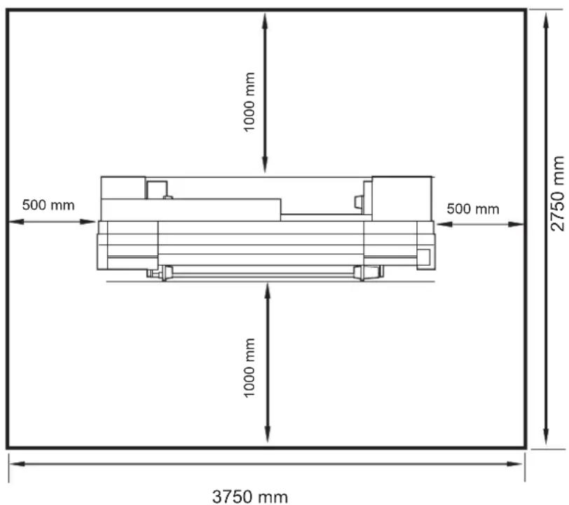
Where to install the printer
Secure a suitable space before using the printer.
The space is required not only for the printer itself but also for printing operation.
| Length Width | Height Gross | weight | ||
| Tx2-1600 27 | 50 mm 750 mm 1 | 350 mm Approx. | 170 kg |
Precautions in installation
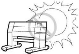
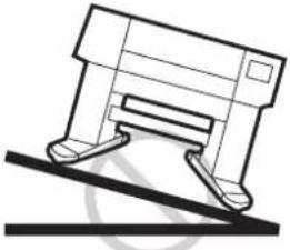
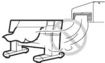
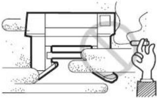
Do not install the printer under the following environment:
| A place exposed to direct sunlight | A plate that is not horizontal |
  |   |
| A place in which temperature and humidity vary by a great margin | A place that vibrates |
| Use the printer under the following environment.Operating environment: 15 to 30°C35 to 65% (Rh) |  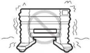 |
| A place exposed to direct air blow from air conditioner, etc. | A place filled with dirt, dust or tobacco smoke |
  |   |
Checking the accessories
Open the packing box and check the components in it.
If you find any missing accessory or damaged one, please contact your local dealer.
NOTE!
- It varies according to your order for Ink Cartridge and the additional accessories.

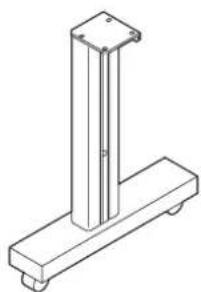
Main unit Take-up device Take-up auxiliary bar
natural_image
Isometric line drawing of a vertical metal frame mounted on a base (no text or symbols)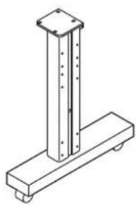
natural_image
Technical line drawing of a mechanical support structure with vertical and horizontal components (no text or symbols)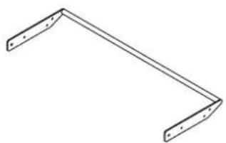
natural_image
Simple line drawing of a V-shaped metal bracket with two flanges (no text or symbols)Left stand Right stand Loading unit auxiliary bar
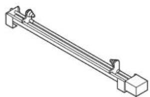
natural_image
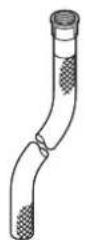
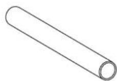
Isometric line drawing of a mechanical lever or support structure (no text or symbols)Waste ink hose Empty fabric core Loading unit
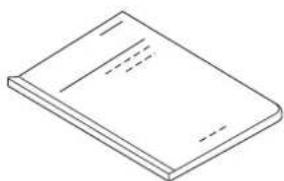
natural_image
Simple line drawing of a closed book with dashed lines indicating text on pages (no visible text or symbols)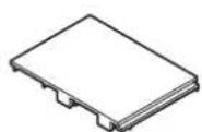
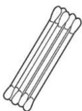
Operation manual (this manual) Platen board x 15 Swab
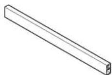
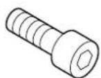
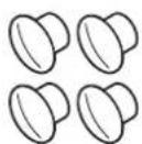
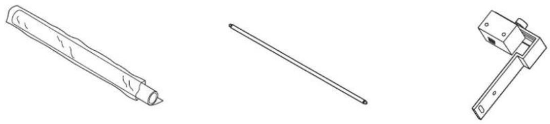
Stand stay M8x60 cap bolt M8x60 Hole plug
for fitting the stand stay (4 pcs) for cover up the screw hole(4pcs)
Printing film
(for adjustment of the device) Slip sheet bar Centering sensor unit
natural_image
Line drawing of a coiled electrical plug with two terminal connectors (no text or symbols)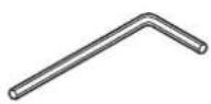
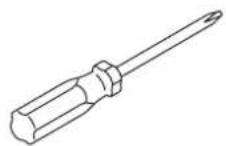
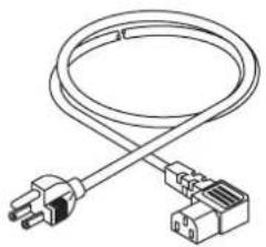
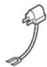
Phillips screwdriver Power cable Hexagonal wrench (L)
natural_image
Isometric view of stacked rectangular blocks (no text or symbols)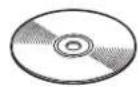
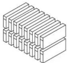
Ink Cartridge (separately sold) 1394 Driver(CD-ROM) Grouding adapter

natural_image
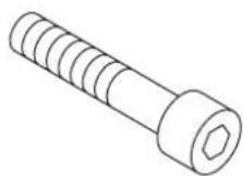
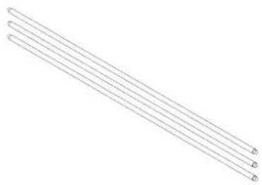
Three parallel diagonal lines with circular endpoints, no text or symbols presentM4 Screw M8 cap bolt Lapel bar x 3
for fitting the take-up device (24 pcs) for fitting the main unit (4 pcs)
Unpacking and Assembling
Assembling the stand and the device

- The package weight is as heavy as approximately 250 kg. Perform the assembly work by at least four persons to ensure safety.
• Exercise added care not to drop the main unit on your feet.
STEP
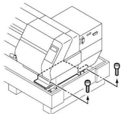
1. Remove the four bolts that fixes the packed pedestals and packed pads.
Take care not to lose these bolts. They are re-used when assembling the stands.
natural_image
Technical line drawing of a mechanical assembly with mounting base and bolts (no text or symbols)Packed pedestals
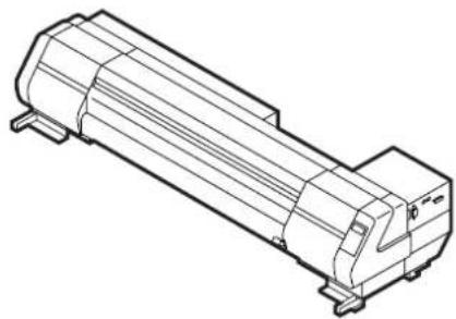
2. Take the main unit together with the packed pedestals out of the package and place them on the floor.
natural_image
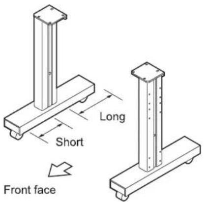
Technical line drawing of a cylindrical mechanical component with mounting flanges (no text or symbols)3. Take the stands out of the package.
Direct the stands so that round tapped holes for the screws are faced outside.
Set up each stand with the side having a groove for fitting the stay coming inside.
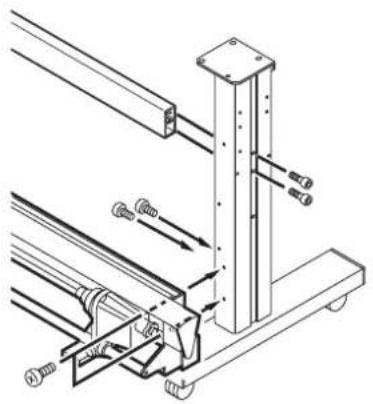
4. Attach the take-up device stand stay to the leg.
Put the take-up device on the leg and then temporarily secure it using the supplied hexagon wrench and screw driver.
5. Lock the stand stoppers.
Lock the stand stoppers so that the stand assemblies will not move.
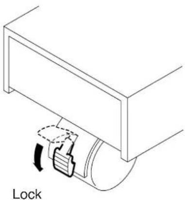
natural_image
Technical line drawing of a mechanical assembly with a lock mechanism (no text or symbols)6. Holding both ends of the main unit with four persons.
Hold up the device at the pedestal support bars.
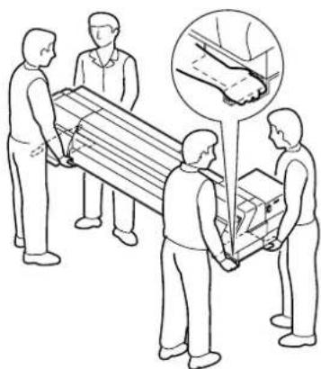
natural_image
Illustration of people handling a large wooden box, with an inset showing hand positioning (no text or symbols)7. Place the main unit on the stands while exercising care not to allow hands to be caught between them.
Set the device on the stand at the position where the screw holes in the device align with the screw holes in the tops of the stands.
Fix to the stands with the screws from under the stands tops.
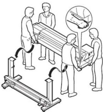
natural_image
Illustration of workers handling a wooden beam and a cart, with an inset showing hand positioning (no text or symbols)
•The device is very heavy. Take care that it does not fall: it is very dangerous.
8. Set the take-up device stand stay in position.
Fasten the screw tightly which was once temporarily attached. Attach the hole plug to cover up the screw.
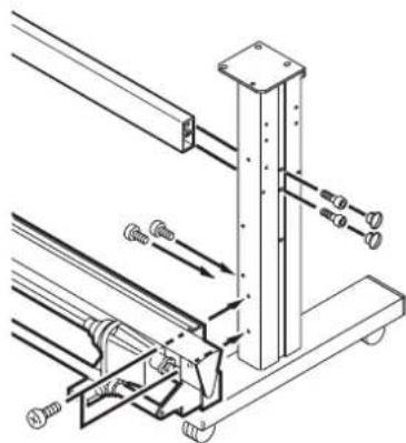
natural_image
Technical line drawing of a mechanical assembly with no visible text or symbols- Connect the cable of take-up device into the connector located at the left bottom of the main unit.
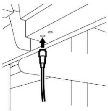
natural_image
Technical line drawing of a pipe connection with a cable and valve (no text or symbols)Attaching take-up auxiliary bar
Align the screw hole of the take-up auxiliary bar with the screw hole on the front face of the stand, then fasten the screws.
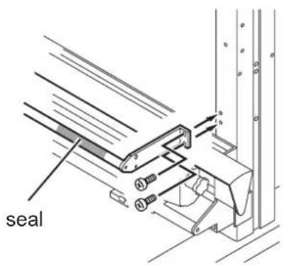
Attaching loading auxiliary bar
Align the screw hole of the take-up auxiliary bar with the screw hole on the front face of the stand, then fasten the screws.
Set a Take-up support bar on the front of the machine with a indication see at the right side of it.
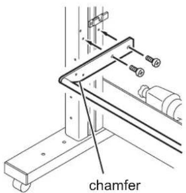
Attaching centering sensor unit
Align the screw hole of the centering sensor unit with the screw hole of the run-out auxiliary bar, then fasten the screws.
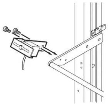
natural_image
Technical line drawing of a mechanical clamp or bracket assembly with no visible text or symbolsAttaching loading unit
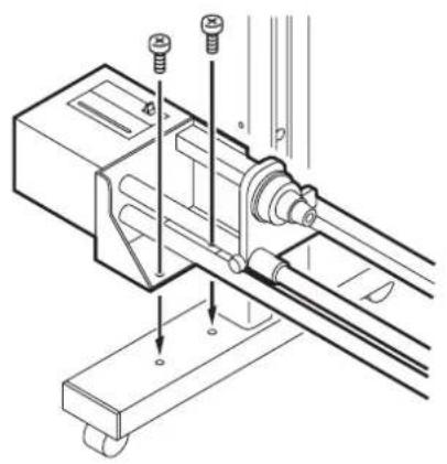
Align the screw hole of the run-out device with the screw hole of the stand, then fasten the screws.
natural_image
Technical line drawing of a mechanical assembly with mounting holes and a shaft (no text or symbols)Connecting connectors and cables
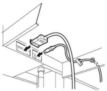
Connect the cable of the run-out device and the cable of the centering sensor unit to the connectors on the rear right of the device unit.
natural_image
Technical line drawing of a cable and connector assembly (no text or symbols)How to remove the stopper
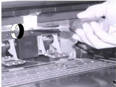
- Loosen a screw fastening the Head Stopper, using Driver.
natural_image
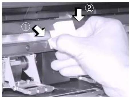
Close-up of a hand using a screwdriver to adjust or install electronic components on a circuit board (no visible text or symbols)- Remove the Head Stopper as shown on the Photo.
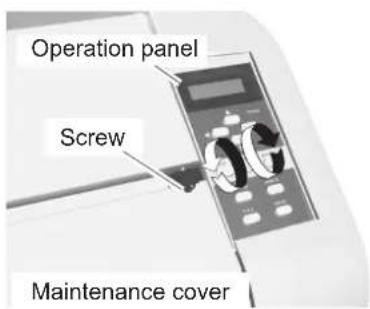
Putting on the maintenance cover
- Put on the maintenance cover.
- Fix the maintenance cover with the screws.
CAUTION
- Do not open the maintenance cover except when it is necessary to clean the station interior. If the maintenance cover is opened during printing operation, the printing data is lost.
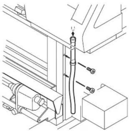
Attach the waste ink hoses.
- Set the waste ink hoses.
- Secure the supplied hose retainer with screws and then attach the waste ink hoses to the device unit.
natural_image
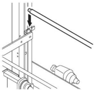
Technical line drawing of a mechanical assembly with pipes and components (no text or symbols)Attaching slip sheet bar
Put the slip sheet on the hanger on the inner side of the stand.
natural_image
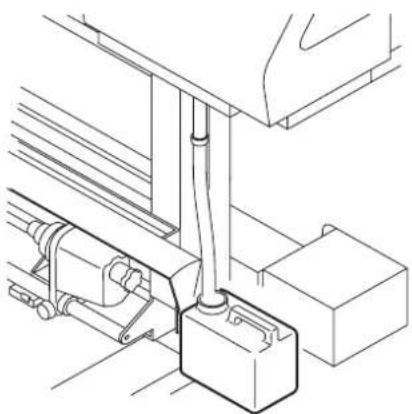
Technical line drawing of a mechanical assembly with a rod and pulley (no text or symbols)Preparing the waste ink tank
Prepare a tank for reserving waste ink.
This printer is not provided with a standard waste ink tank.
Prepare a tank according to your operating situation.
Insert the end of the waste ink hoses attached in the above step to the waste ink tank.
Set them so that there is no ink leakage.
natural_image
Technical line drawing of a mechanical assembly with pipes and blocks (no text or symbols)Configuration and Function
Front face
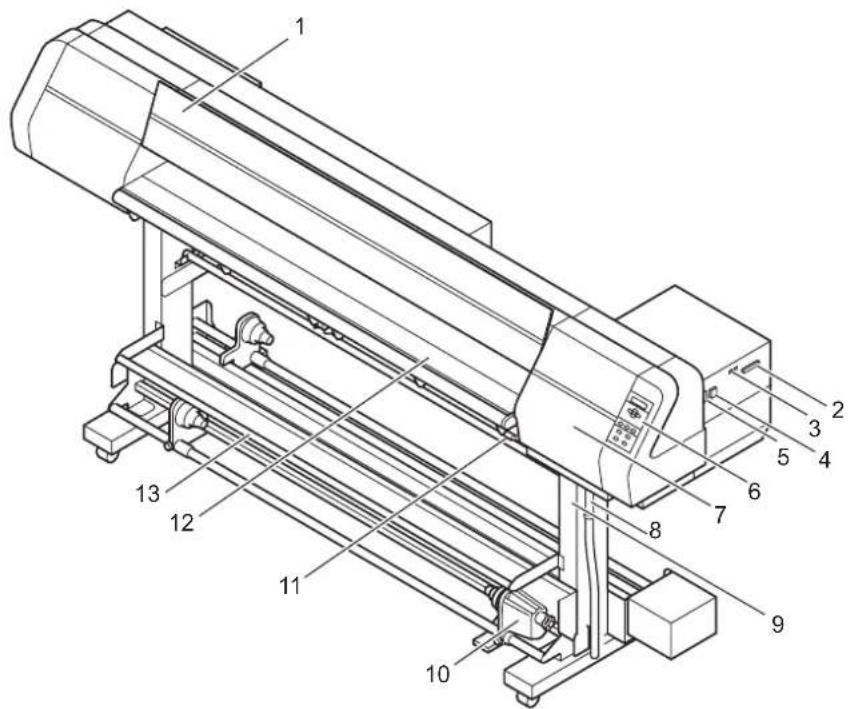
| Name Function | |
| 1. Front cover It is opened when | setting fabric or taking a corrective measure against a fabric jam. |
| 2. Parallel connector Bi-directional | parallel interface connector (complies with IEEE1284) |
| 3. IEEE1394 connector 400Mbps | interface connector compatible with IEEE1394. |
| 4. AC inlet The power cable is connected to the AC inlet. | |
| 5. Power switch It turns on/off the power to the printer. | |
| 6. Operation panel This panel has | the operation keys required for operating the printer and the LCD for displaying set items, etc. |
| 7. Maintenance cover This is the | station cover. During maintenance of the station (See page 4.8), open it by loosening the screws. |
| 8. Waste ink hose Waste ink hose | |
| 9. Stand It supports the main unit. | It is provided with casters that are used to move the printer. |
| 10. Take-up device It supports to | wind up the roll fabric printed, and have the operation named FORWARD / OFF / REVERSE. |
| 11. Clamp lever | It is made to go up-down the pinch roller for holding fabric. |
| 12. Platen | It puts out the fabric as it is printed on. |
| 13. Take-up auxiliary bar | This shaft guides the printed fabric to the take-up printer. |
Rear face
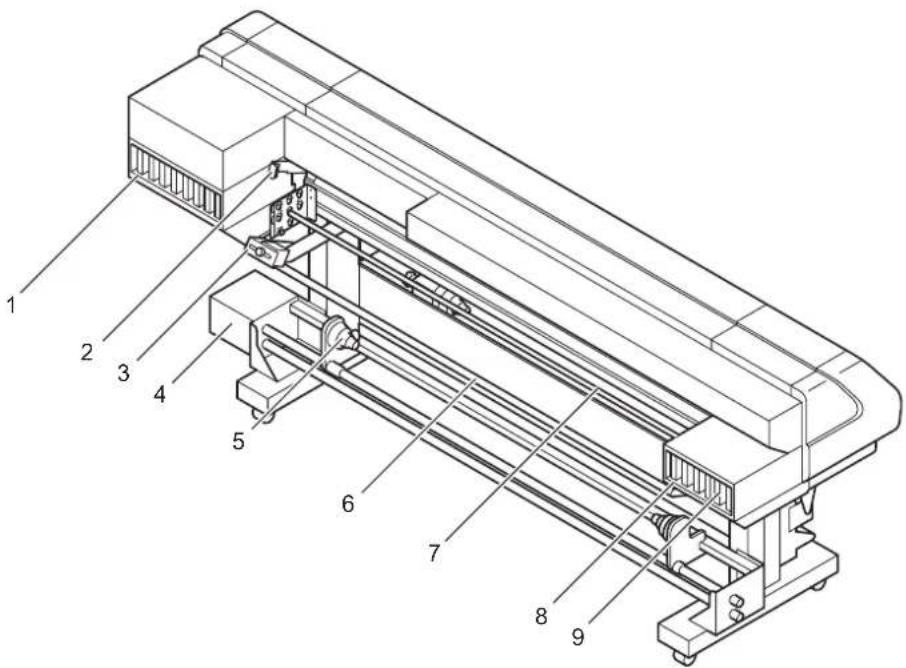
| Name Function | |
| 1. F-row ink station This station houses up to eight ink cartridges. | |
| 2. Clamp lever It is made to go up-down the pinch roller for holding fabric. | |
| 3. Centering sensor unit This sensor detects the fabric edge and optical axis so that the fabric be fed straight. | |
| 4. Loading unit Inserted into both ends of the fabric core to retain the roll fabric. | |
| 5. Roll holder Applicable to roll paper with a thickness of 1.35, 2, or 3 inches. | |
| 6. Loading auxiliary bar This shaft supports the ran-out fabric while it is fed to the platen. | |
| 7. Lapel bar The lapel bar is used to stabilize the medium tension of the run-out side. | |
| 8. R-row ink station This station houses up to eight ink cartridges. | |
| 9. Ink cartridge Each cartridge contains ink of a specific color. | |
Names and function of the parts under the front cover
Under the front cover, there are the carriage, capping station, etc. necessary for printing operation. The mechanisms provided under the front cover are explained below.
Carriage
The carriage is provided with print heads for printing, etc. It is also provided with a head height adjustment screw for adjusting the head height according to the thickness of the fabric used. The carriage moves during printing, and fabric detection.
When cleaning the capping station, execute the STATION MAINTENANCE function to move the carriage. (See page 4.8 "Moving the carriage for cleaning the station interior [Carriage Out].")
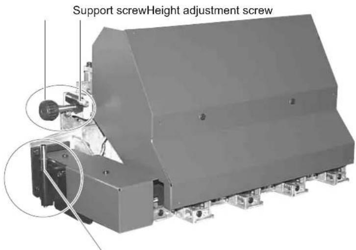
Head height adjustment rod
CAUTION • Starting the printing operation without adjusting the carriage height can cause damage not only to the fabric but also to the printer itself.
NOTE! • When setting a fabric in position for printing, be sure to adjust the head height.(See page 1.36)
Capping station
The capping station consists of ink caps, wipers for cleaning the heads, etc.
Ink Cap : It covers the nozzles of print head to prevent from drying up.
Wiper : It is used to clean the head nozzles.
NOTE!
- Clean the capping station frequently to keep the capping station clean. If the wiper fluffs, replace it immediately.
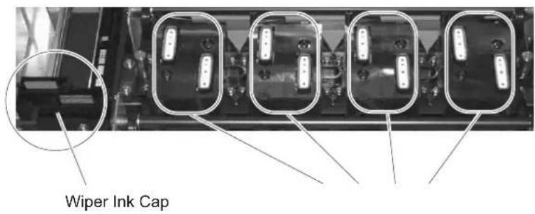
The pinch roller and feed roller
This printer retains a fabric with the pinch roller and the feed roller.
During printing operation, the feed roller feeds the fabric forward.
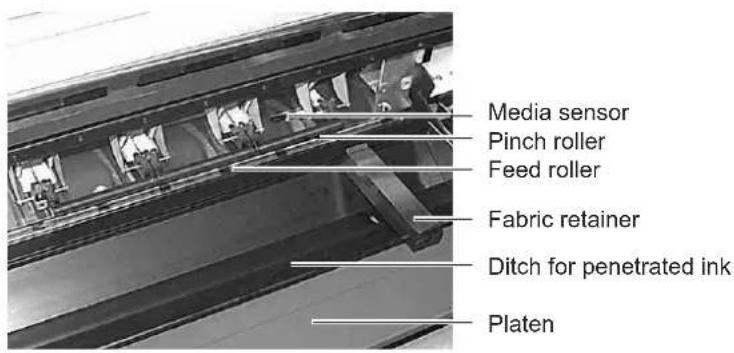
NOTE!
- While the printer is not being used, keep the pinch roller in the raised position. If the pinch roller is left lowered for an extended period of time, it can deform and fail to securely retain the fabric.
The media sensor
The media sensors detects the presence of the fabric and the end of fabric.
There is one media sensors on the platen.
Set up fabric to cover media sensor at the back side of platen absolutely.
If the part of fabric is not on fabric, the fabric can not be detected.
NOTE!
- If a transparent fabric or a fabric whose reverse side is colored in black, the sheet sensors may fail to detect the sheet. In this case LCD gives the following message.
ERROR 50 MEDIA SENSE
Head hight adjustment rod and adjustment screw
When a fabric is set for the first time or replacing a fabric in different thickness, it is necessary to adjust the height of the head.
CAUTION
- If the printer is operated without adjusting the head height, the head may get caught on the fabric, causing damage to the heads.

- For the method of head height adjustment, see Adjusting the Head Height [HEAD HEIGHT] (page 1.36) in this chapter.
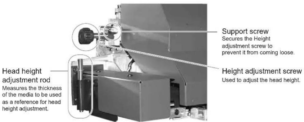
Fabic retainer
If the edge of the fabric is curled or it is raised, it may be caught by the head or inferior ink discharge may occur.
To avoid this trouble, use the fabric retainer.

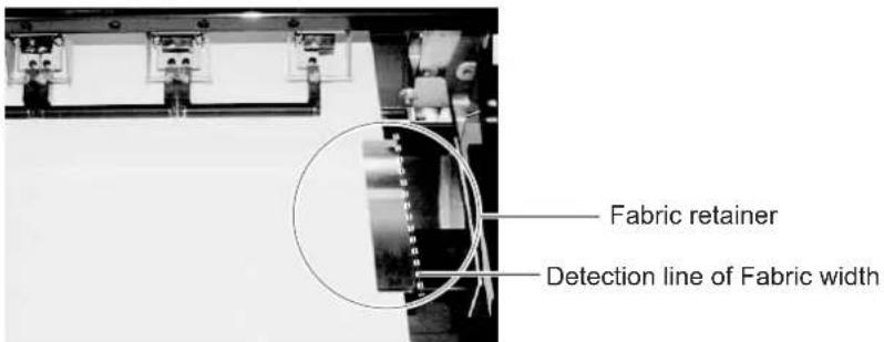
- The fabic retainer also act as a detection board which detects the printing width. Printing with the full width (up to 1620mm width) is possible by setting the fabic ratainer to a position apart from the edge.
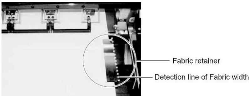

- If a fabic retainer is stained by ink, it can be removed for washing. Remove it from the end of notch in both side.
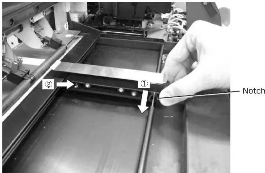
NOTE!
- When using fabric retainer, be sure to adjust the head height to 3mm or more.
When raising height of the fabric retainer, be sure to adjust the head height according to the height of it.
Using them with a low head height may cause failure.
Ditch for penetrated ink and platen boards
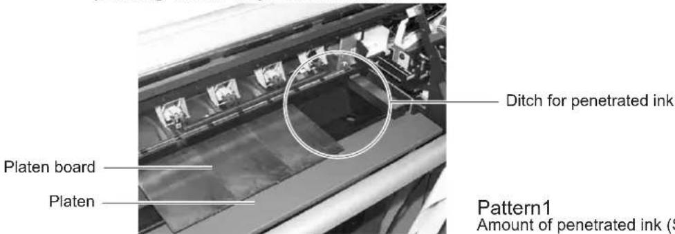
Printing on a coarse-textured fabric may cause ink to penetrate the fabric.
If the fabric runs out in this condition, it may be stained by the ink on the platen.
The ditch for penetrated ink is provided to avoid this trouble.
NOTE!
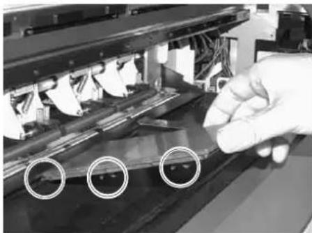
- For printing to a fabric without ink penetration, attach the platen boards so that the ditch for penetrated ink be covered by them.
natural_image
Close-up of a gloved hand operating a mechanical device with three circular features on its surface (no visible text or symbols)
- Set the projection on the back of the platen board to the projection at the edge of the ditch for penetrated ink.
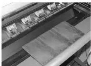
- The width of the ditch for penetrated ink can be changed in three steps depending on the way of attachment.
natural_image
Industrial conveyor belt system with multiple rollers and a roller, no visible text or symbols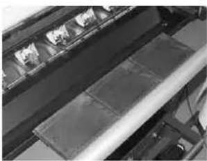
natural_image
Close-up of a mechanical conveyor belt system with metal sheets (no visible text or symbols)Amount of penetrated ink (Middle) Amount of penetrated ink (Large)
Pattern2 Pattern3

- For attachment of the platen boards, refer to page 1.22.
NOTE!
- If the platen board is not used, remove all the platen boards from the platen. If you place a platen board outside the fabric retainer, not the position of the fabric retainer but the position of the platen board is detected at the time of fabric detection.
About other setup
Attaching lapel bar
The lapel bar is used to stabilize the media tension of the run-out side.
If the media tension of the roll-out side becomes unstable, printing is adversely affected (vertical black or white lines occurs).
If the tension is too high, the media becomes susceptible to vertical wrinkles which may cause black or white lines. If the tension is too low, wrinkles occurring at the rear portion of the pinch roller and passing it make the gap between the media and head uneven, adversely affecting printing.
Therefore, it is necessary to change the mount position of the lapel bar and perform printing at an appropriate lapel position. Even with the same cloth type, media characteristics change depending on the pre-treatment and the presence or absence of the gumming processing at both ends of the cloth. Be sure to perform test printing to measure an appropriate lapel position.
NOTE!
- Be sure to perform test printing, check the printing result, then determine whether the lapel bar can be used or not.
- The characteristics of material of medium may be changed by pre-treatment. If the pre-treatment is changed, be sure to perform test printing.
- Please reset the lapel bar properly if it's shaky up and down.
- Please adjust the attachment of the side plate assembly if the lapel bar does not rotates smoothly.
STEPS:
-
Loosen the thumb-screw inside the left and right plates.
-
Hold the loosened thumb-screw.
Push and move the slide plate toward the printer unit it hit the stopper.
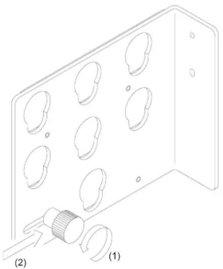
natural_image
Technical line drawing of a metal plate with multiple circular holes and a threaded component, labeled (1) and (2), showing no text or symbols.- Insert the lapel bar into the hole of the side plate and then allow it to slip in the lower slot.
- Make sure that the bearing is put into the side plate and that the lapel bar is set to the position where it rotates easily.
- Holding the left and right thumb-screws, pull out the slide plate toward the rear side of the printer and then turn the thumb-screws to secure them.
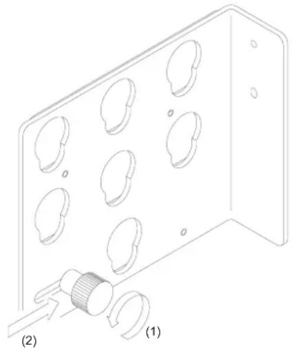
natural_image
Technical line drawing of a mechanical component with circular holes and a threaded fitting (no text or symbols)Attaching the platen boards
Attach the platen boards when using a fabric without ink penetration.
Set the attachment position and orientation of the platen boards in three steps according to the degree of ink penetration. (See page 1.14)
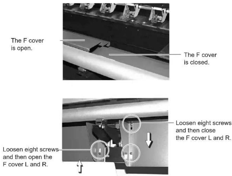
Changing gap for fabic retainers

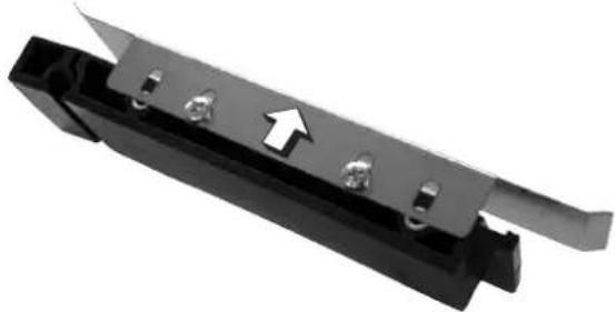
- When the thickness of the fabric used is 0 to 4mm , use it with the stainless plate adjusted by moving the outside long hole hole and then secured with a screw.
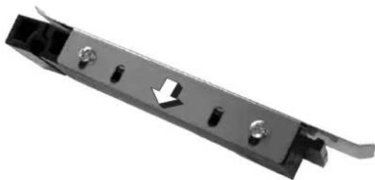
natural_image
Metal mechanical component with bolt holes and a white arrow indicating direction (no text or symbols)
- When the thickness of the fabric used is 3 to 7mm , use it with the stainless plate adjusted by moving the inside long hole hole and then secured with a screw.
natural_image
Close-up of a black metal tool holder with a white arrow pointing to its side (no text or symbols visible)NOTE!
- When raising the stainless plate, be sure to adjust the head height. Failure to do so may cause damage to the head.
• Factory default setting is 1mm.
Installing IEEE1394 output driver
When connecting the printer using the host computer and IEEE1394 interface, it may be necessary to install the IEEE1394 output driver and RasterLink Pro (RIP).
NOTE!
- For the installation procedure, refer to the contents of the CD-ROM supplied with the printer.
- RasterLink Pro is optional accessory.
Connecting the cables
Connecting the interface cable
Connect the printer to the computer with the appropriate interface cable.
Two types of interface cables are available. Select the interface cable appropriate to the computer and output software.
NOTE!
- T urn off the power switch of the printer (the switch has to be tilted toward the "O" side) in prior to the connection of the interface cable and the power cable.
For Windows 2000, XP (IEEE1394)
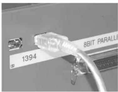
When the computer is operated in Windows 2000 or XP with IEEE1394 interface, use an IEEE1394 interface cable to connect the computer and the printer together.
It is possible to use an IEEE1284 interface cable for connection between the computer and the printer. In this case, however, the data transmission speed decreases.
NOTE!
• The application used must be applicable to IEEE 1394.
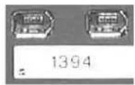
- Either of the two IEEE1394 connectors can be used.
Configuration of connector (IEEE1394)
For other operating system (IEEE1284)
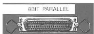
When operating system is other than Windows 2000 or XP, use an IEEE1284 interface cable to connect the computer and the printer.
Configuration of connector (IEEE1284)
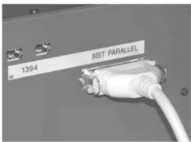
NOTE!
- If the customer uses Windows 2000 or XP and the computer is not provided with an IEEE1394 board, contact your nearest RIP provider or MIMAKI sales office.
Connecting the power cable
Connect the power cable to the receptacle of the following specifications.
• Voltage : AC 100 - 240 V ±10%
• Frequency : 50/60 Hz ±1%
• Capacity : 5 A or more (500 W or more)


- Be sure to turn off the power switch of the printer in prior to the connection of the power cable.
- Be sure to insert the power cable into an appropriately-grounded receptacle. If not, there is a fear of arising electric shock hazards and damage to the printer.
STEPS:
- Connect the power cable to the AC inlet.
Configuration of power cable
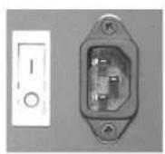
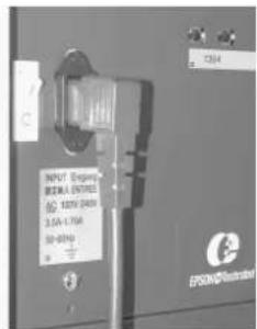
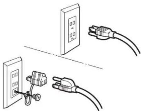
- Connect the power cable to the 3-pole receptacle.

For a 2-pole receptacle, connect the grounding adapter supplied with the printer to the power cable plug. Properly ground the green wire (ground lead) of the grounding adapter.
natural_image
Illustration of three electrical connectors: a wall-mounted switch, a plug-in socket connected to a power outlet, and a separate plug with wires (no text or symbols)Switching ON/OFF the power supply
After setting up the printer, switch on and off the power as described below.
Turning the power on
STEPS:
- Turn on the power to the computer, etc. that are connected to the device.
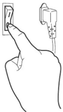
- Turn on the power to the printer.
Tilt the power switch toward the "I" side, and the power to the printer is turned on.
NOTE!
- At this time, the front cover must be closed. With the front cover kept open, the carriage does not move even when the power is switched on.
When the power is switched on, the LCD first displays [BOOT] and then displays the firmware version number.
The message "PLEASE WAIT" appears flashing on the LCD.
natural_image
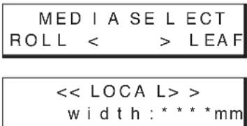
Line drawing of a hand inserting a wall-mounted electrical socket into a socket (no text or symbols)- If a fabric has been set on the printer, the prompt [MEDIA SELECT] is displayed on the LCD when the power is switched on. After selecting media, the printer detects the media and returns to the LOCAL mode.
Turning the power off
To turn the power off, check first whether or not there is data received and there remains data that has not yet been output.
Also be sure that the head rests at the capping station.
NOTE!
- If the power is turned off while the printer is engaged in printing, the head may fail to be retracted in the capping station. If the head is left without capped for an extended period of time, the nozzle will be clogged with dust. If the power to the printer is turned off without the head capped, re-turn on the power to the printer.
STEPS:
- Turn off the power to the computer, etc. that are connected to the printer.
- Turn off the power to the printer.
Tilt the power switch to the "O" side.
natural_image
Line drawing of a hand pointing at an electrical outlet with a secondary plug (no text or symbols)Front cover and maintenance cover
Opening/closing the cover
Do not open the front cover and the maintenance cover while the printer is in operation. If you open the front cover or the maintenance cover during printing, the carriage will stop for safety, reselting in abortion of printing. In this case, re-start the printer and computer following the procedure described below.
Keep the front cover and maintenance cover closed regardless during printing operation or not. Otherwise it cause the dust attach to the head nozzle.
Do not open the maintenance cover except when it is necessary to clean the station interior.
When opening the cover during printing
If you open the front cover or the maintenance cover during printing, operate the following steps:
STEPS:
- When opening the cover during printing, the message shown on the right will be displayed.
Close The Cover
- After the completion of data transmission from the computer, close the cover, then press the [ENTER] key.
ENTER

PRESS

- If the data transmission from the computer cannot be stopped, first switch off the power supply of the computer then switch it on to restart the computer.
The carriage will start to move.
The carriage will carry out as same as after turning on the power of printer.
Ink cartridges
Types of ink
3 types of ink are available for this printer at the moment. The characteristics of each ink type are described below.
Acid dye ink [Acid] : Suitable for wool, silk, and other animal fibers and nylon.
Available ink colors include black, cyan, magenta, yellow, light cyan, light magenta, gray, blue and red.
Disperse dye ink [Disp] : Suitable for polyester, acrylic, etc.
Available ink colors include black, cyan, magenta, yellow, light cyan, light magenta, gray, blue and light blue.
Reactive dye ink [Reac] : Suitable for wool, silk in addition to cotton, rayon, etc.
Available ink colors include black, cyan, magenta, yellow, light cyan, light magenta, gray, blue, orange, red and golden yellow.
Precautions in handling the ink cartridge
CAUTION
- U se Mimaki-recommended ink. Using third-party ink or ink cartridges may cause a trouble.
The user shall be charged for a repair to correct any damage resulting from these inks or ink cartridges even if under warranty period.
- Never refill the ink cartridge with ink. This might cause a trouble. Mimaki assumes no responsibility for any damage caused by using replenished ink cartridges.
- Do not touch or stain the contact of the cartridge PCB, as this may cause failure of the PCB.
NOTE!
- The ink is not toxic. However, avoid direct contact with the ink. If ink contacts the skin or fabric, immediately wash it off with detergent or water. In the event that ink gets in eyes, immediately rinse it off with a plenty of running water and consult a medical doctor.
- Be sure to store the ink cartridges in a cold and dark place. Do not store the cartridge in too high/low temperature or high humidity condition. If the ink cartridge is moved from a cold place to a warm place, leave it in the room temperature for three hours or more before using.
- Open the ink cartridge just before installing it in the printer. If it is opened and left for an extended period of time, normal printing performance may not be ensured.
- Make sure to thoroughly consume the ink in the ink cartridge, once it is opened, within six months. If an extended period of time has passed after opening the cartridge tank, printing quality would be poor.
- Dispose empty ink cartridges and waste ink in accordance with national and local ordinances effective in your area.
- D o not use expired ink cartridges. The expiration date is printed on the ink cartridge.
- Do not shake the ink cartridge violently. Shaking or turning it roughly can cause leakage of ink.
Ink stations
As viewed from the front of the printer, the ink station on the right side is called the "F-row ink station" and the ink station on the left side is called the "R-row ink station."
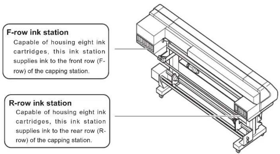
* The figure shows the unit when viewed from rear side.
NOTE!
- In each ink station, set eight ink cartridges containing ink of the same type. The setting position of each color ink cartridge differs according to the ink type. Before setting a new ink cartridge of different ink type or color, be sure to wash the ink line and print head. (See to page 4-26)
Relationships between ink station and head row
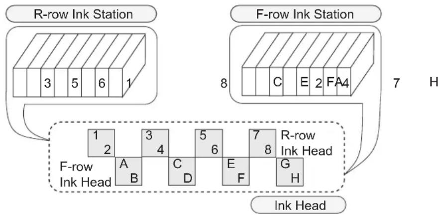
The right ink station supplies ink to the front row (F-row) of heads.
The left ink station supplies ink to the rear row (R-row) of heads.
Remember these relationships when checking the heads for clogged nozzles and replenishing inks.
flowchart
graph TD
    A["R-row Ink Station"] --> B["3 5 6 1"]
    C["F-row Ink Station"] --> D["8 C E 2 FA4"]
    D --> E["7 H"]
    E --> F["R-row Ink Head"]
    F --> G["1 2 3 4 5 6 7 8"]
    G --> H["F-row Ink Head"]
    H --> I["A B C D E F G H"]
    I --> J["Ink Head"]
B D
Display of ink type
Ink type is displayed when an ink cartridge is newly set, an ink cartridge of different type is set, or a type of ink is selected from the ones that have already been set.
The information displayed on the LCD consists of the row of ink station (R or F row) and the type of ink.
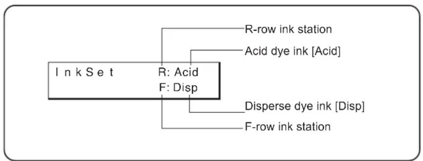
flowchart
graph TD
    A["I n k S e t"] --> B["R: Acid"]
    A --> C["F: Disp"]
    B --> D["R-row ink station"]
    B --> E["Acid dye ink [Acid"]]
    C --> F["Disperse dye ink [Disp"]]
    C --> G["F-row ink station"]
Setting ink cartridges
Setting for 1-way high-speed printing
New piezo electric heads, the staggered-layout print head provides more attractive, faster printing, and allows ultra high-precisions 8-head 1-way printing. Set the left and right ink cartridge cases with ink cartridges of the same types and same colors.
R-row ink station F-row ink station
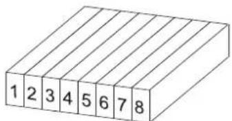
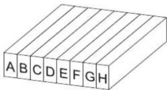
NOTE!
- S et ink cartridges of the same type and same color to 1 and A, 2 and B, 3 and C, 4 and D, 5 and E, 6 and F, 7 and G, and 8 and H, respectively.

- During initial ink setting or ink change, register the appropriate ink type for each ink station (See page 4.26). The registered ink type is necessary when checking the printing information and changing the heads used.
- When two sets of ink of the same type are set in the two ink stations, it is possible to use the function which, if the ink in the ink station currently used runs out during printing, switches from that ink station to the other ink station to permit the printing operation to be continued without interruption (See page 3.24).
Setting for 2-way multi printing
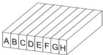
Alternatively, using two sets of three heads in 2-way printing mode, each with different inks, gives you the functionality of two 8-color printers in a single unit. Set the left and right ink cartridge cases with ink cartridges of different types and colors. Set ink cartridges of different types and colors to 1 through 8 and A through H.
R-row ink station
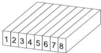
F-row ink station
NOTE!
- Set ink cartridges of different types and colors to 1 through 8 and A through H.

- During initial ink setting or ink change, register the appropriate ink type for each ink station (See page 1.32).
- It is necessary to register ink type to the printer for checking the printing information and switching the head set.
Set the ink cartridge referencing the following table.
| NO. | Acid dye ink Disperse dye ink (For direct print and transfer) (For transfer) | ||
| 1 | GRAY (SPC-0355GR) | GRAY (SPC-0356GR) | |
| 2 | BLACK (SPC-0355K) | BLACK (SPC-0356K) | BLACK (SPC-0357K) |
| 3 | CYAN (SPC-0355C) | CYAN (SPC-0356C) | CYAN (SPC-0357C) |
| 4 | LIGHT CYAN (SPC-0355LC) | LIGHT CYAN (SPC-0356LC) | LIGHT CYAN (SPC-0357LC) |
| 5 | MAGENTA (SPC-0355M) | MAGENTA (SPC-0356M) | MAGENTA (SPC-0357M) |
| 6 | LIGHT MAGENTA (SPC-0355LM) | LIGHT MAGENTA (SPC-0356LM) | LIGHT MAGENTA (SPC-0357LM) |
| 7 | YELLOW (SPC-0355Y) | YELLOW (SPC-0356Y) | YELLOW (SPC-0357Y) |
| 8 | BLUE (SPC-0355BL) or RED (SPC-0355R) | BLUE (SPC-0356BL) | ORANGE (SPC-0357OR) or RED (SPC-0357R) or GOLDEN YELLOW (SPC-0357GY) |
| A | GRAY (SPC-0355GR) | GRAY (SPC-0356GR) | GRAY (SPC-0357GR) |
| B | BLACK (SPC-0355K) | BLACK (SPC-0356K) | BLACK (SPC-0357K) |
| C | CYAN (SPC-0355C) | CYAN (SPC-0356C) | CYAN (SPC-0357C) |
| D | LIGHT CYAN (SPC-0355LC) | LIGHT CYAN (SPC-0356LC) | LIGHT CYAN (SPC-0357LC) |
| E | MAGENTA (SPC-0355M) | MAGENTA (SPC-0356M) | MAGENTA (SPC-0357M) |
| F | LIGHT MAGENTA (SPC-0355LM) | LIGHT MAGENTA (SPC-0356LM) | LIGHT MAGENTA (SPC-0357LM) |
| G | YELLOW (SPC-0355Y) | YELLOW (SPC-0356Y) | YELLOW (SPC-0357Y) |
| H | BLUE (SPC-0355BL) or RED (SPC-0355R) | BLUE (SPC-0356BL) | ORANGE (SPC-0357OR) or RED (SPC-0357R) or GOLDEN YELLOW (SPC-0357GY) |
Fabric for printing
This section describes the types of fabric that can be used with the printer and the method of setting the media used.
Types of fabic that can be used
The types of fabric that can be used with this printer "Roll" and "Leaf" fabric are cut sheet media. However, because leaf fabric is handled in the same manner as roll fabric, be careful about the setting position of leaf fabric.
CAUTION
- When using the Leaf, the following functions are disabled.
[CENTERING]
[TAKE-UP]
Sizes of fabric that can be used
| fabric | Maximum 1650 mm | |
| Minimum 200 mm | ||
| printing width 1620 mm | ||
| Thickness 7.0 mmmm or less | ||
| Roll outside diameter ∅ | 180 mm or less | |
| Roll weight 15 Kg or less | ||
| Roll inside diameter 3, 2, and 1.35 inches | ||
| Printing surface Faces OUT | ||
| Roll end treatment Light | -adhesive tape is used to allow the paper to be removed from the core with ease. | |
Precautions in handling the fabric
Carefully observe the following when handling the fabric.
CAUTION
NOTE!
- Use pre-processed fabrics recommended by MIMAKI.
- When setting the fabric used, be sure to adjust the head height. Otherwise, the fabric and/or the head can be damaged.
- Store fabric in a bag. Wiping off dust, waste paper and flocks accumulated on a fabric will adversely affect the fabric due to static electricity.
- Do not use ink-adhered fabric with high elasticity.
Use of such a fabrics may cause contact with the print head nozzle, displaced printing, or other trouble.
- Do not use fabric with curled edges.
Use of such a fabric may cause contact with the print head nozzle, resulting in inferior ink discharge. If fabric that is likely tightly curl, flatten first the fabric before using it for printing. Heavily-curved fabric affect the printed picture quality.
- Do not use fabrics with extremely coarse fixture.
The printer may not detect the fabric properly.
Limited media
With the following media, correction from the printer is difficult.
When using any of the following media, perform test printing to determine whether it can be used or not.
NOTE!
- When using a media other then the following, be sure to perform test printing to confirm the print result and then determine whether it can be used or not.
- Hight stretch fabric (Stretch materials, vertically extendable knit, etc.)
- Materials which become largely extendable when getting wet by printing.
- Materials with large width variations.
- Materials which present partial wrinkles of slacks when being spread on a flat surface or materials which are totally curved.
- M materials with large take-up shift at the ends of media when rolled.
- Roll media with a paper tube whose strength is insufficient and which bends when attached to a feeding unit.
Before setting the fabric on the printer
Before setting the fabric, be sure to confirm the Ditch for penetrated ink. If ink is there, wipe them with a waste cloth. (see more details 2.14)
Adjusting the head height according to the fabic [HEAD HEIGHT]
It is necessary to adjust the head height according to the thickness of the fabric.
If the height of the head is inappropriate to the thickness of the fabric, the printer cannot work properly.
More important, operating without adjusting the head height is very dangerous: it can damage the fabric and the printer.
When a new fabric different in thickness from the current fabric is to be used, be sure to make proper adjustment of the head height. [HEAD HEIGHT] is a function to set the distance between the fabric surface and head to 3mm.
NOTE!
- Adjust the head height before setting the fabric on the printer.
If an attempt is made to adjust the head height with the fabric kept set on the platen, the fabric gets caught on the carriage during “carriage out” operation, causing damage to the head.
- If you set the head height to 1.2mm (minimum value) from the platen surface, note the following points:
- Remove the fabric pressers. If they are used, the head knocks up against the fabric retainers, which may cause damage to the printer.
- Use fabrics without wrinkle or uneven surface. If a fabric with wrinkle or uneven surface is used, the head may rub or catch the fabric to push it to a position resulting in fabric jam.
- Except for cases when using film or other flat thin fabric, set the head height to 3mm.
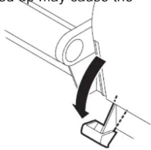
- Before performing [CARRIAGEout], be sure to move down the clamp lever on the front side of this printer.
Performing [CARRIAGEout] with the clamp lever moved up may cause the
head to hit the pinch roller damaging them.
natural_image
Mechanical assembly diagram showing a lever mechanism with a curved arrow indicating motion (no text or symbols)STEPS:
- Move down the clamp lever on the front face on the printer.
Media
No Media
- Press the [FUNCTION] key.
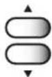
- Press the JOG keys[ ▲] and [▼ to select [MAIN-TENANCE].
- Press the [ENTER] key.
- Press the JOG keys[ ▲] and [▼ to select [HEAD HEIGHT].
- Press the [ENTER] key.

- If the fabric is loaded, "REMOVE MEDIA" will be displayed. In this case, remove the fabric.
- Press the [ENTER] key.
The carriage will come out of the capping station.
- Open the front cover and then set the fabric to be used on the platen.
- Move the carriage to a position where adjustment is easy.
The carriage can be moved manually.
-
Adjust the head height.
-
Loosen the support screw (1), turn the height adjustment screw (2) in the direction shown, and move the head upward.

FUNCTION
SETUP
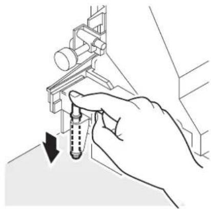
- Push down the head height adjustment rod by the right hand.
Push down the head height adjustment rod till it stops moving anymore.

- If the tip of the head height adjustment rod makes contact with the surface of the fabric, repeat step 10.-1 shown on the preceding page to raise the head.
- Turn the head height adjustment screw in the direction shown and move the head downward.
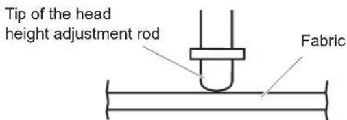
With the head height adjustment rod kept pushed, lower the head till the tip of the rod makes contact with the surface of the fabric.
- Retighten the support screw after completing the head height adjustment.
natural_image
Hand inserting a screw into a mechanical component (no text or symbols visible)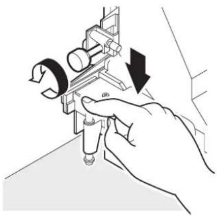
natural_image
Illustration of a hand using a mechanical tool to adjust a component, with no visible text or symbols.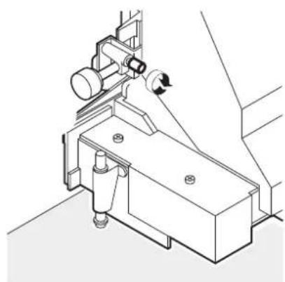
natural_image
Technical line drawing of a mechanical assembly with no visible text or symbols- Close the front cover.
HEAD HEIGHT COMPLETED : en t
10. Press the [ENTER] key.
The carriage will come back to the capping station.
The LCD shown on the right is displayed.
![Mimaki Tx2-1600 - Press the [ENTER] key. - 1](/content/2026/05/919850/images/077cdc489ea8be3901a71bb2fa7c4cd46132fc63419b00cb4c964eaa21b6530c.jpg)
INITIALIZING PLEASE WAIT
Media No Media
Points in head height adjustment

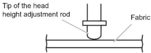
- When the head height is so adjusted that the tip of the head height adjustment rod just makes contact with the surface of the fabric, the distance between the head and the printing surface of the fabric becomes optimum.
- A s long as the head height is so adjusted that the tip of the head height adjustment rod just makes contact with the surface of the fabric, the distance between the head and the printing surface of the fabric remains unchanged even when the head is raised.
- To avoid fluffing of the fabric surface, warp of the fabric edge, or waving of the fabric during printing, the distance between the head and the printing surface of the fabric can be increased.
- When the distance between the head and the printing surface of the fabric is increased, the print quality deteriorates.
Optimum distance
Distance increased
When a fabric having fluffy surface, warp, or irregular surface is used
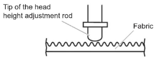

- When the head height is adjusted, the printing points shift in position. After head height adjustment, be sure to correct the dot positions. (See page 4.6)
Setting the mating sheet
The mating sheet is used to prevent ink penetration of the fabric which is not dried after printing.
- Set the fabric core of the slip sheet to the slip sheet bar hanger.
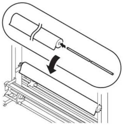
natural_image
Diagram of a mechanical device with rollers and a rod, showing motion direction (no text or symbols)Adjusting parallelism of loading unit
If the parallelism of the loading unit is remarkably broken, the fabric deviation or wrinkle may occur. In this case, adjust the parallelism of the loading unit.
-
Fasten the screw which secure the loading unit to the printer.
-
Adjust the position of the loading unit on the side of fabric deviation or wrinkle occurrence so that it be apart from the printer, then secure it with a screw.
-
Clamp the fabric again and then start printing.
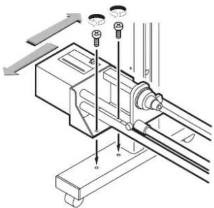
natural_image
Technical diagram of a mechanical assembly with mounting holes and a shaft (no text or labels)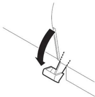
natural_image
Diagram of a mechanical lever mechanism with a curved arrow indicating motion (no text or symbols)NOTE!
- Note that fabric deviation may occur if the width is adjusted too large.
Setting The FabricTo The Printer
The fabric that can be used are roll and leaf fabric.
Leaf fabric is handled in the same manner as roll fabric for printing.
When using leaf paper for setup list printing, for example, be careful about the setting position.
Setting a roll fabic
The procedure for setting roll fabric is described below.
NOTE!
• The roll is heavy in weight. Take care not to drop it on your foot.
- When setting the fabric, be sure to check that the head height has been properly adjusted.
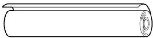
natural_image
Simple line drawing of a cylindrical object with a circular hole on top (no text or symbols)STEP
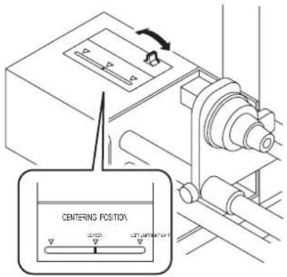
1. Center the centering indicator.
Push the switch to the left and right so that the red indicator be positioned around at the center of the slit.
(See page 1.45)
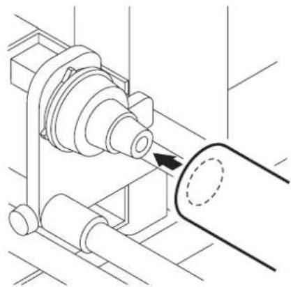
2. Insert the let-hand roll holder into the core of the roll fabric.
Push roll fabric onto the roll holder till the roll core no longer moves.
The inside diameter of the roll fabric core may be 1.35 inches, 2 inches and 3 inches.
Fit the roll fabric to the roll holder appropriate to the core inside diameter.
natural_image
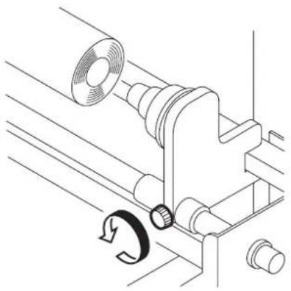
Technical line drawing of a mechanical assembly with a cylindrical component and a curved pipe (no text or symbols)3. Loosen the screw of the right-hand roll holder.
Adjust the roll holder position to the width of the roll fabric.
natural_image
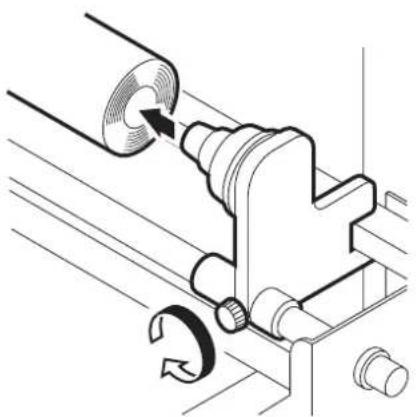
Technical line drawing of a mechanical assembly with no visible text or symbols4. Insert the right-hand roll holder into the core of the roll fabric.
When the roll holder have been inserted all the way into the fabric core, secure it with the screw.
natural_image
Mechanical assembly diagram showing a rotating component with a circular arrow indicating rotation (no text or symbols present)5. Viewing from the rear side of the printer, align the left edge of the roll with the scale of the fabric setting position plate.
Loosen the screw of the roll holder and then shift the roll to the left and right, together with the roll holder.
When the roll position has been determined, secure the screw of the left and right roll holders.

natural_image
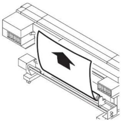
Technical diagram showing mechanical assembly and fluid flow (no text or symbols)- Pull out the fabric from the rear side of the printer to the height of the Y cover.
natural_image
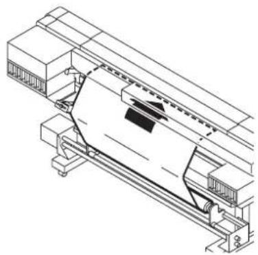
Technical line drawing of a printer or printer with a cover and arrow symbol (no text or labels)- Insert the leading edge of the fabric between the driver roller and pinch roller.
Be sure to lead the fabric outside the shaft of the centering sensor.
natural_image
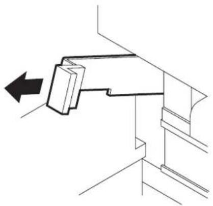
Technical line drawing of a mechanical assembly (no text or symbols visible)- Insert the roll fabric that has been pull out between the platen and the pinch rollers and pull it to the front of the printer.
natural_image
Technical line drawing of a mechanical assembly with a directional arrow indicating movement (no text or symbols)9. Pull out the leading edge of the fabric from the front face of the printer.

- Open the front cover, move up the clamp level while holding the leading edge of the fabric with your hand, then pull out the fabric.
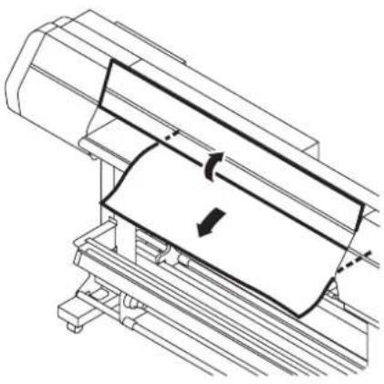
natural_image
Technical line drawing of a mechanical assembly with a clamped component and directional arrow (no text or symbols)10. Rewind the roll holder or fabric core several times from the rear face of the printer.
Make the fabric slack to alleviate the tension of the fabric.
NOTE!
- Do not pull the fabric directly, as this may cause wavy portion of the fabric.
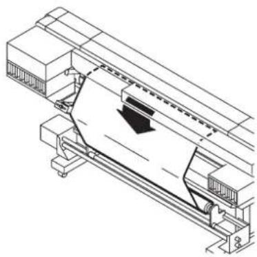
natural_image
Technical line drawing of a printer or printer with a paper airplane being inserted (no text or symbols present)11. M ove down the clamp lever on the front face of theprinter.
Secure the roll fabric pulled out to the front face, using the pinch roller.
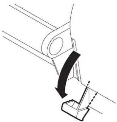
natural_image
Mechanical diagram showing a lever mechanism with a curved arrow indicating motion (no text or symbols present)Setting the centering sensor position
After setting the fabric to the printer, please set the centering sensor position.
NOTE!
- When adjusting the optical axis after the cloth width detection, the beep will not sound. Please make sure to adjust the centering sensor position before detecting the cloth width.
- Loosen the centering sensor securing screw.
- Align the arrow of the centering sensor with the edge of the fabric.

- Move the sensor unit. When the edge of the fabric intersects the sensor optical axis, a beep sounds. Stop the centering sensor arrow at the position where the first beep (a short beep) sounds. If a long beep sounds, the optimum position has been exceeded.
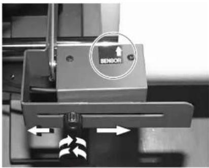
- Tighten the centering sensor securing screw to secure the sensor.

- If the edge of the fabric is curled, warped, or raised, the fabric pressers can be used to avoid damage to the ink head.
Attaching empty fabic core for taking up
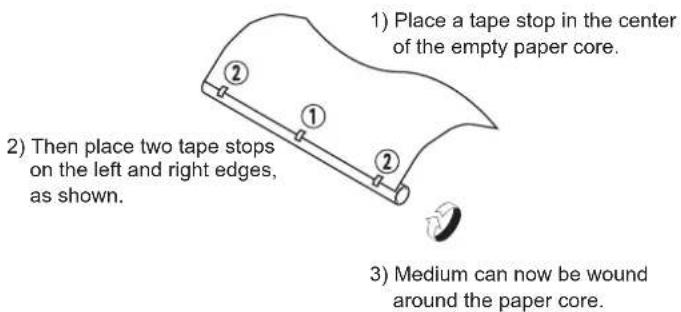
To take up the fabric after printing, attach an empty fabric core to the take-up device.
- Close the front cover to allow detection of the roll fabric.
- Push the JOG key [ ▲] and [▼] to move the leading edge of the fabric to the position of the empty fabric core.
- Using an adhesive tape, secure the leading edge of the fabric to the empty fabric core.
NOTE!
- When applying an adhesive tape, be sure to secure the center of the fabric first and then both edges. In this case, gently pull the fabric to prevent it from being slack.
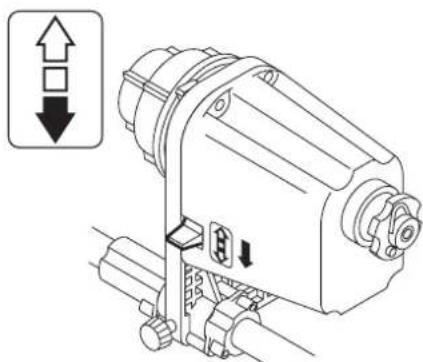
- Move down the switch of the take-up device.
natural_image
Technical line drawing of a mechanical device with directional arrows indicating movement (no text or symbols)NOTE!
- If you start printing before the leading edge of the fabric reaches the take-up device, black stripes may be printed which occur while the fabric correction value is negative.
Removing pinch roller and preventing wrinkle of fabic
NOTE!
- If either edge of the fabric stretches longer than the center or if an edge of the fabric is thickened because of gumming processing to prevent fray, slack may occur easily. In this case, remove the pinch rollers at both ends of the fabric.
STEP
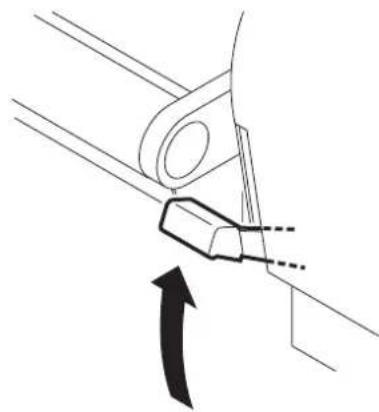
- Move up the clamp lever on the front face.
The pinch roller comes up.
natural_image
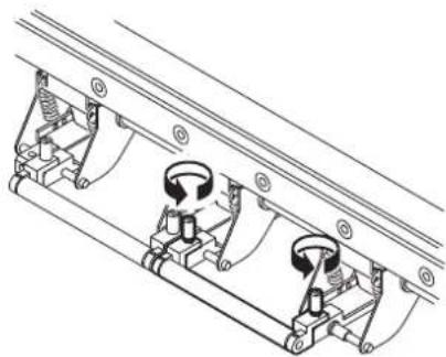
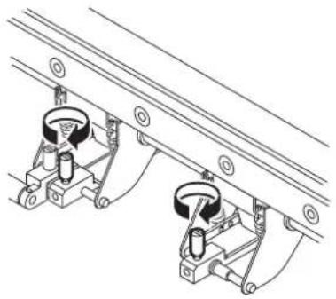
Technical diagram of a mechanical component with an arrow indicating direction (no text or symbols present)- Loosen the hand screws on both sides of the pinch roller to be removed.
natural_image
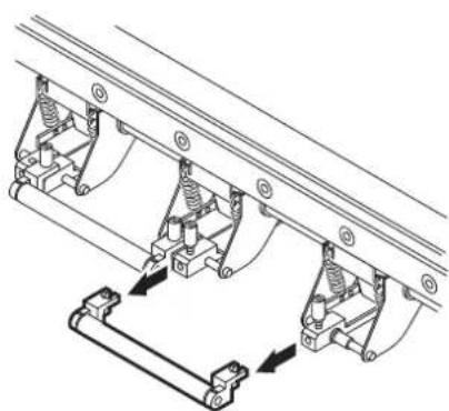
Technical line drawing of a mechanical assembly with two rotating components (no text or symbols)- Pull out the pinch roller.
natural_image
Mechanical assembly diagram showing three vertical supports connected to a bracket with directional arrows indicating motion (no text or symbols present)- To prevent fall-off or loss of the hand screws, lightly fasten them.
natural_image
Technical line drawing of two mechanical components mounted on a rail track (no text or symbols)NOTE!
- If the lengths of the fabrics at the left and right pinch rollers removed are different remarkably, reset the fabric. (See page 1.41)
Specifying the scope of printing on the fabric used (Effective printing area)
The printer has an area which cannot perform printing, due to mechanical reasons. This area is called “margin.”
The effective printing area is obtained by excluding the margin from the printing fabric.
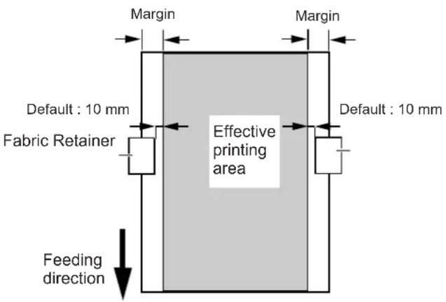
Roll Fabric

- The margin at the front and rear edges of the fabric can be reduced using a guiding fabric.
- The margin may be changed as required. The effective printing area can be changed by changing the margin. For the method of setting a margin, see page 3.15.
Origin setting
Establish an origin in terms of data on fabric loaded on the printer. Place the fabric and cause the printer to detect the fabric, the origin is automatically established at the location shown in the illustration given below.
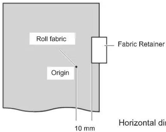
Horizontal direction : Position 10mm apart from the left edge of the fabric retainer
Setting of an origin
If you want to perform printing at another location of a roll fabric that provides a wider printing area, it is necessary to re-establish another origin.
STEPS:
- After the fabric detection is completed, press the JOG keys [▲], [▼], [ ] and [ ] to move the carriage to the position at which to set an origin.
As the carriage is moved, the origin shifts in position. The origin that changes with the movement of the carriage is displayed on the LCD.
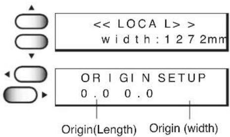
- After deciding the origin, press the [ENTER] key.
The origin has been changed.

Moving the printer
The method of moving the printer to the place of installation is explained below. When moving the printer, unlock the caster stoppers.
NOTE!
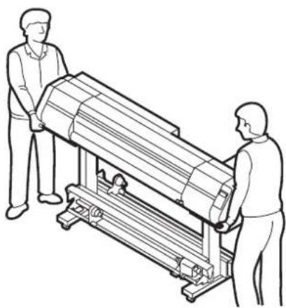
- When moving the printer take care not to apply excessive shock to it and it must be held up by at least two persons.
• After moving the printer, be sure to lock the caster stoppers.
STEPS:
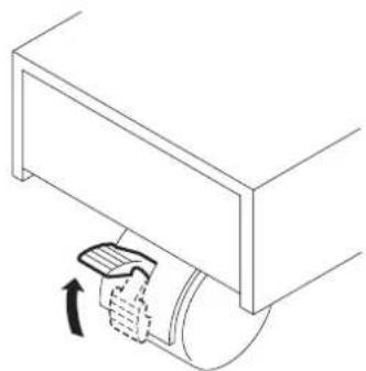
- Unlock each of the casters by raising up the caster stopper.
natural_image
Line drawing of a hand pressing down on a mechanical component (no text or symbols)- Hold up by at least two persons as illustrated at right.
NOTE!
- D o not press the front cover hard, it may be broken.
natural_image
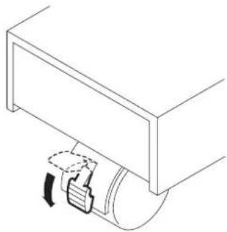
Line drawing of two people operating a large cylindrical device (no text or symbols present)- Lock each of the casters by moving down the caster stopper.
natural_image
Pure technical line drawing of a mechanical component with no text or symbolsChapter 2
How to use the basic functions
This chapter describes the basic operations of the printer, from the beginning to the end of printing.
Before using the application functions, understand how to use the basic functions of the keys on the operation panel and the modes in which the menus are displayed on the LCD.
Table of contents
Operation 2.2
Setting the display language 2.6
Printing an image from source data 2.7
Checking nozzle in ink firing condition 2.11
If there are nozzle clogging in ink firing condition 2.12
Routine maintenance 2.13
To replenish ink, set a new ink cartridge in the ink station 2.15
Operation
This section describes the operation panel that is used to operate the device and the menus from which to choose the desired item.
Operation panel
The operation panel that is used to operate the device and a method of maintenance of the device after operation, etc.
The operation panel must be used when operating the device.
Therefore, it is indispensable to understand how to use the operation panel.
JOG keys [][N][]
They are used to shift the carriage and the fabric under the LOCAL mode. In addition they are used to select a set value.
[TEST] key
Used to start test printing on the setting menu.
[FUNCTION] key
Used to set printing conditions.
[END] key
Used to cancel the last set item that has been input or to return to the previous setting menu.
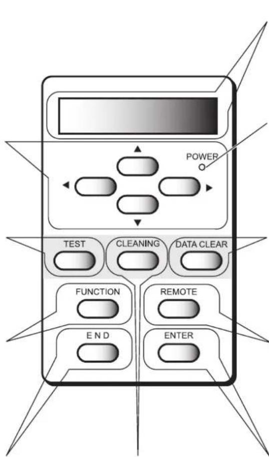
[CLEANING] key
Used to start cleaning of the head.
Display
Displays a set item, a guidance error, etc.
POWER lamp
It lights up (in green) when the power to the device is turned on.
[DATA CLEAR] key
Used to erase the data that has been input to the device.
[REMOTE] key
It is used to change the operation mode between the REMOTE mode and the LOCAL mode.
[ENTER] key
Used to input set items, such as printing conditions.
Functions of the JOG keys
Each of the JOG keys varies in function according to the time at which it is used.
The functions of the JOG keys are explained below.
| Before the detection After the detection When selecting of a sheet of a sheet function | a | When inputting a choice selected among several alternatives | |
 | Selects the roll media. Shifts the carriage to the left. | ||
 | Selects the leaf media. Shifts the carriage to the right. | ||
 | Shifts the fabric away Shifts the fabric away Restores the last Selects the next from you. from you. previous function. value. | ||
 | Moves the fabric toward Moves the fabric toward Moves to the next Selects the last you. you. function. value. | previous |
NOTE!
- Do not use reverse feed. (Move the fabric forward.)
The cloth may be caught by the platen and stained by set-off ink. Slack may occur at the run-out device and necessary tension may not be obtained when starting next printing. If you need to perform reverse feed, keep the above points in mind.
MENU mode
A list of setting items displayed on the LCD is called a menu.
A specific operation specified on the operation panel is displayed on the LCD in one of the following three modes.
Each of the three modes is explained below.
<> mode
This is the mode in which the preparations for printing operation are made.
When the power is switched on and the detection of a fabric is completed, the printer enters the LOCAL mode. In this mode, it is possible to perform the following operations.(See page 1.26)
- Pressing the appropriate [JOG] keys to detect a fabric and set up an origin.
- Pressing the [TEST] key to start test printing.
- Pressing the [CLEANING] key to clean the head.
- Pressing the [DATA CLEAR] key to erase the printing data the printer has received.
- Pressing the [FUNCTION] key to set printing conditions.
- Pressing the [ENTER] key to display the guidance.
NOTE!
- In the LOCAL mode, the printer cannot plot data received from the computer. To put the printer into operation, change the mode to the REMOTE mode by pressing the [REMOTE] key.
<< REMOTE >> mode
This is the mode in which the device plots an image from data it receives from the computer. If the mode is in the LOCAL mode, press the [REMOTE] key to put the mode into the REMOTE mode.
<> mode
This is the mode which printing conditions can be set.
To set printing conditions, press the [FUNCTION] key while the mode is in the LOCAL mode and switch to the FUNCTION mode (printing function setting mode).
Menu tree
The operation of printer and printing conditions are set by pressing the appropriate operation keys, selecting the desired setting item and setting detailed conditions.
In order to operate the printer properly, it is necessary to understand the structure of the menu tree (See page Appendix.5). The menu tree shown below makes plain the relationships between the operation keys on the operation panel and the functions that can be set by using them.
NOTE! • T o set any of the functions, the printer must be in the LOCAL mode.
STEPS:
(1) Turning the power on.(See page 1.26)
(2) Invoke the local mode on the LCD.
(3) To set up a specific function from the operation panel, follow the procedure shown below.
-
Press the appropriate operation key on the operation panel.
-
Select the desired setting item.
- Set up the desired function.
[Operation key] [Desired setting item] [Desired function]
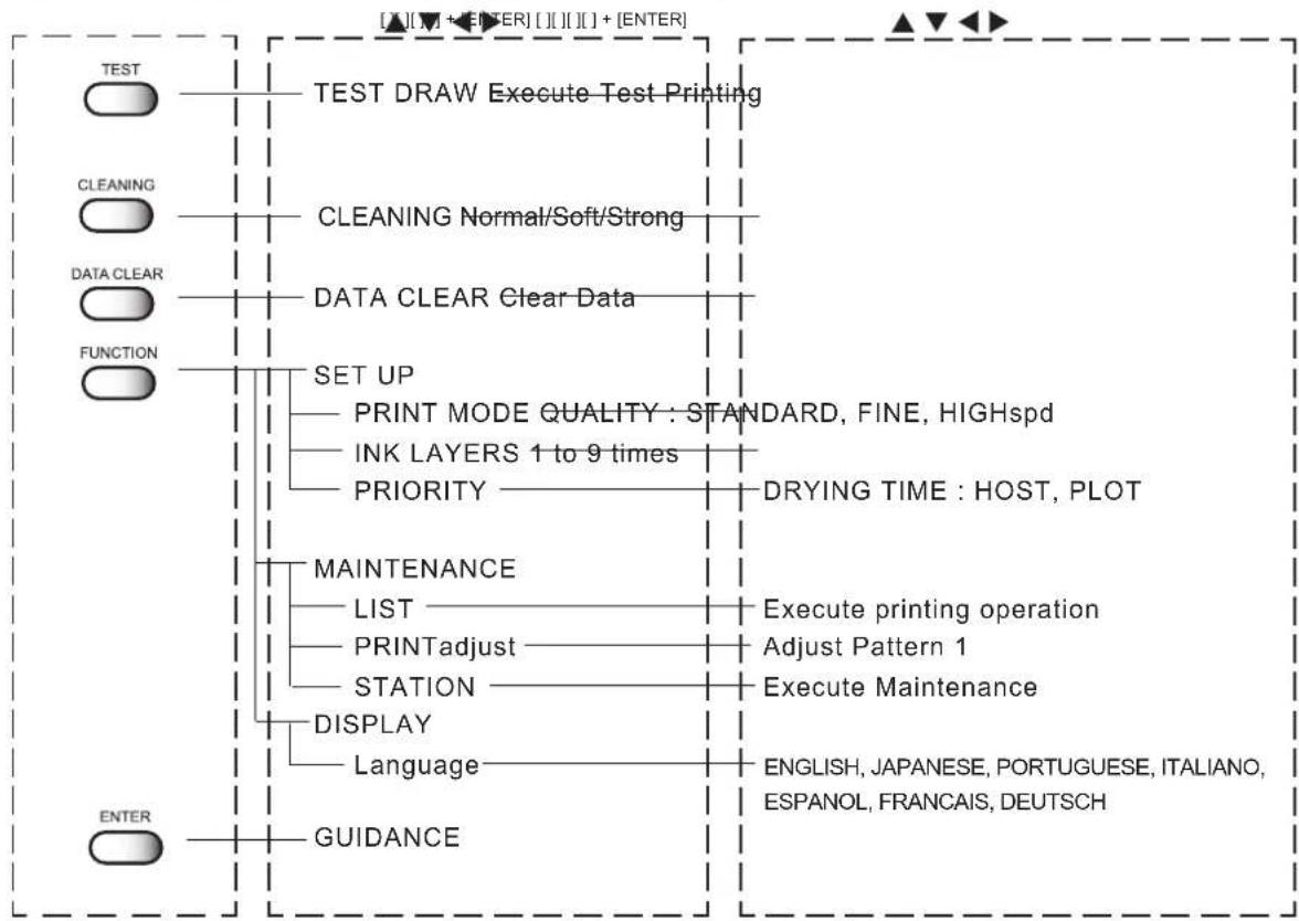
flowchart
graph TD
    A["TEST DRAW Execute Test Printing"] --> B["TEST DRAW"]
    C["CLEANING Normal/Soft/Strong"] --> D["CLEANING Normal/Soft/Strong"]
    E["DATA CLEAR Clear Data"] --> F["DATA CLEAR Clear Data"]
    G["FUNCTION SET UP"] --> H["PRINT MODE QUALITY: STANDARD, FINE, HIGHspd"]
    G --> I["INK LAYERS 1 to 9 times"]
    G --> J["PRIORITY —— DRYING TIME : HOST, PLOT"]
    K["MAINTENANCE LIST"] --> L["LIST —— Execute printing operation"]
    K --> M["PRINTadjust —— Adjust Pattern 1"]
    K --> N["STATION —— Execute Maintenance"]
    O["DISPLAY"] --> P["Language —— ENGLISH, JAPANESE, PORTUGUESE, ITALIANO, ESPANOL, FRANCAIS, DEUTSCH"]
    Q["GUIDANCE"] --> R["GUIDANCE"]

- The above shows menu trees in part. For details, refer to page Appendix.5.
Some menus simply list items which do not require the operator to set any of them. In this case, the operator is required to select the content to be displayed on the LCD.
[Operation key] DISPLAY
![Mimaki Tx2-1600 - [Operation key] DISPLAY - 1](/content/2026/05/919850/images/467ad8ada0903c4cc3219203d41a859f6c7363107f536921fbb545f919591ebd.jpg)
The operation mode is displayed.
![Mimaki Tx2-1600 - [Operation key] DISPLAY - 2](/content/2026/05/919850/images/fccbe6ee1c86268cedcae22a5069cd77d9bae9bcde88b428bc069118e778571f.jpg)
![Mimaki Tx2-1600 - [Operation key] DISPLAY - 3](/content/2026/05/919850/images/e0a0e5aa601a7aa47f3ee2b9047ff0fef9e246b7a724ce42af97a9cf27638f72.jpg)
The amount of ink that remains is displayed.
![Mimaki Tx2-1600 - [Operation key] DISPLAY - 4](/content/2026/05/919850/images/aaacc458ae9a7e17a1c1c0a6a2266352bd65bfe0040530d761b6d7455169fabd.jpg)
![Mimaki Tx2-1600 - [Operation key] DISPLAY - 5](/content/2026/05/919850/images/300f3d53ed3572bf22c09c72525fad1813f0ee463e72a222229fb0631e655c82.jpg)
The remaining amount and width of fabric is displayed.
![Mimaki Tx2-1600 - [Operation key] DISPLAY - 6](/content/2026/05/919850/images/a57fea715d495c0259969c74ef102a2db788168b0e969b4a5b929047faedc61e.jpg)
![Mimaki Tx2-1600 - [Operation key] DISPLAY - 7](/content/2026/05/919850/images/2c187a589bc86bbc3436e9f89fed4b85edbe60cb5bab3a35e3a3e2292666a710.jpg)
The type and number of ink being used is displayed.
![Mimaki Tx2-1600 - [Operation key] DISPLAY - 8](/content/2026/05/919850/images/1ec5a1a78d13d3913de353cecc78dd5bbd2a3340d91cfffbd7a62899ac943b85.jpg)
![Mimaki Tx2-1600 - [Operation key] DISPLAY - 9](/content/2026/05/919850/images/122d165e93bd39978ba54aa13eb01ed2f0835216900168e8433e1bea64b03001.jpg)
The height of head is displayed.

![Mimaki Tx2-1600 - [Operation key] DISPLAY - 11](/content/2026/05/919850/images/0e3db60f74953cb4d2bb41b977929941116d3fb0c0563ae5bba79e99728aea82.jpg)
The firmware version and command is displayed.
![Mimaki Tx2-1600 - [Operation key] DISPLAY - 12](/content/2026/05/919850/images/369f7b0bfba978e96b72d7764ab61003aa07016c30d71a544cd01238398f86d7.jpg)
![Mimaki Tx2-1600 - [Operation key] DISPLAY - 13](/content/2026/05/919850/images/74cad7624b8b543e50c50a300e951e60bdcaaa0d4866e3e4b1f9d3d13ecc982c.jpg)
The current setup condition is displayed.
![Mimaki Tx2-1600 - [Operation key] DISPLAY - 14](/content/2026/05/919850/images/f940b1d25f72b2231d22e321b05f0d1701c708d59bf3650d2bbf0bac81737f14.jpg)
![Mimaki Tx2-1600 - [Operation key] DISPLAY - 15](/content/2026/05/919850/images/4d389fbd84957292f0477d8994da4860fc6fea73a7678c5122e00b2338b94a7a.jpg)
The currently occurred errors are displayed.
![Mimaki Tx2-1600 - [Operation key] DISPLAY - 16](/content/2026/05/919850/images/e4d629068212165697bc4d7813e422c3ef7e09d59dbcfee0123289b3dc0101c2.jpg)
Setting the display language
Set the language in which to display characters on the LCD. "English" has been set as the initial display language of the printer. Try to change the display language to "Japanese" here.
STEPS:
- Make sure the mode is LOCAL mode.
Press the [REMOTE] key and put the menu back into the LOCAL mode.
<
width:1272mm
- Press the [FUNCTION] key.
FUNCTION

FUNCTION
SETUP
- Press the JOG key [▼] twice.

FUNCTION
DISPLAY
- Press the [ENTER] key.
ENTER

DISPLAY
ENGLISH
- Press the JOG key [] and [] to select the language to be used for the indication on the display.

DISPLAY
JAPANESE
There are seven different languages from which you can select one as the display language.
[ENGLISH], [JAPANESE], [PORTUGUESE],
[ITALIANO], [ESPANOL], [FRANCAIS], [DEUTSCH]

FUNCTION
DISPLAY
- After you have selected the display language, press the [ENTER] key.

- Press the [END] key.
Printing an image from source data
Starting the printer operation
This section describes the basic operation of the printer.
Printing conditions can be set on the printer side. In this section, however, the method of printing an image from data that has been set on the computer side and transmitted to the printer is explained.
For the method of setting printing conditions on the printer side, see Chapter 3 "How to Use the Application Functions."
STEPS:
1. Turn the power on.
(See page 1.26)
2. Set the fabric in position.
(See page 1.41)
After detecting the media, the menu enters the LOCAL mode.
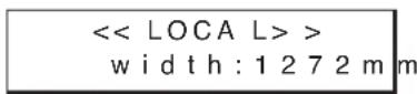
3. Press the [REMOTE] key.
![Mimaki Tx2-1600 - Press the [REMOTE] key. - 1](/content/2026/05/919850/images/0f0e85f10ba3ca2c268b987f20b4aeb7881261dcf73d222fd28816bdb88c5f29.jpg)
![Mimaki Tx2-1600 - Press the [REMOTE] key. - 2](/content/2026/05/919850/images/a38bca607ed49e69d76b0565b0db916a9857ddaa6aa43125ecedcf991375c081.jpg)
4. The printer receives the data from the computer.
The printing conditions that have been set for the data are displayed.
For the method of data transmission, see the manual for the output attached to the software.
5. Start the printing.
During the printing operation, the length of the fabric plotted on is displayed.
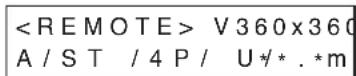


- If the data transmission breaks up for 30 seconds or more, the indication on the right will appear.

6. After the printing operation is completed, press the [REMOTE] key to put the mode back into the LOCAL mode.
![Mimaki Tx2-1600 - After the printing operation is completed, press the [REMOTE] key to put the mode back into the LOCAL mode. - 1](/content/2026/05/919850/images/6697404a637962988376acb8507baa175fd97d48802256aacbbc629f686e7090.jpg)
![Mimaki Tx2-1600 - After the printing operation is completed, press the [REMOTE] key to put the mode back into the LOCAL mode. - 2](/content/2026/05/919850/images/84af8095a88d445eb6db51215691bad7d1019bf2f7ee624d18ec40267481308f.jpg)
Information on printing data
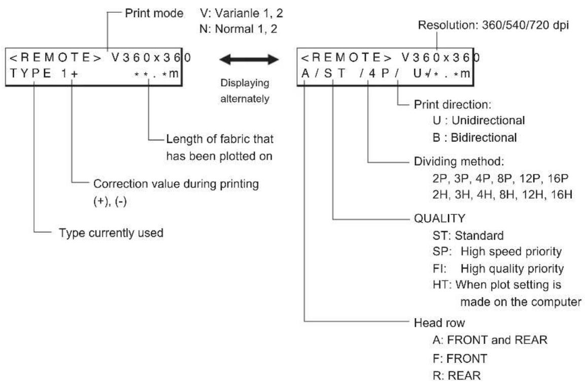
Key operation on REMOTE mode
[REMOTE] key : In case pressing [REMOTE] key when the printing data has not received, the mode is entered LOCAL mode. In case pressing [REMOTE] key when the printing data has received and printing has been performed, complete scan performance and the mode is entered LOCAL mode. Printing is suspended. And then press [REMOTE] key again, the mode is entered REMOTE mode and printing is started again.
[ENTER] key : When pressing [ENTER] key during REMOTE mode, the guidance is displayed.
[FUNCTION] key: When pressing [FUNCTION] key during REMOTE mode, the "Feed Comp." function is displayed.

- During the plotting performance is suspended, some function could not be operated and the error will be displayed as follows:
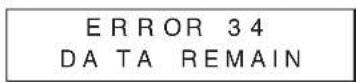
In this case, complete plotting operation or execute "DATA CLEAR" operation.
Correcting the media feed rate during printing [Feed Comp.]
Even for fabric of the same type, if the thread size or texture is slightly different, the proper value of the feeding amount changes.
In this case, correct the feeding amount of the fabric while checking the printing condition.
NOTE!
- To change the fabric type or print data, be sure to perform [Feed Comp.].
- During [Feed Comp.] printing, does not print correction patterns. Perform only correction value input operation while checking print data.
STEPS:
1. Press the [FUNCTION] key on REMOTE mode.
The current setting value can be confirmed.
Press the [END] key when an appropriate value is set or to abort the operation.
![Mimaki Tx2-1600 - Press the [FUNCTION] key on REMOTE mode. - 1](/content/2026/05/919850/images/d7e9ce3f73adefa24f598b7b5074107045aea2e411eabd25906c5c705fe5a681.jpg)
FEED COMP. - 200 ADJUST : en t
2. Press the [ENTER] key.
Available to alter the fabric feed rate.
![Mimaki Tx2-1600 - Press the [ENTER] key. - 1](/content/2026/05/919850/images/cec718e4448c96c6cb3567922f1dcf8517c9d865913e5edf9ef7e7a93c370663.jpg)
FEED COMP. - 200 ADJUST = 100
3. Press the JOG key [] or [] as needed to set the amount of correction.
Setting value is available from -500 to +500. Press [END] key to return to the REMOTE display. The altered value ceases to be in effect, and returns to the previous value.
![Mimaki Tx2-1600 - Press the JOG key [] or [] as needed to set the amount of correction. - 1](/content/2026/05/919850/images/959acbf0e3a4736d74d0d441d52b309b8d6c39c2f6bf2673c4717c605a643000.jpg)
FEED COMP. - 200 ADJU ST = 100
![Mimaki Tx2-1600 - Press the JOG key [] or [] as needed to set the amount of correction. - 2](/content/2026/05/919850/images/7d873403c1e43c415593bb8ecadb3868736ecfa5717e55c4f3c25ae5d3cf0af0.jpg)
- A new value takes effect in real time. The best effect can be obtained while checking the result.
- Make judgment from the result obtained after 4 scans (for 4-pass printing) or 8 scans (for 8-pass printing).
- The unit of the correction value is the same as in "Media Comp." in the LOCAL mode.
- Setting value is to be Reset as follow,
*Perform the "MEDIA COMP."
*Perform the "SETUP RESET"
4. Press the [ENTER] key.
Confirm the fabric feed rate before saving it.
![Mimaki Tx2-1600 - Press the [ENTER] key. - 1](/content/2026/05/919850/images/a461db427c3b897e78eb8c0ed1889a4497257a7a8ac7cc3d66b345b8b9b38ccc.jpg)
FEED COMP. - 100 SAVE : en t
5. Press the [ENTER] key to return to the REMOTE display.
The changed setting value is saved. The value is to be in effect performing till the turning off.
Press the [END] key to return to the REMOTE display. The changed setting value is to be in effect performing till the turning off.
![Mimaki Tx2-1600 - Press the [ENTER] key to return to the REMOTE display. - 1](/content/2026/05/919850/images/5710145ba659991ff92953f52d248320b5e5ad367c8b971db77bb4b17e4b8dbe.jpg)
![Mimaki Tx2-1600 - Press the [ENTER] key to return to the REMOTE display. - 2](/content/2026/05/919850/images/f3a69a034e21673e640a5430e0a818c149c4380325b0132c108f11d9079fe30a.jpg)
- In case the setting value has changed before, the indicate gives [+] mark beside of the TYPE. In the same way, the indicate gives [-] mark beside of the TYPE when the setting value has changed.
Interrupting the printing operation
To interrupt the printing operation that has been started, stop the carriage and erase (the receive data) from the printer.
STEPS:
- Press the [REMOTE] key to stop the printing operation.
- If data is being transmitted from the computer to the printer, stop the data transmission.
- Press [DATA CLEAR] key.
The data that has been received is erased.
DATA CLEAR DATA CLEAR
- Press [ENTER] key.
Checking nozzle in ink firing condition
Executing the test draw [TEST DRAW]
In prior to the actual printing or after the execution of the cleaning function, a test pattern is plotted to check whether the finished test pattern has blurred and missing lines on test pattern)
![Mimaki Tx2-1600 - Executing the test draw [TEST DRAW] - 1](/content/2026/05/919850/images/84acfcd46848f814bc72a5db9b1b31138c773823c3fda8f495e4ed96db8c7da9.jpg)
- If the finished test pattern shows any sign of abnormal conditions, carry out the cleaning function. (See page 2.12)
STEPS:
1. Make sure the mode is LOCAL mode.
Press the [REMOTE] key and put the device back into the LOCAL mode.

2. Press the [TEST] key.

3. Press the [ENTER] key.
After printing the test patten the device enters the LOCAL mode.
![Mimaki Tx2-1600 - Press the [ENTER] key. - 1](/content/2026/05/919850/images/384aef7b5af0994c12c90c0bd38d282c562055a74544590b204d486c401c1292.jpg)
![Mimaki Tx2-1600 - Press the [ENTER] key. - 2](/content/2026/05/919850/images/2ef33aeff337baebc48b4eb12aa8f2b418fda56960979a238eab9201be6d9fcb.jpg)
- This function can be executed even during host data printing. In this case, however, some host data will be missing. The amount of missing data depends on the medium width, number of paths, resolution, and data transfer rate of the host.
![Mimaki Tx2-1600 - Press the [ENTER] key. - 3](/content/2026/05/919850/images/e989f9bc7cb5f9041fc0f03e0c2704cb643e989e13b3d1f5df9c6e3531754c68.jpg)
4. When test printing is performed during host data printing, press the [REMOTE] key.
![Mimaki Tx2-1600 - When test printing is performed during host data printing, press the [REMOTE] key. - 1](/content/2026/05/919850/images/e3463572ad1fb0fd135a0c851e7efec5872339c07092bebe6fcc349c2c35b69b.jpg)
The printer enters the REMOTE mode
Checking the test patterns
The printer plots a test pattern for each of the ink head. Check the test pattern to determine whether or not the ink head need cleaning.
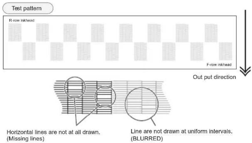
If there are nozzle clogging in ink firing condition
Cleaning ink heads
If a test pattern plotted is defective, execute the cleaning function to clean the associated ink head. After cleaning the ink head, make the device plot a test pattern again. If the test pattern is defective too, re-clean the ink head. Continue executing the cleaning function till a normal test pattern is obtained.

- If a normal test pattern cannot be obtained even after the cleaning function is executed many times, clean the ink station interior (See page 4.8).
soft: Select this if there is any missing line. Cleaning is carried out for a short period of time.
normal: Select this if any line is bent. Cleaning is carried out for a long period of time and a large amount of ink is consumed.
strong: Select this if there are many missing portions.
STEPS:
- Make sure the mode is LOCAL mode.
- Press the [CLEANING] key.
- Press the JOG keys [ ▲] [▼] [ ] and [ ] to select the ink head to be cleaned.
Each time a JOG key is pressed, the row of heads to be cleaned changes from R to F (or F to R). The upper eight of test printing indicates the R row of heads, and the lower eight indicates the F row of heads.
4 types of head row can be selected: [1234], [5678], [ABCD], and [EFGH].
- Press the [ENTER] key.
- Press the JOG keys [] and [] to select the type of cleaning.
- Press the [ENTER] key.
Cleaning starts.
The remaining time to cleaning is displayed on the second line of LCD.
After completing the cleaning performance, the mode enters the LOCAL mode.


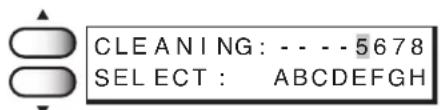
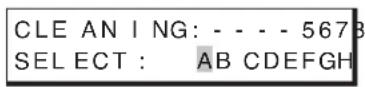

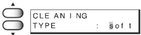


Routine maintenance
Be sure to conduct maintenance works for the device when necessary or periodically so as to use the printer for a long time while keeping its printing accuracy.
When the device is left unused for a long period of time
NOTE!
- Turn off the power.
- Remove the fabric that has been set on the printer.
- Keep the clamp lever move up.
Notes on cleaning
CAUTION
- Never disassemble the printer. Disassembling the printer can result in electric shock hazards and breakage of the printer.
- Prevent moisture from entering inside the printer. If the inner part of the printer becomes wet, electric shock hazards and breakage of the printer can result.
CAUTION
- Do not use benzine, thinner and chemical agents containing abrasives. Such materials can deteriorate or deform the surface of the cover.
- Do not apply lubricating oil or the like inside the printer. Such materials can cause the printer mechanism to fail.
Cleaning ink at the bottom of the slider
When the printer have been used for a long period of time, glued ink may accumulate at the bottom of the slider. Leaving this condition allows ink drops to grow and may cause contamination of the fabric. Clean the bottom of the slider periodically to remove ink drops using the supplied swab dampened with water.
In this case, be careful not to brush the head nozzle. (See page 4.23, STEP 5.)
Cleaning wiper
The wiper is stained by dirt and ink while you use it. If you clean the head when the wiper is dirty, you may get the head dirty.
Clean the wiper periodically.
For the procedure for cleaning the wiper, refer to page 4.10.
Cleaning the wiper shaft
The dirty wiper shaft may cause the wiper malfunction and resulting an error display.
Maintenance for frame components
If the frame components of the device have stained, dampen a piece of soft cloth with water or neutral detergent diluted with water, squeeze it and wipe the frame components clean.
Cleaning penetrated ink
When printing on a thin cloth, ink is collected in the ditch.
Make sure to wipe them with wasted cloth frequently. If ink is left in the ditch, ink leaks and smadges floor or machine inside.
Place to wipe:
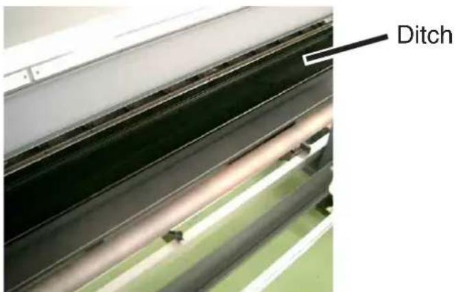
Frequeincy of wipe:
- When operation end each day, or when replacing the media.
• In the case of continuous printing, or using a loose weave fabric, ink is collected faster.
Therefore be sure to wipe when ink in the ditch go into liquid state.

- laying a waste cloth in the ditch makes cleaning easier. Replace the cloth when certain amount of ink has been absorbed.
To replenish ink, set a new ink cartridge in the ink station
Setting a new ink cartridge is required when the ink is to be replenished or when the device becomes the following condition.
If the ink cartridge is not replaced, the carriage stops during the printing operation when the ink runs out.
When the message [Ink Near End] is displayed on the LCD, install a new ink cartridge without delay.
- When the amount of ink becomes small during printing.
The amount of ink of the cartridge number indicated is running out.
Load a new ink cartridge into Slot 1 of the left ink station.
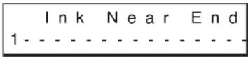
- When the amount of ink completely runs out during printing.
The amount of ink of the cartridge number indicated has completely run out.
Install a new ink cartridge into Slot C of the right ink station.
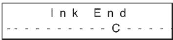
STEPS:
1. Either of the messages shown above is displayed on the LCD during printing.
The printing operation is not interrupted even when [Ink Near End] is displayed. Proceed to Step 2 at the end of the printing operation.
If [Ink End] is displayed, the carriage stops during the printing operation. In this case, the printing operation is interrupted.
2. Install a new ink cartridge.
Pull out the ink cartridge of the indicated color and then set a new ink cartridge.

- To set a new ink cartridge of an ink type different from the one being used, see Chapter 4 "Maintenance Functions" (See page 4.26).
Chapter 3
How to use the application functions
After you have mastered the operations described in Chapter 2 “How to use the basic functions,” you should learn how to use the application functions whereby you can set printing conditions on the printer side and put the printer into operation.
By using the application functions, you can set printing conditions appropriate to data that is provided for the printing operation.
Table of contents
Application functions 3.2
Before setting printing conditions in the function menu 3.3
Adjusting the lapal bar 3.5
After setting the fabric to be printed 3.7
Setting printing conditions 3.8
Improving the density of ink color [INK LAYERS] 3.11
Setting the ink drying time [DRYING TIME] 3.12
Deciding the priority of settings by the computer or the plotter [PRIORITY] ..... 3.13
Increasing (decreasing) the right and left margins of the fabric [RIGHTmargin]/[LEFTmargin] 3.15
When using the plotter in an extremely dusty or dry place [REFRESH] 3.17
Setting a unit of length displayed on the LCD [MM/INCH] 3.18
Setting the type of ink to be used [INK TYPE] 3.19
Setting up auto-cleaning function [AUTO CLEAN] 3.20
Setting up auto-cleaning function [AUTO CLEAN2] 3.21
Setting of End of printing [EndOf PRINT] 3.23
Continuing printing after [Ink Near End] [PRINT CONT.] 3.24
Preventing the fabric skew [CENTERING] 3.25
Enabling the take-up unit [TAKE-UP].... 3.26
Resetting printing conditions by type [SETUP RESET] 3.27
Application functions
The application functions make it possible to modify the printing conditions that have been set for source data received from the computer. The [FUNCTION] key is used to set up the application functions.
Function menu
Of the menus that are provided for setting printing conditions for the printer, the menu for setting up the printer functions is called the function menu. In order to set printing conditions properly, it is necessary to understand the structure and operation of the function menu.
The function menu consists of three major items: [SETUP], [MAINTENANCE], and [DISPLAY]. In this chapter, [SETUP] and [DISPLAY] of the function menu are explained. (For "Maintenance" of the function menu, see Chapter 4 "Maintenance functions.")
[SETUP]/[DISPLAY]
The table, below, shows the tree structure of the function menu.
In order to use the application functions of the printer, it is necessary to understand the proper sequence of key operations.
In setup of the function menu, allocate printing methods to be set to types 1 to 4 before detailed setting of the individual printing conditions so that you can use the printing conditions registered by type.
![Mimaki Tx2-1600 - [SETUP]/[DISPLAY] - 1](/content/2026/05/919850/images/bc1c300de559a61b44a51409c05b08904cefb908aabdf33b69f792e98035a492.jpg)
flowchart
graph TD
    A["[FUNCTION"] SET UP] --> B["TYPE1 to 4 MEDIA COMP. -500 to 500"]
    B --> C["PRINT MODE"]
    C --> D["QUALITY"]
    D --> E["STANDARD, FINE, HIGHspd"]
    C --> F["DIRECTION UNLD, BI-D"]
    C --> G["RET, SPD UP-ON, OFF"]
    C --> H["INK LAYERS 1 to 9"]
    H --> I["DRYING TIME EACH LINE: 0.1s to 9.9s"]
    H --> J["AUTO CUT OFF, ON"]
    H --> K["PRIORITY"]
    K --> L["PLOT MODE : HOST, PLOT"]
    L --> M["INK LAYERS : HOST, PLOT"]
    L --> N["DRYING TIME : HOST, PLOT"]
    N --> O["INK TYPE : HOST, PLOT"]
    N --> P["REFRESH : HOST, PLOT"]
    K --> Q["MARGIN"]
    Q --> R["RIGHTmargin -9 to 95mm"]
    R --> S["LEFTmargin =9 to 95mm"]
    Q --> T["REFRESH LEVEL: 0 to 3"]
    T --> U["MM/INCH"]
    U --> V["INCH, MM"]
    V --> W["INK TYPE"]
    W --> X["Acid, Disp, Reac (Displayed at the time of setting for 2-way multiprocessing.)"]
    W --> Y["AUTO CLEANING"]
    Y --> Z["OFF, ON"]
    Y --> AA["AUTO CLEANING2"]
    AA --> AB["OFF, ON"]
    AA --> AC["normal, soft, strong"]
    AA --> AD["0.1 to 10m"]
    AA --> AE["PRINT CONT. OFF, ON (Displayed at the time of setting for 1-way high-speed printing.)"]
    AA --> AF["EndOf PRINT"]
    AF --> AG["BACKFEED"]
    AG --> AH["OFF, ON"]
    AG --> AI["1 to 60mm"]
    AG --> AJ["CENTERING OFF, ON"]
    AJ --> AK["TAKE-UP"]
    AK --> AL["OFF, ON, INTERVAL, SETUP RESET"]
    AK --> AM["RESET"]

    A --> AN["[FUNCTION"] MAINTENANCE]
    AN --> AO["See Chapter 4 "Maintenance Functions"."]
    A --> AP["[FUNCTION"] DISPLAY]
    AP --> AQ["ENGLISH, JAPANESE, PORTUGUESE, ITALIANO, ESPANOL, FRANCAIS, DEUTSCH"]
Before setting printing conditions in the function menu
The basic operation of the function menu for setting individual printing conditions is explained below. Set the individual printing conditions in the function menu after performing the following three operations.
- Check that the menu mode is the LOCAL mode.
- Check that the language in which to display characters on the LCD has been selected.
- Select a Type to register the sequence of set printing conditions.
Before setting the printing conditions in the function menu, confirm the basic operations and then set the individual printing conditions described on the pages that follow.
Checking the menu mode
Check the menu mode before setting the printing conditions.
The menu mode must be either the LOCAL mode or the FUNCTION mode.
Check also that the mode displayed on the LCD is either <
Registering Two or More Printing Conditions at a Time (Selecting a Type)
Register a sequence of printing conditions set in the FUNCTION mode in the memory of the printer. By allocating the sequence of printing conditions to any of Types 1 through 4, it is possible to reuse the same printing conditions registered by type. It is, therefore, convenient to allocate different printing conditions to different types according to the fabric and printing method used.
The procedure for allocating a specific sequence of printing conditions to a type is described below. Here, the method of registration by allocating printing conditions to a particular type is explained.
STEPS:
-
Make sure that the mode is LOCAL mode.
-
Press the [FUNCTION] key.
-
Press the [ENTER] key.
-
Press the JOG keys [ ▲] and [▼] to select any of Types 1 through 4.
There are four types which you can select.
[Type.1], [Type.2], [Type.3], [Type.4]
- Press the [ENTER] key.
Setting Printing Conditions.
(See page 3.7 through 3.27)
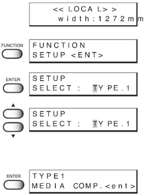
<
width:1272m
m
FUNCTION
SETUP
SETUP
SELECT : TYPE.1
SETUP
SELECT : TYPE.1
TYPE1
MEDIA COMP.
Changing the type
Note that the current type cannot be changed while the device is in operation.
To change the type during printer operation, first stop the device (See page 2.10) and then select the desired type in the LOCAL mode.

- Only the setting of the following items can be changed during printing.
[MM/INCH], [MEDIA COMP.], [TAKE-UP], [CENTERING]
If you attempt to change the setting of other items during printing, the following error message appears.
ERROR 34 DATA REMAIN
Adjusting the lapal bar
Diverse types of media are used for inkjet printers: different raw materials including natural materials, synthesized materials, etc. and materials with different manufacturing processes including textile fabric, knit fabric, etc. In addition, even for the same medium, the elasticity characteristic changes according to the difference in pre-treatment, etc. To perform printing on diverse types of media with appropriate tension which best suits each medium, it is necessary to adjust the mount position of the lapel bar and the number of bars mounted.
CHANGING THE WINDING ANGLE OF THE LAPEL BAR >
| High-tension media setting Low-tension media setting | |
| Larger contact angle increases the tension. | Smaller contact angle decreases the tension. |
CHANGING THE WINDING ANGLE OF THE LAPEL BAR >
| Media set 1 Media set 2 | |
| [2] [3] [1] [3] [1]Set a lapel bar. [2]Set the medium. [3]Set two lapel bars. | [2] [1] [3] [1]Effective to increase the contact angle. [1]Set two lapel bars. [2]Set the medium. [3]Set a lapel bar. |
Troubleshooting
The following describes general troubleshooting. With some corrective mesures, problems may not be solved depending on the media used. If a problem cannot be solved after performing test printing several times, stop using the printer.
| No. | Problems Corrective | measures Remarks | |
| 1 | B lack lines occur. 1. | Increase the media correction value.2. Reduce the resistance of lapel bar.Reduce the number of lapel bars.Change the mount position of the lapel bar so that the contact angle of the medium be decreased.(Refer to the previous page.) | This problem occurs with media which shrink when printed. |
| 2 | White lines occur. 1. Reduce the media correction value.2. Increase the resistance of the lapel bar.Increase the number of lapel bars.Change the mount position of the lapel bar so that the contact angle of the medium be increased. (Refer to the previous page.) | This problem occurs with media which strech when printed. | |
| 3 | Wrinkles occur on the medium near the pinch roller. | 1 .Reduce the number of lapel bars.Change the mount position of the lapel bar so that the contact angle of the medium be decreased.(Refer to the previous page.) | This problem occurs mainly with curved media and media with local slacks. |
| 4 | Black and white lines occur at random. | 1 .tube or curved one is used.: Replace the paper core.2. Change the mount position of the lapel bar. Refer to the corrective measures of No.1 (black lines) and No.2 (white lines).3. Check whether the fabric is skewing.:Reset the roll.4. Check whether the edge of roll is aligned.: Rewind and reset the roll. | This problem occursCheck mainly with the media pre-treatment has not done evenly, or the media easy to stretch when pulled. |
After setting the fabric to be printed
Correcting error of amount of feed depending on fabric [MEDIA COMP.]
The printer prints an image on the fabric while feeding it forward little by little.
When the thickness of the fabric changes, the optimum feed rate changes accordingly. If this occurs, the printer may not print a clear image (e.g., unwanted stripes may appear on the image). To correct the fabric feed rate according to the fabric thickness, execute this function and make a printing test.
STEPS:
1. Select a type.
(See page 3.3). Here, select [Type.1].
2. Press the [ENTER] key.
3. Press the [ENTER] key.
4. Press the [ENTER] key.
Test printing for correction of the fabric feed rate starts. Seven types of fabric correction patterns are printed.
5. Enter a correction value from the output pattern.
Press the JOG keys [▲ and [ ]▼ to enter the correction value. If the printed pattern has a gap between lines: Select the minus value. If lines of the printed pattern overlap: Select the plus value.
6. Press the [ENTER] key.
7. Press the [END] key twice.
The menu returns to the LOCAL mode.
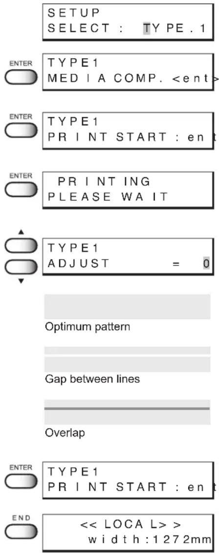
Setting printing conditions
Changing printing conditions on the printer side
Set up the printing method that determines the quality of image.
For the printing method, there are three setting items - "quality of image", "direction of printing" and "Returning speed of the head."
Relationship between image quality and printing speed [QUALITY]
For the quality of image, there are three setting items - [STD], [FINE], and [HIGHspd].
[STD] (Standard) : Standard image quality
[FINE] : High image quality and low printing speed
[HIGHspd] (High speed) : High printing speed and slightly inferior image quality
STEPS:
- Select a type. (see page 3.3).
Here, select Type 1.
-
Press the [ENTER] key.
-
Press the JOG keys [ ▲] and [▼ to select [PRINT MODE].
-
Press the [ENTER] key.
-
Press the [ENTER] key.
-
Press the JOG keys [▲] and [▼to select the quality.
There are three quality types from which you can select one.
[STD], [FINE], [HIGHspd.]
-
Press the [ENTER] key.
-
Press the [END] key three times.
The menu returns to the LOCAL mode.
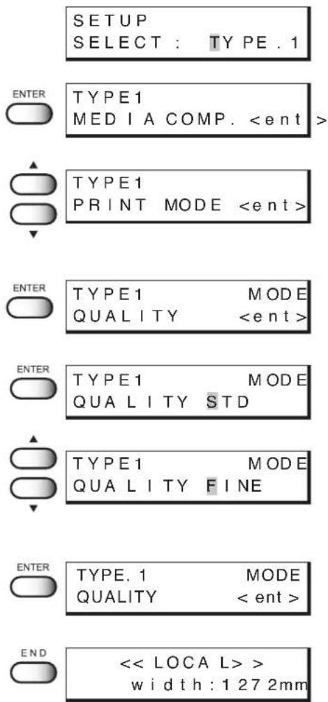
Printing direction [DIRECTION]
This function sets the direction of printing.
The printer prints an image while moving the carriage right and left. By setting the direction of printing, it is possible to adjust the image quality and the printing speed: "Uni-directional" and "Bi-directional."
UNI-D : The image is printed only in one direction during movement of the carriage.
Image quality is better than when BI-D is specified.
BI-D: The image is printed in both directions during movement of the carriage.
Image quality slightly deteriorates since emphasis is placed on printing carriage.
STEPS:
- Select a type. (see page 3.)
Here, select [Type.1].
-
Press the [ENTER] key.
-
Press the JOG keys [ ▲] and [▼to select [PRINT MODE].
-
Press the [ENTER] key.
-
Press the JOG keys [ ▲] and [▼to set a printing direction [DIRECTION] .
-
Press the [ENTER] key.
-
Press the JOG keys [ ▲] and [▼to set a printing direction [UNI-D] or [BI-D].
Here, select [UNI-D].
-
Press the [ENTER] key.
-
Press the [END] key three times.
The menu returns to the LOCAL mode.
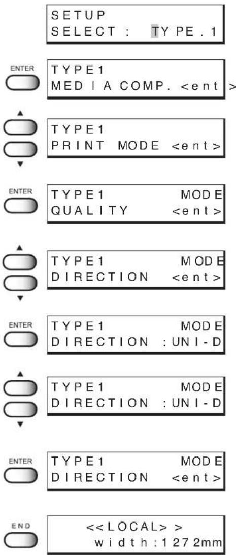
Returning speed up [RET. SPD UP]
In case the printing width is 1000mm or less when uni-directional printing, the nozzle drop out may occur. Using this function to slow down the returning head speed may solve the trouble.
ON : The head returns with normal speed.
OFF : The head returns with slow speed.
STEPS:
- Select a type. (see page 3.3)
Here, select [Type.1].
-
Press the [ENTER] key.
-
Press the JOG keys [ ▲] and [▼ to select [PRINT MODE].
-
Press the [ENTER] key.
-
Press the JOG keys [ ▲] and [▼ to select [RET.SPD UP] .
-
Press the [ENTER] key.
-
Press the JOG keys [▲] and [▼] to set a returning speed [ON] or [OFF].
Here, select [OFF].
-
Press the [ENTER] key.
-
Press the [END] key three times.
The menu returns to the LOCAL mode.
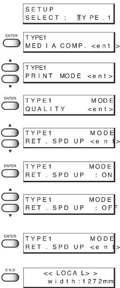
Improving the density of ink color [INK LAYERS]
This function prints the data in two or more layers (wet-on-wet coating) to improve the density of ink color.
If a coarse-surfaced fabric (e.g., canvas) is used, the color of ink might be weak. In this case, execute this function (wet-on-wet coating).
NOTE!
- When using a cloths with high moisture-elasticity, do not use the function [INK LAYERS]. The printing quality may be reduced because of expansion and contraction of the cloth, or the head may catch the cloth to press it to a position resulting in cloth jam.
STEPS:
- Select a type. (see page 3.3)
Here, select [Type.1]. - Press the [ENTER] key.
- Press the JOG keys [▲] and [▼] to select [INK LAYERS].
- Press the [ENTER] key.
- Press the JOG keys [ ▲] and [▼] to select the number of ink layers.
A number 1 to 9 can be selected as the number of times of reprinting.
Here, select [3] times.
-
Press the [ENTER] key.
-
Press the [END] key twice.
The menu returns to the LOCAL mode.
SETUP SELECT : TYPE . 1

TYPE1
MEDIA COMP.
TYPE1
INK LAYERS

TYPE1 INK LAYERS = 1
TYPE1 INK LAYERS = 3

TYPE1
INK LAYERS

Setting the ink drying time [DRYING TIME]
This function sets an ink drying time.
The drying time is the wait time by scanning and the time interval between the instant at which the printing operation is completed.
Specify the time to be established in accordance with the printing resolution on a drawing and the type of fabric to be used.
STEPS:
- Select a type. (see page 3.3)
Here, select [Type.1]. - Press the [ENTER] key.
- Press the JOG keys [ ▲] and [↓ to select [DRYING TIME].
- Press the [ENTER] key.
- Press the JOG keys [▲] and [↓] to set a drying time after the scanning.
This is the drying time from the instant at which the carriage returns to the capping station till the instant at which the carriage starts moving again for printing. The drying time that can be set is 0.0 second to 9.9 seconds.
Here, select 1.0.
-
Press the [ENTER] key.
-
Press the [END] key twice.
The menu returns to the LOCAL mode.


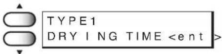

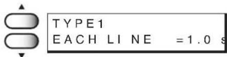


Deciding the priority of settings by the computer or the plotter [PRIORITY]
This function gives priority to either the printing conditions set on the computer or the printing conditions set on the plotter.
Printing conditions can be set on data of the plotter and on data received from the computer using the output software. If these printing conditions differ, priority is given to either of them at the time when the printing operation is started.
HOST : The printing operation is performed with priority given to the printing conditions set on the computer.
PLOT : The printing operation is performed with priority given to the printing conditions set on the plotter.
Priority needs to be specified for each of the following items:
- PRINT MODE • INK LAYERS • DRYING TIME
- INK TYPE • REFRESH • MEDIA COMP.
STEPS:
- Select a type. (See page 3.3)
Here, select [Type.1].
-
Press the [ENTER] key.
-
Press the JOG keys [ ] and [ ] to select [PRIORITY].
-
Press the [ENTER] key.
-
Press the JOG keys [▲] and [▼] to select the priority [HOST] or [PLOT] of the print mode. Here, select [PLOT].
-
Press the [ENTER] key.
-
Press the JOG keys [ ▲] and [▼] to select the priority [HOST] or [PLOT] of the ink layers. Here, select [PLOT].
-
Press the [ENTER] key.
SETUP SELECT : TYPE.1

TYPE1
MEDIA COMP.
TYPE1
PRIORITY

TYPE1 PRINT MODE :HOST
TYPE1 PRINT MODE :PLOT

TYPE1 INK LAYERS :HOST
TYPE1 INK LAYERS :PLOT

TYPE1 DRYING TIME :HOST
- Press the JOG keys [ ▲] and [▼] to select the priority [HOST] or [PLOT] of the driying time. Here, select [PLOT].
- Press the [ENTER] key.
- P ress the JOG keys [▲] and [▼ to select the priority [HOST] or [PLOT] of the ink type. Here, select [PLOT].
- Press the [ENTER] key.
- Press the JOG keys [▲] and [▼] to select the priority [HOST] or [PLOT] of the refresh. Here, select [PLOT].
- Press the [ENTER] key.
- Press the JOG keys [▲ and [ ]▼ to select the priority [HOST] or [PLOT] of the media comp. Here, select [PLOT].
- Press the [ENTER] key.
- Press the [END] key twice. The menu returns to the LOCAL mode.
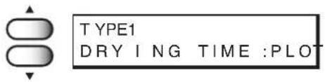

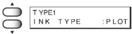

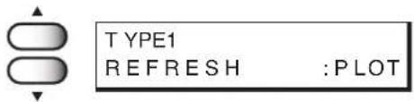

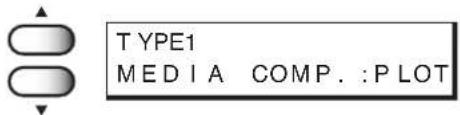


Increasing (decreasing) the right and left margins of the fabric [RIGHTmargin]/[LEFTmargin]
This function sets an effective printing area to increase/decrease the right and left margins of the fabric. The blank portion of the fabric is called maigin. (See page 1.49)
The function is used to increase the margin for binding.
You can set a margin for each of the right and left margins of the fabric.
Setting [RIGHTmargin]
STEPS:
- Select a type. (See page 3.3)
Here, select [Type.1].
-
Press the [ENTER] key.
-
Press the JOG keys [ ▲] and [▼ to select [MARGIN].
-
Press the [ENTER] key.
-
Press the [ENTER] key.
-
Press the JOG keys [ ▲] and [▼] to set a maigin.
You can set a margin in the range -9 mm to 95 mm in mm unit. Here, set [10 mm].
-
Press the [ENTER] key.
-
Select the following operation.
To set LEFTmargin, press the [ENTER] key (after setting RIGHTmargin) and select Dead Space (LEFTmargin) by pressing the JOG keys [▲ and [ ]▼
- Press the [END] key three times.
The menu returns to the LOCAL mode.
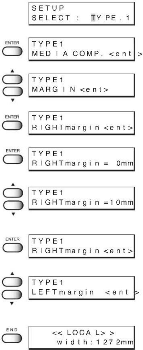
Setting [LEFTmargin]
STEPS:
- Select a type.(See page 3.3)
Here, select Type 1. - Press the [ENTER] key.
- Press the JOG keys [ ▲] and [↓ to select [MARGIN].
- Press the [ENTER] key.
- Press the JOG keys [ ▲] and [▼ to select [LEFTmargin].
- Press the [ENTER] key.
- Press the JOG keys [▲] and [↓] to set a margin.
You can set a maigin in the range -9 mm to 95 mm in mm unit. Here, set [10 mm].
-
Press the [ENTER] key.
-
Press the [END] key three times.
The menu returns to the LOCAL mode.
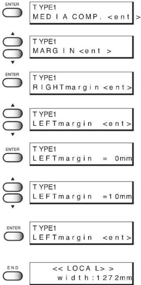

- This plotter sets the width of the printing area by detecting the position of the fabric retainer. The left and right margins can be changed by changing the position of the fabric retainer. Printing with the full width is possible by setting the fabric retainer apart from the edge of the fabric.
When using the plotter in an extremely dusty or dry place [REFRESH]
Solidification of ink can be prevented by refreshing the head during printing.
If the plotter is used in a dusty place or dry place, ink in the head will be likely to solidify. Execute the REFRESH function to enable the ink to be ejected properly from the ink head. Concerning the frequency of refreshing of the ink nozzle, select and configure from following four levels.
LEVEL 0 : Frequency of refreshing is low.
LEVEL 1 : Frequency of refreshing is normal.
LEVEL 2 : Frequency of refreshing is slightly high.
LEVEL 3 : Frequency of refreshing is high.
STEPS:
- Select a type. (See page 3.3)
Here, select [Type.1].
-
Press the [ENTER] key.
-
Press the JOG keys [ ▲] and [▼] to select [REFRESH].
-
Press the [ENTER] key.
-
Press the JOG keys [ ▲] and [▼] to set a refresh level.
There are four refresh levels from which you can select. [LEVEL0], [LEVEL1], [LEVEL2], [LEVEL3] Here, select [LEVEL2].
-
Press the [ENTER] key.
-
Press the [END] key twice.
The menu returns to the LOCAL mode.
SETUP SELECT : TYPE . 1
ENTER
TYPE1
MEDIA COMP.
TYPE1
REFRESH
ENTER TYPE1 REFRESH : LEVEL 1
TYPE 1 REFRESH : LEVEL 2
ENTER TYPE1 REFRESH
Setting a unit of length displayed on the LCD [MM/INCH]
This function sets a unit of set values displayed on the LCD.
Use this function when displaying "width" and "length" of the fabric after setting of the origin or detection of the fabric. When the plotter is shipped from the factory, the unit of display is set to MM (millimeter).
MM : Numerics are expressed in millimeters.
INCH : Numerics are expressed in inches.
STEPS:
- Select a type. (See page 3.3)
Here, select [Type.1].
-
Press the [ENTER] key.
-
Press the JOG keys [ ▲] and [▼ to select [MM/INCH].
-
Press the [ENTER] key.
-
Press the JOG keys [▲] and [▼] to set a unit of length displayed on the LCD.
Here, select [MM].
-
Press the [ENTER] key.
-
Press the [END] key twice.
The menu returns to the LOCAL mode.
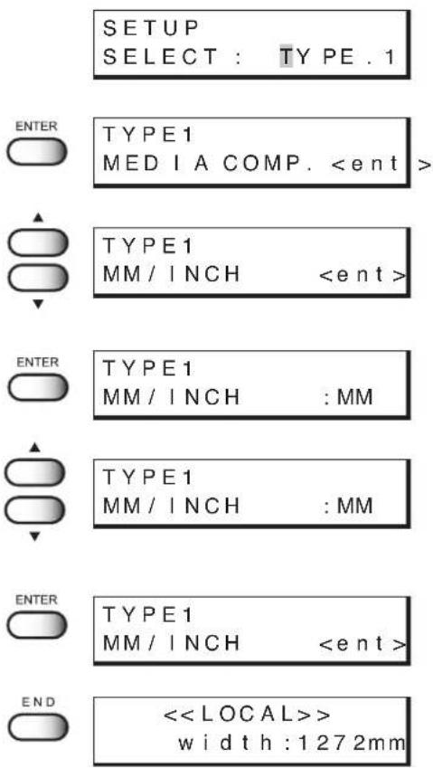
Setting the type of ink to be used [INK TYPE]
This function selects the type of ink that is to be used.
This plotter permits up to two types of ink to be loaded. When starting an actual printing operation, however, select only one type of ink to be used according to the printing data and the fabric used. This function can be used when different types of ink are loaded in the plotter. As the ink that can be specified, select from the types of ink that have been set in the ink stations.
Reac : Reactive dye ink
Acid : Acid dye ink
Disp : Disperse dye ink
NOTE!
- If the same type of ink is set in the ink stations on both sides, the type of ink cannot be set since [INK TYPE] is not displayed on the LCD.
STEPS:
- Select a type. (See page 3.3)
Here, select [Type.1].
-
Press the [ENTER] key.
-
Press the JOG keys [ ▲] and [▼ to select [INK TYPE].
-
Press the [ENTER] key.
-
Press the JOG keys [] and [] to set a type of ink to be used.
Here, select [Reac].
-
Press the [ENTER] key.
-
Press the [END] key twice.
The menu returns to the LOCAL mode.
SETUP SELECT : TYPE . 1

TYPE1
MEDIA COMP.
TYPE1
INK TYPE

TYPE1 INK TYPE :Acid
TYPE1 INK TYPE :Reac

TYPE1
INK TYPE

<
Setting up auto-cleaning function [AUTO CLEAN]
Setup the auto-cleaning function. Printing failures may be remarkable on dusty locations or locations with low temperature. Perform cleaning for each plot to prevent printing failures.
ON : The head is cleaned automatically.
OFF : The head is not cleaned automatically.
NOTE!
- W hen setting "AUTO CLEAN" ON, before starting print, remove the ink adhered around the head. (See page 4.23)
If executing cleaning without removing the ink around the head, it may cause the nozzle condition worse.
STEPS:
- Select a type. (See page 3.3)
Here, select [Type.1].
-
Press the [ENTER] key.
-
Press the JOG keys [ ▲] and [▼ to select [AUTO CLEAN].
-
Press the [ENTER] key.
-
Press the JOG keys [ ▲] and [▼ to select [ON] or [OFF] of the [AUTO CLEAN].
Here, select [ON].
-
Press the [ENTER] key.
-
Press the [END] key twice.
The menu returns to the LOCAL mode.


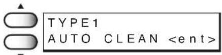

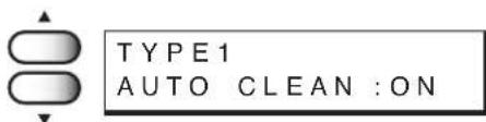


Setting up auto-cleaning function [AUTO CLEAN2]
Perform cleaning after when plotting specified length and prevent printing failures.
ON : The head is cleaned automatically after when plotting specified length.
OFF : The head is not cleaned automatically during plotting.
NOTE!
- W hen setting "AUTO CLEAN" ON, before starting print, remove the ink adhered around the head. (See page 4.23)
If executing cleaning without removing the ink around the head, it may cause the nozzle condition worse. - The fabric that stretch with exposure to water may strech while cleaning and color vary due to the misalignment when resume the printing.
In this case, change the setting to OFF, or change the cleaning type to [Soft]
STEPS:
- Select a type. (See page 3.3)
Here, select [Type.1].
-
Press the [ENTER] key.
-
Press the JOG keys [▲] and [▼] to select [AUTO CLEAN2].
-
Press the [ENTER] key.
-
Press the JOG keys [] and [] to select [ON] or [OFF] of the [AUTO CLEAN2].
Here, select [ON].
- Press the [ENTER] key.
If selecting [ON] on step 5, the cleaning type selection screen displays on LCD.
If selecting [OFF] on step 5, go to step 11.
- Press the JOG keys [] and [] to select the cleaning type.
3 types of cleaning can be selected: soft, normal, strong. Here, select [soft].
SETUP SELECT : TYPE .1

TYPE1
MEDIA COMP.
TYPE1
AUTO CLEAN2

TYPE1 AUTO CLEAN2 :OFF
TYPE1 AUTO CLEAN2 :ON

TYPE1 CLEANING : normal
TYPE1 CLEANING : soft
8. Press the [ENTER] key.
The screen to specify interval of cleaning displays on LCD.
9. Press the JOG keys [] and [] to select the length to execute the cleaning performance.
(0.1 to 10.0m in 0.1m unit)
10. Press the [ENTER] key.
11. P ress the [END] key twice.
The menu returns to the LOCAL mode.
ENTER
![Mimaki Tx2-1600 - P ress the [END] key twice. - 1](/content/2026/05/919850/images/61211b3e1ab5486e94bd81dd6702334350ea9890e8a7a71277fc5a667a34e81c.jpg)
CLEANING
I N T E R V A L = 2.5m
![Mimaki Tx2-1600 - P ress the [END] key twice. - 2](/content/2026/05/919850/images/e79860cdd9e025097a1e5baf586a52400c6ab8b4c204b7e729497acd6dba4bc7.jpg)
CLEANING
I N T E R V A L = 2.6m
![Mimaki Tx2-1600 - P ress the [END] key twice. - 3](/content/2026/05/919850/images/e571c2baec28f73caabaa32c0541fd1ad9030aae6d59ce2663844f6f2ad532ed.jpg)
TYPE1
AUTO CLEAN2
![Mimaki Tx2-1600 - P ress the [END] key twice. - 4](/content/2026/05/919850/images/9cab6379411009b26c8bd9a69b0c1f7ad6461c2967d38692727cf503ef7c8704.jpg)
<
width:1272m
Back feed Setting for End of printing [EndOf PRINT]
This function sets the operation when printing completes.
If back feed is set to ON, eliminate the waste space on media by feeding back the media.
ON : Media back feed is performed by setup value(1 to 60mm).
OFF : Media back feed is not performed.
NOTE!
- Before setting up the back feed value, confirm the distance between the data. If backfeed distance is larger than the distance between data, print is overlapped on printed data.
- When media back feed is set to ON, wrinkle may occurs on media.
STEPS:
- Select a type. (See page 3.3)
Here, select [Type.1].
-
Press the [ENTER] key.
-
Press the JOG keys [ ▲] and [▼ to select [EndOf PRINT].
-
Press the [ENTER] key.
-
Press the JOG keys [] and [] to select [ON] or [OFF] of the [BACK FEED].
Here, select [ON].
-
Press the [ENTER] key.
-
Press the JOG keys [▲] and [▼] to select the back feed distance.
select the value among 1 to 60mm
-
Press the [ENTER] key.
-
Press the [END] key twice.
The menu returns to the LOCAL mode.
SETUP SELECT : TYPE . 1
ENTER TYPE1 MEDIA COMP.
TYPE1 EndOfPrn
BACKFEED
ENTER TYPE1 EndOfPrn BACKFEED :OFF
TYPE1 EndOfPrn BACKFEED :ON
ENTER TYPE1 EndOfPrn BACKFEED =1mm
TYPE1 EndOfPrn BACKFEED =50mm
ENTER TYPE1 EndOfPrn BACKFEED
<
Continuing printing after [Ink Near End] [PRINT CONT.]
If the remaining amount of ink decreases during printing and [Ink Near End] appears, you can replace ink for each ink station and then continue printing for the next file.
ON : Even if [INKnearEND] appears, you can use only one ink station to continue printing for the next file.
OFF : When printing for the file with [Ink Near End] occurrence is completed, you need to replace ink.
NOTE!
- If different types of ink are set in the two ink stations, this function cannot be used since [PRINT CONT.] is not displayed on the LCD.
- If [Ink End] occurs during printing, printing is stopped.
STEPS:
-
Select a type. (See page 3.3)
Here, select [Type.1]. -
Press the [ENTER] key.
-
Press the JOG keys [ ▲] and [↓ to select [PRINT CONT.].
-
Press the [ENTER] key.
-
Press the JOG keys [ ▲] and [▼to select [ON] or [OFF] of the [PRINT CONT.]. Here, select [ON].
-
Press the [ENTER] key.
-
Press the [END] key twice. The menu returns to the LOCAL mode.
SETUP SELECT : TYPE . 1

TYPE1
MEDIA COMP.
TYPE1
PRINT CONT.

TYPE1 PRINT CONT. :OFF
TYPE1 PRINT CONT. :ON

TYPE1
PRINT CONT.

<
Preventing the fabric skew [CENTERING]
This function of centering prevent the media skew. Set this function when using the roll media those left or right edge are not lined up. A sensor monitors the media right edge position and move the roll media to prevent printing run off the edge.
The roll media largely miss lined-up causes wrinkle, therefore avoid using the roll media which edge miss lined-up width is ± 20mm. To use the miss lined-up roll media, be sure to re-roll up by hand to align.
ON : Enable the centering function.
OFF : Does not enable the centering.
NOTE!
- Operates according to centering sensor.
- In case Leaf is selected for the fabric used, the feeding unit is not enabled.
STEPS:
- Select a type. (See page 3.3)
Here, select [Type.1].
- Press the [ENTER] key.
- Press the JOG keys [ ▲] and [▼ to select [CENTERING].
- Press the [ENTER] key.
- Press the JOG keys [▲] and [▼ to select [ON] or [OFF] of the [CENTERING].
Here, select [ON].
- Press the [ENTER] key.
- Press the [END] key twice.
The menu returns to the LOCAL mode.
SETUP
SELECT : TYPE.1

TYPE1
MEDIA COMP. <ent
TYPE1
CENTERING

TYPE1
C EN TE R ING :OFF
TYPE1
CENTERING :ON

TYPE1
CENTERING

<
width:1272mm
Enabling the take-up unit [TAKE-UP]
This function enables the take-up unit.
INTERVAL : Take-up operation is performed according to the slack sensor.
When Interval is selected, wrinkles at platen are less occurs and printing is stable.
On the other hand, take-up is not well performed, because take-up thickness at right and left side differs, so that take-up of roll may not complete.
ON : Take-up operation is performed with taking up the fabric continuously instead of using the slack sensor.
Wrinkes at platen tend to occur. Adjustment of torque limitter intensity is frequently required.
OFF : Does not enable the take-up unit.
NOTE!
- Operates according to slack and limit sensor.
- In case Leaf is selected for the fabric used, the take-up unit is not enabled.
STEPS:
- Select a type. (See page 3.3)
Here, select [Type.1]. - Press the [ENTER] key.
- Press the JOG keys [ ▲] and [▼ to select [TAKE-UP].
- Press the [ENTER] key.
- Press the JOG keys [▲] and [▼] to select [INTERVAL], [ON] or [OFF] of the [TAKE-UP].
Here, select [ON].
- Press the [ENTER] key.
- Press the [END] key twice.
The menu returns to the LOCAL mode.
SETUP SELECT : TYPE . 1

TYPE1
MEDIA COMP.
TYPE1
TAKE -UP

TYPE1 TAKE -UP :OFF
TYPE1 TAKE -UP :ON

TYPE1
TAKE -UP

<
Resetting printing conditions by type [SETUP RESET]
This function resets the current printing conditions to the factory-set printing conditions.
Execute this function for each of the types of set printing conditions.
STEPS:
- Select a type. (See page 3.3)
Here, select [Type.1].
-
Press the [ENTER] key.
-
Press the JOG keys [ ▲] and [▼ to select [SETUP RESET].
-
Press the [ENTER] key.
-
Press the [ENTER] key.
The current printing conditions are reset to the factory-set printing conditions.
- Press the [END] key twice.
The menu returns to the LOCAL mode.
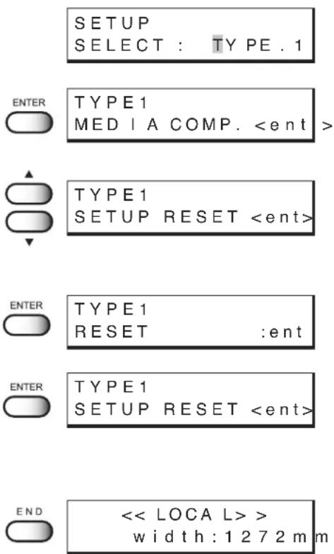
SETUP SELECT : TYPE . 1
TYPE1
MEDIA COMP.
Chapter 4
Maintenance functions
In order to keep the printer in good operating condition, it is necessary to carry out maintenance of the printer periodically.
This chapter describes the functions that help solve the problem of deterioration in image quality and replace a waste ink tank.
The printer needs maintenance when it is left out of operation for a long period of time.
Table of contents
Maintenance of the printer 4.2
Before starting maintenance 4.3
Maintenance functions 4.4
Maintenance of the printer
The term “maintenance” as used herein refers to the operation that has to be performed to keep the printer in good operating condition.
Tocarry out maintenance of the printer, select [MAINTENANCE] from the function menu and make the necessary settings.
Function menu [MAINTENANCE]
The table, below, shows the tree structure of the function menu [MAINTENANCE].
In order to use the application functions of the printer, it is necessary to understand the proper sequence of key operations.
![Mimaki Tx2-1600 - Function menu [MAINTENANCE] - 1](/content/2026/05/919850/images/afd86b7fdc5f81ac550f65e0c410c28c7553cb53bb2b01d8a1fa734a01c506a7.jpg)
flowchart
graph TD
    A["[FUNCTION"] SET UP] --> B["See Chapter 2 "How to use the basic functions.""]
    C["[FUNCTION"] MAINTENANCE] --> D["LIST"]
    D --> E["DATA DUMP"]
    E --> F["PRINT adjust —— PRINT START —— PATTERN 1 to 7 —— Adjust value: -15 to 15"]
    F --> G["STATION CARRIAGEout, WIPER EXCHG, NOZZLE WASH, DRAIN WASH, STRAGE WSH"]
    G --> H["CARRIAGE CARRIAGEout"]
    H --> I["HEAD HEIGHT"]
    I --> J["FILL UP INK Select Head Loading operation"]
    J --> K["INK CHANGE Reac, Acid, Disp"]
    K --> L["USE HEAD —— ALL, FRONT, REAR (Displayed at the time of setting for 1-way high-speed printing.)"]
    L --> M["STRETCH CHECK —— PATTERN —— 50%, 100%, 200%, 300%"]
    M --> N["PASS 4-pass, 8-pass"]
    N --> O["COLOR 1A, 2B, 3C, 4D, 5E, 6F, 7G, 8H"]
    M --> P["INFORMATION —— VERSION"]
    P --> Q["SERIAL NO."]
    Q --> R["[FUNCTION"] DISPLAY]
    R --> S["See Chapter 2 "How to use the basic functions.""]
Before starting maintenance
Checking the menu mode
Before executing any of the maintenance functions, check the menu mode.
The menu mode must be the LOCAL mode or the FUNCTION mode before maintenance can be started.
Make sure that either <
Invoking a maintenance function
In order to execute any of the maintenance functions, it is necessary to perform the following operation on the operation panel.
You have to understand how to invoke the desired maintenance function to carry out maintenance.
STEPS:
1. Make sure the mode is LOCAL mode.
Press the [REMOTE] key and put the menu back into the LOCAL mode.
When the menu mode is the FUNCTION mode, simply proceed to Step 2.

2. Press the [FUNCTION] key.
![Mimaki Tx2-1600 - Press the [FUNCTION] key. - 1](/content/2026/05/919850/images/722cd826b586b971bfcd2a7b31e34da6482a14773c03f59ce40db61148ccd5fb.jpg)
![Mimaki Tx2-1600 - Press the [FUNCTION] key. - 2](/content/2026/05/919850/images/a5ca7edea3ed99652c98c9b2a41ab019123e008649e209c3be8e01a9687ec98b.jpg)
3. Press the JOG keys [ ▲] and [▼ to select [MAINTENANCE].
![Mimaki Tx2-1600 - Press the JOG keys [ ▲] and [▼ to select [MAINTENANCE]. - 1](/content/2026/05/919850/images/0d22df961d11ad8908617d110978789fe59edfcff424a9f22b6207b16c7aa7b9.jpg)
![Mimaki Tx2-1600 - Press the JOG keys [ ▲] and [▼ to select [MAINTENANCE]. - 2](/content/2026/05/919850/images/f7c13ae7a3158026c983f7d5b642b34635ef1024d71f20e48bd14885e11ed695.jpg)
4. Press the [ENTER] key.
![Mimaki Tx2-1600 - Press the [ENTER] key. - 1](/content/2026/05/919850/images/e349ec1c36daa92dc9b71367b6c914100dfcf64f351b119894b3d4cb6e64554e.jpg)
![Mimaki Tx2-1600 - Press the [ENTER] key. - 2](/content/2026/05/919850/images/37645226561228f232e1d12676d3a7da89dcbf9916da48553ca5c8f302148879.jpg)
5. Select the next operation.
Set up the desired maintenance function to carry out maintenance. (See page 4.4 through 4.32)
Maintenance functions
Press the [FUNCTION] key and set up the desired maintenance function.
Drawing setup conditions [LIST]
This function outputs the current settings of the printer.
They are useful in carrying out maintenance of the printer.
Explanation of the list
- SETUP : Indicates a value that is specified with the FUNCTION.
- PRINTadjust : Indicates a correction value for dot position.
- REPLACE COUNTER : Indicates the number of times the ink cartridges are replaced.
- VERSION : Indicates the version of the firmware and memory capacity of the device.
- PARAMETER : Used for service persons for maintenance.
STEPS:
1. Select [LIST] from [MAINTENANCE].
(See page 4.3)
2. Press the [ENTER] key.
Printing the LIST is started.
| LIST (System Ver2.01) (I/F Ver1.50) | ||||||||
| (1) SETUP | TYPE1 | TYPE2 | TYPE3 | < TYPE4 > | ||||
| MEDIA COMP. | 600 | :HOST | -500 | :PLOT | -1 | :PLOT | 0 | :HOST |
| PRINT MODE | STD | :PLOT | FINE | :HOST | HIGHspd | :PLOT | STD | :HOST |
| DIRECTION | :BI-D | :UNI-D | :BI-D | :UNI-D | ||||
| RET.SPD UP | OFF | ON | OFF | ON | ||||
| INK LAYERS | 9 | :HOST | 6 | :PLOT | 3 | :PLOT | 1 | :HOST |
| DRYING TIME | 9.9s | :PLOT | 5.0s | :HOST | 1.1s | :PLOT | 0.0s | :HOST |
| RIGHTmargin | -9mm | -1mm | 95mm | 0mm | ||||
| LEFTmargin | 95mm | -9mm | -1mm | 0mm | ||||
| REFRESH | LEVEL0 | :PLOT | LEVEL1 | :HOST | LEVEL2 | :PLOT | LEVEL3 | :HOST |
| MM/INCH | INCH | MM | INCH | MM | ||||
| INK TYPE | Reac | :HOST | Acid | :PLOT | Reac | :PLOT | Reac | :HOST |
| AUTO CLEAN | ON | OFF | ON | OFF | ||||
| AUTO CLEAN2 | OFF | ON | ON | OFF | ||||
| CENTERING | OFF | ON | OFF | ON | ||||
| TAKE-UP | OFF | ON | INTERVAL | ON | ||||
| (2) DISPLAY | ENGLISH | |||||||
| (3) PRINTadjust | PATTERN1 | PATTERN2 | PATTERN3 | PATTERN4 | ||||
| 0.0 | 0.0 | 0.0 | 0.0 | |||||
| PATTERN5 | PATTERN6 | PATTERN7 | ||||||
| 0.0 | 0.0 | 0.0 | ||||||
| (4) REPLACE CNT | ||||||||
| Cartridge | E: 8 | |||||||
| Ink Level | 1: 30% | 2: 2% | 3: 57% | 4: 57% | 5: 57% | 6: 98% | 7: 2% | 8: 57% |
| 9: 57% | 10:7% | 11:57% | 12:57% | 13:57% | 14:2% | 15:57% | 16:57% | |
| INK IC ERROR | 1: 0 | 2: 0 | 3: 0 | 4: 1 | 5: 0 | 6: 0 | 7: 0 | 8: 0 |
| 9: 0 | 10:0 | 11:0 | 12:0 | 13:0 | 14:0 | 15:0 | 16:0 | |
| INK TYPE | F:Acid | R:Reac | ||||||
| SCAN COUNT | 0 | (×1000) | ||||||
Printing HEX code of printing command [DATA DUMP]
This function prints data commands received from the computer, in HEX code.
The HEX code is an alphanumeric representation of printing commands.
By using this code, it is possible to check if there are any abnormal data commands.
NOTE!
- When this function is used to output data commands on a sheet of paper, use A4 or larger size with the long side set horizontally.

• DATA DUMP automatically feeds line according to the size of paper used.
STEPS:
1. Select [DATA DUMP] from [MAINTENANCE].
(See page 4.3)
MAINTENANCE
DATA DUMP
2. Press the [ENTER] key.
Transfer data from the host computer and drawing the DATA DUMP is started.
![Mimaki Tx2-1600 - Press the [ENTER] key. - 1](/content/2026/05/919850/images/cab54ce11d3656bb6216d9f2afca9fb65acf9521650abcf33c414b1004815d0d.jpg)
MAINTENANCE
* * DATA DUMP * *
3. When printing is completed, press the [REMOTE] key.
![Mimaki Tx2-1600 - When printing is completed, press the [REMOTE] key. - 1](/content/2026/05/919850/images/e727a971522974cfef3e05e00167343796d05839b564915a741aa77ac1e3968e.jpg)
![Mimaki Tx2-1600 - When printing is completed, press the [REMOTE] key. - 2](/content/2026/05/919850/images/96b383561b8d00a9b40f2dbb37c3d9c97333af748204f8519d003cf0c4d0a5c2.jpg)
4. Press the [DATA CLEAR] key.
![Mimaki Tx2-1600 - Press the [DATA CLEAR] key. - 1](/content/2026/05/919850/images/c72ce56781339d1423370be529f1a456697577d2514ee5406e24bd494af62f7c.jpg)
![Mimaki Tx2-1600 - Press the [DATA CLEAR] key. - 2](/content/2026/05/919850/images/fdea304a8f696d190f51cf4a21443ea57b3b13471bff6cf3827341b0d9711f92.jpg)
5. Press the [ENTER] key.
Correcting the dot positions after adjusting the head height [PRINTadjust]
When the head height is adjusted, be sure to correct the dot positions.
Since the adjustment of head height is done by hand, the head will slightly deviate from the correct position (See page 1.39). This function corrects the dot positions to ensure that the accurate printing result is obtained.
The dot positions are corrected by comparing the ink dropping positions on each of the seven test patterns between the two printing directions.
STEPS:
1. Select [PRINTadjust] from [MAINTENANCE].
(See page 4.3)
![Mimaki Tx2-1600 - Select [PRINTadjust] from [MAINTENANCE]. - 1](/content/2026/05/919850/images/22ddb7a6a197369e4c30383f4a15d8e7cce46d6462b2f2e2dc894d66932ba476.jpg)
2. Press the [ENTER] key.
![Mimaki Tx2-1600 - Press the [ENTER] key. - 1](/content/2026/05/919850/images/51db14c115fd312615dc44405ac46d078b6c5a91450374c140a049468e36faf0.jpg)
3. Press the [ENTER] key.
![Mimaki Tx2-1600 - Press the [ENTER] key. - 1](/content/2026/05/919850/images/88edd2564b42bd413f8a8079ae17d0a7a825b5a72b87d53394a2b56189908fba.jpg)
Printing of the test patterns for the correction of dot position starts. There are seven types of test patterns that are printed.
4. Press the JOG keys [] and [] to correct the dot position of pattern 1.
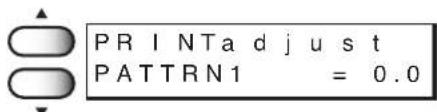
The seven test patterns that are output are sequentially named [Pattern 1], [Pattern 2], [Pattern 3], and [Pattern 4].
Select the correct dot positions on Pattern 1 using the JOG keys [▲] and [▼].
Select the dot positions that make a straight line on the test pattern in the two printing directions.
Select the dot positions 4.0
that make a straight line on
the test pattern in the two plotting direction
![NOTE! • If the pattern correction value for straight lines is not within -15 through +15, adjust the head height and then correct it again with [PRINTadjust].](/content/2026/05/919850/images/9150d3c58625c042cbdecc3e41e42b792b5f5a92fbd62e64c4177f9516f9c14e.jpg)
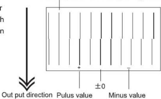
5. Press the [ENTER] key.
![Mimaki Tx2-1600 - Press the [ENTER] key. - 1](/content/2026/05/919850/images/a0104e3990f6a8b25b8280d4e7095bd37eb2857ef795baa55c55818c0d42d91f.jpg)
6. Repeat Steps 4 and 5 to correct the dot positions on Patterns 2 to 7.
Select the correct dot positions on each of the patterns.
PRINTa d j u s t
PATTRN2 = 0.0
PRINTa d j u s t
PATTRN3 = 0.0
PRINTa d j u s t
PATTRN4 = 0.0
PRINTa d j u s t
PATTRN5 = 0.0
PRINTa d j u s t
PATTRN6 = 0.0
PRINTa d j u s t
PATTRN7 = 0.0
When pressing the [ENTER] key after setting the correction on pattern 7, the right indication is shown.
MA INTENANCE
PRINTa d jus t<ent>
7. Press the [END] key twice.
The menu returns to the LOCAL mode.
![Mimaki Tx2-1600 - Press the [END] key twice. - 1](/content/2026/05/919850/images/78ffd935794984602743b58e881698adb45ea37472537dd7a70201bf3adb063e.jpg)
Moving the carriage to clean the station interior [CARRIAGEout]
This function moves the carriage for maintenance of the ink station.
The interior of the station needs maintenance when a blurred test pattern is not corrected even after the cleaning function (page 2.12) is executed or when a consumable part is to be replaced. Frequently wipe the capping station clean to eliminate dust and paper chips. Wiping with a fluffy wiper only rubs dust over the capping station. Replace the fluffy wiper immediately with a new one. (page 4.11)
NOTE!
- D o not move the carriage out of the capping station by hand.
Use the appropriate operation key to move the carriage.
- Before performing [STATION], be sure to move down the clamp lever on the front side of this printer.
STEPS:
-
Move down the clamp lever on the front face of the printer.
-
Select [STATION] from [MAINTENANCE].
(See page 4.3)
-
Press the [ENTER] key.
-
Press the [ENTER] key.
The carriage is moved from the maintenance station.
- Open the maintenance cover, then perform the following maintenance works for the station interior.
The following maintenance should be executed:
- Cleaning the ink cap (See page 4.9)
Clean the surfaces around the ink caps in the station.
- Cleaning or replacing the wiper (See page 4.11-13)
Clean or replace the wiper.

- When the message "Replace Wiper" is displayed on the LCD, replace the wiper.




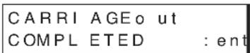
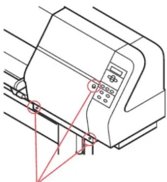
natural_image
Technical line drawing of a printer or printer with control panel and mounting bracket (no text or symbols)Remove these screws
- Close the maintenance cover, then press the [ENTER] key.
INTIALIZING PLEASE WAIT
<
If a defective printing is not corrected even after the cleaning function is executed
Cleaning the ink caps
Clean the ink caps if a defective printing is not corrected or nozzles are clogged even after the cleaning function is executed or when the printer is left unused for a long period of time.
STEPS:
- Execute the station maintenance [CARRIAGEout] to move the carriage.
(See the steps 1 to 4 on page 4.8)
STATION MAINT MAINT : CARRIAGE out
-
Open the maintenance cover.
-
Remove stains with a swab from the rubber mounted around the cap.
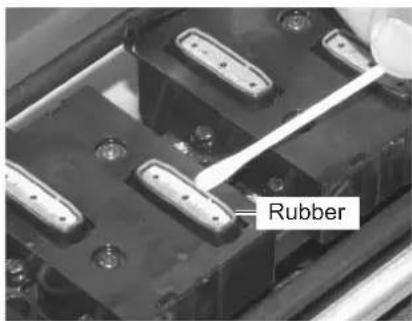
- Close the maintenance cover, then press the [ENTER] key.
INTIALIZING PLEASE WAIT
<
Periodical cleaning of the wiper
Cleaning the wiper
The wipers are provided for cleaning the heads. As the printer is used to print images, the wipers gradually become stained with ink and dust. Clean stained wipers.
The wiper is separately available from your local distributor or our office.
Notes on handling the wipers
NOTE!
- A void contacting the rubber portion of the new wiper. Contacting it will result in clogged nozzle.
• C lean the two wipers at a time.
- The front side of each wiper is made of felt, and the rear side is made of rubber. Do not rub the felt side with a swab. Instead, press the swab against the felt side surface to remove dirt. Rubbing the felt side surface will make it fluffy and result in clogged nozzle. Wipe ink off the rubber side surface with a swab.
- When executing this function, the carriage will come out of the capping station. If the carriage is left in the aforementioned state for an extended period of time, the nozzles can be clogged. Once the replacement of the wiper and the cleaning of the caps have been completed, immediately press the [ENTER] key to allow the carriage to return to the capping station.
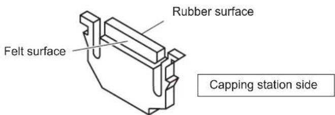
STEPS:
- Execute the station maintenance [CARRIAGEout] to move the carriage.
(See the steps 1 to 4 on page 4.8)
-
Open the maintenance cover.
-
Clean up the wiper as described below.
-
Close the maintenance cover, then press the [ENTER] key.
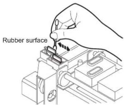
When the message [Replace Wiper] is displayed [WIPER EXCHG]
The wipers are consumable parts. As the wiper continues cleaning the head, it gets stained with ink and dust. The printer counts the number of times the wipers are cleaned and tells when to replace them. When the message [Replace Wiper] is displayed, replace the wiper with a new one without delay. When replacing the wiper, remove ink adhered at the bottom surface of the slider.
The message [Replace Wiper] is displayed while the printer is in operation or when the printer power is switched on. When the message is displayed, replace the wipers with new ones.
Wiper Replace Wiper
![Mimaki Tx2-1600 - When the message [Replace Wiper] is displayed [WIPER EXCHG] - 1](/content/2026/05/919850/images/67c4adb098e321894c215454181ddb6f88cc16e05e4fa1409f57f6cb6b4636fd.jpg)
- The wiper is separately available from your local distributor or our office.
NOTE!
- Do not press the [ENTER] key other than the case of replacing wipers. The number of wiper operations that is counted in the printer will be reset. Do not select [Replace Wiper] unless the wiper is to be really changed.
STEPS:
- Select [STATION] from [MAINTENANCE].
(See page 4.3)
-
Press the [ENTER] key.
-
Press the JOG keys [ ▲] and [▼ to select [WIPER EXCHG].
-
Press the [ENTER] key.
The carrige will come out of the capping station.
-
Open the maintenance cover to change the wiper.
-
Holding the projections at both ends, draw out the wiper.
Use the gloves that are supplied with the separately-available cleaning wiper to protect your hands from stains.
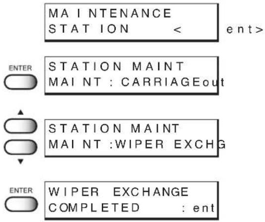
flowchart
graph TD
    A["MAINTENANCE STATION < ent>"] --> B["STATION MAINT MAINT : CARRIAGEout"]
    B --> C["STATION MAINT MAINT :WIPER EXCHG"]
    C --> D["WIPER EXCHANGE COMPLETED : ent"]
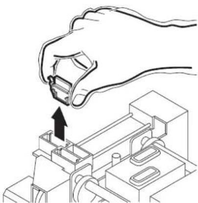
natural_image
Line drawing of a hand inserting a cable into an electronic component (no text or symbols)7. Holding the projections at both ends, insert a new wiper into place.
NOTE!
- D o not touch the rubber portion of a new wiper. It can cause the nozzle to be clogged. - Insert the wiper so that its felt side surface is placed on the left as viewed from your position.
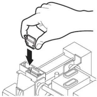
natural_image
Line drawing of a hand inserting a small component into an electronic device (no text or symbols)8. Clean the wiper guide shaft using a swab or cloth.
(If dirt is hard to remove, use a swab of cloth damepened with water.)
NOTE!
- Extremely dirty wiper guide shaft may cause operation failure of the wiper, resulting in error display.
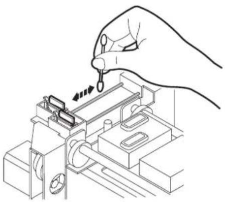
natural_image
Line drawing of a hand using a tool to adjust or install electronic components (no text or symbols visible)9. Close the maintenance cover, then press the [ENTER] key.
INTIALIZING PLEASE WAIT
<
When the message [Clean Wiper Shaft] is displayed
The message shown on the right is displayed after several numbers of wiping.
Please clean the wiper shaft at once if this message is displayed.
![Mimaki Tx2-1600 - When the message [Clean Wiper Shaft] is displayed - 1](/content/2026/05/919850/images/fa0089a4648b9ed5e3218894182452649a9aa1705d352794b35c7528206d0684.jpg)
Extremely dirty wiper shaft may cause wiper malfunction and resulting an error display. The wiper is functioning only during the head cleaning, and the number of wiping vary according to the cleaning type.
NOTE!
- When exchanging the wiper, please clean the wiper shaft too.
STEPS:
- Select [STATION] from [MAINTENANCE].
(See page 4.3)

- Press the [ENTER] key.

- Press the [ENTER] key.
The carrige will come out of the capping station.

-
Open the maintenance cover.
-
Clean the wiper guide shaft using a swab or cloth.
(If dirt is hard to remove, use a swab of cloth damepened with cleaning liquid.)
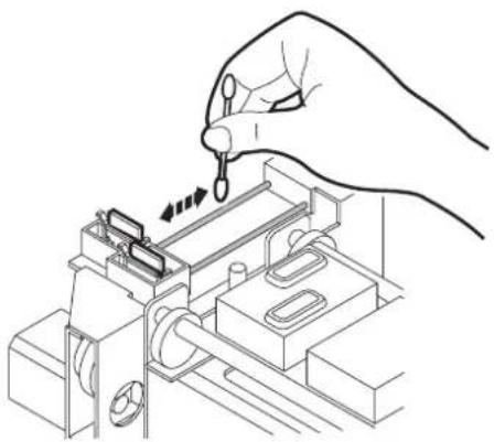
natural_image
Line drawing of a hand using a tool to adjust or install electronic components (no text or symbols visible)- Close the maintenance cover, then press the [ENTER] key.

Clean up the nozzle as for nozzle clogging.
If nozzle clogging cannot be resolved even after cleaning several times, execute the [FILL UP INK] function. (Page 4.25)
If this error cannot be resolved with these functions, contact the dealer.
NOTE!
- T wo colors (two cartridges) per head are used. If the remaining amount of one ink is extremely greater than another ink's amount, it may flow into the cartridge which has lesser ink to make their ink-head even.
Execute the [FILL UP INK] function (Page 4.25) if the inks are mixed.
- Operate it in the head only with the nozzle clogging.
Cleaning Tools :
- Cleaning liquid bottle kit A29 (SPC-0137 : Option)
- Syringe
STEPS:
- Select [STATION] from [MAINTENANCE].
(See page 4.3)
- Press the [ENTER] key.
ENTER
STATION MAINT
MAINT: CARRI AGEout
- Press the JOG keys [ ▲] and [▼to select [NOZZLE CLN].

STATION MAINT
MAINT: NOZZLE CLN
- Press the [ENTER] key.
Attention about the ink mixing is displayed.
ENTER
Color May Mix Up
Continue OK? : ent
- Press the [ENTER] key.
The carrige will come out of the capping station.
ENTER
WIPER CLEANING
COMPLETED : ent
- Open the maintenance cover.
Remove these screws
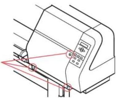
natural_image
Technical line drawing of a printer or printer with control panel and paperclip (no text or symbols)7. Clean the wiper.
Use and push a swab contained cleaning liquid to take off some dust on the felt surface.
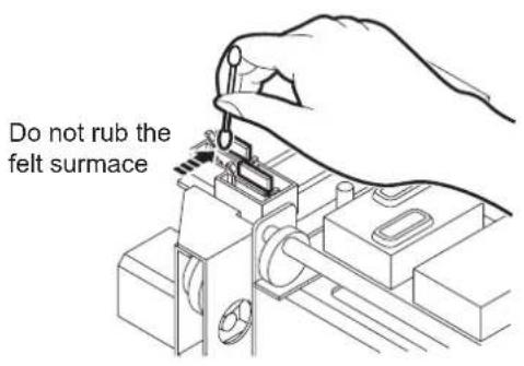
Use a swab contained cleaning liquid to take off some inks on the rubber surface.
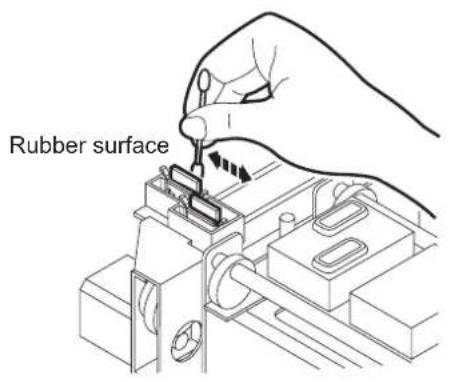
- Clean the wiper and press the [ENTER] key.

FILL UP WASHINGS COMPLETED : ent
- Fill the cap with the cleaning liquid using a syringe.
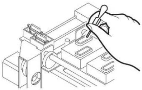
natural_image
Line drawing of a hand using a tool to adjust or install electronic components (no text or symbols visible)-
Close the maintenance cover.
-
press the [ENTER] key.

NOZZLE CLEANING
WAIT TIMER = 1min
- Press the JOG keys [▲] and [▼] to select the time to leave. (1-99 minutes: 1 min unit)
NOZZLE CLEANING
WAIT TIMER = 10min
- Press the [ENTER] key.
The initial operation is performed.

INTIALIZING
PLEASE WAIT
Remaining time is displayed.
WATING
0 0 : * * : * *
After remaining time is over, execute cleaning.
It displays the remaining cleaning time.
CLEANING
0 0 : * * : * *
Cleaning is completed, the menu returns the LOCAL mode.
<
Ink discharge way cleaning [DRAIN WASH]
The ink discharge way may become clogged by coagulated ink. It must be cleaned at regular intervals to avoid clogging.
Ink discharge way: Tubing between the cap and the waste ink tank
![Mimaki Tx2-1600 - Ink discharge way cleaning [DRAIN WASH] - 1](/content/2026/05/919850/images/efbee5d971be25a16949e43075a7a742779c54f85aebda050e94b69ea13af93c.jpg)
- D o not move the carriage out of the capping station by hand. Use the appropriate operation key to move the carriage.
Cleaning Tools :
- Cleaning liquid bottle kit A29 (SPC-0137 : Option)
- Syringe
STEPS:
- Select [STATION] from [MAINTENANCE]. (See page 4.3)

- Press the [ENTER] key.

- Press the JOG keys [ ▲] and [▼] to select [DRAIN WASH].
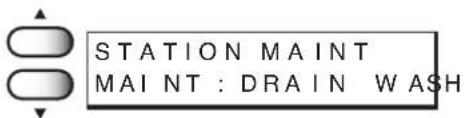
- Press the [ENTER] key.

The table moves backward, the Y-bar moves to the top, the wiper moves forward, and the carriage moves on the table. Dry suction starts in cycles consisting of 10 seconds of suction followed by 10 seconds of pause.
- Open the maintenance cover.
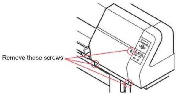
- Remove the cleaning liquid with a syringe. During the suction pause period, drop the cleaning liquid until just before it overflows from the cap.
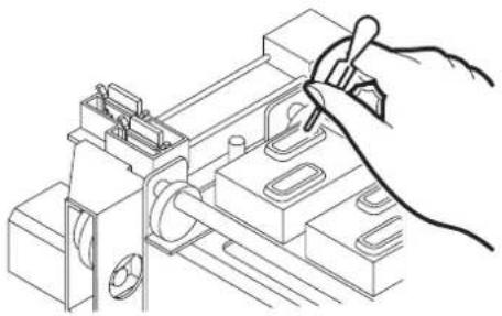
natural_image
Line drawing of a hand using a tool to adjust or install electronic components (no text or symbols visible)-
Close the maintenance cover.
-
Press the [ENTER] key.
Dry suction continues for 30 seconds and the initial operation is performed..
The menu return to the LOCAL mode.

INTIALIZING PLEASE WAIT
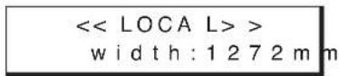
When not in use the machine over the long term [STORAGE WSH]
When not in use the machine over a week, perform [STRAGE WSH] function to clean the head nozzle and ink discharge way.
After performing the function, store the machine.
NOTE!
- T wo colors (two cartridges) per head are used. If the remaining amount of one ink is extremely greater than another ink's amount, it may flow into the cartridge which has lesser ink to make their ink-head even.
Execute the [FILL UP INK] function (page 4.25) if the inks are mixed.
Cleaning Tools :
- Cleaning liquid bottle kit (SPC-0137 : Option)
- Syringe
STEPS:
- Select [STATION] from [MAINTENANCE].
(See page 4.3)
- Press the [ENTER] key.

STATION MAINT MAINT: CARRIAGE out
- Press the JOG keys [ ▲] and [▼] to select [STORAGE WSH].
STATION MA INT MAINT: STORAGE WSH
- Press the [ENTER] key.
Attention about the ink mixing is displayed.

Color May Mix Up Continue OK? : ent
- Press the [ENTER] key.
The carrige will come out of the capping station.

WIPER CLEANING COMPLETED : ent
- Open the maintenance cover.
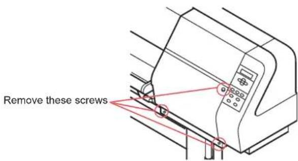
7. Holding the projections at both ends, draw out the wiper.
Use the gloves that are supplied with the separately-available cleaning wiper to protect your hands from stains.
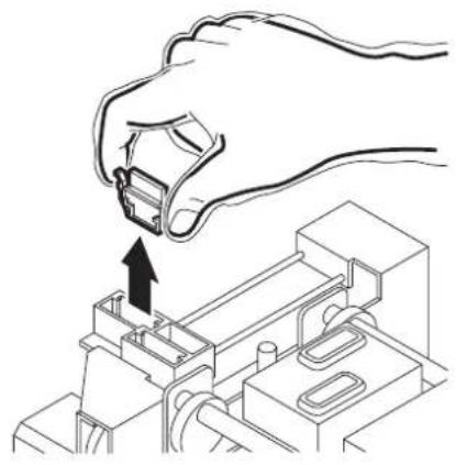
natural_image
Line drawing of a hand inserting a connector into an electronic device (no text or symbols)8. Use a swab soaked with the cleaning liquid to clean off ink blots on wiper and bracket.

- If dirt of curl is serious, replace the wiper with a new one. At the time of replacement, be sure to terminate the machine operation and follow the wiper replacement procedure.
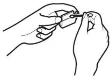
natural_image
Line drawing of hands using a tool to draw or apply a small object (no text or symbols present)9. Holding the projections at both ends, insert a clean wiper into place.
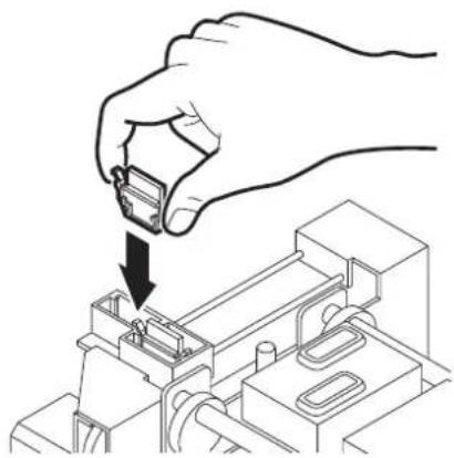
natural_image
Hand inserting a small electronic component into an electrical circuit board (no text or symbols visible)10. Press the [ENTER] key.
![Mimaki Tx2-1600 - Press the [ENTER] key. - 1](/content/2026/05/919850/images/7716426475a654d1eb722d998c6c3be6a83ef0773faa34b5b99e169fc7081ad5.jpg)
FILL UP WASHINGS COMPLETED :ent
11. F ill the cap with the cleaning liquid using a syringe.
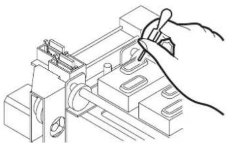
natural_image
Line drawing of a hand using a tool to adjust or install electronic components (no text or symbols visible)-
Close the maintenance cover.
-
Press the [ENTER] key.
-
Press the JOG keys [▲] and [▼] to select the time to leave. (1-99 minutes: 1 min unit)
Normally set 1 min.
- Press the [ENTER] key.
The initial operation is performed.
Remaining time is displayed.
After remaining time is over, execute cleaning. Remaining cleaning time is displayed.
After cleaning the nozzles, the Y-bar moves to the top. The wiper moves toward you and the carriage moves away from the station.

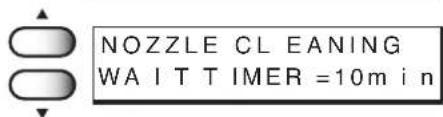

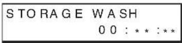
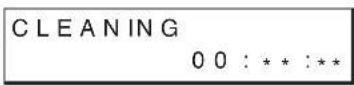
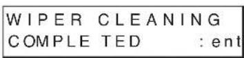
-
Open the maintenance cover.
-
Clean the wiper.
Use and push a swab contained cleaning liquid to take off some dust on the felt surface.
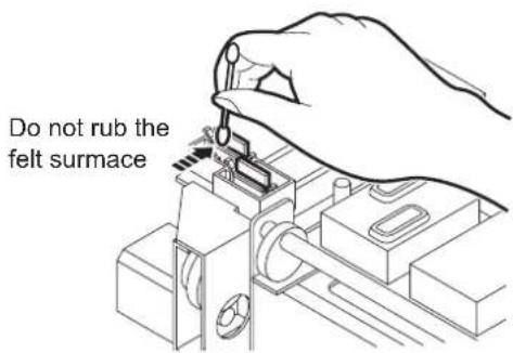
Use a swab contained cleaning liquid to take off some inks on the rubber surface.
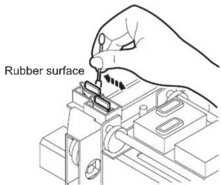
- Clean the wiper and press the [ENTER] key.

- Fill the cap with the cleaning liquid using a syringe.
Dry suction starts in cycles consisting of 10 seconds of suction followed by 10 seconds of pause.
Repeat the performance of the air aspiration several times to clean up the ink discharge way.
Perform the operation for the each cap.
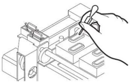
natural_image
Line drawing of a hand using a pen to adjust or install electronic components (no text or symbols visible)- Close the station cover, and press the [ENTER] key.
Carrige returns the station to the initial operation performed.

The menu return to the LOCAL mode.
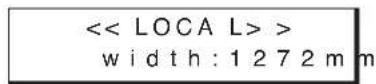
Move the carriage to the left maintenance station [CARRIAGE]
This function moves the carriage to the left maintenance station to chack the head, to clean the nozzle surface and to do maintenance of carriage.
STEPS:
- Select [CARRIAGE] from [MAINTENANCE]. (See page 4.3)
- Press the [ENTER] key.
- Press the [ENTER] key. The carriage is moved to the left maintenance station.
- Remove the left maintenance cover.
Lossen the 3 screws attached at the bottom of the main unit and remove 1 screw on the left maintenance cover and then remove the left maintenance cover.
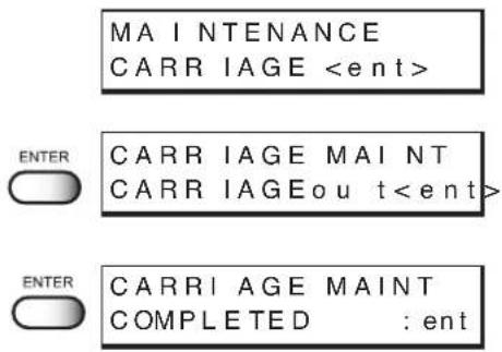
- Do the maintenance of the carriage.
Using the supplied swab with cleaning liquid, remove ink around the head.

- Never rub the surface of the nozzle, as this may cause discharge failure.

- Use the cleaning liquid (SPC-0137:optional item).
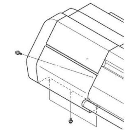
natural_image
Technical line drawing of a mechanical component with no visible text or symbols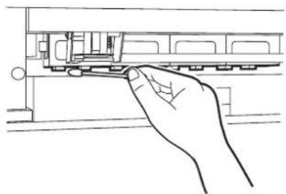
natural_image
Line drawing of a hand inserting a component into a device (no text or symbols)6. Close the left maintenance cover, then press the [ENTER] key.
![Mimaki Tx2-1600 - Close the left maintenance cover, then press the [ENTER] key. - 1](/content/2026/05/919850/images/093e04beb5f1b3ccc724e54b82c0c035311f5ed498cceb63f646b362634d366a.jpg)
INTIALIZING
PLEASE WAIT
![Mimaki Tx2-1600 - Close the left maintenance cover, then press the [ENTER] key. - 2](/content/2026/05/919850/images/e3e1c57e18a128565f3e4c8b2b626bebc3c6b0779de3b48303870364fe2d6376.jpg)
- In the case where a fabric is loaded on the printer, the fabric detection display will appear on the LCD after the initialization.
Adjusting the head height when the fabric used is changed [HEAD HEIGHT]
For the procedure of adjusting the head height, See page 1-36.
NOTE!
- Before adjusting the head height, be sure to remove the fabric from the platen. If an attempt is made to adjust the head height with the fabric kept set on the platen, the fabric gets caught on the carriage during “carriage out” operation, causing damage to the head.
Menu displayed after the ink cartridge is installed [FILL UP INK]
When the ink cartridge is replaced with a new one or a new ink cartridge is installed, the printer charges ink automatically. Therefore, a menu for charging ink is included in the maintenance functions. Normally, however, this function is not used.
STEPS:
1. Select [FILL UP INK] from [MAINTENANCE].
(See page 4.3)
2. Press the [ENTER] key.
3. Press the JOG keys [ ▲] [▼] [ ]▶ to select the head to be filled up.
Each time a JOG key is pressed, the row of heads to be cleaned changes from R to F (or F to R). The upper eight of test printing indicates the R row of heads, and the lower eight indicates the F row of heads.
4 types of head row can be selected: [1234], [5678], [ABCD], and [EFGH].
4. Press the [ENTER] key.
Ink filling up is started.
Remaining time for ink filling up is displayed on the second line of LCD.
After completing the performance, the LCD shown on the right is displayed.
5. Press the [END] key twice.
When charging ink different from the one in use [INK CHANGE]
The INK CHANGE function charges ink different from the one currently in use. When the same type of ink as is set in the ink station is to be used, it is unnecessary to execute this function.
NOTE!
- Be sure to use the inks and ink cartridges specified by MIMAKI. Please be noted that MIMAKI ENGINEERING CO., LTD. shall have no liability for any trouble that arises when using any ink cartridge or ink other than the genuine MIMAKI brand ones.
- An additional head cleaning cartridge is required for ink replacement.
STEPS:
1. Select [INK CHANGE] from [MAINTENANCE].
(See page 4.3)
2. Press the [ENTER] key.
The ink type currently filled in the ink station is shown.
3. Press the JOG keys [] and [] to set the type of ink to be filled in the R-row ink station.
[Acid] : Acid dye ink
[Reac] : Reactive dye ink
[Disp] : Disperse ink
4. Press the JOG key []to move the cursor.
5. Press the JOG keys [▲] and [▼] to set the type of ink to be filled in the F-row ink station.
6. Press the [ENTER] key.
7. Press the [ENTER] key.
MAINTENANCE
INK CHANGE
ENTER In k Set R: Acid F: Acid
Ink Set R:Reac F:Acid
Ink Set R:Reac F:Acid
In k Set R:Reac F:Ac id
ENTER INK CHANGE START :ent
ENTER WASH REMOVE CARTRIDGE
8. Take out the changing ink cartridge from the ink station.
When removing the ink cartridge, “-” is displayed on LCD.
When all the ink cartridges are taken out, the discharge of ink is started automatically.
9. When the LCD shown on the right appears, install the washing liquid cartridge.
When all the washing liquid cartridges are installed, washing is started automatically.
10. When the LCD shown on the righti appears, take out the washing liquid cartridge from the ink station.
When all the washing liquid cartridges are taken out, discharge of the washing liquid is started.
11. R epeat steps 9 and 10.
12. Check the type and number of ink set.
In case changing the type or number, see the STEPS 2-5.
13. Press the [ENTER] key.
14. Insert the ink cartridges to the ink stations.
Align two projecting portion of the ink cartridge with rails on the ink stations. Once the ink cartridge is inserted to reach the normal position, the number of the ink station is displayed on the LCD.
The LCD shown on the right will be displayed when all the cartridges are inserted normally.








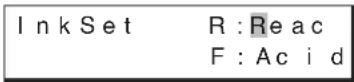

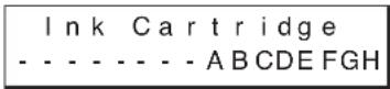
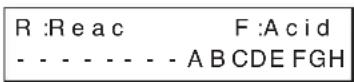

15. Press the [ENTER] key.
Filling of ink is started automatically.
When filling of ink is completed, the display shown on the right is indicated.
16. Press the [END] key twice.
The menu returns to the LOCAL mode.
![Mimaki Tx2-1600 - Press the [END] key twice. - 1](/content/2026/05/919850/images/5909afd7ab435b72d4dccfd5727dfcb3008a01488dba1aff4c387496f640cf3d.jpg)
![Mimaki Tx2-1600 - Press the [END] key twice. - 2](/content/2026/05/919850/images/46a8264bf9a1f0f53c2dafb790f304430f7a17ad1adc305c95e4e735dc85c024.jpg)
![Mimaki Tx2-1600 - Press the [END] key twice. - 3](/content/2026/05/919850/images/c79a149c2a3ed19bba86315320f1d405a47ff1f885abc1c241860a143dd9acb3.jpg)
![Mimaki Tx2-1600 - Press the [END] key twice. - 4](/content/2026/05/919850/images/59cfab99df1da4f8d63e7c89353a7a5f430e3b084eab8be20bc003bb0d8359c4.jpg)
Selecting ink head [USE HEAD]
If nozzle trouble is not recovered, you can change the ink head together with the whole ink station to continue printing.
ALL : Uses both the Front and Rear rows.
REAR : Uses only the Rear row.
FRONT : Uses only the Front row.
![Mimaki Tx2-1600 - Selecting ink head [USE HEAD] - 1](/content/2026/05/919850/images/48e6122ac6eb3fa61a9f3d33fcffdf7aaee887579424bd4aa7bfaa6c6aa5bf16.jpg)
- If different ink types are set in the two ink stations, [USE HEAD] is not displayed and you cannot make setting.
STEPS:
- Select [USE HEAD] from [MAINTENANCE].
(See page 4.3)
MAINTENANCE
USE HEAD <
e n t >
- Press the [ENTER] key.
ENTER
USE HEAD
HEAD LINE : ALL
- Press the JOG keys [▲] and [▼] to select the ink head used.

USE HEAD
HEAD LINE : REAR
[ALL], [REAR], [FRONT]
ENTER
MAINTENANCE
USE HEAD <
e h t >
-
Press the [ENTER] key.
-
Press the [END] key twice.
The menu returns to the LOCAL mode.
END
<
width:1272m m
Check the stretch and shrink of fabric after the printing [STRETCH CHK]
Check whether the cloth is stretching or shrinking after the printing.
The check pattern will be printed at resolution 360 dpi.
Stretch check method
The printing goes as the following order;
cruciform --> fill pattern --> square mark
The stretch condition of the cloth can be verified by the gap between the cruciform and the square mark.
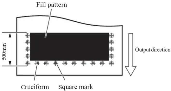
When the cloth is stretched
The square mark will approach the fill pattern.

natural_image
Pure diagram of a rectangular block with internal wavy lines and control square markers (no text or symbols)When the cloth is shrunk
The square mark will move to the outside.

natural_image
Abstract black rectangle with white wavy line and two square cutouts on the left (no text or symbols)STEPS:
-
Select [STRECTH CHK] from [MAINTENANCE]. (See page 4.3)
-
Press the [ENTER] key.
-
Press the JOG keys [ ▲] and [▼ to select the density. [50%], [100%], [200%], [300%]

- 200 % of density is recommended for checking the stretch and shrink on printing at resolution 720 dpi.
-
Press the [ENTER] key.
-
Press the JOG keys [▲] and [▼to select the pass. [4], [8]
-
Press the [ENTER] key.
-
Press the JOG keys [ ▲] and [▼ to select the color. [1A], [2B], [3C], [4D], [5E], [6F], [7G], [8H]
-
Press the [ENTER] key. Start printing the check pattern.
Screen will return to the color selection screen at the end of printing.
- Press the [END] key four times. The menu returns to the LOCAL mode.
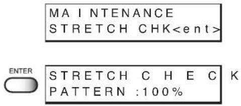
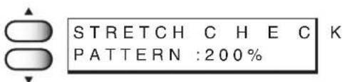





Displaying the printer information [INFORMATION]
Displays the firmware version of this printer.
If trouble occurs, please inform the dealer or MIMAKI sales office of the contents of the trouble as well as this information.
STEPS:
- Select the [INFORMATION] from the [MAINTENANCE].
(See page 4.3)
-
Press the [ENTER] key.
-
Press the [ENTER] key again.
The firmware version is displayed.
- Press the [END] key.
The menu returns to the [Version].
-
Press the JOG keys [ ] and [ ] to select the [Serial No.].
-
Press the [ENTER] key.
-
Press the [END] key four times.
The menu returns to the LOCAL mode.






Chapter 5
When abnormal conditions are encountered
Chapter 5 describes corrective measures to be taken in the case where an abnormal phenomenon arises on the printer and where an error message is given on the display.
Table of contents
Before taking a phenomenon as a sign of failure 5.2
If image quality declines 5.4
Troubles for which error message are given on the LCD 5.5
Before taking a phenomenon as a sign of failure
Corrective measures against troubles in the case where no error message is given on the LCD are described in this section. Be sure to take the following measures before taking the trouble as a sign of failure. If the measures fail restore the printer to the normal state, contact your local MIMAKI distributor or MIMAKI office to call for service.
The printer cannot be energized
More often than not, this is due to improper connection of the power cable. Check that the power cable has been properly connected to the power outlet and the computer.

flowchart
graph LR
    A["Has the power cable been connected to the printer and the receptacle?"] -->|No| B["Securely connect the power cable to them. See page 1.26."]
The printer cannot perform printing
This occurs when the data is not being transmitted to the printer properly. It can also occur when any of the printer functions fails or the fabric has been set improperly.
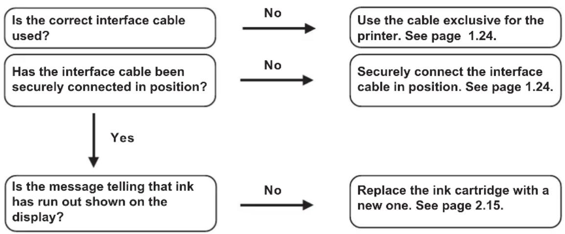
flowchart
graph TD
    A["Is the correct interface cable used?"] -->|No| B["Use the cable exclusive for the printer. See page 1.24."]
    C["Has the interface cable been securely connected in position?"] -->|No| D["Securely connect the interface cable in position. See page 1.24."]
    E["Is the message telling that ink has run out shown on the display?"] -->|Yes| F["Replace the ink cartridge with a new one. See page 2.15."]
    F -->|No| G["End"]
Paper jamming arises/fabric is soiled
A jam of the fabric or a stained fabric is considered to occur when an unsuitable fabric is used or the fabric is set improperly.
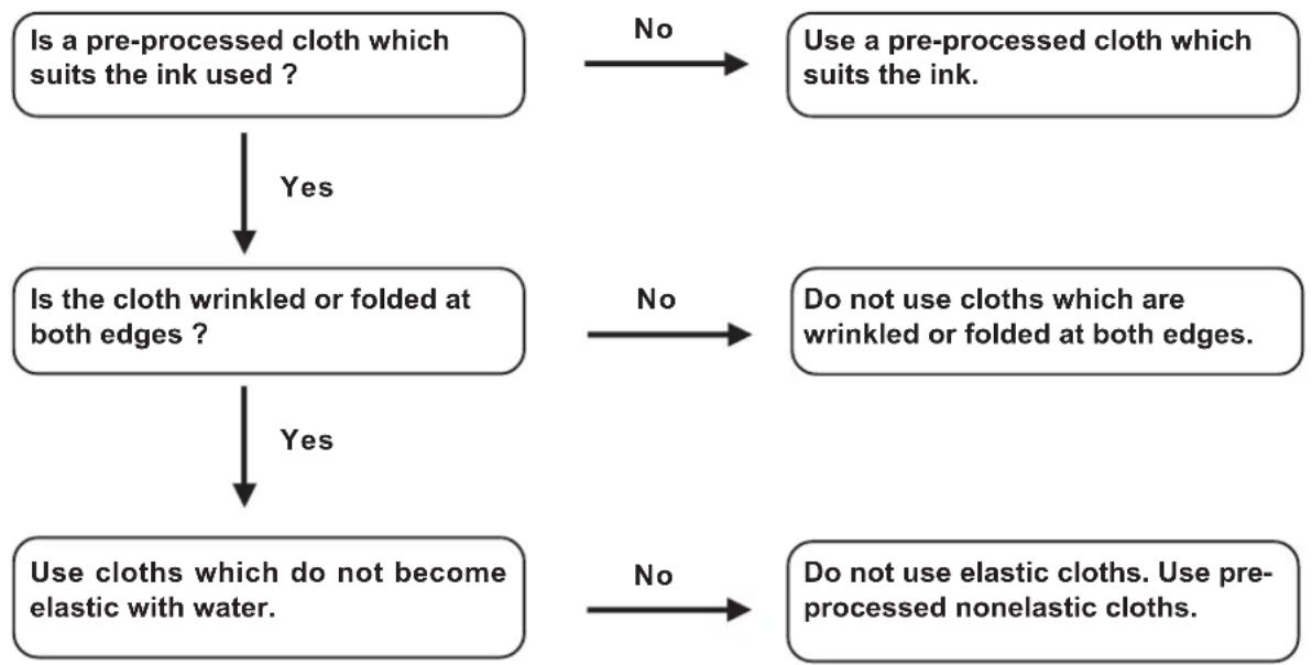
flowchart
graph TD
    A["Is a pre-processed cloth which suits the ink used?"] -->|Yes| B["Is the cloth wrinkled or folded at both edges?"]
    A -->|No| C["Use a pre-processed cloth which suits the ink."]
    B -->|Yes| D["Use cloths which do not become elastic with water."]
    B -->|No| E["Do not use cloths which are wrinkled or folded at both edges."]
    D -->|Yes| F["Do not use elastic cloths. Use pre-processed nonelastic cloths."]
    D -->|No| G["End"]
If image quality declines
Corrective measures against troubles in the case where satisfactory image quality is not provided are described in this station.
Take measures in accordance with actual state of the picture.
If the measures fail restore the printer to the normal state, contact your local MIMAKI distributor or MIMAKI office call for service.
White lines/thin spots are obvious (In the direction of travel of the head)
Corrective measure : Execute the head cleaning. See page 2.12.
Corrective measure : Clean the interior of the station. See page 4.8.
Corrective measure : Execute the MEDIA COMP. See page 3.7.
Displacement is observed between outward and inward printing
Corrective measure : Adjust "Y (outward and inward)" in [PRINTadjust] function. See page 4.6.
The respective color ink injected by the respective color heads do not properly overlap
Corrective measure : Execute the [PRINTadjust] function. See page 4.6.
Troubles for which error message are given on the LCD
If something is wrong with the printer, the buzzer sounds and a corresponding error message is given on the LCD.
Take an appropriate corrective measure in accordance with the message.
Warning message
| Warning message Cause | Corrective measure | |
| Ink Cartridge12 34 5678 ABCDEFG | Ink cartridge is not loaded on the ink station. | Attach the ink cartridge(s) corresponding with the number(s) shown on the display. |
| Ink End12 34 5678 ABCDEFG | The ink cartridge has run out of hink. | |
| Ink Near End12 34 5678 ABCDEFG | The amount of ink remaining in the ink cartridge is insufficient. | |
| Ink Low12 34 5678 ABCDEFG | The amount of ink remaining in the ink cartridge is insufficient to perform ink fill up. | Install the ink cartridge remaining amount is sufficient for ink fill up. |
| WiperReplace Wiper | Time to replace the wiper in the capping station with a new one has come. | Printing can be continued in file-by-file basis by pressing the [RE-MOTE] key. However, it is recommended to replace the wiper as soon as possible. (page 4.11) |
| INK COLOR12345678 ABCDEFGH | The color of the ink cartridge loaded is different from that of the one loaded previously. | Check the color of the ink cartridge with the number displayed. |
| INK KIND12345678 ABCDEFGH | The type of the ink cartridge loaded is different from that of the one loaded previously. | Check the type of the ink cartridge loaded. |
| INK LIMIT12345678 ABCDEFGH | The ink cartridge is expired or almost runs out. | Printing can be continued in file-by-file basis by pushing the [REMOTE] key. However, it is recommended to replace the ink cartridge of which number is shown on the LCD with a new one. |
| INK IC ERROR12345678 ABCDEFGH | The IC chip of the ink cartridge could not be read normally. | Insert an ink cartridge with the displayed number again. If the same error message appears again on the LCD, contact your local distributor to call for service. |
| INK COUNT12345678 ABCDEFGH | The remaining amount of the ink IC is not displayed normally. | |
| Warning message Cause Corrective measure | ||
| The set ink cartridge is not a genuine product. | The message remains displayed until you push the [REMOTE] key. Use a genuine ink cartridge. | |
| Wiper Clean Wiper Shaf | Cleaning period of the ink on the wiper shaft of the capping station. | Perform the carriage-out function of the station maintenance (pages 4.8) to clean the wiper shaft of the capping station. |
| Head Head ID UnRegist. | Head ID has not been registered. | Turn off the power to the printer and turn it on after a while. If the same error message appears again on the LCD, contact your local distributor to call for service. |
| REPLACE BATTERY | Time to replace the battery | Contact your local distributor to call for service. |
| Medi a No Med i a | Clamp lever set down without media.For roll, it means the media is over. | Set upward the clamp lever.Load the new media. |
| Close The Cover | The front cover or the maintenance cover is opened. | Close the front cover or the maintenance cover. |
| Below Oper able Temperature | Temperature is below operable condition. | Adjust environmental temperature. |
| Clamp Lever Lower The Lever | The clamp lever is at high position. Printing and JOG operation cannot be executed. | Lower the clamp lever. |
| <<LOCAL >> CENTERING LIMIT | The movement of the centering device reaches the limit. | Raise the clamp lever and then move the centering device using the centering switch. To forcibly move it, press the [REMOTE] key. |
| <<LOCAL >> TAKE-UP ERROR | The cloth is not took up normally. | Check the condition of the take-up device. |
Error messages
Error messages indicates error numbers.
If any error message is given on the LCD, turn off the power to the printer and turn it on after a while.
If the same error message appears again on the LCD, contact your local MIMAKI distributor or MIMAKI office to call for service.
| Error message Cause | Corrective measure | |
| ERROR 0 1MA I N ROM | Control ROM is defective. | Turn off the power to the printer an turn it on after a while. If the same error message appears again on the LCD, contact your local distributor to call for service. |
| ERROR 0 2MA I N RAM | Control RAM is defective. | |
| ERROR 0 3POWER + 35 V | Power voltage becomes abnormal. | |
| ERROR 0 4F - ROM | Control ROM is defective. | |
| ERROR 0 7TEMP (0000) | Abnormal temperature is detected. | |
| ERROR 0 8LINEAR ENCODER | Trouble with detection of linear encoder. | |
| ERROR 0 9FPGA | Control circuit board is defective.(FPGA Error) | |
| ERROR 0 9FDC | Control circuit board is defective.(HDC Error) | |
| ERROR 1 0COMMAND | The printer has received data other than command data. | Securely connect the interface cable in position. |
| ERROR 1 1PARAMETER | A parameter outside the range of acceptable numeric values is received. | Check the output setting of the host computer. |
| ERROR 1 2MA INTE COMMAND | Maintenance command is abnormal. | Turn off the power to the printer and turn it on after a while. If the same error message appears again on the LCD, contact your local distributor to call for service. |
| ERROR 1 3RIP LINK | Irregular in receiving data. | |
| ERROR 1 4COLOR COMMAND | Color command is abnormal. | |
| ERROR 2 0I/F BOARD | An error occurs in communication between I/F board and main board. | Turn off the power to the printer and turn it on after a while. If the same error message appears again on the LCD, contact your local distributor to call for service. |
| ERROR 2 1I/F NONE | I/F board has not been installed. | Install the I/F board. |
| ERROR 2 3HOST I / F | HOST I/F Timeout error has arisen during communication between the host computer and interface board. | Check to be sure that the cable is securely connected to the host computer and interface board. Also, check to ascertain that no error has arisen on the host computer side. |
| ERROR 2 4I/F INITIAL | Initial operation failure of the I/F board and control board. | Turn off the power to the printer and turn it on after a while. If the same error message appears again on the LCD, contact your local distributor to call for service. |
| ERROR 3 0OPERATION | Improper operation has been conducted on the operation panel. | Perform a proper operation. |
| ERROR 3 4DATA REMAIN | Settings for functions have been tried to be changed though there remains received data that has not yet been printed. | Print all pieces of received data or execute the data clear function. Then, change the settings. |
| ERROR 4 0MOTOR X | The Xmotor has been overload. | Turn off the power to the printer and turn it on after a while. If the same error message appears again on the LCD, contact your local distributor to call for service. |
| ERROR 4 1MOTOR Y | The Ymotor has been overload. | |
| ERROR 4 2X OVER CURRENT | Overcurrent error on the Xmotor has been detected. | |
| ERROR 4 3Y OVER CURRENT | Overcurrent error on the Ymotor has been detected. | |
| ERROR 4 5CAPPING | Incorrect height of the capping station has been detected. | |
| ERROR 4 6WIPING | The wiping device is defective. | |
| ERROR 50MEDIASENSE | The printer has failed to detect the fabric. | Both edges of the set cloth are not positioned properly.If an error is displayed after setting it properly, contact your dealer or MIMAKI sales office. |
| ERROR 51YORIGIN | The printer has failed to detect the origin. | Turn off the power to the printer and turn it on after a while. If the same error message appears again on the LCD, contact your local distributor to call for service.Check the connection. |
| ERROR 60TAKE - UP UNIT | The take-up unit error has been occurred because of sensor error. | Turn off the power to the printer and check the connection of the cable of the take-up unit. When the same error message appears again on the LCD even if the cable is connected properly, contact your local distributor to call for service. |
| ERROR 62CENTERING UNIT n | The centering unit error has been occurred. The centering unit has not been connected properly.01: Sensor NONE02: Unit NONE | Turn off the power to the printer and check the connection of the cable of the centering unit. When the same error message appears again on the LCD even if the cable is connected properly, contact your local distributor to call for service. |
Appendix
This appendix describes the specifications and components the printer, function menu structure.
Table of contents
Basic specifications ...... A.2
Ink Specification....A.3
Optional extras....A.4
Function flow chart.... A.5
| Item Tx2-1600 | ||
| Printing head | Method Piezo-electric drop on demand | |
| Specification Eight | ht-heads (4 x 2 lines, Stagger arrangement) | |
| Nozzle Multi ink set printing: 360 nozzles for each color | ||
| Printing speed High | high speed printing: 720 nozzles for each color | |
| Resolution 360 , 540, 720 dpi | ||
| Drawing mode | Multi ink setting 360 x 360 dpi : 2 / 4 / 8 passes, Unidirection / bidirection | |
| High speed setting | 360 x 360 dpi : 1 / 2 / 4 passes, Unidirection / bidirection | |
| Ink type | Acid dye ink | Color (Black, Cyan, Magenta, Yellow, Light Cyan, Light Magenta, Gray, Blue, Red) |
| Disperse dye ink | Color (Black, Cyan, Magenta, Yellow, Light Cyan, Light Magenta, Gray, Blue, Light Blue) | |
| Reactive dye ink | Color (Black, Cyan, Magenta, Yellow, Light Cyan, Light Magenta, Gray, Blue, Orange, Red, Golden Yellow) | |
| Ink set 2 way setting 1 cartridge per 1 color | ||
| Delivery system of ink Tube supplying from the ink cartridge. | ||
| Capacity of ink cartridge | 220 cc ± 10 cc per cartridge (x1 for2 way or x2 for1way)About 200cc can be used for each cartridge. | |
| Fabric type The following cloths are excluded.Cloths which become elastic with waterCloths with high elasticityCurled or folded cloths | ||
| Max. Printing width 1620 mm | ||
| Fabric size(Roll fabric)* | Thickness | 7.0 mm or less |
| Outside diameter | 180 or less | |
| Roll weight | 15 kg or less | |
| Roll inside diameter | 1.5 to 3 inch | |
| Printing surface | Printing can be made on either side. | |
| Roll end treatment | Light-adhesive tape is used to allow the paper to be removed from the core with ease. | |
| Margin(Roll fabric) | Left end | 10 mm ± 0.5 mm |
| Right end | 10 mm ± 0.5 mm | |
| Distance accuracy | Absolute accuracy | Whichever the larger one of ± 0.5 mm or ±0.3 % of the designated |
| Reoroducibility | Whichever the larger one of ± 0.5 mm or ±0.3% of the designated | |
| Perpendecularity | ± 0.5 mm / 1000 mm | |
| Item | Tx2-1600 | |
| Fabric skew 5 mm or less / 10 m | (In case the fabric is aligned.) | |
| Head height adjustment 1.2 mm to 10 mm variable from the platen surface | ||
| Cutting of fabric Cutter function not provided. | ||
| Waste ink tank Waste ink hose is packaged standard (Waste ink tank not provided) | ||
| Interface IEEE1394, IEEE1284 | ||
| Command MRL-1E (ESC/PV.1 base) Mimaki original command | ||
| Noise during standby Less than 56 dB (FAST-A, back and forth and around.) | ||
| Noise during continuous printing Less than 66 dB | ||
| Noise during discontinuous printing Less than 70 dB | ||
| Power AC 100 - 240 V ±10% (Auto voltage) | ||
| Power consumption 500 W or less | ||
| Recommended Environment | Temperature 15 - 30 °C | |
| Humidity 35 - 65 % Rh (No condensation) | ||
| Accuracy-guaranteed temperature | 18 - 25 °C | |
| Temperature change | ± 10 °C / h or less | |
| Dust Equivalent to normal office level | ||
| Weight 210 kg | ||
| Outside Width dimensions | 2750 mm | |
| Depth | 780 mm | |
| Height | 1350 mm | |
Ink Specification
| Item | Specifications |
| Form | Ink cartridge exclusive to the device |
| Acid dye ink | Ink cartridge (SPC-0355 Series) |
| Disperse dye ink | Ink cartridge (SPC-0356 Series) |
| Reactive dye ink | Ink cartridge (SPC-0357 Series) |
| Contents of ink cartridge | 220 cc per cartridge |
| Shelf life | Two years from the data of manufacture (at room temperature) Described on the cartridge. |
| Within six months after opening the package Within the expiration period described on the cartridge. | |
| Storage temperature During storage: | -30 to 40 °C(Storage at temperature of 40°C is permitted within a month.) |
| Storage temperature During transportation: | -30 to 60 °C(Storage at temperature of 60°C is only permitted within 120 hours, and at temperature of 40°C is permitted within a month.) |
Optional extras
| Item Item no. | Qty. Remarks | ||
| Ink cartridge See the list above. | |||
| Bemcot BEMCOT M-3 100 pcs. | |||
| Swab Swab 6 wooden shaft S 10 pcs. | |||
| Wiper SPA-0105 4 pcs. | |||
| Washing liquid bottle kit PC-0137 1 set For routine maintenance. | |||
| Washing liquid cartridgePC-0422 | 220 cc Cartridge | ||
| RIP software | A101644 1 set RasterLink Pro | ||
| Computer installed RIP | A101645 1 set Computer installed | RasterLink Pro | |
Function flow chart
Setting fabric;

flowchart
graph TD
    A["MEDIA SET ROLLS > LEAF"] --> B["Centering .OFF TAKE-UP DEV. :OFF"]
    B --> C["DETECTING MEDIA PLEASE WAIT"]
    C --> D["« MEDIA » X:**** Y:****"]
    D --> E["<<LOCAL>> width:1820mm"]
    F["Media SELECT CAPACITY = 110 m"] --> G["DETECTING MEDIA PLEASE WAIT"]
    G --> H["« MEDIA » X:**** Y:****"]
    H --> I["<<LOCAL>> width:1820mm"]
    J["Roll"] --> K["Set media length (3 to 650 m)"]
Origin setting;

TEST key; TEST

DATA CLEAR key;

CLEANING key:

Guidance;

flowchart
graph LR
    A["<<LOCAL>> X=xxxx Y=xxxx"] --> B["Ink Level 3231780745990253"]
    C["<REMOTE> X=xxxx Y=xxxx"] --> B
    B --> D["Media Wt. =xxxmm\nRamina =xxxmm"]
    D --> E["InxSet R. Acid F. Disp"]
    E --> F["Head Height +mm"]
    F --> G["Ver1.00 MRL-1E"]
    G --> H["SETUP <TYPE1> Display [V"] Key]
    H --> I["Error Info Display [V"] Key]
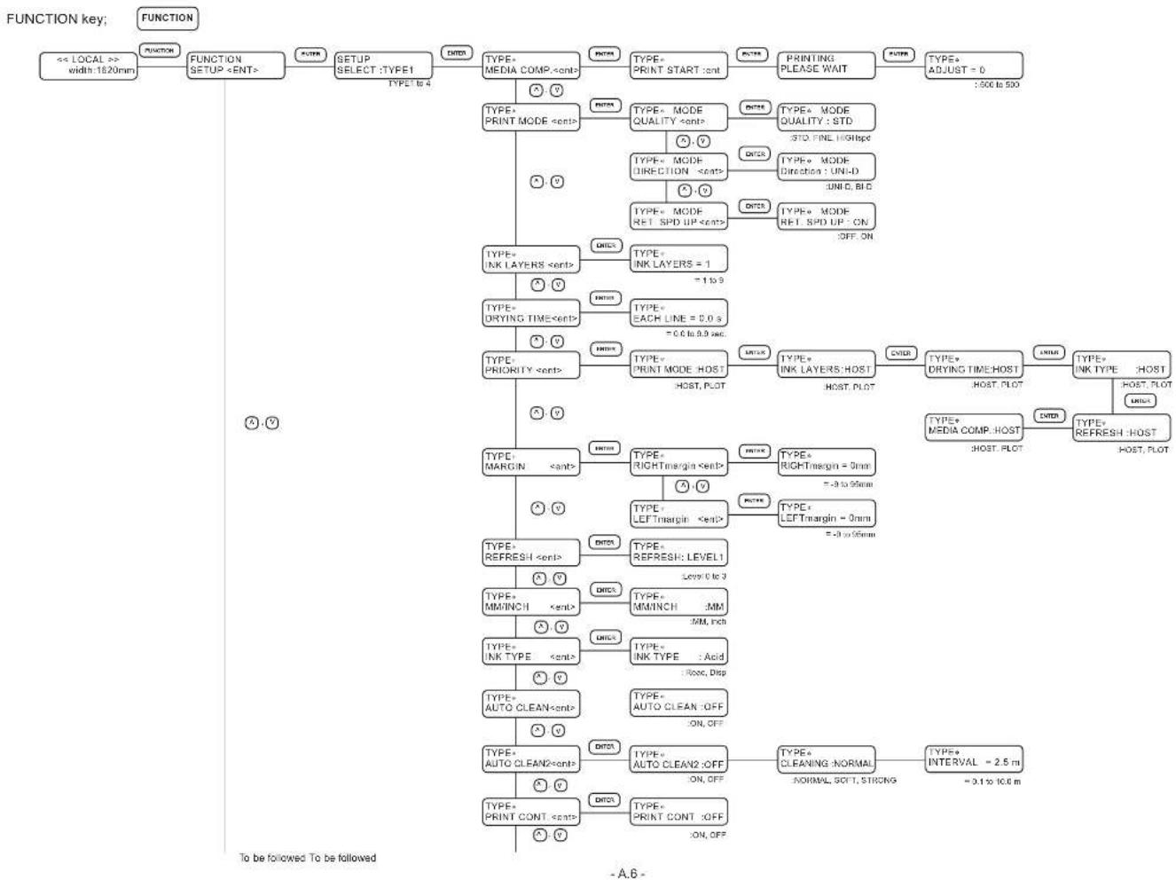
flowchart
graph TD
    A["<< LOCAL >> width:1620mm"] --> B["FUNCTION SETUP <ENT>"]
    B --> C["PUTER"]
    C --> D["SETUP SELECT:TYPE1"]
    D --> E["TYPE-MEDIA_COMP <cont>"]
    E --> F["TYPE-PRINT START:cont"]
    F --> G["TYPE-PRINTING PLEASE WAIT"]
    G --> H["TYPE+ADJUST = 0 :500 to 500"]
    B --> I["TYPE-PRINT MODE <cont>"]
    I --> J["TYPE-MODE QUALITY <cont>"]
    J --> K["TYPE+MODE QUALITY: STD :STD, FINE, HIGHpe"]
    I --> L["TYPE-DRYING TIME <cont>"]
    L --> M["TYPE-EACH LINE = 0.0 s = 0.0 to 9.9 sec"]
    M --> N["TYPE-PRIORITY <cont>"]
    N --> O["TYPE-PRINT MODE:HOST :HOST, PLOT"]
    O --> P["TYPE+INK LAYERS:HOST :HOST, PLOT"]
    O --> Q["TYPE+DRYING TIME:HOST :HOST, PLOT"]
    O --> R["TYPE+INK TYPE:HOST :HOST, PLOT"]
    O --> S["TYPE+MEDIA_COMP:HOST :HOST, PLOT"]
    S --> T["TYPE+REFRESH:HOST :HOST, PLOT"]
    S --> U["TYPE+REFRESH:LEVEL1 :Low 0 to 3"]
    U --> V["TYPE-MMINCH :MM /MM, Pitch"]
    V --> W["TYPE+INK TYPE :Acid :Roo, Disp"]
    W --> X["TYPE-AUTO CLEAN :OFF :ON, Off"]
    X --> Y["TYPE-AUTO CLEAN2 :cont>"]
    Y --> Z["TYPE-AUTO CLEAN2 :OFF :ON, Off"]
    Z --> AA["TYPE-CLEANING:NORMAL :NORMAL, SOFT, STRONG = 3.1 to 10.0 m"]
    Z --> AB["TYPE+INTERVAL = 2.5 m :OFF"]
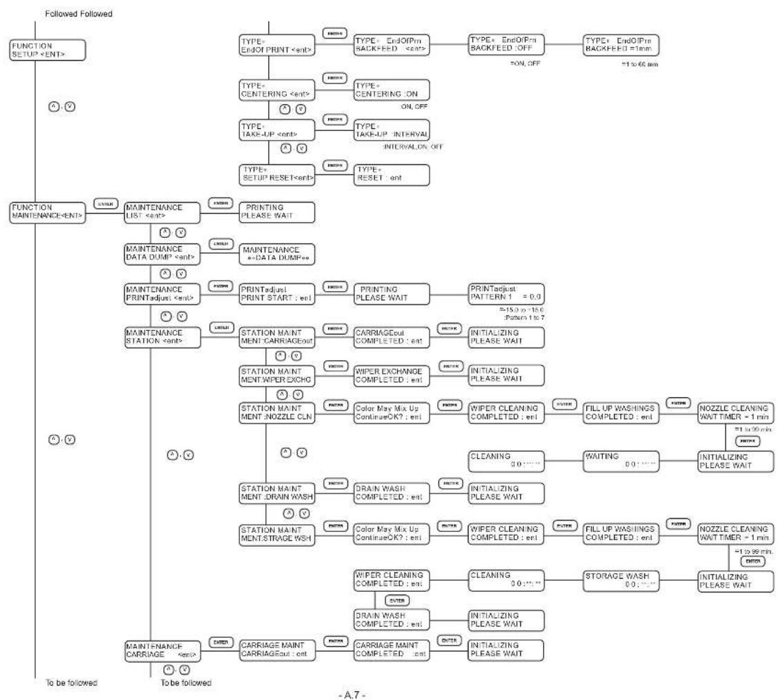
flowchart
graph TD
    A["FUNCTION SETUP <ENT>"] --> B["TYPE+ EndOf PRINT <ent>"]
    B --> C["TYPE+ Centering <ent>"]
    C --> D["TYPE+ TAKE-UP <ent>"]
    D --> E["TYPE+ SETUP RESET <ent>"]
    E --> F["TYPE+ RESET :ent"]
    F --> G["PRINTING PLEASE WAIT"]
    G --> H["MAINTENANCE DATA DUMP <ent>"]
    H --> I["MAINTENANCE PRINTadjust <ent>"]
    I --> J["MAINTENANCE STATION <ent>"]
    J --> K["STATION MAINT MENT:CARRIAGEout"]
    K --> L["STATION MAINT MENT:WIPER EXCHG"]
    L --> M["STATION MAINT MENT:NOZZLE CLN"]
    M --> N["STATION MAINT MENT:DRAIN WASH"]
    N --> O["STATION MAINT MENT:STRAGE WSH"]
    O --> P["CAIRAGE MAINT CARRIAGEout :ent"]
    P --> Q["PRINTING PLEASE WAIT"]
    Q --> R["PRINTAdjust PRINT START :ent"]
    R --> S["STATION MAINT MENT:CARRIAGEout"]
    S --> T["WIPER EXCHANGE COMPLETED :ent"]
    T --> U["Color May Mix Up ContinueOK? :ent"]
    U --> V["RAIN WASH COMPLETED :ent"]
    V --> W["COLOR May Mix Up ContinueOK? :ent"]
    W --> X["WIPER CLEANING COMPLETED :ent"]
    X --> Y["WIPER CLEANING COMPLETED :ent"]
    Y --> Z["CRAIRAGE MAINT COMPLETED :ent"]
    Z --> AA["CRAIRAGE MAINT COMPLETED :ent"]
    AA --> AB["CRAIRAGE MAINT COMPLETED :ent"]
    AB --> AC["CRAIRAGE MAINT COMPLETED :ent"]
    AC --> AD["CRAIRAGE MAINT COMPLETED :ent"]
    AD --> AE["CRAIRAGE MAINT COMPLETED :ent"]
    AE --> AF["CRAIRAGE MAINT COMPLETED :ent"]
    AF --> AG["CRAIRAGE MAINT COMPLETED :ent"]
    AG --> AH["CRAIRAGE MAINT COMPLETED :ent"]
    AH --> AI["CRAIRAGE MAINT COMPLETED :ent"]
    AI --> AJ["CRAIRAGE MAINT COMPLETED :ent"]
    AJ --> AK["CRAIRAGE MAINT COMPLETED :ent"]
    AK --> AL["CRAIRAGE MAINT COMPLETED :ent"]
    AL --> AM["CRAIRAGE MAINT COMPLETED :ent"]
    AM --> AN["CRAIRAGE MAINT COMPLETED :ent"]
    AN --> AO["CRAIRAGE MAINT COMPLETED :ent"]
    AO --> AP["CRAIRAGE MAINT COMPLETED :ent"]
    AP --> AQ["CRAIRAGE MAINT COMPLETED :ent"]
    AQ --> AR["CRAIRAGE MAINT COMPLETED :ent"]
    AR --> AS["CRAIRAGE MAINT COMPLETED :ent"]
    AS --> AT["CRAIRAGE MAINT COMPLETED :ent"]
    AT --> AU["CRAIRAGE MAINT COMPLETED :ent"]
    AU --> AV["CRAIRAGE MAINT COMPLETED :ent"]
    AV --> AW["CRAIRAGE MAINT COMPLETED :ent"]
    AW --> AX["CRAIRAGE MAINT COMPLETED :ent"]
    AX --> AY["CRAIRAGE MAINT COMPLETED :ent"]
    AY --> AZ["CRAIRAGE MAINT COMPLETED :ent"]
    AZ --> BA["CRAIRAGE MAINT COMPLETED :ent"]
    BA --> BB["CRAIRAGE MAINT COMPLETED :ent"]
    BB --> BC["CRAIRAGE MAINT COMPLETED :ent"]
    BC --> BD["CRAIRAGE MAINT COMPLETED :ent"]
    BD --> BE["CRAIRAGE MAINT COMPLETED :ent"]
    BE --> BF["CRAIRAGE MAINT COMPLETED :ent"]
    BF --> BG["CRAIRAGE MAINT COMPLETED :ent"]
    BG --> BH["CRAIRAGE MAINT COMPLETED :ent"]
    BH --> BI["CRAIRAGE MAINT COMPLETED :ent"]
    BI --> BJ["CRAIRAGE MAINT COMPLETED :ent"]
    BJ --> BK["CRAIRAGE MAINT COMPLETED :ent"]
    BK --> BL["CRAIRAGE MAINT COMPLETED :ent"]
    BL --> BM["CRAIRAGE MAINT COMPLETED :ent"]
    BM --> BN["CRAIRAGE MAINT COMPLETED :ent"]
    BN --> BO["CRAIRAGE MAINT COMPLETED :ent"]
    BO --> BP["CRAIRAGE MAINT COMPLETED :ent"]
    BP --> BQ["CRAIRAGE MAINT COMPLETED :ent"]
    BQ --> BR["CRAIRAGE MAINT COMPLETED :ent"]
    BR --> BS["CRAIRAGE MAINT COMPLETED :ent"]
    BS --> BT["CRAIRAGE MAINT COMPLETED :ent"]
    BT --> BU["CRAIRAGE MAINT COMPLETED :ent"]
    BU --> BV["CRAIRAGE MAINT COMPLETED :ent"]
    BV --> BW["CRAIRAGE MAINT COMPLETED :ent"]
    BW --> BX["CRAIRAGE MAINT COMPLETED :ent"]
    BX --> BYC["CRAIRAGE MAINT COMPLETED :ent"]
    BYC --> BZ["CRAIRAGE MAINT COMPLETED :ent"]
    BZ --> CA["CRAIRAGE MAINT COMPLETED :ent"]
    CA --> CB["CRAIRAGE MAINT COMPLETED :ent"]
    CB --> CC["CRAIRAGE MAINT COMPLETED :ent"]
    CC --> CD["CRAIRAGE MAINT COMPLETED :ent"]
    CD --> CE["CRAIRAGE MAINT COMPLETED :ent"]
    CE --> CF["CRAIRAGE MAINT COMPLETED :ent"]
    CF --> CG["CRAIRAGE MAINT COMPLETED :ent"]
    AG --> CH["TO BE FOLLOWED"]
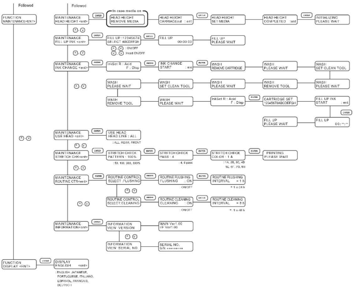
flowchart
graph TD
    A["FUNCTION MAINTENANCE<ENT>"] --> B["MAINTENANCE HEAD HEIGHT <ent>"]
    B --> C{In case media on HEAD HEIGHT REMOVE MEDIA}
    C -->|YES| D["HEAD HEIGHT CARRIAGEOUT : ent"]
    C -->|NOXX| E["HEAD HEIGHT SET MEDIA"]
    E --> F["HEAD HEIGHT COMPLETED : ent"]
    F --> G["LIVIAT"]
    G --> H["INITIALIZING PLEASE WAIT"]

    A --> I["MAINTENANCE FILL UP INK <ent>"]
    I --> J{FILL UP :12345678 SELECT ABCDEFGH}
    J -->|YES| K["FILL UP 00:00:00"]
    J -->|NOXX| L["FILL UP PLEASE WAIT"]
    L --> M{O : ON/OFF O : Head ON/OFF}

    A --> N["MAINTENANCE INK CHANGE <ent>"]
    N --> O{INKSet R : Acid F : Disp}
    O -->|YES| P["INK CHANGE START : ent"]
    O -->|NOXX| Q["WASH REMOVE CARTRIDGE"]
    Q --> R["WASH PLEASE WAIT"]
    R --> S["WASH SET CLEAN TOOL"]
    S --> T["WASH PLEASE WAIT"]
    T --> U["WASH REMOVE TOOL"]
    U --> V["WASH PLEASE WAIT"]

    A --> W["MAINTENANCE USE HEAD <ent>"]
    W --> X{USE HEAD HEAD LINE : ALL : ALL REAR FRONT}
    X -->|YES| Y["MAINTENANCE STRETCH CHK<ent>"]
    Y --> Z{STRETCH CHECK PATTERN : 100% : 50, 100, 200, 300%}
    Z -->|YES| AA["STRETCH CHECK PASS : 4 : 4, 8 pass"]
    Z -->|NOXX| AB["STRETCH CHECK COLOR : 1 A : 1A, 2B, 3C, 4D SE, 6F, 7G, 8H"]
    AA --> AC["PRINTING PLEASE WAIT"]

    A --> AD["MAINTENANCE ROUTINE CTR<ent>"]
    AD --> AE{ROUTINE CONTROL SELECT :FLUSHING}
    AE -->|YES| AF["ROUTINE FLUSHING FLUSHING : ON : ON/OFF"]
    AE -->|NOXX| AG["ROUTINE FLUSHING INTERVAL = 1 h = 1 to 24 h"]

    A --> AH["MAINTENANCE INFORMATION<ent>"]
    AH --> AI{INFORMATION VIEW VERSION}
    AI -->|YES| AJ["INFORMATION VIEW SERIAL NO"]
    AI -->|NOXX| AK["INFORMATION VIEW SERIAL NO"]
    AI -->|SERIAL NO. SIN reference]

    A --> AL["FUNCTION DISPLAY <=NT>"]
    AL --> AM{DISPLAY ENGLISH <ent>}
    AM -->|YES| AN["ENGLISH, JAPANESE, PORTUGUESE, ITALIANO, ESPAVOL, FRANCAS, DEUTSCH"]
D201546-1.00-31052006
Mimaki
Printed in Japan
D201546
© MIMAKI ENGINEERING CO., LTD. 2006
- The kinds of manuals and how to use them
- Operation Manual (this document)
- Foreword
- DISCLAIMER OF WARRANTY
- On this Operation Manual
- FCC Statement (USA)
- Interference to televisions and radios
- TABLE OF CONTENTS
- Foreword ...... i
- Features......viii
- How to read this Operation Manual .... x
- For safe operation....xiv
- Chapter 1 Setup
- Installation of the printer 1.2
- Checking the accessories 1.4
- Unpacking and Assembling.... 1.6
- Configuration and Fction 1.13
- Names and function of the parts under the front cover 1.15
- Chapter 2 How to use the basic functions
- Chapter 3 How to use the application functions
- Chapter 4 Maintenance functions
- Chapter 5 When abnormal conditions are encountered
- Appendix
- Features
- Setting for 2-way multi printing
- types of textile printing ink can be used
- Applicability of fabrics up to 7mm in thickness
- Applicable to wide fabrics
- Indication of the amount of remaining ink
- Easy-to-see display
- Display of information for confirmation
- High-speed interface
- Fabric retainer
- Ditch for penetrated ink
- Slip sheet can be used
- Function of feed-correction
- Centering (anti-meandering) mechanism
- Display on the LCD and indication of the keys
- Display on the LCD
- Operation keys
- Safety symbols used in this Manual
- Safety signal words
- Structure of this Manual
- For safe operation
- Warnings in use
- WARNING
- Precautions in use
- CAUTION
- Position of the warning label
- Installation of the printer
- Where to install the printer
- Precautions in installation
- Checking the accessories
- NOTE!
- Unpacking and Assembling
- Assembling the stand and the device
- STEP
- Remove the four bolts that fixes the packed pedestals and packed pads.
- Take the main unit together with the packed pedestals out of the package and place them on the floor.
- Take the stands out of the package.
- Attach the take-up device stand stay to the leg.
- Lock the stand stoppers.
- Holding both ends of the main unit with four persons.
- Place the main unit on the stands while exercising care not to allow hands to be caught between them.
- Set the take-up device stand stay in position.
- Attaching take-up auxiliary bar
- Attaching loading auxiliary bar
- Attaching centering sensor unit
- Attaching loading unit
- Connecting connectors and cables
- How to remove the stopper
- Putting on the maintenance cover
- Attaching slip sheet bar
- Preparing the waste ink tank
- Configuration and Function
- Front face
- Rear face
- Names and function of the parts under the front cover
- Carriage
- Capping station
- The pinch roller and feed roller
- The media sensor
- Head hight adjustment rod and adjustment screw
- Fabic retainer
- Ditch for penetrated ink and platen boards
- About other setup
- Attaching lapel bar
- STEPS:
- Attaching the platen boards
- Changing gap for fabic retainers
- Installing IEEE1394 output driver
- Connecting the cables
- Connecting the interface cable
- For Windows 2000, XP (IEEE1394)
- Configuration of connector (IEEE1394)
- For other operating system (IEEE1284)
- Configuration of connector (IEEE1284)
- Connecting the power cable
- Switching ON/OFF the power supply
- Turning the power on
- Turning the power off
- Front cover and maintenance cover
- Opening/closing the cover
- When opening the cover during printing
- Ink cartridges
- Types of ink
- Precautions in handling the ink cartridge
- Ink stations
- Relationships between ink station and head row
- Display of ink type
- Setting ink cartridges
- Setting for 1-way high-speed printing
- Fabric for printing
- Types of fabic that can be used
- Precautions in handling the fabric
- Limited media
- Before setting the fabric on the printer
- Adjusting the head height according to the fabic [HEAD HEIGHT]
- Press the [ENTER] key.
- Points in head height adjustment
- Optimum distance
- Distance increased
- Setting the mating sheet
- Adjusting parallelism of loading unit
- Setting The FabricTo The Printer
- Setting a roll fabic
- Center the centering indicator.
- Insert the let-hand roll holder into the core of the roll fabric.
- Loosen the screw of the right-hand roll holder.
- Insert the right-hand roll holder into the core of the roll fabric.
- Viewing from the rear side of the printer, align the left edge of the roll with the scale of the fabric setting position plate.
- Pull out the leading edge of the fabric from the front face of the printer.
- Rewind the roll holder or fabric core several times from the rear face of the printer.
- M ove down the clamp lever on the front face of theprinter.
- Setting the centering sensor position
- Attaching empty fabic core for taking up
- Removing pinch roller and preventing wrinkle of fabic
- Specifying the scope of printing on the fabric used (Effective printing area)
- Origin setting
- Setting of an origin
- Moving the printer
- Chapter 2
- How to use the basic functions
- Operation
- Operation panel
- JOG keys [][N][]
- [TEST] key
- [FUNCTION] key
- [END] key
- [CLEANING] key
- Display
- POWER lamp
- [DATA CLEAR] key
- [REMOTE] key
- [ENTER] key
- Functions of the JOG keys
- MENU mode
- <> mode
- << REMOTE >> mode
- Menu tree
- [Operation key] DISPLAY
- Setting the display language
- Printing an image from source data
- Starting the printer operation
- Turn the power on.
- Set the fabric in position.
- Press the [REMOTE] key.
- The printer receives the data from the computer.
- Start the printing.
- After the printing operation is completed, press the [REMOTE] key to put the mode back into the LOCAL mode.
- Information on printing data
- Key operation on REMOTE mode
- Correcting the media feed rate during printing [Feed Comp.]
- Press the [FUNCTION] key on REMOTE mode.
- Press the [ENTER] key.
- Press the JOG key [] or [] as needed to set the amount of correction.
- Press the [ENTER] key.
- Press the [ENTER] key to return to the REMOTE display.
- Interrupting the printing operation
- Checking nozzle in ink firing condition
- Executing the test draw [TEST DRAW]
- Make sure the mode is LOCAL mode.
- Press the [TEST] key.
- Press the [ENTER] key.
- When test printing is performed during host data printing, press the [REMOTE] key.
- Checking the test patterns
- If there are nozzle clogging in ink firing condition
- Cleaning ink heads
- Routine maintenance
- When the device is left unused for a long period of time
- Notes on cleaning
- Cleaning ink at the bottom of the slider
- Cleaning wiper
- Cleaning the wiper shaft
- Maintenance for frame components
- Cleaning penetrated ink
- To replenish ink, set a new ink cartridge in the ink station
- - When the amount of ink becomes small during printing.
- - When the amount of ink completely runs out during printing.
- Either of the messages shown above is displayed on the LCD during printing.
- Install a new ink cartridge.
- Chapter 3
- How to use the application functions
- Application functions
- Function menu
- [SETUP]/[DISPLAY]
- Before setting printing conditions in the function menu
- Checking the menu mode
- Registering Two or More Printing Conditions at a Time (Selecting a Type)
- Changing the type
- Adjusting the lapal bar
- Troubleshooting
- After setting the fabric to be printed
- Correcting error of amount of feed depending on fabric [MEDIA COMP.]
- Select a type.
- Enter a correction value from the output pattern.
- Press the [ENTER] key.
- Press the [END] key twice.
- Setting printing conditions
- Changing printing conditions on the printer side
- Relationship between image quality and printing speed [QUALITY]
- Printing direction [DIRECTION]
- Returning speed up [RET. SPD UP]
- Improving the density of ink color [INK LAYERS]
- Setting the ink drying time [DRYING TIME]
- Deciding the priority of settings by the computer or the plotter [PRIORITY]
- Increasing (decreasing) the right and left margins of the fabric [RIGHTmargin]/[LEFTmargin]
- Setting [RIGHTmargin]
- Setting [LEFTmargin]
- When using the plotter in an extremely dusty or dry place [REFRESH]
- Setting a unit of length displayed on the LCD [MM/INCH]
- Setting the type of ink to be used [INK TYPE]
- Setting up auto-cleaning function [AUTO CLEAN]
- Setting up auto-cleaning function [AUTO CLEAN2]
- Press the [ENTER] key.
- Press the JOG keys [] and [] to select the length to execute the cleaning performance.
- P ress the [END] key twice.
- Back feed Setting for End of printing [EndOf PRINT]
- Continuing printing after [Ink Near End] [PRINT CONT.]
- Preventing the fabric skew [CENTERING]
- Enabling the take-up unit [TAKE-UP]
- Resetting printing conditions by type [SETUP RESET]
- Chapter 4
- Maintenance functions
- Maintenance of the printer
- Function menu [MAINTENANCE]
- Before starting maintenance
- Invoking a maintenance function
- Press the [FUNCTION] key.
- Press the JOG keys [ ▲] and [▼ to select [MAINTENANCE].
- Select the next operation.
- Drawing setup conditions [LIST]
- Explanation of the list
- Select [LIST] from [MAINTENANCE].
- Printing HEX code of printing command [DATA DUMP]
- Select [DATA DUMP] from [MAINTENANCE].
- When printing is completed, press the [REMOTE] key.
- Press the [DATA CLEAR] key.
- Press the [ENTER] key.
- Correcting the dot positions after adjusting the head height [PRINTadjust]
- Select [PRINTadjust] from [MAINTENANCE].
- Press the JOG keys [] and [] to correct the dot position of pattern 1.
- Repeat Steps 4 and 5 to correct the dot positions on Patterns 2 to 7.
- Moving the carriage to clean the station interior [CARRIAGEout]
- If a defective printing is not corrected even after the cleaning function is executed
- Cleaning the ink caps
- Periodical cleaning of the wiper
- Cleaning the wiper
- Notes on handling the wipers
- When the message [Replace Wiper] is displayed [WIPER EXCHG]
- Holding the projections at both ends, insert a new wiper into place.
- Clean the wiper guide shaft using a swab or cloth.
- Close the maintenance cover, then press the [ENTER] key.
- When the message [Clean Wiper Shaft] is displayed
- Cleaning Tools :
- Clean the wiper.
- Ink discharge way cleaning [DRAIN WASH]
- When not in use the machine over the long term [STORAGE WSH]
- Holding the projections at both ends, draw out the wiper.
- Use a swab soaked with the cleaning liquid to clean off ink blots on wiper and bracket.
- Holding the projections at both ends, insert a clean wiper into place.
- F ill the cap with the cleaning liquid using a syringe.
- Move the carriage to the left maintenance station [CARRIAGE]
- Close the left maintenance cover, then press the [ENTER] key.
- Adjusting the head height when the fabric used is changed [HEAD HEIGHT]
- Menu displayed after the ink cartridge is installed [FILL UP INK]
- Select [FILL UP INK] from [MAINTENANCE].
- Press the JOG keys [ ▲] [▼] [ ]▶ to select the head to be filled up.
- Press the [END] key twice.
- When charging ink different from the one in use [INK CHANGE]
- Select [INK CHANGE] from [MAINTENANCE].
- Press the JOG keys [] and [] to set the type of ink to be filled in the R-row ink station.
- Press the JOG key []to move the cursor.
- Press the JOG keys [▲] and [▼] to set the type of ink to be filled in the F-row ink station.
- Press the [ENTER] key.
- Take out the changing ink cartridge from the ink station.
- When the LCD shown on the right appears, install the washing liquid cartridge.
- When the LCD shown on the righti appears, take out the washing liquid cartridge from the ink station.
- R epeat steps 9 and 10.
- Check the type and number of ink set.
- Press the [ENTER] key.
- Insert the ink cartridges to the ink stations.
- Press the [ENTER] key.
- Press the [END] key twice.
- Selecting ink head [USE HEAD]
- Check the stretch and shrink of fabric after the printing [STRETCH CHK]
- Stretch check method
- When the cloth is stretched
- When the cloth is shrunk
- Displaying the printer information [INFORMATION]
- Chapter 5
- When abnormal conditions are encountered
- Before taking a phenomenon as a sign of failure
- The printer cannot be energized
- The printer cannot perform printing
- Paper jamming arises/fabric is soiled
- If image quality declines
- White lines/thin spots are obvious (In the direction of travel of the head)
- Displacement is observed between outward and inward printing
- The respective color ink injected by the respective color heads do not properly overlap
- Troubles for which error message are given on the LCD
- Error messages
- Function flow chart
- Mimaki
Brand : Mimaki
Model : Tx2-1600
Category : Printer