GEMINI HSC - Boiler Elco - Free user manual and instructions
Find the device manual for free GEMINI HSC Elco in PDF.


| Product Type | Gas condensing boiler |
| Brand | Elco |
| Model | GEMINI HSC |
| Dimensions (H x W x D) | Approx. 800 x 450 x 350 mm |
| Weight | Approx. 40 kg |
| Power Supply | 230 V / 50 Hz |
| Gas Type | Natural gas or propane |
| Heat Output | Up to 30 kW |
| Efficiency | Up to 98% (condensing) |
| Main Functions | Central heating and domestic hot water production |
| Control Type | Electronic control with LCD display |
| Flow Temperature Range | 30-80 °C |
| Safety Features | Flame failure safety, overheat protection, frost protection |
| Installation Type | Wall-mounted |
| Flue System | Coaxial or twin pipe (80/125 mm) |
| Maintenance | Annual service recommended by qualified technician |
| Spare Parts Availability | Widely available through Elco dealers |
| Repairability Index | 7/10 (modular design) |
| Noise Level | ≤ 50 dB(A) |
| CE Marking | Yes |
Frequently Asked Questions - GEMINI HSC Elco
User questions about GEMINI HSC Elco
0 question about this device. Answer the ones you know or ask your own.
Ask a new question about this device
Download the instructions for your Boiler in PDF format for free! Find your manual GEMINI HSC - Elco and take your electronic device back in hand. On this page are published all the documents necessary for the use of your device. GEMINI HSC by Elco.
USER MANUAL GEMINI HSC Elco
Stainless Steel Tank in Tank Indirect Hot Water Cylinders
Models - 200-i, 300-i & 500-i
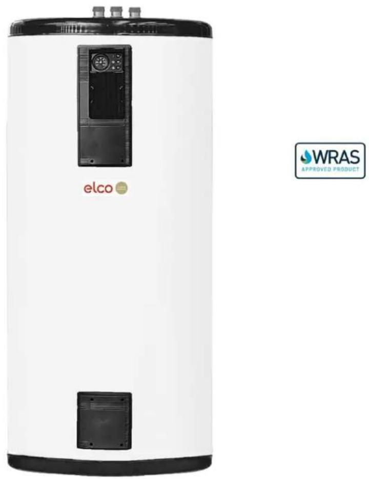
Installation and Operating Instructions

Index
Section Topic Page No
- Overview & Regulations ...... 3
- Technical data & dimensions 6
- Installation 9
- Connections 9
- Self-cleaning fluxes 10
- Hard water 10
- Unvented systems 10
- Expansion vessels pre-charge pressure 11
- Expansion vessel capacity 11
- Safety relief valves discharge pipes 11
- Tundish positioning and discharge 12
- Electrical installation 13
- Electrical connections – optional Immersion heaters ..... 16
- Typical installation schematics ..... 17
- Commissioning 19
- User instructions 20
- Regular maintenance 20
- Draining the cylinder 21
- Internal inspection. 22
- Spares. 23
- Notes 23
In compliance with Directive 2014/68/EU (PED) and the Regulations 812/2013 and 814/2013 issued by Directive 2009/125/EC (ErP - EcoDesign Requirements for Energy Related Products) and by Directive 2010/30/EC (Energy Labelling of Products), the technical and heat loss specifications together with the energy categories are written on the labels/technical sheets attached to the product. Such labels/technical sheets must be considered as an integral part of these instructions for use.
The Indirect Hot Water Cylinders have been tested in compliance with standard EN 12897. All Hot Water Storage Tanks are manufactured in accordance with Article 4.3 of PED and must not be CE marked. However the manufacturer guarantees the production quality in accordance with EN ISO 9001
1.1 Overview
The Gemini HSC range of high performance indirect hot water cylinders are WRAS approved for UK (dhw) systems. The calorifier range is constructed from two concentric cylindrical tanks (tank within a tank), a principle which provides many advantages over conventional coil or tube type calorifiers.
The Gemini HSC range is suitable for connection to open vented or unvented applications using the optional unvented kit which includes T&P valve, pressure relief valve, inlet water valve group (pressure reducing valve, non-return valve & strainer) and expansion vessel.
There are three models of calorifiers with storage capacities from 200 - 500 litres providing continuous hot water outputs of up to 1474 l/hr at a temperature rise of 50^ C.
The 316L stainless steel inner (secondary tank), which contains the domestic hot water, is corrugated and positioned within a mild steel outer (primary tank), through which the heating water is circulated. This arrangement ensures that the domestic hot water is efficiently and rapidly heated to provide a volume of hot water for a variety of domestic, commercial or industrial applications.
The inner tank is suspended within the outer tank, allowing freedom of movement such that it can flex freely preventing the adherence of performance reducing calcium scale to the inner walls.
The corrugations also create turbulence around the heating surface, preventing stratification and ensuring the elimination of cool zones within the tank.
The stainless steel construction provides corrosion resistance and significantly reduces the frequency of maintenance, avoiding the need for sacrificial anodes or powered anodes. For ease of maintenance, each tank is equipped with a top mounted inspection/cleaning port and has the facility to be supplied with a back-up electric immersion heater to provide nominal hot water supply during boiler shutdown.
Controls - each tank is equipped with an injection moulded control panel which houses a dial type thermometer, control thermostat, limit thermostat, immersion heater switch & indicator lamp and electric connection terminal rail.
The optional immersion heater is located in the primary tank below the inner (secondary) tank avoiding the potential for fouling by scale formation.
Insulation - the product is finished with injection moulded rigid PVC top and base covers, with an additional removable padded vinyl jacket surrounding a high density rigid polyurethane foam moulding providing insulation with excellent heat retention and minimised standing losses.
1.2 Regulations
Attention is drawn to the following documents for best practice:
Statutory Instruments
Water Supply (Water Quality England & Wales) Regulations 2016 - as amended
The Public Water Supplies (Scotland) Regulations 2014 - as amended
The Water Supply (Water Fittings) Regulation (Northern Ireland) 2009 - as amended
British Standards
BS 6880 Part 1, 2 & 3 Code of Practice for low temperature hot water heating systems of output greater than 45kW.
BS 7074 Part 1: Application, selection and installation of expansion vessels and ancillary equipment for sealed water systems.
Part 2: Code of Practice for low and medium temperature hot water heating systems.
BS 7671 Requirements for electrical installations. IET Wiring Regulations.
BS 8550 Guide for the auditing of water quality sampling
BS 8558 Guide to the design, installation, and maintenance of services supplying water for domestic use within buildings. Note: this document is complimentary to BS EN 806
BS 14743 Water conditioning equipment inside buildings. Softeners. Requirements for performance, safety and testing
BS EN ISO 4126-1 Safety devices for protection against excessive pressure. Safety valves.
BS EN 806 Specification for installations inside buildings conveying water for human consumption
Note: - BS6700- The Design, Installation, Testing and Maintenance of Services supplying water for domestic use within buildings. This document has been superseded by BS EN 806
Electrical Standards:- BS 3456 Part 201, EN 60335 Part 1
CP 342-2 Code of practice for centralised hot water supply. Buildings other than individual dwellings.
The Health and Safety Commission (HSC) approved code of practice and guidance document L8 - HSG274: Legionnaires disease. Technical Guidance.
CIBSE Publications
CIBSE Guide G Public Health Engineering
CIBSE TM13: Minimising the risk of Legionnaires' disease.
CIBSE Guide H Building Control Systems.
CIBSE Guide Energy Efficiency in Buildings.
CIBSE Commissioning Code B: 2002.
ICOM Publication - Water quality consideration for non- domestic hot water systems
Department of Health Technical Memorandum (HTM) 04-01: The control of Legionella, hygiene, 'safe' hot water, cold water and drinking water systems.
HTM 04-04 The Control of Legionella in Health Care Premises- Code of Practice: 2006
General Requirements
All connections to the local water main must comply with Water Supply (Water Fittings) Regulations 1999 (as amended). Compliance with the Regulations can be demonstrated by certification from notified body organisations such as WRAS or KIWA.
Unvented Systems
Building Regulations - use of unvented hot water storage systems with volumes exceeding 15 litres. G3 (England & Wales), P3 (Scotland) & P2 (Northern Ireland)
The unvented system components allows the storage vessel to be fed directly from the mains cold water supply, or from a booster pump set, without the need for feed and expansion tanks.
The unvented system components should be approved and comply with the Water Supply (Water Fittings) Regulations 1999 (as amended), including a suitably sized temperature and pressure (T&P) relief valve, which locates directly into the top portion of the storage vessel.
DISPOSAL
At the end of the technical life cycle of this product, all metal components must be delivered to operators authorised in the collection of metals for recycling, while all non-metal components must be delivered to suitably authorised agents. The disposal of products must be managed in accordance with local regulations and must never be managed as household waste.
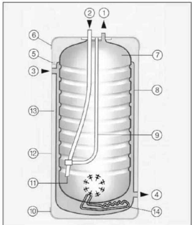
Fig 1 - Principle components
1 Hot water draw-off (vertical installation)
2 Cold feed (vertical installation)
3 Primary flow
4 Primary return
5 Primary air vent
6 Top moulding
7 Stainless steel domestic water tank
8 Primary vessel
9 Thermostat pocket & dip tube stay
10 Base moulding
11 Dip tube
12 Padded vinyl jacket
13 Rigid polyurethane foam insulation
14 Immersion heater (optional)
Secondary return connection not shown for clarity.
2 Technical data & dimensions
2.1.1 Dimensions
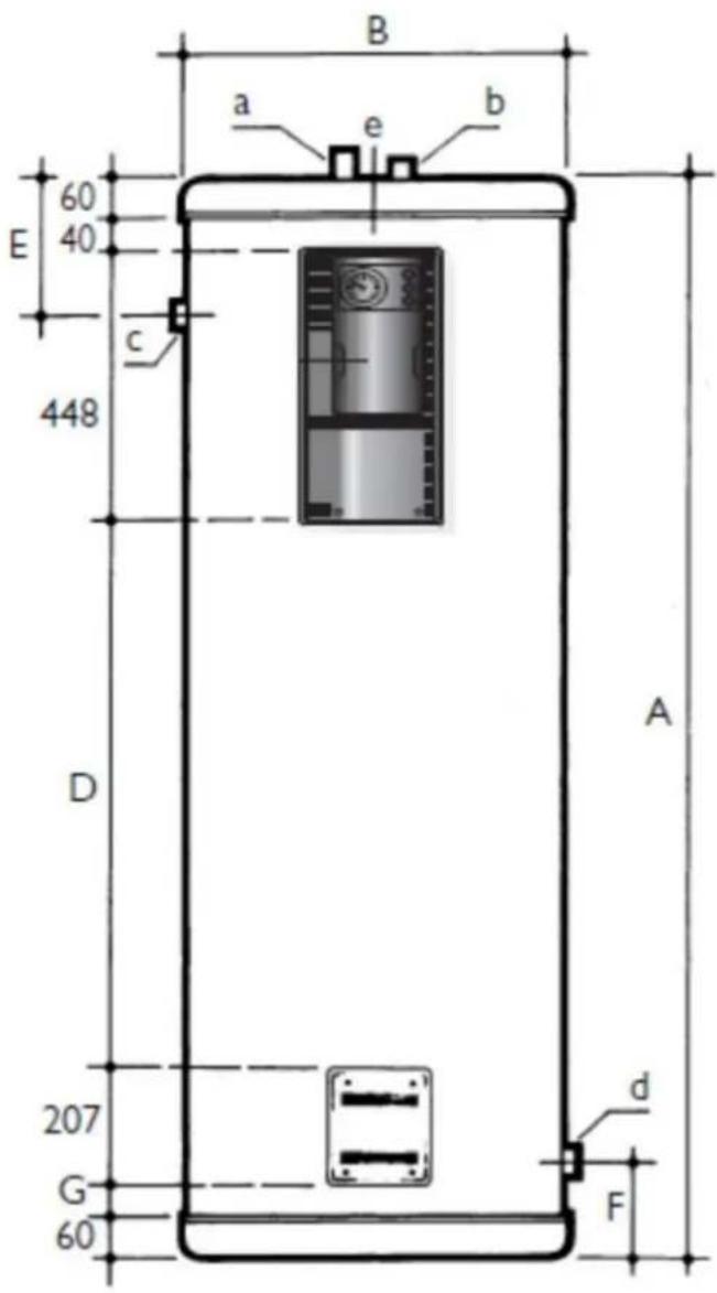
| MODEL | Units | A | B | D | E | F | G |
| HSC | |||||||
| 200 - i | mm | 1239 | 620 | 390 | 247 | 148 | 34 |
| 300 - l | mm | 1724 | 620 | 875 | 226 | 146 | 34 |
| 500 - l | mm | 1730 | 770 | 861 | 283 | 168 | 54 |
2.1.2 Connections - plan view
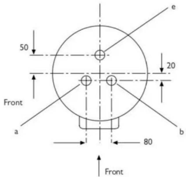
| MODEL | Primary Flow & Return c & d | DHW feed a** see note | DHW draw-off b** see note | Secondary Return e | |
| HSC | |||||
| 200 - i | 1" BSP - F | 34" BSP - M | 34" BSP - M | 34" BSP - M | |
| 300 - I | 1" BSP - F | 1" BSP - M | 1" BSP - M | 1" BSP - M | |
| 500 - I | 1 12" BSP - F | 1" BSP - M | 1" BSP - M | 1" BSP - M |
Note:
* Unvented applications require the necessary safety equipment: SRV/PRV (Safety relief & pressure reducing valve including check valve), external expansion vessel, tundish and a T&P (Temperature and Pressure) relief valve. These are supplied separately in the Unvented Kit.- refer to section 9.
** Open vented applications - a 11/2" * 1" reducing socket is supplied to increase the connection size of the DHW flow & return pipes.
2.1.3 Performance data
Note - performance of the unit will vary with operating conditions
| MODEL | Units | 200 - i | 300 - i | 500 - i |
| HSC | ||||
| DHW Capacity | L | 193 | 286 | 462 |
| Primary Capacity | L | 56 | 65 | 108 |
| Heating Surface | m^2 | 1.6 | 2.4 | 3.0 |
| Primary Flow 80°C & Return 70°C | ||||
| Heat Transfer | kW | 44 | 67 | 86 |
| Primary Circuit Pressure Drop | KPa | 1.7 | 5.4 | 3.3 |
| 10 min Peak Output @ 50°CT | L | 325 | 491 | 745 |
| 1st Hour Continuous Output @ 50°CT | L/h | 954 | 1448 | 1974 |
| Continuous Output @ 50°CT | L/h | 754 | 1148 | 1474 |
| Heat Up Time 10 - 60°C | min | 21 | 20 | 25 |
| Primary Flow 85°C & Return 65°C | ||||
| Heat Transfer | kW | 29.0 | 44.1 | 56.7 |
| Primary Circuit Pressure Drop | KPa | 0.4 | 1.3 | 0.8 |
| 10 min Peak Output @ 50°CT | L | 282 | 426 | 661 |
| 1st Hour Continuous Output @ 50°CT | L/h | 696 | 1056 | 1471 |
| Continuous Output @ 50°CT | L/h | 496 | 756 | 971 |
| Heat Up Time 10 - 60°C | min | 31 | 30 | 37 |
| Primary Flow 80°C & Return 60°C | ||||
| Heat Transfer | kW | 23.2 | 35.3 | 45.3 |
| Primary Circuit Pressure Drop | KPa | 0.4 | 1.3 | 0.8 |
| 10 min Peak Output @ 50°CT | L | 266 | 400 | 629 |
| 1st Hour Continuous Output @ 50°CT | L/h | 597 | 905 | 1277 |
| Continuous Output @ 50°CT | L/h | 397 | 605 | 777 |
| Heat Up Time 10 - 60°C | min | 39 | 37 | 46 |
| Maximum Operating Temperature Primary | °C | 90 | ||
| Maximum Operating Pressure Primary | bar | 3.0 | ||
| Maximum Operating Pressure Secondary | bar | 8.0 | ||
| Weight Empty/ Full | Kg | 78 / 327 | 109 / 460 | 151 / 721 |
3 Installation
3.1 Handling
Care should be taken when handling the Gemini cylinders to avoid damage to the casing and insulation.
3.2 Position
The position chosen for installation must be capable of supporting the unit when full of water and it is important to ensure that the unit is true and vertical with adequate access to water and electrical connections.
All models are suitable for horizontal installation, with a cradle being needed to support the tank (not Elco supply).
Important - any Gemini HSC tank installed in a horizontal plane must only be connected to an open vented system. Horizontally mounted Gemini tanks MUST NOT be installed on an unvented system!
The Gemini HSC range is not suitable for gravity circulation connection to a heating system.
4 Connections
Care must be taken when making pipe connections to the tank to avoid any undue loading of the connections. Pipework must be adequately supported to avoid any undue loading being applied to the cylinder and its connection points. All connections & valves must allow the complete disconnection and removal of local pipework to provide unimpeded access to the inspection access port on the top of the unit.
Note: ensure that any redundant tappings are capped off prior to filling the system.
When installing Gemini tanks in a horizontal installation, it is necessary to reverse the cold water inlet and hot water outlet connections
After a few days of operation it is good practice to check the integrity of all joints including the tightness of the inspection flange bolts on the top cover and the immersion heater flange.
It is recommended that long dead legs are avoided and that a secondary re-circulation system is installed where pipe runs are long.
All secondary connections are located on the top of the tank and are stainless steel. Care must be taken to ensure that there is no galvanic corrosion between the calorifier and the system pipework.
Note: - all models are supplied with 2 off 11/2" * 1" BSP FF sockets for adaption of the flow & return connections on open vented systems.
Refer to section 14 for system schematics
5 Self-cleaning fluxes
Excessive use of self-cleaning fluxes on copper pipework local to the calorifier should be avoided.
6 Hard Water
In known hard water areas the use of scale prevention measures is recommended. Ensure compatibility with stainless steel material. No warranty is provided for components such as immersion heaters that are damaged through sludge build up and lack of maintenance.
Water quality must be considered so as to ensure reliable operation of the system - refer to ICOM Publication - Water quality consideration for non-domestic hot water systems
7 Unvented Systems
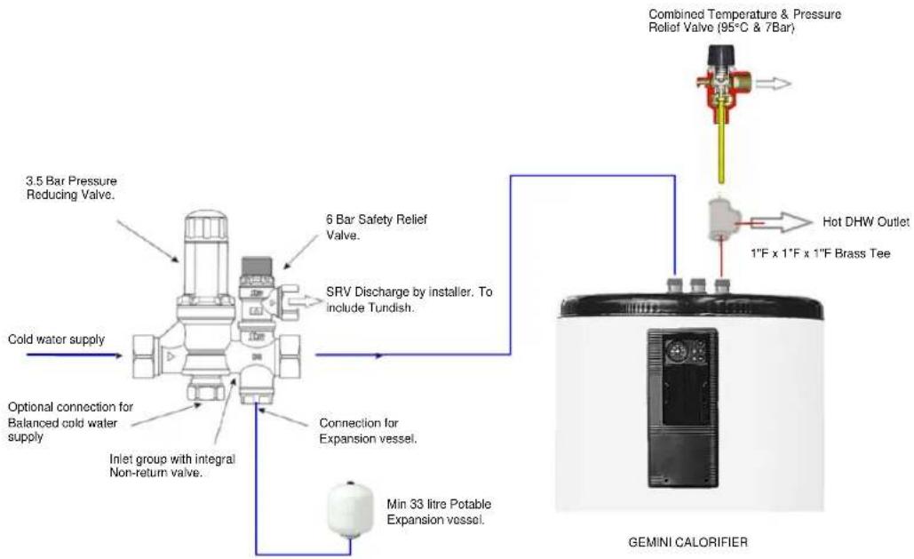
If the installation is to be of the “unvented” type, the cylinder will have been supplied with a kit of safety controls (loose) which must be installed (see Fig. 7 & Figs 14.2 & 14.3) so as to prevent the water temperature from exceeding 95°C.
The kit of parts includes as a minimum (see checklist of components - table 7.2) a suitably sized expansion vessel with air charge pre-set at 3.5bar, a pressure limiting valve set at 3.5bar, an expansion relief valve set at 6.0bar, a temperature & pressure relief valve set at 7bar & 95°C, a core block manifold assembly with integral non return valve and a tundish.
The components must be installed as shown in Fig 7.1. There must be no valves installed between the calorifier and the connection to the expansion relief valve. The connections provided for the connection of the T&P valve and the ER valve must not be used for any other purpose. The mains water supply pressure must not exceed 25bar.
flowchart
graph TD
    A["Cold water supply"] --> B["3.5 Bar Pressure Reducing Valve"]
    B --> C["6 Bar Safety Relief Valve"]
    C --> D["SRV Discharge by installer. To include Tundish."]
    D --> E["Connection for Expansion vessel"]
    E --> F["Min 33 litre Potable Expansion vessel"]
    F --> G["Optional connection for Balanced cold water supply"]
    G --> H["Inlet group with integral Non-return valve"]
    H --> I["Combined Temperature & Pressure Relief Valve (95°C & 7Bar)"]
    I --> J["Hot DHW Outlet"]
    J --> K["1"F x 1"F x 1"F Brass Tee"]
    K --> L["GEMINI CALORIFIER"]
Figure 7.1 - Unvented valve group – Installation Guide
| Model | 200 - i | 300 - i | 500 - i |
| Unvented kits Elco part no. | Kit-100-2 | Kit 100 | Kit 100 |
| Component part | 1" to 3⁄4" Reducer 3 No | ||
| Component part | T&P valve 1"BSP x 28mm 7 Bar 95°C | ||
| Component part | 33/35 litre expansion vessel vertical white c/w with bracket. 3 Bar charge. | ||
| Component part | Compact Inlet control 3.5 Bar PRV - 6 Bar ERV - NRV | ||
| Component part | 22x28mm Straight Tundish (black plastic) | ||
| Component part | 1" x 1 1⁄4" FBSP Straight Epoxy M/S Tundish | ||
| Component part | 1" F Equal Tee | ||
Table 7.2 - Unvented kit components supplied by ELCO Heating Solutions are suitable for use on domestic hot water system and are either WRAS or KIWA certified.
8 Expansion Vessel pre-charge Pressure
It is the responsibility of the installer to check the air pre-charge pressure before installation and adjust as necessary to 3.5bar.
9 Expansion Vessel Capacity
The capacity of the expansion vessel supplied as part of the unvented kit, is nominally sized to accommodate the capacity of the cylinder with which it was supplied plus a nominal system pipework volume of approximately 17.5% of the cylinder capacity. If the system pipework capacity exceeds the allowance described above, then appropriately sized additional potable water expansion vessels will need to be obtained and installed.
10 Safety Relief Valve Discharge Pipes
It is a requirement of the Building Regulations that any discharge from an unvented system is conveyed safely to a point that is visible but will not constitute a hazard or danger to persons in or about the building.
It is the responsibility of the installer to supply and install discharge pipes and suitable tundishes, in accordance with the requirements of the Building Regulations.
11 Tundish Positioning & Discharge
The tundish should be vertical, located in the same space as the unvented hot water storage system and be fitted as close as possible and within 500mm of the safety
device (i.e. the temperature pressure relief valve) and must be away from any electrical device.
The discharge pipe from the tundish should terminate in a safe place where there is no risk to persons in the vicinity of the discharge, according to Building Regulation G3.
Note: The discharge will consist of scalding water and steam. Asphalt, roofing felt and non-metallic rain water goods may be damaged by such discharges. Where children may play or otherwise come in contact with discharges, a wire cage or similar guard must be positioned to prevent contact whilst maintaining visibility.
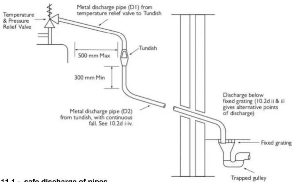
Figure 11.1 - safe discharge of pipes
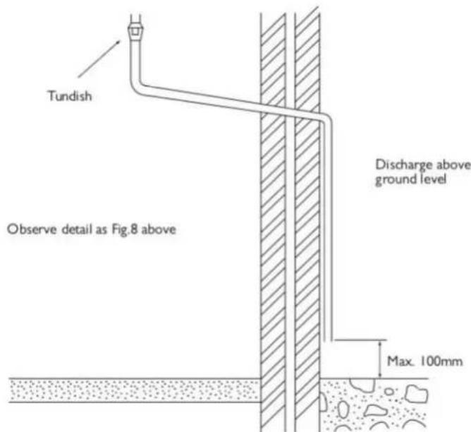
Figure 11.2 - safe discharge of pipes
12 Electrical installation
Wiring should be carried by a competent electrician in accordance with the current edition of the IEE Regulations.
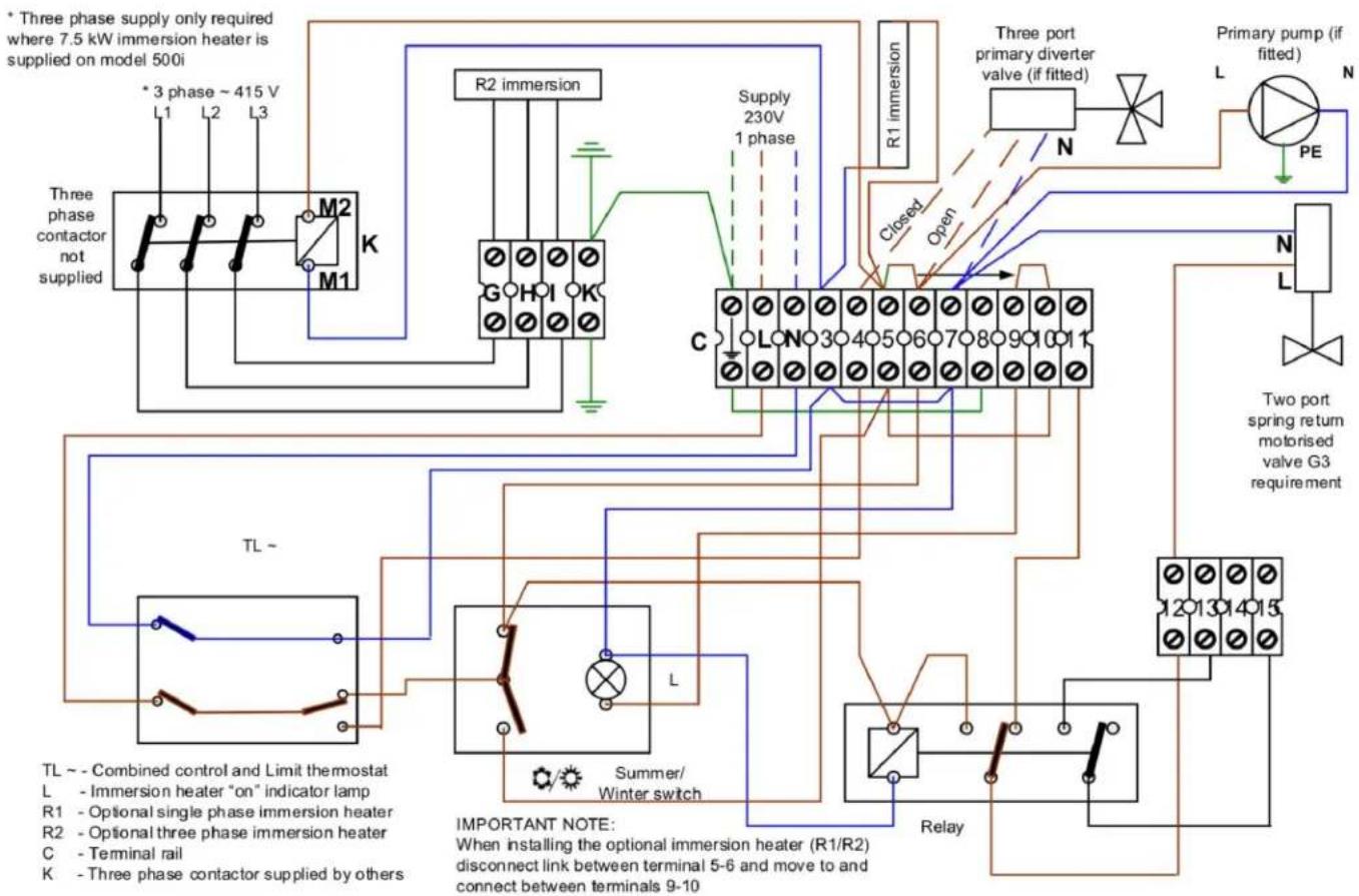
Thermostats within the control panel are rated at 2.5 A / 230V. Should electrical loads exceed this rating, a suitably rated contactor or relay must be interposed. An appropriately rated isolator and fuses should be installed to protect the control and load circuits.
For wiring of external motorised valves into the control panel, refer to figure 12 below.
flowchart
graph TD
    A["Three phase contactor not supplied"] --> B["M1"]
    B --> C["M2"]
    C --> D["R2 immersion"]
    D --> E["Supply 230V 1 phase"]
    E --> F["C"]
    F --> G["Three port primary diverter valve (if fitted)"]
    G --> H["N"]
    H --> I["Primary pump (if fitted)"]
    I --> J["L"]
    J --> K["PE"]
    K --> L["N"]
    L --> M["L"]
    M --> N["Two port spring return motorised valve G3 requirement"]
    O["TL ~ Combined control and Limit thermostat"] --> P["L - Immersion heater "on" indicator lamp"]
    Q["R1 - Optional single phase immersion heater"] --> R["R2 - Optional three phase immersion heater"]
    S["R2 - Terminal rail"] --> T["K - Three phase contactor supplied by others"]
    U["L Summer/Winter switch"] --> V["Relay"]
    W["Important Note: When installing the optional immersion heater (R1/R2) disconnect link between terminal 5-6 and move to and connect between terminals 9-10"] --> X["Relay"]
    Y["TL ~"] --> Z["Combined control and Limit thermostat"]
    AA["RL"] --> AB["Implied from TL ~"]
    AC["RL"] --> AD["Replied from Summer/Winter switch"]
    AE["RL"] --> AF["Replied from Relay"]
Figure 12 - wiring diagram
Important Note - in the event of an immersion heater being fitted (in the primary system), consideration should be given to system isolation in the event that the immersion heater is in use. The use of a two port isolating valve is acceptable, as detailed in the wiring diagram above. Failure to do so may compromise immersion heater performance.
12.1 Control panel
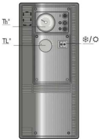
Figure 12.1 - control panel
Th Thermometer
TL Combined Control & Limit Thermostat

Summer/Winter Switch
Summer setting gives operation via immersion heater (optional extra) if fitted.
12.2 Electrical connections
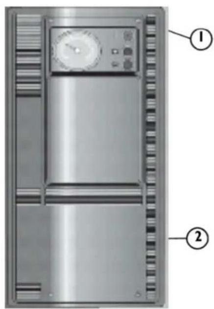
Figure 12.2 - remove the control panel
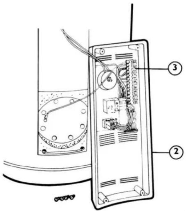
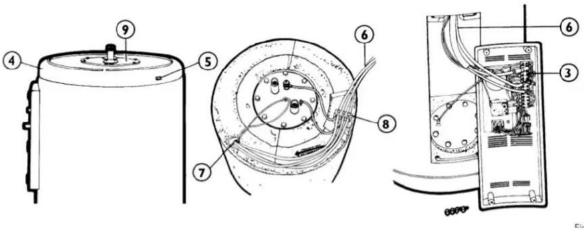
Figure 12.3 - Installing the control panel wiring
Remove the 4 off fixing screws (1) retaining the control panel - see fig 12.2
Carefully rotate the control panel (2) to expose the electrical connection terminal rail (3)
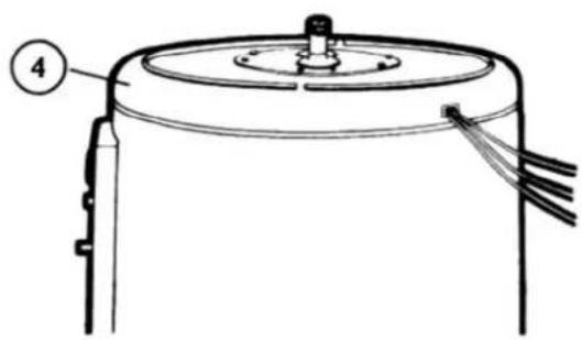
Carefully cut out the cable entry aperture (5) on the top cover (4) - see fig 12.3
Lift up the top cover (4), whilst removing the cleaning access cover panel (9)
Route appropriately sized cables (multi-strand flex only) (6) through the aperture (5), through the cable clamp (8) and carefully guide the cables down through the cable tube (7) to terminate at the control panel rear.
Make the necessary electrical connections to the terminal rail (3) - refer to figs 12 & 12.2
Refit the control panel (2) to the calorifier using. Screws (1). Ensure that the cables (6) are routed correctly with sufficient slack to allow future access to the rear of the control panel (2) and securely retain the cables under the clamp (8).
Refit the top cover (4) and cleaning access cover panel (9).
12.3 Reset the limit thermostat
In the event that the system overheats, the limit thermostat will operate resulting in the safe shut-down of the system, requiring a manual reset.
Note: - reset of the limit thermostat must be carried out by a competent person
1 Isolate the electrical supply to the calorifier and remove the control panel - see section 12.2
2 Remove the thermostat knob by pulling it off the thermostat spindle, exposing the fixing screws. Remove the fixing screws and allow the thermostat to fall away from the control panel.
3 Press the reset pin marked "S" on the thermostat body (adjacent to the spindle).
4 Re-assemble the control panel in reverse order.
13 Electrical connections for optional immersion heaters
| Model | Units | 200 - i | 300 - i | 500 - i |
| Immersion heater rating - 230v | kW | 2.5 | 2.5 | 2.5 |
| Recovery time @ 50°C | Hrs | 4.5 | 6.7 | 10.8 |
| Option | ||||
| Immersion heater rating - 415v | kW | n/a | n/a | 7.5 |
| Recovery time @ 50°C | Hrs | n/a | n/a | 3.6 |
Table 13.1 - immersion heaters
It is important to ensure that only immersion heaters supplied by Elco, are used for installation into the Gemini tank.
Installation - the immersion heater is fitted to the primary tank underneath the stainless steel DHW tank. Take care in fitting the immersion heater flange and gasket. Check the immersion heater joint to the tank ensuring that there are no leaks.
IMPORTANT - due to the design of the tank, the location of the immersion heater being in the primary tank and the extremely low resistance of the primary tank, consideration must be given to isolate the primary system in the event no heating requirement. This can be achieved by using two port or three port electrical valves as shown in figures 12, 14.2 & 14.3. The consequence of not considering this could result in excessive use of the immersion heater from losing heat into the primary system.
OPTION - A factory fitted option of a 7.5kW 3phase, 415V immersion heater is available to provide enhanced operation for the model 500-i only
Note: this option is not available on models 200-i or 300-i.
Recovery time at 50°C Δt detailed in table 13.1
NOTE a Three Phase contactor will need to be installed if using this option (NOT Elco SUPPLY).
Wiring - Ensure that the electrical connections have been correctly made - refer to Fig 12 and that the supply is of adequate rating with a correctly sized fuse.
Operation - Ensure that the element is immersed in the water as failure to fill the primary circuit will result in ‘burn out’ of the element.
Set the control thermostat to the required setting.
Set the summer/winter switch to the summer position
Turn on the electrical supply at the fused isolator.
Maintenance - The immersion heater must be electrically isolated before removing the terminal cover. Periodically inspect the element to check for any deposit build up on the element. This can be achieved by isolating the tank from the primary circuit and draining down the primary tank through the drain valve, ensuring that the manual primary air vent located adjacent to the primary flow connection, is open.
14 Typical Installation Schematics
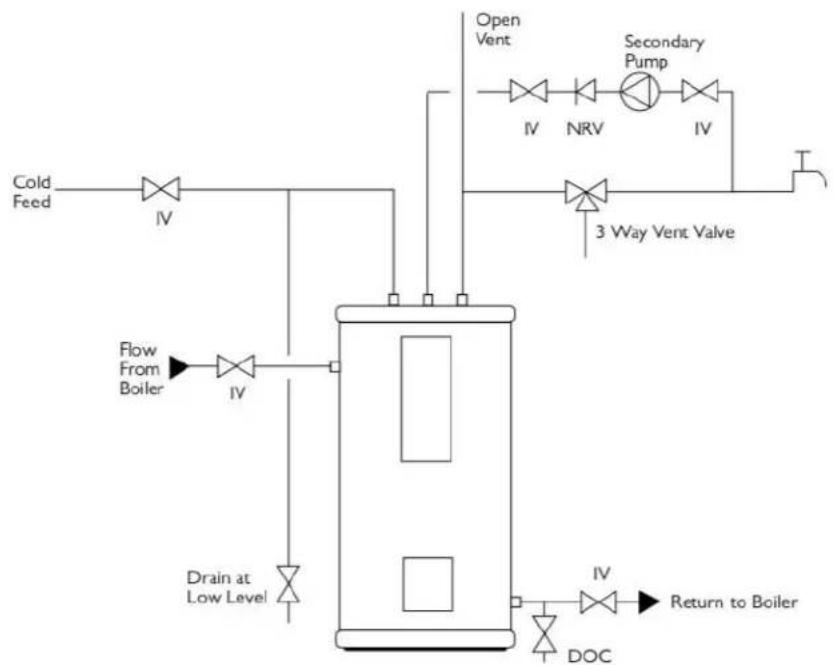
flowchart
graph TD
    A["Cold Feed"] --> B["IV"]
    B --> C["Drain at Low Level"]
    C --> D["Flow From Boiler"]
    D --> E["IV"]
    E --> F["3 Way Vent Valve"]
    F --> G["IV"]
    G --> H["Return to Boiler"]
    I["Open Vent"] --> J["IV"]
    J --> K["NRV"]
    K --> L["IV"]
    L --> M["Secondary Pump"]
    M --> N["IV"]
    N --> O["Return to Boiler"]
    P["DOC"] --> Q["IV"]
Figure14.1 - Typical Open vented calorifier schematic
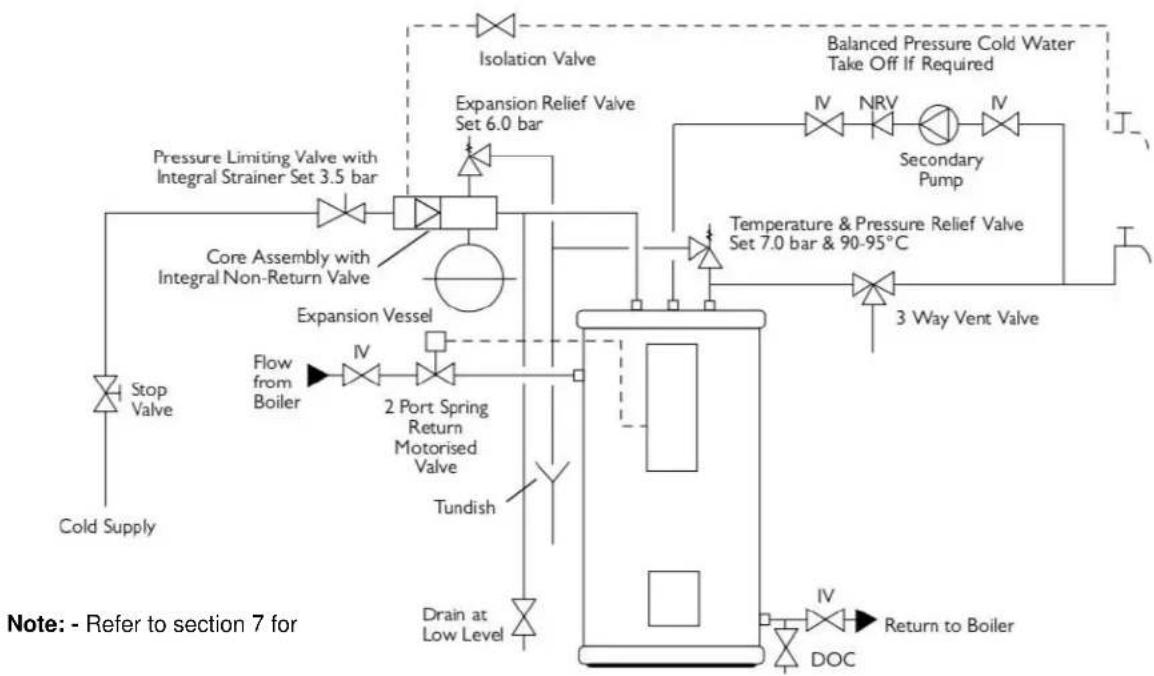
flowchart
graph TD
    A["Cold Supply"] --> B["Stop Valve"]
    B --> C["Flow from Boiler"]
    C --> D["2 Port Spring Return Motorised Valve"]
    D --> E["Tundish"]
    E --> F["Expansion Vessel"]
    F --> G["Expansion Relief Valve Set 6.0 bar"]
    G --> H["Isolation Valve"]
    H --> I["Balance Pressure Cold Water Take Off If Required"]
    I --> J["Secondary Pump"]
    J --> K["3 Way Vent Valve"]
    K --> L["Return to Boiler"]
    M["Pressure Limiting Valve with Integral Strainer Set 3.5 bar"] --> N["Core Assembly with Integral Non-Return Valve"]
    N --> O["Expansion Vessel"]
    O --> P["Tundish"]
    P --> Q["Drain at Low Level"]
    Q --> R["Return to Boiler"]
    S["IV"] --> T["DOC"]
    U["IV"] --> V["Return to Boiler"]
Figure14.2 - Typical Unvented calorifier schematic
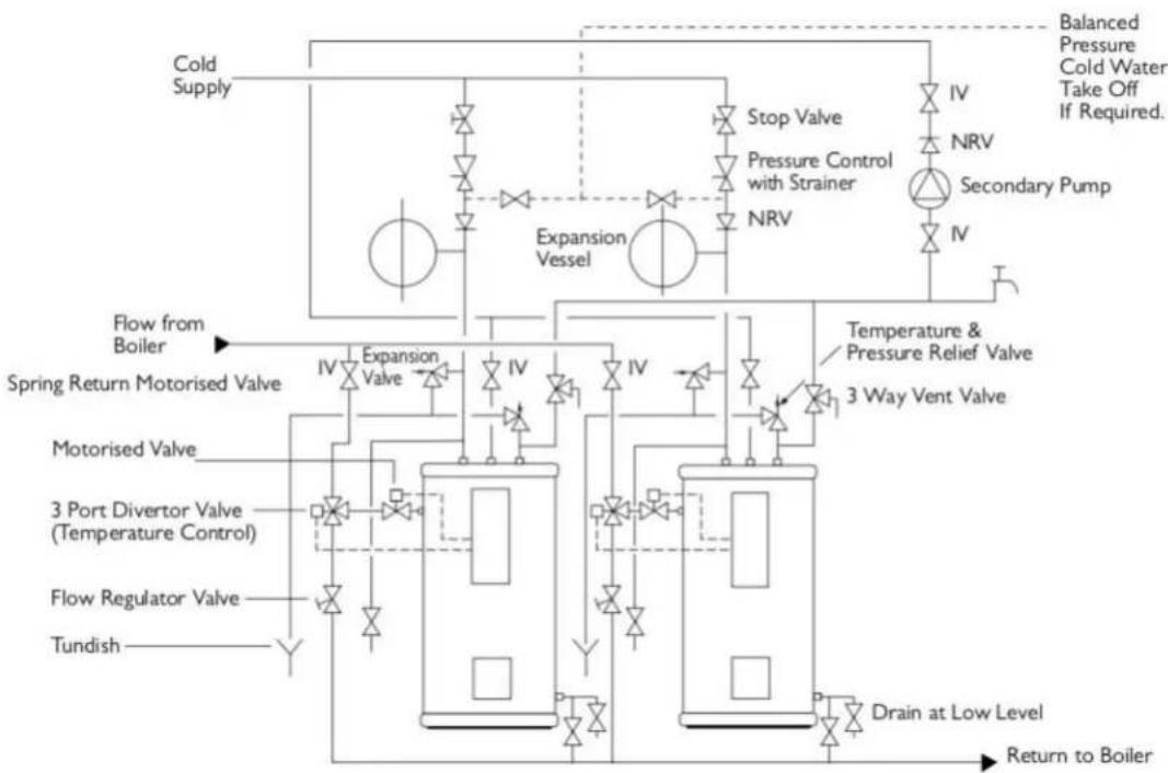
flowchart
graph TD
    A["Cold Supply"] --> B["Expansion Vessel"]
    B --> C["Stop Valve"]
    C --> D["NRV"]
    D --> E["Secondary Pump"]
    E --> F["IV"]
    F --> G["NRV"]
    G --> H["Balance Pressure Cold Water Take Off If Required."]
    I["Flow from Boiler"] --> J["Spring Return Motorised Valve"]
    K["3 Port Divertor Valve (Temperature Control)"] --> L["Expansion Valve"]
    M["Flow Regulator Valve"] --> N["Tundish"]
    O["3 Way Vent Valve"] --> P["Temperature & Pressure Relief Valve"]
    Q["Drain at Low Level"] --> R["Return to Boiler"]
    S["Motorised Valve"] --> T["Expansion Valve"]
    U["3 Port Divertor Valve"] --> V["Expansion Valve"]
    W["Flow Regulator Valve"] --> X["Tundish"]
Figure 14.3 - Typical unvented multiple calorifier schematic
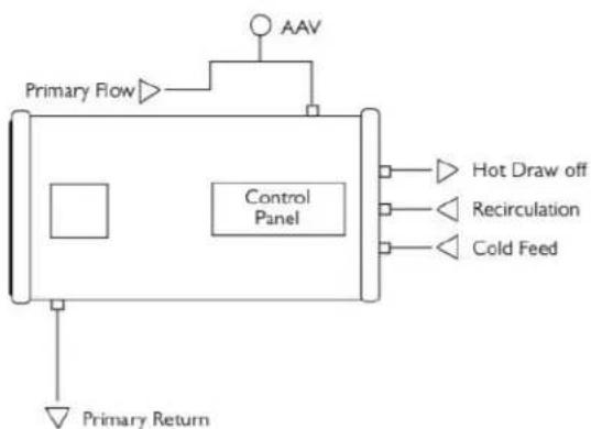
flowchart
graph TD
    A["Primary Flow"] --> B["Control Panel"]
    B --> C["Hot Draw off"]
    B --> D["Recirculation"]
    B --> E["Cold Feed"]
    F["AAV"] --> B
    G["Primary Return"] --> B
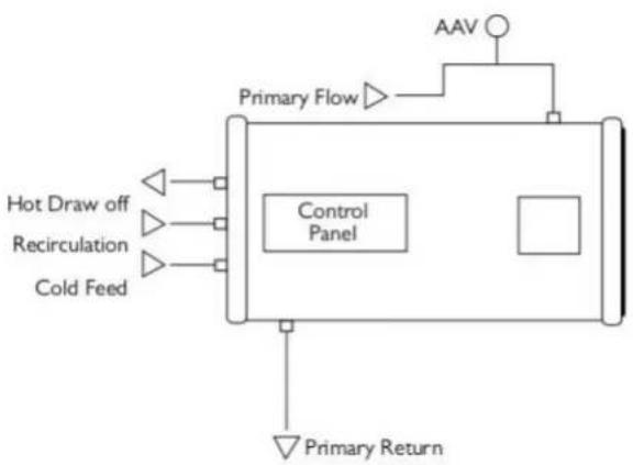
Note: - for l/h horizontal installations, the removable dip tube assembly plate must be rotated 180. from its original position, so that the connection marked "cold water inlet" is at the top. The hot water outlet must then be connected to the top connection and the cold water feed to the bottom connection.
Where an immersion heater is to be installed on a l/h installation
Figure 14.4 - Right hand horizontal installation
When making a horizontal installation it is necessary to reverse the cold water inlet and hot water outlet (secondary) connections.
Regardless of r/h or l/h installation, the control panel must always face the side and the primary flow and return connections must always be top & bottom dead centre respectively
Figure 14.4 - Right hand horizontal installation
flowchart
graph TD
    A["Hot Draw off"] --> B["Control Panel"]
    C["Recirculation"] --> B
    D["Cold Feed"] --> B
    B --> E["Primary Return"]
    F["AAV"] --> G["Primary Flow"]
    G --> B
issue Date March 2019
15 Commissioning
It is important to ensure that all pipework is flushed to avoid damage to valves from debris.
-
If the installation is unvented, before filling the system with water, check the air pressure in the potable water expansion vessel and adjust as necessary to a nominal 3.5bar.
-
If the pressure regulating valve supplied with the unvented kit is an adjustable type, ensure that the setting is limited at a maximum of 3.5bar.
-
Ensure all drain valves are closed. The secondary (inner) tank must be filled first. Check and clean the line strainer.
-
Open a tap at the furthest distance from the cylinder.
-
Open the isolation valve in the water supply to the cylinder, allowing the cylinder to fill and air to be expelled from the system via the open tap. Continue to allow water to flow from the open tap for some minutes until the water flows freely without air and dirt particles.
-
Check/operate each tap in turn on the system to ensure that the pipework is fully vented of air and dirt/installation debris is flushed from the installation.
-
Visually check all joints for water tightness.
-
Check the operation of all relief valves by manually opening the valves via the attached levers and ensuring that the discharged water clears freely via the tundish and the discharge pipework. Check that the flow ceases completely when the levers are released.
Immersion Heater
-
Turn on the power supply to the immersion heater/s and allow the cylinder to heat up.
-
Check operation of control thermostat.
-
Visually check all joints for water tightness.
-
Check that no water is/has issued from the thermal and pressure relief valve or expansion relief valve.
Primary (outer) tank
Warning - failure to observe the correct filling sequence (inner tank first) may lead to irreparable damage to the calorifier due to pressure.
-
Manually open the motorised valve if fitted (not Elco supply) in the primary circuit and fill, flush and vent the primary tank observing any instructions from the boiler manufacturer.
-
Turn on the primary heat source (boiler) and allow the cylinder to heat up.
Note: - failure to properly vent the primary circuit, will result in circulation noise and poor performance of the unit.
-
Check operation of control thermostat and motorised valve
-
Visually check all joints for water tightness.
-
Check that no water is/has issued from the thermal and pressure relief valve or expansion relief valve.
16 User Demonstration
- Important if water is seen to issue from either the thermal and pressure relief valve or expansion relief valve then turn off the electricity supply to immersion heater and turn off the heating boiler. Do not turn off the water supply. Immediately contact a competent installer of unvented hot water systems for assistance.
2 Do not tamper with any safety relief valve fitted to the system, if a fault is suspected contact a competent installer. - Temperature control – immersion heaters have an adjustable thermostat with settings between 50 and 80°C. Isolate electricity supply before removing the controls cover to make any adjustment.
- Temperature control – A combined control & limit thermostat is factory fitted to the controls panel, manually adjustable between 30 and 60°C. Adjust to the required setting. The manually resettable limit thermostat is set at 90°C.
- Be aware that it is quite normal for a surge in flow and pressure to occur on initial opening of a hot water tap on a unvented hot water system and does not indicate a fault.
17 Regular Maintenance
To ensure safe and continued performance of the water heater it is a requirement that the unit should be regularly maintained and only genuine spare parts from Elco Heating should be used.
Maintenance should be carried out at intervals not exceeding 12 months by a competent installer
In hard water areas, the inner tank should be periodically cleaned of any accumulated scale.
The operation of thermal and pressure relief valve and expansion relief valve should be checked by manually operating via the test levers; water should flow freely through the tundish and the valve should reseat when the lever is released. Warning the water discharged may be very hot. The strainer in the water supply should be checked and cleaned during maintenance operations.
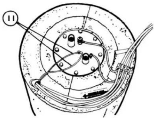
17.1 Replacement of Immersion Heater
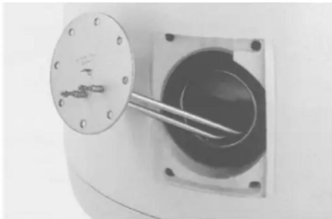
In order to replace the electric immersion heater, it is necessary to drain the primary side only - refer to section 18.
1 Isolate the electrical supply and remove the immersion heater cover panel
2 Disconnect the electrical connections from the immersion heater noting the location.
natural_image
Close-up of a metallic mechanical component with a circular flange and central rod, mounted on a square base (no visible text or symbols)3 Remove the fixing bolts from the circumference of the mounting plate. Withdraw the immersion heater element to the front and then to the side. Remove and discard the gasket.
4 Insert new element complete with new gasket.
5 Secure the immersion heater by tightening the bolts evenly using opposite - opposite sequence.
Figure 17.1 - remove the immersion heater
6 Re-fill and vent the primary side and ensure water tightness of the gasket joint.
7 Re-connect the electrical connections and re-fit the cover panel.
18 Draining the Cylinder
This operation should only be undertaken by a competent person as water drained from the system may be very hot and under pressure.
WARNING: Irreparable damage may occur to the cylinder body if a vacuum is created in the cylinder during emptying by failing to open the manual vent valve.
If it is required to drain the secondary (inner) tank the following procedure must be followed to avoid damage to the unit.
1 Isolate and drain the primary (outer) tank ensuring that the manual primary air vent (located adjacent to the primary flow in connection) is opened whilst draining.
2 Isolate the domestic water cold feed and open the hot water draw-off to atmosphere.
3 Open the low level drain valve (to be fitted by installer) and the inner tank will syphon drain. Vertically installed tanks will drain 80% of the tank capacity. The remainder will require removal by a hose and pump. Horizontally installed tanks will drain 50% of the tank capacity through any of the system connections in the centreline. The remainder will require removal by a hose and pump.
4 For re-filling, close the drain valves and vents and follow the procedure as detailed in section 15
natural_image
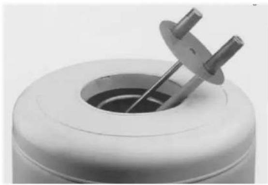
Close-up of a white cylindrical mechanical component with a metallic tool inserted into a circular opening (no visible text or symbols)Figure 19.1 - remove the dip tube assembly
natural_image
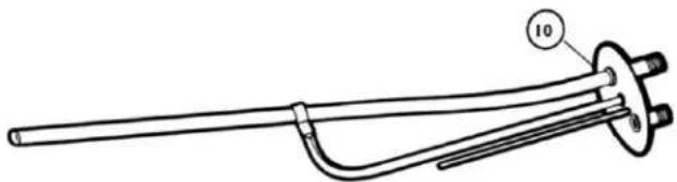
Technical line drawing of a mechanical or electrical component with a central flange and a curved handle (no text or symbols)Figure 19.2 - dip tube assembly
natural_image
Technical line drawing of a cylindrical device with a central hub and cable connectors (no text or symbols)Figure 19.3 - access to cleaning port
19 Internal inspection (secondary)
The Gemini HSC range is designed to allow internal inspection and cleaning of the tank.
1 Isolate and drain the DHW tank as described in section 18
2 Disconnect and remove all secondary pipe work, so as to provide full access for removal of the tube plate & dip tube assembly.
3 Lift up and move to one side the plastic top moulding and carefully withdraw the thermostat capillaries and sensor bulbs from the pocket in the tube plate.
4 Remove the bolts from the circumference of the flange and lift away the flange plate
5 Carefully lift away the dip tube assembly.
6 Re-assemble in reverse order fitting a new tube plate gasket
7 Refill the tank observing the fill procedure detailed in section 15
a Exploded view
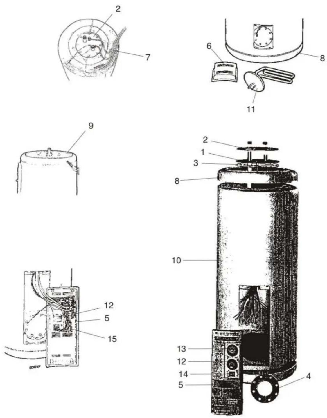
b Spares part numbers
| Key | Description | Model | 200-i | 300-i | 500-i |
| Part No. | |||||
| 1 | Connection port flange | 148014032 | √ | √ | |
| Connection port flange | 006849848 | √ | √ | ||
| 2 | Connection port counter flange | 148014038 | √ | ||
| Connection port counter flange | 006849848 | √ | |||
| 3 | Connection port gasket | 148014040 | √ | √ | √ |
| 4 | Inspection port gasket | 148014041 | √ | √ | √ |
| 5 | Control panel assembly | 006849849 | √ | √ | √ |
| 6 | Inspection port cover assembly | 148010006 | √ | √ | √ |
| 7 | Wiring harness sub assembly | 148016028 | √ | √ | √ |
| 8 | Top & Base cover | 006849851 | √ | √ | |
| Top & Base cover | 006849852 | √ | |||
| 9 | Top panel inner cover | 006849853 | √ | √ | √ |
| 10 | Padded outer cover | 006849857 | √ | ||
| Padded outer cover | 006849858 | √ | |||
| Padded outer cover | 006849859 | √ | |||
| 11 | Right hand immersion heater | 148016007 | √ | √ | √ |
| Left hand immersion heater | 148016016 | √ | √ | √ | |
| 12 | Control thermostat - IMIT | 147037034 | √ | √ | √ |
| Control thermostat - T&G | 147037021 | √ | √ | √ | |
| 13 | Thermometer - IMIT | 147037051 | √ | √ | √ |
| Thermometer - T&G | 147037052 | √ | √ | √ | |
| 14 | Double pole switch - Summer/Winter | 148036000 | √ | √ | √ |
| 15 | Relay plus base | 148016029 | √ | √ | √ |
21 Notes
This section is left intentionally blank for notes:


ELCO UK
3 Juniper West, Fenton Way, Southfields Business Park, Basildon, Essex SS15 6SJ
Tel: 01268 547600 Fax: 01268 88250
www.elco.co.uk
This publication is issued subject to alteration or withdrawal without notice. The illustrations and specifications are not binding in detail. All offers and sales are subject to the Company's current terms and conditions of sale.
- Stainless Steel Tank in Tank Indirect Hot Water Cylinders
- Index
- Section Topic Page No
- Overview
- Regulations
- Statutory Instruments
- British Standards
- CIBSE Publications
- General Requirements
- Unvented Systems
- DISPOSAL
- Technical data & dimensions
- Dimensions
- Connections - plan view
- Note:
- Performance data
- Installation
- Handling
- Position
- Connections
- Self-cleaning fluxes
- Hard Water
- Unvented Systems
- Expansion Vessel pre-charge Pressure
- Expansion Vessel Capacity
- Safety Relief Valve Discharge Pipes
- Tundish Positioning & Discharge
- Electrical installation
- Control panel
- Electrical connections
- Reset the limit thermostat
- Electrical connections for optional immersion heaters
- Table 13.1 - immersion heaters
- Typical Installation Schematics
- Commissioning
- Immersion Heater
- Primary (outer) tank
- User Demonstration
- Regular Maintenance
- Replacement of Immersion Heater
- Draining the Cylinder
- Internal inspection (secondary)
- Notes
- This section is left intentionally blank for notes:
- ELCO UK
Brand : Elco
Model : GEMINI HSC
Category : Boiler