Sharpy C61375 - Lighting Claypaky - Free user manual and instructions
Find the device manual for free Sharpy C61375 Claypaky in PDF.


| Brand | Claypaky |
| Model | Sharpy C61375 |
| Product Type | Moving Head Spotlight |
| Category | Lighting |
| Lamp Type | 189W Discharge Lamp |
| Power Supply | 100-240 V AC, 50/60 Hz |
| DMX Channels | 17 (Standard) / 20 (Vector) |
| Pan Range | 540° |
| Tilt Range | 270° |
| Color Wheel | Fixed colors with linear movement option |
| Gobo Wheel | 17 static gobos with shake effect |
| Prism | Insertable with rotation |
| Frost | Variable frost filter |
| Focus | Motorized |
| Dimmer | 0-100% with adjustable curve |
| Strobe | 1-12 flashes/sec, random strobe |
| Control Protocol | DMX512, Art-Net (optional) |
| Display | Backlit LCD with auto-dim |
| Menu Lock | Yes (4-digit password) |
| Cooling | Fan-cooled (3 fans) |
| Maintenance | Annual service, periodic cleaning |
| Safety | Safety cable attachment point |
| Optional Accessories | Heat screen filter |
| Manual Languages | English, French, German, Spanish, Italian |
Frequently Asked Questions - Sharpy C61375 Claypaky
User questions about Sharpy C61375 Claypaky
0 question about this device. Answer the ones you know or ask your own.
Ask a new question about this device
Download the instructions for your Lighting in PDF format for free! Find your manual Sharpy C61375 - Claypaky and take your electronic device back in hand. On this page are published all the documents necessary for the use of your device. Sharpy C61375 by Claypaky.
USER MANUAL Sharpy C61375 Claypaky
natural_image
Line drawing of a mechanical optical device with no visible text or symbols| INDEX | |
| Page | Contents |
| 2 | Safety Information |
| 3 | Unpacking and preparation |
| 4 | Installation and start-up |
| 5 | Control panel |
| 7 | Menu setting |
| 14 | Maintenance |
| 21 | Optional accessories |
| 22 | Dimensions |
| 22 | Cause and solution of problems |
| 23 | Channel functions |
Congratulations on choosing a Claypaky product!
We thank you for your custom.
Please note that this product, as all the others in the rich Claypaky range, has been designed and made with total quality to ensure excellent performance and best meet your expectations and requirements.
Carefully read this instruction manual in its entirety and keep it safe for future reference. It is essential to know the information and comply with the instructions given in this manual to ensure the fitting is installed, used and serviced correctly and safely.
Claypaky disclaims all liability for damage to the fitting or to other property or persons deriving from installation, use and maintenance that have not been carried out in conformity with this instruction manual, which must always accompany the fitting.
Claypaky reserves the right to modify the characteristics stated in this instruction manual at any time and without prior notice.
SAFETY INFORMATION
EN
SAFETY INFORMATION
IMPORTANT: Claypaky recommends you carefully read and keep the safety information on this product, also available in digital format at the following link:
www.claypaky.com
Ref: [FIS010 – Safety Information Sharpy]
IT
Rif: [FIS010 - Safety Information Sharpy]
DE
Ref: [FIS010 - Safety Information Sharpy]
ES
Ref: [FIS010 - Safety Information Sharpy]
FR
CONSIGNES DE SÉCURITÉ
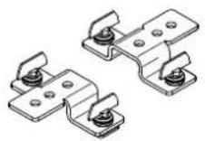
2 x 183102/805
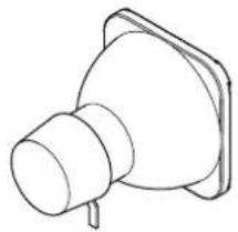
Lamp 189W (fitted into projector)
natural_image
Line drawing of a mechanical component with a flanged base and cylindrical top (no text or symbols)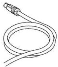
natural_image
Line drawing of a coiled cable with a connector (no text or symbols)Packing contents - Fig. 1
3
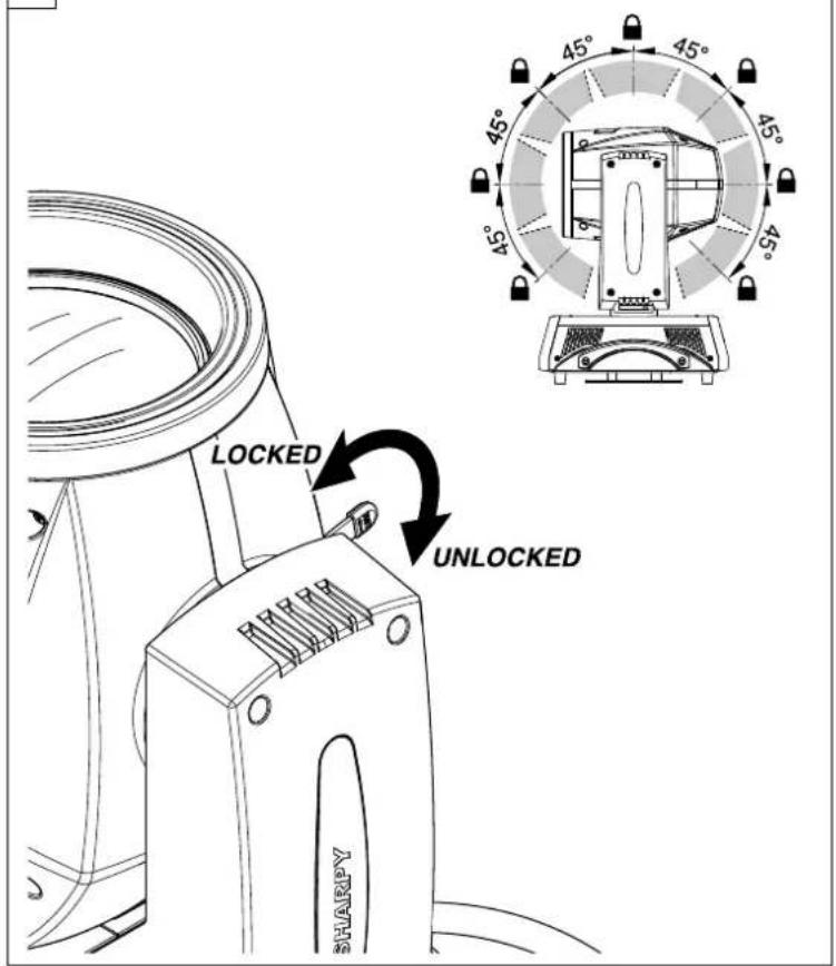
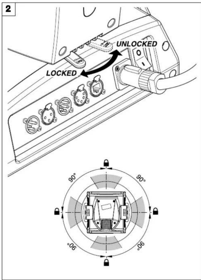
PAN Mechanism Lock and Release (every 90°) - Fig. 2
TILT Mechanism Lock and Release (every 45°) - Fig. 3
4
natural_image
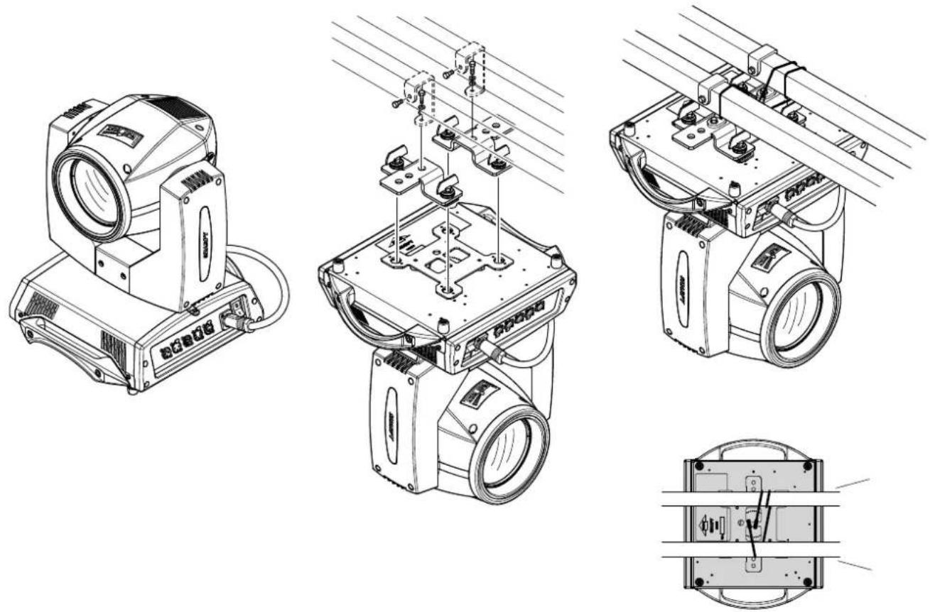
Technical line drawings of four different types of optical or mechanical components, including a projector and a multi-view assembly (no text or symbols present)Installing the projector - Fig. 4
The projector can be installed on the floor resting on special rubber feet, on a truss or on the ceiling or wall.
WARNING: with the exception of when the projector is positioned on the floor, the safety cable must be fitted. (Cod. 105041/003 available on request).
This must be securely fixed to the support structure of the projector and then connected to the fixing point at the centre of the base.
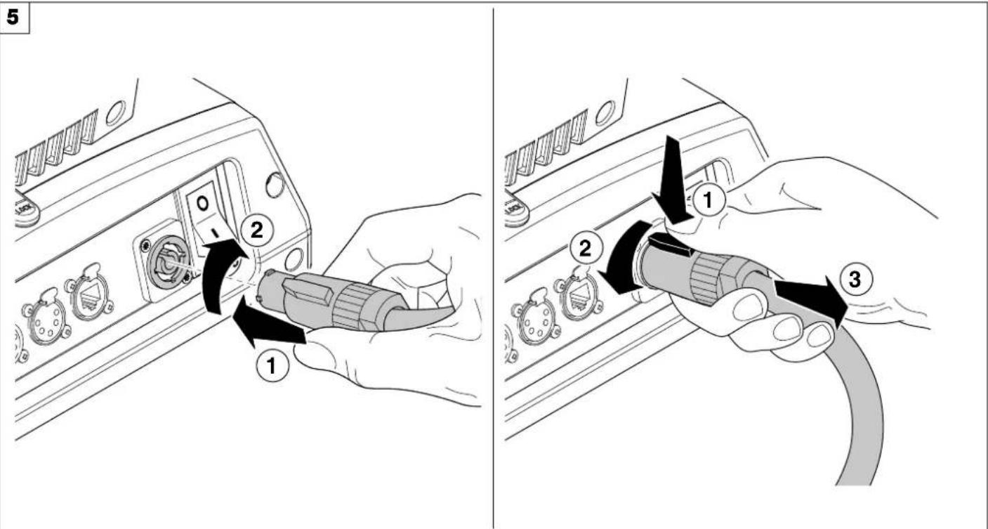
Connecting and disconnecting power cable - Fig. 5
CONTROL PANEL
6
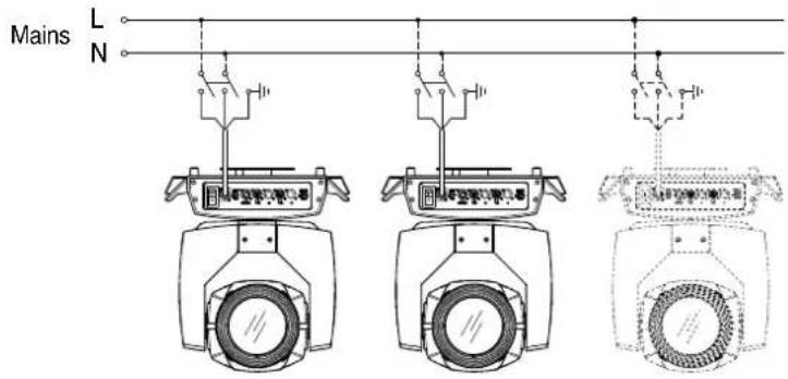
Connecting to the mains supply - Fig. 6
7
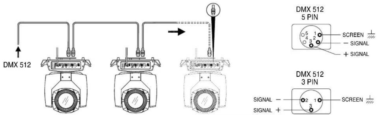
Connecting to the control signal line - Fig. 7
Use a cable conforming to specifications EIA RS-485: 2-pole twisted, shielded, 120Ohm characteristic impedance, 22-24 AWG, low capacity. Do not use microphone cable or other cable with characteristics differing from those specified. The end connections must be made using XLR type 3 or 5-pin male/female connectors. A terminating plug must be inserted into the last projector with a resistance of 120Ohm (minimum 1/4 W) between terminals 2 and 3.
IMPORTANT: The wires must not make contact with each other or with the metal casing of the connectors. The casing itself must be connected to the shield braid and to pin 1 of the connectors.
To prevent EMI disturbances, in some condition it might be necessary to clip around the Ethernet cable, as close as possible to the projector, an appropriate ferrite bead. Shielded cables must always be used.
8

Switching on the projector - Fig. 8
Press the switch. The projector starts resetting the effects. At the same time, the following information scrolls on the display:

AYPAKY
Model
SHARPY
Firmware
Version X.X.X
Date - Hour
xxx (Fixture ID)
Dmx Address xxx
System errors
E: ....
W:
On conclusion of resetting in case of absence of the dmx signal, Pan and Tilt move to the "Home" position (Pan 128 bit - Tilt 128 bit). The control panel (Fig. 8) has a display and buttons for the complete programming and management of the projector menu. The display can be in one of two conditions: rest status and setting status. When it is in the rest status, the display shows the projector's DMX address and the Fixture ID address (if set).
During menu setting status, after a wait time (about 30 seconds) without any key having been pressed, the display automatically returns to rest status. It should be noted that when this condition occurs, any possible value that has been modified but not yet confirmed with the OK key will be cancelled.
Continue →
9
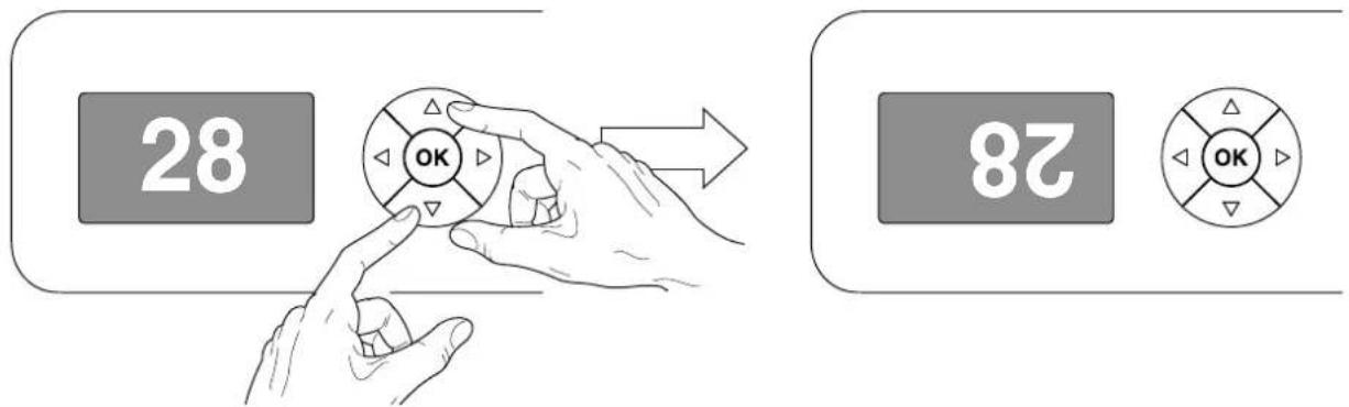
Reversal of the display - Fig. 9
To activate this function, press UP ⬆ and DOWN ⬇ keys simultaneously while the display is in the rest mode. This status will be memorised and maintained even for the next time it will be switched on. To return to the initial state, repeat the operation all over again.
Setting the projector starting address
On each projector, the starting address must be set for the control signal (addresses from 1 to 512).
The address can also be set with the projector switched off.
Setting the projector Fixture ID
On each projector, the Fixture ID address must be set for an easy identification of the fixtures in an installation (ID from 1 to 255).
The Fixture ID address can be set with the projector switched off.
Functions of the buttons - Using the menu
| OK | Confirms the displayed value, or activates the displayed function, or enters the successive menu. |
| DOWN | Decreases the value displayed (with auto-repetitions) or passes to the next item in the menu. |
| UP | Increases the value displayed (with auto-repetitions) or passes to the previous item in a menu. |
| LEFT | Return to the top level |
| RIGHT | Commute from units, tens, hundreds, in the "Address", "Fixture ID" and "Calibration" menù. |
USING THE MENU:
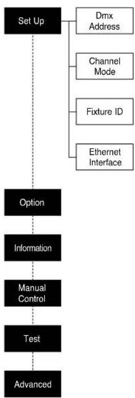
1) Press OK once – “Main Menu” appears on the display.
2) Use the UP ⬆ and DOWN ⬇ keys to select the menu to be used:
- Setup (Setup Menu): To set the setting options.
- Option (Option Menu): To set the operating options
- Informations (Informations Menu): To read the counters, software version and other information.
- Manual Control (Manual control Menu): To trigger the test and manual control functions.
- Test (Test Menu): To check the proper functioning of effects
- Advanced (Advanced Menu): Access to the "Advanced menu" is recommended for a trained technical personnel.
3) Press OK to display the first item in the selected menu.
4) Use the UP ⬆ and DOWN ⬇ keys to select the MENU items.
Setting addresses and options with the projector disconnected
The projector's DMX address, as well as other possible operating options, can also be set when the appliance is disconnected from the electricity supply. All that is needed is to press OK to momentarily activate the display and thus access the settings. Once the required operations have been carried out, the display will switch off again after a wait time of 30 seconds.
1
flowchart
graph TD
    A["Set Up"] --> B["Dmx Address"]
    A --> C["Channel Mode"]
    A --> D["Fixture ID"]
    A --> E["Ethernet Interface"]
    F["Option"] --> G["Information"]
    G --> H["Manual Control"]
    H --> I["Test"]
    I --> J["Advanced"]
2
flowchart
graph TD
    A["Option"] --> B["Lamp Dmx"]
    A --> C["Safety Black Out"]
    A --> D["Pan / Tilt"]
    D --> E["Invert Pan"]
    D --> F["Invert Tilt"]
    D --> G["Swap Pan-Tilt"]
    D --> H["Encoder Pan-Tilt"]
    D --> I["P/T Homing Mode"]
    D --> J["Pan Home Def Pos"]
    D --> K["Tilt Home Def Pos"]
    D --> L["Color"]
    L --> M["Fixed Wheel Shortcut"]
    L --> N["Linear Movement"]
    L --> O["Shutter"]
    O --> P["Shutter On Error"]
    L --> Q["Dimmer Filter Type"]
    Q --> R["Display"]
    Q --> S["Setting"]
    S --> T["Default Preset"]
    S --> U["User Preset 1"]
    S --> V["User Preset 2"]
    S --> W["User Preset 3"]
3
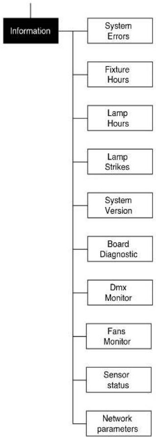
flowchart
graph TD
    A["Information"] --> B["System Errors"]
    A --> C["Fixture Hours"]
    A --> D["Lamp Hours"]
    A --> E["Lamp Strikes"]
    A --> F["System Version"]
    A --> G["Board Diagnostic"]
    A --> H["Dmx Monitor"]
    A --> I["Fans Monitor"]
    A --> J["Sensor status"]
    A --> K["Network parameters"]
4
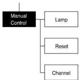
flowchart
graph TD
    A["Manual Control"] --> B["Lamp"]
    A --> C["Reset"]
    A --> D["Channel"]
5
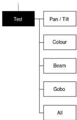
flowchart
graph TD
    A["Test"] --> B["Pan / Tilt"]
    A --> C["Colour"]
    A --> D["Beam"]
    A --> E["Gobo"]
    A --> F["All"]
6
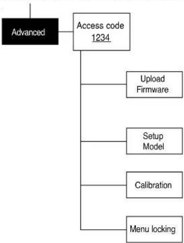
flowchart
graph TD
    A["Advanced"] --> B["Access code 1234"]
    B --> C["Upload Firmware"]
    B --> D["Setup Model"]
    B --> E["Calibration"]
    B --> F["Menu locking"]
NOTE: On grey the default options
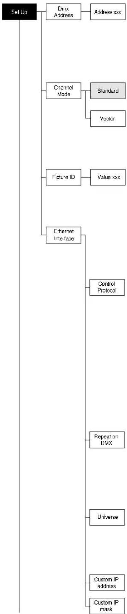
flowchart
graph TD
    A["Set Up"] --> B["Dmx Address"]
    B --> C["Address xxx"]
    A --> D["Channel Mode"]
    D --> E["Standard"]
    D --> F["Vector"]
    A --> G["Fixture ID"]
    G --> H["Value xxx"]
    A --> I["Ethernet Interface"]
    I --> J["Control Protocol"]
    I --> K["Repeat on DMX"]
    I --> L["Universe"]
    I --> M["Custom IP address"]
    I --> N["Custom IP mask"]
SET UP MENU
DMX ADDRESS
NOTE: without the DMX signal the Address (XXX) flashing
Allows you to select the DMX ADDRESS.
1) Press OK - the current DMX Adress appear on the display.
2) Use the UP ▲ and DOWN ▼, RIGHT ▶ keys to plan the DMX Address.
3) Press Ⓞ to confirm the selection or LEFT ⏻ to keep current settings.
CHANNEL MODE
Allows you to select a channel arrangement from the two available.
1) Press Ⓞk - the current settings appear on the display (Standard or Vector).
2) Use the UP ⬆ and DOWN ⬇ keys to select one of the following settings:
- Standard
- Vector
3) Press Ⓞ to confirm the selection or LEFT ⏻ to keep current settings.
FIXTURE ID
Allows you to select the FIXTURE ID.
1) Press Ⓞk - the current Fixture ID appear on the display.
2) Use the UP ⬆, DOWN ⬇, RIGHT ⬇ keys to plan the Fixture ID.
3) Press OK to confirm the selection or LEFT ◀ to keep current settings.
ETHERNET INTERFACE
It lets you set the Ethernet settings to be attributed to the projector.
1) Premere OK.
2) Use the UP ⬆ and DOWN ⬇ keys to select the "Ethernet Interface" options to set:
Control Protocol
It lets you select the "Control Protocol" Art-net to assign according to the control unit used:
1) Press Ⓞ the current setting appears on the display.
2) Use the UP ▲ and DOWN ▼ keys to select one of the following settings:
- Disabled
- Art-net on IP 2
- Art-net on IP 10
- Art-net Custom IP
3) Press OK to confirm the selection or LEFT 🔑 to keep the current setting. If the Control Protocol option is set on Disabled, when an IP address (IP2, IP10 or IP Custom) is selected, the projector immediately initializes the IP address that was just selected.
If the Control Protocol option is enabled (IP2, IP10 or IP Custom) and a new one is selected that is different from the previous one, the projector must be restarted so that it will be correctly initialized.
Repeat on DMX
It lets you enable the transmission of the Ethernet protocol by DMX signal to all the connected projectors.
1) Press ☐ the current setting appears on the display.
2) Use the UP ⬆ and DOWN ⬇ keys to select one of the following settings:
- Disabled: DMX transmission disabled.
- Enabled on primary: DMX transmission enabled.
3) Press OK to confirm the selection or LEFT ◀ to keep the current setting.
Universe
It lets you assign the "Universe" number to be assigned to a series of projectors.
1) Press OK – the current Universe address appears on the display.
2) Use the UP ⬇, DOWN ⬇, RIGHT ⬇ keys to set the Universe address.
3) Press Ⓞ to confirm the selection or LEFT ⏻ to keep the current setting.
Custom IP address
Allows you to set the IP address manually by the user default.
Custom IP mask
Allows you to set manually the Subnet Mask by the user default.
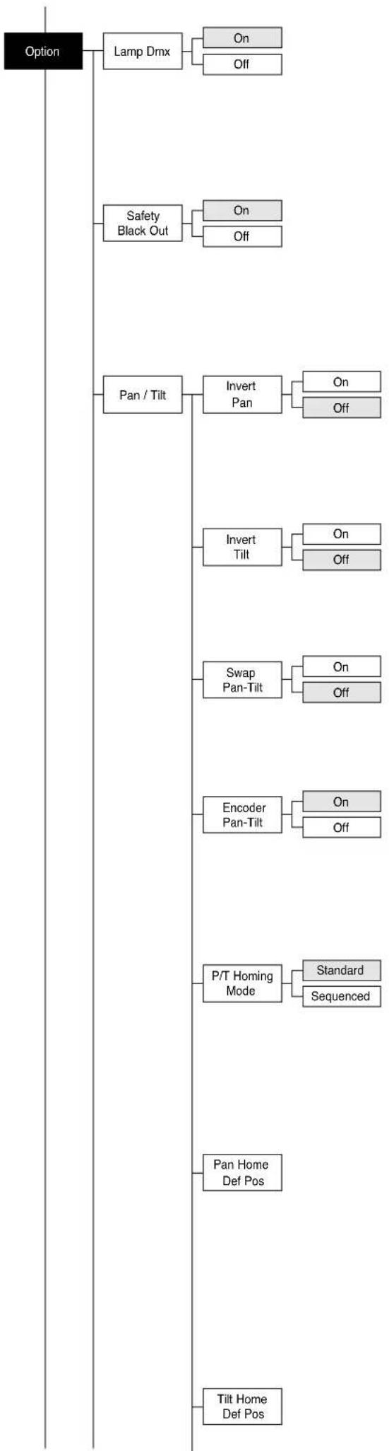
flowchart
graph TD
    A["Option"] --> B["Lamp Dmx"]
    B --> C["On"]
    B --> D["Off"]
    E["Safety Black Out"] --> F["On"]
    E --> G["Off"]
    H["Pan / Tilt"] --> I["Invert Pan"]
    I --> J["On"]
    I --> K["Off"]
    L["Invert Tilt"] --> M["On"]
    L --> N["Off"]
    O["Swap Pan-Tilt"] --> P["On"]
    O --> Q["Off"]
    R["Encoder Pan-Tilt"] --> S["On"]
    R --> T["Off"]
    U["P/T Homing Mode"] --> V["Standard"]
    U --> W["Sequenced"]
    X["Pan Home Def Pos"] --> Y["Tilt Home Def Pos"]
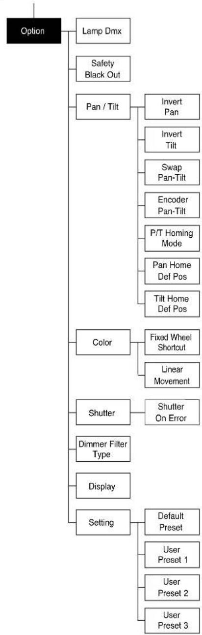
OPTIONS MENU
LAMP DMX
Used for enabling lamp remote control channel.
1) Press OK - the current settings appear on the display (On or Off).
2) Use the UP ⬆ and DOWN ⬇ keys to enable (On) or disable (Off) the lamp remote control channel.
3) Press OK to confirm the selection or LEFT ⏻ to keep current settings.
SAFETY BLACK OUT
This allows the Dimmer's automatic lock option to be activated after 3 seconds with no incoming DMX signal.
1) Press OK - the current setting (On or Off) appears on the display.
2) Use the UP ⬆, DOWN ⬇ keys to enable (ON) or disable (Off) the Dimmer's lock option after 3 seconds with no incoming DMX signal.
3) Press Ⓞ to confirm the selection or LEFT ⏻ to keep the current setting.
PAN / TILT
Invert pan
Used for reversing Pan movement.
1) Press OK - the current settings appear on the display (On or Off).
2) Use the UP ⬆ and DOWN ⬇ keys to enable (On) or disable (Off) PAN inversion.
3) Press OK to confirm the selection or LEFT ⏻ to keep current settings.
Invert tilt
Used for reversing tilt movement.
1) Press Ⓞ - the current settings appear on the display (On or Off).
2) Use the UP ⬆ and DOWN ⬇ keys to enable (On) or disable (Off) Tilt inversion.
3) Press Ⓞ to confirm the selection or LEFT ⏻ to keep current settings.
Swap Pan-Tilt
Used for swapping Pan and Tilt channels (as well as Pan fine and Tilt fine).
1) Press OK - the current settings appear on the display (On or Off).
2) Use the UP ⬆ and DOWN ⬇ keys to enable (On) or disable (Off)
Pan and Tilt channel swap.
3) Press Ⓞ to confirm the selection or LEFT ⬇ to keep current settings.
Encoder Pan-Tilt
Used for enabling the Pan / Tilt encoders.
1) Press Ⓞk - the current settings appear on the display (On or Off).
2) Use the UP ⬆ and DOWN ⬇ keys to enable (On) or disable (Off) Pan / Tilt encoders.
3) Press Ⓞ to confirm the selection or LEFT ⏻ to keep current settings.
You can quickly disable the Pan and Tilt Encoder by simultaneously pressing the UP ⬆ and DOWN ⬇ keys in the "Main Menu".
P/T Homing Mode
Lets you set the initial projector Reset mode.
1) Press OK, the current setting appears on the display.
2) Use the UP ⬆ and DOWN ⬇ keys to select one of the following settings:
Standard: Pan & Tilt are simultaneously reset.
Sequenced: Tilt is reset first followed by Pan.
3) Press Ⓜ to confirm the selection or LEFT ⏻ to keep the current setting.
Pan Home Def Pos
Lets you assign the Pan channel "home" position at the end of Reset, without a DMX input signal.
1) Press Ⓞ, the current setting appears on the display.
2) Use the UP ⬆ and DOWN ⬇ keys to select one of the following settings:
0 degree
90 degrees
180 degrees
270 degrees (default)
3) Press Ⓞ to confirm the selection or LEFT ⏻ to keep the current setting.
Tilt Home Def Pos
Lets you assign the Tilt channel "home" position at the end of Reset, without a DMX input signal.
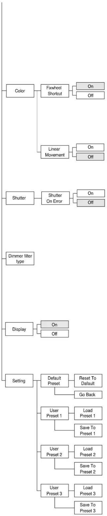
flowchart
graph TD
    A["Color"] --> B["Fixwheel Shortcut"]
    B --> C["On"]
    B --> D["Off"]
    B --> E["Linear Movement"]
    E --> F["On"]
    E --> G["Off"]
    H["Shutter"] --> I["Shutter On Error"]
    I --> J["On"]
    I --> K["Off"]
    L["Dimmer filter type"] --> M["Display"]
    M --> N["On"]
    M --> O["Off"]
    P["Setting"] --> Q["Default Preset"]
    Q --> R["Reset To Default"]
    Q --> S["Go Back"]
    Q --> T["User Preset 1"]
    T --> U["Load Preset 1"]
    T --> V["Save To Preset 1"]
    P --> W["User Preset 2"]
    W --> X["Load Preset 2"]
    W --> Y["Save To Preset 2"]
    P --> Z["User Preset 3"]
    Z --> AA["Load Preset 3"]
    Z --> AB["Save To Preset 3"]
1) Press OK, the current setting appears on the display.
2) Use the UP ⬆ and DOWN ⬇ keys to select one of the following settings: 0%
12.5%
25%
50% (default)
75%
87.5%
100%
3) Press Ⓞ to confirm the selection or LEFT ⬇ to keep the current setting.
COLOR
Fixed wheel short-cut
Used for optimizing color change time so that the disc turns in the direction that requires shorter movement.
1) Press Ⓞ – the current settings appear on the display (On or Off).
2) Use the UP ⬆ and DOWN ⬇ keys to enable (On) or disable (Off) color change optimization.
3) Press OK to confirm the selection, or LEFT ◀ to keep current settings.
Linear Movement
It enables the linear movement of the colour wheel.
1) Press Ⓞ – the current settings appear on the display (On or Off).
2) Use the UP ⬇ and DOWN ⬇ keys to enable (On) or disable (Off) the linear movement of the colour wheel.
3) Press Ⓞ to confirm the selection, or LEFT ⬇ to keep current settings.
SHUTTER
Shutter on error
Used for automatically closing the stop/strobe in the event of Pan/Tilt position error.
1) Press OK - the current settings appear on the display (On or Off).
2) Use the UP ⬆ and DOWN ⬇ keys to enable (On) or disable (Off) automatic stop/strobe closing in the event of Pan/Tilt position error.
3) Press Ⓞ to confirm the selection, or LEFT ⏻ to keep current settings.
DIMMER FILTER TYPE
It lets you best optimize the "Dimmer curve" according to that set on the control unit. One of the following 2 options can be selected:
- DMX follower
Dimmer movement speed/linearity follows the DMX values set by the control desk.
- Position dependent
Dimmer movement speed follows the DMX values set by the control unit taking into account the physical Dimmer starting position.
DISPLAY
Used for automatically reduce brightness on the display after about 30 seconds in idle.
1) Press OK - the current settings appear on the display (On or Off).
2) Use the UP ⬆ and DOWN ⬇ keys to enable (On) or disable (Off) the decreasing of display brightness.
3) Press Ⓞ to confirm the selection or LEFT ⏻ to keep current settings.
SETTING
Used to save 3 different settings of the items in the options menu and relative submenus.
1) Press OK - "Default preset" appears on the display.
2) Use the UP ⬆ and DOWN ⬇ keys to select one of the following configurations:
- Default preset (*)
- User preset 1
- User preset 2
- User Preset 3
3) Press Ⓞ - "Load preset X" appears on the display.
4) Use the UP ▲ and DOWN ▼ keys to select:
- Load preset X to recall a previously stored configuration.
- Save to preset X to store the current configuration.
a confirmation message (Are you sure?) appears on the display.
5) Select YES to confirm the selection or NO to keep the current setting and return to the next higher level.
(*) DEFAULT PRESET
By pressing the RIGHT▶ key and the LEFT ⏻ key simultaneously once entered in the "main menu" it is possible to quickly (short cut) reset the default settings (DEFAULT PRESET).
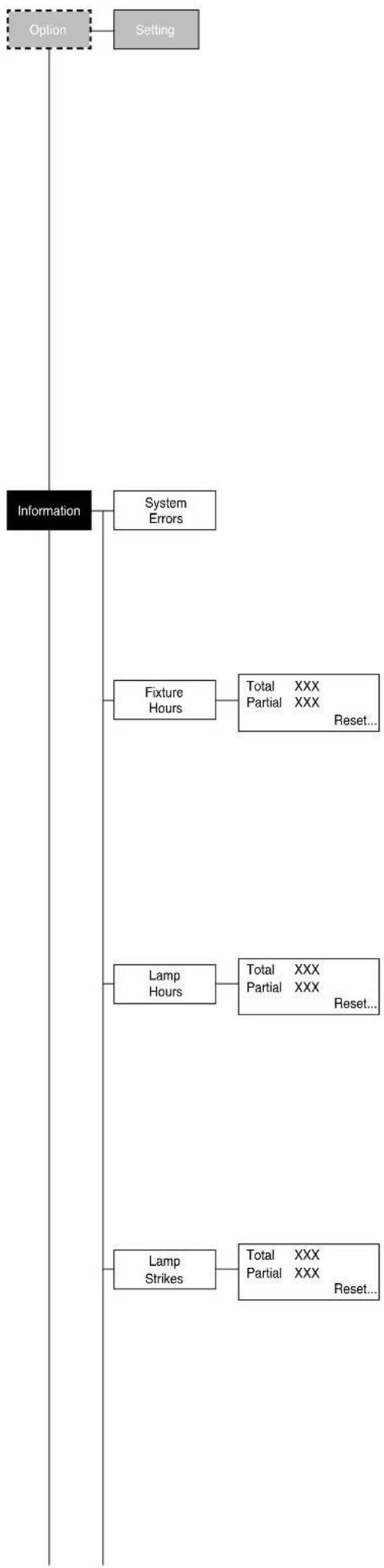
flowchart
graph TD
    A["Option"] --> B["Setting"]
    C["Information"] --> D["System Errors"]
    C --> E["Fixture Hours"]
    E --> F["Total XXX Partial XXX Reset..."]
    C --> G["Lamp Hours"]
    G --> H["Total XXX Partial XXX Reset..."]
    C --> I["Lamp Strikes"]
    I --> J["Total XXX Partial XXX Reset..."]
Used for restoring default values on all options menu items and relevant submenus.
1) Press (OK), a confirmation message (Are you sure?) appears on the display.
2) Select YES to confirm the selection or NO to keep current setting.
OPTION DEFAULT
Lamp DMX On
Safety Black Out Off
Invert Pan Off
Invert Tilt Off
Swap Pan-Tilt Off
Encoder Pan-Tilt On
P/T Homing Mode Standard
Pan Home Def Pos 270 degrees
Tilt Home Def Pos 50%
Fixed Wheel Shortcut On
Linear Movement Off
Shutter on error Off
Dimmer Filter Type DMX follower
Display On
INFORMATION MENU
SYSTEM ERRORS
Shows a list of warnings and messages relevant to errors occurred since the fixtures switching-on.
1) Pressing Ⓞ you are allowed to reset the SYSTEM ERRORS list.
A confirmation message (Are you sure you want to clear error list ?) appears on the display.
2) Select YES to reset the list or NO to go back.
FIXTURE HOURS
Used for displaying projector operating hours (total and partial).
1) Press Ⓞk - Hours total and partial appears on the display.
Total counter
Counts the number of projector working life hours (from manufacture to date).
Partial counter
Counts the number of partial projector working life hours since the last reset to date.
2) Press Ⓞ to reset partial projector working hours a confirmation message (Are you sure?) appears on the display.
3) Select YES to reset partial projectors counter or NO to keep the current setting and return to the top menu level.
LAMP HOURS
Used for displaying the lamp working hours (total and partial).
1) Press OK - Hours total and partial appears on the display.
Total counter
Counts the number of projector working hours with the lamp on (from manufacture to date).
Partial counter
Counts the number of lamp working hours since the last reset to date.
2) Press Ⓞ to reset partial lamp working hours, a confirmation message (Are you sure?) appears on the display.
3) Select YES to reset partial counter or NO to keep the current setting and return to the top menu level
LAMP STRIKES
Used for displaying the number of times the lamp was turned on (total and partial).
1) Press Ⓜ - the number of times the lamp was turned on (total and partial) appears on the display.
Total counter
Counts the number of times the lamp was turned on (from manufacture to date).
Partial counter
Counts the number of times the lamp was turned on since the last reset to date.
2) Press Ⓜ to reset partial lamp strikes hours, a confirmation message (Are you sure?) appears on the display.
3) Select YES to reset partial counter or NO to keep the current setting and return to the top menu level
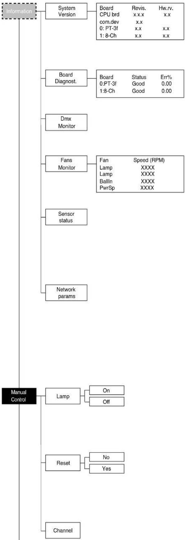
flowchart
graph TD
    A["Information"] --> B["System Version"]
    B --> C["Board CPU brd com.dev 0: PT-3f 1: 8-Ch"]
    C --> D["Board Diagnost."]
    D --> E["Board Status Good 0:PT-3f 1:8-Ch"]
    E --> F["Dmx Monitor"]
    F --> G["Fans Monitor"]
    G --> H["Fan Lamp BallIn PwrSp"]
    H --> I["Sensor status"]
    I --> J["Network params"]
    J --> K["Manual Control"]
    K --> L["Lamp"]
    L --> M["On Off"]
    K --> N["Reset"]
    N --> O["No Yes"]
    K --> P["Channel"]
SYSTEM VERSION
Used for displaying the software and hardware version of each board installed in the projector.
CPU brd (CPU board)
0: PT-3f (Pan / Tilt board)
1: 8-Ch (8 channel board)
BOARD DIAGNOSTIC
Used for displaying the status error of each board installed in the projector:
0: PT-3f (Pan / Tilt board)
1: 8-Ch (8 channel board)
DMX MONITOR
Used for displaying the projector DMX channel level in bit (Val) and in percentage (Perc).
FANS MONITOR
Used for displaying the speed of each fan installed in the projector:
Lamp (Lamp Fan)
Ball. IN (Ballast IN Fan)
PwrSp (Power Supply Fan)
SENSOR STATUS
It lets you check the correct operations of each "sensor" installed in the projector, each channel is associated with one of the following three parameters:
• n.a.= sensor not available
• ON= sensor working
• OFF= sensor defective
NETWORK PARAMS
Allows the "Network" parameters of the projector to be displayed or:
IP address: Internet Protocol address (two projectors must not have the same IP address)
IP mask: 255.0.0.0
Mac address: Media Access Control: the projector's Ethernet Address
MANUAL CONTROL
LAMP
Used for turning lamp on and off from the projector control panel.
1) Press OK - the current settings appear on the display (On or Off).
2) Use the UP ▲ and DOWN ▼ keys to turn the lamp on (On) or off (Off)
3) Press OK to confirm the selection or LEFT ⬆ to keep current settings and return to the top level.
RESET
Used for resetting the projector.
1) Press OK to reset the projectors, a confirmation message (Are you sure?) appears on the display.
2) Select YES to starting reset the fixture or NO to keep the current setting and return to the top menu level.
CHANNEL
Used for setting channel levels from the projector control panel.
1) Press OK - the first channel appears on the display.
2) Use the UP ▲ and DOWN ▼ keys to select the required channel:
3) Press Ⓞ and use the UP ⬆ and DOWN ⬇ keys to select the required DMX level (value between 0 and 255).
4) Press LEFT ⏻ to return to the top menu level.
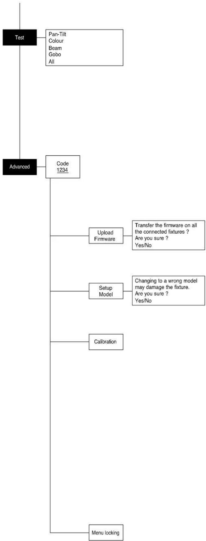
flowchart
graph TD
    A["Test"] --> B["Pan-Tilt<br>Colour<br>Beam<br>Gobo<br>All"]
    A --> C["Code 1234"]
    C --> D["Upload Firmware"]
    D --> E["Transfer the firmware on all the connected fixtures ?<br>Are you sure ?<br>Yes/No"]
    C --> F["Setup Model"]
    F --> G["Changing to a wrong model may damage the fixture.<br>Are you sure ?<br>Yes/No"]
    C --> H["Calibration"]
    H --> I["Menu locking"]
TEST MENU
TEST
Allows you to check the proper functioning of effects.
1) Press OK to return to the top menu level.
2) Use the UP ▲ and DOWN ▼ keys to select the required test.
3) Press OK to confirm the selection or LEFT ⬆ to keep current settings.
Test sequence:
Pan - Tilt effects (Pan & Tilt)
Colour effects (Colour wheel)
Beam effects (Stopper-Strobe / Dimmer / Prism / Frost)
Gobo effects (Static gobo)
All effects
ADVANCED MENU
To enable the "Advanced Menu" set up the "Access code" (1234) using the UP ⬇, DOWN ⬇, RIGHT ⬇ keys.
Press Ⓞk - "Menu advanced" appears on the display
UP LOAD FIRMWARE
Allows you to transfer the firmware from 1 fixture to all the connected fixtures.
1) Press OK, a confirmation message appears on the display.
2) Select YES to start the firmware loading or NO to keep the current setting and return to the top menu level
SETUP MODEL
Allows you to change the default model of projector.
1) Press OK a confirmation message appears on the display.
2) Select YES to define the model of projector or NO to keep the current setting and return to the top menu level.
CALIBRATION
Allows you to adjust effects from the control panel to obtain perfect uniformity between the projectors.
1) Press OK - "channels" appears on the display.
2) Using the UP ⬆ and DOWN ⬇ keys, select the effect you wish to regulate.
3) Press ⏻ and use the RIGHT ⬇, UP ⚠ and DOWN ⭕ buttons to make the adjustment by setting a value between 0 and 255.
4) Press Ⓞ to confirm the selection or LEFT ⏻ to keep current settings and return to the top level.
FACTORY DEFAULT
Allows you to restore default values of all channels (128).
1) Press Ⓞ – a confirmation message appears on the display (Reset calibration to factory default ?).
2) Select YES to reset calibration to factory default or NO to keep the current setting and return to the top menu level.
MENU LOCKING
It allows you to assign a password to lock the access to the user menu, so that only users know the password can change settings. The password is 4-digit number.
1011
natural_image
Technical line drawing of a mechanical optical or radar device with labeled components (no readable text or symbols)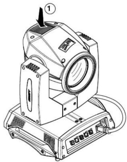
natural_image
Technical line drawing of a mechanical optical device with labeled component (no text or symbols beyond basic diagram)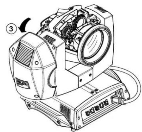
natural_image
Technical line drawing of a mechanical device with labeled parts (no readable text or symbols)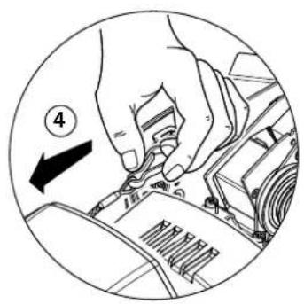
natural_image
Illustration of a hand turning a car engine component with a numbered arrow indicating direction (no text or symbols present)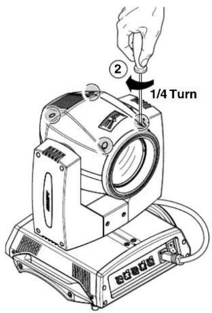
Locking and releasing Pan and Tilt movements - Refer to the instructions in the UNPACKING AND PREPARATION section.
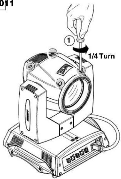
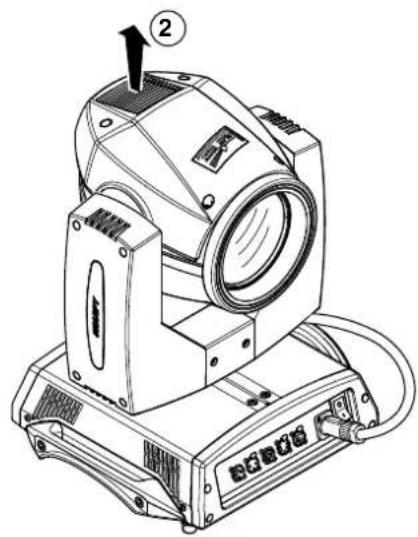
Opening the head covers - Fig. 10.
Closing the head covers - Fig. 11.
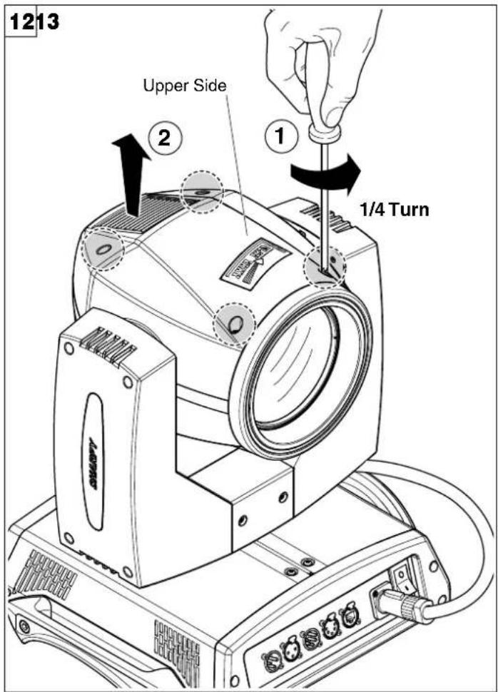
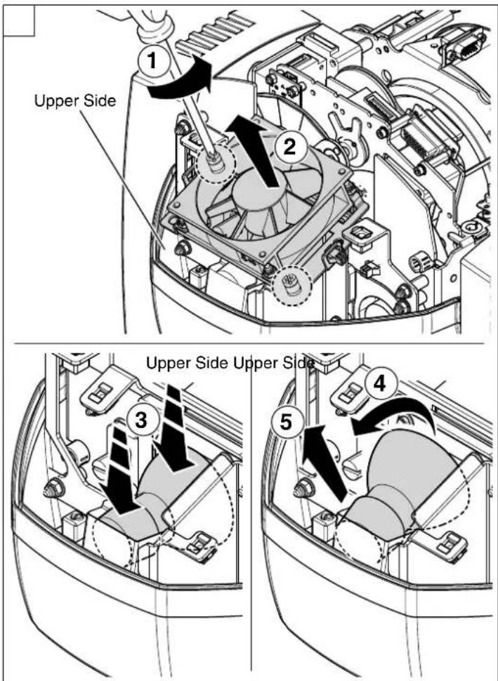
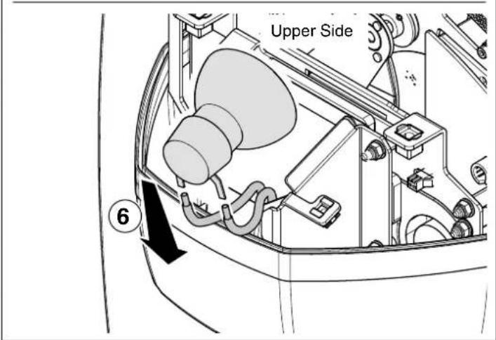
Opening and closing lamp compartment - Fig. 12
Lamp change - Fig 13
Take the new lamp out of its package and insert in the fitting.
WARNING: do not touch the lamp's envelope with bare hands. Should this happen, clean the bulb with a cloth soaked in alcohol and dry it with a clean, dry cloth.
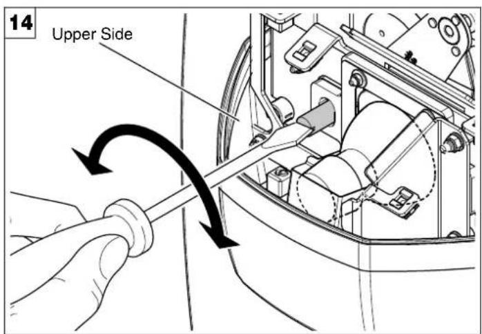
Lamp regulation - Fig. 14
To centre the lamp, turn the adjusting screw as shown in the figure.
WARNING: The lamp must be adjusted with the projector switched off. After adjusting, close the effects covers, switch on the projector and check that the adjustment has been correctly made. If necessary, switch off the projector, remove the effects covers and repeat lamp adjustment.
NOTE: To adjust the lamp vertically (with regard to the Y axis) after having replaced it, it may be necessary to operate the Calibration in the Menu Advanced on the Fixed Gobo Wheel channel.
CAUTION:
Fast lamp ON-OFF cycles (for example 10 minutes ON / 10 minutes OFF) will reduce the lamp life.
15
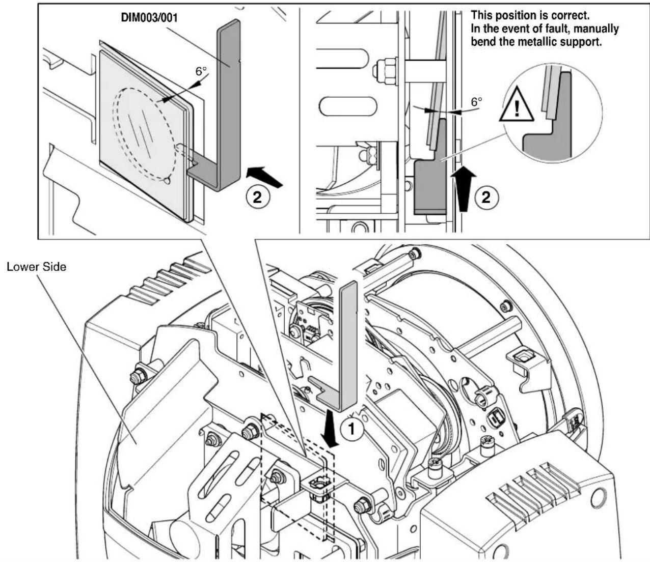
Anti IR/UV filter support template - Fig. 15
WARNING:
During maintenance and lamp replacement, we recommend you pay close attention to correct anti IR/UV filter support tilt. Incorrect tilt compromises lamp performance.
16
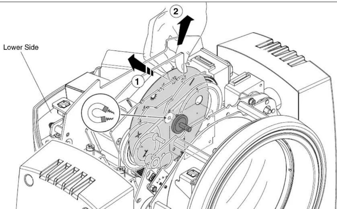
Replacing fixed gobos wheel - Fig. 16
WARNING: Before using personalised gobos wheel contact Claypaky.
17
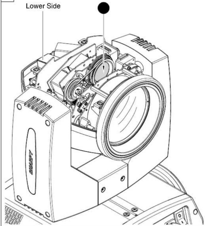
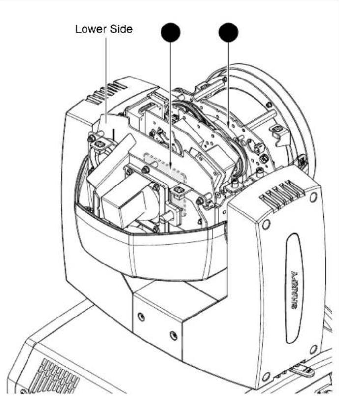
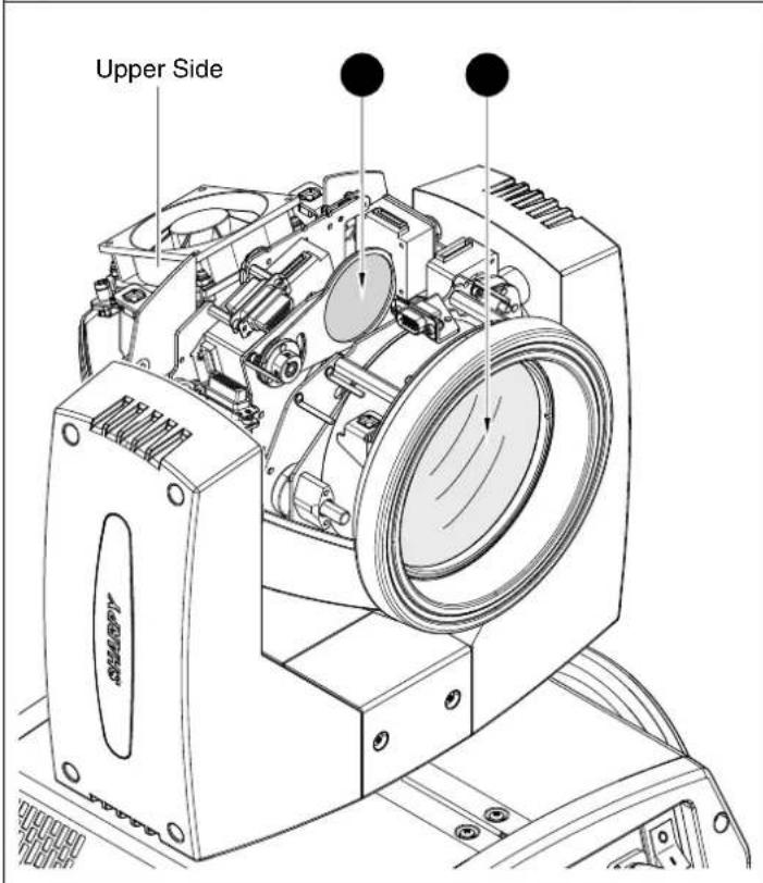
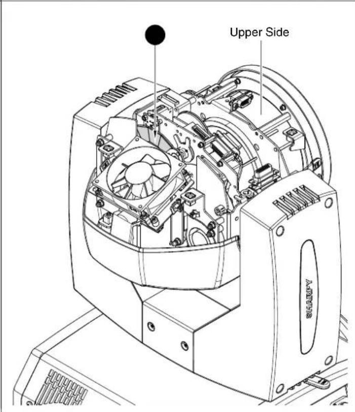
Periodical cleaning - Fig. 17
To ensure optimal operation and performance for a long time it is essential to periodically clean the parts subject to dust and grease deposits. The frequency with which the following operations are to be carried out depends on various factors, such as the amount of the effects and the quality of the working environment (air humidity, presence of dust, salinity, etc.).
Use a soft cloth dampened with any detergent liquid for cleaning glass to remove the dirt from the reflectors and filters. It is recommended that the projector undergoes an annual service by a qualified technician for special maintenance involving at least the following operations:
- General cleaning of internal parts.
- Restoring lubrication of all parts subject to friction, using lubricants specifically supplied by Claypaky.
- General visual check of the internal components, cabling, mechanical parts, etc.
- Electrical, photometric and functional checks; eventual repairs.
18
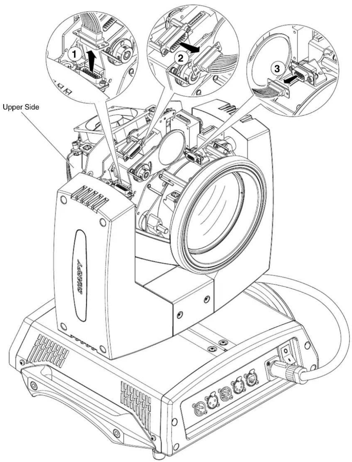
Extraction of the effect modules: Preliminary operations - Fig. 18
19
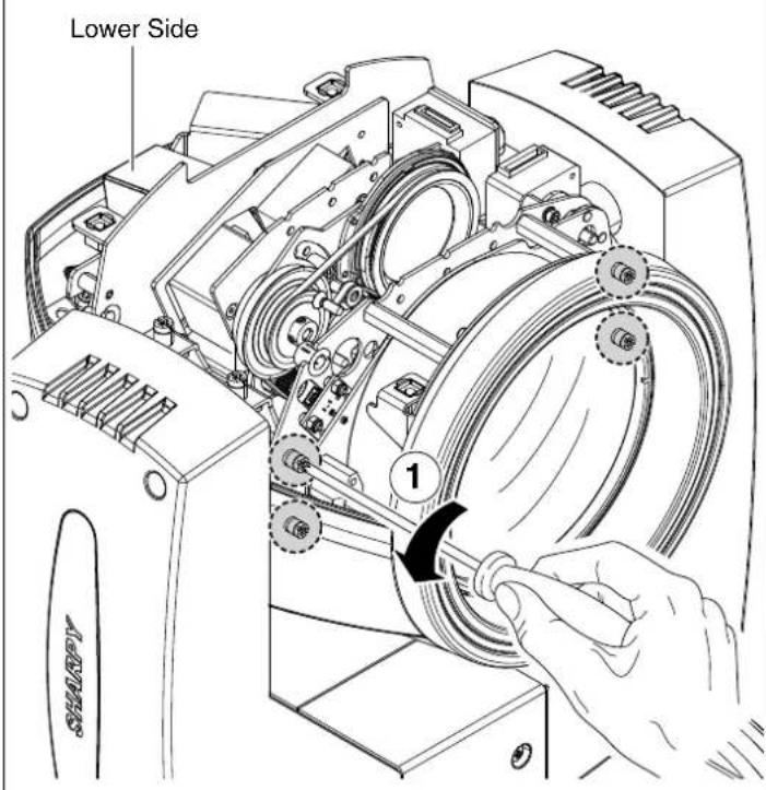
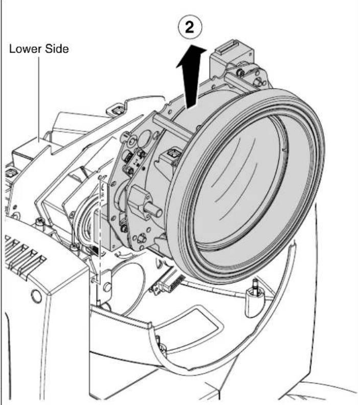
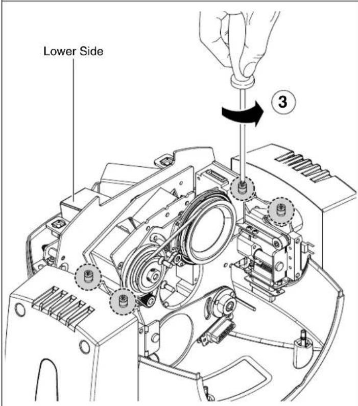
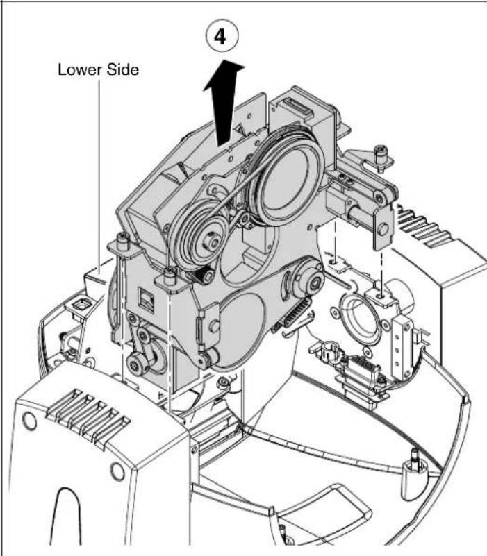
Extraction of the effect modules - Fig. 19
IMPORTANT: Grasp the modules using the support structure and not the details which could get damaged.
Insertion of the effect modules: Repeat the operations indicated in Fig. 17 and 18 in reverse order.
20
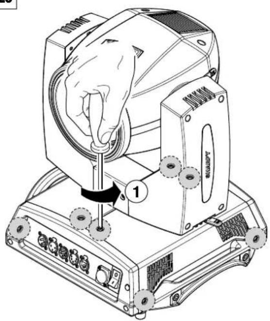
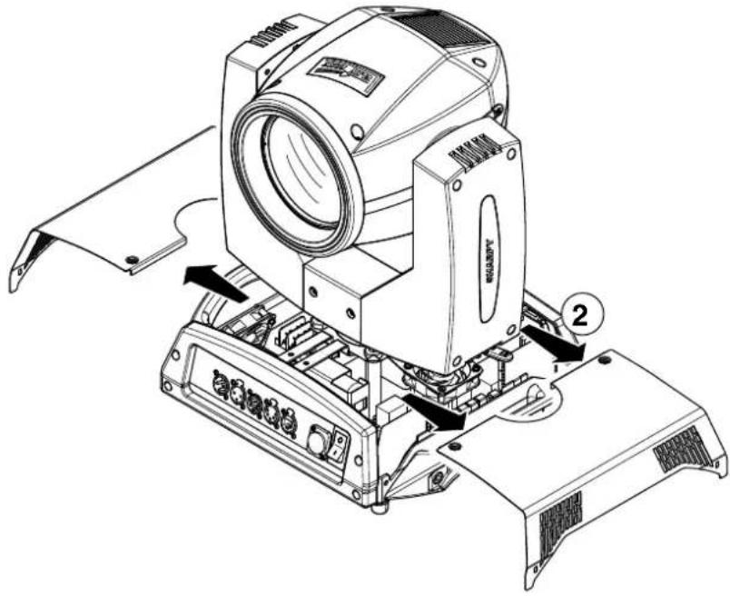
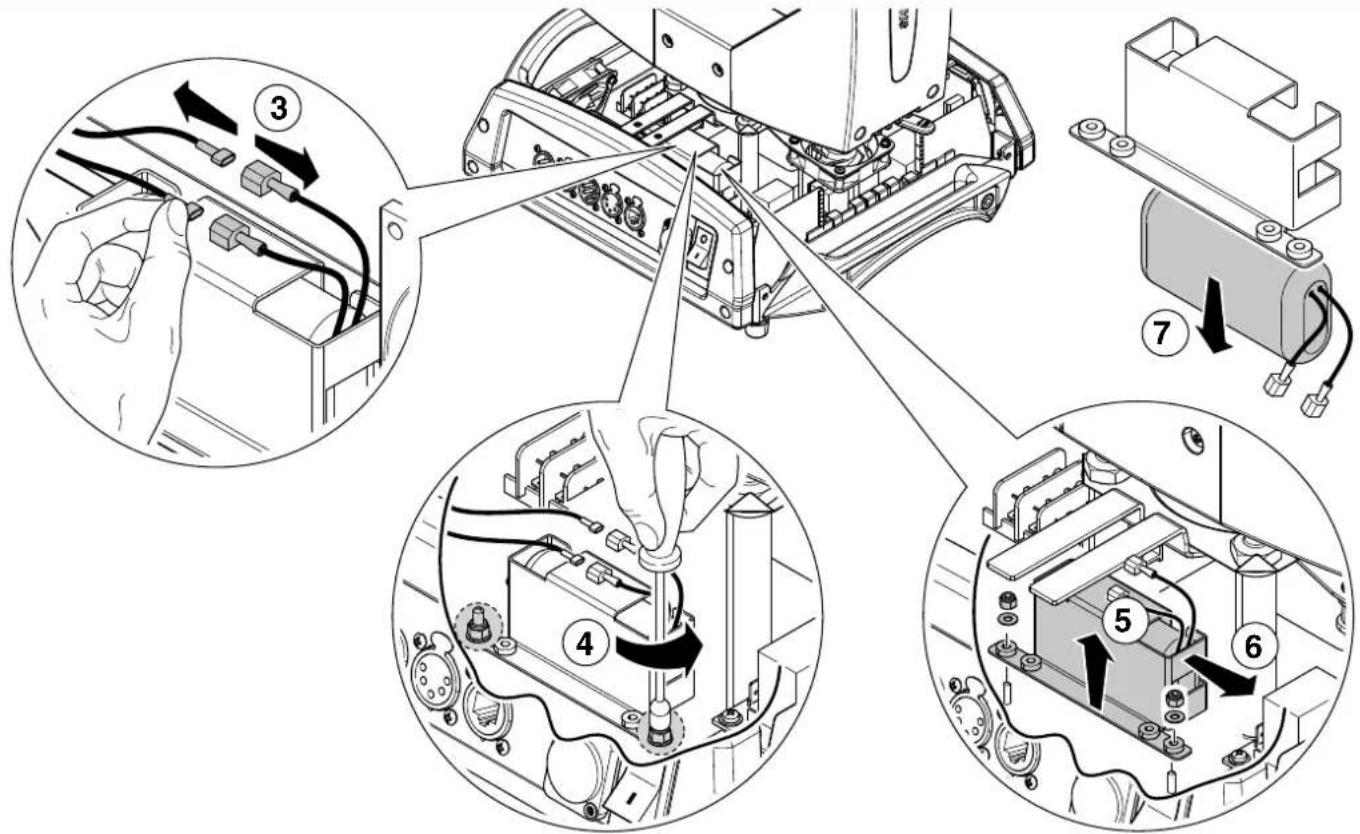
Battery removal - Fig. 20

LiFePO4
This product contains a rechargeable lithium iron tetraphosphate battery. To preserve the environment, please dispose the battery at the end of its life according to the regulation in force.
OPTIONAL ACCESSORIES
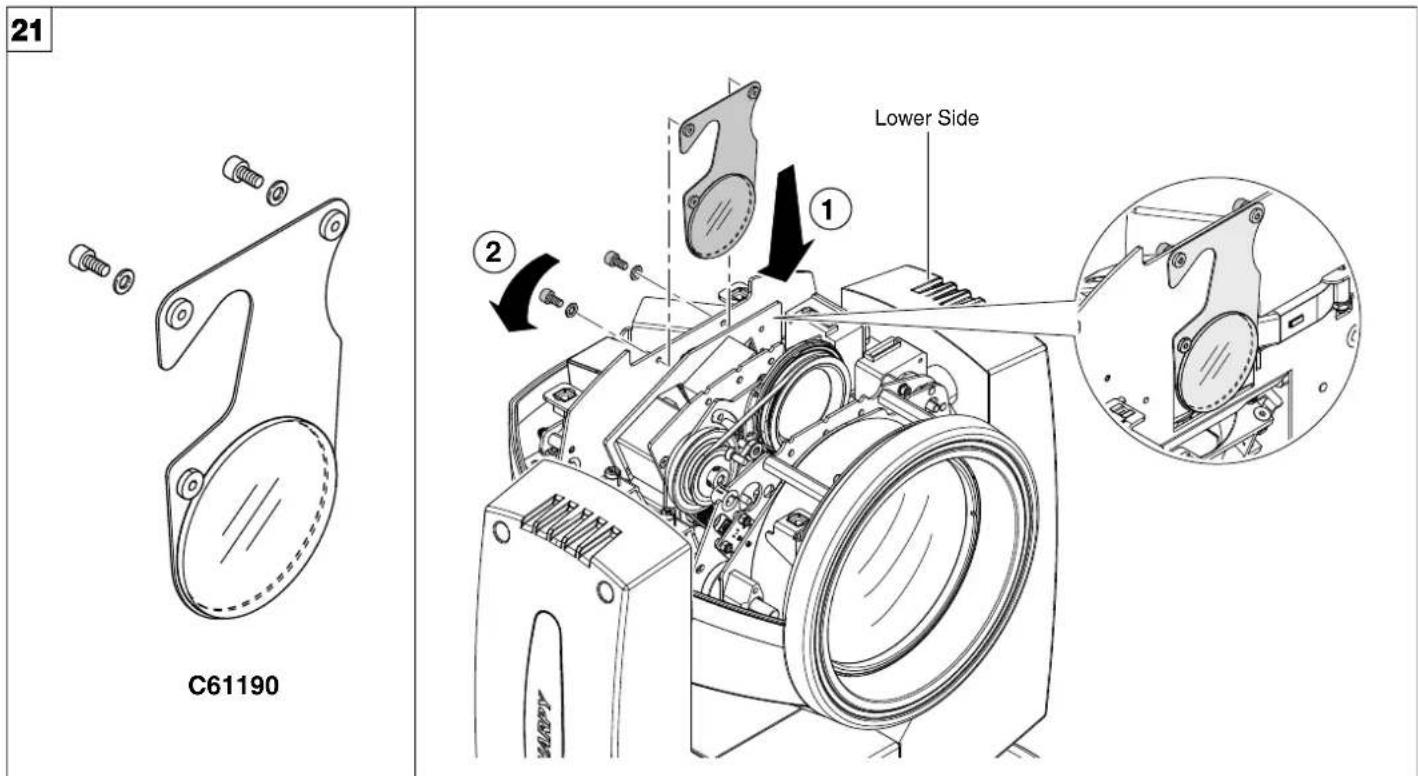
Heat screen filter - Fig. 21
An optional filter kit is also available when the SHARPY projector is used in environments that do not meet the minimum allowed distance of 12 metres from illuminated objects; when this kit is assembled, the projector can be used at a minimum distance of 8 metres from illuminated objects.
22
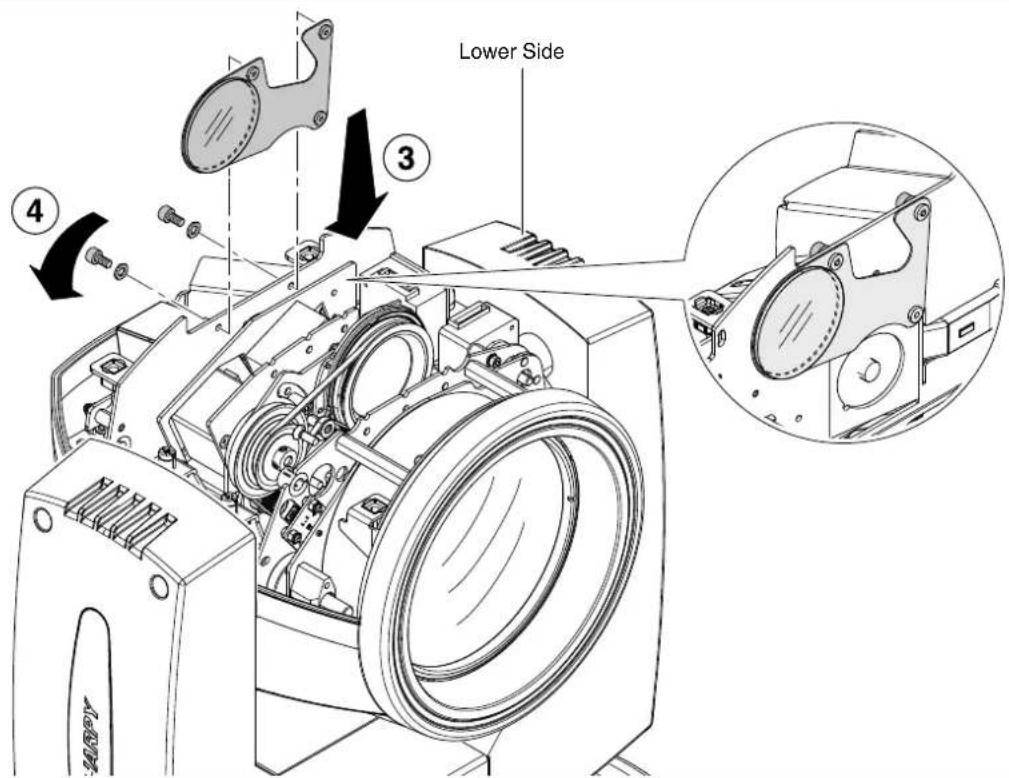
C61190 accessory can be placed inside the projector when not in use - Fig. 22
DIMENSIONS
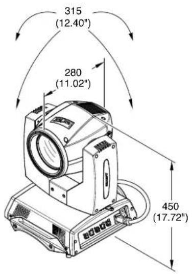
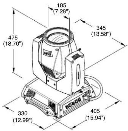
CAUSE AND SOLUTION OF PROBLEMS
| THE PROJECTOR WILL NOT SWITCH ON | PROBLEMS | ||||
| ELECTRONICS NON-OPERATIONAL | |||||
| DEFECTIVE PROJECTION | |||||
| REDUCED LUMINOSITY | |||||
| POSSIBLE CAUSES CHECKS AND REMEDIES | |||||
| ● | No mains supply. | Check the power supply voltage. | |||
| ● | Lamp exhausted or defective. | Replace the lamp. (See instructions). | |||
| ● | Signal transmission cable faulty or disconnected. | Replace the cables. | |||
| ● | Incorrect addressing. | Check addresses (see instructions). | |||
| ● | Fault in the electronic circuits. | Call an authorised technician. | |||
| ● | Lenses or reflector broken | Call an authorised technician. | |||
| ● | Dust or grease deposited. | Clean (see instructions). | |||
SHARPY
NB: To prevent accidental breakage of the effects, which could collide with each other during transport, before switching the projector OFF check that all the projector Channels have been excluded (DMX level = 0 bit).
| CHANNEL | CHANNEL MODE | |
| STANDARD VECTOR | ||
| 1 | COLOUR WHEEL | COLOUR WHEEL |
| 2 | STOP / STROBE | STOP / STROBE |
| 3 | DIMMER | DIMMER |
| 4 | STATIC GOBO CHANGE | STATIC GOBO CHANGE |
| 5 | PRISM INSERTION | PRISM INSERTION |
| 6 | PRISM ROTATION | PRISM ROTATION |
| 7 | EFFECTS MOVEMENT | EFFECTS MOVEMENT |
| 8 | FROST | FROST |
| 9 | FOCUS | FOCUS |
| 10 | PAN | PAN |
| 11 | PAN FINE | PAN FINE |
| 12 | TILT | TILT |
| 13 | TILT FINE | TILT FINE |
| 14 | FUNCTION | FUNCTION |
| 15 | RESET | RESET |
| 16 | LAMP CONTROL (with Option "Lamp Dmx" ON) | LAMP CONTROL (with Option "Lamp Dmx" ON) |
| 17 | PAN - TILT TIME | |
| 18 | COLOUR TIME | |
| 19 | BEAM TIME | |
| 20 | GOBO TIME | |
NOTE: On conclusion of resetting in case of absence of DMX signal, Pan & Tilt move to the "Home" position (Pan 128 bit - Tilt 128 bit) all the others channels stay at 0 bit.
• COLOUR WHEEL - channel 1

flowchart
graph TD
    A["Start"] --> B["Step 1"]
    B --> C["Step 2"]
    C --> D["Step 3"]
BITEFFECT
| 255 | FAST ROTATION (160 rpm) |
| 126 | SLOW ROTATION (0.2 rpm) |
| 124 | BLUE + WHITE |
| 120 | BLUE |
| 116 | CTB 8000 + BLUE |
| 111 | CTB 8000 |
| 107 | CTO 190 + CTB 8000 |
| 103 | CTO 190 |
| 99 | CTO 250 + CTO 193 |
| 94 | CTO 250 |
| 90 | CYAN - CTO 250 |
| 85 | CYAN |
| 82 | WAGENTA + CYAN |
| 77 | WAGENTA |
| 73 | YELLOW - MAGENTA |
| 69 | YELLOW |
| 64 | PINK - YELLOW |
| 60 | PINK |
| 56 | LAVENDER + PINK |
| 52 | LAVENDER |
| 47 | LIGHT GREEN + LAVENDER |
| 43 | LIGHT GREEN |
| 39 | GREEN + LIGHT GREEN |
| 35 | GREEN |
| 30 | AQUAMARINE + OEPEN |
| 26 | AQUAMARINE |
| 22 | ORANGE + AQUAMARINE |
| 18 | ORANGE |
| 13 | RED + ORANGE |
| 9 | RED |
| 5 | WHITE + RED |
| 0 | WHITE |
- STOP / STROBE - channel 2

BITEFFECT
| 252 - 255 | OPEN |
| 239 - 251 | RANDOM FAST STROSE |
| 226 - 238 | RANDOM MEDIUM STROSE |
| 213 - 225 | RANDOM SLOW STROSE |
| 208 - 212 | OPEN |
| 207 | FAST PULSATION (360 rpm) |
| 108 | SLOW PULSATION (30 rpm) |
| 104 - 107 | OPEN |
| 103 | FAST STROBE (12 flash/sec) |
| 4 | SLOW STROBE (1 flash/sec) |
| 0 - 0 | CLOSED |
• DIMMER - channel 3

BITEFFECT
| 255 | 0%-100%: 0.02 sec |
| 0 |
- STATIC GOBO CHANGE - channel 4
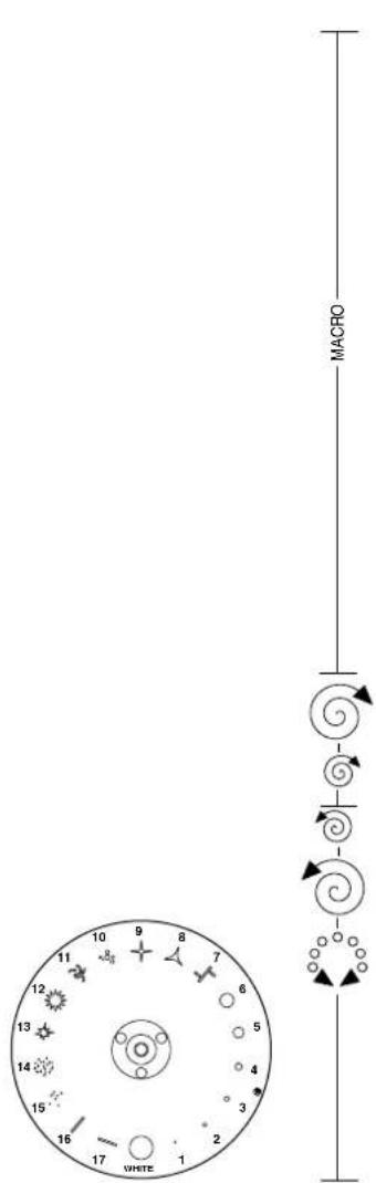
| BITEFFECT | |
| 255 | G080 16 SHAKE FAST SPEED (80 rpm) |
| 250 | G080 16 SHAKE, SLOW SPEED (24 rpm) |
| 249 | G080 15 SHAKE FAST SPEED |
| 244 | G080 15 SHAKE, SLOW SPEED |
| 243 | G080 14 SHAKE FAST SPEED |
| 237 | G080 14 SHAKE, SLOW SPEED |
| 236 | G080 13 SHAKE FAST SPEED |
| 251 | G080 13 SHAKE, SLOW SPEED |
| 250 | G080 12 SHAKE FAST SPEED |
| 224 | G080 12 SHAKE, SLOW SPEED |
| 223 | G080 11 SHAKE FAST SPEED |
| 218 | G080 11 SHAKE, SLOW SPEED |
| 217 | G080 10 SHAKE FAST SPEED |
| 212 | G080 10 SHAKE, SLOW SPEED |
| 211 | G080 3 SHAKE FAST SPEED |
| 205 | G080 3 SHAKE, SLOW SPEED |
| 204 | G080 3 SHAKE FAST SPEED |
| 199 | G080 8 SHAKE, SLOW SPEED |
| 198 | G080 7 SHAKE FAST SPEED |
| 192 | G080 7 SHAKE, SLOW SPEED |
| 191 | G080 8 SHAKE FAST SPEED |
| 180 | G080 8 SHAKE, SLOW SPEED |
| 185 | G080 5 SHAKE FAST SPEED |
| 180 | G080 5 SHAKE, SLOW SPEED |
| 179 | G080 4 SHAKE FAST SPEED |
| 173 | G080 4 SHAKE, SLOW SPEED |
| 172 | G080 3 SHAKE FAST SPEED |
| 167 | G080 3 SHAKE, SLOW SPEED |
| 168 | G080 2 SHAKE FAST SPEED |
| 160 | G080 2 SHAKE, SLOW SPEED |
| 159 | FAST ROTATION (60 rpm) |
| 118 | SLOW ROTATION (5 rpm) |
| 114-117 | STOP |
| 113 | SLOW ROTATION (5 rpm) |
| 72 | FAST ROTATION (60 rpm) |
| 88-71 | G080 17 |
| 64-67 | G080 16 |
| 60-63 | G080 15 |
| 56-59 | G080 14 |
| 52-55 | G080 13 |
| 46-51 | G080 12 |
| 44-47 | G080 11 |
| 40-43 | G080 10 |
| 36-39 | G080 9 |
| 32-35 | G080 8 |
| 28-31 | G080 7 |
| 24-27 | G080 6 |
| 20-23 | G080 5 |
| 16-19 | G080 4 |
| 12-15 | G080 3 |
| 8-11 | G080 2 |
| 4-7 | G080 1 |
| 0-3 | WHITE |
- PRISM INSERTION - channel 5
| BITEFFECT | |
| 255 | |
| 128 | PRISM INSERTED0%-100%: 0.36 sec |
| 127 | — |
| 0 | PRISM EXCLUDED |
- PRISM ROTATION - channel 6
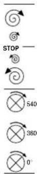
| BITEFFECT | |
| 255 | FAST ROTATION (43 rpm) |
| 193 | SLOW ROTATION (1.1 rph) |
| 191 - 192 | STOP |
| 190 | SLOW ROTATION (1.1 rph) |
| 129 | FAST ROTATION (43 rpm) |
| POSITION 540°127 | |
| 105 | POSITION 450° |
| 84 | POSITION 360° |
| 63 | POSITION 270° |
| 42 | POSITION 180° |
| 21 | POSITION 90° |
| 0 | POSITION 0° |
• EFFECTS MOVEMENT - channel 7
| BITEFFECT | |
| 255 | |
| 0 | 0%-100%; 0.33 sec |
• FROST - channel 8

| BITEFFECT | |
| 255 | FROST INSERTED |
| 0%-100%: 0.12 sec | |
| 0 | FROST EXCLUDED |
• FOCUS - channel 9

| BITEFFECT | |
| 255 | NEAR |
| 0%-100%: 1.11 sec | |
| 0 | DISTANT |
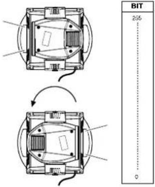
· PAN - channel 10
Operation with option InvertPan ◆ Off
(Tilt conventionally represented at 14% and option Invert Tilt Off)
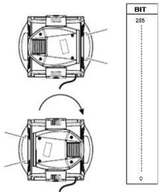
Operation with option InvertPan ↗ On
(Tilt conventionally represented at 14% and option Invert Tilt ◊ Off)
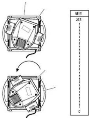
• PAN FINE - channel 11
Operation with option InvertPan ◆ Off
(Tilt conventionally represented at 14% and option Invert Tilt ☐ Off)
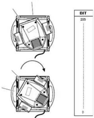
Operation with option InvertPan ♦ On
(Tilt conventionally represented at 14% and option Invert Tilt ☐ Off)
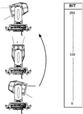
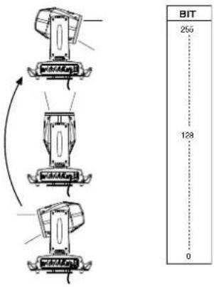
• TILT - channel 12
Operation with option Invert Tilt : Off
(Pan conventionally represented at 0% and option Invert Pan Off)
Operation with option Invert Tilt ☐ On
(Pan conventionally represented at 0% and option Invert Pan Off)
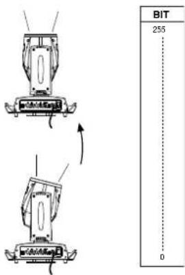
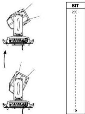
• TILT FINE - channel 13
Operation with option Invert Tilt : Off
(Pan conventionally represented at 0% and option Invert Pan Off)
Operation with option Invert Tilt ☐ On
(Pan conventionally represented at 0% and option Invert Pan Off)
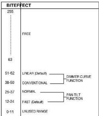
- FUNCTION - channel: 14
flowchart
graph TD
    A["0-11"] --> B["UNUSED RANGE"]
    C["12-24"] --> D["NORMAL"]
    D --> E["CONVENTIONAL"]
    E --> F["LINEAR (Default)"]
    F --> G["DIMMER CURVE FUNCTION"]
    G --> H["PAN-TILT FUNCTION"]
    H --> I["FAST (Default)"]
    I --> J["63"]
    K["25-37"] --> L["NORMAL"]
    L --> M["CONVENTIONAL"]
    M --> N["LINEAR (Default)"]
    N --> O["DIMMER CURVE FUNCTION"]
    O --> P["PAN-TILT FUNCTION"]
    P --> Q["FAST (Default)"]
    Q --> R["63"]
    S["38-50"] --> T["NORMAL"]
    T --> U["CONVENTIONAL"]
    U --> V["LINEAR (Default)"]
    V --> W["DIMMER CURVE FUNCTION"]
    W --> X["PAN-TILT FUNCTION"]
    X --> Y["FAST (Default)"]
    Y --> Z["63"]
    AA["51-62"] --> AB["NORMAL"]
    AB --> AC["CONVENTIONAL"]
    AC --> AD["LINEAR (Default)"]
    AD --> AE["DIMMER CURVE FUNCTION"]
    AE --> AF["PAN-TILT FUNCTION"]
    AF --> AG["FAST (Default)"]
    AG --> AH["63"]
The functions are activated passing through the unused range and staying 5 seconds in necessary level.
- RESET - channel: 15
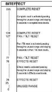
The functions are activated passing through the unused range and staying 5 seconds in necessary level.
• LAMP CONTROL (only with option LAMP DMX On) - channel: 16
IMPORTANT: SHARPY is not provided with hot restrike ignition
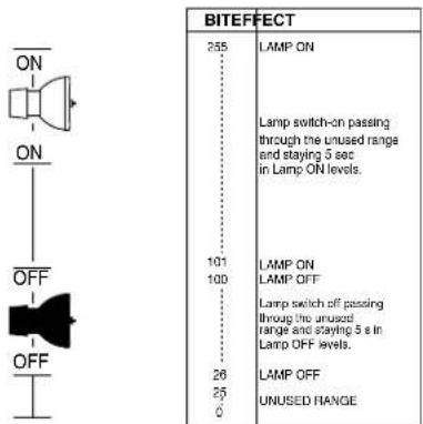
The functions are activated passing through the unused range and staying 5 seconds in necessary level.
TIMING CHANNELS
| Timing Channel | Channel function | |
| 17 | Pan - Tilt time | Pan - Tilt - (Pan fine - Tilt fine) |
| 18 | Colour time | Colour wheel |
| 19 | Beam time | Dimmer - Frost - Prism |
| 20 | Gobo time | Static Gobo |
TIME TABLE
| BIT | Seconds | BIT | Seconds | BIT | Seconds | BIT | Seconds | BIT | Seconds | BIT | Seconds |
| 0 | Full | 43 | 8.6 | 86 | 24 | 129 | 41 | 172 | 58 | 216 | 170 |
| 1 | 0.2 | 44 | 8.8 | 87 | 130 | 173 | 217 | ||||
| 2 | 0.4 | 45 | 9 | 88 | 25 | 131 | 174 | 218 | 180 | ||
| 3 | 0.6 | 46 | 9.2 | 89 | 132 | 42 | 175 | 59 | 219 | ||
| 4 | 0.8 | 47 | 9.4 | 90 | 133 | 176 | 220 | ||||
| 5 | 1 | 48 | 9.6 | 91 | 26 | 134 | 43 | 177 | 221 | 190 | |
| 6 | 1.2 | 49 | 9.8 | 92 | 135 | 178 | 60 | 222 | |||
| 7 | 1.4 | 50 | 10 | 93 | 27 | 136 | 179 | 223 | 200 | ||
| 8 | 1.6 | 51 | 10.2 | 94 | 137 | 44 | 180 | 65 | 224 | ||
| 9 | 1.8 | 52 | 10.4 | 95 | 138 | 181 | 225 | ||||
| 10 | 2 | 53 | 10.6 | 96 | 28 | 139 | 45 | 182 | 226 | 210 | |
| 11 | 2.2 | 54 | 11 | 97 | 140 | 183 | 70 | 227 | |||
| 12 | 2.4 | 55 | 98 | 29 | 141 | 184 | 228 | ||||
| 13 | 2.6 | 56 | 12 | 99 | 142 | 46 | 185 | 75 | 229 | 220 | |
| 14 | 2.8 | 57 | 100 | 143 | 186 | 230 | |||||
| 15 | 3 | 58 | 13 | 101 | 30 | 144 | 47 | 187 | 231 | 230 | |
| 16 | 3.2 | 59 | 102 | 145 | 188 | 80 | 232 | ||||
| 17 | 3.4 | 60 | 14 | 103 | 146 | 189 | 233 | ||||
| 18 | 3.6 | 61 | 104 | 31 | 147 | 48 | 190 | 85 | 234 | 240 | |
| 19 | 3.8 | 62 | 105 | 148 | 191 | 235 | |||||
| 20 | 4 | 63 | 15 | 106 | 32 | 149 | 49 | 192 | 236 | 250 | |
| 21 | 4.2 | 64 | 107 | 150 | 193 | 90 | 237 | ||||
| 22 | 4.4 | 65 | 16 | 108 | 151 | 194 | 238 | ||||
| 23 | 4.6 | 66 | 109 | 33 | 152 | 50 | 195 | 95 | 239 | 260 | |
| 24 | 4.8 | 67 | 110 | 153 | 196 | 240 | |||||
| 25 | 5 | 68 | 17 | 111 | 34 | 154 | 197 | 241 | 270 | ||
| 26 | 5.2 | 69 | 112 | 155 | 51 | 198 | 100 | 242 | |||
| 27 | 5.4 | 70 | 18 | 113 | 156 | 199 | 243 | ||||
| 28 | 5.6 | 71 | 114 | 35 | 157 | 52 | 200 | 110 | 244 | 280 | |
| 29 | 5.8 | 72 | 115 | 158 | 201 | 245 | |||||
| 30 | 6 | 73 | 19 | 116 | 36 | 159 | 202 | 246 | 290 | ||
| 31 | 6.2 | 74 | 117 | 160 | 53 | 203 | 120 | 247 | |||
| 32 | 6.4 | 75 | 20 | 118 | 161 | 204 | 248 | ||||
| 33 | 6.6 | 76 | 119 | 37 | 162 | 54 | 205 | 249 | 300 | ||
| 34 | 6.8 | 77 | 120 | 163 | 206 | 130 | 250 | ||||
| 35 | 7 | 78 | 21 | 121 | 38 | 164 | 207 | 251 | 310 | ||
| 36 | 7.2 | 79 | 122 | 165 | 55 | 208 | 140 | 252 | |||
| 37 | 7.4 | 80 | 123 | 166 | 209 | 253 | |||||
| 38 | 7.6 | 81 | 22 | 124 | 39 | 167 | 56 | 210 | 254 | ||
| 39 | 7.8 | 82 | 125 | 168 | 211 | 150 | 255 | Follow cue Data | |||
| 40 | 8 | 83 | 23 | 126 | 169 | 212 | |||||
| 41 | 8.2 | 84 | 127 | 40 | 170 | 57 | 213 | 160 | |||
| 42 | 8.4 | 85 | 128 | 171 | 214 |
- SAFETY INFORMATION
- EN
- IT
- DE
- ES
- FR
- CONSIGNES DE SÉCURITÉ
- CONTROL PANEL
- Connecting to the control signal line - Fig. 7
- Switching on the projector - Fig. 8
- Functions of the buttons - Using the menu
- USING THE MENU:
- Setting addresses and options with the projector disconnected
- SET UP MENU
- DMX ADDRESS
- NOTE: without the DMX signal the Address (XXX) flashing
- CHANNEL MODE
- FIXTURE ID
- ETHERNET INTERFACE
- Control Protocol
- Repeat on DMX
- Universe
- Custom IP address
- Custom IP mask
- OPTIONS MENU
- LAMP DMX
- SAFETY BLACK OUT
- PAN / TILT
- Invert pan
- Invert tilt
- Swap Pan-Tilt
- Encoder Pan-Tilt
- P/T Homing Mode
- Pan Home Def Pos
- Tilt Home Def Pos
- COLOR
- Fixed wheel short-cut
- Linear Movement
- SHUTTER
- Shutter on error
- DIMMER FILTER TYPE
- - DMX follower
- - Position dependent
- DISPLAY
- SETTING
- INFORMATION MENU
- SYSTEM ERRORS
- FIXTURE HOURS
- Total counter
- Partial counter
- LAMP HOURS
- LAMP STRIKES
- SYSTEM VERSION
- BOARD DIAGNOSTIC
- DMX MONITOR
- FANS MONITOR
- SENSOR STATUS
- NETWORK PARAMS
- MANUAL CONTROL
- LAMP
- RESET
- CHANNEL
- TEST MENU
- TEST
- ADVANCED MENU
- UP LOAD FIRMWARE
- SETUP MODEL
- CALIBRATION
- FACTORY DEFAULT
- MENU LOCKING
- Lamp change - Fig 13
- Lamp regulation - Fig. 14
- CAUTION:
- Periodical cleaning - Fig. 17
- OPTIONAL ACCESSORIES
- DIMENSIONS
- CAUSE AND SOLUTION OF PROBLEMS
- SHARPY
- • TILT - channel 12
- • TILT FINE - channel 13
- - FUNCTION - channel: 14
- - RESET - channel: 15
- • LAMP CONTROL (only with option LAMP DMX On) - channel: 16
Brand : Claypaky
Model : Sharpy C61375
Category : Lighting