
DUOVENT MODULAR DV - Industrial fan Soler & Palau - Free user manual and instructions
Find the device manual for free DUOVENT MODULAR DV Soler & Palau in PDF.


| Product Type | Modular Ventilation Unit |
| Brand | Soler & Palau |
| Model | DUOVENT MODULAR DV |
| Dimensions (H x W x D) | 300 x 400 x 200 mm |
| Weight | 5.5 kg |
| Power Supply | 230 V ~ 50 Hz |
| Max Airflow | 250 m³/h |
| Noise Level | 35 dB(A) at low speed |
| Motor Type | EC motor with energy-saving |
| Control Interface | Integrated electronic controller |
| Filter Type | G4 pre-filter (washable) |
| Installation | Wall or ceiling mount |
| Duct Connection | 125 mm diameter |
| Protection Class | IP44 (splash-proof) |
| Energy Efficiency Class | A+ (ErP ready) |
| Operating Temperature | -10°C to +40°C |
| Maintenance | Clean filters every 3 months; check ducts |
| Safety Features | Overheat protection, motor thermal protection |
| Spare Parts Availability | Filters, motors, controllers available |
| Warranty | 2 years (subject to conditions) |
Frequently Asked Questions - DUOVENT MODULAR DV Soler & Palau
User questions about DUOVENT MODULAR DV Soler & Palau
0 question about this device. Answer the ones you know or ask your own.
Ask a new question about this device
Download the instructions for your Industrial fan in PDF format for free! Find your manual DUOVENT MODULAR DV - Soler & Palau and take your electronic device back in hand. On this page are published all the documents necessary for the use of your device. DUOVENT MODULAR DV by Soler & Palau.
USER MANUAL DUOVENT MODULAR DV Soler & Palau
natural_image
Illustration of five industrial container units arranged in a row, with no visible text or symbols.INSTRUCTION MANUAL
DUOVENT®MODULAR DV/RV ErP2018
Ventilation units with heat recuperation
Contents
1. General 3
1.1 Introduction.... 3
1.2 Warranty.... 3
1.3 Safety regulations.... 4
2. General 4
3. Technical data 4
3.1 Manufacturing label and information labels 4
3.2 Air flow directions 9
3.3 Basic dimensions....10
3.4 General technical data....13
3.5 Operation conditions....14
3.6 Declaration of conformity 15
4. Transport, storage, acceptance....15
5. Installation....17
5.1 Place of installation....17
5.1.1 Distances from building structures (service space) 17
5.1.2 How to store the unit at the destination....19
5.2 Installation procedure and connection to HVAC distribution lines 19
5.2.1 Safety instructions for installation 19
5.2.2 Air connection 19
5.2.3 Connection of electric heater 24
5.2.4 Water heater connection 26
5.2.5 Water cooler connection 28
5.2.6 Direct evaporator connection....29
5.2.7 Connection of condensate drain....29
5.2.8 Bypass and mixing flap of MODULAR DV 31 units ....31
5.2.9 Mixing flap of MODULAR RV units 32
5.2.10 Inlet and outlet flap.... 33
5.2.11 Basic accessories 33
5.2.11.1 Condensate traps 33
5.2.11.2 Regulation unit for ESU water heater or ESUCH water cooler.... 33
6. Electrical installation 35
6.1 Connection of electric heater 35
6.2 Instrumentation and control system....35
6.2.1 Digireg ^ digital control system 35
6.2.2 Temperature control 36
6.2.3 Installation....37
6.2.4 Technology scheme of Digireg® I&C systems 37
6.2.5 Control 39
7. Commissioning 39
7.1 Installation and connection check....39
7.2 Trial operation....39
8. Operation and maintenance....40
8.1 Safety instructions for operation and maintenance....40
8.2 Equipment service 40
8.2.1 Replacement and maintenance of filters....40
8.2.2 Replacement and maintenance of fans 41
8.2.3 Maintenance of recuperation plate exchanger 43
8.2.4 Maintenance of regeneration rotation 43
8.2.5 Service switch 45
8.2.6 Service accesses 45
8.2.7 Periodic inspections....45
8.2.8 Spare parts 45
9. Decommissioning and recycling 45
9. Warranty....46
1. GENERAL
1.1 INTRODUCTION
This manual is intended for ventilation units with heat recuperation DUOVENT® MODULAR DV and RV. Its purpose is to provide as much information as possible for the safe installation, commissioning and use of this equipment. Due to the fact that our products are constantly evolving, we reserve the right to change this manual without prior notice.
1.2 WARRANTY
We do not guarantee the suitability of the devices for special purposes, the determination of suitability is fully in the com petence of the customer and the designer. The warranty for the devices is in accordance with valid legal regulations. The warranty is only valid if all installation and maintenance instructions, including protection, are observed. The warranty covers manufacturing defects, material defects or malfunctions of the device.
The warranty does not cover defects caused by:
- Improper use and design
- Improper handling (does not apply to mechanical damage)
– During transport (compensation for damage caused during transport must be claimed from the carrier) - Incorrect installation, incorrect electrical connection or protection
- Incorrect operation
– Unprofessional intervention in the device
– Disassembling the device
– Use in unsuitable conditions or in an unsuitable manner - Wear and tear caused by normal use
– Third party intervention
– Due to a natural disaster - Frost-damaged water exchanger parts are not covered by the warranty if it has been demonstrably proven that the unit was in operation without heating water at min. design temperature or during shutdown of the boiler circuit
When claiming the warranty, it is necessary to submit a report containing:
– Data on the complaining company
– Date and number of the sales document
– Exact specification of the defect
– Wiring diagram and fuse details
– Measured values when starting the device
- Voltage
- Current
– Air temperature
-Air flow
The warranty repair is carried out in principle at the discretion of S&P UK Ventilation Systems Ltd at the company's service centre or at the installation site. The method of eliminating the defect is solely at the discretion of the service company S&P UK Ventilation Systems Ltd. The complaining party will receive a written statement on the result of the complaint. In the event of an unjustified complaint, the complaining party pays all costs of its implementation.
Warranty conditions
The device must be installed by a professional air handling service company. The DUOVENT® MODULAR DV/RV device, including the DVAV, DCAV, DCOP control system, must be put into operation exclusively by the Seller or a person designated by the Seller (StartPack service). Failure to comply with this condition will result in the termination of the Buyer's rights from defective performance and from the Quality Warranty. Detailed terms are specified in the Seller's Complaint Procedure. The electrical connection must be made by a specialist electrical company. Installation and location of the device must be unconditionally performed in accordance with ČSN 33 2000-4-42 (IEC 364-4-42). The device must be subjected to an initial electrical inspection according to ČSN 33 1500. The device must be regulated to the designed air-conditioning parameters. When starting the device, it is necessary to measure the above-specified values and make a record of the measurement, confirmed by the company putting the device into operation. In the event of a complaint about the equipment, it is necessary to submit a record of the above-mentioned parameters from commissioning together with the declaration protocol together with the initial revision, which the operator acquires within the commissioning and maintenance of the electrical installation.
During the operation, it is necessary to perform regular inspections of electrical equipment within the deadlines according to ČSN 33 1500 and inspection, maintenance and cleaning of air-conditioning equipment. It is necessary to keep a "Maintenance and inspection book" for the maintenance and service of the device, for which the device operator is responsible.
When taking over the device and unpacking it from the transport packaging, the customer is obliged to perform the following inspections. It is necessary to check the integrity of the device, as well as whether the delivered device exactly agrees with the ordered device. It is always necessary to check whether the label and identification data on the transport packaging, equipment or engine correspond to the designed and ordered parameters. Due to the continuous technical development of the equipment and changes in technical parameters reserved by the manufacturer, and the time lag between the project and the implementation of own sales, fundamental differences in the parameters of the equipment at the date of sale cannot be ruled out. The customer is obliged to inform the manufacturer or supplier about such changes before ordering the goods. Subsequent complaints cannot be taken into account.
1.3 SAFETY REGULATIONS
Adherence to these instructions should not pose any safety, health or environmental risks in accordance with EC directives (CE marked). The same applies to other products used in the device or during installation. Consider the following warnings:
- Observe the safety instructions to prevent damage to the device or personal injury.
- The technical information in this manual must not be changed.
- It is forbidden to interfere with the motor of the device.
- In order for the device to comply with EC directives, the device must be connected to the mains in accordance with the applicable regulations.
- The device must be installed in such a way that under normal operating conditions it cannot come into contact with any moving part and / or live part.
- The device complies with the applicable regulations for the operation of electrical equipment.
- Always disconnect the device from the power supply before carrying out any work on it.
- Appropriate tools must be used when handling or maintaining the device.
- The device must only be used for the purposes for which it is intended.
- This appliance is not intended for use by children under 8 years of age and persons with reduced physical, sensory or mental capabilities, or lack of experience and knowledge, unless they have been given supervision or instruction concerning use of the appliance by a responsible person. The user must ensure that children do not play with the device. Cleaning and maintenance of the appliance must not be carried out by children without supervision.
2. GENERAL
The DUOVENT® MODULAR DV/RV unit is manufactured in accordance with valid Czech and European laws, decrees, standards and technical rules. The unit may only be installed and used in accordance with this documentation. The manufacturer is not liable for damage caused by other uses and the buyer bears all risks. Changes and modifications to the complete product that could affect safety and proper function are prohibited. Installation and operating documentation must be available to the operator and service. It is advisable to place it close to the installed unit.
When disposing of the unit, the relevant environmental and waste disposal regulations must be observed. In the case of final disposal, it is necessary to follow the principles of separate collection. The applicable standards, safety regulations and generally accepted technical rules must be observed during installation, electrical connection, commissioning, repairs and maintenance of the units. Assembly of units, connection of electrical installation, commissioning of the unit, repairs, maintenance and operation may be performed only by a natural or legal person with a valid authorization. The current version of this manual is available at www.solerplau.co.uk.
3. TECHNICAL DATA
3.1 MANUFACTURING LABEL AND INFORMATION LABELS
Each unit is provided with a manufacturing label, which contains the basic data needed to identify the device. The label is usually located on the front of the unit or on the connection side of the heat exchanger parts.
| TYPE | Duovent Modular DV 12000 DCB DXr MX KL F7/M5 DVAV AV | |||||
| SERIAL NUMBER | 1299/2019 | WEIGHT | 1355 | kg | ||
| MANUFACTURED | 04/2019 | HEAT LOSS DCA | 45/35 | °C | ||
| REF | 01BB190098 | HEAT LOSS DCC | 10035 | °C | ||
| MAX OPERATING TEMP | 40 | °C | TOTAL max | 1660 | W | |
| MAX AIRFLOW | 12000 | m3/h | VOLTAGE | Um | 4X400 V ~ 50 Hz | |
| MAX EXT PRESSURE | 350 | Pa | CURRENT | In | 14,5 | A |
| MAX EXT PRESSURE | MAX TEMP 110°C MAX PRESSURE 1,6MPa | |||||
| PARAMETERS FOR WATER HEATER | ||||||
Key to distinguish the variants of DUOVENT® MODULAR DV recuperation units ("TYPE" field on the label): (DUOVENT® MODULAR DV = unit equipped with counter-current recuperation exchanger)
| DUOVEN1 | MODULAR | DV | 10 | 100 | DCA | DCC | MX | KL | F7 | /M5 | DVAV | AV | PRV |
| 1 | 2 | 3 | 4 | 5 | 6 | 7 | 8 | 9 |
1 - unit size - 8500, 10100, 12000, 14500
2 - heater type:
DI - electric
DCA - water, temperature drop on water 80/60 °C
DCB - water, temperature drop on water 45/35 °C
3 - water cooler type:
DCC - water, temperature for gradient on water 6/12 °C
DX - direct evaporator for refrigerant R410A, evaporating temperature 6 °C
(for a direct evaporator, it is always necessary to specify the type of refrigerant, the required capacity and the division of the refrigeration capacity into sections according to the type of condensing unit used). For evaporation units used for reverse operation with the thermal pump this fact must be specified in the order.
DXr - evaporator in connection for reverse operation (cooling/heating), refrigerant R410A
4 - MX - mixing damper with preparation for mounting the actuator (if the unit is equipped with MaR system the actuator is included in the delivery)
C - mixing damper enabling 100 % air circulation with preparation for mounting the actuator (if the unit is equipped with MaR system the actuator is included in the delivery )
5 - KL - inlet and outlet damper with preparation for mounting the actuator (if the unit is equipped with the MaR system, the actuator is part of the delivery)
6 - filter filtration class at the fresh air inlet/at the exhaust from the ventilated space (G4 - F9)
7 - type of control system:
D - Digireg ^
8 - air flow control type:
VAV - variable air flow
CAV - constant air flow
COP - constant static pressure supplied to the HVAC piping network
9 - position of the nozzles with respect to the operating side - AV or AV2
10 - RDP - design of the unit for process ventilation (PROCESS) - for applications excluded from the effectiveness of EC Regulation No. 1253/2014, as well as for applications and markets outside the validity of EC Regulation No. 1253/2014
Order examples
DUOVENT®MODULAR DV 14500 DI DX MX KL G4+F7/F7 DVAV AV2
Unit of size 14500 with electric heater, direct evaporation unit only for cooling, bypass and mixing flap, two-stage filtering at inlet G4+F7, single-stage filtering at outlet F7, I&C system Digireg® with VAV, neck position AV2.
DUOVENT®MODULAR DV 8500 DCA M5/G4 DVAV AV PRV
Unit of size 8500 with water heating 80/60 °C, inlet filter M5, exhaustion filter G4, I&C system Digireg® with VAV, neck position AV, unit in process arrangement not complying EC regulation no. 1253/2014.
Key to distinguish the variants of DUOVENT® MODULAR RV recuperation units („TYPE“ field on the label): (DUOVENT® MODULAR RV = unit equipped with rotation regeneration exchanger)
| DUOVENTMODULARRV | 10 | 100 | T | DCADCCMX | KL | F7/M5 | DVAV | AV |
| 1 | 2 | 3 | 4 | 5 | 6 | 7 | 8910 |
1 - unit size - 8500, 10100, 12000, 14500
2 - type of regeneration exchanger rotor:
T - temperature
E - enthalpy
S - sorption
3 - heater type:
DI - electric
DCA - water, temperature drop on water 80/60 °C
DCB - water, temperature drop on water 45/35 °C
4 - water cooler type:
DCC - water, temperature for gradient on water 6/12 °C
DX - direct evaporator for refrigerant R410A, evaporating temperature 6 °C
(for a direct evaporator, it is always necessary to specify the type of refrigerant, the required capacity and the division of the refrigeration capacity into sections according to the type of condensing unit used). For evaporation units used for reverse operation with the thermal pump this fact must be specified in the order.
DXr - evaporator in connection for reverse operation (cooling/heating), refrigerant R410A
5 - MX - mixing damper with preparation for mounting the actuator (if the unit is equipped with MaR system the actuator is included in the delivery)
C - mixing damper enabling 100 % air circulation with preparation for mounting the actuator (if the unit is equipped with MaR system the actuator is included in the delivery )
6 - KL - inlet and outlet damper with preparation for mounting the actuator (if the unit is equipped with the MaR system, the actuator is part of the delivery)
7 - filter filtration class at the fresh air inlet/at the exhaust from the ventilated space (G4 – F9)
8 - type of control system:
D - Digireg ^®
9 - air flow control type:
VAV - variable air flow
CAV - constant air flow
COP - constant static pressure supplied to the HVAC piping network
10 - position of the nozzles with respect to the operating side - AV or AV2
Order examples
DUOVENT®MODULAR RV 14500 T DI DX MX KL G4+F7/F7 DVAV AV2
Unit of size 14500 with regenerator temperature rotor, electric heater, direct evaporation unit only for cooling, mixing flap, two-stage filtering at inlet G4+F7, single-stage filtering at outlet F7, I&C system Digireg® with VAV, neck position AV2.
DUOVENT®MODULAR RV 8500 S DCA F7/M5 DVAV AV
Unit of size 8500 with sorption regenerator rotor, water heater 80/60 °C, inlet filter F7, exhaust filter M5, I&C system Digireg® with VAV, neck position AV.
In addition, the unit is equipped with labels to identify the internal arrangement of functions:

WATER/ELECTRIC HEATER

WATER/DIRECT COOLER

FAN

FILTER
The unit is also equipped with labels with warnings:
HEATING/COOLING MEDIA INPUT

HEATING/COOLING MEDIA OUTPUT

NOTICE ON LOCATION OF FAULT RESET BUTTON OF EL. HEATER
CONDENSATE DRAIN

NOTICE ON LOCATION OF THE CONDENSATE DRAINAGE NECK IN THE BOTTOM OF THE UNIT
IMPORTANT NOTICE
If the prescribed protections are not connected in accordance with S&P instructions, the warranty will not be valid.
NOTICE ON CONNECTION OF FAN MOTOR PROTECTIONS
IMPORTANT WARNING!
The sensor is located in the thermal area

ATTENTION!
For proper frost protection of the exchanger, it is necessary to properly insulate the thermal sensor on the return side of the exchanger.
To start the unit, it is necessary to vent the system. The valves are inside the units on the water exchanger manifold.
WARNING OF THE NECESSITY OF INSULATION OF THE ANTIFREEZE PROTECTION CONTACT SENSOR

| Air Flow Measurement | |
| V = K.√(Δp) | Δp (Pa)V (m3/h) |
| Fan type | K (-) |
| RH25V, R3G250, | ) |
| RH25C K3G250 | 60 |
| RH31C | 76 |
| R3G310 | 95 |
| RH35C | 116 |
| RH40C | 121 |
| RH45C | 154 |
WARNING - DO NOT OPERATE THE UNIT WHILE CONSTRUCTION WORK IN PROGRESS
AIR FLOW CALCULATION PLATE LOCATED AT FAN SUCTION PRESSURE ORIFICE PORT


WARNING LABELS
Labels to identify the type of air stream:

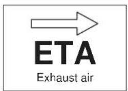

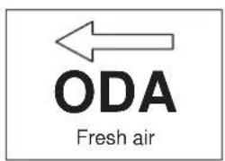
3.2 DIRECTION OF AIR FLOW IN DUOVENT® MODULAR DV/RV UNITS:

flowchart
graph TD
    subgraph DUOVENT MODULAR DV UNITS
        A1["EXHAUST AIR ETA"] --> B1["CIRCULATION AIR RCA"]
        B1 --> C1["SUPPLY AIR SUP"]
        D1["FRESH AIR ODA"] --> E1["WASTE AIR EHA"]
    end
    subgraph DUOVENT MODULAR DV UNITS
        F1["FRESH AIR ODA"] --> G1["CIRCULATION AIR RCA"]
        G1 --> H1["SUPPLY AIR SUP"]
        I1["EXHAUST AIR ETA"] --> J1["CIRCULATION AIR RCA"]
        J1 --> K1["SUPPLY AIR SUP"]
        L1["WASTE AIR EHA"]
    end

flowchart
graph LR
    A["EXHAUST AIR ETA"] --> B["CIRCULATION AIR RCA"]
    B --> C["SUPPLY AIR SUP"]
    D["WASTE AIR EHA"] --> E["FRESH AIR ODA"]
    style A fill:#f9f,stroke:#333
    style B fill:#9cf,stroke:#333
    style C fill:#66f,stroke:#333
    style D fill:#ff9,stroke:#333
    style E fill:#ff9,stroke:#333

flowchart
graph TD
    A["WASTE AIR EHA"] --> B["EHA"]
    B --> C["EXHAUST AIR ETA"]
    C --> D["CIRCULATION AIR RCA"]
    D --> E["SUPPLY AIR SUP"]
    F["FRESH AIR ODA"] --> G["Supply Air Sup"]
    style A fill:#f9f,stroke:#333
    style B fill:#ccf,stroke:#333
    style C fill:#cfc,stroke:#333
    style D fill:#fcc,stroke:#333
    style E fill:#cff,stroke:#333
3.3 BASIC DIMENSIONS OF DUOVENT® MODULAR DV/RV UNITS
Dimensional diagram of DUOVENT® MODULAR DV 8500 to 14500 units (drawn position of AV2 unit)
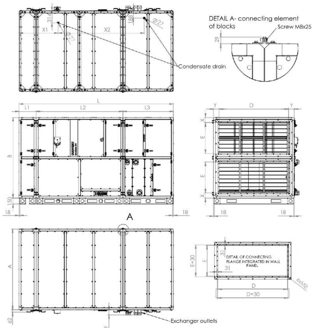
Condensate drain
DETAIL A- connecting element
of blocks
| Type | A[mm] | B[mm] | D[mm] | E[mm] | F[mm] | L[mm] | L1[mm] | L2[mm] | L3[mm] | X[mm] | Y[mm] | X1[mm] | X2[mm] |
| DV 8500 | 1620 | 1620 | 1350 | 600 132 | 3289 | 442 | 1698 | 1149 | 118 | 135.0 | 740 1883 | ||
| DV 10100 | 1777 | 1777 | 1500 | 650 | 132 | 3525 | 442 | 1934 | 1149 | 132 | 138.5 | 858 | 2001 |
| DV 12000 | 1934 | 1934 | 1650 | 700 132 | 3604 | 442 | 1934 | 1228 | 146 | 142.0 | 858 2018 | ||
| DV 14500 | 2091 | 2091 | 1800 | 800 | 132 | 3996 | 442 | 2248 | 1306 | 135 | 145.5 | 1015 | 2233 |
Dimensional diagram of DUOVENT® MODULAR RV 8500 to 14500 units - unit design with mixing flap - in unit code MX or C (drawn position of AV2 unit)

| Type | A[mm] | B[mm] | D[mm] | E[mm] | F[mm] | L[mm] | L1[mm] | L2[mm] | L3[mm] | X[mm] | Y[mm] | X1[mm] | X2[mm] |
| RV 8500 | 1620 | 1620 | 1350 | 600 132 | 2662 | 442 | 1071 | 1149 | 118 | 135 | 978 1019 | ||
| RV 10100 | 1777 | 1777 | 1500 | 650 | 132 | 2662 | 442 | 1071 | 1149 | 132 | 138.5 | 978 | 1019 |
| RV 12000 | 1934 | 1934 | 1650 | 700 132 | 2819 | 442 | 1149 | 1228 | 146 | 142 | 1017 1075 | ||
| RV 14500 | 2091 | 2091 | 1800 | 800 | 132 | 2897 | 442 | 1149 | 1306 | 135 | 145.5 | 1017 | 1133 |
Dimensional diagram of DUOVENT® MODULAR RV 8500 to 14500 units - unit design without mixing flap - in unit code MX or C (drawn position of AV2 unit)
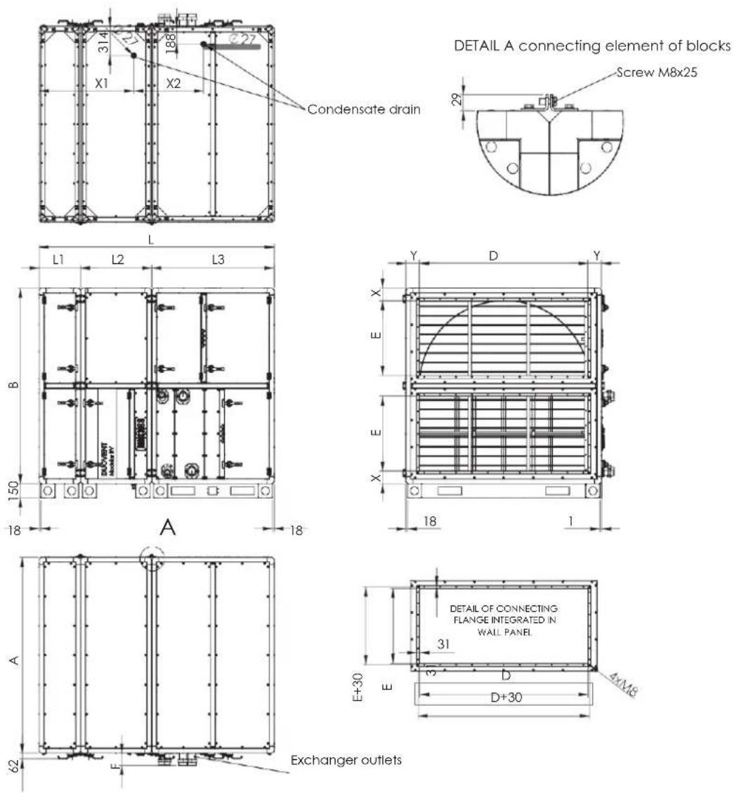
| Type | A[mm] | B[mm] | D[mm] | E[mm] | F[mm] | L[mm] | L1[mm] | L2[mm] | L3[mm] | X[mm] | Y[mm] | X1[mm] | X2[mm] |
| RV 8500 | 1620 | 1620 | 1350 | 600 132 | 2348 | 442 | 757 | 1149 | 118 | 135 | 1011 | 671 | |
| RV 10100 | 1777 | 1777 | 1500 | 650 | 132 | 2348 | 442 | 757 | 1149 | 132 | 138.5 | 1011 | 671 |
| RV 12000 | 1934 | 1934 | 1650 | 700 132 | 2427 | 442 | 757 | 1228 | 146 | 142 | 1011 | 688 | |
| RV 14500 | 2091 | 2091 | 1800 | 800 | 132 | 2505 | 442 | 757 | 1306 | 135 | 145.5 | 1011 | 746 |
3.4 GENERAL TECHNICAL DATA
Detailed technical data of the specific design of the DUOVENT® unit are part of the technical specification of the unit, which is shipped together with the unit. The technical specification is located in the packaging on the inside or outside of the service door of the unit.
The technical specifications include:
- Investor details
– Information on the installation company (or designer)
– Detailed technical data of all components of the unit (fan, recuperator, heater, cooler, filter) - Overall dimensions of the unit and the total weight of the unit, including accessories
- Dimensional diagram of the unit, including a representation of the service space
– Specification of I&C scope, if it is part of the delivery
– Description of scope of atypical unit variant
DUOVENT® MODULAR DV:
| Type | Nominal flow[m3/h] | voltage[V/Hz] | Inlet/exhaust fan | heater | cooler power*[kW] | efficiency*[%,] | unit max. air flow**[m3/h] | control systemDigireg® | weight***[kg] | ||
| max. input power[W] | current[A] | power*[kW] | current[A] | ||||||||
| 8500 | 8500 | 3×400V 50Hz | 4178/2952 | 6/4.3 | - | - | - | 94.3 | 9000 | M3-Vx | 860–950 |
| 8500 DCA | 64.2 | - | - | ||||||||
| 8500 DCB | 45.5 | - | - | ||||||||
| 8500 DCA DCC | 64.2 | - | 65.8 | ||||||||
| 8500 DCA DX | 64.2 | - | 69.9 | ||||||||
| 8500 DI | 30.0 | 43.3 | - | M3-E36 | |||||||
| 10100 | 10100 | 3×400V 50Hz | 4907/3763 | 7.1/5.4 | - | - | - | 94.6 | 11500 | M3-Vx | 1025–1138 |
| 10100 DCA | 79.5 | - | - | ||||||||
| 10100 DCB | 56.0 | - | - | ||||||||
| 10100 DCA DCC | 79.5 | - | 81.7 | ||||||||
| 10100 DCA DX | 79.5 | - | 84.8 | ||||||||
| 10100 DI | 45.0 | 65.0 | - | M3-E72 | |||||||
| 12000 | 12000 | 3×400V 50Hz | 5738/4297 | 8.3/6.2 | - | - | - | 94.3 | 13500 | M3-Vx | 1188–1321 |
| 12000 DCZ | 94.5 | - | - | ||||||||
| 12000 DCB | 65.0 | - | - | ||||||||
| 12000 DCA DCC | 94.5 | - | 98.0 | ||||||||
| 12000 DCA DX | 94.5 | - | 99.3 | ||||||||
| 12000 DI | 45.0 | 65.0 | - | M3-E72 | |||||||
| 14500 | 14500 | 3×400V 50Hz | 6738/5075 | 9.8/7.3 | - | - | - | 92.3 | 16500 | M3-Vx | 1469–1631 |
| 14500 DCA | 116.0 | - | - | ||||||||
| 14500 DCB | 79.5 | - | - | ||||||||
| 14500 DCA DCC | 116.0 | - | 121.0 | ||||||||
| 14500 DCA DX | 116.0 | - | 119.0 | ||||||||
| 14500 DI | 60.0 | 86.6 | - | M3-E72 | |||||||
* at nominal air flow, t_0 = -12^ / 90% r.h., t_1 = 22^ / 50% r.h., t_2 = 35^ / 35% r.h. (SUMMER)
** for arrangement - inlet: filter F7 + DV + DCB, outlet: filter M5 + DV
*** in relation to the unit accessory (without I&C)
Water cooler power DCC for t_e = 35^ C / 35% r.h., t_w = 6/12^ C . Water heater power DCA for t_e = 10^ C , t_w = 80/60^ C .
Water heater power DCB for t_e = 10^ , t_w = 45 / 35^ . Direct evaporating unit power DX for R410A coolant, t_u = 35^ / 35% r.h., t_yp = 6^ .
DUOVENT® MODULAR RV:
| Type | Nominal flow[m3/h] | voltage[V/Hz] | Inlet/exhaust fan | heater | cooler power*[kW] | efficiency*[%] | unit max. air flow**[m3/h] | control systemDigireg® | weight***(without MX)[kg] | weight***(with MX)[kg] | ||
| max. input power[W] | current[A] | power*[kW] | current[A] | |||||||||
| 8500 | 7800 | 3×400V50Hz | 3653/2521 | 5.3/3.6 | - | - | - | 75.7 | 9000 | M3-Vx | 832to917 | 860to951 |
| 8500 DCA | 61.1 | - | - | |||||||||
| 8500 DCB | 43.1 | - | - | |||||||||
| 8500 DCA DCC | 61.1 | - | 62.2 | |||||||||
| 8500 DCA DX | 61.1 | - | 66.2 | |||||||||
| 8500 DI | 30.0 | 43.3 | - | M3-E36 | ||||||||
| 10100 | 9300 | 3×400V50Hz | 4228/3152 | 6.1/4.6 | - | - | - | 76.2 | 11500 | M3-Vx | 965to1072 | 996to1109 |
| 10100 DCA | 75.7 | - | - | |||||||||
| 10100 DCB | 53.1 | - | - | |||||||||
| 10100 DCA DCC | 75.7 | - | 77.3 | |||||||||
| 10100 DCA DX | 75.7 | - | 80.9 | |||||||||
| 10100 DI | 45.0 | 65.0 | - | M3-E72 | ||||||||
| 12000 | 11500 | 3×400V50Hz | 5183/3780 | 7.5/5.5 | - | - | - | 75.9 | 13500 | M3-Vx | 1176to1302 | 1224to1357 |
| 12000 DCA | 92.2 | - | - | |||||||||
| 12000 DCB | 63.3 | - | - | |||||||||
| 12000 DCA DCC | 92.2 | - | 95.2 | |||||||||
| 12000 DCA DX | 92.2 | - | 96.9 | |||||||||
| 12000 DI | 45.0 | 65.0 | - | M3-E72 | ||||||||
| 14500 | 13600 | 3×400V50Hz | 6129/4531 | 8.9/6.6 | - | - | - | 75.1 | 16500 | M3-Vx | 1389to1544 | 1441to1604 |
| 14500 DCA | 111.0 | - | - | |||||||||
| 14500 DCB | 76.4 | - | - | |||||||||
| 14500 DCA DCC | 111.0 | - | 115.0 | |||||||||
| 14500 DCA DX | 111.0 | - | 115.0 | |||||||||
| 14500 DI | 60.0 | 86.6 | - | M3-E72 | ||||||||
* at nominal air flow, t_e = -12^ C/90% r.h., t_i = 22^ C/50% r.h., t_e = 35^ C/35% r.h. (SUMMER), temperature rotor
** for arrangement - inlet: filter F7 + RV + DCB, outlet: filter M5 + RV
*** in relation to the unit accessory (without I&C)
Water cooler power DCC for t_e = 35^ C / 35% r.h., t_w = 6/12^ C . Water heater power DCA for t_e = 10^ C , t_w = 80/60^ C .
Water heater power DCB for t_c = 10^ , t_w = 45 / 35^ . Direct evaporating unit power DX for R410A coolant, t_c = 35^ / 35% r.h., t_vyp = 6^ .
3.5 OPERATION CONDITIONS
The unit can be used in rooms normal according to IEC 60364-5-51, resp. ČSN 332000-5-51 ed. 3, ČSN 332000-1 ed.2. The ambient temperature must be between -20 and +40 °C.
The unit can transport air without solid, fibrous, sticky, aggressive chemical and explosive additives. The maximum permissible supply air temperature must not exceed +40 °C. The maximum humidity of the air flowing through the unit is 17 g/kg s.v. (84 % r.h. at 25 °C).
If, due to the immediate climatic conditions, the humidity of the outdoor intake air reaches 100 % r.h. (wet steam), it is at the operator's discretion whether to keep the unit running with the risk of temporary separation of moisture on the internal parts of the unit (eg filters, flaps,...). This humidity cannot be the subject of a complaint.

CAUTION!
For units with a direct evaporator (marked DX and DXr in the unit code), the design air flow through the unit must be observed when operating the direct evaporator/condenser. It is acceptable to reduce the flow in cooling and heating mode by a maximum of 20 % of the design air flow. For proper operation of the direct evaporator, it is necessary to observe the necessary heat or cold consumption from the heat exchange surface of the evaporator/condenser. If the design amount of energy is not consumed, the condensing unit / heat pump may report a fault in the pressure protections (LP, HP) of the cooling circuit and the condensing unit / heat pump may cycle in ON/OFF mode.

CAUTION!
Units with direct evaporator (marked DX and DXr in the unit code) must be equipped with a mixing flap (MX in the unit code) ensuring as needed the min. temperature at the condenser/evaporator inlet temperature of +10 °C.
3.6 DECLARATION OF CONFORMITY
This type of product was tested by the Authorized Person of EZU Prague, and a certificate was issued for it. For a unit of the above type, within the meaning of Act No. 22/1997 Coll. as amended, issued a "Declaration of Conformity".
4. TRANSPORT, STORAGE, ACCEPTANCE
On the loading surface of the vehicle, the unit must be sufficiently secured against slipping and tipping over.
The unit is wrapped in PE foil and placed on transport beams. The unit is fixed to the transport beam by means of sheet metal clamps and screws. The unit is always shipped in 3 separate blocks. The connection of individual blocks is carried out only after transport to the destination in the building (air conditioning engine room or roof).

CAUTION!
The holes in the frame and legs are not intended for the unit hinging.
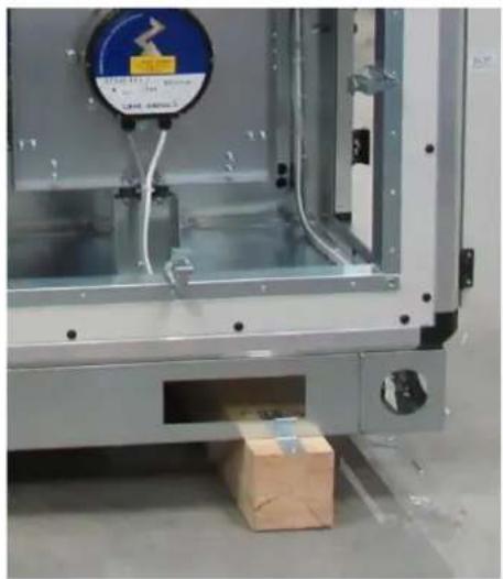
natural_image
Interior view of an industrial machine with a warning label and cardboard box on the floor (no readable text or symbols)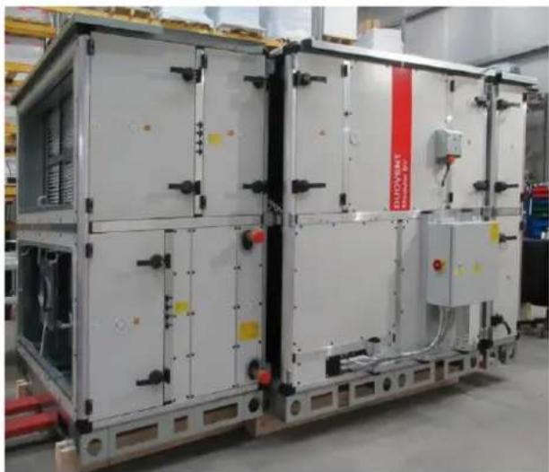
natural_image
Industrial equipment unit with large white panels and black connectors, no visible text or symbols on the main structure.detail of the transport beam expedition blocks of DUOVENT® MODULAR DV/RV units
When loading and unloading with a forklift, lift the unit by attaching it to the bottom edge of the base frame or through pre-prepared holes in the unit frame. When transporting the unit, it is necessary to support the unit on the underside over the entire surface to prevent damage and to pay attention to the condensate outlet opening on the underside of the unit.
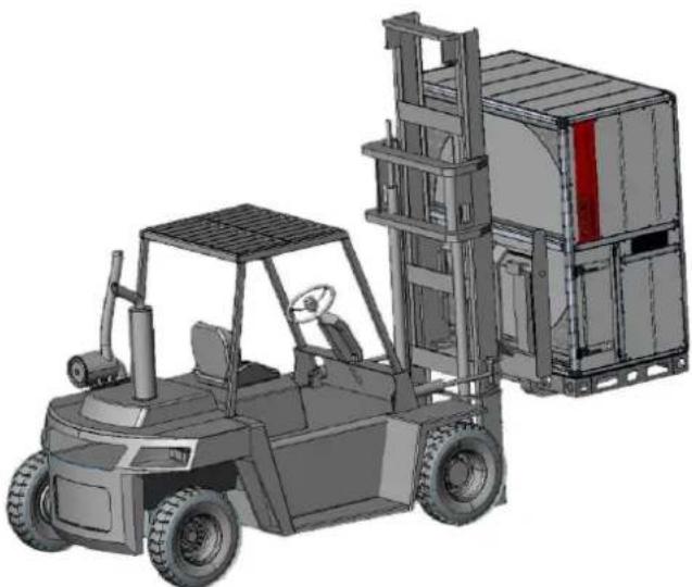
natural_image
3D rendering of a forklift carrying a shipping container (no text or symbols visible)transport of the DUOVENT® MODULAR unit block using a forklift

natural_image
3D mechanical assembly diagram showing structural components and mounting brackets (no text or symbols)attaching the DUOVENT ^® MODULAR unit block to the bottom edge of the base frame

natural_image
3D mechanical assembly diagram showing structural components and mounting brackets (no text or symbols)attaching the DUOVENT® MODULAR unit block behind the holes in the lower base frame

natural_image
Technical diagram of a mechanical assembly with vertical and horizontal components, no visible text or symbolsthe fork length of the forklift truck must always be below the entire width of the unit
When lifting with a crane, it is necessary to pass the ropes under the unit so that they do not slip. The unit can be manipulated only by supporting or tying behind the floor of the unit - the unit cannot be lifted behind the ceiling of the unit or other parts (eg HVAC flanges, heat exchanger outlets, etc.). It is necessary to ensure the balance of the transported unit block. The ropes above the unit must be stretched to prevent damage.

CAUTION!
The unit shall not be transported above persons!

natural_image
Line drawing of a rectangular container being lifted by a crane hook (no text or symbols)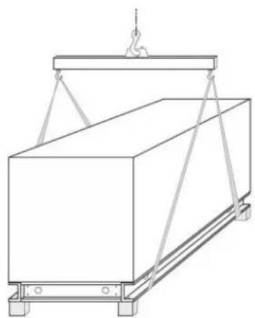
natural_image
Line drawing of a rectangular container being lifted by a crane hook (no text or symbols)possible ways of tying the unit block - using passports or using a crossbar
The units must be stored in dry and dust-free areas where the ambient temperature does not fall below +5 °C. The unit must be protected during storage against mechanical damage, dirt and corrosion caused by permanent condensation of water vapour on the surface of the unit. During storage, it is necessary to protect the units against snow, rain and other weather conditions (store in a covered warehouse).
When accepting the unit, it is necessary to check whether the product was delivered in the agreed design and extent, whether it was not damaged during transport, whether there is no condensed water under the plastic wrap (if there is moisture under the packaging, unpack the unit and dry in a covered dry place). In case of damage during transport, the transferee must record the extent of damage in the Delivery Note, obtain and send photo documentation to S&P UK Ventilation Systems Ltd. Failure to comply with this procedure exposes the transferee to the risk of rejection of the complaint by S&P UK Ventilation Systems Ltd.
5. INSTALLATION
The unit can only be installed by a professional installation company authorized in accordance with the Trade Licensing Act.
5.1 PLACE OF INSTALLATION
The unit can only be installed in accordance with the "Environmental Protocol", in which the characteristics of all devices that can be placed in this space are clearly defined, and it is not possible to place devices that would affect these conditions in any way. The unit has a limited load capacity and is certainly not intended for storing and depositing any materials, especially objects of considerable weight. This could deform the housing of the unit or severely damage it. These damages are not covered by the warranty. After connecting the unit to the HVAC piping, it is necessary to check the insulation of the HVAC piping in parts with a risk of condensation. Condensate formed in the air duct can, in unfavourable conditions, spill into the interior of the unit, where it is not separated and may flow out of the unit. The result of this process can be damage to adjacent building structures.
5.1.1 DISTANCES FROM BUILDING STRUCTURES (SERVICE SPACE)
Observe the minimum recommended distances from all obstacles to ensure easy maintenance and operation of the unit. If the unit is fitted with Digireg® control system, it is necessary to ensure free space from the system distribution box of at least 800 mm and the space for free opening of the doors. It is also necessary to ensure distances on the side of connecting the air duct to the unit. All media connections and MaR, or other constructions, must not prevent the full opening of all openings (doors) used for operation and maintenance of the unit. Unless otherwise stated in the order, the control system switchboard will always be located on the operating side of the unit (see figures below). The atypical location of the switchboard must be specified in the order. There must be free access to the distribution box; the quality of access must not be impaired by small or protruding objects in the way, slippery floors, etc. The distribution box must not be surrounded in such a way as to impair the transfer of heat to the surrounding area. If it is allowed to store and store objects in the vicinity of the switchboard, a minimum space must be marked, which must remain free. It is not allowed to place any objects on the distribution box.
Minimum service space of DUOVENT® MODULAR DV:
| Size | A [mm] | B [mm] | L [mm] | S [mm] |
| DV 8500 | 1620 | 1620 | 3289 | 1700 |
| DV 10100 | 1777 | 1777 | 3525 | 1800 |
| DV 12000 | 1934 | 1934 | 3604 | 2000 |
| DV 14500 | 2091 | 2091 | 3996 | 2150 |

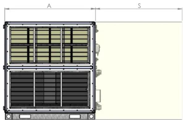
I&C control box – Digireg ^®
Minimum service space of DUOVENT® MODULAR RV units - unit design with mixing flap (MX or C in code):
| Size | A [mm] | B [mm] | L [mm] | S [mm] |
| RV 8500 | 1620 | 1620 | 2662 | 1700 |
| RV 10100 | 1777 | 1777 | 2662 | 1800 |
| RV 12000 | 1934 | 1934 | 2819 | 2000 |
| RV 14500 | 2091 | 2091 | 2897 | 2150 |


I&C control box - Digireg®
Minimum service space of DUOVENT® MODULAR RV units - unit design without mixing flap (MX or C in code):
| Size | A [mm] | B [mm] | L [mm] | S [mm] |
| RV 8500 | 1620 | 1620 | 2348 | 1700 |
| RV 10100 | 1777 | 1777 | 2348 | 1800 |
| RV 12000 | 1934 | 1934 | 2427 | 2000 |
| RV 14500 | 2091 | 2091 | 2505 | 2150 |
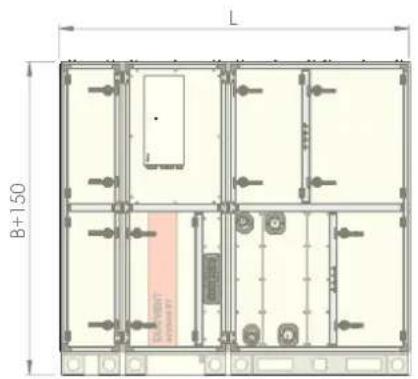

I&C control box - Digireg®
5.1.2 HOW TO STORE THE UNIT AT THE DESTINATION
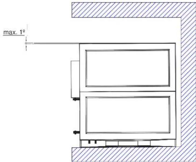
The unit is intended for mounting on the floor or roof of a building in a vertical position (positions marked in the unit code "xV"). The unit must be placed on a solid base with a maximum limit deviation of 3 mm per 2 m of length. The unit must be supported by an anti-vibration rubber pad with a minimum hardness of 50° Sha. The pad serves to reduce the transmission of the dynamic effects of the unit to the substrate and at the same time to reduce the noise emissions emitted by the vibrating parts of the unit. Washers are not included with the unit. The unit must be positioned in the slope of max. 1° to the condensate drains at the operation side.
5.2 INSTALLATION PROCEDURE AND CONNECTION TO HVAC DISTRIBUTION LINES
All required dimensions and weights of the unit and accessories can be found in the "Technical data" chapter.
5.2.1 SAFETY INSTRUCTIONS FOR INSTALLATION
Follow all safety recommendations to prevent damage to the unit or personal injury. The technical characteristics of this manual must not be changed. The motors of the unit must not be changed. The unit can be connected to a three-phase AC mains supply 400 V/50 Hz or single-phase 230 V/50 Hz AC networks according to the specific design of the unit. For installation in accordance with EC regulations, DUOVENT® MODULAR DV/RV units may only be connected to the mains in accordance with the applicable regulations. The device must be installed in such a way that, under normal operating conditions, it cannot come into contact with any moving or live part. DUOVENT® MODULAR DV/RV units comply with the applicable regulations for electrical equipment. Before carrying out any work on the device, always disconnect the device from the power supply and secure the main switch of the power supply. energy against being switched on again during service work! Always use the appropriate tools. Use the device only for its intended purpose.
5.2.2 CONNECTION TO AIR DISTRIBUTION LINES
The DUOVENT® MODULAR unit is delivered for construction in three separate blocks, the completion of which on site is fully within the competence of the installation company.
- BLOCK No. 1 - block containing inlet flaps and fresh air filter
• BLOCK No. 2 - block containing recuperation exchanger (including bypass) or rotary regeneration exchanger and mixing flap
• BLOCK No .3 - block containing supply and exhaust fans, exhaust air filter, additional heaters and coolers
DUOVENT® MODULAR DV (position AV2)

DUOVENT® MODULAR DV (position AV2) with mixing flap MX or C

DUOVENT® MODULAR RV (position AV2) without mixing flap MX or C

The illustration above applies to AV2 unit positions. Mirror images of these images apply to the positions of AV units - see. chap. 3.2.
The blocks must be placed at the destination and glued around the perimeter of the VITOLEN 9x5 mm seal (included in the delivery of the unit) to the bearing surfaces of the corner aluminum frame profile.

natural_image
3D technical illustration of a modular industrial or logistics system with internal components and structural beams (no visible text or symbols)Glue the seals to the red dotted areas of each block marked below.
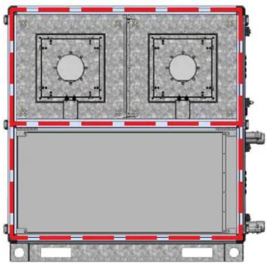
natural_image
Technical diagram of a dual-panel electronic enclosure with mounting holes and wiring (no text or symbols)After gluing the seal, place the blocks as close to each other as possible and connect the blocks using the connecting elements on the end profiles of the unit so that the blocks fit tightly together. Use the supplied M8x25 screws for the connection (24 pieces included in total).

natural_image
3D mechanical assembly diagram showing a bracket with mounting flanges and a lever mechanism (no text or symbols)Each connecting element contains a total of 2 M8 threads for 2 pcs of M8 screws
Each block No. 1 and No. 3 is provided with a total of 6 pieces of connecting elements in each connecting plane. The middle block No. 2 is equipped with a total of 12 pieces of connecting elements.
If the unit is equipped with the ROOFPACK accessory, it is necessary to connect the roof parts of the unit in the connecting planes of the blocks. Is it necessary to use the enclosed rivets ∅ 4 mm and connecting strips to connect the roofs, which are pre-assembled on the individual blocks.

Before connecting the unit to the HVAC piping, check the markings and directions of the air flow in the unit. Marking of air currents ODA / SUP / ETA / EHA - see. chap. 3.2.
Always follow the markings and directions of airflows that are marked on the stickers on the outer casing of the unit.
The unit must be connected to the piping via flexible sleeves to prevent the transmission of vibrations to the air distribution systems. The flexible sleeves must be bridged by a flexible conductive connection for the discharge of static electricity from the device. If the elastic cuffs are secured with spacers against damage during transport and storage, these can be removed only after the attachment of both flanges, on the one hand to the unit and on the other to the air distribution systems.
The unit is equipped with integrated connection flanges for connection to air ducts. The spacing of corner holes with M8 threads is adapted for P30 flanges (the height of the air flange flange is 30 mm).
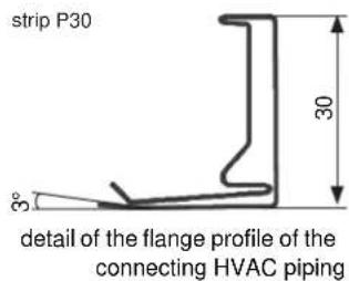

If the unit is equipped with a I&C system from the factory, the individual blocks are already equipped with cabling. Installation boxes and connectors are located in the place of the connecting plane of the blocks. It is necessary to connect all connectors after mechanical connection of blocks according to the marking on the connectors (marking on the MALE connector = marking on the FEMALE connector). Connect loose hoses to the manostats according to the markings at the individual ends of the hoses. In case of using the StartPACK service from S&P UK Ventilation Systems Ltd the final connection of connectors and hoses will be performed by S&P UK Ventilation Systems Ltd.
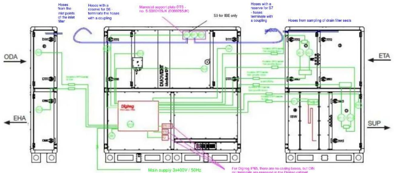
block wiring diagram for DUOVENT® MODULAR DV/RV units with DCA/DCB water heater (for AV2 unit position)

block wiring diagram for DUOVENT® MODULAR DV/RV units with DI electric heater (for AV2 unit position)

natural_image
Interior view of a stainless steel industrial facility with two white cables labeled KL1 and KL2, no visible text or symbols beyond labels.design of connectors on the border of the 1st and 2nd transport block - power supply of ODA and EHA input damper actuators

natural_image
Two electrical control units (V1 and V2) with blue and white connectors, connected by wires and a warning symbol (no readable text or labels beyond component identifiers)design of connectors on the border of the 2nd and 3rd transport block - power supply of fans at inlet, outlet and temperature sensors in block no. 3
5.2.3 ELECTRIC HEATER CONNECTION (MARKED "DI" IN UNIT CODE)
The unit equipped with an electric DI heater is connected to the relevant control system and further to the electrical network. The general safety regulations for the assembly and installation of electrical equipment apply to this equipment. On the front of the unit there is a cover with a release button for the non-automatic thermal fuse. The non-automatic thermal fuse reacts in the event of overheating of the heater's heating block (temperature above +120 °C). The electric heater is also equipped with an operating thermostat with automatic reset (set temperature is +60 °C, when it is exceeded, the operating thermostat opens and switches off the heater, after cooling below +60 °C the heater automatically switches on again).
Location of the release button under the cover on the outer casing of the operating side of the unit:

natural_image
Mechanical assembly diagram showing a lock mechanism with a red arrow indicating motion (no text or symbols)If the electric heater emergency thermostat of the unit trips again, it is necessary to immediately look for the cause of the fault. Repeated manual reset of the heater overheating error by a button on the heater is inadmissible and is not a solution to the fault. The reason for this type of failure may be insufficient air flow through the electric heater of the unit, which will cause the heating rods to overheat and the intervention of the emergency thermostat. The solution is to increase the air flow to the required minimum level according to the following table.
Table of minimum air flows through the electric heater:
| Size unit | Minimum air flow (m3/h) |
| DV/RV 8500 | 5000 |
| DV/RV 10100 | 5500 |
| DV/RV 12000 | 6000 |
| DV/RV 14500 | 6800 |

CAUTION!
Before service works!
- The unit must be disconnected from the power supply
- The fan impellers shall not rotate
• Electric heater bars must be cooled to min. 30 °C
• The unit service switch is locked in OFF position

CAUTION!
It is forbidden to remove, bypass or disconnect safety devices, safety functions and protective devices! Any intervention in the internal connection of the heater is forbidden!

CAUTION!
In case the unit is not fitted with Digireg® control box
from the factory, it is necessary to ensure minimum run-down of inlet fan after stopping of the electric heater to cool the heating bars. Min. run-down time is 4 minutes.

CAUTION!
In case the unit is not fitted with Digireg ^® control box from the factory, it is necessary to ensure blocking of the electric heater power supply by means of a safety contactor, which should be connected in series with the emergency and operation thermostat of the electric heater and with the fan running detection element (such as manostat). In any case may the the electric heater started without running the fan, which provides minimum air flow at the heater!!!
During maintenance, it is necessary to check the tightening of the terminals, clean the space of the heater terminal block from dust and dirt, monitor whether some components show signs of excessive warming, water leakage, mechanical or other damage. Increased attention must be paid to safety circuits, especially the thermal protection of the heater, including the correct response of the control system or power supply switchboard. Faults found must be rectified immediately. These inspections are carried out at least once a year (or more often according to local conditions) by an authorized professional service company.

natural_image
Interior view of an electrical cabinet showing wiring and components (no visible text or symbols)access to the heater connection terminal block -
- after removing the front panel on the operating side of the unit
Example of connection of the two section electric heater terminal block:
PT - operating thermostat with automatic reset
NTP - non-automatic thermal fuse with manual reset


CAUTION!
PT and NTP safety devices must always be connected to the contactor circuit of the electric heater!
5.2.4 WATER HEATER CONNECTION (MARKED "DCA" OR "DCB" IN UNIT CODE)
The unit fitted with the water heater is to be connected to the heating medium by means of the 3-way mixing unit (see "Types of ESU control units"). The water heater outlets are located on the front of the unit and are threaded. When tightening the heat exchanger connections, it is necessary, for example, to hold the heat exchanger neck with a second wrench so that the tightening torque is not transmitted to the heat exchanger body.
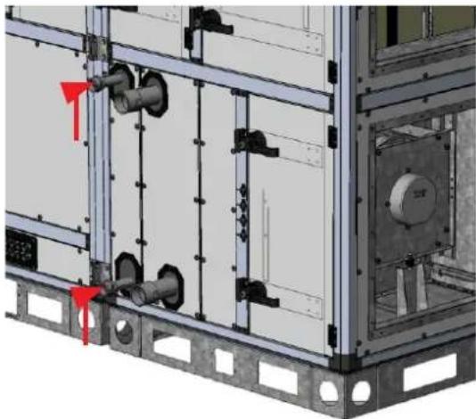
natural_image
3D mechanical assembly diagram showing internal components and mounting brackets (no text or symbols)Table of dimensions of water cooler connection necks:
| Unit size | heater/cooler type | thread |
| DV/RV 8500 | IBW-A DUOVENT® 8500-ErP2018-xV | 1 1/2" |
| IBW-B DUOVENT® 8500-ErP2018-xV | 1 1/2" | |
| DV/RV 10100 | IBW-A DUOVENT® 10100-ErP2018-xV | 1 1/2" |
| IBW-B DUOVENT® 10100-ErP2018-xV | 1 1/2" | |
| DV/RV 12000 | IBW-A DUOVENT® 12000-ErP2018-xV | 2" |
| IBW-B DUOVENT® 12000-ErP2018-xV | 2" | |
| DV/RV 14500 | IBW-A DUOVENT® 14500-ErP2018-xV | 2" |
| IBW-B DUOVENT® 14500-ErP2018-xV | 2" |
For correct connection, the direction of water flow is indicated on the housing of the unit by auxiliary labels. The exchanger must be connected in counter-current to the flow of air passing through (in co-current connection, the exchanger loses approx. 25 % of its output). I.e. that the heating water inlet is always on the far side from the air inlet on the front surface of the exchanger - see. following image.

For the water heater to function properly, it is necessary to bleed the heater after connecting and filling the system with heating water. The vent screws are located directly at the heat exchanger connection sockets and are accessible from the outside of the unit - see. following pictures.

natural_image
3D mechanical assembly diagram showing two connected cylindrical components mounted on a metal frame, with red arrows indicating direction of motion (no text or symbols present)Before starting service work on the heat exchanger (when replacing it), it is necessary to drain the heating water distribution system connected to the heat exchanger and drain the heat exchanger itself using the drain screws on the heat exchanger collectors. The heat exchanger can then be disconnected from the heating water distribution system and removed from the unit.
Max. operating water temperature of water heaters: +110 °C
Max. operating water pressure of water heaters: 1.6 MPa
Hydrogen exponent of heating water: pH 7-9
Heating water hardness: 1.0 mval/l
If necessary, water heaters can be operated with a heating medium based on a solution of water and ethylene glycol or propylene glycol - antifreeze mixture. In this case, it is necessary to count on a reduction in the output of the water heater (eg for a mixture of water and ethylene glycol in a ratio of 1:4, the reduction in heating output is approx. 11% ). In all units with outdoor design we recommend to use the anti-freeze mixture as the heat-transfer medium.
All pipes must be connected independently of the heat exchangers - the heating water pipes must not act on the necks of the heat exchangers due to their weight and expansion. We recommend the antifreeze mixture as a heat transfer medium for all outdoor units.
Units taken out of service must be protected against freezing by draining water from all parts of the unit. Residual water from the exchanger can be expelled with compressed air.
When starting the unit at an outdoor air temperature below +5 °C, the active fluid supply to the heater must be opened before starting the fan, which must have the projected temperature at the heating water supply to the heater. I.e. the boiler circuit must be in operation, the boiler must heat and provide the warm water to the system.

CAUTION!
For water heaters, it is necessary to pay attention to the correct installation and function of the frost protection. Capillary thermostat of the anti-freeze protection must be installed downstream the water heater. Another level of the anti-freeze protection is contact temperature sensor at the heating water return line. Also the units not intended for continuous operation, such as backup units, must be fitted with the antifreeze protection. A year-round supply of heating water must be provided in front of the water heater control valve so that all frost protection functions are active.

CAUTION!
For unit variants with water bivalence and heat pump (marked DXr DCA or DXr DCB in the unit code), it is recommended to use an antifreeze mixture of water and ethylene glycol (eg. FRITERM E Stabil) in min. concentration 1:2 (i.e. 1 part of FRITERM E Stabil: 2 pats of water). If the antifreeze mixture cannot be used, a year-round supply of heating water must be provided in front of the water heater control valve so that all frost protection functions are active. For units that are not equipped with a Digireg® control system, it is recommended to install a capillary antifreeze thermostat behind the water heater in the direction of air flow, which activates the antifreeze protection functions of the water heater in the customer control system of the unit.
5.2.5 WATER COOLER CONNECTION (MARKED „DCC“ IN THE UNIT CODE)
A unit equipped with a water cooler (DCC unit code) is connected to the cooling medium by means of a three-way mixing unit (see "Types of ESUCH control units"). The water cooler outlets are located on the front of the unit and are threaded. When tightening the heat exchanger connections, it is necessary, for example, to hold the heat exchanger neck with a second wrench so that the tightening torque is not transmitted to the heat exchanger body.
Table of dimensions of water cooler connection sockets:
| Size unit | heater type | thread |
| DV/RV 8500 | IKW DUOVENT® 8500-ErP2018-xV | 2" |
| DV/RV 10100 | IKW DUOVENT® 10100-ErP2018-xV | 2 1/2" |
| DV/RV 12000 | IKW DUOVENT® 12000-ErP2018-xV | 3" |
| DV/RV 14500 | IKW DUOVENT® 14500-ErP2018-xV | 3" |
For correct connection, the direction of water flow is indicated on the housing of the unit by auxiliary labels. The exchanger must be connected in counter-current to the flow of air passing through (in co-current connection, the exchanger loses approx. 25 % of its output). I.e. that the cooling water inlet is always on the far side from the air inlet on the front surface of the exchanger - see. following image.
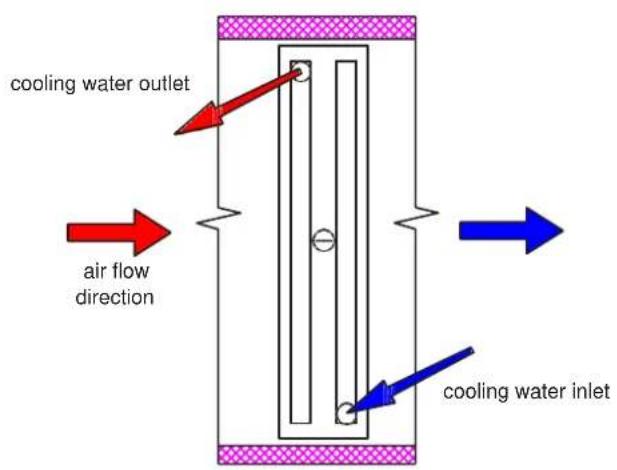

For the water cooler to function properly, the cooler must be vented after connecting and filling the system with cooling water. The vent screws are located directly at the heat exchanger connection necks. The vent screws are accessible from the outside of the unit - see. previous chapter.
Before starting service work on the heat exchanger (when replacing it), it is necessary to drain the heating water distribution system connected to the heat exchanger and drain the heat exchanger itself using the drain screws on the heat exchanger collectors. The heat exchanger can then be disconnected from the cooling water distribution system and removed from the unit.
Max. operating water pressure of water coolers: 1.6 MPa
Hydrogen exponent of heating water: pH 7-9
Heating water hardness: 1.0 mval/l
The water cooler section is equipped with a drip eliminator, which must always be installed in the unit during cooler operation. When installing the drip eliminator, it is necessary to pay attention to the correct direction of the eliminator lamellas with respect to the flowing air - see. following image.

All piping must be installed independently of the heat exchangers - the cooling water piping must not act on the necks of the heat exchangers due to its weight and expansion. We recommend the antifreeze mixture as a heat transfer medium for all outdoor units.
Units taken out of service must be protected against freezing by draining water from all parts of the unit. Residual water from the exchanger can be expelled with compressed air.

INFORMATION
DCA/DCB/DCC water exchanger can be used also for water with antifreeze mixture (based on propylene-glycol, ethylene-glycol etc.). We recommend e.g. concentrated antifreeze liquid FRITERM E STABIL or FRITERM P PLUS (for temperature resistance to -18 °C the recommended dilution is 1:2 = 1 part of FRITERM E STABIL : 2 pats of water). The recommended dilution for each type of coolant and the required frost resistance is included in the packaging of these antifreeze concentrates. For DCA/DCB/DCC water exchangers we always recommend filling with antifreeze mixture with min. concentration of 20:80 as the liquids contain also other corrosion inhibitors and at least minimum resistance of the mixture to the frost of ca -5 °C. It is necessary to count on a reduction in the output of the water heater (eg for a mixture of water and ethylene glycol in a ratio of 1:4, the reduction in heating output is approx. 11 %).
5.2.6 DIRECT EVAPORATOR CONNECTION (MARKED "DX" OR "DXR" IN UNIT CODE)
The unit equipped with a direct evaporator is connected via a Cu pipe to the appropriate condensing unit or heat pump (the method and design of the connection is not the subject of these installation instructions). The direct cooler outlets are located outside the unit. The evaporator is filled with dry air or nitrogen at the factory. After removing the valves on the evaporator necks, work on the refrigerant circuit assembly must begin immediately. The connection of the refrigerant circuit for direct cooling must be carried out by a specialist company. It is mandatory to perform a "Refrigerant leak test" on the refrigerant circuit. This test is performed only by a technician with the appropriate authorization (according to the law).

natural_image
Two cylindrical mechanical components mounted on a black circular base, with no visible text or symbols.example of the design of the connection sockets of one direct evaporator circuit
5.2.7 CONDENSATE DRAIN CONNECTION
To ensure the drainage of condensate from the interior of the unit, the drain spout must be connected to the sewer system via a siphon with an odour trap. The siphon must be located next to the unit. The condensate drain is as standard located on the exhaust part of the degraded air under the recuperative air exchanger and under the condenser or evaporator.

location of drain necks on DUOVENT® MODULAR DV units
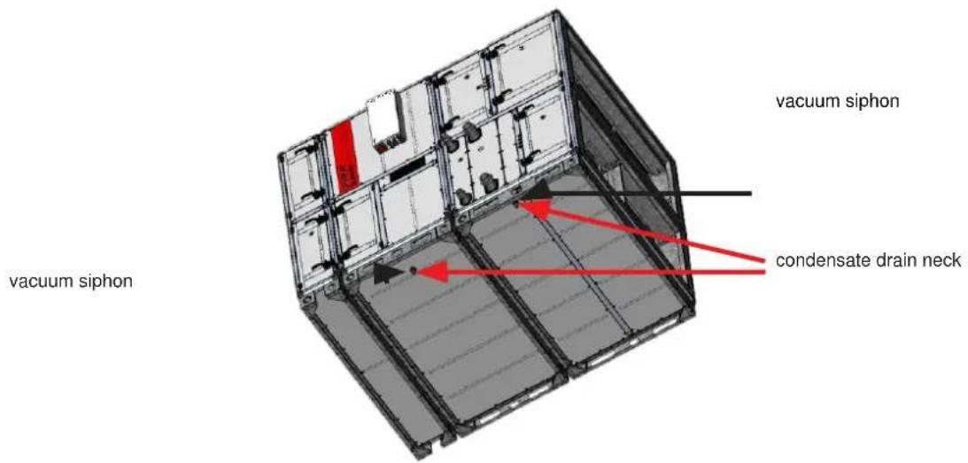
location of drain necks on DUOVENT® MODULAR RV units
For outdoor units, the unit's siphon must be equipped with a suitable heating cable and external insulation to prevent condensate from freezing in the siphon and the entire condensate route. The heating cable is not part of the delivery of S&P UK Ventilation Systems Ltd.
Scheme of overpressure siphon (type SF-P 400 PR):
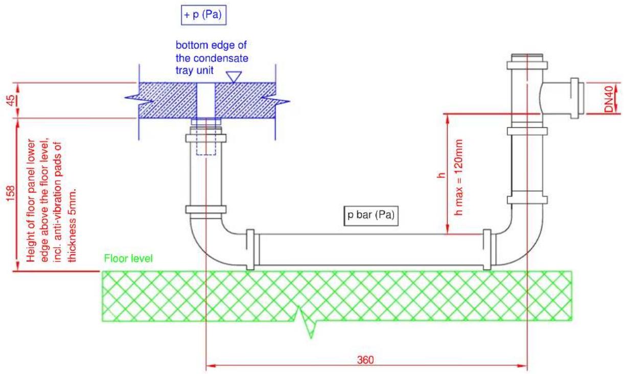
Scheme of vacuum siphon (type SF-P 300):

Siphon working height:
$$ h = 1 0 + (\Delta p / 1 0) \dots (m m) $$
Δp ... absolute value of vacuum or overpressure at a given location of the unit

CAUTION!
Insufficient siphon working height causes collection
of the condensate in condensate tray of the unit.
Then the condensate flows out of the unit!!!
Vacuum siphon (SF-P 300) - contains a ball that serves as a non-return valve for the correct function of the siphon not flooded with water and prevents the penetration of odours into the unit. The siphon must be fitted to the unit gas-tightly via the enclosed rubber sleeve. Max. usable vacuum 1100 Pa.
Overpressure siphon (SF-P 400 PR) - the siphon must be completely filled with water to prevent the penetration of odors from the sewer into the interior of the unit when it is shut down. If the overpressure siphon is sufficient, it can be determined by visual inspection. When the device is running and started, the water must not be forced into the drain pipe after the siphon has been filled. Max. usable overpressure 1100 Pa.
Siphons are used individually for each condensate drain on the unit. The condensate drain behind the individual siphons of one unit assembly can be connected to one pipe. The drainage nozzles of the unit must not be connected by piping and then into one siphon. In winter, the outdoor units must be tempered by a condensate route, including anti-freeze siphons, e.g. electric heating cables. After mounting, the siphon must be fixed so that it does not disengage spontaneously due to the weight of the water inside.
5.2.8 BYPASS AND MIXING FLAP OF MODULAR DV UNITS
In the basic version, each unit is equipped with a bypass valve of the plate heat exchanger (BP). The bypass is used for summer ventilation, defrost control of the recuperation exchanger in the event of a threat of icing and to regulate the efficiency of the recuperation exchanger. In conjunction with a mixing flap or circulation flap (marked MX or C in the unit code), fresh air is mixed with the required amount of exhaust air in the bypass area. The mixing flap allows you to efficiently mix part of the exhaust air with fresh air or allows the unit to have a 100 % recirculated air circulation mode. This mode is mainly used for preheating or pre-cooling to the desired temperature. Inlet and outlet fans are in operation in the circulation and mixing mode.
Location of mixing (MX/C) and bypass damper (BP) for DUOVENT® MODULAR DV units:
ODA flap
BP bypass flap
mixing flap (MX or C)
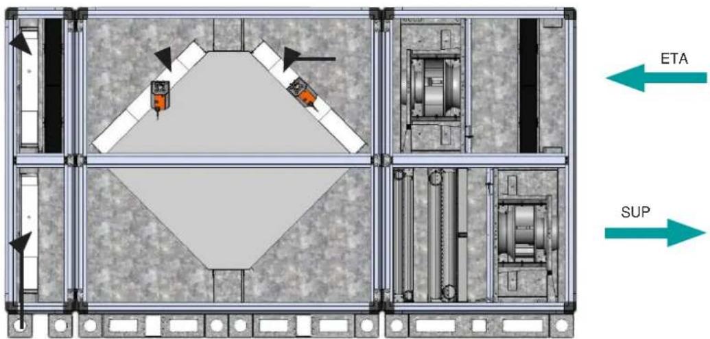
EHA flap
Mixing mode (MX) - ODA + EHA damper open to 100 %, MX damper open according to the required amount of mixing air.
Circulation mode (C) - damper ODA + EHA completely closed, damper C open to 100 %.
Control torques and types of bypass and mixing flap actuators:
| Unit type | flap type | min. control torque [Nm] | possible types of BELIMO actuators |
| DUOVENT® MODULAR DV 8500 | BP | 20 | SM24 A-SR |
| DUOVENT® MODULAR DV 10100/12000/14500 | BP | 40 | GM24 A-SR |
| DUOVENT® MODULAR DV 8500/10100/12000/14500 | MX/C | 10 | NM24 A-SR |
5.2.9 MIXING FLAP OF DUOVENT® MODULAR RV
DUOVENT®MODULAR RV units are not fitted with the regeneration exchanger bypass, but can be fitted with circulation or mixing flap (marked as MX or C in the unit code). The mixing flap allows you to efficiently mix part of the exhaust air with fresh air or allows the unit to have a 100 % recirculated air circulation mode. This mode serves particularly for pre-heating or pre-cooling to the required temperature. Inlet and outlet fans are in operation in the circulation and mixing mode.
Location of the mixing (MX/C) flap for DUOVENT® MODULAR RV:
EHA flap
ODA flap
mixing flap (MX or C)

Mixing mode (MX) - ODA + EHA damper open to 100 %, MX damper open according to the required amount of mixing air.
Circulation mode (C) - damper ODA + EHA completely closed, damper C open to 100 %.
Control torques and types of bypass and mixing flap actuators:
| Unit type | flap type | min. control torque [Nm] | possible types of BELIMO actuators |
| DUOVENT® MODULAR RV 8500/10100/12000/14500 | MX/C | 10 | NM24 A-SR |
5.2.10 INLET AND OUTLET FLAP OF DUOVENT MODULAR DV/RV
In basic version the unit is fitted with inlet flap for fresh and waste air (ODA and EHA). The arrangement of the flaps in the unit is shown on the picture above.
When using a variant of the unit with a water heater DCA or DCB, it is recommended to mount an actuator with an emergency function on the fresh air inlet flap.
Control torques and types of inlet damper actuators
| Unit type | min. control torque [Nm] | possible types of BELIMO actuators | possible types of BELIMO actuators with emergency function |
| DUOVENT® MODULAR DV/RV 8500 | 10 | NM24 A | NF24 A |
| DUOVENT® MODULAR DV/RV 10100/12000/14500 | 20 | SM24 A | SF24 A |
5.2.11 BASIC ACCESSORIES OF DUOVENT® MODULAR DV/RV UNITS
5.2.11.1 CONDENSATE DRAIN SIPHONS
Condensate siphons must be ordered as a separate item, they are not included in the delivery of the unit. Detailed description of siphon types - see. chap. 5.2.7.
5.2.11.2 ESU WATER HEATER OR ESUCH WATER COOLER CONTROL UNIT
The ESU or ESUCH node must be ordered as a separate item, it is not part of the delivery of the unit.

natural_image
Industrial piping and valve assembly with brass fittings and orange control box (no visible text or symbols)
CAUTION!
The design of a suitable mixing unit must be individually adapted to the conditions of the application in order to ensure sufficient valve authority!
The mixing control unit is used to control the flow or temperature of heating (cooling) water to the water heaters/coolers. The ESU node regulates the heating water inlet temperature to the water heater by mixing the inlet water and return, the ESUCH node regulates the flow of cooling water to the water cooler at a constant cooling water inlet temperature (designation in the type symbol indicates pump type and Kv value of mixing valve). The control is provided by a BELIMO servomotor. For control nodes in cooperation with Digireg® control, it is necessary to use version B, which features a three-point actuator, designed for control by a Digireg® controller. Version A can be controlled by a 0...10 V signal. In addition to power control, the control system also protects the water heater against freezing with the help of an ESU node. The water flowing through the unit may not contain impurities, solid admixtures and aggressive chemicals that damage copper, brass, stainless steel, zinc, plastics, rubber. The highest permitted operating parameters of the heating water are as follows:
• Maximum water temperature +110 °C
• Maximum water pressure 1 MPa
• Minimum water pressure 20 kPa
The water temperature must not fall below the ambient air temperature during operation, as there is a risk of condensation in the pump motor. The minimum operating water pressure ensures that no air is sucked in by the vent valve, which must be mounted at the highest point of the water circuit.
ESU unit component arrangement diagram:

flowchart
graph TD
    A["Hot-water exchanger"] --> B["Spring"]
    B --> C["Valve"]
    C --> D["Pressure Control Valve"]
    D --> E["Return Line"]
    style A fill:#f9f,stroke:#333
    style B fill:#ccf,stroke:#333
    style C fill:#cfc,stroke:#333
    style D fill:#fcc,stroke:#333
    style E fill:#ffc,stroke:#333
ESUCH unit component arrangement diagram:
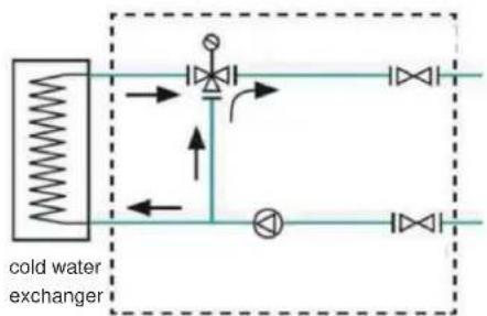
flowchart
graph TD
    A["cold water exchanger"] --> B["Valve"]
    B --> C["Control Valve"]
    C --> D["Valve"]
    D --> E["Control Valve"]
    E --> F["Valve"]
    F --> G["Control Valve"]
    G --> H["Valve"]
    H --> I["Control Valve"]
    I --> J["Valve"]
    J --> K["Control Valve"]
    K --> L["Valve"]
    L --> M["Control Valve"]
    M --> N["Valve"]
    N --> O["Control Valve"]
    O --> P["Valve"]
    P --> Q["Control Valve"]
    Q --> R["Valve"]
    R --> S["Control Valve"]
    S --> T["Valve"]
    T --> U["Control Valve"]
    U --> V["Valve"]
    V --> W["Control Valve"]
    W --> X["Valve"]
    X --> Y["Control Valve"]
    Y --> Z["Valve"]
The mixing unit is connected to the heater or cooler. The mixing unit must never be loaded by tension and twisting of the connected piping. Mixing units should be mounted on separate hinges using heating sleeves on the wall, pipes or on an auxiliary structure. When placed under the ceiling, it is necessary to maintain control and service access to the mixing unit for easy cable connection and service access. The filter requires regular inspection, maintenance and cleaning. When assembling the node, it is necessary to turn the filter downwards with the sludge pan. If the position is incorrect, there is a risk of increased clogging/choking of the filter. Reduced throughput or even blockage of the filter results in a significant decrease in heater power and increases the risk of frost heater. Especially during the test operation, it is necessary to check and clean the sludge pan. If the filter is often clogged, the entire heating circuit must be cleaned. Even during normal operation of the device, it is necessary to check the filter regularly. When cleaning the filter, all water lines must be closed to minimize water leakage from the system. Install the mixing unit to enable escape of the air to the heater or boiler circuit vent points. The mixing node must be fixed so that the pump motor shaft is in a horizontal position. After flooding the system, the circulation pump must be bled according to the manufacturer's instructions (Grundfos). During connection of the mixing node is is necessary to check correct setting of the valve and actuator. With an assembled mixing unit, the position of the inner segment of the mixer can be identified by the shoulder on the front of the shaft extension. The perpendicular line to the mounting surface at the three-way valve points to the axis of the inner segment. For the version with a three-way valve, proceed as follows. Of the three paths, the valve always has the path to which the bevelled surface on the valve shaft points. With an assembled mixing unit, the setting can be identified by the notch on the face of the shaft extension. The notch always points to a closed water line - see following image.

6. ELECTRICAL INSTALLATION
In general, it is necessary to observe the provisions of ČSN 12 2002 and other related regulations. The device must be disconnected from the mains during any inspection or service activities. The connection and earthing of electrical equipment must comply in particular with ČSN 33 2000-5-51 ed.3, ČSN 33 2000-5-54 ed.3 and the ČUBP and ČBU decrees on professional competence in electrical engineering no. 50.
The connection of the DUOVENT ^® MODULAR DV/RV unit equipped with the Digireg ^® I&C control system to the electrical distribution network is made by a separate supply cable, which is not part of the delivery of the device.
6.1 ELECTRIC HEATER CONNECTION
The cables of the electric heater are led to the terminal board of the electric heater and properly marked for the subsequent connection of the control and management system. Additional information of the electric heater connection see chap. 5.2.3.
6.2 INSTRUMENTATION AND CONTROL (I&C) SYSTEM
The standard part of the unit is its own control system. The design of the unit is ready for cooperation with the Digireg ^® digital control unit.
6.2.1 DIGIREG® DIGITAL CONTROL SYSTEM
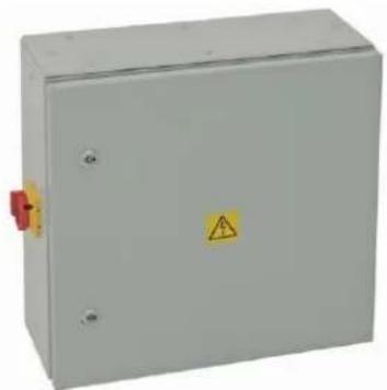
The control system is located in a compact sheet steel switchboard equipped with a main switch, digital controller on the PCB board and safety and switching elements for individual HVAC units. The cables pass through plastic bushings with locking in the left side of the cabinet.
Basic dimensions of Digireg® M3-Vx switchboard with protection level IP20:

natural_image
3D rendering of a rectangular electronic component with labeled dimensions (640, 120, 280) and internal features (no text or symbols beyond measurement labels)The switchboard M3-E36 with protection level IP20 features dimensions of 660 x 280 x 120 mm.
natural_image
Exterior view of a gray electrical control box with warning symbol (no text or labels visible)The switchboard Digireg ^® (M3-Vx and M3-E36 / E72) with protection level IP65 features dimensions of 600 x 600 x 210 mm.
6.3.2 TEMPERATURE REGULATION
The Digireg® controller is designed to control the output of the heater or cooler of the air handling unit to reach the desired temperature. Digireg® can command direct cooling or a heat pump. There is a 3-point output for servo drive of the mixing valve, direct power outputs SSR for electric heating or two analogue outputs 0–10 V / 0–20 mA. The heat pump or cooling unit is controlled by potential-free contacts.
- Regulation to a constant supply air temperature
It uses one temperature sensor in the supply pipe, the supply air is heated or cooled to the required set temperature within the minimum and maximum configured temperature.
- Regulation to a constant temperature of the exhaust air
It uses one temperature sensor in the supply pipe, the supply air is heated or cooled to the required set temperature within the minimum and maximum configured temperature.
- Spatial temperature control (for constant room temperature)
Cascade control is used with limitation of the minimum and maximum supply air temperature. The main sensor is placed in a ventilated area, the supply air sensor is placed in the outlet of the unit in a place with sufficient air mixing. If the room temperature is higher than the set value, the controller will try to reduce the supply air temperature to the set minimum supply air temperature. If the room temperature falls below the set value, the controller tries to compensate for this by increasing the supply air temperature. The room temperature can be selected as the room temperature, the temperature from the sensor in the controller, or from a separate sensor connected to the motherboard. The controller cools or heats according to the set parameters in the automatic summer/winter mode according to the outdoor temperature and time dependencies. Manual mode selection is also possible. The heater can be hot water type, controlled by a three-point actuator, or electric type, directly controlled by SSR, or external TRIAC switches 0-10 V. Electric heater controlled by internal SSR can have up to 72 kW depending on the cabinet, water heater is not limited (its power is determined by the mixing unit size). Cooling can be cold water type, controlled by a 0-10 V analogue actuator or direct type in conjunction with a condensing cooling unit.

CAUTION!
For units with a direct evaporator (marked DX and DXr in the unit code), it is possible to maintain the required air temperature in the room with accuracy, depending on the correctness of the project and the correct function and setting of the ventilation system with accuracy of ±2 ^ .
6.3.3 INSTALLATION
IP20 protection controllers are designed for installation in an indoor dry environment without aggressive chemicals in normal areas according to ČSN 33 2000-3, ambient temperature up to 30 °C. The short-circuit resistance of the Digireg ^ switchboard is 6 kA. The distribution board protection level is IP20 or IP65 and the material is specified below in the catalogue lists on www.solerplau.co.uk.

CAUTION!
Digireg ^® distribution boards are not designed for direct installation to the flammable material!

CAUTION!
For recuperation units delivered with free standing Digireg ^® control box, which is not fixed to the unit wall, it is necessary to provide firm housing of the cable harness between the unit and control box in the firm cable line (such as cable trays, cable bench etc.). The cable harness between the unit and the control box shall not be freely suspended or positioned on the floor!!! On laying of the harness it is possible to start the works on connection of individual wires to the Digireg ^® control box.
Cross-sections of power cables (fans, pumps, electric heaters...) must be designed according to specific installation conditions in accordance with ČSN 33 2000-5-52 ed.2.
The installation must be carried out by an authorized person working on electrical equipment in accordance with legal requirements and familiar with the function of the individual components of air conditioning and control. Observe the valid ČSN during installation. An initial inspection must be performed before commissioning. For the assembly and installation of air conditioning, an authorized project of air conditioning and M&R is required, which solves both the air outputs and the piping system, as well as the electrical connection of elements and operating modes.
The actual commissioning and setting of the basic parameters of the controller must be performed by an authorized company with authorization and training from S&P UK Ventilation Systems Ltd.
The cables must be secured outside the unit against being pulled out in the installed bushings.
The cable routes of safe and mains voltage must be separated due to electromagnetic compatibility requirements. It is necessary to build 2 cable routes at a distance of at least 20–30 cm from each other, if possible with a minimum of crossing. A grounded metal partition in the entire height of the metal grounded gutter is also permissible
If the main supply has a conductor cross-section of less than 6 mm^2 , we recommend connecting the controller to the earthing system with a copper conductor with a cross-section of at least 6 mm^2 due to the impedance of the earth conductor for high-frequency interference. We recommend to fit the power supply with surge protectors.
It is necessary to check the function of all connected elements, especially emergency inputs, the direction of rotation of the fans, the correct phasing of the damper actuators and mixing valves. If the unit is equipped with Digireg® control system directly from the factory, a SETPACK test package has been performed on the unit. SETPACK covers basic settings of control system parameters and testing of all peripherals.
6.3.4 TECHNOLOGY SCHEME OF DIGIREG® I&C SYSTEMS
Legend to the diagrams:
S1 room temperature sensor
S2 supply air temperature sensor
S3 temperature sensor for frost protection of water heating
S4 temperature sensor for exhaust air
S5 exhaust air temperature sensor
S6 pressure sensor on the supply filter
S7 drain filter pressure sensor (optional)
S8 thermostat as protection against freezing of the direct evaporator
S9 supply fan pressure sensor (mandatory - monitors fan operation)
S10 intake air temperature sensor
S11 recuperator icing sensor
S13 outdoor temperature sensor (enable condenser unit operation)
V1 supply fan
V2 exhaust fan
KL1 inlet flap actuator (circulation)
KL2 outlet flap actuator (can be coupled with KL1)
KL3 recuperator bypass actuator
KL4 mixing actuator for integrated flaps
ST1 heating water mixing valve actuator
ST2 cooling water mixing valve actuator
KJ condensing unit
PR control of the rotation exchanger drive

flowchart
graph TD
    A["House"] --> B["Switch K1.2"]
    B --> C["Switch S7"]
    C --> D["Switch S4"]
    D --> E["Drain"]
    E --> F["Switch S6"]
    F --> G["Switch P1"]
    G --> H["Switch S20"]
    H --> I["Switch S13"]
    I --> J["Plate Exchanger"]
    E --> K["Switch V1"]
    K --> L["Switch V2"]
    L --> M["Switch V5"]
    M --> N["Switch S5"]
    N --> O["Switch S1"]
    style E fill:#f9f,stroke:#333
    style F fill:#bbf,stroke:#333
    style G fill:#bbf,stroke:#333
    style H fill:#bbf,stroke:#333
    style I fill:#bbf,stroke:#333
    style J fill:#dfd,stroke:#333
    style K fill:#dfd,stroke:#333
    style L fill:#dfd,stroke:#333
    style M fill:#dfd,stroke:#333
    style N fill:#dfd,stroke:#333
    style O fill:#dfd,stroke:#333
    subgraph "plate exchanger"
        direction TB
        E -->|Red dashed arrow| F
        F -->|Blue solid line| G
        G -->|Blue solid line| H
        H -->|Blue solid line| I
        I -->|Blue solid line| J
        J -->|Blue solid line| K
        K -->|Blue solid line| L
        L -->|Blue solid line| M
        M -->|Blue solid line| N
        N -->|Blue solid line| O
        O -->|Blue solid line| P
        P -->|Blue solid line| Q
        Q -->|Blue solid line| R
        R -->|Blue solid line| S
        S -->|Blue solid line| T
        T -->|Blue solid line| U
        U -->|Blue solid line| V
        V -->|Blue solid line| W
        W -->|Blue solid line| X
        X -->|Blue solid line| Y
        Y -->|Blue solid line| Z
        Z -->|Blue solid line| AA
        AA -->|Blue solid line| AB
        AB -->|Blue solid line| AC
        AC -->|Blue solid line| AD
        AD -->|Blue solid line| AE
        AE -->|Blue solid line| AF
        AF -->|Blue solid line| AG
        AG -->|Blue solid line| AH
        AH -->|Blue solid line| AI
        AI -->|Blue solid line| AJ
        AJ -->|Blue solid line| AK
        AK -->|Blue solid line| AL
        AL -->|Blue solid line| AM
        AM -->|Blue solid line| AN
        AN -->|Blue solid line| AO
        AO -->|Blue solid line| AP
        AP -->|Blue solid line| AQ
        AQ -->|Blue solid line| AR
        AR -->|Blue solid line| AS
        AS -->|Blue solid line| AT
        AT -->|Blue solid line| AU
        AU -->|Blue solid line| AV
        AV -->|Blue solid line| AW
        AW -->|Blue solid line| AX
        AX -->|Blue solid line| AY
        AY -->|Blue solid line| AZ
        AZ -->|Blue solid line| BA
        BA -->|Blue solid line| BB
        BB -->|Blue solid line| BC
        BC -->|Blue solid line| BD
        BD -->|Blue solid line| BE
        BE -->|Blue solid line| BF
        BF -->|Blue solid line| BG
        BG -->|Blue solid line| BH
        BH -->|Blue solid line| BI
        BI -->|Blue solid line| BJ
        BJ -->|Blue solid line| BK
        BK -->|Blue solid line| BL
        BL -->|Blue solid line| BM
        BM -->|Blue solid line| BN
        BN -->|Blue solid line| BO
        BO -->|Blue solid line| BP
        BP -->|Blue solid line| BQ
        BQ -->|Blue solid line| BR
        BR -->|Blue solid line| BS
        BS -->|Blue solid line| BT
        BT -->|Blue solid line| BU
        BU -->|Blue solid line| BV
        BV -->|Blue solid line| BW
        BW -->|Blue solid line| BX
        BX -->|Blue solid line| BY
        BY -->|Blue solid line| BZ
        BZ -->|Blue solid line| CA
        CA -->|Blue solid line| CB
        CB -->|Blue solid line| CC
        CC -->|Blue solid line| CD
        CD -->|Blue solid line| CE
        CE -->|Blue solid line| CF
        CF -->|Blue solid line| CG
        CG -->|Blue solid line| CH
        CH -->|Blue solid line| CI
        CI -->|Blue solid line| CJ

flowchart
graph TD
    S13["Switch S13"] --> S16["Switch S16"]
    S16 --> F1["F1"]
    F1 --> S11["Switch S11"]
    S11 --> V1["V1"]
    V1 --> S2["S2"]
    S2 --> S1["S1"]
    S5["Switch S5"] --> V2["V2"]
    V2 --> PR["PR"]
    PR --> S7["S7"]
    S7 --> F2["F2"]
    F2 --> S4["S4"]
    S4 --> KL2["KL2"]
    KL2 --> S4
    style S13 fill:#f9f,stroke:#333
    style S16 fill:#ccf,stroke:#333
    style F1 fill:#cfc,stroke:#333
    style V1 fill:#fcc,stroke:#333
    style S2 fill:#cff,stroke:#333
    style S7 fill:#ffc,stroke:#333
    style F2 fill:#cfc,stroke:#333
    style S4 fill:#fcc,stroke:#333
    style KL2 fill:#ffc,stroke:#333
    style PR fill:#fcc,stroke:#333
    subgraph D
        direction TB
        S11 -.-> S10
        S10 -.-> S6
        S6 -.-> F1
        F1 -.-> V1
        V1 -.-> S2
        S2 -.-> S1
    end
    note right of D: 'rotating gexchang'

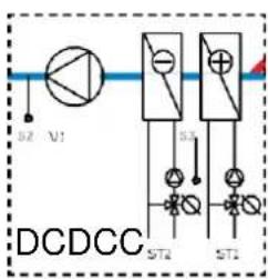
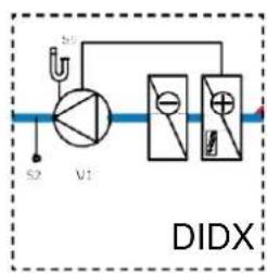


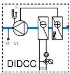
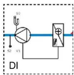

flowchart
graph TD
    A["S2"] --> B["V1"]
    B --> C["K1"]
    C --> D["D"]
HVAC function variants
6.3.5 CONTROL
The controller is operated exclusively via the touch control. Service settings are performed by the appropriate service program, which is only available to trained and certified companies.
Touch control CP for Digireg®:

7. COMMISSIONING
The device may only be put into operation for the first time by a suitably qualified specialist.
7.1 INSTALLATION AND CONNECTION CHECK
Before the first commissioning, it is necessary to check:
• Equipment cleanness, installation completeness/quality
- Fan free rotation
• Operating voltage of installed control system
- Operating voltage of electric motor acc. to type plate
• Actuator control and operating voltage
• Function of condensate drain and trap water flooding
• Cleanness of filter cartridges
- Flap movability
• Tight connection to distribution lines
• Closing of all doors and service holes
Any faults must be rectified before starting the unit for the first time.
7.2 TRIAL OPERATION
The material content of the comprehensive testing includes the commissioning of the device for a pre-agreed time and its continuous inspection. In order to comply with the required air parameters depending on the operation of the building and the technology, it is necessary to fine-tune the device during the test operation, or during the warranty tests.
For the first start of the air handling unit, the company S&P UK Ventilation Systems Ltd offers the STARTPACK assistance service package. Find out about the conditions and scope of the STARTPACK package at www.solerplau.co.uk.
The company putting the unit into operation is obliged to demonstrably train the user's staff. Without proof of operator training, the warranty will not take effect and the device must not be operated.
These instructions serve as an aid for professionals, operators of air handling units, or investors who are assumed to already have experience with the operation of air conditioning systems. The instructions are especially important for the start-up period of the entire system, when more detailed operating regulations are not available. The purpose of these instructions is to allow temporary operation of air handling units and to prevent possible operator errors. Final operating regulations must be prepared in accordance with the operating regulations of the entire building.
8.1 SAFETY INSTRUCTIONS FOR OPERATION AND MAINTENANCE
Follow all safety recommendations to prevent damage to the fans or personal injury. The technical characteristics of this manual must not be changed. The motors of the unit must not be changed. The unit can be connected to a three-phase AC mains supply 400 V/50 Hz. For installation in accordance with EC regulations, the units may only be connected to the mains in accordance with the applicable regulations. The device must be installed in such a way that, under normal operating conditions, it cannot come into contact with any moving or live part. DUOVENT® MODULAR DV/RV units comply with the applicable regulations for electrical equipment. Before carrying out any work on the device, always disconnect the device from the power supply. Always use the appropriate tools. Use the device only for its intended purpose.
8.2 EQUIPMENT SERVICE
To maintain the efficiency of DUOVENT® MODULAR DV/RV 8500 – 14500 units, regular maintenance is required.

CAUTION!
- The unit must be disconnected from the power supply. The unit service switch is locked in OFF
position.
• The fan impellers shall not rotate!
• Electric heater bars must be cooled to min. 30 °C!
8.2.1 FILTER REPLACEMENT AND MAINTENANCE
The filter replacement interval can vary considerably depending on the operating conditions and where the unit is located (the level of outdoor pollution depends on the location near industrial areas, roads or highways, forests or agricultural areas). The filter change interval ranges generally from 6 to 12 months. After unlocking the locks, open the relevant door of the unit. Pull together to remove and then replace all filters on the unit.
Plate filter dimensions:
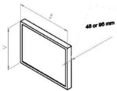
Table of dimensions of filter inserts for DUOVENT® MODULAR DV/RV units
| Size unit | H (mm) | W [mm] | no. of filters in filtration wall |
| 8500 | 341 | 377 | 8 pcs inlet/8 pcs outlet |
| 10100 | 381 | 417 | 8 pcs inlet/8 pcs outlet |
| 12000 | 420 | 456 | 8 pcs inlet/8 pcs outlet |
| 14500 | 459 | 495 | 8 pcs inlet/8 pcs outlet |
Replacement filter inserts can be ordered directly from the manufacturer S&P UK Ventilation Systems Ltd.
Filter replacement procedure - slide the filter out of the rails after opening the door:
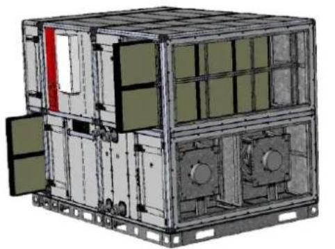
natural_image
3D technical illustration of a modular industrial or military equipment unit with internal compartments and structural beams (no text or symbols visible)DUOVENT® MODULAR RV
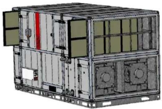
natural_image
3D technical illustration of a modular industrial or logistics container with internal compartments and mounting brackets (no visible text or symbols)DUOVENT® MODULAR DV
To remove the filters from the interior of the unit, it is possible to use a tool that is stored inside the unit at the filter frame. The device can be manipulated with the filter insert by hooking behind the plastic frame of the filter.
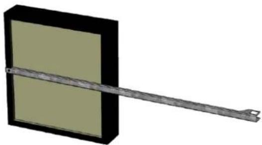
natural_image
3D rendering of a mechanical component with a rectangular frame and a diagonal bar extending from its center (no text or symbols)8.2.2 FAN REPLACEMENT AND MAINTENANCE
The fans are protected by filters and can therefore only be slightly soiled. Nevertheless, it is recommended to perform a visual inspection every 5 years. Remove dust from the impeller with a dry (not wire!) Brush or by blowing with compressed air. Check the condition of the bearings of electric motor (estimated bearing life is 40000 h). If the entire unit or fan needs to be replaced, open the unit door. The fan is located on rubber silent blocks. Loosen the 4 nuts on the vertical partition and the 2 nuts on the silent blocks under the fan motor, lift and remove the fan, including the motor and frame. To access the secondary fan, it is necessary to remove the service wall inside the unit. Keep in mind that the fan must be dynamically and statically balanced again after removing the electric motor.

DUOVENT® MODULAR DV - position AV2

service door
of the unit
removable service wall inside the unit, fastened with M6 screws
access to the second parallel-arranged fan after disassembly of the first fan and removal of the dividing wall (shown inlet part of the MODULAR unit, in the outlet part of the unit the arrangement of the fans is identical)
M8 nut (4 pcs.) of silent-block on vertical dividing wall
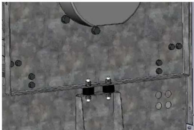
natural_image
Mechanical assembly diagram showing a rotating component mounted on a base with bolt holes and a curved top component (no text or symbols)M8 nut (2 pcs.) of silent-block under fan motor
8.2.3 MAINTENANCE OF RECOVERY PLATE EXCHANGER
The heat recuperation exchanger is protected by filters and can therefore only be contaminated very lightly. Nevertheless, it is recommended to perform a visual inspection every 5 years. If necessary, open the front door of the unit. Remove dust from the boards with a dry brush (not wire!) Or by blowing with compressed air.
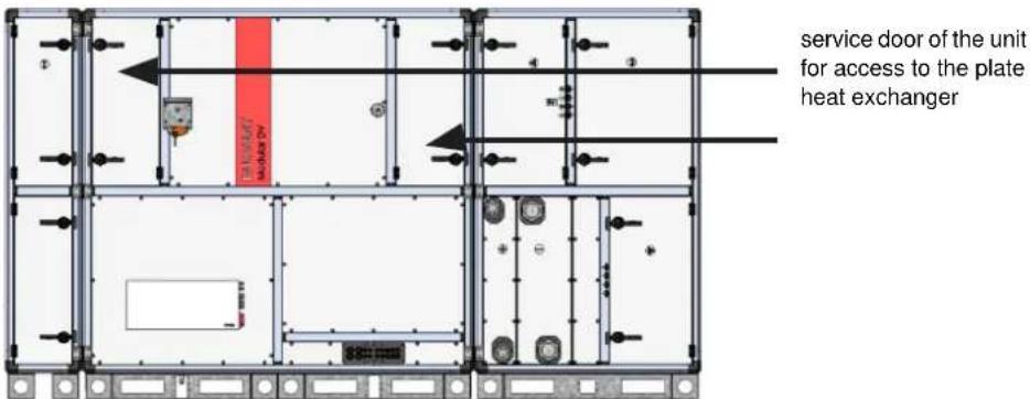
8.2.4 MAINTENANCE OF THE REGENERATION ROTATION EXCHANGER
The heat recovery exchanger is protected by filters and can therefore only be contaminated very lightly. Nevertheless, it is recommended to perform a visual inspection every time the filters in the unit are replaced. It is forbidden to start or operate the rotary heat exchanger with the inspection opening (door) open or the panels exposed. Before starting maintenance and service work on the rotary heat exchanger, the power supply must be switched off and measures must be taken to prevent the regenerator electric motor from being switched on during service work. To access the heat exchanger, open the service door on the operating side of the unit.

service door of the unit for access to the rotary heat exchanger drive
As part of maintenance, it is necessary to check the tension of the drive belt, the condition of the rotor circumferential seal, the condition of the rotor clogging. The rotor is cleaned with compressed air, steam or pressurized water. Cleaning must be performed by trained personnel. Improper cleaning can seriously damage the rotor of the rotary heat exchanger. If it is necessary to slide the rotor out of the unit block, it is necessary to perform the following actions:
- Open the unit door and disconnect the rotor electric motor.
- Remove the complete service side of the unit block, including the partitions and the Digireg® box.
- Loosen and slide the side rails of the heat exchanger stop rotor.
side stop bar of the rotary heat exchanger

natural_image
3D technical illustration of a multi-level industrial or mechanical unit with internal components and mounting brackets (no text or symbols)side stop bar of the rotary heat exchanger
- Slide the rotary exchanger out of the unit block.
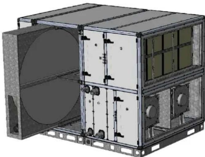
natural_image
3D technical illustration of a mechanical or industrial device with internal components and mounting brackets (no visible text or symbols)The rotary exchanger is driven by an electric motor with an output of 180 W. The electric motor is powered by a frequency converter type VFVN020-1L-2 (370 W, In = 2.4 A, power supply 1x230 V/50 Hz, output 3x230 V/50 Hz), which is located inside the unit on the waste side of the ETA.
8.2.5 SERVICE SWITCH
The service switch is not part of the unit delivered without the I&C system. In case of delivery of the unit including the Digireg® system, the service switch is a part of the control box - see. picture.
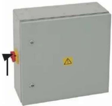
natural_image
Exterior view of a gray electrical enclosure with warning symbol and red arrow (no text or labels)8.2.6 SERVICE ACCESSES
All service accesses are from the front (service) side of the unit.
8.2.7 PERIODIC INSPECTIONS
Perform periodic inspections at least once a year as part of a summer service inspection. It is optimal to carry out inspections twice a year, usually before and after the end of the winter season.
During the regular service inspection it is necessary in particular:
- Perform regular inspection and cleaning of the heat exchange surfaces of the exchangers
– Clean or replace filter inserts in air filters - check the condition of the damping inserts, especially their tightness, and replace them in time
- Perform inspections and checks of the function of electrical components (contactors contacts, tightening of terminals, condition of insulation...)
- Check the hinges and supports of the device
- check the siphons for condensate drainage, especially their permeability and tightness, especially the tightness of the attachment to the unit and the tightness of the ball seating (in the case of overpressure siphons, fill the siphons with water)
- Carry out regular inspections of those facilities for which the applicable laws, decrees, standards and rules so require
- Keep proper records and monitoring of the outcome of inspections and revisions and monitor the implementation of the measures taken
8.2.8 SPARE PARTS
Warranty, post-warranty service and spare parts can be ordered from S&P UK Ventilation Systems Ltd. The manufacturer may entrust service to trained authorized service companies. Their list is at www.solerplau.co.uk. Contact details for authorized service are indicated on the yellow labels on each unit.
AUTHORIZED SERVICE

AUTHORISED SERVICE
S&P UK VENTILATION SYSTEMS LTD
01473 276890
technical.uk@solerpalau.com
WARNING - DO NOT OPERATE THE UNIT WHILE CONSTRUCTION WORK IN PROGRESS

WARNING
Do not turn on or use the unit when carrying out contraction work, as this risks irreversible damage including to the unit and the wiring! The product should only be operated by authorised persons. The manufacturer shall not be liable for damages incurred due to this, and the warranty will be void.
9. DECOMMISSIONING AND RECYCLING

EU law and our responsibility to future generations oblige us to recycle used materials; do not forget to dispose of all unwanted packaging materials at the appropriate recycling points and dispose of obsolete equipment at the nearest waste disposal site. In case of any questions regarding our products, please contact any branch of S&P UK Ventilation Systems Ltd.
To find your nearest dealer, visit our website www.solerplau.co.uk.
10. S&P LIMITED WARRANTY
24 (TWENTY-FOUR) MONTH PRODUCT WARRANTY
S&P UK Ventilation Systems Limited warrants that the DUOVENT will be free from defective materials and workmanship for the period of 24 (twenty-four) months from the date of original purchase. In the event that we find any part is defective the product will be repaired or at the company's discretion, replaced without charge provided that the product has been installed in accordance with the enclosed instructions and all applicable standards and national and local building standards.
IF CLAIMING UNDER WARRANTY
Please return the completed product, carriage paid, to your local authorised distributor. All returns must be accompanied with a valid Invoice of Sale. All returns must be clearly marked 'Warranty Claim', with an accompanying description stating the nature of the fault.
THE FOLLOWING WARRANTIES DO NOT APPLY
- Damages resulting from improper wiring or installation.
- Damages resulting when using the fan/control with fans/motors/controls/sensors other than those supplied and manufactured by the S&P Group of Companies.
- Removal or alteration of the S&P data plate label.
WARRANTY VALIDATION
- The end user must keep a copy of the Invoice of Sale to verify a purchase date.
- INSTRUCTION MANUAL
- Contents
- General 3
- General 4
- Technical data 4
- Transport, storage, acceptance....15
- Installation....17
- Electrical installation 35
- Commissioning 39
- Operation and maintenance....40
- Decommissioning and recycling 45
- Warranty....46
- GENERAL
- INTRODUCTION
- WARRANTY
- The warranty does not cover defects caused by:
- When claiming the warranty, it is necessary to submit a report containing:
- Warranty conditions
- SAFETY REGULATIONS
- GENERAL
- TECHNICAL DATA
- MANUFACTURING LABEL AND INFORMATION LABELS
- Order examples
- IMPORTANT NOTICE
- IMPORTANT WARNING!
- ATTENTION!
- DIRECTION OF AIR FLOW IN DUOVENT® MODULAR DV/RV UNITS:
- BASIC DIMENSIONS OF DUOVENT® MODULAR DV/RV UNITS
- GENERAL TECHNICAL DATA
- OPERATION CONDITIONS
- CAUTION!
- DECLARATION OF CONFORMITY
- TRANSPORT, STORAGE, ACCEPTANCE
- INSTALLATION
- PLACE OF INSTALLATION
- DISTANCES FROM BUILDING STRUCTURES (SERVICE SPACE)
- HOW TO STORE THE UNIT AT THE DESTINATION
- INSTALLATION PROCEDURE AND CONNECTION TO HVAC DISTRIBUTION LINES
- SAFETY INSTRUCTIONS FOR INSTALLATION
- CONNECTION TO AIR DISTRIBUTION LINES
- ELECTRIC HEATER CONNECTION (MARKED "DI" IN UNIT CODE)
- WATER HEATER CONNECTION (MARKED "DCA" OR "DCB" IN UNIT CODE)
- WATER COOLER CONNECTION (MARKED „DCC“ IN THE UNIT CODE)
- INFORMATION
- DIRECT EVAPORATOR CONNECTION (MARKED "DX" OR "DXR" IN UNIT CODE)
- CONDENSATE DRAIN CONNECTION
- BYPASS AND MIXING FLAP OF MODULAR DV UNITS
- MIXING FLAP OF DUOVENT® MODULAR RV
- INLET AND OUTLET FLAP OF DUOVENT MODULAR DV/RV
- BASIC ACCESSORIES OF DUOVENT® MODULAR DV/RV UNITS
- CONDENSATE DRAIN SIPHONS
- ESU WATER HEATER OR ESUCH WATER COOLER CONTROL UNIT
- ELECTRICAL INSTALLATION
- ELECTRIC HEATER CONNECTION
- INSTRUMENTATION AND CONTROL (I&C) SYSTEM
- DIGIREG® DIGITAL CONTROL SYSTEM
- TEMPERATURE REGULATION
- INSTALLATION
- TECHNOLOGY SCHEME OF DIGIREG® I&C SYSTEMS
- Legend to the diagrams:
- CONTROL
- COMMISSIONING
- INSTALLATION AND CONNECTION CHECK
- TRIAL OPERATION
- SAFETY INSTRUCTIONS FOR OPERATION AND MAINTENANCE
- EQUIPMENT SERVICE
- FILTER REPLACEMENT AND MAINTENANCE
- FAN REPLACEMENT AND MAINTENANCE
- MAINTENANCE OF RECOVERY PLATE EXCHANGER
- MAINTENANCE OF THE REGENERATION ROTATION EXCHANGER
- SERVICE SWITCH
- SERVICE ACCESSES
- PERIODIC INSPECTIONS
- SPARE PARTS
- DECOMMISSIONING AND RECYCLING
- S&P LIMITED WARRANTY
- (TWENTY-FOUR) MONTH PRODUCT WARRANTY
- IF CLAIMING UNDER WARRANTY
- THE FOLLOWING WARRANTIES DO NOT APPLY
- WARRANTY VALIDATION
Brand : Soler & Palau
Model : DUOVENT MODULAR DV
Category : Industrial fan