STAGE SETTER-8 - Regulator American DJ - Free user manual and instructions
Find the device manual for free STAGE SETTER-8 American DJ in PDF.


| Product Type | Lighting Controller / Regulator |
| Brand | American DJ |
| Model | STAGE SETTER-8 |
| Channels | 8 (individual channel faders) |
| Control Protocol | DMX-512 (3-pin XLR) |
| Control Modes | Manual, Sound Active, Auto, Chase |
| Chase Patterns | 8 built-in patterns |
| Blackout Button | Yes |
| Display | LED indicators for power, DMX, and channel activity |
| Power Supply | AC 100-240V, 50/60Hz (internal switching) |
| Power Consumption | 15W max |
| Dimensions (W x D x H) | 19 x 6.5 x 1.75 inches (482 x 165 x 44 mm), 1U rack mount |
| Weight | 4.5 lbs (2.0 kg) |
| Chassis Material | Steel with black finish |
| Connectors | 3-pin XLR DMX output, IEC power inlet |
| Sound Activation | Built-in microphone with sensitivity control |
| Speed Control | Adjustable for auto and chase modes |
| Fade Time Control | Adjustable fade between scenes |
| Flash Button | Master flash (full intensity) for all channels |
| Mounting | Standard 19-inch rack mount (brackets included) |
| Operating Temperature | 32°F to 104°F (0°C to 40°C) |
| Certifications | CE, ETL |
| Included Accessories | Power cord, user manual, rack mounting brackets |
Frequently Asked Questions - STAGE SETTER-8 American DJ
User questions about STAGE SETTER-8 American DJ
0 question about this device. Answer the ones you know or ask your own.
Ask a new question about this device
Download the instructions for your Regulator in PDF format for free! Find your manual STAGE SETTER-8 - American DJ and take your electronic device back in hand. On this page are published all the documents necessary for the use of your device. STAGE SETTER-8 by American DJ.
USER MANUAL STAGE SETTER-8 American DJ
©2016 ADJ Products, LLC all rights reserved. Information, specifications, diagrams, images, and instructions herein are subject to change without notice. ADJ Products, LLC logo and identifying product names and numbers herein are trademarks of ADJ Products, LLC. Copyright protection claimed includes all forms and matters of copyrightable materials and information now allowed by statutory or judicial law or hereinafter granted. Product names used in this document may be trademarks or registered trademarks of their respective companies and are hereby acknowledged. All non-ADJ Products, LLC brands and product names are trademarks or registered trademarks of their respective companies.
ADJ Products, LLC and all affiliated companies hereby disclaim any and all liabilities for property, equipment, building, and electrical damages, injuries to any persons, and direct or indirect economic loss associated with the use or reliance of any information contained within this document, and/or as a result of the improper, unsafe, insufficient and negligent assembly, installation, rigging, and operation of this product.
Europe Energy Saving Notice
Energy Saving Matters (EuP 2009/125/EC)
Saving electric energy is a key to help protecting the environment.
Please turn off all electrical products when they are not in use. To avoid power consumption in idle mode, disconnect all electrical equipment from power when not in use. Thank you!
Stage Setter 8 ^TM
Introduction
Introduction:
Thank you for purchasing the ADJ Stage Setter 8. ^™ To optimize the performance of this product, please read these operating instructions carefully to familiarize yourself with the basic operations of this unit. The ADJ Stage Setter 8 ^™ is a unique 16 channel DMX controller. This unit has been tested at the factory before being shipped to you, there is no assembly required.
Customer Support:
ADJ Products, LLC provides a toll free customer support line, to provide set up help and to answer any question should you encounter problems during your set up or initial operation. You may also visit us on the web at www.adj.com for any comments or suggestions.
Service Hours are Monday through Friday 8:00 a.m. to 4:30 p.m. Pacific Standard Time.
Voice: (323) 582-2650
Fax: (323) 582-2941
E-mail: support@AmericanDJ.com
Warning! To prevent or reduce the risk of electrical shock or fire, do not expose this unit to rain or moisture.
Caution! There are no user serviceable parts inside this unit. Do not attempt any repairs yourself, doing so will void your manufactures warranty. In the unlikely event your unit may require service please contact your nearest ADJ dealer.
Do not discard this cartoon in the trash. Please recycle when ever possible.
Upon unpacking, carefully inspect your unit for any damage that may have occurred during shipping. If damage may have occurred, do not plug the unit in, please contact your dealer as soon as possible.
Stage Setter 8 ^TM
Contents
Introduction....2
Features....4
Overview....5
Set-Up....6
Frt Panel Controls and Functions....8
Rear Panel Controls and Functions....13
General Operation:
Operating Modes....15
Master Scenes....15
Flash Scenes....16
Programming Chase Patterns:
2x8 and 8x8 Modes....17
1x16 Mode....18
MIDI Operation....19
LCD Value Change....20
Memory Dump....20
Warranty....21
Technical Specifications....22
Improvements and changes in specifications and design to this manual and unit may be made at any time without prior notice.
Stage Setter 8 ^TM
Introduction
FEATURES:
Stage Setter 8 ^TM features include:
• 3-pin XLR IN, OUT, and THRU DMX jacks
- Three different operating modes: 2 x 8, 8 x 8, and 1 x 16
• 12 pattern option: 4 built in and 8 user programmable
• 32 steps (scenes) per a program
- MIDI compatible
- Fog machine output button
- Scene crossfader
- Tap SYNC button
- 8 Bump Buttons
- Back up memory protection
• Full functional, 4 digit LCD display
Stage Setter 8 ^TM
Introduction
WARNINGS:
- Do not spill water or other liquids in to or on to your unit.
- Be sure that the local power outlet match that of the required voltage for your unit.
- Do not attempt to operate this unit if the power cord has been frayed or broken. Please route your power cord out of the way of foot traffic.
- Do not attempt to remove or break off the ground prong from the electrical cord. This prong is used to reduce the risk of electrical shock and fire in case of an internal short.
- Disconnect from main power before making any type of connection.
- Do not remove the top cover under any conditions. There are no user serviceable parts inside.
- Disconnect the unit's main power when left unused for long periods of time.
- Never plug this unit in to a dimmer pack
- Always be sure to mount this unit in an area that will allow proper ventilation. Allow about 6" (15cm) between this device and a wall.
- Do not attempt to operate this unit, if it becomes damaged in any way.
- Never operate this unit when it's cover is removed.
- To reduce the risk of electrical shock or fire, do not expose this unit rain or moisture
- This unit is intended for indoor use only, use of this product outdoors voids all warranties.
- During long periods of non-use, disconnect the unit's main power.
• Always mount this unit in safe and stable matter.
Stage Setter 8 ^TM
Set Up
Unpacking:
Every Stage Setter 8 ^™ has been thoroughly tested and has been shipped in perfect operating order. Carefully check the shipping carton for damage that may have occurred during shipping. If the carton appears to be damaged, carefully inspect your fixture for any damage. In the case damage has been found please contact our toll free customer support number for further instructions.
Power Supply:
Before plugging your unit in be sure the source voltage in your area matches the required voltage for your ADJ Stage Setter 8. ^™ The ADJ ^® Stage Setter 8 ^™ is available in a 115v and 230v version. Because line voltage may vary from venue to venue, you should be sure to plug your unit into a matching wall outlet before attempting to operate you controller.
Data Cable (DMX Cable) Requirements:
Your controller and packs require a standard 3-pin XLR connector for DMX data input and DMX data output (Figure 1). If you are making your own cables be sure to use standard two conductor shielded cable (This cable may be purchased at almost all pro sound and lighting stores). Your cables should be made with a male and female XLR connector on either end of the cable. Also remember that DMX cable must be daisy chained and can not be "Y"ed or split.
Notice: Do not use the ground lug on the XLR connector. Do not connect the cable's shield conductor to the ground lug or allow the shield conductor to come in contact with the XLR's outer casing. Grounding the shield could cause a short circuit and erratic behavior.
Notice: Be sure to follow figures two and three when making your own cables.

ADJ Products, LLC - www.adj.com - Stage Setter 8™ Instruction Manual Page 6
Stage Setter 8 ^TM
Set Up
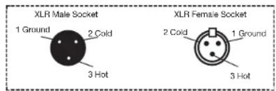
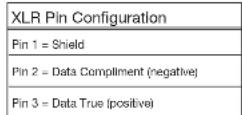
Figure 3
Special Note: Line Termination.
When longer runs of cable are used, you may need to use a terminator on the last unit to avoid erratic behavior. A terminator is a 90-120 ohm 1/4 watt resistor which is connected between pins 2 and 3 of a male XLR connector (DATA + and DATA -). This unit is inserted in the female XLR connector of the last unit in your daisy chain to terminate the line. Using a cable terminator will decrease the possibilities of erratic behavior.

Termination reduces signal errors and avoids signal transmission problems and interference. It is always advisable to connect a DMX terminal. (Resistance 120 Ohm 1/4 W) between PIN 2 (DMX-) and PIN 3 (DMX +) of the last fixture.
Figure 4
ADJ Products, LLC - www.adj.com - Stage Setter 8™ Instruction Manual Page 7
Stage Setter 8™ Front Panel Controls and Functions Front Panel
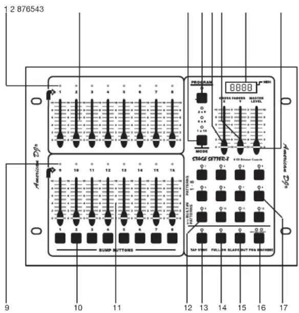
- Channel LEDs (1-8):
These 8 LEDs detail the current intensity for channel sliders 1-8. The more you raise the channel slider the higher the output. The LED indicators will directly reflect the changes in slider level. - Scene X - Channel Faders 1-8:
These 8 sliders are used to control the intensities of channel 1-8. The overall intensity of channel faders 1-8 is controlled by the X Crossfader (5). - Mode Button:
This button is used to change the unit's operating mode. There are three different operating modes: 2x8, 8x8, and 1x16. The
ADJ Products, LLC - www.adj.com - Stage Setter 8™ Instruction Manual Page 8
Stage Setter 8 ^TM Front Panel Controls and Functions
unit's current operating mode will indicated by a LED. that corresponds to the operating mode icons. Mode operations are explained on page 15.
4. Program Button:
This button is used to activate the unit's program mode. You may create up to eight of your own programs. These programs are then stored on the Pattern Buttons (17). See programing on page 17.
When the Program Button is depressed the program LED will begin to glow, this indicates Program Mode has been activated.
Once Program Mode is activated you may begin to program chase patterns or static scenes into the eight user Pattern Buttons (17). For programming details, see the programming section beginning on page 17.
5. X Crossfader:
This slider controls the overall intensity of the Scene X channel faders (2).
The X (5) and Y (6) faders allow crossfading between Scenes X (2) and Scene Y (11) The X Crossfader is at its maximum intensity while in the full up position.
In 1x16 mode, the X Crossfader controls the intensities of channels 1-16
6. Y Crossfader:
This slider controls the overall intensity of the Scene Y channel faders (11).
The X (5) and Y (6) faders allow crossfading between Scenes X (2) and Scene Y (11) The Y Crossfader is at its maximum intensity while in the full down position.
In 1x16 mode, the Y Crossfader controls the scene Fade Time.
The offset configuration of the X (5) and Y (6) crossfaders allows easy
ADJ Products, LLC - www.adj.com - Stage Setter 8™ Instruction Manual Page 9
Stage Setter 8 ^TM Front Panel Controls and Functions
dipless crossfading between scenes, providing both crossfaders are moved together.
7. LCD Display:
This multifunctional display will detail the unit's current operation. The LCD will indicate an active MIDI signal by flashing a LED next to the MIDI icon.
8. Master Level Slider:
This slider controls the overall channel intensity levels for channel sliders, 1-16 (2 & 11), and will also control the master intensity level for programs 1-12 (12 & 17). This slider will have no effect on the Full On (14) and Bump (10) functions.
For example;
When the Master Slider is at minimum all output will be zero, except for any resulting from the Bump Buttons (10) and Full On Button (14). Zero output will be indicated by the LCD Display (7), again with the exception of any output resulting from the Bump Buttons (10) and Full On Button (14). If the slider is at 50%, all outputs will be at 50%. The LCD (7) will display 50% output. If the slider is at 10, all outputs will be 100%. This will be indicated by 100 in the LCD Display (7).
9. Channel LEDs (9-16):
These 8 LEDs detail the current intensity for channel sliders 9-16. The more you raise the channel slider the higher the output. The LED indicators will directly reflect the changes in slider level.
10. Bump Buttons:
Each of the eight Bump Buttons can be programmed to control a single or a group of channels (1-16). The eight buttons can then be used to bring an individual or group of channels to full intensity.
The 8 momentary Bump Buttons are used to bring each individual channel to full intensity regardless of the Blackout (15) function or the Master Level (8) setting.
Stage Setter 8 ^TM Front Panel Controls and Functions
In 1x16 mode, each button can be programmed to control a group of channels, this makes each button a Flash Scene.
The Bump Buttons are also used in programming mode, when programming Flash Scenes and Master Scenes.
11. Scene Y:
These 8 sliders are used to control the intensities of channel 9-16 (11). The overall intensity of channel faders 9-16 (11) is controlled by the X Crossfader (5).
12. Built-in Patterns 9-12:
These four Patterns buttons are used to activate any of the four built in programs stored in the unit's memory. A pattern LED will glow when a corresponding pattern was selected for operation.
13. Tap Sync:
This button is used to create a chase rate. Repeatedly tapping this button will establish a chase rate that corresponds to your tap rate. The chase rate will be synchronized to the time interval of the last two taps. A Tap Sync LED will flash at the established chase rate. A chase rate may be set at anytime, weather a chase pattern is running or not.
The Tap Sync Button also activates Step Mode. Holding the Tap Sync button down for at least five seconds will activate Step Mode. To deactivate Step Mode hold down the Tap Sync button for five seconds.
14. Full On Button:
This button is used to bring all channel output (1-16) to full intensity. This function will override the Blackout (15) function. A Full On LED (14) will glow when Full On (14) is active.
15. Blackout Button:
This button is used to disable all channel output (1-16). Only the Full On (14) and Bump Buttons (10) function can override this function. Blackout is active when the Blackout LED is glowing.
Stage Setter 8™ Front Panel Controls and Functions
- Fog Machine Button:
This button is used to control fog output to compatible ADJ fog machine. These fog machine include the Master Blaster 700 and 1000, Vaporizer, and the Dyno Fog. This button not only eliminates the need of a separate fog machine controller, but also allows quick and easy access to a fog machine output. For an updated list of compatible fog machines please contact our support department.
- Patterns 1-8:
These buttons are used to access any of the eight patterns you may create yourself. A pattern LED will glow when a corresponding pattern was selected for operation.
Stage Setter 8 ^TM Rear Panel Controls and Functions
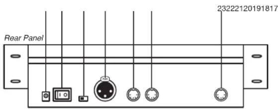

Rear Panel - Controls and Functions
- DC Power Input:
This jack is used to connect to external power supply. Only use the included DC 12\~20V, 500 mA minimum power supply. If it becomes necessary to replace the original power supply, only use an approved ADJ power supply.
- Power Switch:
This switch is used to turn the unit's main power On/Off.
- DMX Polarity Select:
This switch is used to change the unit's DMX pin polarity. Polarity can be changed from pin 2 hot to pin 3 hot and vice versa. The ability to change the units DMX polarity was incorporated to accommodate older DMX packs that may follow a pin 2 hot standard.
- DMX Out:
This XLR jack is used to send DMX data to your DMX dimmer
Stage Setter 8™ Rear Panel Controls and Functions
packs or other DMX fixtures.
- MIDI Thru:
This jack is used to parallel an incoming MIDI signal through to another MIDI device.
- MIDI In:
This jack receives an incoming MIDI signal from external MIDI controller or keyboard.
- Fog Machine Connector:
Use this connection to connect a compatible ADJ fog machine, such as the Master Blaster 700 and 1000, Vaporizer, and the Dyno Fog. This eliminate the need of separate controller.
Stage Setter 8 ^TM
General Operation
Operating Modes:
The Stage Setter 8 ^TM has three different operating modes: 2x8, 8x8, and 1x16. These modes are selected with the Mode Button (3). The current mode is indicated by the Mode LED (3).
In 2x8 mode, Crossfader X (5) controls the channels 1-8, and Crossfader Y (6) controls channels 9-16.
In 8x8 mode, the Scene Y (11) channels (9-16) become a set of Masters Scenes. Each Master Scene channel (9-16) will control the level of the scenes or patterns created. The Scene X (2) channels (1-8) operate as normal dimmer sliders.
In 1x16 mode, X Crossfader (5) controls the intensities of channels 1-16, and Y Crossfader controls the Fade Time. Fade Time is the amount of time it takes one scene to end and fade in to the next. Fade Time varies from 1/10 of second (instant) to 10 minutes.
Masters Scenes:
Master Scenes is function that can only be used while in the 8x8 operating mode. When in the 8x8 mode, the Bump Buttons (10) and the Scene Y (11) sliders can be used to store a Masters Scene. A Master Scene consist of channels 1-8.
To create a Master Scene:
First, use the sliders in the Scene X (2) section to create a scene. After you have set your scene, tap the Program Button to enter the program mode. Once Program mode has been activated, tap the Bump Button that corresponds to a Scene Y (11) slider that will be used to store the scene. The scene will now be stored as a Master Scene into the Scene Y slider and will be ready for immediate use.
Example:
We will program a into the fifth Master Scene. The scene will consist of channels 1 and 6 at full, channel 7 at 50% and the remaining channels fully off.
Stage Setter 8 ^TM
General Operation
- Move X and Y Crossfaders to maximum.
(X Crossfader fully up and Y Crossfader fully down)
- Lower all Scene X sliders to minimum.
- Raise Scene X slider 1 and 6 to maximum.
- Raise Scene X slider 7 to 50%.
- Tap the Program Button. The Program LED should be lit.
- Tap Bump Button 5.
Flash Scenes:
Flash Scenes that only operates in 1x16 mode. When in the 1x16 mode, the Bump Buttons (10) can be programmed as Flash Scenes. These are scenes that can be created by any of the 16 channels. Once a Flash Scene is created this scene may be activate by pressing on the Bump Button it was assigned to. create a Flash Scene:
First, use the sliders in the Scene X (2) and Scene Y (11) section to create a scene. After you have set your scene, tap the Program Button to enter the program mode. Once Program mode has been activated, tap the Bump Button that corresponds to a Scene Y slider that will be used to store the scene. The scene will now be stored as a Master Scene into the Scene Y slider and will be ready for immediate use.
Example:
In this example we will program Bump Button 8, allowing channels 3, 7, 14 and 15 to be at full, channel 1, 5, 10 and 16 at 50% output and the remaining channel fully off.
- Move all Scene X and Scene Y sliders to fully down.
- Move Scene X sliders 3 and 7 to fully up.
- Move Scene Y sliders 14 and 15 to fully up.
- Move Scene X sliders 1 and 5 to 50%.
- Move Scene Y sliders 10 and 16 to 50%.
- Tap the Program Button causing its LED to light.
- Tap Bump Button 8.
Stage Setter 8 ^TM
Basic Programming
Programming Chase Patterns:
You may create up to 8 Chase Patterns consisting of up to 32 steps (scenes). These patterns are stored in to the Pattern Buttons (17).
To initiate programming, first tap the Program Button (14) so that the Program to activate program mode, the program LED will glow when program mode is activated. Once program mode is activated tap the Pattern Button (17) you wish to program to. Once you selected a pattern bank to store your program the corresponding pattern LED will begin to flash indicating which Pattern Button (17) was selected. You may now begin the program process.
Programming Chase Patterns (2x8 and 8X8 modes):
When in the 2x8 or 8x8 mode, each pattern can only be programmed using Scene X Sliders (2), and each step will only include Channels 1-8.
Example:
Programming a 32 step pattern into the Pattern 5 Bank Button using the Scene X Sliders (2).
- Tap the Program Button (4), the program LED will begin to glow.
- Tap the Pattern 5 Button (17), the Pattern 5 LED will begin flashing.
- Move the desired Scene X Sliders (17) to the levels desired as the first step of this pattern.
- Tap the Program Button (4) to program this step into memory, all channel LED should flash once and the LCD (7) will read "01".
- Repeat steps 3 and 4 until the LCD (7) reads "end." End will denote the maximum of 32 steps has been reached.
- After the maximum of 32 steps has been programmed, program mode will automatically release.
- If you wish to program less steps in to your program, you can
Stage Setter 8 ^TM
Basic Programming
exit the program mode manually y by tapping on the Black-out Button (15) once. This will manually release the program mode.
NOTE:
While in program mode, all other functions will lock.
Programming Chase Patterns (1x16 mode):
When in the 1x16 mode, both the Scene X (1-9) and the Scene Y Channels (9-16) can be used.
Example:
Program a 4 step pattern with channels 7-10 at full in sequence in to the Pattern 6 Button using both the Scene X (2) and Scene Y (11) sliders.
- Be sure you are in the 1x16 mode. If not, use the Mode Button (3) to select 1x16 operation.
- Tap the Program Button (4), the program LED will begin to glow.
-
Tap the Pattern 5 Button (17), the Pattern 5 LED will begin flashing.
-
Move all Scene X (2) and Scene Y (11) sliders to fully down.
-
Move Scene X slider 7 to the full intensity position.
-
Tap the Program Button (4) once, the LCD (7) will read "01".
-
Move Scene X slider 8 to the full intensity position.
-
Tap the Program button once, the LCD (7) will read "02".
-
Move Scene Y slider 9 to the full intensity position.
-
Tap the Program Button (4) once, the LCD (7) will read "03".
-
Move Scene Y slider 10 to the full intensity position.
-
Tap the Program Button (4) once, the LCD (7) will read "04".
-
Tap the Blackout Button (15) once to exit the program mode, the Program LED (4) will turn off.
-
To test your program press the Pattern 6 Button. Your four step chase pattern will begin to run.
Stage Setter 8 ^TM
MIDI Operation
MIDI Settings:
To change adjust the MIDI settings:
- Be sure main power is off.
- With main power off hold down Bump Buttons 1-4. With Bump Button 1-4 held down, turn main power on. Once main power is on the current MIDI Receive channel will be displayed in the LCD.
- Tap Bump Button 8 to change the MIDI Receive channel. The MIDI receive channels can range from channels 1-16.
- Tap the Blackout Button to exit MIDI Setting mode.
MIDI Implementation:
This console receives MIDI program changes according the following table:
NOTE NUMBER VELOCITY FUNCTION
22-37 Channel intensity Turn on or off channels 1-16
38-45 Turn on or off Bump Button 1-8
46-57 Turn on or off Pattern 1-12
58 Mode
59 Full On
60 Blackout
Stage Setter 8 ^TM
LCD Value
LCD Display Value:
The LCD display can be changed to read in DMX channel values (1-255) or to read in dimmer percentage value (1-100). To change the LCD value:
- Be sure main power is off.
- With main power off hold down Bump Buttons 1-4. With Bump Button 1-4 held down, turn main power on. Once main power is on the current MIDI Receive channel will be displayed in the LCD.
- Tap Bump Button 7 to select the display value from 255/100.
- Tap the Blackout Button to exit the adjustment mode.
Stage Setter 8 ^TM
Memory Dump
Memory Dump:
This functions allows you to reset the unit's default settings. Caution: This will erase all user programs. To reset the unit:
- Be sure main power is off.
- Hold Bump Buttons 2, 3, 6, and 7 down.
- While holding down the above Bump Buttons turn main power on. 4. The unit will now return to the default settings.
Stage Setter 8 ^TM
Warranty
MANUFACTURER'S LIMITED WARRANTY
A. ADJ Products, LLC hereby warrants, to the original purchaser, ADJ Products, LLC products to be free of manufacturing defects in material and workmanship for a prescribed period from the date of purchase (see specific warranty period on reverse). This warranty shall be valid only if the product is purchased within the United States of America, including possessions and territories. It is the owner's responsibility to establish the date and place of purchase by acceptable evidence, at the time service is sought.
B. For warranty service you must obtain a Return Authorization number (RA#) before sending back the product-please contact ADJ Products, LLC Service Department at 800-322-6337. Send the product only to the ADJ Products, LLC factory. All shipping charges must be pre-paid. If the requested repairs or service (including parts replacement) are within the terms of this warranty, ADJ Products, LLC will pay return shipping charges only to a designated point within the United States. If the entire instrument is sent, it must be shipped in its original package. No accessories should be shipped with the product. If any accessories are shipped with the product, ADJ Products, LLC shall have no liability whatsoever for loss of or damage to any such accessories, nor for the safe return thereof.
C. This warranty is void if the serial number has been altered or removed; if the product is modified in any manner which ADJ Products, I.I.C concludes, after inspection, affects the reliability of the product; if the product has been repaired or serviced by anyone other than the ADJ Products, LLC factory unless prior written authorization was issued to purchaser by ADJ Products, LLC; if the product is damaged because not properly maintained as set forth in the instruction manual.
D. This is not a service contract, and this warranty does not include maintenance, cleaning or periodic check up. During the period specified above, ADJ Products, LLC will replace defective parts at its expense with new or refurbished parts, and will absorb all expenses for warranty service and repair labor by reason of defects in material or workmanship. The sole responsibility of ADJ Products, LLC under this warranty shall be limited to the repair of the product, or replacement thereof, including parts, at the sole discretion of ADJ Products, LLC. All products covered by this warranty were manufactured after August 15, 2012, and bear indentifying marks to that effect.
E. ADJ Products, LLC reserves the right to make changes in design and/or improvements upon its products without any obligation to include these changes in any products theretofore manufactured.
No warranty, whether expressed or implied, is given or made with respect to any accessory supplied with products described above. Except to the extent prohibited by applicable law, all implied warranties made by ADJ Products, LLC in connection with this product, including warranties of merchantability or fitness, are limited in duration to the warranty period set forth above. And no warranties, whether expressed or implied, including warranties of merchantability or fitness, shall apply to this product after said period has expired. The consumer's and/or Dealer's sole remedy shall be such repair or replacement as is
expressly provided above; and under no circumstances shall ADJ Products, LLC be liable for any loss or damage, direct or consequential, arising out of the use of, or inability to use, this product.
This warranty is the only written warranty applicable to ADJ Products, LLC Products and supersedes all prior warranties and written descriptions of warranty terms and conditions heretofore published.
MANUFACTURER'S LIMITED WARRANTY PERIODS:
- Lighting Products = 1-year (365 days) Limited Warranty (Such as: Special Effect Lighting, Intelligent Lighting, UV lighting, Strobes, Fog Machines, Bubble Machines, Mirror Balls, Par Cans, Trussing, Lighting Stands etc. excluding LED and lamps)
- Laser Products = 1 Year (365 Days) Limited Warranty (excluding laser diodes which have a 6 month limited warranty)
• L.E.D. Products = 2-year (730 days) Limited Warranty (excluding motors, PCB boards, and power applies, which have a 1-year (365 day Limited Warranty) batteries which have a 180 day limited warranty). Only the L.E.D.s carry a 2-year warranty (excluding StarTec Series which a carries a 1 Year Limited Warranty) Note: 2 Year Warranty only applies to purchases within the United States. - ADJ DMX Controllers = 2 Year (730 Days) Limited Warranty (excluding faders and tact switches)
ADJ Products, LLC - www.adj.com - Stage Setter 8™ Instruction Manual Page 21
Stage Setter 8 ^TM Technical Specifications
Technical Specifications:
DC Input.....DC 12\~20V, 500 m A min.
DMX OUT....3-pin XLR female
MIDI In/Thru....5 pin multiple socket
Patterns......12 patterns, including 8 programmable patterns and 4 built-in patterns
Steps....Up to 32 steps for each pattern
Dimensions....310x222x71mm
Weight....2.4 Kg
ADJ Products, LLC
6122 S. Eastern Ave. Los Angeles, CA 90040 USA
Tel: 323-582-2650 / Fax: 323-582-2941
Web: www.adj.com / E-mail: info@americandj.com
Follow Us On:


facebook.com/americandj
twitter.com/americandj
youtube.com/adjlighting
A.D.J. Supply Europe B.V.
Junostraat 2
6468 EW Kerkrade
The Netherlands
support@adjgroup.eu / www.adj.com
Tel: +31 45 546 85 00 / Fax: +31 45 546 85 99
- Stage Setter 8 TM
- Introduction
- Introduction:
- Customer Support:
- Do not discard this cartoon in the trash. Please recycle when ever possible.
- Contents
- FEATURES:
- WARNINGS:
- Set Up
- Unpacking:
- Power Supply:
- Data Cable (DMX Cable) Requirements:
- Special Note: Line Termination.
- Stage Setter 8 TM Front Panel Controls and Functions
- Program Button:
- X Crossfader:
- Y Crossfader:
- LCD Display:
- Master Level Slider:
- For example;
- Channel LEDs (9-16):
- Bump Buttons:
- Scene Y:
- Built-in Patterns 9-12:
- Tap Sync:
- Full On Button:
- Blackout Button:
- Stage Setter 8™ Front Panel Controls and Functions
- Stage Setter 8 TM Rear Panel Controls and Functions
- Rear Panel - Controls and Functions
- Stage Setter 8™ Rear Panel Controls and Functions
- General Operation
- Flash Scenes:
- Example:
- Basic Programming
- Programming Chase Patterns:
- Programming Chase Patterns (2x8 and 8X8 modes):
- NOTE:
- Programming Chase Patterns (1x16 mode):
- MIDI Operation
- MIDI Settings:
- MIDI Implementation:
- NOTE NUMBER VELOCITY FUNCTION
- LCD Value
- LCD Display Value:
- Memory Dump
- Memory Dump:
- Warranty
- MANUFACTURER'S LIMITED WARRANTY PERIODS:
- Stage Setter 8 TM Technical Specifications
Brand : American DJ
Model : STAGE SETTER-8
Category : Regulator