
TruVu TV-UC561 - Régulateur CARRIER - Free user manual and instructions
Find the device manual for free TruVu TV-UC561 CARRIER in PDF.


| Product Type | Building Automation Controller (Regulator) |
| Brand | Carrier |
| Model | TruVu TV-UC561 |
| Dimensions (H x W x D) | Approximately 5.0 x 5.5 x 2.0 in. (127 x 140 x 51 mm) |
| Weight | Approximately 1.2 lb (0.54 kg) |
| Power Supply | 24 VAC/VDC ±10%, Class 2 |
| Power Consumption | Typical 10 W, maximum 15 W |
| Operating Temperature | 32°F to 122°F (0°C to 50°C) |
| Storage Temperature | -22°F to 158°F (-30°C to 70°C) |
| Relative Humidity | 0% to 90% non-condensing |
| Communication Protocols | BACnet/IP, BACnet MS/TP, Modbus, N2, Istat, and web services |
| Inputs/Outputs | 16 universal inputs, 16 outputs (configurable digital or analog) |
| Functions | HVAC control, zone control, equipment scheduling, data logging, alarm management |
| Mounting | DIN rail or screw mounting |
| Programming | Via TruVu Workbench software (free) |
| Display | None; LED indicators for status |
| Maintenance and Cleaning | Keep enclosure closed; clean with a dry cloth; avoid liquids |
| Safety | Install according to local electrical codes; disconnect power before servicing |
| Spare Parts and Repairability | Contact Carrier technical support; modular design allows field replacement of I/O modules |
| General Information | Part of Carrier TruVu family; designed for commercial building automation; supports integration with Carrier systems |
Frequently Asked Questions - TruVu TV-UC561 CARRIER
User questions about TruVu TV-UC561 CARRIER
0 question about this device. Answer the ones you know or ask your own.
Ask a new question about this device
Download the instructions for your Régulateur in PDF format for free! Find your manual TruVu TV-UC561 - CARRIER and take your electronic device back in hand. On this page are published all the documents necessary for the use of your device. TruVu TV-UC561 by CARRIER.
USER MANUAL TruVu TV-UC561 CARRIER
Installation and Start-up Guide
Carrier

Verify that you have the most current version of this document from www.hvacpartners.com, the Carrier Partner
Community website, or your local Carrier office.
Important changes are listed in Document revision history at the end of this document.
©2023 Carrier. All rights reserved.
Contents
What Is the TV-UC561? 1
Specifications....2
Zone sensors ....5
Touchscreen devices....6
To mount the TV-UC561....7
Wiring for power 8
To wire for power 8
Addressing the TV-UC561 through the Service port 9
To set the IP address....10
Addressing a network of controllers using the controller setup Local Network tab ....12
Method 1: To address when you know the serial numbers .... 12
Method 2: To address when you do not know the serial numbers....13
Wiring for communications....14
Wiring specifications....14
To connect the TV-UC561 to the Ethernet.... 15
Wiring devices to the TV-UC561's Rnet port....16
Wiring devices to the TV-UC561's Act Net port 17
Wiring Inputs and outputs....18
Inputs....18
Outputs....18
Wiring specifications....19
To wire inputs and outputs....20
To adjust input and output properties 23
Input values 23
Output values 24
Resolution values 25
Offset/Polarity values 25
Find and upload in the i-Vu® interface....27
Adjusting the TV-UC561 driver properties 28
Driver 28
Device 29
Notification Classes....30
Calendars 31
Common Alarms....31
Specific Events 32
Custom Translation Tables....33
BACnet Controller Properties....33
BACnet Firewall....33
Network Diagnostics - Statistics....34
Network Diagnostics - Packet Capture 35
Act Net Bus 36
Communication Status....38
Flow Calibration Archive .... 38
To set up Network Statistic trends....38
To set up the controller through the Service port ....40
ModStat tab 40
Device tab 41
Ports tab 42
BACnet tab 42
Contents
Security tab....42
Local Network tab....42
To communicate through the BACnet/Service port network....46
To communicate locally through the Rnet port....48
To set up a Local Access connection in the i-Vu® interface 49
Troubleshooting....50
LEDs 50
To configure custom Prog LED 52
To get a Module Status report 52
Troubleshooting inputs and outputs....52
To get a Device Log 54
To get the TV-UC561's serial number 54
To replace the TV-UC561's fuse.... 54
To revert to default settings....55
To take the TV-UC561 out of service 56
Compliance 57
FCC Compliance 57
CE and UKCA Compliance 57
Industry Canada Compliance....57
BACnet Compliance....57
Appendix - Module Status field descriptions ....58
Document revision history 60
What is the TV-UC561?
The TruVu™ Advanced Application Controller (part no. TV-UC561):
- Runs one control program
- Supports BACnet/IP communications on the 10/100 Ethernet port as a single node in a daisy-chain configuration or as part of a network using a ring topology
• Supports DHCP IP addressing - Has built-in network diagnostic capture functionality for troubleshooting
- Has network statistics that can be viewed numerically or as trend graphs
• Supports Rnet devices
• Supports Act Net devices - Works with the i-Vu® v7.0 or later system with the latest cumulative patch
• Works with Field Assistant v7.0 or later with the latest cumulative patch - Provides 6 universal inputs, 5 binary outputs, and 1 universal output
• The universal output can be configured as binary, analog, or pulse-width modulated analog
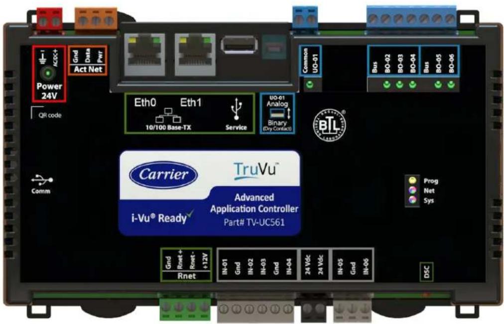
You can use the TV-UC561's physical communication ports as follows:
| Port | Port type | For this type of communication... | At... |
| Eth0 | 10/100 Mbps Ethernet | BACnet/IP | 10 or 100 Mbps |
| Eth1 | BACnet/Ethernet |
The TV-UC561 also has the following ports:
- Rnet port for connecting ZS sensors, an Equipment Touch, an TruVu™ ET Display, and Wireless Adapter for wireless sensors
- Service USB port for connecting locally to controller setup pages, the TruVu™ ET Display, or the Carrier wireless service adapter
• Comm USB port for other communication options in the future -
Act Net port supports a combination of up to 5 Act Net addresses, as follows:
-
Address 1 is reserved for the Carrier actuator
- Address 2 and 3 are reserved for the VAV Zone II Secondary Duct
- Address 4 and 5 for i-Vu® Smart Valves
Specifications
| Driver | drv_fwex_< version >.driverx |
| Maximum number of control programs* | 1 |
| Maximum number of BACnet objects* | 12000 |
| Third-party BACnet integration points | 100 |
| NOTE Must be on the BACnet/IP network | |
* Depends on available memory.
| Power | 24 Vac ±15%, 50–60 Hz, 55 VA24 Vdc ±10%, 20 WNOTE The above power consumption is for the controller only. Adding devices to the Act Net bus increases total power consumed. |
| Eth0, Eth1 | 10/100 BaseT, full duplex, Ethernet ports for BACnet/IP and/or BACnet/Ethernet, or Modbus TCP/IP communication.Under normal operation, network traffic not destined for this controller is repeated to the other Ethernet port. When the controller is powered off, all traffic received on one port is mirrored to the other port. |
| Rnet port | Supports up to 5 wireless and/or ZS sensors, and one Equipment Touch or TruVuTM ET DisplaySupplies 12 Vdc/260 mA power to the Rnet across its rated temperature range.NOTE Ambient temperature and power source fluctuations exceeding the listed operating ranges may reduce the power supplied by the Rnet port.NOTE If the total power required by the sensors on the Rnet exceeds the power supplied by the Rnet port, use an external power source. The Wireless Adapter, Equipment Touch, or TruVuTM ET Display must be powered by an external power source. See the specifications in each device's Installation and Start-up Guide to determine the power required. |
| Act Net port | Supports a combination of up to 5 Act Net addresses, as follows:Address 1 is reserved for the Carrier actuatorAddress 2 and 3 are reserved for the VAV Zone II Secondary DuctAddress 4 and 5 for i-Vu® Smart ValvesMaximum power available for Act Net devices:AC supply - 25 VA (1 A)DC supply - 15W (0.625A)Use an external transformer if your devices exceed the maximum power. |
| Service port | USB 2.0 host port for setting up the controller and troubleshooting through a local connection to a computer, connecting to the TruVuTM ET Display, or the Carrier wireless service adapter. |
| USB Comm port | For future use. |
| Universal inputs | 6 |
| Inputs are configurable in the control program for 0–5 Vdc, 0–10 Vdc, thermistor, dry contact, or pulse counter. | |
| Input resolution | 12 bit A/D |
| Input pulse frequency | 10 pulses per second. Minimum pulse width (on or off time) required for each pulse is 50 msec. |
| 24 Vdc terminal | Supplies 24 Vdc to external I/O devices, max 100 mA |
| Universal output | This output can be set by a DIP switch as an Analog or Binary output.In Analog mode, the output can be used for 0-10 Vdc or a 12 Vdc pulse width modulated (PWM) control signal at a frequency of 80 Hz.In Binary mode, the output has a built-in relay and can be used to switch external devices or relays up to 3.75A, 30 Vac/Vdc. |
| Binary outputs | 2 banks of bussed outputs, 3 N.O. binary outputs on one bank, 2 N.O. binary outputs on the other. Each relay contact rated at 3.75 A max. @ 30 Vac/Vdc. Each bank is limited to Class 2 requirements of 100 VA / 4.2 A. Configured normally open.See Output values (page 24). |
| Output resolution | 12 bit D/A |
| Controller microprocessor | 32-bit ARM Cortex-A8, 600MHz, processor with multi-level cache memory |
| Memory | 4 GBs eMMC Flash memory and 256 MB DDR3 DRAM (2 MB available).User data is archived to non-volatile Flash memory when parameters are changed, every 90 seconds, and when the firmware is deliberately restarted.NOTE When you change a parameter, you must wait 30 seconds before turning the power off, in order for the change to be saved. |
| Real-time clock | Real-time clock keeps track of time in the event of a power failure for up to 3 days. |
| Protection | A single fast acting, 5mm x 20mm glass fuse for powerThe power and network ports comply with the EMC requirements EN50491-5-2.[2xxx]CAUTION To protect against large electrical surges on serial EIA-485 networks, place a PROT485 at each place wire enters or exits the building. |
| LED status indicators | See LEDs (page 50) for details.Tricolor Net LED to show network statusTricolor Sys LED to show controller statusTx (Transmit) and Rx (Receive) activity LED and yellow link status LED for the following ports:○ Ethernet port Eth0○ Ethernet port Eth1Output LEDs indicate status of each output.Prog LED is customizable. |
| Environmental operating range | -40 to 158°F (-40 to 70°C), 10-95% relative humidity, non-condensing NOTESThe TV-UC561 is suitable for installation inside or outside the building envelope.Install in a UL Listed enclosure only.Do not change the position of the End of Net switch at temperatures below - 22°F (-30C) to ensure proper operation and electrical connectivity. |
| Physical | Fire-retardant plastic ABS, UL94-5VA |
| Terminal blocks and connectors | Screw-type terminal blocks.0.2 in (5.08 mm) pitch connectors |
| Mounting | 35mm DIN rail mounting or screw mounting |
| Overall dimensions | A: 7.78 in. (19.77 cm)B: 5.88 in. (14.94 cm)Depth: 2.00 in. (5.09 cm) |
| Screw mounting dimensions | C: 5.3 in (13.45 cm)D: 4.50 in. (11.43 cm) |
| Weight | 1.2 lbs (0.54 kg) |
| BACnet support | Conforms to the BACnet Advanced Application Controller (B-AAC) and B-BBMD Standard Device Profiles as defined in ANSI/ASHRAE Standard 135-2012 (BACnet) Annex L, Protocol Revision 14 |
| Compliance | United States of America:FCC CFR, Part 15, Class B |
| Canada:Industry Canada Compliant, ICES-003, Class AcUL Listed UL 916, PAZX7, Energy Management Equipment | |
| Europe: UKMark, UK: EN50491-5-2:2009; Part 5-2: EMC requirements for HBES/BACS used in residential, commercial and light industry environmentRoHS Compliant: 2015/863/EUREACH CompliantAustralia and New Zealand: RCM Mark, AS/NZS IEC 61000-6-3 |
Zone sensors
You can wire ZS sensors and/or a Wireless Adapter that communicates with wireless sensors to the TV-UC561's Rnet port. You can have up to 5 ZS and/or wireless sensors.
NOTES
• One control program can use no more than 5 ZS sensors.
- ZS and wireless sensors can share the Rnet with an Equipment Touch or TruVu™ ET Display.

CAUTION Rnet power
The Rnet port provides 12 Vdc at up to 260 mA. When determining which devices to put on the Rnet, verify that the total current draw of the sensors does not exceed the controller's Rnet power. See the sensor's Installation and Start-up Guide to determine the power required.
Touchscreen devices
You can connect the TV-UC561 to the touchscreen devices using the Rnet port or the USB Service port.
Rnet port
You can wire an Equipment Touch or TruVu™ ET Display to the TV-UC561's Rnet port to view or change the controller's property values, schedule equipment, view trends and alarms, and more, without having to access the system's server. The Rnet port can have one Equipment Touch or TruVu™ ET Display, plus ZS sensors and/or a Wireless Adapter that communicates with wireless sensors.
NOTE These touchscreen devices are not powered by the Rnet port.
• The TruVu™ ET Display requires a 24 Vdc external power source.
- The Equipment Touch requires a 24 Vac external power source.
USB port
You can connect the TruVu™ ET Display to the TV-UC561's USB Service port to view or change the controller's property values, schedule equipment, view trends and alarms, and more, without having to access the system's server.
NOTES
• These touchscreen devices are not powered by the USB port.
• The TruVu™ ET Display requires a 24 Vdc external power source.

CAUTION A touchscreen device can share a power supply with the Carrier controller if:
• The power source shared by the controller and Equipment Touch is AC power.
- The power source shared by the controller and TruVu™ ET Display is DC power.
- You maintain the same polarity.
- You use the power source only for Carrier controllers.
To mount the TV-UC561
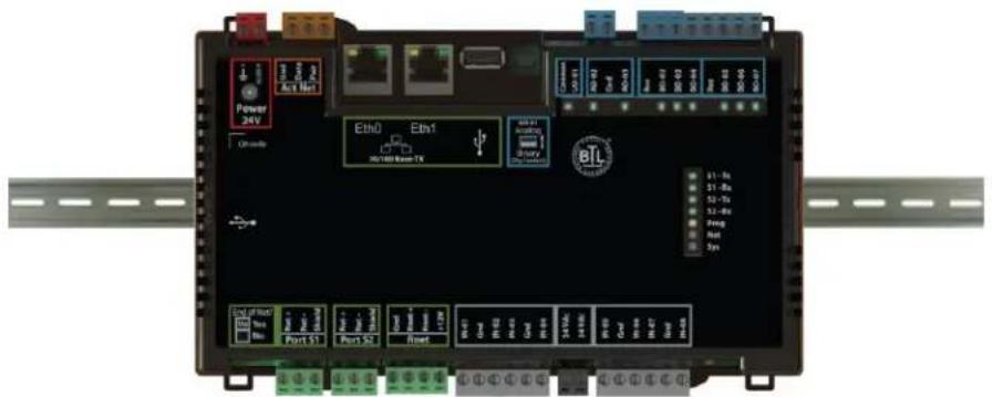
The TV-UC561 can be mounted on a DIN rail or screwed to a surface.
DIN rail mount
1 In the trough on the back of the controller, hook the edge of the DIN rail under the controller's two mounting flanges.
2 Push the controller toward the DIN rail until you hear it click and the spring-loaded latch secures the controller to the DIN rail.
Screw Mount
Leave about 2 in. (5 cm) on each side of the controller for wiring.
Pull the mounting tabs until they click in place. Insert #6 screws through them. Use no more than 12 in lbs. torque to secure plastic tab to mounting surface. Use flat washers to prevent the screw head from deforming the plastic.
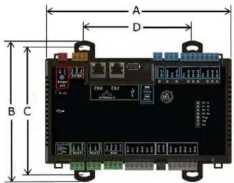
| A: | 7.78 in. (19.77 cm) |
| B: | 5.88 in. (14.94 cm) |
| C: | 5.3 in. (13.45 cm) |
| D: | 4.50 in. (11.43 cm) |
| Depth: | 2.00 in (5.08 cm) |
Wiring for power

WARNING Do not apply line voltage (mains voltage) to the controller's ports and terminals.

CAUTIONS
- The TV-UC561 is powered by a Class 2 power source. Take appropriate isolation measures when mounting it in a control panel where non-Class 2 circuits are present.
- Carrier controllers can share a power supply as long as you:
- Maintain the same polarity.
- Use the power supply only for Carrier controllers.
To wire for power
1 Remove power from the power supply.
2 Pull the red screw terminal connector from the controller's power terminals labeled 24V.
3 Connect the power supply's wires to the red screw terminal connector.
4 Connect an 18 AWG or larger wire from the power supply's negative (-) terminal to earth ground. This wire must not exceed 12 in. (30.5 cm).
5 Apply power to the power supply.
6 Measure the voltage at the red screw terminal connector to verify that the voltage is within the operating range of 20.4 to 28.8 Vac or 21.6 to 28.8 Vdc.
7 To verify the polarity of the wiring, measure the voltage from the negative terminal of the red screw terminal connector to a nearby ground. The reading should be 0V.
8 Insert the red screw terminal connector into the controller's power terminals.
9 Verify that the LED on top of the controller is on.
Addressing the TV-UC561 through the Service port
The TV-UC561 is addressed using the controller setup pages. The Local Network tab allows you to discover all i-Vu® XT or TruVu™ devices on a single network and configure them from that page. See Addressing a network of controllers using the controller setup Local Network tab (page 12) and the Local Network (page 42) tab.
You can connect the TV-UC561 to a computer using either the Carrier wireless service adapter or a USB cable.
NOTE You cannot access the Service port by plugging an Ethernet cable into Eth0 or Eth1.

CAUTION The USB local access cable provides a common ground connection between the computer and the controller it connects to. Damage to the controller and possibly the computer's USB port will occur if the controller's input power polarity was not maintained and was also not properly grounded (floating). If you are not sure of the wiring polarity and that the controller was properly grounded, use a USB isolator between the computer and the controller.
To connect the TV-UC561 to a computer using the Carrier wireless service adapter:
1 Insert the Carrier wireless service adapter (part# USB-W) into the controller's USB Service Port to communicate with a Wi-Fi-compatible computer.

CAUTION If the Eth1 port is in use, connect a USB Type-A Male to Female extension cable to the USB ce Port and the Carrier wireless service adapter.
2 Open your computer's wireless network display to view your available wireless networks.
NOTE TV-UC561 only supports the 5 GHz band and not the 2.4 GHz band.
3 Connect to the wireless network using the network SSID and password that are printed on the Carrier wireless service adapter.
4 Open a web browser on the computer and navigate to http://local.access or http://169.254.1.1 to see the controller setup pages.
To connect the TV-UC561 to the computer using a USB cable.
1 Connect a USB Type-A Male to Male USB cable from a computer to the controller's USB Service Port, as shown below.
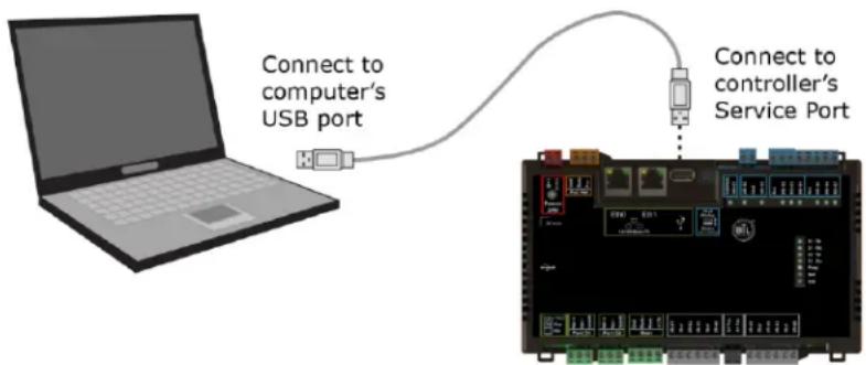
2 A new Ethernet connection will appear on your computer.
3 If your computer uses a static IP address, use the following settings for the new connection:
- Address: 169.254.1.x, where x is 2 to 7
- Subnet Mask: 255.255.255.248
Default Gateway: 169.254.1.1
If it uses a DHCP address, leave the address as it is.
4 Open a web browser on the computer
5 Navigate to http://local.access or http://169.254.1.1 to see the controller setup pages.
See To set up the controller through the Service Port (page 40) for detailed information.
To set the IP address
You must define the TV-UC561's IP addressing (IP address, subnet mask, and default gateway) on the controller setup Ports tab so that the controller can communicate with the i-Vu Server on the IP network.
Use one of the IP addressing schemes described below with the associated instructions that follow.
| Use a... | If... |
| DHCP IP Address generated by a DHCP server | The IP network uses a DHCP server for IP addressing |
| Custom Static IP Address from your network administrator | You do not use a DHCP server and the answer to any of the following questions is yes. Will the i-Vu® system:Share a facility's existing IP data network?Be connected to the Internet?Have at least one device located on the other side of an IP router?Be connected to any third-party IP devices? |
NOTE Carefully plan your addressing scheme to avoid duplicating addresses. If third-party devices are integrated into the system, make sure your addresses do not conflict with their addresses.
To set a DHCP IP address
1 On the controller setup Modstat tab, find the controller's Ethernet MAC address and write it down.
2 On the Ports tab under IP Port, select DHCP.
3 Click Save.
4 Write down the IP Address.
5 Give the DHCP network administrator the IP address and Ethernet MAC address and ask him to reserve that IP address for the controller so that it always receives the same IP address from the DHCP server.
To set a custom static IP address
1 Obtain the IP address, subnet mask, and default gateway address for the controller from the facility network administrator.
2 On the controller setup Ports tab under IP Port, select Custom Static.
3 Enter the IP Address, Subnet Mask, and Default Gateway addresses given to you by the network administrator.
4 Click Save.
Addressing a network of controllers using the controller setup Local Network tab
You can use the controller setup Local Network tab to discover Carrier i-Vu® XT or TruVu™ devices on a single network. You can configure them and assign addresses to each one using one of the methods described below.
NOTE For this discovery tool to work, the controllers must reside on the same subnet and be downloaded with drv_fwex_107-xx-xxxx or later.
Method 1: To address when you know the serial numbers
1 Connect one i-Vu® XT or TruVu™ device on the IP network to the Service port. For details, see Addressing the TV-UC561 through the Service port (page 9).
NOTE This device is referred to as the "connected controller".
2 Browse to the Service Port address (http://local.access or http://169.254.1.1).
3 On the Ports tab, set the device's IP Address, Subnet Mask, and Default Gateway.
4 On the controller setup Local Network tab, verify that the device's address information is displayed at the top of the page.
5 On the Local Network tab, click the Clear All button to erase the Local Devices table if there is information in it.
6 Click Discover. The table finds and lists the first 256 unconfigured devices on the same subnet. The table is sorted by serial number.
NOTE A maximum of 256 i-Vu® XT or TruVu™ controllers can be discovered and displayed in the Local Devices table. If you have more than 256 controllers on your network, configure some or all the controllers in the table and click Clear. Check Only Unconfigured and click Discover again. A count appears above the table to report the total number of controllers and the discovered number.
7 To configure devices:
One at a time - Enter the IP Address and Location or name (optional) of each device you wish to configure. When you enter the IP address, that device inherits the original device's subnet mask and default gateway.
Multiple devices simultaneously - Select the devices you want to address, enter the starting IP address in the field under the Address heading, and then click Assign. The selected devices are automatically assigned sequential IP addresses.
NOTE To change the IP Address, the device's Mode must be Custom Static.
For more details about discovering and configuring your devices, see Local Network tab (page 42).
Method 2: To address when you do not know the serial numbers
You will need physical access to each device so that you can press the DSC button on the bottom right of the TV-UC561. This allows you to identify the device on the controller setup Local Network page.
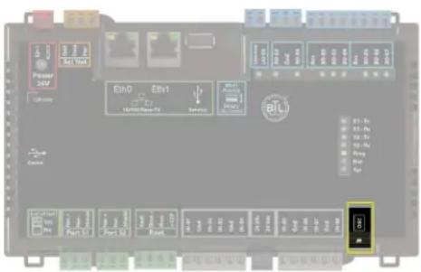
1 Connect to the Service Port of one i-Vu® XT or TruVu™ IP device on the network. For details, see Addressing the TV-UC561 through the Service port (page 9).
2 Browse to the Service Port address (http://local.access or http://169.254.1.1).
3 On the Ports tab, set the device's IP Address, Subnet Mask, and Default Gateway.
NOTES The other devices that you configure inherit this device's subnet mask and default gateway.
4 On the Local Network tab, click the Clear All button to erase any pre-existing data in the Local Devices table.
5 On the controller you want to address, press the DSC button on the bottom right. When pressed, a row appears in the Local Devices table on the Local Network tab. The row has a blue dot to indicate which controller has just had the button pressed.
6 In the row for the identified controller, enter the Address and Location (optional).
7 Repeat steps 3 and 4 for each controller that you want to address.
8 For more details about discovering and configuring your devices, see Local Network tab (page 42).
NOTE To physically identify a device that is displayed on the Local Devices table, you can click the Blink button, which causes that device's Net and Sys LEDs to flash light blue for 10 seconds.
The following are two possible methods you could use to identify and assign a network of controllers' addresses after following steps 1 - 4 above.
- Two technicians can work together if they are communicating throughout the process. The first technician physically travels around the building to each controller, tells his co-worker exactly where he is, and then presses the DSC button. The second technician, who is sitting at a computer connected to the controller, watches for the blue dot to show up on the Local Devices table on the Local Network tab, where he can enter the appropriate addressing and identifying information.
- One technician alone can address the controllers on a mobile device showing the Local Network page by plugging the Carrier wireless service adapter into a controller's Service Port. Then, with the computer, move to each controller within 100 ft. of the adapter. Pressing the DSC button on the controller displays a blue dot in the table where the addressing information can be entered.
Wiring for communications
The TV-UC561 communicates on the following ports.
| Port | Protocol | Port type(s) | Speed(s) |
| Eth0 | BACnet/IP | Ethernet | 10 or 100 Mbps |
| Eth1 | BACnet/Ethernet | ||
| Service port * | USB 2.0 | USB | |
| Comm Port (future use) | USB 2.0 | USB | |
| Rnet Port | See Wiring devices to the TV-UC561's Rnet port (page 16). | ||
| Act Net Port | See Wiring devices to the TV-UC561's Act Net port (page 17). | ||
* See To set up the controller through the Service port (page 40).
Wiring specifications
| For... | Use... | Maximum Length |
| Ethernet - not daisy chained | Cat5e or higher Ethernet cable | 328 feet (100 meters) |
| Ethernet - a daisy chain configuration | Cat5e or higher Ethernet cable | 164 feet (50 meters) |

WARNINGS
- Do not apply line voltage (mains voltage) to the controller's ports and terminals.
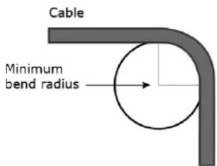
- Do not exceed the minimum bend radius of the Cat5e or Cat6e Ethernet cable. Refer to Ethernet cable manufacturer specifications for minimum bend radius.
To connect the TV-UC561 to the Ethernet
Connect an Ethernet cable from the building BAS system or another TV-UC561 controller to the Eth0 Ethernet port. If necessary, connect another Ethernet cable from the Eth1 port to the next TV-UC561 controller in a daisy chain.
The TV-UC561 has a fail-safe Ethernet relay that bypasses a daisy chained controller in the event of an internal disruption, such as a power loss. When a failure occurs and the switch is bypassing a controller, the network connection on both sides of the controller are electrically connected, which continues the signal and passes it to the next controller.
NOTE If your system has controllers on different IP subnets separated by an IP router, you must configure one controller on each subnet as a BACnet Broadcast Management Device (BBMD). Do not configure more than one BBMD per subnet as this may cause circular routes. See "Setting up BACnet Broadcast Management Devices (BBMDs)" in SiteBuilder or i-Vu® Help.
Wiring devices to the TV-UC561's Rnet port
You can wire the following devices to the TV-UC561's Rnet port in a daisy-chain configuration:
- ZS sensors
- Wireless Adapter that communicates with wireless sensors
- Equipment Touch
- TruVu™ ET Display
See the device's Installation and Start-up Guide for complete wiring instructions.
NOTES
• ZS sensors, a Wireless Adapter, and an Equipment Touch can share the same Rnet.
- The Rnet communicates at a rate of 115.2 kbps.
Wiring devices to the TV-UC561's Act Net port
Supports a combination of up to 5 Act Net addresses, as follows:
• Address 1 is reserved for the Carrier actuator
- Address 2 and 3 are reserved for the VAV Zone II Secondary Duct
• Address 4 and 5 for i-Vu® Smart Valves
Maximum power available for Act Net devices:
• AC supply - 25 VA (1 A)
• DC supply - 15W (0.625A)
- Use an external transformer if your devices exceed the maximum power.

CAUTIONS
If the power source for the Act Net devices require a connection to earth ground, you must place it in the same control panel as the TV-UC561 controller, so that it shares a common earth ground reference, thereby reducing the potential for ground loops.
A remote Act Net power source, installed near the Act Net devices, should be floating (no local connection to earth ground).
The TV-UC561 provides an orange, three-pin removable screw terminal connector for the Act Net port.
Be careful to wire the Act Net port terminals on the controller to the matching terminal on the supported device. They may not be in the same order. See example below.
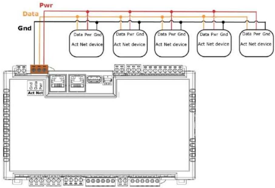
flowchart
graph TD
    A["Act Net"] --> B["Data Pwr Gnd Act Net device"]
    A --> C["Data Pwr Gnd Act Net device"]
    A --> D["Data Pwr Gnd Act Net device"]
    A --> E["Data Pwr Gnd Act Net device"]
    A --> F["Data Pwr Gnd Act Net device"]
    B --> G["Gnd"]
    C --> H["Gnd"]
    D --> I["Gnd"]
    E --> J["Gnd"]
    F --> K["Gnd"]
    style A fill:#f9f,stroke:#333
    style B fill:#ccf,stroke:#333
    style C fill:#ccf,stroke:#333
    style D fill:#ccf,stroke:#333
    style E fill:#ccf,stroke:#333
    style F fill:#ccf,stroke:#333
The TV-UC561 supports Act Net communication to the Act Net devices on a bus with a maximum length of 300 feet (91.44 meters). The bus should be wired with copper conductors of an appropriate size (18 AWG or larger) to compensate for voltage drop and ensure that bus voltage does not drop below 19.2 Vac or 21.6 Vdc.
Wiring inputs and outputs
Inputs
The TV-UC561 has inputs that accept the following signal types.
| Signal Type | Description |
| Thermistor1 | Precon Type 2 (10kOhm at 77 °F)Input voltages should be from 0.2 Vdc to 4.0 Vdc for thermistors |
| Dry contact | The maximum current when the contact is closed is 0.5 mA. The input voltage should be 4.1 V when the contact is open. Maximum closed contact resistance is 1kOhms. |
| 0-5 Vdc0-10 Vdc | The input impedance of the TV-UC561 is approximately 120 kOhm when configured as a voltage input. |
| Pulse counter2 | Pulse counting up to 10 pulses per second.Minimum pulse width (on or off time) required for each pulse is 50 msec. |
^1 To use a thermistor not listed above, you can set up a custom translation table (page 33) for your sensor in the controller's driver.
^2 The TV-UC561 can perform pulse counting for Dry Contact or Binary Input if you assign the input to a Pulse to Analog Input microblock. See To adjust input and output properties.
Outputs
Analog outputs
Analog outputs can be used for 0-10 Vdc devices. Resistance to the ground must be 500 Ohms minimum.
NOTE The device must share the same ground as the controller.
Binary outputs
There are 2 banks of relays. One bank contains 3 built-in relays, and the other bank contains 2 built-in relays. The relays have dry contacts that share a common bus input. An external voltage source must be wired to the common bus connection for each bank of relays.
Each relay can be used to switch the voltage provided on its associated bus terminal to an external device or relay. Each relay can switch up to 3.75 A, 30 Vac/Vdc. The total power and current that can be switched by a bank of 3 relays cannot exceed the Class 2 limits of 100 VA or 4.2 A.
Universal output
The TV-UC561's universal output can be set as analog or binary using the Analog/Binary DIP switch located to the left of the output terminals.
When the DIP switch is in the Analog position, the universal output can be used for pulse-width modulated (PWM) control of devices, such as electrically commutated motors. When used in pulse-width mode, the output voltage is 12 Vdc and the frequency is locked at 80 Hz. Use a BAO microblock to enable this.
NOTE The PWM output signal is intended to directly control the speed of an ECM-type fan, eliminating the need for an external converter board.

WARNING Do not apply voltage to the universal output if the DIP switch is set to Analog.
Wiring specifications
Input wiring
| Input | Maximum length | Minimum gauge | Shielding |
| ThermistorDry contact | 1000 feet(305 meters) | 22 AWG | Shielded |
| 0-5 Vdc0-10 Vdc | 1000 feet(305 meters) | 26 AWG | Shielded |
| Pulse counterTLO | 1000 feet(305 meters) | 22 AWG | Shielded |
Output wiring
To size output wiring, consider the following:
- Total loop distance from the controller to the controlled device
NOTE Include the total distance of actual wire. For 2-conductor wires, this is twice the cable length.
- Acceptable voltage drop in the wire from the controller to the controlled device
- Resistance (Ohms) of the chosen wire gauge
• Maximum current (Amps) the controlled device requires to operate
To wire inputs and outputs

WARNING Do not apply line voltage (mains voltage) to the controller's ports and terminals.
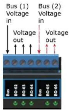
The Gnd terminal is shared by the inputs/outputs to the right and left of it.
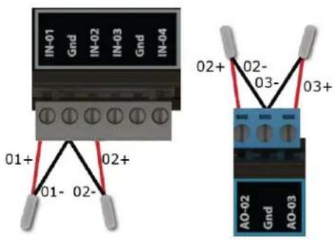
The TV-UC561 has connections for two separate busses.
1 Verify that the TV-UC561's power and communications connections work properly.
2 Turn off the TV-UC561's power.
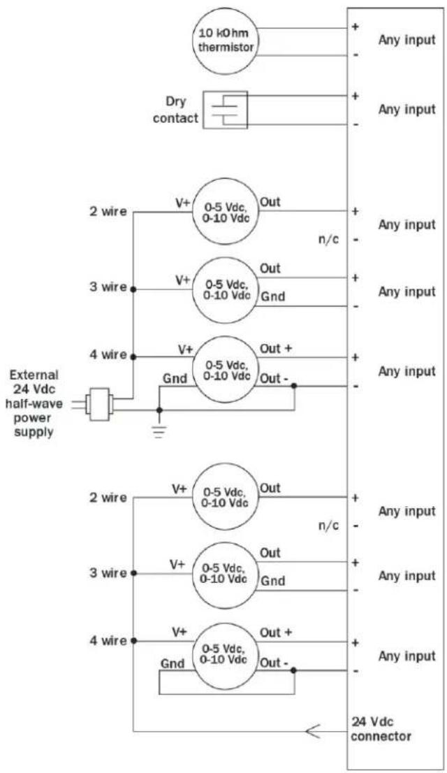
3 Connect the input wiring to the screw terminals on the TV-UC561.
NOTE Connect the shield wire to the - terminal with the ground wire. Do not connect the shield wire at the other end of the cable as this will cause a ground loop error.
4 If you are using the UO, set the universal output's DIP switch to Binary or Analog for the type of device wired to the output.

ERNINGS
The universal output is set to Binary in the factory. To avoid damage to the controller, use a voltmeter to verify there is no voltage on the UO-01 (+) and Common (-) terminals before setting the DIP switch to Analog.
Do not apply voltage to the universal output if the DIP switch is set to Analog.
5 Connect binary and analog output wiring to the screw terminals on the TV-UC561 and to the controlled device.
6 Connect the ground wire to the AO outputs' terminals.
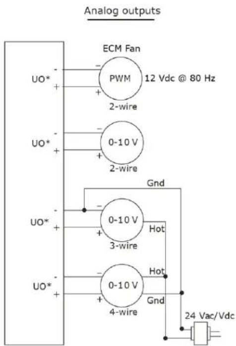
*Applicable when UO-01 is configured as an analog output.
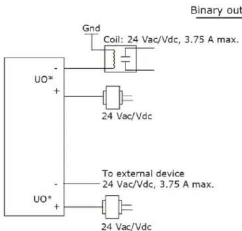
*Applicable when UO-01 is configured as a binary output.
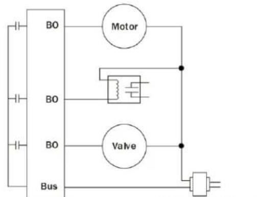
24 Vac/Vdc, 3.75 A max.
7 Turn on the TV-UC561's power.
See Troubleshooting inputs and outputs (page 52).
NOTE You can install connector covers (sold separately, part #PLM-KIT) by snapping them over the terminal block sections on the top and bottom of the controller.
To adjust input and output properties
An input or output must be assigned to its corresponding point in the control program. This is typically done when the control program is created, but you can adjust the settings at the time of installation in the i-Vu® interface.
1 In the i-Vu® navigation tree, select the equipment controlled by the TV-UC561.
2 On the Properties page, select the I/O Points tab.
3 In each point's Num field, type the number of the controller's corresponding input or output. For example, if you use UO1 on the TV-UC561 for the point Pump S/S, type 1 in the Num field for Pump S/S.
NOTES
• Exp (expander number) is 00 for the inputs and outputs located on the TV-UC561.
- Do not assign the same output number to more than one point.
4 Enter the appropriate values for each input and output in the remaining columns. See Input values, Output values, Resolution values and Offset/Polarity values below.
5 If you have not performed the initial download to the attached controller, you must download now to verify inputs and outputs.
6 To verify each input's operation, force each sensor to a known value, then compare it to the Value shown on the Properties page on the I/O Points tab.
7 To verify each output's operation, lock each output to a known condition on the I/O Points tab, then verify that the equipment operates correctly.
See Troubleshooting inputs and outputs (page 52).
Input values
| Input | I/O Type | Sensor/Actuator Type | Min/Max |
| Analog (BAI) | |||
| 0-5 Vdc | 0-5 Volt | Linear Full Range | Engineering values associated with 0 Vdc (Min) and 5 Vdc (Max) ^1 |
| No Translation | N/A. The input microblock's value will be the raw voltage of the input. | ||
| 0-10 Vdc | 0-10 Volt | Linear Full Range | Engineering values associated with 0 Vdc (Min) and 10 Vdc (Max) ^1 |
| No Translation | N/A. The input microblock's value will be the raw voltage of the input. | ||
| 2-10 Vdc | 0-10 Volt | Linear w/Offset, 2-10 Volts | Engineering values associated with 2 Vdc (Min) and 10 Vdc (Max) ^1 |
| Thermistor | Thermistor | Select your Thermistor type or set up and select a Non-Linear, Custom Table ^2 | N/A |
| Pulse to Analog (BPTA)3 | |||
| Pulse Counter | Dry Contact or Binary Input | N/A | N/A |
| Binary (BBI) | |||
| Dry Contact | Dry Contact | N/A | N/A |
^1 The sensor reads a value and sends a corresponding signal (Volts) to the TV-UC561's physical input. The Analog Input microblock uses the Min and Max values to linearly translate the signal into the engineering value used in subsequent control logic.
^2 You can set up a custom translation table (page 33) on the driver's Custom Translation Tables pages in the i-Vu® interface.
^3 The control program must have one Pulse to Analog Input microblock for each pulse counting input.
Output values
| Output | I/O Type | Sensor/Actuator Type | Min/Max |
| Analog (BAO) | |||
| 0-10 Vdc | Electrical0–10 Volt | Linear Full Range | Engineering values associated with 0 Vdc (Min) and 10 Vdc (Max) ^1 |
| No Translation | N/A. The Analog Output microblock will output the same value that comes in to the microblock. | ||
| 2-10 Vdc | Electrical0–10 Volt | Linear w/Offset,2–10 Volts | Engineering values associated with 2 Vdc (Min) and 10 Vdc (Max) ^1 |
| Binary (BBO) | |||
| Relay | Relay/TriacOutput | N/A | N/A |
| Universal (BBO or BAO) | |||
| 0-10 Vdc | Electrical0–10 Volt | Linear Full Range | Engineering values associated with 0 Vdc (Min) and 10 Vdc (Max) |
| No Translation | N/A. The Analog Output microblock will output the same value that comes in to the microblock. | ||
| 2-10 Vdc | Electrical0–10 Volt | Linear w/Offset,2–10 Volts | Engineering values associated with 2 Vdc (Min) and 10 Vdc (Max) |
| Relay | Relay/TriacOutput | N/A | N/A |
| 12 Vdc PWM | PWM 80 Hz | No Translation | 0% (Min) and 100% (Max). The Analog Output microblock will vary the width of the pulse based on the value that comes into the microblock. |
^1 The Analog Output microblock uses the Min and Max values to linearly translate its incoming value into a physical output signal (Volts) sent from the TV-UC561 to a device. For example, set Min to 0 and Max to 100 for an Analog Output microblock that receives a 0 to 100% open signal from a PID microblock and that controls a 0–10 Vdc actuator so that when the PID signal is 100%, the TV-UC561 output is 10 Vdc. Similarly, when the PID signal is 50%, the TV-UC561 output is 5 Vdc.
Resolution values
Resolution is not particular to a type of input or output, but the driver handles analog and binary inputs and outputs differently. To set these values appropriately, you should understand how the driver uses them.
| Resolution | Notes |
| Analog Input (BAI) | The driver rounds the microblock's present value according to the resolution. EXAMPLE If the calculated present value is 13.789 and you set the Resolution to 0.1, the control program uses 13.8 for any calculations downstream from the microblock. |
| Analog Output (BAO) | The driver rounds the wire input value to the microblock before performing any scaling calculations. EXAMPLE If the wire input value is 13.789 and you set the Resolution to 0.1, the microblock uses 13.8 for any scaling calculations. |
Offset/Polarity values
Offset/Polarity is not particular to a type of input or output, but the driver handles analog and binary inputs and outputs differently. To set these values appropriately, you should understand how the driver uses them.
| Offset/Polarity | Notes |
| Analog Input (BAI) | Offset value (positive or negative) adds a fine adjustment to a sensor reading after all scaling for calibration. EXAMPLE If a sensor reads 74.9°F when the actual measured value is 73.6°F, enter an Offset of -1.3 to calibrate the sensor to the measured value. |
| Analog Output (BAO) | You can use the Offset value (positive or negative) to calibrate an output, but you generally do not need to. If used, the driver adds the offset value to the wire input value before performing any scaling calculations to determine the TV-UC561's output. |
| Binary Input (BBI) | Polarity determines the microblock's present value when no signal is received from the equipment.When no signal is received from the equipment, if Polarity is set to:normal–present value is offreversed–present value is on |
| Binary Output (BBO) | Polarity determines the TV-UC561's output based on the control program's signal to the microblock.When the control program's signal to the microblock is on, if Polarity is set to:normal–output is onreversed–output is offNOTE Regardless of Polarity, the output will be off if the TV-UC561 loses power. |
Find and upload in the i-Vu® interface
1 In the i-Vu® interface, select the System level in the navigation tree.
2 On the Devices page > Manage tab, click Find Devices to discover your routers and their drivers, graphics, and touch files.
3 Once routers are found, select one or more routers in the list on the Manage tab and click Upload All Content to upload to the i-Vu® application. Use Ctrl+click, Shift+click, or both to select multiple items.
4 Click OK when you see the message This will upload all content for the controller. Are you sure you want to do this?. When complete, a check mark under Status indicates a successful upload.
NOTES
- If an error message appears, click on the message to view an explanation.
- For details, see the i-Vu® Help.
Adjusting the TV-UC561 driver properties
After you find and upload the TV-UC561 in the i-Vu® interface, you may want to customize the TV-UC561's settings for your applications. You can change settings on the Driver Properties page.
1 In the i-Vu® interface, right-click the TV-UC561 in the navigation tree and select Driver Properties.
2 Adjust the driver as desired.
Driver
The Driver page provides the following information plus the items described in the table below:
• The date/time of last parameter change or the last time the database was archived
• If control programs, properties, and schedules were successfully stored in memory
• The date/time of last backup and restore
• Undelivered Alarm Status
TouchScreen Control
| TouchScreen Schedule Edit Enable | Check this field to allow a user to edit this controller's schedules from an Equipment Touch or System Touch Schedules screen.NOTE Schedules edited on an Equipment Touch or System Touch are not uploaded to the i-Vu® application. This could result in the controller operating on a schedule that differs from the one you see in the i-Vu® interface. |
| Controller Clock | |
| Clock Fail Date and Time | Date and time the controller uses when its real-time clock is invalid. |
| Time Synch Sensitivity (seconds) | When the controller receives a time sync request, if the difference between the controller's time and the time sync's time is greater than this field's value, the controller's time is immediately changed. If the difference is less than this field's value, the controller's time is slowly adjusted until the time is correct. |
| Network Microblocks | |
| BACnet third party Integration points capacity, integration points requested, and integration points active | Shows how many third-party BACnet points the TV-UC561 allows (capacity), how many points are in the control program (requested), and how many are currently active (not disabled in i-Vu®).For example, if the controller allows 400 points, the control program has 350 points, and you disabled 30 points in i-Vu®, you will see:Integration points capacity: 400Integration points requested: 350Integration points active: 320 |
| Number of poll retries before Network Input Microblocks indicate failure | The maximum number of retries after the initial attempt that a Network microblock will attempt to communicate with its target device. If unsuccessful, the point will transition to an idle state for 30 seconds before attempting to communicate again. Change this field only if directed by Technical Support. |
| Periodic reblnding interval | If a microblock uses a wildcard in its address, this timer determines how often the microblock will attempt to find the nearest instance of its target. For example, if an outside air temperature address uses a wildcard, a VAV application will look for the outside air temperature on the same network segment or on the nearest device containing that object. |
| BACnet COV Throttling | |
| Enable COV Throttling | Under normal circumstances, COV Throttling should be enabled to prevent excessive network traffic if an object's COV Increment is set too low. See EXCEPTION below.When enabled, if an object generates excessive COV broadcasts (5 updates in 3 seconds), the driver automatically throttles the broadcasts to 1 per second. Also, if the object's value updates excessively for 30 seconds, an alarm is sent to the i-Vu® application listing all objects that are updating excessively. A Return-to-normal alarm is sent only after all objects have stopped updating excessively.EXCEPTION: In rare circumstances, such as process control, a subscribing object may require COV updates more frequently than once per second. For these situations, clear this checkbox, but make sure that your network can support the increased traffic. You will also need to disable the Excessive COV alarms under the driver's Common Alarms. |
| Trend Sampling | |
| Collect a daily midnight sample for all points in this controller that are sampling on COV | For values that change infrequently, select to verify at midnight daily that the point is still able to communicate trend values. |
| Local Network Configuration | |
| Allow Local Network Configuration from other devices on the local network for 24 hours | You can unlock a device for 24 hours to make IP address changes. |
| Disable Eth1 Port | |
| Disable Eth1 Port | Check this box to disable the Eth1 port. |
| Debug | |
| Enable Debug Messages | Enable only if directed by Carrier Control Systems Support. |
Device
The Device page provides the following information plus the items described in the table below:
• BACnet device object properties for the TV-UC561
• The character sets supported by this device for BACnet communication
• The controller clock's time and date
| Configuration | |
| BACnet System Status | The current state of the controller:OperationalDownload in ProgressDownload RequiredBackup in ProgressNon-Operational |
| The following fields refer to all networks over which the TV-UC561 communicates. | |
| APDU Timeout | How many milliseconds the device waits before resending a message if no response is received. |
| APDU Segment Timeout | How many milliseconds the device waits before resending a message segment if no response is received. |
| Number of APDU Retries | The number of times the device resends a message. |
Notification Classes
A BACnet alarm's Notification Class defines:
- Alarm priority for Alarm, Fault, and Return to Normal states
- Options for BACnet alarm acknowledgment
• Where alarms should be sent (recipients)
Alarms in the i-Vu® application use Notification Class #1. The i-Vu® application is automatically a recipient of these alarms.
| Priorities | NOTE BACnet defines the following Network message priorities for Alarms and Events. | |
| Priority range | Network message priority | |
| 00-63 | Life Safety | |
| 64-127 | Critical Equipment | |
| 128-191 | Urgent | |
| 192-255 | Normal | |
| Priority of Off-Normal | BACnet priority for Alarms. | |
| Priority of Fault | BACnet priority for Fault messages. | |
| Priority of Normal | BACnet priority for Return-to-normal messages. | |
| Ack Required for Off-Normal, Fault, and Normal | Specifies whether alarms associated with this Notification Class require a BACnet Acknowledgment for Off-Normal, Fault, or Normal alarms. | |
| TIP You can require operator acknowledgment for an Alarm or Return-to-normal message (stored in the i-Vu® database). In the i-Vu® interface on the Alarm > Enable/Disable tab, change the acknowledgment settings for an alarm source or an alarm category. | ||
| Recipient List | ||
| Recipients | The first row in this list is from the i-Vu® application. Do not delete this row. Click Add if you want other BACnet devices to receive alarms associated with this Notification Class.NOTE Additional entries in this table may be lost after a download. | |
| Recipient Description | Name that appears in the Recipients table. | |
| Recipient Type | Use Address (static binding) for either of the following:Third-party BACnet device recipients that do not support dynamic bindingWhen you want alarms to be broadcast (you must uncheck Issue Confirmed Notifications). This use is rare. | |
| Days and times | The days and times during which the recipient will receive alarms. | |
| Recipient Device Object Identifier | Type the Device Instance from SiteBuilder (or from the network administrator for third-party devices) in the # field. | |
| Process Identifier | Change for third-party devices that use a BACnet Process Identifier other than 1. The i-Vu® application processes alarms for any 32-bit Process Identifier. | |
| Issue Confirmed Notifications | Select to have a device continue sending an alarm message until it receives delivery confirmation from the recipient. | |
| Transitions to Send | Uncheck the types of alarms you do not want the recipient to get. | |
Calendars
Calendars are provided in the driver for BACnet compatibility only. Instead, use the Schedules feature in the i-Vu® interface.
Common Alarms
On these pages, you can enable/disable, change BACnet alarm properties, or set delays for the following BACnet alarms:
Common alarms:
- Duplicate Address
- Control Program
- Controller Halted
- Locked I/O
- Program Stopped
- Excessive COV
- All Programs Stopped
| Controller Generated Alarm | |
| Description | Short message shown on the i-Vu® Alarms page or in an alarm action when this type of alarm is generated. |
| Events | |
| Alarm Category and Alarm Template | See Setting up an alarm source in the i-Vu® interface in i-Vu® Help. |
| Enable | Clear these checkboxes to disable Alarm or Return to normal messages of this type from the TV-UC561. |
| Notification Class | In a typical i-Vu® system, the Notification Class is 1; however, if needed, you can associate a different notification class with the alarm. See Notification Classes (page 30) to set up alarm delivery options for a specific Notification Class. |
Specific Events
On these pages, you can enable/disable, change BACnet alarm properties, or set delays for the following BACnet alarms:
Specific alarms:
- Flow Control Alarm
- Reheat Valve Alarm
NOTE To set up alarm actions for controller generated alarms, see Alarms in i-Vu® Help.
| Controller Generated Alarm | |
| Description | Short message shown on the i-Vu®Alarmspage or in an alarm action when this type of alarm is generated. |
| Events | |
| Alarm Category and Alarm Template | SeeAlarmsin i-Vu®Help. |
| Enable | Clear these checkboxes to disable Alarm or Return to normal messages of this type from this controller. |
| Notification Class | Do not change this field. |
Custom Translation Tables
You can set up a translation table that an analog input will use to translate the raw data from a non-linear sensor to the engineering units you want it to provide on the output wire of the Analog Input microblock. In the navigation tree, select Custom Translation Table #1, #2, or #3. The Properties page has instructions.
For the input to use the translation table, go to the control program's Properties page > I/O Points tab. Click the analog input in the Name column. On the Details tab, set Sensor Type (Scaling Method) to Non-Linear, Custom Table #_.
BACnet Controller Properties
The BACnet Controller Properties page provides the TV-UC561's Ethernet MAC address plus the items described in the table below:
IP Configuration
| Allow setup of IP addressing through an external tool | When this field is enabled, you can set up IP addressing through a tool. IP addressing is typically set up through the Service port. |
| Enable IP configuration changeover | Only for custom static IP addressing—Select this field to remotely change the controller'sIP Address, Subnet Mask, andDefault Gateway Address.Type the new addresses and theUDP Portthat your server is using to communicate to all controllers.In theChangeover timeoutfield, enter:A specific length of time for the controller to attempt to communicate with theNext Default Gateway Address. The controller will use theNextsetting as soon as the controller can communicate with theNext Default Gateway Address, or when the timeout occurs, whichever comes first.0:00to have the controller use theNextsettings as soon as the controller can communicate with theNext Default Gateway Address.See "To remotely change a controller's IP address" in i-Vu® Help for more information on using this feature. |
BACnet Firewall
If this IP controller is accessible from the Internet, you can increase security by enabling its BACnet firewall. When enabled, this feature prevents the controller from responding to BACnet messages from unidentified sources and allows communication only with IP addresses that you define. These can be all private IP addresses and/or a list of IP addresses. Follow the instructions in the i-Vu® interface to set up the BACnet firewall.
Network Diagnostics - Statistics
This page shows the network statistics for each of the TV-UC561's ports that are in use. This same information is provided in a Module Status report (page 52).
Click the Error Rate Trend or Packet Rate Trend link at the bottom of each section to see the statistics displayed as trend graphs. You can also access these trends by clicking on the driver in the network tree, and then selecting Trends > Enabled Points > and the desired trend graph.
Click a port's Reset button to set all of the numbers to zero so the counting can start over.
| Controller Statistics | |
| Error Counters | Dropped Packets—Data packets that could not be delivered.Route Not Found—Packets that could not be delivered because the requested network does not exist.Route Unreachable—These are routed packets whose destination network is either busy or offline. |
| Controller Sourced Packets | Shows the number of packets initiated by the TV-UC561 that are not in response to a request from another device. The numbers in this table will also appear in the appropriate columns in the Network Activity tab. |
| Eth0/Eth1 Port Statistics | |
| BACnet/IP Statistics | BACnet/IP Rx Unicast Packets—BACnet/IP packets received from a single BACnet device.BACnet/IP Tx Unicast Packets—BACnet/IP packets transmitted to a single BACnet device.BACnet/IP Rx Broadcast Packets—BACnet/IP broadcast packets received by the TV-UC561.BACnet/IP Tx Broadcast Packets—BACnet/IP broadcast packets transmitted by the TV-UC561.Whitelist Rejections (if BACnet Firewall (page 33) is enabled)—Messages blocked by the BACnet Firewall because the IP address that sent the message was not in the whitelist. |
| Ethernet Statistics | Ethernet Rx packets—All packets (including non-BACnet packets such as a ping) received by the TV-UC561.Ethernet Tx packets—All packets (including non-BACnet packets such as a ping) transmitted by the TV-UC561.Receive Errors (total)—All errors related to received packets such as CRC errors, FIFO errors, frame errors, length errors, missed errors, and overrun errors.Transmit Errors (total)—All errors related to transmitted packets such as aborted errors, carrier errors, dropped errors, FIFO errors, heartbeat errors, and window errors.Dropped Packets—Packets dropped by the TV-UC561's Ethernet interface. |
| Trends | Error Rate Trend—Shows the total number of errors within the interval time.Packet Rate Trend—Shows the total number of packets transmitted and received within the trend sampling interval |
Network Diagnostics - Packet Capture
This page allows you to capture network communication on a port and then download the capture file for troubleshooting. Choose one of the following capture options:
- Start/Stop - Define the start and stop criteria, and then click Start and Accept to begin the capture. When the capture stops, the capture file is generated.
NOTE If a Start/Stop capture is running on any other port, the Get capture file button will be disabled until all Start/Stop captures have completed.
Start capture: - When you check At (mm/dd/yyyy hh:mm AM/PM), enter the time and date, and click Start, the packet capture begins at the date and time you specified.
NOTE The hours field is validated from 0 to 12, and minute field is validated from 0 to 59.
Continuous - Click Start and Accept to begin the capture. Click Save to momentarily stop the capture and create the capture file. The capture will automatically resume. Click on the Start/Stop option to end the Continuous capture.
To download the capture file
Capture files are Wireshark files that are added to the Device Log Archive .tgz file. Do the following to view the files.
1 If you do not have Wireshark installed on your computer, download the latest version from the Wireshark website (http://www.wireshark.org).
2 Run the install program, accepting all defaults. Include WinPcap in the installation.
3 On the i-Vu® Packet Capture page, click Get capture file to download the .tgz file. The message appears "Retrieving the file, this may take a little while". Click OK.
NOTE If the size of the .tgz is large, there could be a considerable delay (for example, over 2 minutes) after you click Get capture file until your browser begins the download.
4 Open the .tgz file. The files are in the captures folder.
![Folders in WinZip File [devicelog-240001.tgz] captures watchdog Name arcnetcap0.pcap ethcap0.pcap](/content/2026/05/914940/images/fa9ca9c73b611b02027c050c9f18137467256d3233b018fb5a7d83482a61815d.jpg)
Capture file names are based on the ports.
NOTE Clicking Get capture file generates the port's .pcap file. If the port has a .pcap file from a previous capture, that file will be overwritten.
5 Extract the .pcap file from the .tgz file.
6 Open the .pcap file in Wireshark.
Act Net Bus
Act Net Bus Status
An Act Net device that is physically connected to the TV-UC561 is automatically identified and the serial number and current status are displayed on the Act Net Bus page.
NOTE You can edit the address and description on this page. Applying changes can take up to 20 seconds to complete.
| Act Net Bus Status | This table shows devices connected to the Act Net port. All fields are read-only. | |
| Device Address | Act Net device address (1 to 5). The same address is used as exp# in the microblock configuration with the input/output number for all Act Net devices set to 1. | |
| Device Description | This text is editable in the Act Net Bus Configuration table directly below. | |
| Serial Number | The serial number of the Act Net device. This number is printed on a label on the device. | |
| Device Status | Displays the current status of the device | |
| Possible statuses | Description | |
| Normal Operation | Successful communication | |
| No Communication with the device | TV-UC561 has lost communication with the Act Net device | |
| Duplicate Address on the network | More than one device has the same Device Address. | |
| Unsupported Device Type | Device is not recognized | |
| Act Net Wiring Error | Loopback error on Act Net bus, possibly caused by wiring problem or hardware failure. | |
| Act Net Bus Configuration | This table shows devices connected to the Act Net port. Most fields are editable. | |
| Current Address | Bus address of the Act Net device | |
| Device Description | Edit the name if needed. | |
| Serial Number | Serial Number of the device corresponds to Current Address in the same row. This field is read-only if the corresponding device is in communication, otherwise becomes editable so that user can enter the serial number manually (can be found as a label on the actuator). | |
| New Device Address | Select a new bus address from the drop-down list. | |
| Configuration Status | Once all changes are accepted, after applying changes this fields shows success/fail statuses. | |
| Possible statuses | Description | |
| Success | Address selection successful. It may take a few seconds to updates in the status table. Please refresh the page to see the updated status table. | |
| In Progress | This string appears after accepting the changes and before success/fail messages are appeared. This message may not appear all the time due to data refresh rate. | |
| Invalid serial number format | A serial number that was entered manually has an invalid format. Correct format example: 01647-20212-250-160 | |
| Device not found | Serial number format is valid, but the device with the number cannot be located. | |
| Select unused address | If the New Device Address is a duplicate, select an unused address from the drop-down list. To update the table, click Accept after every change. | |
| Unknown Error | Firmware or bus error. | |
| Auto addressed device | When a device that does not have an address is found on the bus, an unused address in automatically assigned.You can select a different address in the New Device Address field, if needed. | |
To resolve duplicate addresses on Act Net bus
When devices display the error Duplicate Address on the network, you can use either of the following methods to resolve the problem.
• Method 1: Using the Act Net Bus Configuration table
- For each duplicate device, enter the Serial Number, which you can find on a sticker on the device.
- Select a New Device Address from the drop-down list.
- Click Accept.
- Verify that there are no longer any Duplicate Address on the network errors.
• Method 2: Reinstalling the devices
- Remove all duplicate devices from the bus.
- Connect one of the removed devices and wait for the Act Net Bus Status table to update.
- Chose a unique address for the new device and click Accept. Wait until the operation is successful.
- Repeat the steps 2 and 3 for the remainder of the removed devices.
- Verify that there are no longer Duplicate Address on the network errors.
Communication Status
Diagnostic Reporting is not applicable to the TV-UC561.
Protocol Status shows the status of the protocols currently running on the TV-UC561.
Standalone Controller Detection
You can use the fields on this page with a binary input in your control program to detect when the controller does not receive a write request from the selected network within the specified amount of time. The input remains OFF as long as write requests are received, but switches to ON if the controller does not receive a request within the specified time. The binary input must have the Expander number and Input number set to 99 and the I/O Type set to Special.
Flow Calibration Archive
NOTE This driver property only applies to controllers with built-in airflow sensors.
The Flow Calibration Archive page shows measured flow and sensor readings that were entered in the i-Vu® Test and Balance tool or through the stand-alone Test & Balance Utility.
To set up Network Statistic trends
PREREQUISITE To view Network Statistic trends, you must have a i-Vu® v6.5 or later system with the latest cumulative patch.
To view the Network Statistics (page 34) as trend graphs, select the controller in i-Vu®'s navigation tree and go to one of the following:
- On the Driver Properties > Network Diagnostics > Statistics page, click a Trend link at the bottom of each section.
- Click the Trends drop-down button, select Enabled Points and then the graph you want.
You can define:
• How the graph looks on the trend's Configure tab.
• How you want trend samples to be collected on the Enable/Disable tab. See table below.
| Field | Notes |
| Sample every _:__(hh:mm:ss) | (Recommended method) To record the value at a regular time interval, enter hh:mm:ss in this field. |
| Sample on COV (change of value) | To record the value only when the value changes by at least the amount of the COV Increment, set the Sample every field to 0:00:00 and enter a value in the COV Increment field. |
| Max samples | Network Statistic trends have a non-configurable maximum trend log buffer size of 1440.NOTE Trending consumes memory in the controller. Click Reset to delete all samples currently stored in the controller. |
| Stop When Full | Check this field to stop trend sampling when the maximum number of samples is reached. |
| Enable trend log at specific times only | Collects trend data for the specific period of time you define in the time and date fields. |
| Enable Trend Historian | Archives trend data to the system database. |
| Store Trends Now | Writes all trend data in the controller to the system database without having to enable trend historian. |
| Write to historian every _ trend samples | Writes all trend data in the controller to the system database each time the controller collects the number of samples that you enter in this field. This number must be greater than zero and less than the number entered in the Max samples field. The number of trends specified must be accumulated at least once before the historical trends can be viewed.NOTE Any trends not stored in the historian will be lost if the controller loses power. |
| Trend samples accumulated since last notification | Shows the number of samples stored in the controller since data was last written to the database. |
| Last Record Written to Historian | Shows the number of trend samples that were last written to the database. |
| Keep historical trends for _ days | This is based on the date that the sample was read. Select the first option to use the system default that is defined on the System Options > System Settings > General tab. Select the second option to set a value for this trend only. |
To set up the controller through the Service port
You can communicate with the TV-UC561 through a web browser by connecting a computer to the controller's Service Port using either the Carrier wireless service adapter or a USB cable.
NOTE You cannot access the Service port by plugging an Ethernet cable into Eth0 or Eth1.
Once you are connected to the network, you can:
- Access the controller setup pages
- Address and configure controllers
• View the controller's Module Status report
• View/change controller and network settings. Changes take effect immediately. - Troubleshoot
- Use BACnet/Service port to access the i-Vu® application or a touchscreen device. See To communicate through a BACnet/Service port network (page 40).
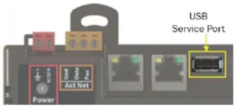
To access the controller setup pages and use the Local Network tab, you must first connect to and manually address one TV-UC561. For instructions on connecting, see Addressing the TV-UC561 through the Service port (page 9). Navigate to http://local.access or http://169.254.1.1 to access the pages. Then set up the address on your selected TV-UC561 on the Ports tab (page 42).
NOTE The first time you access the controller in the i-Vu® interface, after you have changed settings through the Service port, be sure to upload the changes to the system database. This will preserve those settings when you download memory or parameters to the controller.
ModStat tab
This tab provides the controller's Module Status report that gives information about the controller and network communication status. See Appendix - Module Status field descriptions (page 58).
Device tab
| BACnet Object | |
| Device Instance | Autogenerated—(Default) The Device Instance is automatically set to a number using the IP Address, Subnet information, and the Carrier vendor ID 16. |
| Assigned—Lets you enter a specific number that is unique on the BACnet network. | |
| Device Name | Autogenerated—(Default) The Device Name is automatically set as the word device + the Device Instance. For example, device2423911. |
| Assigned—Lets you enter a specific name that is unique on the BACnet network. | |
| Device Location | You can enter an intuitive location for the device in the i-Vu® interface. |
| Device Description | You can enter an intuitive description for the device in the i-Vu® interface. |
| Configuration | |
| APDU Timeout | How many milliseconds the device waits before resending a message if no response is received. |
| APDU Segment Timeout | How many milliseconds the device waits before resending a message segment if no response is received. |
| APDU Retries | The number of times the device resends a message. |
| Network Time Protocol | |
| To define an NTP server to use for time synchronization: | |
| 1 Click Enable. | |
| 2 Define NTP Server by one of the following: | |
| ○ IP Address | |
| ○ Host name | |
| ○ Fully qualified domain name | |
| 3 Click Save. | |
| Controller Information | |
| Clear Counts/Logs | Clears Reset counters and the three message history fields from the Module Status. |
| Data Backup and Restore | |
| Backup | Displays time of the last backup. Click button to backup the controller's control programs, properties, and schedules. |
| Restore | Displays time of the last restore. Click button to restore the most recent backup of the controller's control programs, properties, and schedules. |
| Network Factory Defaults | |
| Reset | Resets the controller to network factory default settings. |
Ports tab
| IP Port | |
| IP Addressing | Select the type of addressing the controller is to use. See Addressing the TV-UC561 (page 9). |
| Ethernet Port | |
| Address | A factory assigned Ethernet MAC Address for the Eth0 and Eth1 ports. |
BACnet tab
NOTE The TV-UC561 can be configured for only one BACnet communication type.
On the BACnet tab, you can choose to run BACnet Over IP or BACnet Over Ethernet on the Eth0 and Eth1 ports. If you choose BACnet Over IP, you can edit the BACnet UDP Port.
Security tab
| BACnet Firewall | If your BACnet Firewall configuration in the i-Vu® interface did not include the i-Vu® server IP address, thus blocking communication with the i-Vu® server, you can disable the controller’s BACnet Firewall on the controller setupSecurity tab. |
| NOTE You can enable the BACnet Firewall only in the i-Vu® interface. |
Local Network tab
Use the Local Network tab to:
- Discover 256 i-Vu® XT or TruVu™ devices on a single network at a time.
• Discover both configured or unconfigured devices on this controller's network.
• See the number of devices discovered and the total number on the network. - Identify the i-Vu® XT or TruVu™ controller that has had its DSC button pressed.
- Export the Local Devices that are present in the table (limited to 256) to a .csv file.
- Set a device's Mode, Address, and Location.
- Assign IP addresses to multiple devices at one time.
- Prompt an LED to blink on a device.
A device that is new from the factory or has not been previously configured with an IP address, can always be configured using the Local Devices table. However, once you have assigned a valid IP address, you have up to 24 hours to make any other changes. After 24 hours, the fields are not editable and the device is Locked.
You can unlock a device for 24 hours by either pressing the DSC button on the TV-UC561 controller or by using the i-Vu® application. In the i-Vu® navigation tree, right-click the TV-UC561, select Driver Properties and go to Driver > Settings tab > Local Network Configuration. Check Allow Local Network Configuration from other devices on the local network for 24 hours and click Accept.
Local Network Configuration
√ Allow Local Network Configuration from other devices on the local network for 24 hours
To discover devices on a network
1 To address a network of devices, you must first select one i-Vu® XT or TruVu™ controller and set the IP Address, Subnet Mask, and Default Gateway on the Ports tab.
NOTE This controller is referred to as the connected controller.
2 On the Local Network tab, at the top of the page, verify that the connected controller's Mode, IP Address, Subnet Mask, and Default Gateway are accurate.
3 Use the following settings to define the devices that you want to discover in the Local Devices table.
| Local Devices | |
| Only Unconfigured | When checked, only discovers devices that do not have an IP address and are linked to the connected controller's network.When unchecked, discovers both configured and unconfigured devices. |
| Clear All | Erases all information in the table. |
| Export | Creates .csv file of the data in the table, limited to 256 devices. |
4 Click Discover to populate the table with your i-Vu® XT or TruVu™ devices that are on a single network communicating with the connected i-Vu® XT or TruVu™ controller.
To auto-assign IP addresses to multiple devices at one time
1 Follow the above steps to Discover devices.
2 In the Select column, click the checkbox for the devices you want to assign addresses to.
NOTE To change the IP Address, the device's Mode must be Custom Static.
3 Enter the starting IP address under Address and click Assign to automatically assign sequential IP addresses.
There are different workflows for using the Local Devices table to address your devices, depending on the information you have from the installation. See To address when you know the serial numbers (page 12) or To address when you do not know the serial numbers (page 13).
| Local Devices table | |
| Select | Check to select devices for:Changing the ModeResolving a MismatchAuto-assigning an IP AddressNOTE You cannot select devices with a lock symbol. |
| MAC | Ethernet MAC address of device |
| Serial# | The discovered devices are in order by serial number.NOTE To change how the rows are sorted, click a different column heading. |
| Mode | To change the Mode:1 Select the devices you want to change.2 Select one of the following IP addressing modes:Default IP - Devices with rotary switches that are used when autogenerating the address (if applicable)Custom Static - A permanent IP addresses which does not change and is usually obtained from the network administratorNOTE Selecting this automatically sets the device's subnet and default gateway to match the connected controller.DHCP - Allows the DHCP server to automatically assign an IP address3 Click the Set button. |
| Address | Displays the IP address of the device, if assigned. You can edit the address only if the device is set to Custom Static.To auto-assign multiple sequential addresses, select the devices, enter the beginning address, and click Assign. |
| Location | You can describe the location of the device or any other helpful information. |
| Mismatch | A Mismatch occurs when the connected controller's mode is set to Custom Static and a discovered device's subnet and default gateway do not match the connected controller. The incorrect addresses are shown with SN for subnet and GW for default gateway.To resolve a mismatch, select the device(s) by clicking the Select checkbox and then clicking the Resolve button. The subnet mask and default gateway addresses of the selected devices change to match the connected controller. |
| Status | The following are the results of changing Mode, Address, Location, or pressing Blink:Success - Successful operationNo Response - Device is not communicatingDevice Locked - Device must be unlocked before you can make any changes using the Local Devices table. You can unlock the TV-UC561 by pressing the DSC button on the device or by using the i-Vu® application.(See instructions above.)NOTE The status of a device changes to locked 24 hours after unlocking it.Failure - A conflict between the device and the information entered |
| Blue dot | A blue dot appears for the most recent device to have the:Blinkbutton clicked in the tableAddressor LocationenteredDSC button pressed on the deviceNOTEIf the device is not already listed in the table, pressing the DSC button immediately adds it to the table and displays a blue dot.TIPYou can build a table of devices in the order that you’ve pressed the DSC buttons. Clear the table and then press each DSC button in turn. The devices will be listed in the table in the order in which the button was pressed, but only the most recent one will show the blue dot. |
| Blink | Click theBlinkbutton to prompt the Locator LED to flash for 15 seconds, allowing you to verify the controller's physical location. After flashing, whenever the actuator moves, the LED rotates in the same direction. LED rotation is automatically disabled after 1 hour and can be re-enabled by pressing theBlinkbutton again.At the same time, theSysandNetLEDs blink white, once per second for 10 seconds, and then stop.NOTESThe blue dot appears when youBlinka device.You canBlinka locked device. |
NOTE If a device's IP address is the loopback address (127.0.0.1), it is considered unconfigured and unlocked. The IP address, subnet mask, and default gateway fields are blank in the Ports and Local Network tabs. You can configure it in the Local Devices table.
To communicate through the BACnet/Service port network
You can connect to the Service port to access your network through the i-Vu® application.
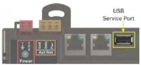
See Addressing the TV-UC561 through the Service port (page 9) to set up your connection to the web browser if you haven't already.
1 Open a web browser on the computer and launch your i-Vu® application.
2 In the i-Vu® interface, on the System Options tree, select Connections.
3 On the Properties page > Configure tab, select BACnet/IP Service Port Connection from the drop-down list and click Add.
4 If needed, enter the Service Port Network Number as follows:
- 0 - the TV-UC561 will communicate only with the computer or TruVu™ ET Display
- 1 to 65534 - the TV-UC561's network number for network communication
65535 - searches for an available network number from 65531 to 65534. If any of these numbers are not available, you will have to assign a network number and enter it.
5 Click Apply.
6 On the right of the page, in the Networks using selected connection table, click the checkbox next to the network you want to connect to.
7 Click the Start button. The status changes to Connected.
NOTE If an error message appears, make sure the COM port you selected is not in use. For example, PuTTY may be open and holding the port open.
8 Click Accept.
9 Open a web browser on the computer and login to your i-Vu® Pro application.
10 In the i-Vu® Pro interface, on the System Options tree, select Connections.
11 On the Properties page > Configure tab, Select BACnet/IP Service Port Connection from the drop-down list and click Add.
12 If needed, enter the Service Port Network Number as follows:
- 0 - the TV-UC561 will communicate only with the computer or TruVu™ ET Display
- 1 to 65534 - the TV-UC561's network number for network communication
65535 - searches for an available network number from 65531 to 65534. If any of these numbers are not available, you will have to assign a network number and enter it.
13 Click Apply.
14 On the right of the page, in the Networks using selected connection table, click the checkbox next to the network you want to connect to.
15 Click Apply.
16 Select the BACnet/IP Service Port Connection and click Start. The status changes to Connected.
17 Click Accept.
18 On the navigation tree, right-click the controller that you are connected to and select Module Status. If a Modstat report appears, the i-Vu® application is communicating with the controller.
To communicate locally through the Rnet port
You can connect a computer running Field Assistant to the TV-UC561's Rnet port to download or troubleshoot.
PREREQUISITES
• A computer with a USB port
• A USB Link (Part #USB-L)
- For the Field Assistant application to communicate with the controller, the controller must have been downloaded with at least its driver.
• A 3-pin screw terminal connector and 3-wire cable

CAUTIONS
- Maintain polarity when controllers share power.
- Failure to maintain polarity while using the USB Link on a computer that is grounded via its AC adapter may damage the USB Link and the controller.
- If multiple controllers share power but polarity was not maintained when they were wired, the difference between the controller's ground and the computer's AC power ground could damage the USB Link and the controller. If you are not sure of the wiring polarity, use a USB isolator between the computer and the USB Link. Purchase a USB isolator online from a third-party manufacturer. Plug the isolator into your computer's USB port, and then plug the USB Link cable into the isolator.
1 The USB Link driver is installed with a v6.5 or later system. Please refer to the Silicon Labs website and search "CP210x USB to UART Bridge VCP Drivers" for the most current device drivers. Install the driver before you connect the USB Link to your computer.
2 Connect one end of a piece of 3-wire cable to the 3-pin connector.
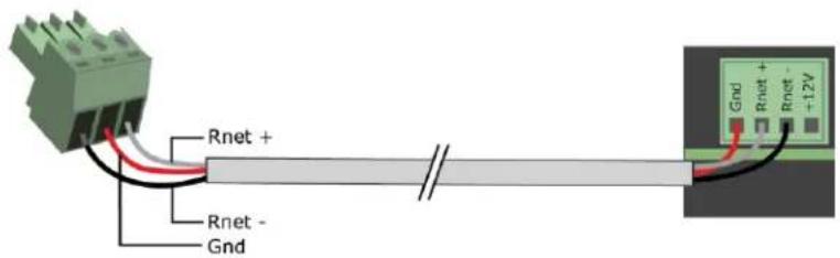
3 Connect the other end of the 3-wire cable to the TV-UC561's Rnet port as shown in the drawing above in step 1.
4 Connect the 3-pin connector to the portion of the USB link kit shown in the drawing below, then connect the USB connector to the computer.
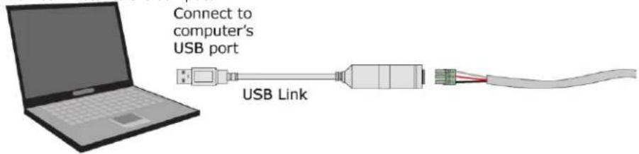
To set up a Local Access connection in the i-Vu® interface
For the i-Vu® Pro application to communicate with the Rnet port, you must do the following:
1 Click , select System Options > Connections.
2 On the Configure tab, click Add.
3 From the Type drop-down list, select BACnet/Rnet Connection.
4 Optional: Edit the Description.
5 Type the computer's Port number that the USB cable is connected to.
NOTE To find the port number, plug the USB cable into the computer's USB port, then select Start > Control Panel > System > Device Manager > Ports (Com & LPT). The COM port number is beside Silicon Labs CP210x USB to UART Bridge.
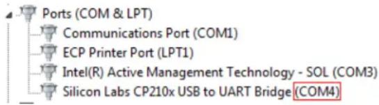
6 Set the Baud rate to 115200.
7 Click Apply.
8 On the right of the page, in the Networks using selected connection table, click the checkbox next to the network you want to connect to.
9 Click Apply.
10 Select BACnet/Rnet Connection, then click Start.
NOTE If an error message appears, make sure the COM port you selected is not in use. For example, PuTTY may be open and is holding the port open.
11 Click Close.
12 On the navigation tree, select the controller that you are connected to.
13 Click Select Manual Command.
14 Type rnet here in the dialog box, then click OK.
15 On the Properties page, click Module Status. If a Modstat report appears, the i-Vu® application is communicating with the controller.
Troubleshooting
LEDs
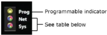
Net (Network Status) Tricolor LED
| Color | Pattern | Condition | Message in Module Status | Possible Solutions |
| Red | On | Ethernet connection problem | No Ethernet Link | Connect Ethernet CableCheck other network components |
| Red | 1 blink | One of the following BACnet/IP (Ethernet) DLL reporting issue:Unable to create tasksUnable to open socket for BACnet port | BACnet/IP error | Cycle power |
| Blue | On | One of the following issues:Port communication firmware did not load properlyPort communication firmware is not runningInvalid protocol selected | MSTP firmware error | Change protocol using USB Service PortCycle power |
| Blue | 1 blink | Invalid address selected for protocol | Invalid address selection for MSTP | Change MAC address to unique address using USB Service Port |
| Blue | 2 blink | Controller has same MAC address as another connected device | Duplicate address on MSTP | Change MAC address to a unique value using USB Service Port to valid address |
| Blue | 3 blink | Controller is the only device on the network | No other devices detected on MSTP | Check that network cable is connected properlyCheck that baud rate is correct |
| Blue | 4 blink | Excessive errors detected over 3 second period | Excessive communication errors on MSTP | Check that network cable is connected properlyCheck that baud rate is correct |
| Green | On | All enabled networks are functioning properly | No errors | No action required |
| Color | Pattern | Condition | Message In Module Status | Possible Solutions |
| Magenta | Operating system changes are downloadingWARNING This process could take several minutes. Do NOT power off the controller during the download. | N/A | No action required | |
| White | 1 blink every second for 15 seconds | The Blink button on the controller setup Local Network tab has been pressed | N/A | No action required |
Sys (System Status) Tricolor LED
| Color | Pattern | Condition | Message in Module Status | Possible Solution |
| Red | 2 blink | Restarting after an abnormal exit | Auto restart delay due to system error on startup | After 5 minute delay has expired, if condition occurs again then cycle power |
| Red | 4 blink | Firmware image is corrupt | Firmware error | Download driver again |
| Red | Fast blink | Firmware error has caused the firmware to exit and restart | Fatal error detected | No action required |
| Green | 1 blink | No errors | Operational | No action required |
| Green | 2 blink | Download of driver is in progress | Download in progress | No action required |
| Green | 3 blink | BACnet Device ID is not set | Download required | Download the controller |
| Green | Fast blink | Installation of recently downloaded driver is occurring | N/A | No action required |
| Blue | On | Controller is starting up | N/A | No action required |
| Blue | Slow blink | Linux (operating system) is starting up | N/A | No action required |
| Blue | Fast blink | Linux is running but it could not start the firmware application | N/A | Download driver |
| Magenta | Operating system changes are downloadingWARNING This process could take several minutes. Do NOT power off the controller during the download. | N/A | No action required | |
| White | 1 blink every second for 15 seconds | The Blink button on the controller setup Local Network tab has been pressed | N/A | No action required |
To configure custom Prog LED
You can customize the Prog LED for site-specific purposes by configuring the BACnet Analog Output (BAO) microblock.
Open your control program in the Snap interface, select the AO microblock for the LED, and use the following settings:
| Status/Attribute | Microblock type | Expander number : Channel number | I/O type | Description |
| LED | BAO | 0:61 | Special | <=0 Normal>15 OnThe number of blinks equals the Present Value.The pulse pattern repeats after a 2-second delayLED will blink the number of times given in the BAO with ON pulse 0.5 seconds and OFF pulse 0.5 seconds. |
To get a Module Status report
A Module Status report provides information about the controller and verifies proper network communication with the controller. You can get this report:
- In the i-Vu® application—Right-click the controller on the navigation tree, then select Module Status.
- In the Field Assistant application—Right-click the controller in the navigation tree and select Module Status.
- On the controller setup ModStat tab—See To set up the controller through the Service Port (page 40).
See Module Status field descriptions (page 58) in the Appendix.
Troubleshooting inputs and outputs
The i-Vu® interface shows if you have I/O errors resulting from a misconfigured microblock.
To check for errors:
1 In the i-Vu® navigation tree, select the equipment controlled by the TV-UC561.
2 On the Properties page, select the I/O Points tab.
3 Click the Name of any input or output whose name is red (indicates an error) to open its dialog box.
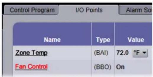
4 On the Details tab, scroll down to see the Reliability field under BACnet Configuration.
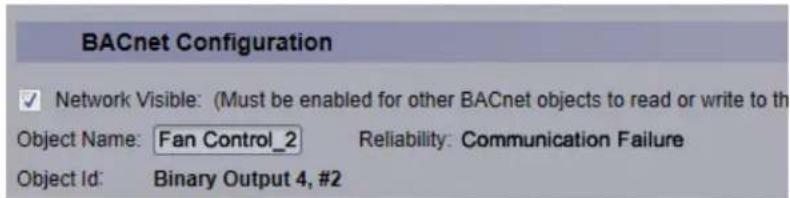
5 Anything other than No Fault Detected indicates an error. See the table below to determine the error and possible actions to take.
| Reliability description | Possible error | Verify that... |
| Configuration Error | The microblock's I/O Type and Sensor/Actuator Type are not compatible.The output's DIP switch setting does not match the connected device.Invalid expander address or I/O number. | The I/O Type and Sensor/Actuator Type combination is valid for the I/O number and microblock type.The DIP switch setting is appropriate for the output and microblock type.The expander is present and functional at the address shown in the i-Vu® interface and that I/O number is valid. |
| Over Range | Input exceeds the Min/Max limits. | The input is within the Min/Max limits. |
| No Sensor | No device is attached to the output. | The device is present and functioning. |
| Shorted Loop | Internal voltage feedback does not correspond with commanded value. | The load on the output is within the valid range.A voltage/current source has not been connected to an output. |
| Open Loop | Internal current feedback does not correspond with commanded value. | The load on the output is within the valid range.A voltage/current source has not been connected to an output. |
| Unreliable Other | Feedback does not correspond with commanded value (for example, the output relay is not in commanded state). | Device may be faulty. Contact Carrier Control Systems Support. |
To get a Device Log
If Carrier Control Systems Support instructs you to get the controller's Device Log containing diagnostic information for troubleshooting:
1 Select the TV-UC561 in the i-Vu® navigation tree.
2 On the Properties page, click Device Log.
NOTE You can click Device Log Archive to download a file containing multiple Device Logs to your computer. This also contains any network packet captures that have been run from the Network Diagnostics - Packet Captures (page 35) driver page.
To get the TV-UC561's serial number
If you need the controller's serial number when troubleshooting, the number is on:
• A Module Status report (Modstat) under Core (or Main) board hardware

• A QR code, serial number, and MAC address printed on a sticker on the cover
- A laser-etched number and QR code on the inside circuit board.
See To get a Module Status report (page 52).
To replace the TV-UC561's fuse
The TV-UC561 has one fuse.
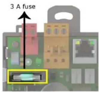
If the TV-UC561's power LED is not lit, this could be due to a blown power fuse.
If you suspect a fuse is blown, remove the fuse as described below, and use a multimeter to check it. If the fuse is blown, try to determine why it blew before you replace it. Check the power wiring polarity of the TV-UC561 and any other devices that share the power supply. Use the same polarity for all of them.
You can purchase the 3 A, fast-acting, 5mm x 20mm glass fuse from Littelfuse, mfr part #0235003.HXP.
To replace the fuse:
1 Remove the red power connector.
2 On both ends of the TV-UC561, insert a small flathead screwdriver as shown below, and then gently pry up the cover until it is released from the base.
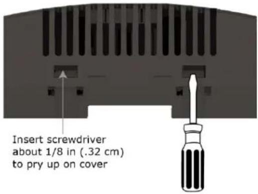
3 Remove the cover from the base.
4 Remove the blown fuse.
5 Snap the new fuse into the fuse holder.
6 Replace the TV-UC561's cover.
7 Replace the power connector.
8 Verify the LEDs on the TV-UC561 are lit.
To revert to default settings

WARNING This erases all archived information and user-configuration settings. When recovery is complete,
you have to reconfigure all custom settings. You must connect locally to the TV-UC561 and manually reconfigure all the communications and firewall information. We highly recommend that you revert the defaults settings only under the guidance of Carrier Control Systems Support.
To erase volatile memory data and restore factory default configuration settings, use AppLoader to download the appropriate clipping.
See the AppLoader User Guide for details.
To take the TV-UC561 out of service
If needed for troubleshooting or start-up, you can prevent the i-Vu® application from communicating with the TV-UC561 by shutting down communication from the TV-UC561 to the i-Vu® application. When Out of Service, i-Vu® no longer communicates properties, colors, trends, etc.
1 On the i-Vu® navigation tree, select the TV-UC561.
2 On the Properties page, check Out of Service.
3 Click Accept.
Compliance
FCC Compliance
This device complies with Part 15 of the FCC Rules. Operation is subject to the following two conditions:
1 This device may not cause harmful interference.
2 This device must accept any interference received, including interference that may cause undesired operation.
NOTE This equipment has been tested and found to comply with the limits for a Class A digital device, pursuant to Part 15 of the FCC Rules. These limits are designed to provide reasonable protection against harmful interference when the equipment is operated in a commercial environment. This equipment generates, uses, and can radiate radio frequency energy, and if it is not installed and used in accordance with this document, it may cause harmful interference to radio communications. Operation of this equipment in a residential area is likely to cause harmful interference, in which case the user will be required to correct the interference at his own expense.

CAUTION Any modifications made to this device that are not approved by Carrier will void the authority ed to the user by the FCC to operate this equipment.
CE and UKCA Compliance

WARNING This is a Class B product. In a light industrial environment, this product may cause radioference in which case the user may be required to take adequate measures.
Industry Canada Compliance
This Class A digital apparatus complies with Canadian ICES-003.
Compliance of listed products to requirements of ASHRAE Standard 135 is the responsibility of BACnet International. BTL ^® is a registered trademark of BACnet International.
Appendix - Module Status field descriptions
| Field | Description |
| ADDRESS BINDING | The controller's:Device InstanceNetwork numberMAC addressSee To set up the controller through the Comm/Service ports (page 40). |
| Date/Time | Date and time the Modstat was run |
| Model Name | Identifies the Product Type |
| Device Instance | A unique ID assigned to the controller |
| Driver built | When the driver was built |
| Downloaded by | When and where the last download was performed |
| Application Software Version | The name of the first control program that is downloaded |
| Data Partition Version | Not applicable to this device. |
| # PRGs initialized# PRGs running | If applicable, the number of control programs that were downloaded vs. the number that are running. If these numbers are not the same, the controller has a problem such as lack of memory. |
| Driver version | The name, version, and date of the driver, as well as all the bundles and versions. |
| Reset Counters: | The number of times each of the following events have occurred since the last time the controller was commanded to clear the reset counters.See NOTE below this table. |
| Power failures | Interruption of incoming power |
| Commanded boots | Includes commands issued from the i-Vu® interface such as the zap manual command, plus commands issued during a memory download. |
| System errors | Error in the controller's firmware or hardware |
| S/W Watchdog timeouts | Watchdog is firmware that monitors the application firmware for normal operation. If the watchdog firmware detects a problem, it restarts the application firmware. |
| H/W Watchdog timeouts | H/W Watchdog will restart the controller if it detects a severe problem with the controller's operating system |
| System status | Gives the current status of the controller's operation. See LEDs (page 50) for all possible conditions. |
| Network status | Gives the current status of the controller's networks. See LEDs (page 50) for all possible conditions. |
| System error message history | High-severity errors since the last memory download. Shows the most recent 10 messages.See NOTE below this table. |
| Warning message history | Low-severity errors and warning messages since the last memory download. Shows the most recent 10 messages.SeeNOTEbelow this table. |
| Information message history | Information-only messages since the last memory download. Shows the most recent 10 messages.SeeNOTEbelow this table. |
| Core and Base board hardware | Gives the following information about the controller's boards:Type and board numbers that are used internally by Carrier.The manufacture date and serial number. |
| Number of BACnet Objects | The number of BACnet objects that were created in the device and the number of those objects that are network visible. |
| Database Partition | Non-Volatilepartition (16 MB maximum) contains data that needs to be preserved through a power cycle and archived to flash such as parameters and trend data.Volatilepartition (6 MB maximum) contains data that does not need to be preserved through a power cycle such as status values that are calculated during runtime. |
| IP Networks - BBMDs | Shows the following information for each active IP network:BBMD Activeshows whether the BACnet Broadcast Management Device is currently active (1) or inactive (0).BBMD Entries—the number of entries in the BBMD table (500 maximum).FDT Entries—the number of entries in the Foreign Device Table (500 maximum). |
| Network Information | The various network addresses for the controller. TheCurrentand Assignedaddresses will be the same unless theEnable IP configuration changeoveron theBACnet Router Propertiespage is being implemented. |
| Statistics and Network Activity | Shows network communication statistics to assist with troubleshooting. See Network Diagnostics - Statistics (page 34) for more information. |
NOTE If you want to clear the Reset counters and the three message history fields, click the Clear Counts/Logs button on the controller's Properties page in the i-Vu® application or in the controller setup Device tab.
Document revision history
Important changes to this document are listed below. Minor changes such as typographical or formatting errors are not listed.
| Date | Topic | Change description | Code* |
| 7/17/23 | Driver | Added Disable Eth1 Port | X-TS-RB-R-RB |
| Device tab | Added Network Time Protocol and Network Factory Defaults rows | X-D-TG | |
| Specifications | Added Australia and New Zealand to Compliance | X-PM-JW-R-BH | |
| 10/24/22 | Zone Sensors | Changed Rnet power specification from 210mA to 260mA | X-PM-DD-E |
| 5/10/22 | CE and UKCA Compliance | Added UKCA Compliance | X-PM-AB-R-BH |
| Specifications | |||
| Addressing the TV-UC561 through the Service port | Added Caution regarding USB connection | X-PM-BM-R-BM | |
| Inputs | Updated pulse counting note | X-TS-RB-R-RB | |
| Input values | Updated Pulse to Analog information | ||
| Specifications | Added Aux 24v+ DC | X-PM-BM-R | |
| 1/26/22 | Specifications | Updated EU Compliance | X-PM-BM-E |
| 12/2/21 | Specifications | Removed reference to not change position of power switch | X-PM-BM-O |
| To set the IP address | Removed Sitebuilder reference | C-TS-BB-O | |
| To communicate through the BACnet Service Port network > Wiring specifications | Changed warning for minimum bend radius | X-TS-BB-O-BM | |
| Wiring devices to the TV-UC561 Rnet Port | Changed Rnet rate of communication from 115 kbps to 115.2 kbps | X-TS-BB-O | |
| Specifications | Specified "N.O." binary outputs | ||
| 9/16/21 | Wiring devices to the TV-UC561's Act Net port | Rephrased Act Net addresses to list fixed addresses. | X-PM-BM-E |
| What is the i-Vu® XT or TruVuTMTV-UC561? | |||
| Specifications | Changed Real time clock specification to "up to 3 days" from "at least 3 days". Changed EU RoHS compliance code. Rephrased Act Net addresses to list fixed addresses. | X-PM-BM-O |
* For internal use only

Carrier ©2023 · Catalog No. 11-808-853-01 · 7/17/2023
- Installation and Start-up Guide
- Carrier
- Contents
- What is the TV-UC561?
- Specifications
- Zone sensors
- NOTES
- CAUTION Rnet power
- Touchscreen devices
- Rnet port
- USB port
- To mount the TV-UC561
- DIN rail mount
- Screw Mount
- Wiring for power
- CAUTIONS
- To wire for power
- Addressing the TV-UC561 through the Service port
- To connect the TV-UC561 to a computer using the Carrier wireless service adapter:
- To connect the TV-UC561 to the computer using a USB cable.
- To set the IP address
- To set a DHCP IP address
- To set a custom static IP address
- Addressing a network of controllers using the controller setup Local Network tab
- Method 1: To address when you know the serial numbers
- Method 2: To address when you do not know the serial numbers
- Wiring for communications
- Wiring specifications
- WARNINGS
- To connect the TV-UC561 to the Ethernet
- Wiring devices to the TV-UC561's Rnet port
- Wiring devices to the TV-UC561's Act Net port
- Wiring inputs and outputs
- Inputs
- Outputs
- Analog outputs
- Binary outputs
- Universal output
- Output wiring
- To wire inputs and outputs
- ERNINGS
- To adjust input and output properties
- Output values
- Resolution values
- Offset/Polarity values
- Find and upload in the i-Vu® interface
- Adjusting the TV-UC561 driver properties
- Driver
- Device
- Notification Classes
- Calendars
- Common Alarms
- Common alarms:
- Specific Events
- Specific alarms:
- Custom Translation Tables
- BACnet Controller Properties
- BACnet Firewall
- Network Diagnostics - Statistics
- Network Diagnostics - Packet Capture
- To download the capture file
- Act Net Bus
- Act Net Bus Status
- To resolve duplicate addresses on Act Net bus
- Communication Status
- Standalone Controller Detection
- Flow Calibration Archive
- To set up Network Statistic trends
- You can define:
- To set up the controller through the Service port
- ModStat tab
- Ports tab
- BACnet tab
- Security tab
- Local Network tab
- Local Network Configuration
- To discover devices on a network
- To auto-assign IP addresses to multiple devices at one time
- To communicate through the BACnet/Service port network
- To communicate locally through the Rnet port
- PREREQUISITES
- To set up a Local Access connection in the i-Vu® interface
- Troubleshooting
- LEDs
- To configure custom Prog LED
- To get a Module Status report
- Troubleshooting inputs and outputs
- To get a Device Log
- To get the TV-UC561's serial number
- To replace the TV-UC561's fuse
- To revert to default settings
- To take the TV-UC561 out of service
- Compliance
- FCC Compliance
- CE and UKCA Compliance
- Industry Canada Compliance
- Document revision history
Brand : CARRIER
Model : TruVu TV-UC561
Category : Régulateur