
Sonamp DSP 8-130 MKIII - Receiver SONANCE - Free user manual and instructions
Find the device manual for free Sonamp DSP 8-130 MKIII SONANCE in PDF.


| Product Type | Multi-channel DSP Receiver / Amplifier |
| Brand | Sonance |
| Model | Sonamp DSP 8-130 MKIII |
| Number of Channels | 8 |
| Power Output (per channel) | 130W RMS at 8 ohms |
| Total Power Output | 1040W RMS |
| Frequency Response | 20 Hz – 20 kHz ±0.5 dB |
| Signal-to-Noise Ratio | >100 dB (A-weighted) |
| Total Harmonic Distortion (THD) | <0.05% |
| DSP Processing | Built-in, programmable presets |
| Inputs | 8 balanced line-level (RCA or Phoenix), 1 unbalanced (RCA), Ethernet, IR, 12V trigger |
| Outputs | 8 speaker outputs (binding posts), 1 line-level subwoofer output |
| Control Interfaces | Ethernet, serial RS-232, IR, 12V trigger, front panel |
| Rack Mountable | Yes, 2U height |
| Dimensions (W x H x D) | 17.2 in x 3.5 in x 17.2 in (437 mm x 89 mm x 437 mm) |
| Weight | 37 lb (16.8 kg) |
| Power Supply | AC 100-240V, 50-60 Hz, 1000W max |
| Operating Temperature | 32°F to 104°F (0°C to 40°C) |
| Certifications | UL, CE, FCC, RoHS |
| Warranty | 5 years (limited) |
| Maintenance & Cleaning | Use a soft dry cloth; do not use liquids or cleaners. Ensure vents are free of dust. |
| Safety Precautions | Do not operate near water. Provide adequate ventilation. Use grounded outlet. Disconnect power before cleaning. |
| Spare Parts & Repairability | Contact Sonance authorized service. Only use factory-specified parts. |
| General Information | Professional-grade multi-zone amplifier with integrated DSP for custom audio installations. |
Frequently Asked Questions - Sonamp DSP 8-130 MKIII SONANCE
User questions about Sonamp DSP 8-130 MKIII SONANCE
0 question about this device. Answer the ones you know or ask your own.
Ask a new question about this device
Download the instructions for your Receiver in PDF format for free! Find your manual Sonamp DSP 8-130 MKIII - SONANCE and take your electronic device back in hand. On this page are published all the documents necessary for the use of your device. Sonamp DSP 8-130 MKIII by SONANCE.
USER MANUAL Sonamp DSP 8-130 MKIII SONANCE
INSTALLATION AND SUPPORT MANUAL
MULTI-CHANNEL POWER AMPLIFIER
DSP 8-130 MKIII AMPLIFIER

FRONT VIEW

BACK VIEW
TABLE OF CONTENTS
2 Box Contents
2 Introduction
2 Important Safety Information
3 Product Description
3 Placement
3 Unpacking and Record Keeping
4 Front and Rear Panel Features
5 Power the Amplifier
6 Speaker Connections
6 Bridging Channels
7 Volume Level Control
7 Protecting Circuitry, LEDs, and Speakers
8 Rack Ear Installation
8 Amplifier Stacking
8 Sonarc SetUp
15 Specifications
16 Appendix A and B
17 Troubleshooting
19 Warranty Statement
BOX CONTENTS
(1) Quickstart Guide
(1) Network Connection Instructions
(1) Sonance DSP 8-130 MKIII Amplifier
(1) IEC Power Cord
(4) Removable Amp Feet
(2) Rack Ears
INTRODUCTION
Thank you for selecting the Sonance DSP 8-130 MKIII amplifier. Sonance has over three decades of experience in premium distributed audio amplification. The amplifier has been precision engineered to provide maximum installation flexibility, low energy consumption and audiophile sound in a compact form factor (IRU). Please take the time to carefully read through the manual, study the illustrations and system diagrams. This extra time can lead to trouble free operation and continued musical enjoyment.
READ THIS SECTION IN ITS ENTIRETY BEFORE ATTEMPTING USE OF THIS AMPLIFIER
IMPORTANT SAFETY INSTRUCTIONS ALWAYS FOLLOW THESE BASIC SAFETY PRECAUTIONS WHEN USING YOUR AMP TO REDUCE THE RISK OF FIRE, ELECTRIC SHOCK, AND INJURY TO PEOPLE OR OBJECTS.
- Read all the safety and operating instructions before operating the amplifier and retain them for future reference.
- Adhere to all warnings and precautions listed on the amplifier and in the operating instructions.
- Follow all operating instructions.
- Never use the amplifier next to water.
- Use only with a cart or stand that is recommended by the manufacturer. Move with care.
- Ventilation: situate the amplifier so that its location does not interfere with its proper ventilation.
- Heat: situate the amplifier away from heat sources such as radiators, stoves, etc. (including amplifiers).
- Grounding or Polarization: take precautions so that these attributes are not defeated.
- Power-Cord Protection: route power supply cords so they will not be walked on or pinched by items.
- Cleaning: use 'canned air' or wipe the amplifier with a soft cloth. Do not use solvents, as they may damage the amplifier.
- Non-Use Periods: unplug the amplifier's power cord from the outlet when the amplifier will be left unused for a long period of time.
- Object Entry: take care so that objects do not fall through the opening of the enclosure.
- Moisture: do not expose the amplifier to dripping or splashing. Do not place objects filled with liquids (ex. vases, drinking glasses) on the amplifier.
6. CAUTION: TO PREVENT ELECTRIC SHOCK, DO NOT USE THE POLARIZED PLUG WITH AN EXTENSION CORD, RECEPTACLE, OR OTHER OUTLETS UNLESS THE BLADES CAN BE FULLY INSERTED TO PREVENT BLADE EXPOSURE.
- Damage Requiring Service: have the amplifier serviced by a qualified service technician when the power cord or power supply is damaged, dropped, the enclosure is damaged, something has spilled into the amplifier, it has been exposed to rain, or the amplifier is not operating properly.
- Servicing: do not attempt to self service the amplifier. Contact Sonance Tech Support for servicing options.
- Power Requirement: do not connect the Sonance amplifier to the accessory outlet of any other component. Connection to a grounded mains power outlet is required.
WARNING: THE POWER MAINS PLUG SERVES AS THE AMPLIFIER'S DISCONNECT DEVICE. THE DISCONNECT DEVICE SHALL REMAIN READILY OPERABLE DURING OPERATION. TO ENSURE THAT THE DISCONNECT DEVICE IS EASILY ACCESSIBLE, THE USER SHALL NOT PLACE THE AMPLIFIER IN A CONFINED AREA DURING OPERATION.
-
Storms: to prevent damage to components, unplug all electronic equipment during thunderstorms.
-
Unplug by grasping the plug; do not pull on the cord.
WARNING: ANY CHANGES OR MODIFICATIONS TO THIS UNIT NOT EXPRESSLY APPROVED BY THE PARTY RESPONSIBLE FOR COMPLIANCE COULD VOID THE USER'S AUTHORITY TO OPERATE THE EQUIPMENT.
NOTE: THIS EQUIPMENT HAS BEEN TESTED AND FOUND TO COMPLY WITH THE LIMITS FOR A CLASS B DIGITAL DEVICE, PURSUANT TO PART 15 OF THE FCC RULES. THESE LIMITS ARE DESIGNED TO PROVIDE REASONABLE PROTECTION AGAINST HARMFUL INTERFERENCE IN A RESIDENTIAL INSTALLATION. THIS EQUIPMENT GENERATES, USES, AND CAN RADIATE RADIO FREQUENCY ENERGY AND IF NOT INSTALLED AND USED IN ACCORDANCE WITH THE INSTRUCTIONS, MAY CAUSE HARMFUL INTERFERENCE TO RADIO COMMUNICATIONS. THERE IS NO GUARANTEE THAT INTERFERENCE WILL NOT OCCUR IN A PARTICULAR INSTALLATION. IF THIS EQUIPMENT DOES CAUSE HARMFUL INTERFERENCE TO RADIO OR TELEVISION RECEPTION, WHICH CAN BE DETERMINED BY TURNING THE EQUIPMENT OFF AND ON, THE USER IS ENCOURAGED TO TRY TO CORRECT THE INTERFERENCE BY ONE OR MORE OF THE FOLLOWING MEASURES:
- Connect the equipment into an outlet on a circuit different from that to which the receiver is connected
- Consult the dealer or technician for help
- Reorient or relocate the receiving antenna
- Increase distance between the equipment and receiver
PRODUCT DESCRIPTION
The DSP 8-130 MKIII combines the powerful equalization of Sonance's DSP amplifiers with unparalleled ease of use. Through the back panel preset interface, most Sonance loudspeakers can have a custom equalization curve applied. When additional customization is
required, the SonARC V2 interface can be accessed through the ethernet port.
The amplifier is rated at 150W per channel into 8 ohm loads, 245W per channel into 4 ohm loads and 475W per bridged pair of channels into 8 ohm loads. The internal stereo amplifier modules are audiophile grade, high-efficiency Class D. The amplifier is configurable for stereo (4 or 8 ohm speakers) and/or bridged operation (8 ohm speakers only). Bridged operation is useful for higher power output applications such as driving a passive subwoofer or an outdoor 8 ohm satellite and subwoofer system. Audio source connections can be made into the RCA inputs or the Coaxial or Optical Digital Inputs. The DSP 8-130 MKIII has a comprehensive protection circuit that guards against shorted outputs, over-current, over-temperature, low AC voltage (brownouts) and excessive AC voltage.
PLACEMENT
The DSP 8-130 MKIII features fan-assisted cooling utilizing vents on both sides of the chassis. Ensure the sides of the amplifier have a least 3" (75mm) of clearance to the sides of the rack or equipment cabinet to allow for proper air flow. The amplifier should be placed in a dry, non-condensing environment with ventilation. Locate the amplifier so it is completely isolated from temperature extremes, rain, snow, direct sunlight, and atmospheric contaminants. Do not locate the amplifier outdoors. Any moisture related damage (such as from condensation) is not covered by the factory warranty. The amplifier includes fan-assisted cooling, some heat is still produced. Locate the amplifier on a shelf or at the lowest place in a rack that has good circulation of fresh air to dissipate heat. Do not place the amplifier in a closed cabinet or closet with little ventilation as this can reduce its service life.
UNPACKING AND RECORD KEEPING
Save the carton and packing inserts for future safe transport in case the amplifier is moved or requires shipping for repair. Before proceeding with installation, locate the serial number on the rear panel of the unit and note it here for future reference:
S/N:
Date of Sale: ____
Dealer Name:
Contact Info:
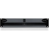
DSP 8-130 MKIII FRONT PANEL

Figure 3: DSP 8-130 MKIII Multi-Channel Power Amplifier Front Panel

Figure 4: DSP 8-130 MKIII Multi-Channel Power Amplifier Rear Panel
Front Panel
- Illuminated Power Button
- Active Audio and Protection Indicator
Rear Panel
- Analog Input/Output Module
- Reset Button
- Voltage Control and IR Control Input
- RJ-45 Input
- AC Fuse Holder
- Speaker Output
- AC Input
FRONT PANEL
POWER BUTTON
The power button turns the amplifier on and off. The Sonance logo power button has three settings:
- SOLID WHITE means the amplifier is engaged. The amplifier has power, is turned ON and ready to operate.
- SLIGHTLY DIMMED means the amplifier is in sleep mode.
- BLINKING WHITE means the power supply is in thermal protection. In this situation, the channel LEDs also illuminate red, indicating that the power supply is in thermal protection mode.
NOTE: UPON INITIAL POWER UP, THERE WILL BE A 20-30 SECOND DELAY BEFORE SOUND IS HEARD DURING THE BOOT UP CYLE. THE INDICATOR LEDS WILL ILLUMINATE RED, THEN GREEN, THEN GO OUT. THIS IS NORMAL.
INPUT/OUTPUT LIGHTS
When each channel is active:
- GREEN LED means a signal is present.
- BLINKING RED Input/Output LED indicates that the associated channel is being over-driven.
- SOLID RED Input/Output LED indicates that the amplifier is in protect mode. While in protect mode, the LEDs periodically light up green. This retests output to determine if the issue is resolved. Protect mode could be caused by a short in the wire, amplifier overheating, or other internal problem.
NOTE: WHEN ANY OF THE LEDS ARE RED, TURN THE AMPLIFIER OFF IMMEDIATELY. DETERMINE THE CAUSE OF THE PROBLEM BEFORE TURNING THE AMPLIFIER BACK ON.
CAUTION: FOR CONTINUED PROTECTION AGAINST FIRE, REPLACE THE FUSE WITH ONLY THE SAME TYPE AND RATING.
VOLUME LEVEL CONTROL
Each channel on the amplifier has volume adjustments controlled in the SonARC software or on the front panel recessed volume controls. Output volume reflects the most recently adjusted control method. The DSP 8-130 MKIII amplifier ships at the +0dB or moderate volume level.
REAR PANEL
LINE INPUTS/LOOP OUTPUTS
The DSP 8-130 MKIII amplifier has line inputs and loop outputs. The analog loop outputs are non-buffered. The maximum number of amplifiers that can be looped together depends on the output capability of your source component.
SPEAKER CONNECTIONS
The removable block connectors used on the amplifier accept up to a 12-gauge wire. Follow the connection layout on the rear panel of the amplifier. Make sure no bare wires come in contact with the amplifier chassis. When bridging channels, use the two outside connections on each connector. The positive wire from the speaker should be on the left side connection and the negative connection should be on the right side.
IP CONTROL
IP control is via the RJ-45 input. IP controls power On/Off, volume, muting, and input source selections for either global control or group control.
AC FUSE HOLDER
To replace the fuse, unplug the power cord from the Power Cord Connector and use a screwdriver to remove the fuse holder.
POWER CORD
The DSP 8-130 MKIII features a removable power cord. Plug the female end of the power cord into the Power Cord Connector on the amplifier rear panel and plug the male end into a grounded wall socket.
Do not plug the amplifier's power cord into a convenience outlet on any other audio or video component. If you need to use an extension cord, use only a heavy duty (14 gauge or larger) extension cord to avoid starving the amplifier of the current necessary for full operation.
POWERING THE AMPLIFIER
The DSP 8-130 MKIII features a removable IEC power cord (see Figure 3). A 14-gauge EIA standard 120 volt grounded power cable is included with the amplifier. Each time the amplifier's power cord is initially plugged in and the power switch is turned ON, all channel outputs are disconnected for approximately 9-12 seconds and all PROTECTION LEDs illuminate briefly while the amplifier boots up.
If the electrical service is subject to frequent sags, spikes or brownouts, a power conditioner designed for use with high fidelity equipment should be employed to protect the amplifier.
CAUTION: FOR CONTINUED PROTECTION AGAINST FIRE, REPLACE THE FUSE WITH ONLY THE SAME TYPE AND RATING.

Figure 3: IEC Power Cord Connection
IMPORTANT: DO NOT PLUG THE POWER CORD INTO THE WALL OUTLET UNTIL ALL SYSTEM CONNECTIONS HAVE BEEN MADE AND VERIFIED.
Plug the female end of the power cable into the Power Connector on the amplifier's rear panel and plug the male end directly into a grounded 15 amp or 20 amp wall outlet.
IMPORTANT: DO NOT PLUG THE AMPLIFIER'S POWER CORD INTO A CONVENIENCE OUTLET ON ANY OTHER AUDIO OR VIDEO COMPONENT.
SOURCE CONNECTIONS SELECTION
There are two options when connecting audio inputs to the DSP 8-130 MKIII amplifier (see Figure 4).
OPTION 1: PRIMARY LINE INPUTS 1-L, 1-R
Use these inputs for primary audio source.
OPTION 2: SECONDARY LINE INPUTS 2-L, 2-R
Use these inputs for a secondary audio source, paging or a doorbell.

Figure 4: DSP 8-130 MKIII Left and Right Line Inputs
AMPLIFIERS POWER REQUIREMENTS:
| MODEL INPUT VOLTAGE | OUTPUT POWER(SINEWAVE) | DRAW WATTS | 15 AMP BREAKERQTY OF AMPS | 20 AMP BREAKERQTY OF AMPS | |
| DSP 8-130 MKIIINorth AmericaSKU: 93538InternationalSKU: 93539 | 100-120V AC | Full Power All Channels @8 ohms 371 3 5 | |||
| Full Power All Channels @4 ohms 392 3 4 | |||||
| 1/8 Power All Channels @8 ohms 72 20 26 | |||||
| 1/8 Power All Channels @4 ohms 74 19 25 | |||||
| @ Idle 17 | - | - | |||
| Sleep Mode 1.5 | - | - | |||
| Voltage or Green Audio 0.48 | - | - | |||
| INPUT VOLTAGE | OUTPUT POWER(SINEWAVE) | DRAW WATTS | 13 AMP BREAKERQTY OF AMPS | 20 AMP BREAKERQTY OF AMPS | |
| 220-240V AC | Full Power All Channels @8 ohms 359 4 5 | ||||
| Full Power All Channels @4 ohms 376 3 5 | |||||
| 1/8 Power All Channels @8 ohms | 69 | 20 | 27 | ||
| 1/8 Power All Channels @4 ohms | 71 | 20 | 27 | ||
| @ Idle 15 | - | - | |||
| Sleep Mode | 1.1 | - | - | ||
| Voltage or Green Audio | 0.5 | - | - | ||
Figure 5: DSP 8-130 MKIII Multi-Channel Amplifier Power Requirements
SPEAKER CONNECTIONS
For the best sound you should use premium speaker wire that complies with fire rating codes. Be sure to check local codes governing wire that may be installed within walls or ceilings. Amplifiers are stable with any reputable brand of speaker wire or cable. The amplifier uses speaker block connectors that can accommodate up to 12 gauge wire (see Figure 6).
NOTE: ALWAYS CHECK LOCAL BUILDING CODES BEFORE INSTALLING WIRE IN WALLS OR CEILINGS.

Figure 6: Speaker Connections
BRIDGING CHANNELS
IMPORTANT: THE MINIMUM SPEAKER IMPEDANCE FOR BRIDGED OPERATION IS 8 OHMS. DO NOT OPERATE A ZONE IN THE BRIDGED MODE INTO A SPEAKER THAT IS LESS THAN 8 OHMS NOMINAL IMPEDANCE.
Use the SonARC software to Bridge Channels. On the second page in the software under IN/OUT settings, go to the output setup area to Bridge Mode and make your selections with the drop-down buttons.
- Use the left audio input when operating the amplifier's output in bridge mode (see Figure 7).
-
Select ON in the bridge mode (see Figure 7).
-
Connect the speaker's "+" lead to the left side of the connector marked "+" (see Figure 8).
- Connect the speaker's “-” lead to the right side of the connector marked “+” (see Figure 8).
- Connect the line level audio input to the left channel input on the amplifier.
| OUTPUT SETUP | 1 LEFT | 1 RIGHT | |
| Output Name | Output1L | Output1R | |
| Stereo/Mono | Stereo | Stereo | |
| DSP Preset | FLAT | FLAT | |
| Output Group | A | A | |
| Bridge Mode | Bridge OFF | Bridge OFF |
Figure 7: Bridging Channels

Figure 8: Bridging Channels
VOLUME LEVEL CONTROL
The volume controls balance the desired sound levels per channel. Volume can be controlled three different ways with SonARC V2 (see Figure 9).
-
Output Volume
-
Turn On Volume
-
Maximum Volume
Output volume ranges between -70 to 12. The volume level controls are set at +0dB by default.
| OUTPUT VOLUME | Output Volume | 0 | 0 |
| Turn On Volume | 6 | 6 | |
| Maximum Volume | 12 | 12 | |
| Gain Offset | 0 | 0 | |
| Mute | OFF | OFF |
Figure 9: SonARC Page In/Out Settings Output Volume
IMPORTANT: USE CAUTION WHEN SETTING VOLUME LEVELS EITHER ON THE AMPLIFIER OR AN AUDIO SWITCHER AS NOT TO OVERDRIVE AND POSSIBLY DAMAGE SPEAKERS. VERIFY ALL SOURCES AS OUTPUT VOLTAGE VARIES FROM DEVICE TO DEVICE.
PROTECTION CIRCUITRY AND LEDS
The amplifiers have a multi-stage protection system to prevent damage to your amplifier and speakers.
AMPLIFIER CHANNEL PROTECTION
If a channel encounters a short-circuit or extremely low impedance, the affected channel outputs automatically mute. The output of the affected channel remains muted until the fault is corrected. Only the affected channel outputs mute; all other channels continue to operate normally.
NOTE: IN BRIDGE MODE, THE PROTECTION CIRCUITRY SENSES A SHORT CIRCUIT ACROSS BOTH POSITIVE SPEAKER TERMINALS.
AMPLIFIER CHANNEL PROTECTION INDICATION
Dual-color LEDS on the front panel of the DSP 8-130 MKIII illuminate to indicate the current operating status of each amplifier channel.
- BLINKING RED indicates that the channel is being over driven.
- SOLID RED indicates that the amp is in protect mode.
While in protect mode the LED lights periodically light green to retest the output to determine if the short has been removed. Protect mode could be caused by a short in the wire, overheating of the amplifier or possibly an internal problem with the amplifier.
If the amplifier senses a very low impedance or a short on its outputs, then it mutes its output and the protection LEDs turn red. The output remains muted until the fault is cleared. Check the rear panel block connector for shorted wire strands or reduce the number of speakers connected in parallel to the amplifier outputs. Sonance amplifiers are rated for a 4 ohm load or higher, such as two pair of 8 ohm speakers.
AMPLIFIER POWER SUPPLY PROTECTION
The amplifier also has protection for the power supply. If the power supply heat sink temperature exceeds the design maximum, the protection circuit will activate, disconnecting all channel outputs. This is indicated by a blinking light on the front panel power switch.
IMPORTANT: OPERATING THE AMPLIFIER WITH ONE OR MORE CHANNELS IN PROTECT MODE FOR AN EXTENDED PERIOD OF TIME CAN DAMAGE THE AMPLIFIER.
IMPORTANT: WHENEVER THE PROTECTION CIRCUITS ARE TRIGGERED, UNPLUG THE AMPLIFIER'S POWER CORD FROM THE WALL OUTLET BEFORE TROUBLESHOOTING.
RACK EAR INSTALLATION
Accessory Rack Ears are included with the DSP 8-130 MKIII when the amplifier is to be used alone in a 1U space. Unscrew the four Phillips head screws (M4 x 0.7 pitch x 10mm long) found on each side of the left and right forward section of amplifier. Use these screws to connect the included rack ears to the amplifier (see Figure 10).

AMPLIFIER STACKING
The DSP 8-130 MKIII is capable of being directly stacked with the feet removed for use in low to moderate output applications (see Figure 11). For high-output applications, it is recommended to leave at least 1U space between amplifiers for increased ventilation. It is not recommended to stack more than three amplifiers high without spacing.

SONARC SOFTWARE NETWORK CONNECTION INSTRUCTIONS
EQUIPMENT LIST
(1) Computer or Tablet
(1) Network Router with DHCP Service Enabled
(2) RJ-45 Cables (one when using wireless)
CONNECTING TO YOUR SONARC HOMEPAGE
- The amplifier's factory default settings has DHCP set to ON.
- Connect the amplifier to a network with a router. Make sure the computer and amplifier are on the same network.
- Turn on the amplifier.
- The router issues an IP address to the amplifier.
- Use an IP scanner to determine the IP address of the Sonance DSP amplifier on the network. We recommend Fing app for IOS, Advanced IP Scanner for Windows devices and LanScan for macOS.
- Network devices will show up and the amplifier will be named Sonance.
- Open Safari or Chrome.
- In the URL address window at the top, enter the IP address of the Sonance DSP amplifier to configure.
| SONARC LEGEND | ||
| Toggle/Pull-Down Menu | Free Type Field | Single Action Menu |
SONARC HOMEPAGE SETUP OPTIONS
The SonARC homepage will have two options for setup: Basic Setup and Advanced Setup. Amplifier name can be entered by the installer.
![graph TD A["SONANCE SONARC"] --> B["BASIC SETUP"] A --> C["ADVANCED SETUP"] A --> D["USER MANUAL"] A --> E["AMPLIFIER NAME"] A --> F["AMPLIFIER MODEL"] A --> G["FIRMWARE VERSION"] A --> H["MAC ADDRESS"] E --> I["ISO 1500000"] F --> J["VERLIZE"] G --> K["METROCKDOWN"]](/content/2026/05/913675/images/2a401b3f4836e4edc8a8ce0a92e27dc437581dfcadb78be9098f9fabb676e5b8.jpg)
BASIC SETUP PAGE
This page is for basic setup of EQ, source and volume. To start, click on the Basic Setup button.
![graph TD A["DSP PRESET ASSIGNMENT"] --> B["ASSIGN PRESET"] B --> C["DSP preset"] C --> D["1 LST"] C --> E["1 HIGH"] D --> F["FLAT"] E --> G["FLAT"] H["INPUT SETTINGS"] --> I["SOURCE SELECT"] I --> J["Input Name: Analog"] I --> K["Analog"] I --> L["Digital"] I --> M["Digital"] N["SOURCE SELECT"] -->…](/content/2026/05/913675/images/374a5bc4aad5b7ff2f1619fe8beab989a47245cb1170421eba4b70ba2af6359b.jpg)
DSP PRESET ASSIGNMENT ASSIGN PRESET
Click on the individual channels to show the drop-down menu of preset options. Once you locate the preset for your Sonance speakers, click on the name to set the preset. Each Sonance DSP amplifier has 50 slots, with pre-configured DSP curves for Sonance speaker models pre-loaded. If the speaker model in your application is not on the pre-loaded list, hundreds of DSP files are available for download from the Sonance website. Download the preset file for additional Sonance speaker models at: www.sonance.com/electronics/amplifiers/dsp

INPUT SETTINGS/SOURCE SELECT INPUT NAME
User entered field with a maximum of 15 characters. Use these fields to describe the type of input connected.

INPUT SOURCE
Pull down menu allows you to select which input you would like to assign to the channel.
OUTPUT SETTINGS/OUTPUT VOLUME OUTPUT NAME
The Output Name is a 15 character user entered field. Use this field to enter the name that describe the room or area the channel will be powering.

OUTPUT VOLUME (BASIC SETUP)
Play music with wide dynamics and bass that will not stress the system.
- Start with the output volume for both 1L and 1R set at -30.
- Slowly increase the volume up towards 12 and listen for any distortion or strain from the speakers. When you hear any distortion, reduce the volume one or two steps below this value.
- Set this volume number for both channels. This provides maximum system performance and protects the speakers from being damaged by amplifier clipping and over-excursion of the woofers.
NOTE: LEFT AND RIGHT CHANNELS ARE LINKED. OUTPUT VOLUME IS LINKED TO TURN ON VOLUME IN BASIC SETUP.
IDENTIFY AMPLIFIER
ID AMPLIFIER MODE
When the power switch is turned ON, the power button on the front of the amplifier flashes to indicate which amplifier you are programming. This makes the amplifier easy to identify in a multiple amplifier installation.

INFO
User entered field with a maximum of 15 characters to name the amplifier. The basic setup is complete.

ADVANCED SETUP PAGE
This page in SonARC allows you to make advanced changes to the your amplifiers settings and configuration. To start click on the Advanced Setup button from your amplifier's homepage.
GENERAL SETTINGS TAB
The Advanced Setup automatically starts out on the General Settings tab. This tab is used to set up the amplifier with a network connection, auto on method and other basic information.

IP SETUP
DHCP ON/OFF
DHCP ON/OFF is the first option in IP setup. All Sonance DSP series amplifiers ship with DHCP (Dynamic Host Connection Protocol) ON. In most installations DHCP should be left ON except when you are using a control system for IP control. If you are controlling the DSP series amplifier using IP, then we suggest you turn DHCP OFF and use a static IP address.

IP ADDRESS
The second setting in the IP Setup section is the IP address. When DHCP is ON, the current IP address will be displayed. To change the IP address set the DHCP to OFF. When DHCP is turned off the IP address that the router assigned to the amplifier continues to be applied. This IP address is a good place to start since it is not being used by another network device. If you wish to change the IP address, you should perform a scan of the network and
only assign an unused IP address within the range of your router. As a general rule, only change the last three digits of the IP address in the amplifier settings and only assign numbers between two and 254. This suggestion minimizes the chance of making the amplifier inaccessible. It is critical to type in the correct IP address. If the wrong IP address is entered, the amplifier could become inaccessible. Make changes to the IP settings only if you fully understand network setup.
RESETTING DHCP
If the IP address is not known and the amp is locked out, use the DHCP reset method in Appendix A.
IP SUBNET MASK
The third setting in the IP Setup section is the IP Subnet Mask. This is an advanced network setup function. Under most circumstances, this field should not need to be edited. Changes in this field should only be made by an experienced network administrator.
ID AMPLIFIER MODE
When the power switch is turned ON, the power button on the front of the amplifier flashes to indicate which amplifier is being are programmed. Making the amplifier easy to identify in a multi-amp installation.

PASSWORD PROTECTION
The SonARC Interface can be protected with an additional password. The password feature is disabled as a factory default, but enabling and setting a password will increase the security of the settings on the amplifier.

Enabling the password will open the Update Password page. The password requires a minimum of eight characters. If the password requirements are not met, or the password does not match in the confirmation box, SonARC will show an error message.

Once a password has been set, the password screen will appear whenever a new web connection is made. The username will always be "sonance". If an incorrect password is used three times in a row, a five minute cooldown period will be required.
NOTE: RESETTING THE NETWORK SETTINGS OR FACTORY RESETTING THE AMPLIFIER WILL CLEAR AND DISABLE THE PASSWORD SETTING (SEE APPENDIX A).

REAR EQ SELECT
The rear-panel EQ selection knobs are enabled by default. If this setting is changed to "DISABLE", turning the rear-panel knobs will not change the DSP preset that is applied. IP and SonARC commands can still change the preset. Disabling rear panel EQ knobs is recommended if the amplifier is installed in a non-secure location in order to avoid accidental changes.

BACKUP RESTORE
The green BACKUP and RESTORE buttons take all of the settings of the amplifier, including the DSP settings, and encapsulates them into one file. This allows the transfer of settings into another amplifier of the same model with the same firmware version. This is a proprietary file type (.bin file), agnostic to PC or Mac.

The print button will output a complete list of all settings for the amplifier. It is always a good idea to keep a backup hard copy of the settings for each installation.

AUTO ON, POWER SAVING, & SLEEP MODE
Select the Auto On method you would like to use with the blue pull-down menu. During setup it is strongly recommended that you keep the Auto On method set to POWER BUTTON to prevent the amplifier from shutting off. You can return at anytime to the Auto On setting and select the final method of Auto On for your installation. When controlling the amplifier using IP and IR commands we suggest using the Power Button Auto On mode. See Appendix B. Power consumption in Sleep Mode is less than 0.5W.
AUDIO
In the Audio Auto On mode, there are three sleep mode options (off, 15 minutes, three hours). Each channel has an independent sleep mode setting. The sleep mode is triggered by an audio sensing circuit on each channel of the amplifier. The minimum input sensing level is 0.5mV.
AUDIO GREEN
In the Audio Auto On mode the amplifier will sleep after 15 minutes without an audio signal present on any of the channels. When an audio signal is applied the amplifier will take approximately 9-12 seconds for the amplifier to reproduce audio after going through its power up sequence. In the audio Auto ON mode the sleep function is active, see sleep mode note below. This mode complies with EU energy saving standards when the network connection is inactive.
NOTE: WHEN AUDIO GREEN MODE IS ENABLED AND THE AMPLIFIER IS ASLEEP, THE NETWORK INTERFACE WILL BE DISABLED IF NO CONNECTION IS PRESENT. IN THIS CASE, IP COMMANDS CANNOT BE RECEIVED UNTIL THE AMPLIFIER WAKES UP FROM AN ANALOG AUDIO INPUT.
POWER BUTTON
When sleep mode is set to OFF the channel remains active at all times. Use the sleep mode OFF setting for audio signals (doorbell or paging) where audio must be reproduced immediately at any time.
VOLTAGE
Amplifier will sleep immediately when the trigger voltage has been removed. When a 3-12V DC voltage or DC voltage is sent to the amplifier, it will take six to eight seconds for the amplifier to reproduce audio after going through its power up sequence.
VOLTAGE GREEN
Amplifier will sleep immediately when the trigger voltage has been removed. When a 3-12V DC voltage or DC voltage is sent to the amplifier it will take six to eight seconds for the amplifier to reproduce audio after going through its power up sequence. In Voltage Green mode the Ethernet connection is not active when the amplifier is off! This mode complies with EU energy saving standards.

SLEEP MODE
Sleep mode allows you to select how long the amplifier will stay active after the Auto ON method ceases.
OFF MODE
When set in the OFF mode the channel will be active at all times. Use the OFF setting for audio signals like a doorbell or paging where audio must be reproduced immediately at any time.
AFTER 15 MINUTES MODE
When an audio signal has not been present on a channel for 15 minutes, the channel will go to sleep.
AFTER THREE HOURS MODE
When an audio signal has not been present on a channel for three hours, the channel will go to sleep. This mode works well for home theater installations.

INFO
The orange blocks are installer entered data. Each field has a maximum of 15 characters.

IN/OUT SETTINGS TAB
The IN/OUT settings tab is used to assign the amplifier's input and output specifications.
INPUT SETUP
INPUT NAME
The Input Name is a 15 character user entered field. Use this field to enter a name that describes the type of input connected.
INPUT TRIM dB
Pull down menu allows for input levels to be adjusted +/-6dB. This gives you the ability to level out all your inputs so when you switch from input to input the levels will be equal. This can eliminate any harsh transitions between sources with different output voltages. Select the pull-down menu in each channel to adjust the level trim between plus or minus 6dB in increments of 0.5dB.
| INPUT SETUP | 1. LEFT | 2. RIGHT | 3. LEFT | 4. RIGHT | 5. LEFT | 6. RIGHT | 7. LEFT |
| Input Name | Switch | Switch | Switch and Gate | Switch and Gate | Switch and Gate | Output ID | |
| Level Time (dB) | 9 | 9 | 0 | 0 | 0 | 4 |
OUTPUT SETUP
OUTPUT NAME
The Output Name is a 15 character user entered field. Use this field to enter a name that describes the location of the speakers.
STEREO/MONO
Allows each channel to be set for Stereo or Mono operation. When Mono is selected, the Left and Right of the input selected will be combined to create Mono.
DSP PRESET
Apply any of the available Sonance DSP presets to each channel of the amplifier independently. You can apply any open preset and then make modifications on the EQ settings page.
OUTPUT GROUP
The DSP 8-130 MKIII has two output group options, A and B. When using IP or IR to control the amplifier, commands are sent to an output group and not to a specific channel.
BRIDGE MODE
When more power is required, two channels can be bridged. Follow the instructions on page 6, in the software, for connecting the wires then select Bridge ON.
| OUTPUTSETUP | Output Name | Output1L | Output1R |
| Stereo/Mono | Stereo | Stereo | |
| DSP Preset | FLAT | FLAT | |
| Output Group | A | A | |
| Bridge Mode | Bridge OFF | Bridge OFF |
OUTPUT SOURCE
SOURCE1
Primary source you will direct to the speakers. Any of the inputs available on the amplifier can be selected. When channels are in the same output group, the inputs will all change in unison. Left inputs default to left outputs and right inputs to right outputs.
SOURCE 2
Secondary source that based on the mode Source 2 setting described below, will either override or mix with Source 1. This input could be used for a doorbell or paging for example.
MODE SOURCE 2 OFF
When set to OFF, Source 2 has no effect on the operation of the channel.
MIX
Input levels will be attenuated by 6dB, and signals will be summed.
MUTE
When set to MUTE, Source 1 will be muted while Source 2 is active.
| OUTPUTSOURCE | Source 1 | AnalogL | AnalogR |
| Source 2 | DigitalL | DigitalR | |
| Mode Source 2 | MIX | MIX |
OUTPUT VOLUME
This is the main volume level control for each channel. When channels are placed in the same output group the levels will change simultaneously.
NOTE: FRONT PANEL VOLUME CONTROLS OVERWRITE THIS SETTING.
TURN ON VOLUME
Determines what volume level the amplifier will default to when it is turned on. Channels placed in the same output group will automatically have identical levels. Turn on volume level is implemented when the amplifier is turned off with the power switch or goes into sleep mode.
MAXIMUM VOLUME
IP or IR can be used to limit how loud the speakers will play in certain areas. Output Volume and Turn On Volume can never exceed the Maximum Volume. Maximum Volume is the highest volume level that the amplifier will output. The output group selected does not affect this setting.
GAIN OFFSET
Allows channels in the same output group to have their levels adjusted independently by +/-6dB. This is an independent setting not affected by the output group.
MUTE
Eliminates the output from the speakers. Channels placed in the same output group will change simultaneously.
| OUTPUT VOLUME | Output Volume | 9 | 9 |
| Turn On Volume | 0 | 0 | |
| Maximum Volume | 12 | 12 | |
| Gain Offset | 0 | 0 | |
| Mute | OFF | OFF |
EQ SETTING TAB
The EQ settings tab is used to assign your DSP EQ presets for each channel. EQ presets provide best possible audio quality for most Sonance speakers. EQ presets are available at:
http://www.sonance.com/electronics/amplifiers/dsp.
ASSIGN PRESET
OUTPUT NAME
Can be named Output 1L and Output 1R or room names such as Kitchen L and Kitchen R. These are a duplicate of the output name on the IN/OUT settings page.
DSP PRESET
Select your DSP preset with the blue pull-down menu. This will auto populate in the IN/OUT settings page.
| ASSIGN PRESET | Output Name | 1 LEFT | 1 RIGHT |
| Output1L | Output1R | ||
| DSP Preset | FLAT | FLAT |
TEST SIGNAL
SonARC software includes a built in pink noise generator. The pink noise signal can be used in conjunction with a real time analyzer to measure speakers.
TEST SIGNAL SELECT
Pink noise or test signals fed options into line level inputs. Use the blue pull-down menu to select between pink noise or line level inputs as a source for the test signal.
VOLUME
Select desired volume for the test signal.
ON/OFF
Toggle the test signal on and off. The pink noise signal should not be left on for more than ten minutes to minimize the risk of damaging the speakers.
NOTE: THE PINK NOISE GENERATOR IS AFTER THE AUDIO SENSORY CIRCUIT SO THE AMP WILL GO TO SLEEP DEPENDING ON THE AUTO ON MODE SELECTED. IF THE PINK NOISE STOPS, POWER CYCLE THE AMP.
| TEST SIGNAL | Test Signal Base | Test Value | Test Mode | Test Value | Test Mode | Test Value | Test Mode | Test Value | Test Mode |
| Volume | 20 | 30 | 40 | 50 | 60 | 80 | 100 | 120 | |
| Dr./DF | 200 | 200 | 200 | 200 | 200 | 200 | 200 | 200 |
DSP PRESET EDITOR
There are six additional EQ slots named User1 through User6. These are set aside for customization and are flat by default. If these EQs are modified, it is recommended that a backup be made using the EXPORT function described below.
SELECT PRESET OR EDIT
Allows you to edit any of the existing presets. Select preset to edit from the drop-down menu.
EDIT NAME
Edit the name of your preset with up to 15 characters.
DELETE SETTINGS
The reset button deletes the selected preset.
IMPORT EXPORT
ALL PRESETS
The green IMPORT EXPORT buttons allow you to save all presets in one file. This option can be useful when setting up multiple amplifiers.
SINGLE PRESETS
The green IMPORT EXPORT buttons allow you to import or export presets individually.
EXPORT SINGLE PRESET:
- Use the blue pull-down menu SELECT PRESET to edit located above the IMPORT EXPORT green buttons.
- Select the preset you choose to export from the pulldown menu.
- Press the green EXPORT button. Depending on your web browser, the exported file will be saved in your downloads folder or you will be prompted where you would like to save the file.
IMPORT SINGLE PRESET
- Import speaker preset to a location on your computer. This can be accomplished by saving a DSP preset downloaded from Sonance website.
- Select the location you would like to store the new preset using the SELECT PRESET TO EDIT pull-down menu. You can save the new preset in any of the open preset locations or you can overwrite an existing preset you do not need.
- Press the green IMPORT button.
- From the pop-up menu choose local or internet.
- You will be directed to My Computer (Windows) or Finder (MAC).
- Find and select the new preset you would like to import (eqs).
- You will be directed to a screen that says upload successful.
- Press "Click Here To Go Back".
- The preset will now be saved in the location you selected.
NOTE: PRESETS DOWNLOADED FROM INTERNET CAN TAKE UP TO 15 SECONDS TO DOWNLOAD.
COPY PRESET
From/To blue pull-down menus allow you to pull a preset from one location and assign it to another location. Press green copy button to activate.
| IMPORT EXPORT | All Presets | IMPORT | EXPORT | COPY PRESET | From To | FLAT | COPY |
| Single Preset | IMPORT | EXPORT | SLAT |
OUTPUT FREQUENCY RESPONSE
This graph reflects the changes made below.
The EQ image shows EQ4 ON at 500Hz, the Q is set to three with a -6dB gain, creating a gradual dip in the lower midrange.
EQ9 shows ON at 3000Hz, the Q is set to ten with a -6dB gain, creating a sharp dip in the midrange.
EQ10 shows ON at 10000Hz, the Q is set to one with a +4dB gain, creating a very gradual slope in the high frequencies.

PARAMETRIC EQ
All Sonance DSP amplifier models feature a ten band parametric EQ. Adjustments made to the EQ will be displayed on the output frequency response graph. We strongly suggest not adjusting the EQ without proper measurement equipment.
EQ ON/OFF
Turns each of the ten parametric EQ filters on and off.
EQ FREQUENCY HZ
Enter the center frequency (20Hz - 20kHz) for the filter to be adjusted.
EQ-Q
Determines the width of the adjustment range. The lower the number the wider the bandwidth. The higher the number the narrower the bandwidth.
EQ-GAIN +/- dB
Level of each parametric adjustment can be set +/-12dB. Careful adjustment of the EQ gain is necessary to prevent damage to the speakers. Always increase the level as little as possible. The first choice should always be to reduce the output to achieve the target frequency response.
| PARAMETRIC EQ | EQ1 | EQ2 | EQ3 | EQ4 | EQ5 | EQ6 | EQ7 | EQ8 | EQ9 | EQ10 |
| EQT | OFF | OFF | OFF | OFF | OFF | OFF | OFF | OFF | OFF | |
| 32 | 64 | 125 | 250 | 500 | 1000 | 2000 | 5000 | 8000 | 15000 | |
| 1 | 1 | 1 | 1 | 1 | 1 | 1 | 1 | 1 | 1 | |
| 0 | 0 | 0 | 0 | 0 | 0 | 0 | 0 | 0 | 0 |
DELAY
Delay is shown in milliseconds, feet and meters. You can make an entry in any of the three fields and the other fields will be calculated automatically. The minimum delay is .01 milliseconds, the maximum delay is 12 milliseconds. This function is useful when compensating for distance between satellites and subwoofers for instance.


TILT CONTROL
The tilt controls are very sophisticated bass and treble control. By selecting a start frequency and level you can ramp the bass and or treble up or down. The effect of the tilt control is visible in the output frequency response graph.
LOW TILT/HIGH TILT
Turns the low and high tilt controls on and off.
FREQUENCY
Enter the start frequency of the tilt in Hz. To boost the low frequencies you would typically set the low tilt to 100Hz. To boost the high frequencies you would set the high tilt to around 5kHz.
GAIN
Can be set in 1dB steps +/-12dB. When setting the gain use as little positive gain as possible to minimize the risk of damage to the loudspeakers.
CROSSOVER
LP XOVER/HP XOVER
Turns the high and low pass crossovers on and off.
FREQUENCY
Enter any frequency between 20Hz-20kHz.
FILTER TYPE
6dB, 12dB, 18dB and 24dB per octave Butterworth filters are available in the pull-down menu. The higher the number the faster the speakers output will be reduced below or above the crossover frequency. In a typical satellite subwoofer system the crossover frequency would be around 80-100Hz for both the high and low pass filters.
![graph TD A["CROSSOVER"] --> B["LP Xover"] A --> C["HP Xover"] A --> D["Frequency"] A --> E["Filter Type"] B --> F["OP"] C --> G["OFF"] D --> H["RE"] E --> I["3dB"] F --> J["HP Xover"] G --> K["Frequency"] H --> L["Filter Type"] I --> M["3dB"]](/content/2026/05/913675/images/d0aa2088988a9950860985f069918442456d46673c580ce7383ba1aa591121b1.jpg)

LIMITER
The limiter operates as a brick wall limit on the output of the amplifier. The limiter drop-down menu has options from zero to -6dB in 0.5dB steps. The maximum outputs for each of the models:
| DSP 8-130 MKIII No | Limiter -3dB -6dB | ||
| 8 ohm power 150 | watts 75 watts 37.5 | watts |
DSP 8-130 MKIII SPECIFICATIONS
| Number of Channels | 8 (4 stereo pairs) |
| Power Output - 8 ohms (Stereo) | 130 Watts RMS per channel (all channels driven) |
| Power Output - 4 ohms (Stereo) | 145 Watts RMS per channel (all channels driven) |
| Power Output - 8 ohms (Bridged) | 300 Watts |
| Frequency Response | 5Hz - 50kHz, bandwidth limited |
| Total Harmonic Distortion | <0.15% (1kHz, 100W, 8 ohms) <0.1% (1kHz, 100W, 4 ohms) |
| Signal to Noise Ratio | >100dB (20-20kHz, A-weighted) |
| Input Gain | 29dB |
| Input Sensitivity | 100mV for 1 Watt Output @8 ohms |
| 1140mV for 130 Watts Output @8 ohms | |
| Input Impedance | 20k ohms |
| Loop Output Impedance | 600 ohms |
| Maximum Source Input Voltage | 2.9V VAC RMS |
| Communication Protocol | TCP/IP (RJ-45 10/100 Base T) |
| Power Consumption 120V AC | |
| @8 ohms (sinewave, full power) | 1170 Watts (all channels driven) |
| @4 ohms (sinewave, full power) | 1650 Watts (all channels driven) |
| @8 ohms (sinewave, 1/8 power) | 210 Watts (all channels driven) |
| @4 ohms (sinewave, 1/8 power) | 254 Watts (all channels driven) |
| @Idle | 80 Watts |
| @IP or IR sleep | <1.9 Watts |
| @Sleep | 0.4 Watts |
| Power Consumption 230V AC | |
| @8 ohms (sinewave, full power) | 1225 Watts (all channels driven) |
| @4 ohms (sinewave, full power) | 1620 Watts (all channels driven) |
| @8 ohms (sinewave, 1/8 power) | 220 Watts (all channels driven) |
| @4 ohms (sinewave, 1/8 power) | 270 Watts (all channels driven) |
| @Idle | 78 Watts |
| @IP or IR sleep | <1.9W |
| @Sleep | 0.5 Watts |
| Heat Output | |
| @8 ohms (sinewave, full power) | 737 BTU/h (all channels driven) |
| @4 ohms (sinewave, full power) | 1365 BTU/h (all channels driven) |
| @8 ohms (sinewave, 1/8 power) | 215 BTU/h (all channels driven) |
| @4 ohms (sinewave, 1/8 power) | 303 BTU/h (all channels driven) |
| AC Voltage | 100-120V@60Hz, 220-240V@50Hz |
| AC Fuse | 10A (T10AL ~ 250V) |
| Rack Space Requirement | 1U |
| Dimensions w/ Feet (WxHxD) | 17 1/4" x 2 1/8" x 16 13/16" (438mm x 54mm x 427mm) |
| Dimensions w/ Rack Ears w/o Feet (WxHxD) | 19" x 1 3/4" x 16 13/16" (482mm x 44mm x 427mm) |
| Shipping Weight | 18 lbs (8.2kg) |
APPENDIX A
LED INDICATOR EXPLANATION
| Dim White Power Button Amplifier is plugged in and in sleep mode |
| Bright White Power Button Amplifier is active |
| Power Button Blinking Amplifier is in ID Amp Mode (see page 9) |
| Green LED Signal is present (>1.0mV) on channel |
| Blinking Green Signal is going above and below the active level or between songs |
| Blinking Red The channel is being over driven |
| Solid Red Amplifier is in protection mode (see page 6) |
| Power Button Blinking Light Amplifier temperature exceeds the design maximum +LED's Blinking Red |
DHCP RESET STEP DHCP RESET STEPS
| Step 1 | Press and hold the RESET button |
| Step 2 | On the rear panel for at least five, but less than ten seconds |
AMPLIFIER FACTORY RESET AMPLIFIER FACTORY RESET STEPS
| Step 1 | Press and hold the RESET button on the rear panel for more than ten seconds |
APPENDIX B
DSP 8-130 MKIII AMPLIFIER - AUTO ON/SLEEP MODE DETAILS
| Auto On Setting Sleep Mode Options Time To Music Ethernet | |||||
| Audio Off Always on | Always on | ||||
| Audio 15 Min 10-11 sec Always on | |||||
| Audio 3 Hrs 10-11 sec Always on | |||||
| Auto On Setting Sleep Mode Options Time To Music Ethernet | |||||
| Audio Green None 10-11 sec Turns off after 15 mins without audio if no active network connection | |||||
| Auto On Setting Sleep Mode Options Time To Music Ethernet | |||||
| Power Button Off Always on | Always on | ||||
| Power Button 15 Min 2-3 sec Always on | |||||
| Power Button 3 Hrs 2-3 sec Always on | |||||
| Auto On Setting Sleep Mode Options Time To Music Ethernet | |||||
| Voltage None 10-11 sec Always on | |||||
| Auto On Setting Sleep Mode Options Time To Music Ethernet | |||||
| Voltage Green None 10-11 sec Turns off after 15 mins without voltage | |||||
OUT OF THE BOX TROUBLESHOOTING
NO POWER: Front panel Power LED does not illuminate when AC cord is plugged into an outlet and the amp is switched on.
- Cause: AC cable is improperly seated either at the back of the amp or at the AC outlet.
- Solution: Verify that both ends of the power cable are securely seated.
- Cause: There is no AC current at the outlet.
- Solution 1: Securely insert the AC cord into another known-working
- Solution 2: AC outlet has no power.
- Cause: A rear panel fuse is blown.
- Solution: Check the rear panel fuse and replace if blown. If the front panel power LED still does not illuminate, contact Sonance Technical Support for additional instructions.
NO AUDIO
Front panel Power LED illuminates but the amp will not pass audio.
- Cause: Current selected source is not transmitting an audio signal into the amp.
- Solution: Verify that the source is powered on, operating and not in a muted or paused state.
- Cause: Audio interconnect cables are not pushed-in securely at the source, at the preamp and/or at the amp's input connectors.
- Solution: With the amp powered of, carefully reset each of the RCA connections at the source, at the preamp/zone controller.
- Cause: The line level interconnect cables are defective.
- Solution: Substitute another interconnect cable for the source to preamp.
- Cause: The speaker wires at either the output of the amp or at the speaker location are not securely connected.
- Solution: Reattach the speaker wires on the 4-terminal speaker block connectors.
- Cause: The amp's power management option state is not being met (amp is set to voltage trigger and is not receiving a voltage).
-
Solutions: Verify/reset the power management option to 'Power Button'.
-
Cause: The SonARC bridging option is engaged but the speakers are not wired properly for bridge mode.
- Solutions: Set the bridge mode to OFF. If audio output is still unavailable, contact Sonance Technical Support.
NO IP CONTROL
Made ethernet connection but IP control is not responding.
- Cause: Faulty ethernet cable.
- Solution: Check the rear-panel network LEDs on the input card are flashing to indicate network connectivity. If these LEDs are not active, replace the Ethernet cable. If the network LEDs are active but the DSP amp will not respond, perform the network reset as described below and retest.
- Cause: Faulty network switch.
- Solution: Connect the amp directly to the network router, bypassing the network switch.
- Cause: The amp's IP address is improperly set.
- Solution: Scan the network, find the DSP amp's IP address and enter it into your web browser. SonARC setup software should populate, showing the DHCP network address assigned to the amp by the router. In the Advanced Settings tab in SonARC, turn-off DHCP and set the fixed IP address of your choosing. Enter this IP address in your IP control module. Test the system with your control devices (touchscreens, iPhones with app, etc.). If the LEDs are still inactive and the other network devices are working properly, then the input card may need to be replaced, contact Sonance Technical Support. If the network LEDs are active but the DSP amp will not respond, perform the network reset as described below and retest.
NO IR CONTROL
The IR output from the control system is connected to the 'IR Control Input' jack of the DSP amp with a monomini cable (not a stereo mini cable) but the amp will not respond to IR commands.
- Cause: The DSP amp does not respond to IR commands using the mono-mini input jack.
- Solution: Test the IR sending component by plugging a mini-emitter into its output and using the emitter to control a local AV component (such as a DVD player or AV receiver). Verify that the 'IR Status' LED near the IR Control Jack illuminates when an IR command is sent, indicating that the amp is receiving the signal. If the local AV component can be controlled by the mini-emitter, then the problem may be caused by outdated firmware. Request the latest firmware from Sonance Technical Support.
CHANNEL OUT
One channel of the amp does not have output.
- Cause: Line-level interconnect cable from the source to the affected amp channel is loose, disconnected or faulty.
- Solution: Verify that the interconnect cables are properly seated at both the amp end inputs and source end outputs. Disconnect both interconnects on the amp end (1L and 1R input connections on the amp). Connect the functioning channel's cable from the source to the non-functioning channel's input jack on the amp (for example, if 1L is faulty, connect 1R's cable to the 1L input jack and test). Test playback to see if the speaker connected to the non-functioning channel works. If the affected channel is now working, the problem could be with that channel at the source or with the interconnect cable for the non-functioning channel. Replace the affected channel's interconnect cable and retest. Test source on another audio system to confirm channel outputs are functioning.
- Cause: Speaker wire leading out to the channel is loose, disconnected or faulty.
- Solution: Verify proper connection of the speaker wire at amp end and speaker end. If the channel is still inoperative, disconnect the speaker wire from the non-functioning channel at both the amp end and speaker end. Connect a new, test speaker wire from the affected amp channel output to the speaker or to a new, test speaker. If the affected channel is now working, the problem must be the speaker wire; replace with a new speaker wire. If the affected channel is still not working, the affected channel in the amp could be defective; contact Sonance Technical Support for next steps.
PROTECTION LEDS ARE ILLUMINATED
One or more red protection LEDs are on.
- Cause: The problem could be DC on the input of the amplifier, a short on the speaker wire going out to the zone, or a short at the speaker itself.
- Solution: Disconnect the speaker wire from that channel going out to the zone. If the protection LED goes out, connect your local test speaker, turn the amp back on and play music. If the test speaker produces sound, then the speaker wire leading out to the zone or at the zone speaker is shorted. If the test speaker does not produce sound and you've tried a different source on that pair of amp channels to rule-out a defective source, then the amp requires service; contact Sonance Technical Support for additional instructions.
FACTORY RESET
Perform a factory reset on the amplifier by inserting a small device (paper clip or #0 Phillips screw driver) into the RESET button hole on the back panel, and pressing the button for at least 10 seconds.
For additional support, contact Sonance Technical Support at www.techsupport@sonance.com.
LIMITED TWO (2) YEAR WARRANTY
Sonance warrants to the first end-user purchaser that this Sonance-brand product (Sonance DSP 8-130 MKIII) when purchased from an authorized Sonance Dealer/Distributor, will be free from defective workmanship and materials for the period stated below. Sonance will at its option and expense during the warranty period, either repair the defect or replace the Product with a new or remanufactured Product or a reasonable equivalent.
EXCLUSIONS: TO THE EXTENT PERMITTED BY LAW, THE WARRANTY SET FORTH ABOVE IS IN LIEU OF, AND EXCLUSIVE OF, ALL OTHER WARRANTIES, EXPRESS OR IMPLIED, AND IS THE SOLE AND EXCLUSIVE WARRANTY PROVIDED BY SONANCE. ALL OTHER EXPRESS AND IMPLIED WARRANTIES, INCLUDING THE IMPLIED WARRANTIES OF MERCHANTABILITY, IMPLIED WARRANTY OF FITNESS FOR USE, AND IMPLIED WARRANTY OF FITNESS FOR A PARTICULAR PURPOSE ARE SPECIFICALLY EXCLUDED.
No one is authorized to make or modify any warranties on behalf of Sonance. The warranty stated above is the sole and exclusive remedy and Sonance's performance shall constitute full and final satisfaction of all obligations, liabilities and claims with respect to the Product.
IN ANY EVENT, SONANCE SHALL NOT BE LIABLE FOR CONSEQUENTIAL, INCIDENTAL, ECONOMIC, PROPERTY, BODILY INJURY, OR PERSONAL INJURY DAMAGES ARISING FROM THE PRODUCT, ANY BREACH OF THIS WARRANTY OR OTHERWISE.
This warranty statement gives you specific legal rights, and you may have other rights which vary from state to state. Some states do not allow the exclusion of implied warranties or limitations of remedies, so the above exclusions and limitations may not apply. If your state does not allow disclaimer of implied warranties, the duration of such implied warranties is limited to period of Sonance's express warranty. Your Product Model and Description: Sonance DSP 8-130 MKIII Amplifier. Warranty Period for this Product: Two (2) years from the date on the original sales receipt or invoice or other satisfactory proof of purchase.
Additional Limitations and Exclusions from Warranty Coverage: The warranty described above is non-transferable, applies only to the initial installation of the Product, does not include installation of any repaired or replaced Product, does not include damage to allied or associated equipment which may result for any reason from use with this Product, and does not include labor or parts caused by accident, disaster, negligence, improper installation, misuse (e.g., overdriving the amplifier or speaker, excessive heat, cold or humidity), or from service or repair which has not been authorized by Sonance.
Obtaining Authorized Service: To qualify for the warranty, you must contact your authorized Sonance Dealer/Installer or call Sonance Customer Service at (949) 492-7777 within the warranty period, must obtain a return merchandise number (RMA), and must deliver the Product to Sonance shipping prepaid during the warranty period, together with the original sales receipt, or invoice or other satisfactory proof of purchase.
Warranty Process: Please follow the troubleshooting instructions in this manual or work with your Sonance dealer to determine the exact nature of the fault. Sonance provides a 2-Year Limited Warranty to the original owner with proof of purchase from an authorized Sonance dealer. The warranty does not cover shipping charges back to Sonance or the use of the product in an environment or application not approved by Sonance.
In order to initiate a warranty claim:
- Contact Sonance Technical Support with a description of the fault, the amplifier's serial number and the date of purchase from an authorized Sonance dealer at: technicalsupport@sonance.com
- Sonance Technical Support will follow-up and may request additional troubleshooting.
- Once a determination has been made on the fault, Sonance Customer Service will follow-up by email. Please have a scanned copy of your Sonance DSP 8-130 MKIII Amplifier sales invoice ready to send upon request to document the amplifier's warranty status.
- Sonance Customer Service will provide an RMA number to be included on the shipping label of the packaging. Please send the amplifier back in its original factory carton, which has been specifically designed to protect the amplifier during transit.
Contact us at: https://www.sonance.com/company/contact
SONANCE
©2023 Sonance. All rights reserved. Sonance is a registered trademarks of Dana Innovations. Due to continuous product improvement, all features and specifications are subject to change without notice. For the latest Sonance product specification information visit our website: www.sonance.com
SONANCE · 991 Calle Amanecer · San Clemente, CA 92673 USA · PHONE: (949) 492-7777 · FAX: (949) 361-5151 · Technical Support: (949) 492-7777 07.06.2023


- MULTI-CHANNEL POWER AMPLIFIER
- TABLE OF CONTENTS
- BOX CONTENTS
- INTRODUCTION
- READ THIS SECTION IN ITS ENTIRETY BEFORE ATTEMPTING USE OF THIS AMPLIFIER
- IMPORTANT SAFETY INSTRUCTIONS ALWAYS FOLLOW THESE BASIC SAFETY PRECAUTIONS WHEN USING YOUR AMP TO REDUCE THE RISK OF FIRE, ELECTRIC SHOCK, AND INJURY TO PEOPLE OR OBJECTS
- CAUTION: TO PREVENT ELECTRIC SHOCK, DO NOT USE THE POLARIZED PLUG WITH AN EXTENSION CORD, RECEPTACLE, OR OTHER OUTLETS UNLESS THE BLADES CAN BE FULLY INSERTED TO PREVENT BLADE EXPOSURE
- WARNING: THE POWER MAINS PLUG SERVES AS THE AMPLIFIER'S DISCONNECT DEVICE. THE DISCONNECT DEVICE SHALL REMAIN READILY OPERABLE DURING OPERATION. TO ENSURE THAT THE DISCONNECT DEVICE IS EASILY ACCESSIBLE, THE USER SHALL NOT PLACE THE AMPLIFIER IN A CONFINED AREA DURING OPERATION
- WARNING: ANY CHANGES OR MODIFICATIONS TO THIS UNIT NOT EXPRESSLY APPROVED BY THE PARTY RESPONSIBLE FOR COMPLIANCE COULD VOID THE USER'S AUTHORITY TO OPERATE THE EQUIPMENT
- PRODUCT DESCRIPTION
- PLACEMENT
- UNPACKING AND RECORD KEEPING
- DSP 8-130 MKIII FRONT PANEL
- FRONT PANEL
- REAR PANEL
- POWER BUTTON
- INPUT/OUTPUT LIGHTS
- VOLUME LEVEL CONTROL
- LINE INPUTS/LOOP OUTPUTS
- SPEAKER CONNECTIONS
- IP CONTROL
- AC FUSE HOLDER
- POWER CORD
- POWERING THE AMPLIFIER
- IMPORTANT: DO NOT PLUG THE POWER CORD INTO THE WALL OUTLET UNTIL ALL SYSTEM CONNECTIONS HAVE BEEN MADE AND VERIFIED
- IMPORTANT: DO NOT PLUG THE AMPLIFIER'S POWER CORD INTO A CONVENIENCE OUTLET ON ANY OTHER AUDIO OR VIDEO COMPONENT
- SOURCE CONNECTIONS SELECTION
- OPTION 1: PRIMARY LINE INPUTS 1-L, 1-R
- OPTION 2: SECONDARY LINE INPUTS 2-L, 2-R
- NOTE: ALWAYS CHECK LOCAL BUILDING CODES BEFORE INSTALLING WIRE IN WALLS OR CEILINGS
- BRIDGING CHANNELS
- IMPORTANT: THE MINIMUM SPEAKER IMPEDANCE FOR BRIDGED OPERATION IS 8 OHMS. DO NOT OPERATE A ZONE IN THE BRIDGED MODE INTO A SPEAKER THAT IS LESS THAN 8 OHMS NOMINAL IMPEDANCE
- PROTECTION CIRCUITRY AND LEDS
- AMPLIFIER CHANNEL PROTECTION
- NOTE: IN BRIDGE MODE, THE PROTECTION CIRCUITRY SENSES A SHORT CIRCUIT ACROSS BOTH POSITIVE SPEAKER TERMINALS
- AMPLIFIER CHANNEL PROTECTION INDICATION
- AMPLIFIER POWER SUPPLY PROTECTION
- IMPORTANT: OPERATING THE AMPLIFIER WITH ONE OR MORE CHANNELS IN PROTECT MODE FOR AN EXTENDED PERIOD OF TIME CAN DAMAGE THE AMPLIFIER
- IMPORTANT: WHENEVER THE PROTECTION CIRCUITS ARE TRIGGERED, UNPLUG THE AMPLIFIER'S POWER CORD FROM THE WALL OUTLET BEFORE TROUBLESHOOTING
- RACK EAR INSTALLATION
- AMPLIFIER STACKING
- SONARC SOFTWARE NETWORK CONNECTION INSTRUCTIONS
- EQUIPMENT LIST
- CONNECTING TO YOUR SONARC HOMEPAGE
- SONARC HOMEPAGE SETUP OPTIONS
- BASIC SETUP PAGE
- DSP PRESET ASSIGNMENT ASSIGN PRESET
- INPUT SETTINGS/SOURCE SELECT INPUT NAME
- INPUT SOURCE
- OUTPUT SETTINGS/OUTPUT VOLUME OUTPUT NAME
- OUTPUT VOLUME (BASIC SETUP)
- IDENTIFY AMPLIFIER
- ID AMPLIFIER MODE
- INFO
- ADVANCED SETUP PAGE
- GENERAL SETTINGS TAB
- IP SETUP
- DHCP ON/OFF
- IP ADDRESS
- RESETTING DHCP
- IP SUBNET MASK
- PASSWORD PROTECTION
- NOTE: RESETTING THE NETWORK SETTINGS OR FACTORY RESETTING THE AMPLIFIER WILL CLEAR AND DISABLE THE PASSWORD SETTING (SEE APPENDIX A)
- REAR EQ SELECT
- BACKUP RESTORE
- AUTO ON, POWER SAVING, & SLEEP MODE
- AUDIO
- AUDIO GREEN
- NOTE: WHEN AUDIO GREEN MODE IS ENABLED AND THE AMPLIFIER IS ASLEEP, THE NETWORK INTERFACE WILL BE DISABLED IF NO CONNECTION IS PRESENT. IN THIS CASE, IP COMMANDS CANNOT BE RECEIVED UNTIL THE AMPLIFIER WAKES UP FROM AN ANALOG AUDIO INPUT
- VOLTAGE
- VOLTAGE GREEN
- SLEEP MODE
- OFF MODE
- AFTER 15 MINUTES MODE
- AFTER THREE HOURS MODE
- IN/OUT SETTINGS TAB
- INPUT SETUP
- INPUT NAME
- INPUT TRIM DB
- OUTPUT SETUP
- OUTPUT NAME
- STEREO/MONO
- DSP PRESET
- OUTPUT GROUP
- BRIDGE MODE
- OUTPUT SOURCE
- SOURCE1
- SOURCE 2
- MODE SOURCE 2 OFF
- MIX
- MUTE
- OUTPUT VOLUME
- NOTE: FRONT PANEL VOLUME CONTROLS OVERWRITE THIS SETTING
- TURN ON VOLUME
- MAXIMUM VOLUME
- GAIN OFFSET
- EQ SETTING TAB
- ASSIGN PRESET
- TEST SIGNAL
- TEST SIGNAL SELECT
- VOLUME
- ON/OFF
- NOTE: THE PINK NOISE GENERATOR IS AFTER THE AUDIO SENSORY CIRCUIT SO THE AMP WILL GO TO SLEEP DEPENDING ON THE AUTO ON MODE SELECTED. IF THE PINK NOISE STOPS, POWER CYCLE THE AMP
- DSP PRESET EDITOR
- SELECT PRESET OR EDIT
- EDIT NAME
- DELETE SETTINGS
- IMPORT EXPORT
- ALL PRESETS
- SINGLE PRESETS
- EXPORT SINGLE PRESET
- IMPORT SINGLE PRESET
- NOTE: PRESETS DOWNLOADED FROM INTERNET CAN TAKE UP TO 15 SECONDS TO DOWNLOAD
- COPY PRESET
- OUTPUT FREQUENCY RESPONSE
- PARAMETRIC EQ
- EQ ON/OFF
- EQ FREQUENCY HZ
- EQ-Q
- EQ-GAIN +/- DB
- DELAY
- TILT CONTROL
- LOW TILT/HIGH TILT
- FREQUENCY
- GAIN
- CROSSOVER
- LP XOVER/HP XOVER
- FILTER TYPE
- LIMITER
- APPENDIX A
- APPENDIX B
- OUT OF THE BOX TROUBLESHOOTING
- NO AUDIO
- NO IP CONTROL
- NO IR CONTROL
- CHANNEL OUT
- PROTECTION LEDS ARE ILLUMINATED
- FACTORY RESET
- LIMITED TWO (2) YEAR WARRANTY
- SONANCE
Brand : SONANCE
Model : Sonamp DSP 8-130 MKIII
Category : Receiver