
BAL2S - Blender Bogen - Free user manual and instructions
Find the device manual for free BAL2S Bogen in PDF.


| Product Type | Balanced Input Module for Audio Mixers |
| Brand | Bogen |
| Model | BAL2S |
| Input Channels | 2 (Channel A, Channel B) |
| Input Type | Balanced, high-impedance |
| Channel Gain | Selectable per channel: 0 dB (X1) or 18 dB (X8) |
| Ducking | Variable signal ducking when muted; adjustable from no reduction to ~50 dB muting |
| Fade Back from Mute | Yes, gradual return from mute level |
| Muting | Can be set to mute by higher priority modules (lowest priority) or no mute |
| Output | Dedicated audio bus outputs (Bus A, Bus B) |
| Installation | Slide-in module, secured with two screws; power off required |
| Wiring | Supports balanced (3-wire) and unbalanced (2-wire) connections |
| Compatibility | Designed for Bogen mixer systems |
| Dimensions | Standard module size (exact dimensions not specified) |
| Weight | Lightweight (exact weight not specified) |
| Power Supply | Powered by host unit |
| Maintenance | No special maintenance required; keep clean and dry |
| Safety | Turn off power before installation; ensure proper wiring |
Frequently Asked Questions - BAL2S Bogen
User questions about BAL2S Bogen
0 question about this device. Answer the ones you know or ask your own.
Ask a new question about this device
Download the instructions for your Blender in PDF format for free! Find your manual BAL2S - Bogen and take your electronic device back in hand. On this page are published all the documents necessary for the use of your device. BAL2S by Bogen.
USER MANUAL BAL2S Bogen
BAL2S
Balanced Input Module
Features
• Balanced high-impedance inputs
- Selectable channel gain (0 dB or 18 dB)
- Variable signal ducking when muted
- Fade back from mute level
- Can be muted from higher priority modules
Module Installation
- Turn off all power to the unit.
- Make all necessary jumper selections.
- Position module in front of desired module bay opening, making sure that the module is right-side up.
- Slide module on to card guide rails. Make sure that both the top and bottom guides are engaged.
- Push the module in to the bay until the face-plate contacts the unit's chassis.
- Use the two screws included to secure the module to the unit.
WARNING:
Turn off power to unit and make all jumper selections before installing module in unit.
Input Wiring
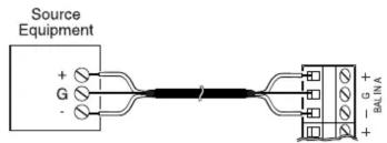
Balanced Connection
Use this wiring when the source equipment supplies a balanced, 3-wire output signal.
For either input, connect the shield wire of the source signal to the “G” terminal of the input. If the “+” signal lead of the source can be identified, connect it to the plus “+” terminal of the input. If the source lead polarity cannot be identified, connect either of the hot leads to the plus “+” terminal. Connect the remaining lead to the minus “-” terminal of the input.
Note: If polarity of the output signal versus the input signal is important, then it may be necessary to reverse input lead connections to correct the “out-of-phase” signal problem.
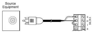
Unbalanced Connection
Use this wiring when the source equipment supplies an unbalanced, 2-wire output signal.
For either input, short the input minus “-” terminals to the input’s ground “G” terminal. Apply the source’s shield to the “G” terminal and the source’s hot lead to the input’s plus “+” terminal.
Features
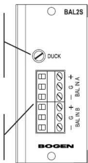
Ducking (Duck)
Controls the level of the output signal from the module when it has been requested to mute its output. The range is adjustable from no reduction in level to full ( 50 dB) muting of the output signal.
Balanced Inputs
Balanced, 3-wire input, each input dedicated to each audio bus. See input wiring section for information on balanced and unbalanced connections.
Muting
This module can be set so that it is muted by higher priority modules. When that is the case, it is always the lowest priority module. It can also be set so that it never mutes.
Channel Gain
This module provides for channel gains of either 0 dB (X1) of gain or 18 dB (X8) of gain. Separate switches service each channel independently.

flowchart
graph TD
    A["CHANNEL GAIN"] --> B["0 dB (X1) Gain Position"]
    A --> C["18 dB (X8) Gain Position"]
    D["MUTING"] --> E["Mute J1"]
    D --> F["No Mute J1"]
    G["CHANNEL A"] --> H["CHANNEL B"]
    I["MUTE J1"] --> J["NO MUTE"]
Block Diagram

flowchart
graph LR
    subgraph_INPUT_A["INPUT A"]
        A1["+ G -"] --> B1["BAL INPUT"]
        B1 --> C1["GAIN X1 X8"]
        C1 --> D1["DUCKING"]
        D1 --> E1["→ BUS A"]
    end
    subgraph_INPUT_B["INPUT B"]
        A2["+ G -"] --> B2["BAL INPUT"]
        B2 --> C2["X1 X8"]
        C2 --> D2["DUCKING"]
        D2 --> E2["→ BUS B"]
        E2 --> F["MUTE LOW"]
    end
Brand : Bogen
Model : BAL2S
Category : Blender