
AP400 - Printer AVISION - Free user manual and instructions
Find the device manual for free AP400 AVISION in PDF.


| Product Type | Monochrome Laser Printer |
| Model | Avision AP400 |
| Print Technology | Laser (LSU) |
| Max Print Speed | 40 ppm (A4) |
| Resolution | 600 x 600 dpi (up to 1200 dpi with Quality Mode) |
| Max Paper Size | A3 (297 x 420 mm) |
| Paper Capacity (Standard) | 500 sheets (Tray 1) + 100 sheets (Manual Tray) |
| Duplex Printing | Automatic built-in (A3, A4, B4, A5, B5, Letter, Legal, custom) |
| Processor | 800 MHz Dual Core Cortex A9 |
| Memory | 512 MB DDR2 SDRAM |
| Connectivity | USB 3.2 Gen 1x1, Gigabit Ethernet (RJ-45), Wi-Fi (optional via WPS) |
| Printer Languages | GDI, PCL, PS |
| Supported OS | Windows 7, 8, 10, 11 |
| Dimensions (W x D x H) | 575 x 563 x 597 mm (22.6 x 21.1 x 23.6 in) |
| Weight | 35 kg (77.2 lb) |
| Power Consumption | Less than 720 W (printing), ECO/Sleep modes available |
| Power Source | 100-120V / 200-240V, 50/60 Hz |
| Operating Environment | Temperature 5-35°C, Humidity 15-85% RH (non-condensing) |
| Monthly Duty Cycle | Up to 200,000 pages (recommended 20,000 pages) |
| Consumables | Toner Cartridge (20K pages @5% coverage), Drum Unit (150K pages), Developing Unit (150K pages), Fuser (300K pages), Waste Toner Can (replace when full) |
| Safety Features | Auto power off, sleep modes, fuser high-temp warning, FCC Class A, CE marking |
| Warranty | Manufacturer warranty (details in manual) |
Frequently Asked Questions - AP400 AVISION
User questions about AP400 AVISION
0 question about this device. Answer the ones you know or ask your own.
Ask a new question about this device
Download the instructions for your Printer in PDF format for free! Find your manual AP400 - AVISION and take your electronic device back in hand. On this page are published all the documents necessary for the use of your device. AP400 by AVISION.
USER MANUAL AP400 AVISION
AP400 Printer User's Guide
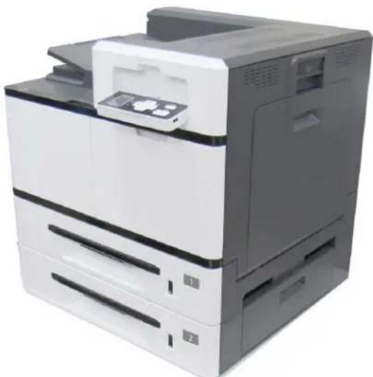
natural_image
Exterior view of a modern office paper printer with front panel and internal components (no visible text or labels)- Getting Started
- Installing Your Machine
- Printing
- Customizing the Product's Configurations
- Maintaining the Machine
- Replacing the Consumables
- Troubleshooting
- Specifications
Regulatory model: PT-1107B
Avision Inc.
Safety During Operation
In this manual, the following important symbols are used:
WARNING:
Indicates potentially hazardous situations, which if instructions are not followed, could result in death or serious injury.
CAUTION:
Indicates a potentially hazardous situation which, if instructions are not followed, may result in minor or moderate injury or damage to property.
Important:
Indicates operational requirements and restrictions. Please read and follow these instructions to ensure a proper operation and to avoid damage to the machine.
Note:
Indicates further explanation or clarification. Reading this is highly recommended.
WARNING:
To avoid hazardous electric shock or fire, do not remove any covers or screws other than those specified in this manual.
CAUTION:
√ To reduce the risk of fire, use only no.26AWG or larger telecommunication line cord.
√ Disconnect the power plug by pulling the plug, not the cable.
Do not touch the metal fingers of the ADF pad module. The edges are sharp and touching them may result in injury.
Notice
Important
- Do not make copies of any item for which copying is prohibited by law.
• Copying the following items are normally prohibited by the local law: - Bank bills, revenue stamps, bonds, stock certificates, bank drafts, checks, passports, driver's licenses.
- This machine is equipped with a function that prevents making counterfeit bank bills. Due to this, images similar to bank bills may not be copied properly.
Copyrights and Trademarks
Ethernet is a registered trademark of Xerox Corporation.
Microsoft, Windows, Windows 7, Windows 8, Windows 10, and Windows 11 are registered trademarks of Microsoft Corporation in the United States and/or other countries.
Other product names used herein are for identification purposes only and may be trademarks of their respective companies. We disclaim any and all rights to those marks.
Warranty
The information contained in this document(s) is subject to change without notice.
The manufacturer makes no warranty of any kind with regard to this material, including, but not limited to, the implied warranties of fitness for a particular purpose.
The manufacturer shall not be liable for errors contained herein or for incidental or consequential damages in connection with the furnishing, performance, or use of this material.
When this printer has no operation for an extended period of time

Note: If the printer is idle for a period of time (for example, overnight), turn off the printer with the power switch. If the printer is idle for a longer period of time (such as holidays), unplug the power cord from the electrical outlet to prevent danger.
Take care to remove the paper from the paper tray and store it in the wrapper to prevent the paper from getting wet.
Disposal of Waste Equipment by Users in Private Union

This symbol on the product or on its packaging indicates that the product can not be disposed of with your other household waste. Instead it should be sent to appropriate facilities for recovery and recycling in an effort to protect human health and the environment. Fore more information about where you can drop off your waste equipment for recycling, please contact your local city office, your household waste disposal service or the shop where you purchased the product.
Federal Communications Commission (FCC) compliance information statement
Part 15
The product has been tested and found to comply with the limits for a Class A digital device pursuant to Part 15 of the FCC Rules. Operation is subject to the following two conditions: (1) this device may not cause harmful interference and (2) this device must accept any interference received including interference that may cause undesired operation.
The FCC Class A limits are designed to provide reasonable protection against harmful interference when the equipment is operated in a commercial environment. This equipment generates, uses, and can radiate radio frequency energy and, if not installed and used in accordance with the instruction manual may cause harmful interference in which case the user will be required to correct the interference at his own expense.
CE
European Union Regulatory Notice
Products bearing the CE marking comply with the following EU Directives:
● Low Voltage Directive 2014/35/EC
● EMC Directive 2014/30/EC
- Restriction of the use of certain hazardous substances (RoHS) Directive 2011/65/EU
CE compliance of this product is valid if powered with the correct CE-marked AC adapter provide by Avision.
This product satisfies the Class A limits of EN55022, EN55024, safety requirements of EN 60950 and ROHS requirements of EN50581.
CE Warning
This is a class A product. In a domestic environment this product may cause radio interference in which case the user may be required to take adequate measures.
Safety Information
When using this equipment, the following safety precautions should always be followed.
Safety During Operation
In this manual, the following important symbols are used:
 | WARNING:Indicates potentially hazardous situations, which if instructions are not followed, could result in death or serious injury. |
 | CAUTION:Indicates a potentially hazardous situation which, if instructions are not followed, may result in minor or moderate injury or damage to property. |
Important:
Indicates operational requirements and restrictions. Please read and follow these instructions to ensure a proper operation and to avoid damage to the machine.
Note:
Indicates further explanation or clarification. Reading this is highly recommended.
The following symbols indicate that the related section includes safety warnings. Specific points of attention are indicated inside the symbol.
 | [General warning] |
 | [Warning of high temperature] |
 | [Warning of danger of electrical shock] |
The following symbols indicate that the related section includes information on prohibited actions. Specifics of the prohibited action are indicated inside the symbol.
 | [Warning of prohibited action] |
 | [Disassembly prohibited] |
The following symbols indicate that the related section includes information on actions which must be performed. Specifics of the required action are indicated inside the symbol.
| [Alert of required action] | |
| [Remove the power plug from the outlet] |
Installation and the Operating Environment

Warning
| Do not install the equipment near direct sun light, heating or air conditioning units. Direct sunlight or high temperature may damage the machine. |  |
| Do not install the equipment in a humid or dusty place. If dust or dust adheres to the power plug, clean the plug to avoid fire or electric shock. |  |
| Keep the vent hole on the back of the printer at least 10 cm away from the wall to avoid overheating and fire. |  |
| Do not place or store the device:OutdoorsNear excessive dirt or dust, water, or heat sourcesIn locations subject to shocks, vibrations, high temperature or humidity, direct sunlight, strong light sources, or rapid changes in temperature or humidity |  |
| Place the equipment securely on an even, flat surface. Tilted or uneven surfaces may cause mechanical or paper-feeding problems. |  |
| Do not locate the device on rackety or aslope tables. Do not locate the device on unstable surface. The device may fall down and this may result in injury. |  |
| Place the device close enough to the computer so that the interface cable can easily reach between the device and the computer. | |
| Do not place a coffee cup, vase, or other liquid-filled container on the machine. Spillage can damage the machine's electrical parts and insulation. |  |
| Make good use of the recycled paper while printing. |

Caution
| Place the device in an independent, well-ventilated area. |  |
| Place the device in a place with good environmental conditions. Operating the machine beyond the recommended temperature and humidity may cause an electrical fire. |  |
| Do not place heavy objects on the unit. It may cause unbalance and the device may fall down. This may result in injury. |  |
| Do not place the device in any position that may obstruct the output of the unit, as it may cause paper jams. |  |
Safety Information During Operation

Warning
| To prevent fires, do not use flammable sprays near the machine. |  |
| Never attempt to open any fixed cover. Otherwise there is danger of electric shock, fire and laser beam and may cause blindness. |  |
| Never disassemble, modify, or attempt to repair the device or device option yourself, except as specifically explained in the device's documentation. This could cause fire, electrical shock, or injury. |  |
| Do not attempt to alter the machine or its parts. Avoid contact with the internal high voltage part or the laser light beam, it may cause electric shock or blindness. |  |
| If this product becomes inordinately hot or emits smoke, or unusual odor o noise, immediately turn OFF the power switch, unplug the power cord from the power outlet, and then call your authorized service representative. If you keep on using it as is, a fire or electrical shock could result. |  |
| Take care not to drop paper clips, staples, or any other metal objects into the machine. |  |
| The inside of this product has areas subject to high temperature, which ma cause burns. When checking the inside of the unit for malfunctions such as paper mis-feed, do not touch the locations (around the fusing unit, etc.) which ar indicated by a “Caution! Hot Surface” caution label. |  |
| Under normal conditions the small quantities of ozone gas produced by the machine are harmless. However, if the machine is used for an extended period or within a small room, you should make sure that the area is adequately ventilated. Also ventilate the room if you notice the machine smells after a period of frequent or extended use. |  |
| Do not attempt to remove the covers and panels which have been fixed to product. Some products have a high-voltage part or a LSU beam source inside that could cause an electrical shock or blindness. |  |
| Do not modify this product, as a fire, electrical shock, or breakdown could result. If the product employs a LSU printhead, the LSU beam source could cause blindness. |  |
| If this product has been dropped or its cover damaged, immediately turn OFF the power switch, unplug the power cord from the power outlet, and then call you authorized service representative. If you keep on using it as is, a fire or electrical shock could result. |  |
| Take appropriate emergency measures when the following conditions occurWhen toner gets into your eyes, wash it off with water until your eyes are not painful. If the situation is serious, ask a doctor for treatment.When the toner gets on your skin, wash it off with soap and rinse it off.When you are in the toner inlet, leave the dust location immediately and rinse with plenty of water.When the toner is in the abdomen, spit it out and consult a doctor. |  |
| Do not use the device with wet hands. |  |
| Unplug the device and the USB cable, and refer servicing to qualified service personnel under the following conditions:Liquid has entered the device.Object has entered the device.The device has been dropped, or the case has been damaged.The device does not operate normally (i.e. appearance of smoke, strange smell, odd noise, etc.), or exhibits a distinct change in performance. |  |

Caution
| When there is paper jam inside the machine, be sure to remove it thoroughly. The remaining paper in the machine may cause a fire. When the paper is attached to an invisible or difficult-to-see area, do not remove it by force to avoid injury and contact the service personnel or dealer for help. |  |
| The temperature inside of the machine may be very hot. When the paper jam is released, note any warning labels and do not touch it to avoid burns. It is recommended to clear the jam after the machine has cooled down. |  |
| When clearing paper jams, refer to the instructions in this manual. |  |
| When using a large number of copies of the machine for a long time, keep indoor air flowing. Otherwise you may feel a headache. |  |
| Unplug the device's power cord and USB cable before cleaning. |  |
About the Consumables

Caution
| Do not unpack the consumables and store the machine's consumables in any of these locations:OutdoorsNear excessive dirt or dust, water, or heat sourcesIn locations subject to shocks, vibrations, high temperature or humidity, direct sunlight, strong light sources, or rapid changes in temperature or humidity |  |
| Do not throw the toner cartridge into the fire. After the toner remaining in crucible comes into contact with the fire, the powder may explode and cause personal injury. |

Caution
| Do not discard the discarded toner cartridges. Please put the used waste toner cartridges in the supplied plastic bags and return them to the dealer or service personnel. (For the customer service locations around the company, please refer to our website.). The latter will recycle the used toner cartridge in accordance with relevant regulations. |  |
| The used consumables must be disposed of properly and in accordance with local environmental regulations, or disposed of by the company's designated dealer. |  |
Safety Information when using power cord and the USB cable

Warning
| Plug the power cord securely into the outlet. Do not touch the pins of the power cord plug with any metal objects as they may touch dangerous voltage points or short circuit. This can cause fire, electric shock or injury. Failure to do so may result in a fire or electric shock. |  |
| Before disconnecting the plug, turn the machine off. Make sure your hands are dry. Hold the plug itself, not its cord, when disconnecting it from the receptacle. |  |
| Do not share the power with other high-powered devices, as this may result in fire or electric shock. |  |
| Do not use extension cords as this may result in fire or electric shock. |  |
| Always use the correct AC power source. For future transportation and handling, please keep all packaging materials for this product. |  |
| Use only the USB cable that came with your device and avoid abrasions, cuts, fraying, crimping, and kinking. Using any other USB cable could cause fire, electrical shock, or injury. |  |
| Do not store the cables in the following locations:OutdoorsNear excessive dirt or dust, water, or heat sourcesIn locations subject to shocks, vibrations, high temperature or humidity, direct sunlight, strong light sources, or rapid changes in temperature or humidity |  |
| Keep the supplied USB cable, etc., in a location that is out of reach of children to avoid the risk of injury. |  |
| Please put the packaging materials such as the supplied plastic bags in a place that children cannot obtain or discard them to avoid the risk of suffocation. |  |

Caution
| If you are not using the device for a long time, remove the USB cable from the connector. |  |
| This product has a power-saving mode and a standby mode. The zero-energy state can be achieved only when the product is connected without any external input power. | |
| At least every year, please disconnect the power cord from the wall outlet to check whether the power cord is exposed, damaged, cracked, dent, hot, pin deformation or any burnt marks. If these conditions exist, please do not use the power cord again and contact the authorized service personnel or dealer. |  |
| Make sure the power cord is plugged into a grounded electrical outlet, otherwise it may cause a fire or electric shock. | |
| Be sure to fully plug the power cord into a wall outlet. Failure to completely insert may cause unstable connections and heat build-up, creating an unsafe condition. | |
| When disconnecting the power cord from the wall outlet, be sure to pull the plug, not the power cord, as this may damage the power cord and cause a fire or electric shock. |  |
| To repair the machine, be sure to disconnect the power cord from the wall outlet. | |
| Make sure the power cord is firmly secure and will not trip over. |
SAFETY INSTRUCTION
This printer is a printer which is operated by means of a LSU (Laser Scanning Unit). There is no possibility of danger from the LSU, provided the printer is operated according to the instructions in this manual. Since radiation emitted by the laser beam is completely confined within protective housings and external covers, the laser beams cannot escape from the machine during any phase of user operation.
Table of Contents
1 Getting Started .... 1
Introduction......1
Features....1
External View....3
The Front View ....3
The Rear View....4
Package Contents....5
The Control Panel....6
Preinstallation Information....7
2 Installation 8
Precautions....8
Installing the Toner Cartridge 9
Installing the Developing Unit....16
Installing the Drum Unit....19
Lifting Up the Output Bin....21
Loading The Main Input Tray....22
Paper sizes and weights used for Tray 1\~4 ....24
Loading the Manual Tray 25
Paper sizes and weights used for Manual Tray 27
Connecting to Power 29
Turning On The Printer....29
Connecting to the Network....30
Installing the Printer Driver 31
For USB Interface Users ....31
For Network Interface Users .... 33
Changing the Product's IP Address in a Wired Network....35
3 Printing 36
Normal Printing....36
2-Sided Printing 37
Combining Multiple Pages into One Sheet of Paper....39
Enhancing Your Print Quality....41
More Printing Features....42
The Basic Tab....42
The Paper Tab....44
The Layout Tab 45
The Watermark Tab.... 47
The Duplex Tab 52
The Job Build Tab.... 55
The More Tab 56
4 Configuring the Machine 57
Customizing System's Settings via the Control Panel....57
Menu Items on the LCD Screen....58
Customize System's Settings via the Embedded Web Page 62
Setting Items on the Webpage 63
5 Troubleshooting......67
Monitoring Your Printer Using Printer Status Monitor....67
Accessing Printer Status Monitor 67
Getting Printer Status Details 68
Clearing A Warning or Error Message 71
Technical Support 97
6. Maintaining the Machine 98
Cleaning the Drum Charger 98
Cleaning the Paper Tray Rollers....100
Cleaning the Manual Tray Roller 102
Installation Step 103
Cleaning the Toner Cartridge....104
Remove the Toner Cartridge 104
Install the Toner Cartridge.... 105
Cleaning the Paper Path....106
7. Replacing the Consumables 108
Replacing the Waste Toner Can....110
Removing the Waste Toner Can 110
Reinstalling the Waste Toner Can 112
Replacing Toner Cartridge....113
Removing the Toner Cartridge 113
Installing the Toner Cartridge.... 114
Replacing the Paper Tray Rollers....115
The removing steps.... 115
The reinstallation steps.... 117
Replacing the manual tray rollers and pad....118
The removing procedure 118
The reinstallation procedure 119
Replacing the Drum Unit .... 120
The Removing Procedure....120
Reassembling Steps:....121
Replacing the Developing Unit....123
The Removing Steps: 123
Replacing the Fuser....127
The Removing Steps ...... 127
Thank you for choosing Avision's state-of-the-art printer which can be used for local printing and network printing up to A3 size.
Features
This product provides the following features to make your print out more efficient and effective.
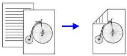
- Print on Both Sides: Prints two pages (one on each side) on a single sheet of paper.
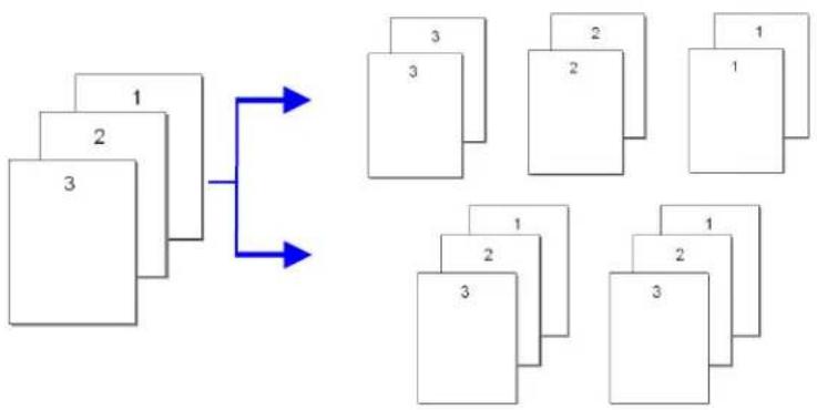
• Collate: Prints multiple copies at one time and sorts the printed pages.
flowchart
graph TD
    A["1"] --> B["2"]
    B --> C["3"]
    C --> D["3"]
    D --> E["2"]
    E --> F["1"]
    C --> G["3"]
    G --> H["2"]
    H --> I["1"]
    G --> J["3"]
    J --> K["2"]
    K --> L["1"]
    style A fill:#f9f,stroke:#333
    style B fill:#f9f,stroke:#333
    style C fill:#f9f,stroke:#333
    style D fill:#f9f,stroke:#333
    style E fill:#f9f,stroke:#333
    style F fill:#f9f,stroke:#333
    style G fill:#f9f,stroke:#333
    style H fill:#f9f,stroke:#333
    style I fill:#f9f,stroke:#333
    style J fill:#f9f,stroke:#333
    style K fill:#f9f,stroke:#333
    style L fill:#f9f,stroke:#333
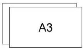
• Support A3 size: The product allows you to print up to A3 size.
- Print Multiple Pages on a Single Sheet: Prints two or four pages of the original on a single sheet of paper. A maximum of 16 pages can be printed on a single sheet of paper.
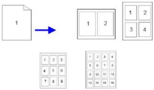
flowchart
graph TD
    A["1"] --> B["1 2"]
    B --> C["1 2 3 4 5 6 7 8 9"]
    D["1 2 3 4 5 6 7 8 9"] --> E["1 2 3 4 5 6 7 8 9 10 11 12 13 14 15 16"]
- Print Watermark: Print text such as confidential, important content or image in the background.
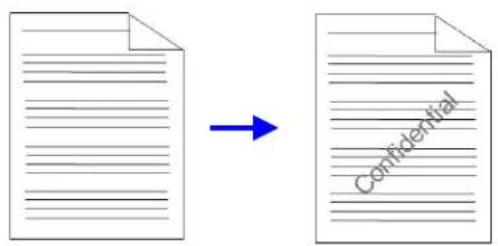
External View
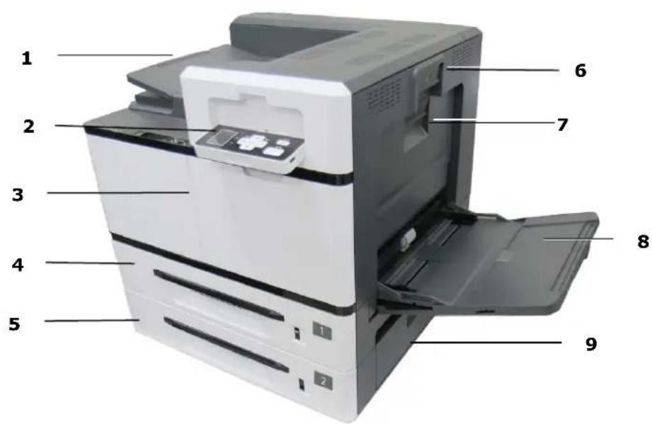
The Front View
-
Top Output Bin
-
Side Cover Handle
-
Control Panel
-
Manual Tray Handle
-
Front Cover
-
Manual Tray
-
Tray 1
-
Side Door of Tray 2
-
Tray 2
[Non-Text]
The Rear View
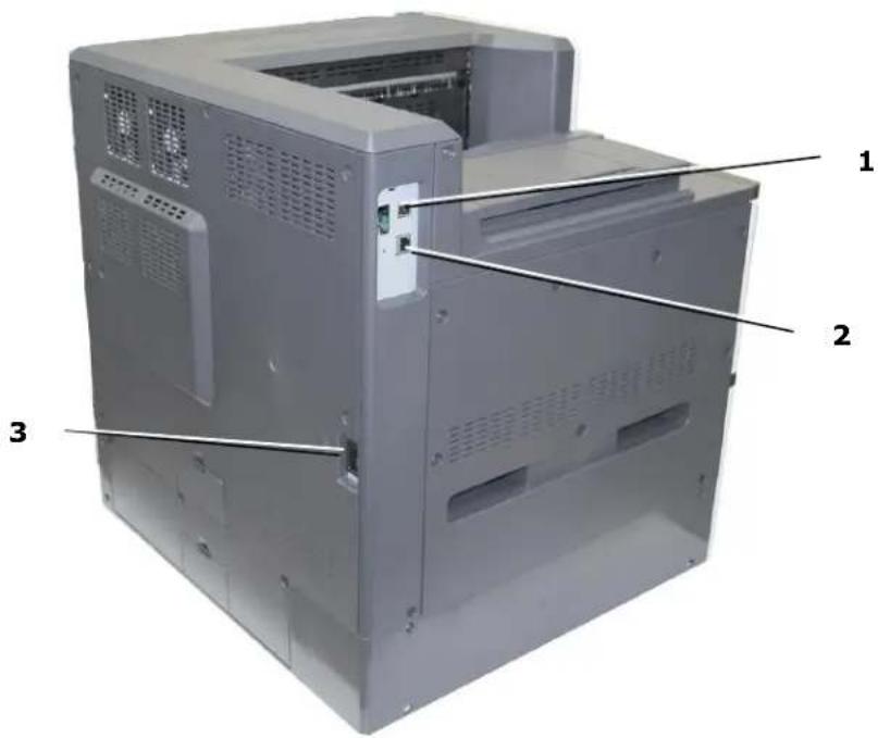
| 1. USB 3.2 Gen 1x1 | Used to connect to a computer via a USB cable. |
| 2. LAN Port | Used to connect to a network via an etheret cable. |
| 3. Power Receptacle | Used to plug a power cable. |
Package Contents
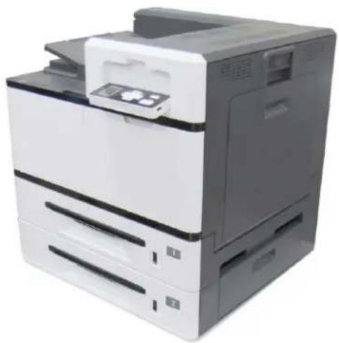
natural_image
Exterior view of a modern office paper printer with front panel and control panel (no visible text or symbols)Main Unit
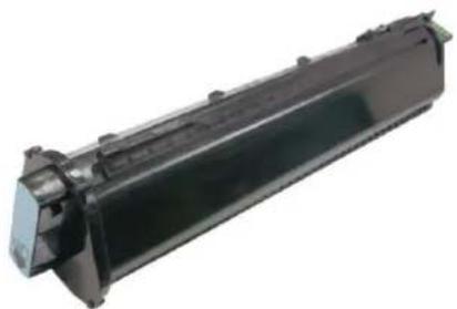
natural_image
Exterior view of a black cylindrical electronic component with mounting holes (no text or symbols visible)Toner Cartridge

natural_image
Close-up of a black electronic component with a green tab and metallic contacts (no visible text or symbols)Drum Unit
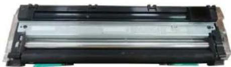
natural_image
Exterior view of a black plastic electronic device with two cylindrical modules (no visible text or symbols)Developing Unit
natural_image
Line drawing of a cord with two leads tied together (no text or symbols)Power Cable

USB Cable
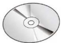
Software CD (including driver and user's guide)
The Control Panel
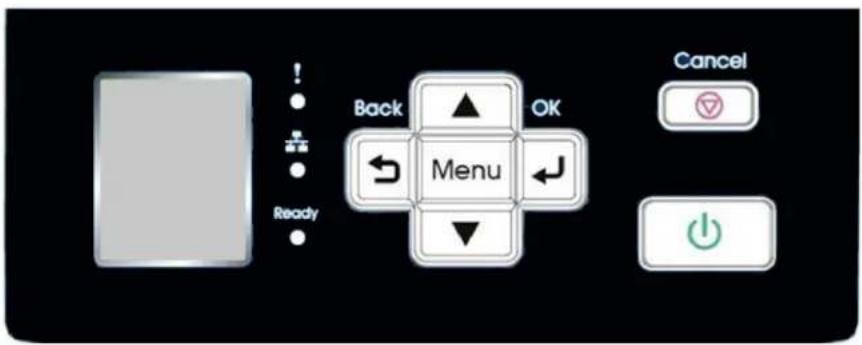
Buttons







Description
Cancel button: Stops printing at any time and lets you exit the menu.
Power button: Press to turn on or long press to turn off.
Menu: Press to select settings.
Up/Down Key: Press to scrolls through the options.
Confirm key: Accept an option.
Back key: Return to the previous menu level.
Error LED: Flashes in red to indicate error status.
LAN LED: Turns solidly on in green color when the network cable is connected. Turns off when the network cable is unplugged.
Ready LED: Turns solidly on in green in ready status.
LCD-Display: Displays status, options and errors.
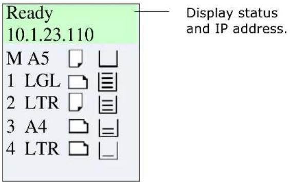
LCD-Display: Display status, options, and errors.
| Item | Description |
| ReadyIP Address | A valid IP address indicates a successful network connection and a valid IP obtaining from DHCP server.0.0.0.0 indicates the network cable has not been connected or DHCP server is not available. |
| M/1/2/3/4 | M: Indicates Manual Tray。1~4: Indicates the 1^st , 2^nd , 3^rd , or 4^th tray. (The 3^rd and 4^th tray are optional) |
| A4 | Indicate paper size in tray. |
 | Indicate paper orientation in tray. |
 | Indicate paper volume percentage in tray (0%、25%、50%、75%、100%)。0%: /25%: /50%: /75%: /100%: Only 100% or 0% can be displayed in the Manual Tray.☒ : Tray can not be used. |
2 Installation
Precautions
- Do not install the equipment near heating or air conditioning units.
- Do not install the equipment in a humid or dusty place.
- It is recommended to use recycled paper when printing.
- Place the equipment in a separate area with good ventilation.
- It is recommended to make good use of recycled paper for copying.
- The equipment is equipped with both the power-saving and standby modes. The equipment is not able to achieve zero energy consumption until it is disconnected from any external power supply.
- Do not dispose of the waste toner can. Put the used waste toner can into the bundled plastic bag, and then return it to a dealer or service representative (About our customer service locations everywhere, please refer to our web site at www.avision.com). The latter recycles or deals with the collected waste toner cans in accordance with the relevant regulations.
- Be sure to use the correct AC power supply.
- Retain the box and packing materials for shipping purposes.
Removing the Box and Packing Material
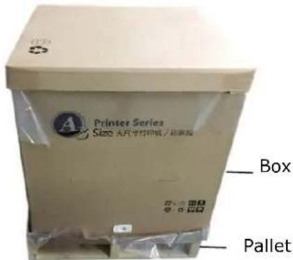
The printer box is illustrated as shown in the figure below, which is divided into four parts:
- Printer main unit (Packed inside the carton)
- Pallet (Under the carton)
- All Accessories (packed inside the carton)
Unpacking Steps
- Place the printer box on a flat, and horizontal surfacen and do not place any objects in front of the printer.
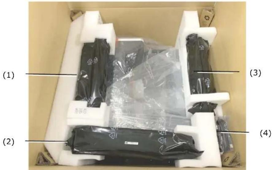
- Open the printer box with a utility knife, and then take out all the accessories [including (1) Developing Unit, (2) Toner Cartridge, (3) Drum Unit, (4) Power Cord, Manual/CD] and cushion, as shown in below:
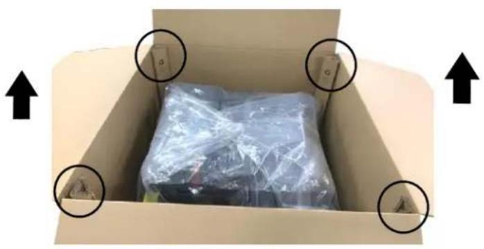
- Remove four box supports.
natural_image
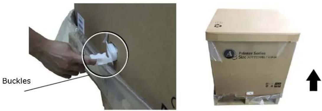
Interior view of a cardboard box with visible plastic wrap and four circular arrows pointing upward (no text or symbols)- Remove all buckles on the sides of the printer box and pull the printer box upward.
Removing the Shipping Tapes on the Machine
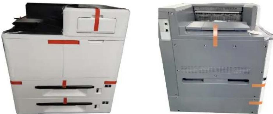
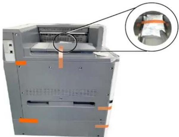
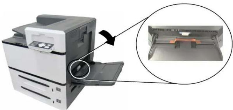
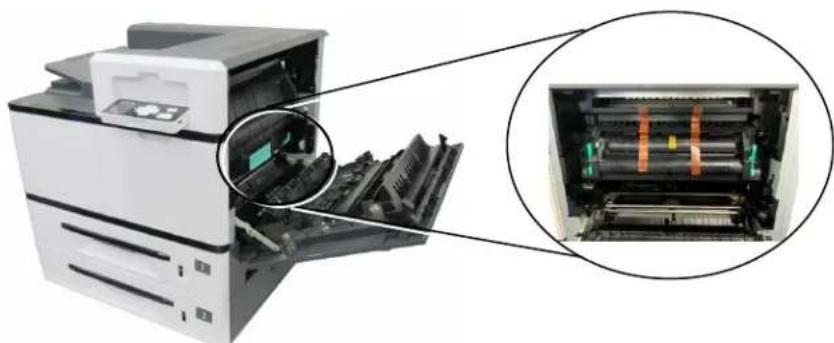
Remove the protective tapes, and desiccant on the machine, as shown in the figure below.
natural_image
Two views of a laboratory instrument with red and orange bands, shown from front and side (no visible text or symbols)Remove the tapes on the front and rear side of the machine.
natural_image
Exterior view of a gray industrial machine with orange tape and a magnified inset showing internal components (no visible text or symbols)Remove the tapes and desiccant on the top.

natural_image
Diagram of a printer with internal components and a magnified inset showing internal structure (no text or symbols)Pull the Paper Tray and remove the tapes.
natural_image
Diagram of a printer with an inset close-up showing internal components (no text or symbols)Open the Manual Tray and remove the tape on the paper guide.
natural_image
Diagram of an open printer with internal components, showing internal structure and external view (no text or symbols)Open the Side Door and remove the tapes on the Fuser.
Removing the Locking Latch on the Machine
- Pull the handle down to open the Side Door as shown.
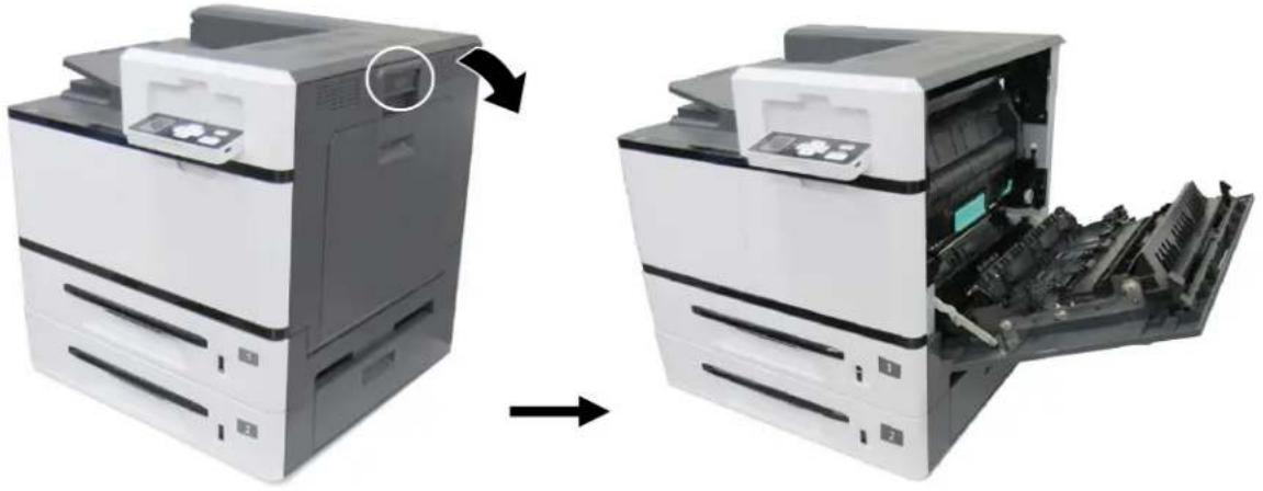
natural_image
Two views of a printer showing the left and right sides of an open image, with no visible text or symbols.- Remove the Latch and its instruction sheet by pressing the bolt with one hand and pulling the latch with the other hand as shown in below. The latch is designed to protect the inside of the printer during transportation.
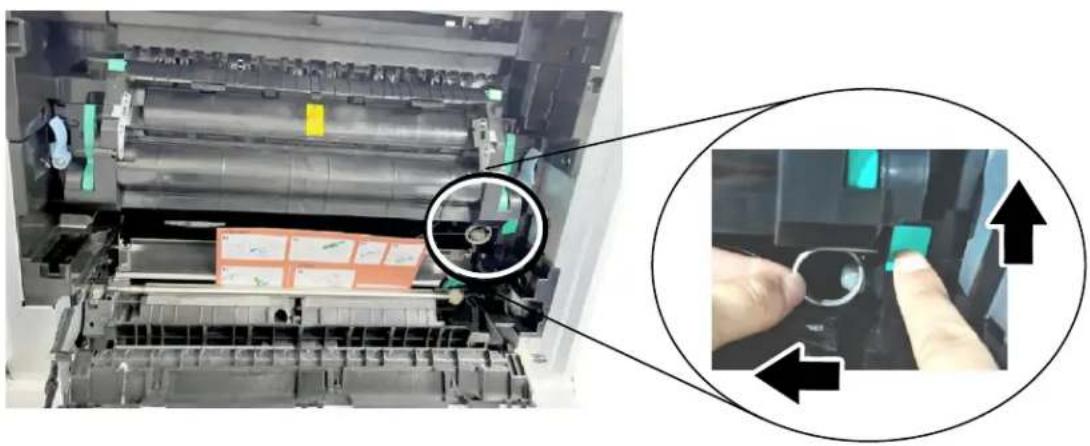
natural_image
Close-up of a printer's internal structure with a magnified inset showing hand press application (no text or symbols visible)Installing the Toner Cartridge

Important!
When you unpack the machine, a toner cartridge has been packed separately besides the machine. Please remove the package cushion and tapes on the toner cartridge before using it.
Follow these steps to install the Toner Cartridge:
- Remove the package cushion and tapes on the toner cartridge. Tilt the toner cartridge up and down and then right and left 10 times to distribute the toner evenly inside the toner cartridge.

natural_image
Close-up of a cylindrical mechanical component with a highlighted section and an arrow indicating rotation (no visible text or symbols)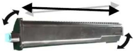
natural_image
Mechanical component with rotational arrows indicating motion or force (no text or symbols)
WARNING!
- Be careful not to inhale toner.
• To avoid print quality problems, DO NOT touch the toner rollers. - If toner gets on your clothing or other fabric, wipe off the toner with a dry cloth. Wash the items in cold water and dry them in the shade.
-
To prevent the toner cartridge from damage, do not expose it more than several minutes.
-
Open the front cover by pulling the handle as shown.
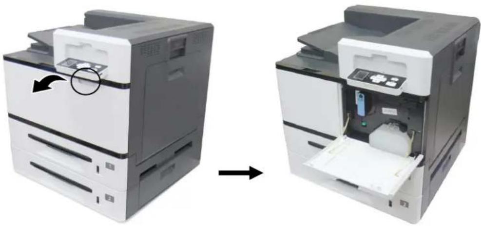
natural_image
Two views of a printer showing internal components before and after assembly (no text or symbols visible)- Hold the handle of the toner cartridge and insert it to its proper position as shown.
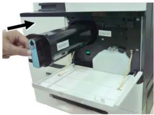
natural_image
Hand inserting a device into an open printer case, showing internal components and no visible text or symbols- Close the Front Cover.
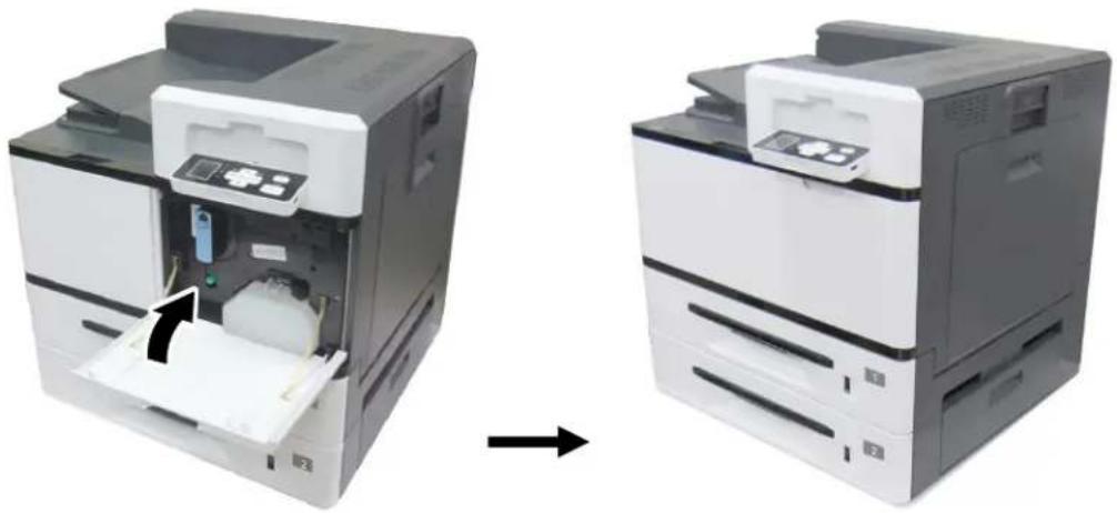
natural_image
Two views of a printer showing internal components before and after assembly (no text or symbols visible)Installing the Developing Unit
Follow these steps to install the Developing Unit:

Caution!
To prevent damage to the Developing Unit, do not expose it to light for more than a few minutes.
- Remove the plastic bag and protective package including protective film①, plugs②, tapes③, and the sponge④ in the toner exit hole.
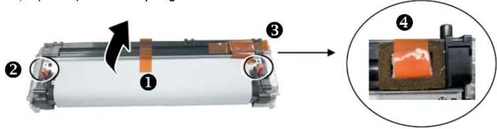

Important!
Do not remove the transparent plastic protective cover on the surface of the developing unit as shown in the figure to avoid abnormal images.
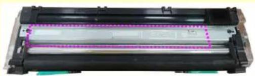
natural_image
Close-up of a black cylindrical electronic component with a purple dotted rectangular outline and green base (no visible text or symbols)- Pull the handle down to open the Side Door as shown.
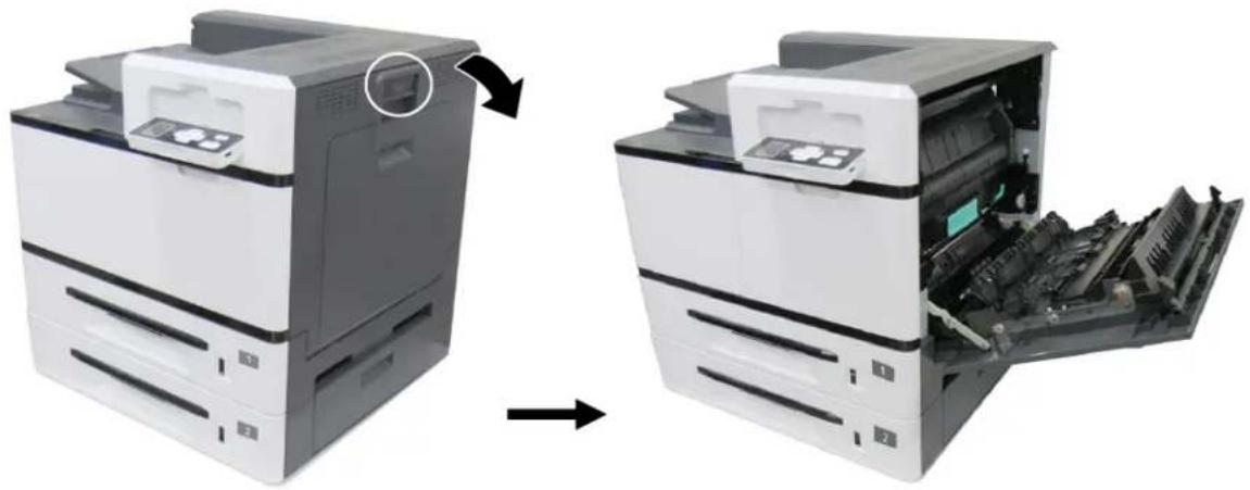
natural_image
Two views of a printer showing internal components before and after processing (no text or symbols visible)- Open the paper guide latch in a clockwise direction ①, and then push up ② to fix the paper guide.
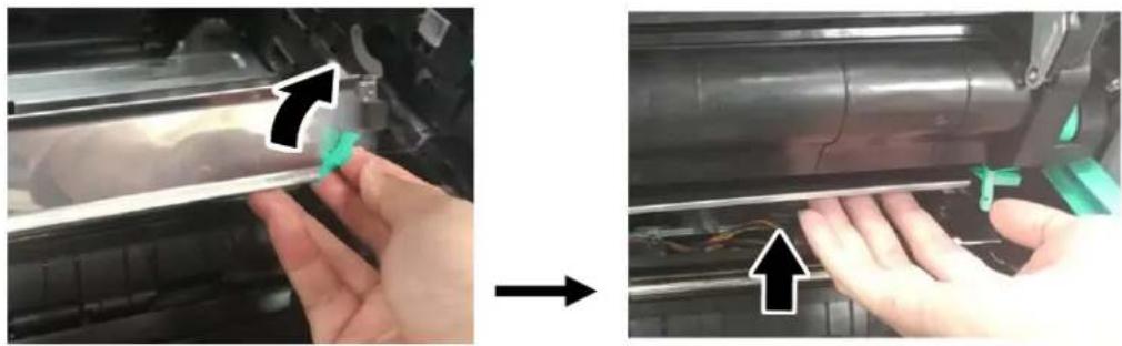
natural_image
Close-up of hands installing or adjusting a mechanical component, showing a blue clip and green tool (no text or symbols visible)- Open the handle of the developing unit and hold the handle with both hands, as shown in the figure below.
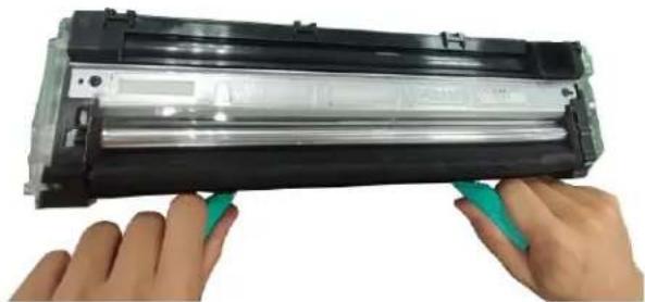
natural_image
Close-up of hands holding a black plastic cylindrical device with green clamps, no visible text or symbols- Hold the handle with both hands, placing the front end of the developing unit to the top of the rails on both sides ①, and then gently push the developing unit into the machine along the rails ②. Make sure the handles are closed and left flat on the surface of the developing unit as shown in below ③.
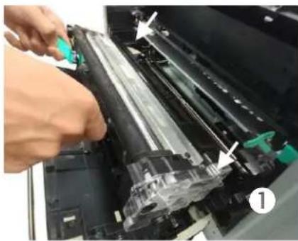
natural_image
Close-up of a hand operating a printer with a green tool, showing mechanical components and a numbered label (1) — no readable text or symbols present.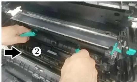
natural_image
Close-up of hands installing or adjusting a mechanical component with green arrows pointing to parts (no visible text or symbols)
natural_image
Close-up of a printer's internal structure with green plastic zones (no visible text or symbols)3
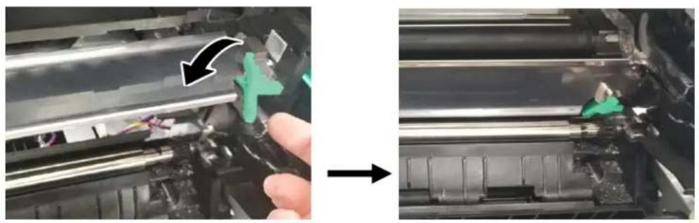
- Pull down the latch of the paper guide counterclockwise to restore the latch of the paper guide to its original status.
natural_image
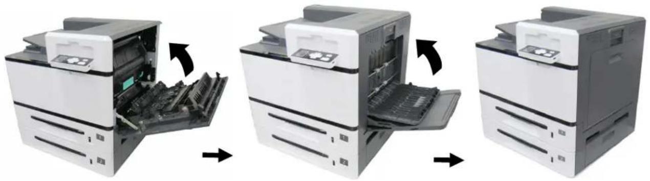
Close-up of a hand holding a mechanical component with green tool, before and after assembly (no visible text or symbols)- Close the Side Door and then the Duplex Unit Cover as shown.
natural_image
Three-step illustration of a printer's internal structure showing open, closed, and closed states (no text or symbols)Installing the Drum Unit
Follow these steps to install the drum unit:
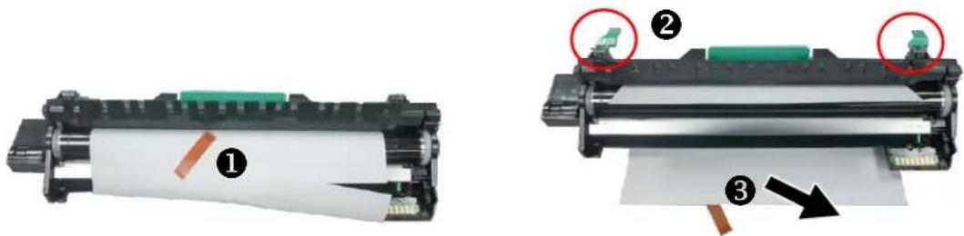
- Remove the plastic bag, tape, and then pull down the Release Arms to pull out the protective film.
natural_image
Two views of a printer with paper roll and green clip, showing mechanical components (no text or symbols visible)- Pull up the Release Arms on both ends.

natural_image
Two views of a black rectangular electronic component with teal internal bands, showing a transformation from left to right (no text or symbols visible)
Caution!
To prevent damage to the Drum Unit, do not expose it to light for more than a few minutes.
- Pull down the hande to open the side door as illustrated.
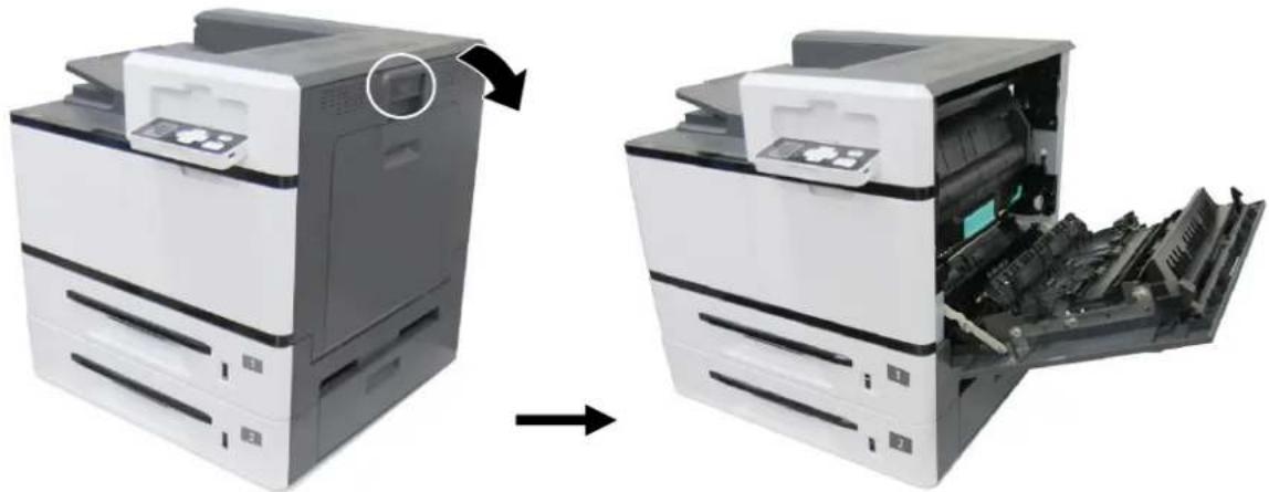
natural_image
Two views of a printer showing internal components before and after processing (no text or symbols visible)- Holding the handle of the Drum Unit, insert the Drum Unit horizontally into the slot along the top of the support frame on both sides, as shown in the figure.
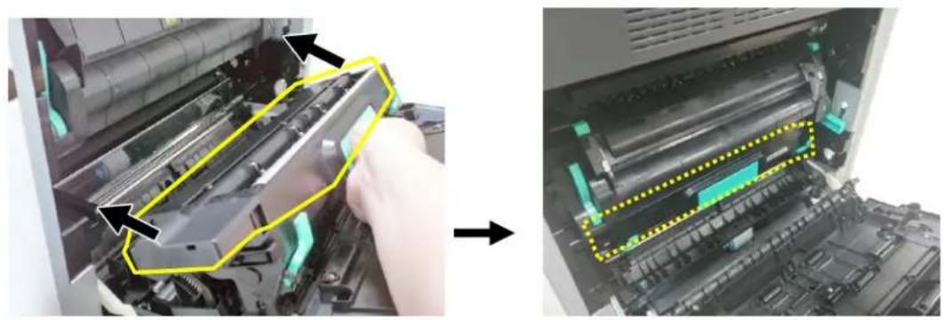
natural_image
Two-panel image showing a printer's internal structure before and after assembly, with arrows indicating process direction (no text or symbols)- Close the Side Door and then the Duplex Unit Cover as shown.
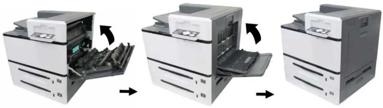
natural_image
Three-step illustration of a printer's internal structure showing open, closed, and closed-up views (no text or symbols)Lifting Up the Output Bin
Lift the output bin up to the stuck position, and open the extension.
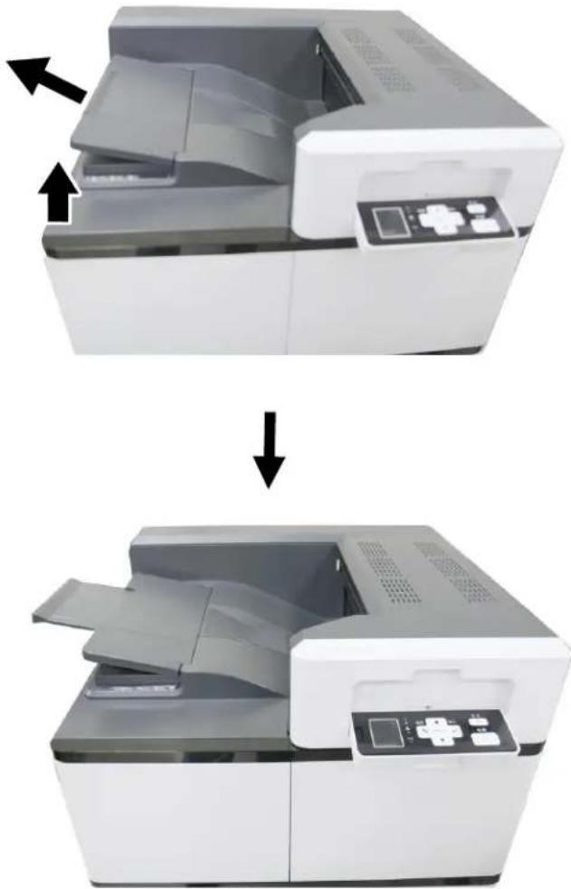
natural_image
Two-step illustration of a digital scanner device showing internal components before and after processing (no text or symbols)Loading Paper Into The Main Input Tray
To insert paper up to B4 size to the main input tray,
- Fan your paper first to ensure that the pages do not stick together.

natural_image
Illustration of a hand holding a stack of papers with a directional arrow indicating rotation (no text or symbols)- Align the edges of the documents by tapping the bottom of the stack against the table. Rotate the stack 90 degrees and repeat.
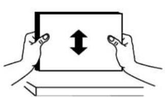
natural_image
Illustration of two hands holding a tablet with bidirectional arrow (no text or symbols)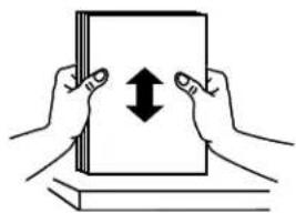
natural_image
Illustration of two hands holding a stack of books with an upward arrow between them (no text or symbols)- Pull out the main input tray.
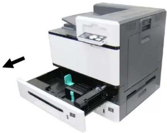
natural_image
Exterior view of a printer with internal components and a paper feeding into a drawer (no text or symbols visible)- Push the center of the width guide tab as shown, and move the width guide to the correct position for the paper being loaded.
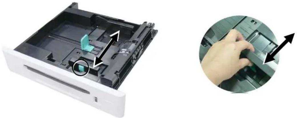
natural_image
Exterior view of a white electronic device with internal components and a magnified inset showing hand pressing a component (no text or symbols visible)- Squeeze the bottom of the length guide tab inward as shown, and slide the guide to the correct position for the paper size being loaded.
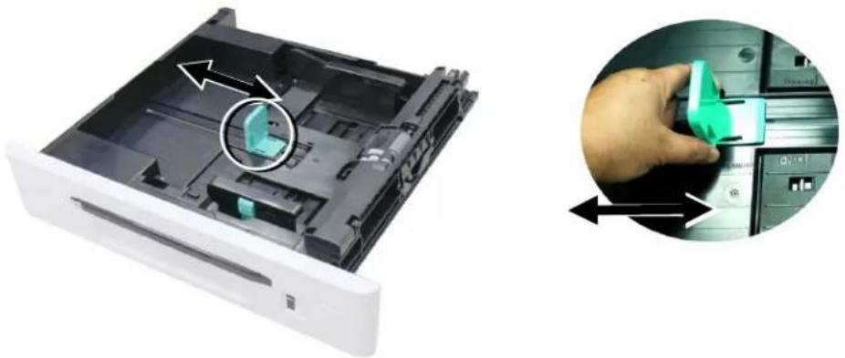
natural_image
Disassembled printer drawer with green plastic clip and directional arrows indicating assembly (no text or symbols)- Load the paper stack face up. Note the print side face up for single-sided printing.
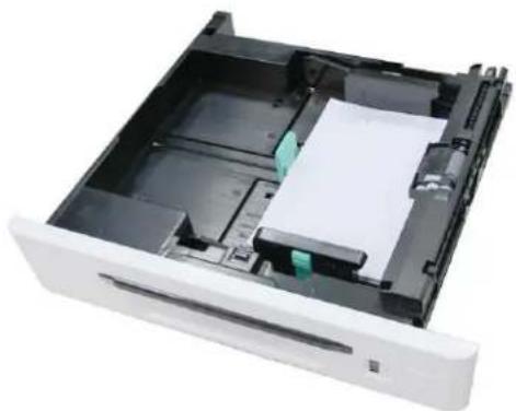
natural_image
Interior view of a white electronic device with internal compartments and a green component (no visible text or symbols)- Insert the tray.

natural_image
Exterior view of a printer with paper feed and paper holder, showing internal components (no text or symbols visible)Paper sizes and weights used for Tray 1\~4
| Paper capacity | 500 pages (70g/m2 plain paper) |
| Paper size | A3 (ISO) (297 x 420 mm) |
| A4 (ISO) (297 x 210 mm) | |
| A5 (ISO) (148 x 210 mm) | |
| B4 (JIS) (257 x 364 mm) | |
| B5 (JIS) (257 x 182 mm) | |
| Letter (215.9 x 279.4) | |
| Legal (215.9x355.6 mm) | |
| Ledger (Double Letter) (279.4 x 431.8 mm) | |
| Paper weight | 60 ~ 105 g/m2 (16 ~ 28 lb.) |

Note:
- To ensure the best quality printing and copying, please use the paper or media which we have recommended.
• Make sure to fan your paper before loading it to the paper tray. - If there is instruction about the printing side on the packaging of your paper, please follow the instruction to load your paper properly with the correct printing side to the paper tray.
- If the printing quality is not satisfactory or paper jams are easily to occur, turn over the paper stack so that the top page is now on bottom and then reload it to the paper tray.
- Pack and seal the remaining paper with the original packaging and store the paper in a dark and dry location away from the sunshine. Paper which collects much moisture is easy to cause jam during printing.
Loading Paper Into the Manual Tray
When you need to print different size paper, you can use the manual tray. The main input tray can load paper up to B4 size. The 2^nd tray can load paper up to A3 size.
- Open the manual tray by grasping the handle and pull it down.
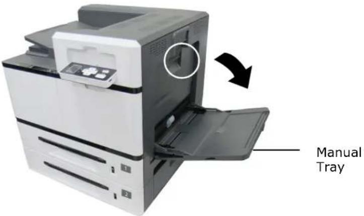
- Pull out the tray extension.
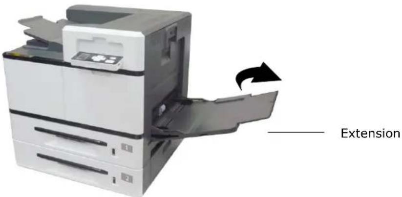
- Fan your paper first to ensure that the pages do not stick together.

natural_image
Illustration of a hand holding a folded document with a scroll and arrow indicating rotation (no text or symbols)- Align the edges of the documents by tapping the bottom of the stack against the table. Rotate the stack 90 degrees and repeat.
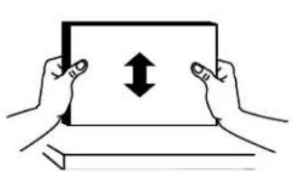
natural_image
Illustration of two hands holding a tablet with bidirectional arrow (no text or symbols)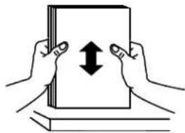
natural_image
Illustration of two hands holding a stack of books with a double-headed arrow indicating upward motion (no text or symbols)- Load the paper stack face down. Note the print side facedown for single-sided printing.
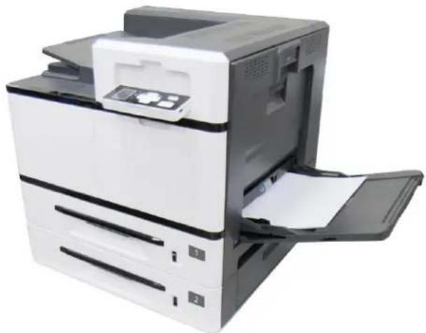
natural_image
Exterior view of a white paper airplane with open door and paper feed (no visible text or symbols)- Slide the paper guides so that they lightly touch the paper stack.
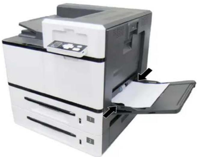
natural_image
Exterior view of a printer with paper being inserted (no visible text or symbols)Paper sizes and weights used for Manual Tray
| Paper capacity | 100 pages (70g/m2 plain paper) |
| Paper size | A3 (ISO) (297x420 mm) |
| A4 (ISO) (297x210 mm) | |
| A5 (ISO) (148 x 210 mm) | |
| A6 (ISO) (106x148 mm) | |
| B4 (JIS) (257x364 mm) | |
| B5(JIS) (257x182 mm) | |
| B6 (JIS) (128x182 mm) | |
| Letter (215.9x279.4) | |
| Legal (215.9x355.6 mm) | |
| Legal 13 (216x330 mm) | |
| Ledger (Double Letter) (279.4x431.8 mm) | |
| 8K (267x390 mm) | |
| 16K (195x267 mm) | |
| PostCard (100x148 mm) | |
| Min. Size: 100 x145 mm | |
| Max. Size: 304.8 x 431.8 mm | |
| Paper weight | 60 ~ 210 g/m2 (16 ~ 56 lb.) |
* A6 □(SEF), B6 □(SEF), and Post Card (SEF) support only single-sided print in manual tray.
Detected Paper Size for Manual Tray
| Paper Size in Manual Tray | Detected Paper Size in Manual Tray |
| A3 | A3 SEF |
| A4_SEF | ISO 216 : A4 SEFNorth America : LTR SEF |
| A4_LEF | ISO 216 : A4 LEFNorth America : LTR LEF |
| A5_SEF | ISO 216 : A5 SEF |
| B4 (JIS) | B4 SEF |
| B5_SEF/EXEC (JIS) | B5 SEF |
| B5_LEF (JIS) | B5 LEF |
| LTR_SEF | ISO 216 : A4 SEFNorth America : LTR SEF |
| LTR_LEF | ISO 216 : A4 LEFNorth America : LTR LEF |
| LGL | LGL SEF |
| Ledger (DLT) | Ledger SEF |
| A6 SEF (ISO) | A6 SEF |
| B6 SEF (JIS) | B6 SEF |
| Legal 13 SEF | LGL SEF |
| 8K SEF | Ledger SEF |
| 16K SEF | ISO 216 : A4 SEFNorth America : LTR SEF |
| PT SEF | A6 SEF |
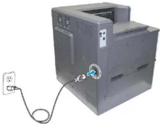
- Connect the of the power cable to the power jack of your product.
natural_image
Exterior view of a computer tower with a cable and power outlet, no visible text or symbols- Connect the other end to an appropriate power outlet.
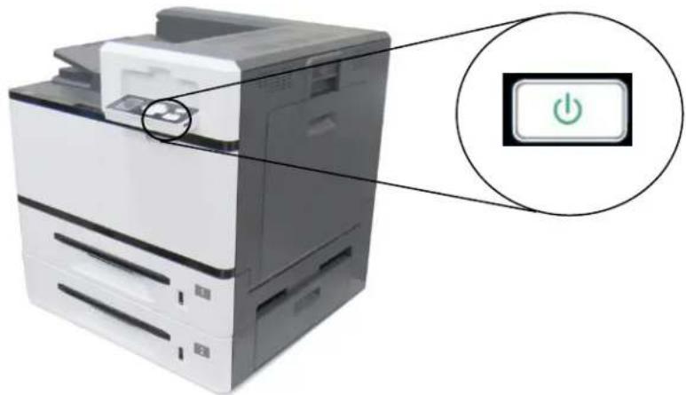
Turning On The Printer
To turn on the printer, short press the power button. To turn off the printer, long press the power button for at least 3 seconds.
natural_image
Exterior view of a printer with a power button icon (no text or symbols on the device itself)
Note:
When the product is not in use, be sure to turn off the power to get a zero power consumption state.
Connecting to the Network
Connect the printer to the network to use the network printing function.
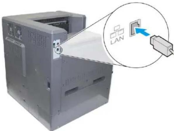
- Connect one end of your network cable to an available port of your Ethernet Hub.
- Connect the other end to the LAN port at the back of the product as shown.
natural_image
Computer printer with open lid and paper feed, showing a close-up of a device with a labeled 'LAN' icon (no text or symbols on the device itself)After the network cable is connected successfully, the IP address can be obtained automatically from the DHCP server.

Installing the Printer Driver
System Requirement
Windows 7, Windows 8, Windows 10, Windows 11
For USB Interface Users
Please follow these steps to install the printer driver if this machine is connected to your computer via a USB cable.

Important!
DO NOT connect the USB cable before installing the printer's driver.
- Insert the supplied CD into your CD-ROM drive. The installation menu appears.
- Click "Install Printer Driver" and follow the on-screen instructions to install the program.
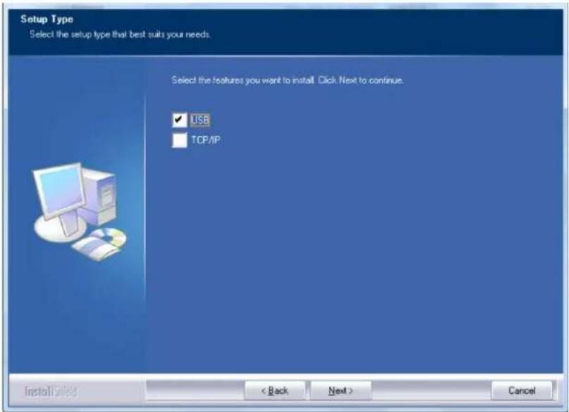
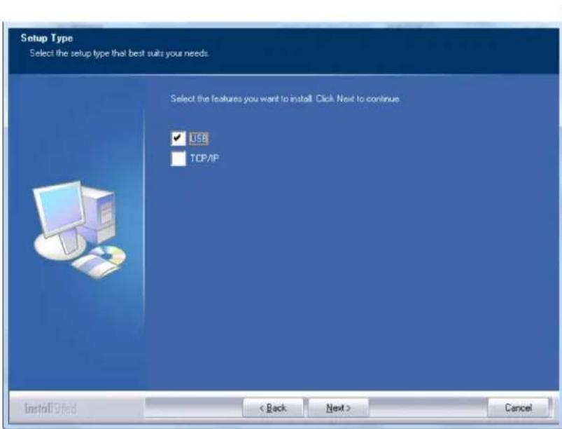
- When the Setup Type dialog box appears, select USB.
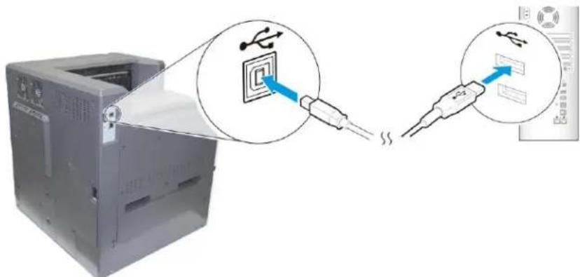
- During installation, the USB Connection dialog box will be prompted to instruct you to connect the machine to your computer with a USB cable.
a. Connect one end of the USB cable to your computer.
b. Connect the other end to the USB port of your product.
-
When the "Found New Hardware" screen appears, click Next and follow the on-screen instruction to complete the installation.
-
When the Finish dialog box appears, click Finish to complete.
If you have successfully installed the printer's driver, you will find a printer "AP400 Printer" has been added in the "Printers and Faxes" option from the Control Panel.
Uninstalling the Printer Driver
-
Make sure your USB cable is connected to your product.
-
From the "Start" menu, select "All Programs", the product model, and then "uninstall Driver".
For Network Interface Users
Please follow these steps to install the printer's driver if the printer is connected to your computer via a network cable.
-
Insert the supplied CD into your CD-ROM drive. The installation menu appears.
-
Click "Install Printer Driver" and follow the on-screen instructions to install the software.
-
When the Setup Type dialog box appears, select TCP/IP. If you need to connect the product to a network, check [USB] since the Network Setup Tool is included in the USB driver and only available when the product is connecting to your computer through the USB cable.
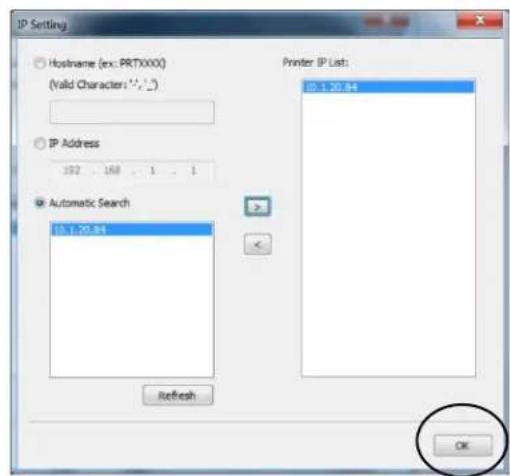
- When the following Set IP Address or Host Name dialog box appears, choose one of the following options. When the desired option setting is completed, click "OK".
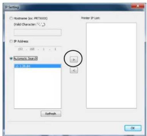
Host Name
Enter the product's host name to be connected in the blank box of the Host Name option.
To add more host names if more than one AP400 are connected in the network, click
"More" next to the Host Name box.
IP Address
Enter the product's IP address to be connected in the blank box of the IP Address option.
To add more IP Addresses if more than one AP400 are connected in the network, click "More" next to the IP Address box.
Automatic Search
Searches the product's printers automatically, and all the product's host names found in the network will be displayed in the box of the Automatic Search. Use your mouse to choose your desired host name to be connected.
- When the Finish dialog box appears, choose "Finish" to complete.
If you have successfully installed the printer driver, you will find a printer "AP400 NetWork Printer" has been added in the "Printers and Faxes" option from the Control Panel.
Changing the Product's IP Address in a Wired Network
To change the product's IP address, you need to install the Network Setup Tool. The Network Setup Tool is included in the USB printer driver. After the installation of the USB printer driver is completed, the Network Setup Tool is automatically installed onto your computer. Follow these steps to update the IP address to the product in a wired network.
You may also define your network connection via the web page. (See more details in the subsequent section Customize System's Settings via the Embedded Web Page in Chapter 3.
- Make sure the product is connected to your computer via a USB cable.
-
Start Network Setup Tool by choosing the Start button and then select All Programs>AP400 PRINTER>Network Setup Tool in succession. The following Network Setup Tool screen will be prompted.
-
On the [General] page, check [Wired (Ethernet)] Network to prompt the Wired (Ethernet) page.
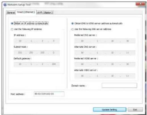
-
Check [Obtain an IP address automatically] to obtain the IP address directly from the DHCP server or you may enter your static IP on the [IP Address], [Subnet Mask], and [Gateway] field respectively.
-
If you have assigned a specific IP, enter your domain name server and WINS server as well and then click [Update Setting] to update the IP information to the product.
-
If update is successfully, an [Update Device Successfully] message will be displayed and the Network Setup Tool will be automatically closed.
3 Printing
Normal Printing
This section explains how to perform a normal print.
- In your computer, open the file you wish to print.
- Choose [Print] from the [File] option. The [Printing] dialog box will be displayed.
-
Choose this product from the printer list.
-
The default settings of this printer is as follows. Click [OK] to exit the [Print] dialog box if no need to change.
| Paper Size | A4 |
| Orientation | Portrait |
| Density | 3 |
| Tray | Auto Select |
| 1-Sided/2-Sided | Single-Side |
If you want to change the default settings, click [Properties] to prompt the [Printer Properties]dialog box. Modify your settings and then choose [OK] to exit the [Printer Properties] dialog box.
- Printing is started.
2-Sided Printing
This section explains how to print data on both sides of paper.
- In your computer, open the file you wish to print.
- Choose [Print] from the [File] option. The [Printing] dialog box will be displayed.
- Choose this product from the printer list.
- Click [Properties] to prompt the [Printer Properties]dialog box.
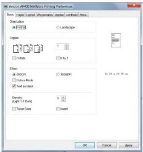
- Click the [Duplex] tab and then choose [Duplex]. Choice: Flip Horizontal, Flip Vertical.
| Flip Horizontal | Check to flip the duplex document on the left edge. 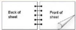 |
| Flip Vertical | Check to flip the duplex document on the bottom edge. 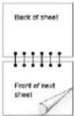 |
- Choose your duplex type and then click [OK] to exit the [Printer Properties] dialog box.
- Printing is started.
Combining Multiple Pages into One Sheet of Paper
This section explains how to print multiple pages into one single sheet of paper.
- In your computer, open the file you wish to print.
- Choose [Print] from the [File] option. The [Printing] dialog box will be displayed.
- Choose this product from the printer list.
- Click [Properties] to prompt the [Printer Properties]dialog box.
- Click the [Layout] tab and choose number of pages you wish to combine and your N-Up style.
| N-up: | Choose number of pages to be printed on a single sheet of paper.Choice: Off, 2up(2-in-1), 4-up(4-in-1), 9-up(9-in-1), 16-up(16-in-1)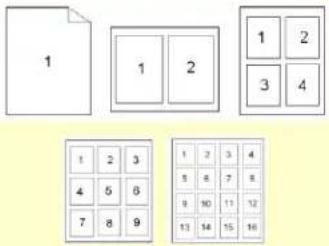 | ||
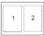
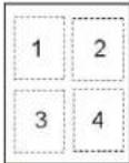
| Border: | Choose if you wish to add border around each page when printing more than one page on a single sheet of paper.Choice: None, Border Line, Dashed Line | ||
 |  |  | |
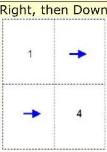
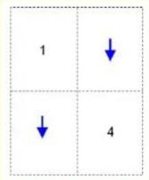
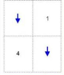
| N-up Style: | Choose the style you want when printing multi-page document on a single sheet.Choice: Right, then Down/Down, then Right/Left, then Down/Down, then Left | ||
Right, then Down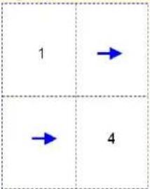 | Down, then Left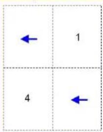 | ||
Down, then Right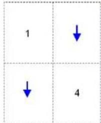 | Left, then Down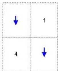 | ||
- Click [OK] to exit the [Printer Properties] dialog box.
- Printing is started.
Enhancing Your Print Quality
This section explains how to enhance your print quality. If the font size is small or the picture contains a variety of colors, choose this feature to improve your print quality.
-
In your computer, open the file you wish to print.
-
Choose [Print] from the [File] option. The [Printing] dialog box will be displayed.
-
Choose this product from the printer list.
-
Click [Properties] to prompt the [Printer Properties]dialog box.
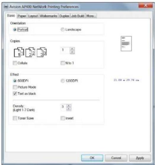
-
Choose 1200 dpi.
-
Click [OK] to exit the [Printer Properties] dialog box.
-
Printing is started.
More Printing Features
The Printing Preferences dialog box consists of the Basic tab, the Paper tab, the Layout tab, the Watermark tab, and the Duplex tab. More printing features of each tab will be explained in the following sections.
The Basic Tab
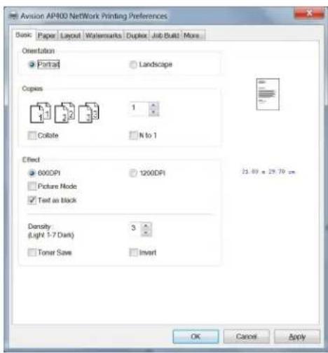
The Basic tab contains settings for Orientation, Copies, Effect, Density, Toner Save, and Invert.
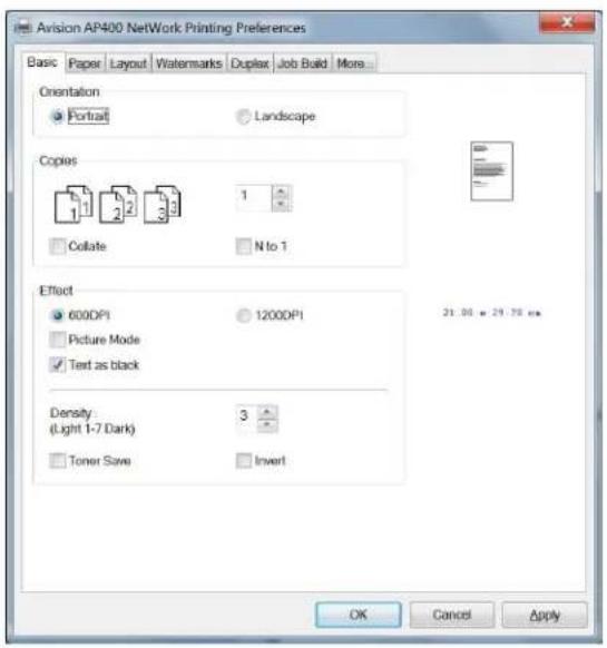
Orientation
Choose your orientation. Choice: Portrait, Landscape

Portrait
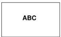
Landscape
Copies
Choose the number of copies to be printed. You can enter up to 999.
| Collate: | Click to print your document in the page order such as 1/2/3, 1/2/3, 1/2/3. 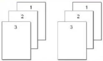 |
| N to 1: | Click to reverse the printing order of your document. As a result, the last page of your document will be printed first and vice versa. 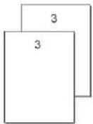  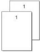 |
Effect
| 600 dpi | This option fits for most business document. |
| Quality Mode: | If the picture in your document does not print clearly, click Quality Mode to improve its quality. |
| Text as Black | Print colored text in solid black rather than shades of gray. |
| Density: | Click to lighten or darken your document. Density level (1~7). Default: 3 |
| Toner Save: | Allows you to print your document using the toner saving mode. |
| Invert: | Invert makes each image pixel inverted to its complementary color. For example: the original black text on white background becomes white text on black background. |
The Paper Tab
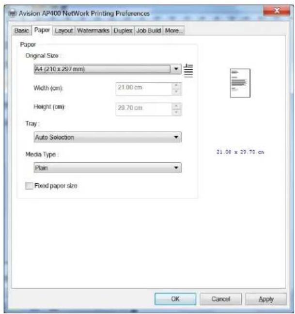
The Paper tab contains settings for Original Size, Tray, and Media Type.
Paper
| Original Size: | Choose the size of paper loaded in the designated tray.Choice: A3, A4, A5, B5, B4, *A6, *B6, Legal, *Legal 13, *Japanese PostCard, Letter, *Double Letter, *8K, *16K, *User Define*: Available for manual tray onlyA3: Not available for Main Tray |
| Tray: | Choose the tray from which your paper should be fed.Choice: Auto, Manual Tray, Main Tray, Tray 2Auto means automatically select the paper tray which matches the paper size of your document. |
| Media Type: | Choose the type of media to be used for printing.Choice: Plain Paper, Thin Paper, Thick Paper, Laser Paper, *Bond, *CardStock (Japanese PostCard), *Transparency*: Available for manual tray only |
| Fixed paper size: | Check to specify all output paper to the fixed paper size based on the Original Size option. |
The Layout Tab
The Layout tab contains settings for N-up, and Output Paper Size.

N-up
| N-up: | Choose number of pages to be printed on a single sheet of paper.Choice: Off, 2up(2-in-1), 4-up(4-in-1), 9-up(9-in-1), 16-up(16-in-1)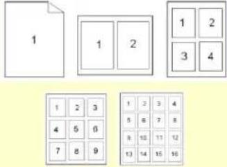 |
| Border: | Choose if you wish to add border around each page when printing more than one page on a single sheet of paper.Choice: None, Border Line, Dashed Line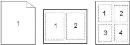 |
N-up Style:
Choose the style you want when printing multi-page document on a single sheet.
Choice: Right, then Down/Down, then Right/Left, then Down/Down, then Left
 |  |
| Down, then Right | Left, then Down |
 |  |
Output Paper Size
| User Define Scale | You can reduce or enlarge your printed image using the Slider Bar. Scaling rate: 25%~400% |
| Fit to Paper | Output the full page of the selected original including the four margins. |
| Center | Print your image in the center of the output paper. |
The Watermark Tab
The Watermark tab allows you to add some text or image (such as CONFIDENTIAL, IMPORTANT, DRAFT, etc) for your document.
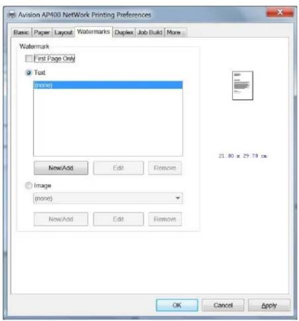
| First Page only | Check to print watermark only on the first page. Clear the check box will print watermark on all pages. |
| Text | Choose and click New/Add to add new watermark text. Click the Edit button to change or the Remove button to delete.  |
| Image | Choose and click New/Add to add watermark image. Click the Edit button to change or the Remove button to delete. You can choose your image in file format such as BMP, TIFF, or JPEG. |
Adding a new waterk text
To add a new watermark text,
- Choose Text and then click the Add/New button. The following Add a new Watermark dialog box appears.
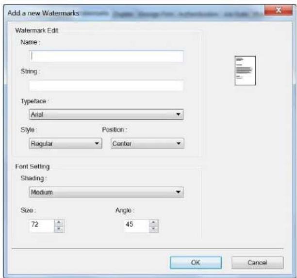
| Name | Name your watermark text. This name will be shown in the Watermark text list. |
| String | Enter your watermark text, such as confidential, important, and so on. |
| Typeface | Choose your font type for your watermark text. |
| Style | Choose the style of your watermark text.Choice: Regular, Bold, Italic, Bold Italic. |
| Position | Choose the position of your watermark text.Choice: Center, Tile. |
| Angle | Specify the angle of the watermark text from 0° to 360° |
| Size | Specify the size of your watermark text from 1 to 288. |
| Shading | Specify a relative density for the watermark text.Choice: Lightest, Light, Medium, Dark, Darkest. |
- Click the OK button to save the settings. If the new watermark text is created successfully, the watermark name will be shown in the Text list.
Editing a current watermark text
To edit a current watermark text,
-
Choose the watermark name that you wish to edit from the Text list.
-
Click the Edit button. The Watermark Edit dialog box appears.
-
Change your settings for the selected watermark text and choose OK to complete.
Removing a current watermark text
To remove a current watermark text,
-
Choose the watermark name that you wish to remove from the Text list.
-
Click the Remove button. The watermark text will be removed.
Adding a new waterk image
To add a new watermark image,
- Choose Image and then click the Add/New button. The following Watermark dialog box appears.
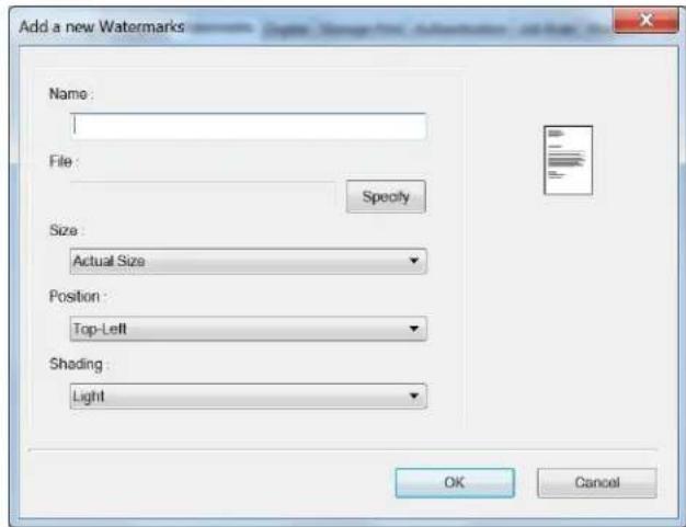
| Name | Name your watermark image. This name will be shown in the Watermark image list. |
| File | Click the Browse button to locate your watermark image. |
| Size | Specify the size of your watermark image. Choice: Actural Size, Fit to Page, Tile. |
| Position | Choose the position of your watermark image. Choice: Top-Left, Top-Center, Top-Right, Center, Center-Left, Center-Right, Bottom-Center, Bottom-Right, Bottom-Left. |
| Shading | Specify a relative density for the watermark text. Choice: Lightest, Light, Medium, Dark, Darkest. |
- Click the OK button to save the settings. If the new watermark image is created successfully, the watermark name will be shown in the Image list.
Editing a current watermark image
To edit a current watermark image,
- Choose the watermark name that you wish to edit from the Image list.
- Click the Edit button. The Watermark Edit dialog box appears.
- Change your settings for the selected watermark image and choose OK to complete.
Removing a current watermark Image
To remove a current watermark image,
- Choose the watermark name that you wish to remove from the Image list.
- Click the Remove button. The watermark image will be removed.
The Duplex Tab
The Duplex tab allows you to print your document on two sides of the paper.
Choice: Long Edge, Short Edge, Booklet
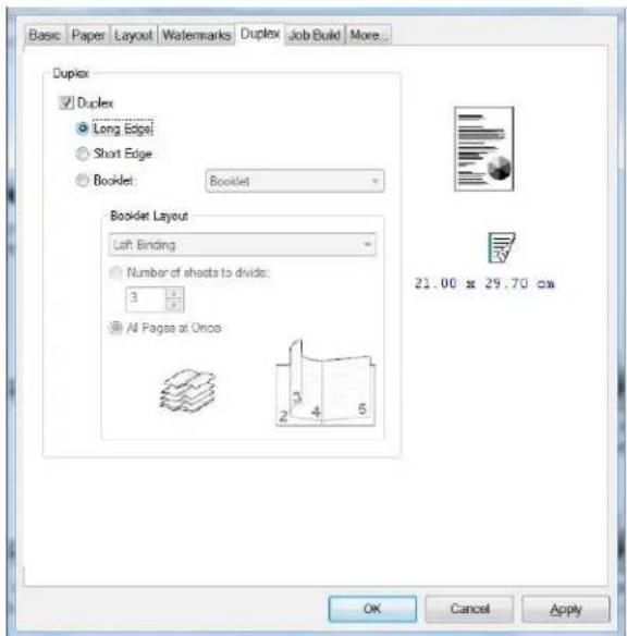
When using Two-Sided printing, you can select whether to bind copies on the long-edge or short-edge.
| Long Edge (Binding) | Long-Edge binding (Portrait) will print the pages so that you flip them like you would do on a book. | |
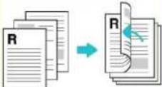 Long-Edge binding (Portrait) Long-Edge binding (Portrait) |  Long-Edge binding (Landscape) Long-Edge binding (Landscape) | |
| Short Edge (Binding) | Short-Edge binding (Portrait) prints them so that your flip them like you would do on a calendar. | |
 Short-Edge binding (Portrait) Short-Edge binding (Portrait) |  Short-Edge binding (Landscape) Short-Edge binding (Landscape) | |
Booklet
Booklet (No Reduction)
The feature allows you to print your documents as a booklet. Choose 「Booklet」, the contents of the file will be automatically reduced to fit your output paper. Choose 「Booklet (No Reduction)」, the contents of the file will be kept the same with the output paper.
For example, to print an A4-sized document to an A4-sized booklet, choose 「Booklet (No Reduction)」, the product will automatically choose output paper to be A3 size to keep the original size.
On the other hand, if you wish to print an A4-sized document to an A5-sized booklet, choose 「Booklet」, the contents of the document will be reduced to fit your output paper.
Booklet Layout:
Portrait Orientation
Left Binding/Right Binding: Select Left Binding or Right Binding for your booklet printing.
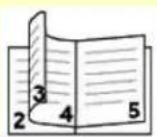
Left Binding
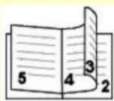
Right Binding
Landscape Orientation
Top Binding/Bottom Binding: Select Top Binding or Bottom Binding for your booklet printing.
A booklet is a document which is printed in a way that when you fold the printed pages in the middle and staple them, the pages will be in correct order as a book would be.
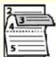
Top Binding
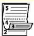
Bottom Binding
| Booklet Booklet (No Reduction) | Number of sheet to divide/All Pages at Once: Check [Number of sheet to divide] to separate your pages into sets and press the Arrow key to enter number of pages. All Pages at Once: Check [All Pages at Once] to print all pages in one set. | |
 |  | |
| Number of sheet to divide: 2 | All Pages at Once | |
The Job Build Tab
The Job Build tab allows you to combine multiple types of files into a cohesive single file and to print them together from your PC.
For some cases, it is time-consuming and labor-intensive to manually combine and print certain pages from multiple documents such as a picture file from an image editing software and a text document from a word-processing software. Enabling the Job Build function allows you to do this in just a single file.
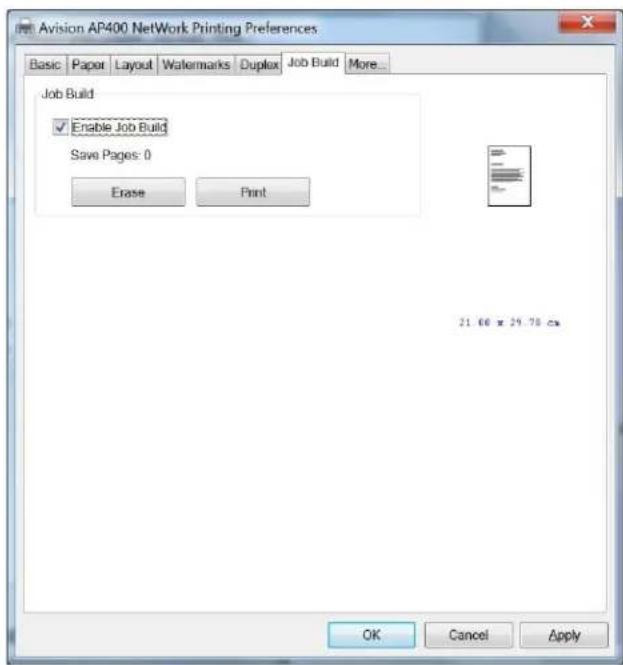
| Enable Job Build | Check to enable the Job Build function.Each time you perform printing your file, a print job for the file is temporarily stored in your PC memory. |
| Click to print the single combined file for all of your print jobs stored in your PC. | |
| Erase | Click to erase all of your print jobs temporarily stored in your PC |
The More Tab
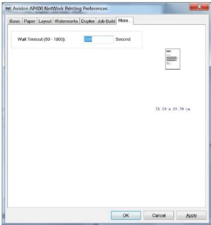
On the More tab, a Wait Timeout option is provided to set the amount of time the printer waits for data to come from computer during a job. If the data stream pauses for longer than the specified number of seconds, the job is cancelled.
Permitted timeout values: 60\~1800 seconds, default timeout values: 300 seconds
4 Configuring the Machine
This product is designed to be ready to use with the default settings. However, if desired, you can change the settings to meet your specific needs. To change the default settings, press the "menu" button on the control panel or go to the product's embedded web page. How to customize the product's configurations via these two methods will be described in the following sections.

Note:
When installing the product for the first time, it is recommended that the Administrator retain the default system settings. The settings can be customized at a later date once you are familiar with the operation and functionality.
Customizing System's Settings via the Control Panel
To change the default settings on the control panel, press the "menu" button on the control panel. The menu information will be displayed. To navigate the menu items, the OK, Up, Down, and Back buttons are provided on the control panel. You can adjust settings (e.g. set the paper size for Tray 1) or view information (e.g. IP address, firmware version).
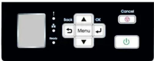
Typical steps in using the menus are as follows:
- Press the Menu button to access the menu items.
- Press the ▲Up /▼Down buttons repeatedly until the desired menu is highlighted in the displayed list.
- Press the OK button to select this menu.
- Press the ▲Up/▼Down buttons repeatedly until the desired item is highlighted.
- Press the OK button to select this item.
- Press the Back button to go back to the previous screen.
- Press the Cancel button to leave the menu item.
Menu Items on the LCD Screen
Network
*Factory Default Settings
| Item | Description | Choice | |
| Network | Wi-Fi: Choose to turn on or off Wi-Fi connection.Choice: Wi-Fi/Wi-Fi WPS Button/Direct Link | Wi-Fi/Wi-Fi WPS Button/ Network Filter | |
| On | Turn on Wi-Fi and enter Wi-Fi Station Mode.Please go to the product's web page to select a wireless network (SSID). | ||
| Direct Link | Turn on Wi-Fi and go to Wi-Fi AP (Access Point mode. The product is now an Wi-Fi AP itself. | ||
| Wi-Fi WPS Button: You may connect the device to a WPS compatible wireless access point by selecting [Wi-Fi WPS button]. To enable the WPS connection of your access point, please refer to the user's guide of your access point.Network Filter: Specify if you wish to enable or disable the Network filter configuration. Once enabled, your can specify the filter mode to allow some IPs to access the device or deny some IPs from accessing the device via the product's embedded web page.Choice: Enable/*Disable | |||
System Status
*Factory Default Settings
| Item | Description | Choice |
| Language | Choose the language you wish to display on the LCD panel. | *English,繁體中文,簡体中文 |
| Input Tray | ||
| Paper Size Confirmation | If on is selected, each time when the tray has been opened, a dialog box will be prompted to let users confirm the paper size and orientation in tray. | On/*Off |
| Paper Configuration | When [Auto] is selected for Paper Size option, choose ISO201 or North America when paper size is Letter or A4. | *ISO201/North America |
| Manual Tray | ||
| Paper Size | Specify the available paper size and orientation on the manual tray. | A3 SEF B4 SEF A4 SEF *A4 LEF B5 SEF A5 SEF LGL SEF LG 13 SEF LTR SEF LTR LEF DLT SEF A6 SEF B6 SEF 8K SEF 16K SEF PT SEF Custom Size |
| Media Type | Specify the media type in the manual tray. | Any type, Plain paper, thin paper, thick paper, laser printer, bond, cardstock, transparency |
| Tray 1 | ||
| Paper Size | The available paper size and orientation on the Tray 1 (Main Input Tray).Auto: Automatically detect paper size and orientation. | *AutoB4 SEFA4 SEFA4 LEFB5 SEFB5 LEFA5 SEFLGL SEFLTR SEFLTR LEF |
| Media Type | Specify the media type in tray 1. | Any type, Plain paper, thin paper, thick paper, laser printer |
| Tray 2 | ||
| Paper Size | The available paper size and orientation on Tray 2.Auto: Automatically detect paper size and orientation. | *AutoB4 SEFA4 SEFA4 LEFB5 SEFB5 LEFA5 SEFLGL SEFLTR SEFLTR LEF |
| Media Type | Specify the media type in tray 1. | Any type, Plain paper, thin paper, thick paper, laser printer |
| Sleep Mode | Choose how long to enter the sleep mode after your last action.ECO Mode: 5 seconds after theaction, the machine will enter ECO mode. Press the Power button to wake up the machine yet it takes a few minutes due to initialization first. | *ECO Mode, 5Min, 15Min, 30Min, 1Hr, 2Hr, 4Hr |
| Auto Power Off | Choose how long to enter the Auto Power Off mode after the sleep mode expires. | 5Min, 15Min, 30Min, 1Hr, 2Hr, 4Hr, *Off |
| Management | Press Reset Default to return to factory default settings.Developing Unitinitialization: Press this option after a new EP has been installed. | *Reset Default,Developing Unitinitialization |
| Heater | Turn on the heater and specify the humidity level of the sensor to keep the inside of the printer operate in the correct environment. | *Off/RH 80%/RH 70%/RH60%/RH 50%/On |
*: Factory Default Setting
Report
Press [Report] and the printer will automatically print the following usage report.
| Item | Description |
| Configuration | The configuration of this machine. |
| Menu Map | All the menu items and their choices in the LCD-display. |
| Usage Report | The usage report including total page count and the supplies status of toner, fuser, and EP. |
| Network | The network information. |
Information
Choose this item and the basic information including host name, IP address, LAN MAC address, firmware version, and machine S/N.
Customize System's Settings via the Embedded Web Page
Note: Any update of the web page requires administrator's login.
You may choose your network connection type through the webpage.
-
Obtain the product's IP address by pressing the [Menu] key and select [Information]>[IP Address]. The IP address will be displayed.
-
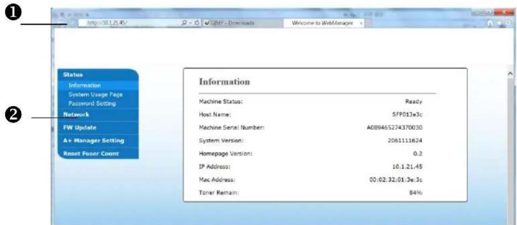
Open your browser and type the product's IP address on the URL address ①, for example, http://10.1.20.80 and press Enter. In a second, the embedded web page will be displayed ②.
- Enter your desired setting on your selected items.
Setting Items on the Webpage
Status
Displays the status and basic information of the product.
| Item | Description |
| Information | |
| Machine Status | Displays the machine status. |
| Host Name | Displays the host name. |
| Machine SN | Displays the machine's series number. |
| System Version | Displays the firmware version. |
| GDI Version | Displays the GDI version. |
| Homepage Version | Displays the version of the embedded web page. |
| IP Address | Displays the IP address. |
| Mac Address | Displays the Mac address. |
| Toner Remain | Displays the toner remain of the toner cartridge. |
| System Usage Page | Download the usage page to print the usage report including page count, toner cartridge, and drum unit. |
System Settings
Displays the system settings of the product.
* Default Settings
| Item | Description | Choice |
| Date (yyyy-mm-dd): | Display current date for the machine. | |
| Time (hr:min): | Display current time for the machine. | |
| Language | Choose the language you wish to display on the LCD panel. | *English, 繁體中文, 簡体中文 |
| Sleep Mode | Choose how long to enter the sleep mode after your last action. ECO Mode: 5 seconds after theaction, the machine will enter ECO mode. Press the Power button to wake up the machine yet it takes a few minutes due to initialization first. | ECO Mode, 5Min, *15Min, 30Min, 1Hr, 2Hr, 4Hr |
| Auto Off | Choose how long to enter the Auto Power Off mode after the sleep mode expires. | 5Min, 15Min, *30Min, 1Hr, 2Hr, 4Hr, Off |
| Management | ||
| Factory Default | Press [Reset Default] to resume factory default settings. | |
| Password Settings | ||
| New Password | Enter password to revise data on the webpage. (default: 12345678) Your password must be 8~16 characters including letters or numbers. | |
| Retype Password | Retype to confirm your password. | |
Network
*Default setting
| Item | Description | |
| Host Name | ||
| Host Name | Shows the host name. | |
| Ethernet Setting | ||
| Obtain an IP automatically | *ON, OFF | |
| IP Address | Enter the IP address of this machine. | |
| Subnet Mask | Enter the subnet mask. | |
| Gateway | Enter the gateway IP. | |
| Auto-Obtain WINS/DNS Server | *ON, OFF | |
| Preferred DNS Server | Specify the IP address of the Primary DNS Server. | |
| Alternate DNS Server | Specify the IP address of the Secondary DNS Server. | |
| Preferred WINS Server | Specify the IP address of the Primary Wins Server. | |
| Alternate WINS Server | Specify the IP address of the Secondary Wins Server. | |
| Domain Name | Specify the domain name. | |
| Wi-Fi Settings | ||
| Search AP | Select an available Access Point (AP). | |
| IP Setting | Specify a static IP or obtain it automatically. | |
| Network Security Settings | ||
| Security Configuration Filter | Specify if you wish to enable or disable the filter configuration. | *Disable/Enable |
| Filter Mode | Specify your filter mode to allow some IPs to access the device or deny some IPs from accessing the device's embedded web page. | Allow/Deny |
| IP Address Filter Configuration | IP Address Filter Configuration- Four types of Start IP and End IP can be specified.Mac Address Filter Configuration- Up to 10 Mac address can be specified. | IP Address Filter Configuration/Mac Address Filter Configuration |
FW Update
- To update firmware,
- Download the latest firmware from the web site or distributor.
- Open your browser and enter the IP address of the printer on the URL address.
- Open the webpage.
- Choose [FW Update] and then [Browse] to select the firmware file.
- Choose [Update] to complete.
A ^+ Manager Setting
Enter the IP address of a specified server to send the system log file to for quick troubleshooting.
Reset Fuser Count
Make sure to enter zero and then choose [Update] after a new fuser has been installed to reset the fuser count.
5 Troubleshooting
Monitoring Your Printer Using Printer Status Monitor
Printer Status Monitor allows you to monitor your printer's status, get information on consumable parts, and alerts you when printer errors occur.
Printer Status Monitor is available when the printer is connected directly to a host computer via the USB port or a network port. Printer Status Monitor is installed when you install the printer driver as described in the preceding section.
Accessing Printer Status Monitor
Double-click the Printer Status Monitor icon on the system tray. The following printer status window appears.
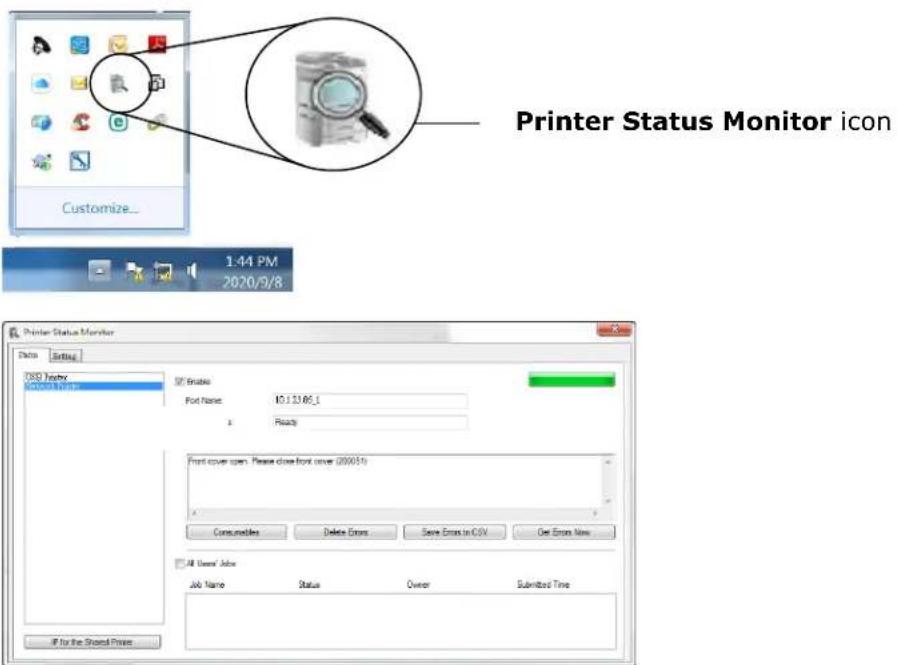
Printer Status Window
Getting Printer Status Details
You can monitor printer status and get information on consumable products using the Printer Status Monitor dialog box.
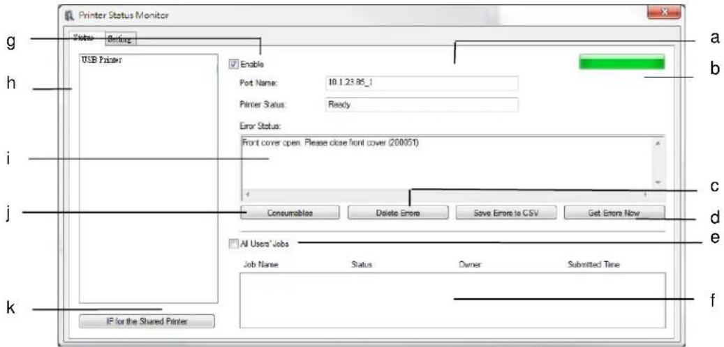
| a Port Name | Port name for the specified printer |
| b Progress Bar | The progress bar to access the latest data of the specified printer. |
| c Delete Errors | Delete all the error messages. |
| d Save Errors to CSV | Save error message to a CSV file. |
| e All Users' Jobs | Check the box to show All users' jobs. |
| f Job Box | Show all the jobs in queue. |
| g Enable | Check the box to enable accessing the status of a specified printer. |
| h Printer | Displays the connected printers. |
| i Text Box | Displays the current status of the printer. |
| J Consumables | Click to show the information of the paper tray and the consumables parts such as Drum, Toner. |
| k IP for a Shared Printer | Click here to enter the IP for a shared printer to get the printer status. |
Setting Monitoring Preferences
To make specific monitoring settings, click the Setting tab on the Avision Status Monitor window.
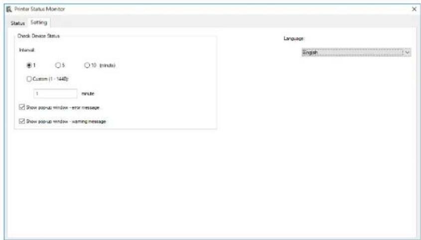
| Language | Displays the language of the window. |
| Status Alert | |
| Update Time | Define the interval to refresh the printer error status.Choice: 1, 5, 10 (minute), Custom (1 ~ 1440) minute |
| Show pop-up Window- error message | Check this box to show the error message. |
| Show pop-up window-warning message | Check this box to show the warning message. |
Clearing A Warning or Error Message
If a problem occurs during operation, a warning or error message will display on the LCD panel. In addition, the Error LED will be flashing or solidly lit to indicate a warning or an error status. To solve the problem, please follow the on-screen instruction or the following table for more detailed information.
| 200030 | No toner cartridge. | Please install a toner cartridge. |
| 200031 | Toner empty | Replace toner cartridge with a new one. |
| 200032 | Low toner (remaining toner less than 10%) | Replace toner cartridge with a new one. |
| 200033 | No waste toner can. | Install a waste toner can. |
| 200034 | Waste toner can is full. | Replace with a waste toner can. |
| 200035 | Waste toner can near full. | Prepare to order a new waste toner can from a nearest distributor. |
| 200036 | Toner cartridge error. (a toner cartridge supplied not from the original manufacturer has been detected). | Instsall a toner cartridge from the original manufacturerer. |
| 200040 | EP sensor fails. | 1.Restart the machine.2.If the error persists, call service. |
| 200041 | No EP. | Install EP. |
| 200042 | EP lifetime ends. | Replace with a new EP. |
| 200043 | EP lifetime is near end. (Remaining lifetime less than 10%) | Prepare to order a new EP from a nearest distributor. |
| 200044 | Invalid EP. EP does not supply from the original manufacturer or serial number incorrect. | Replace the EP from the original manufacturer and with correct serial number. |
| 200141 | No drum.Install drum | Install a drum. |
| 200142 | Drum lifetime endReplace drum | Replace drum. |
| 200143 | Drum lifetime near end: (Remaining lifetimeless than 10%) | Replace drum. |
| 200144 | Invalid drum. Wrong drum manufacturer of incorrect serial number. | Please install the drum from original manufacturer. |
| 201502201512 | Invalid fuser. Please install the fuser from original manufacturer. | Please install the fuser from original manufacturer. |
| 201503201513 | Invalid developer unit. Please install the developer unit from original manufacturer. | Please install the developer unit from original manufacturer. |
| 201504201514 | Invalid drum. Please install the drum from original manufacturer. | Please install the drum from original manufacturer. |
| 201505201515 | Invalid toner cartridge. Please install the toner cartridge from original manufacturer. | Please install toner cartridge from original manufacturer. |
| 201611 | Toner empty (toner capacity sensor has been detected off.) | Replace toner cartridge with a new one. |
| 201619 | Fuser lifetime ends. | Replace with a new fuser. |
| 201620 | Fuser lifetime is near end. (Remaining lifetime less than 10%) | Prepare to order a new fuser from a nearest distributor. |
PaperJam Errors
When paperjam error occurs, check the jammed positions indicated in the message to clear the jam error.

Notice when removing the jammed paper:
- As shown in the figure below, gently remove the paper by holding the edges of paper with both hands according to the arrow direction. Removing jammed paper by force in other directions (up, right, or left) might cause damage to the machine.

natural_image
Close-up of hands installing or adjusting electronic equipment in a server rack (no visible text or symbols)- Check if the paper is complete. If it is incomplete, check if any scraps left inside the machine and remove the scraps. Otherwise, the scraps might affect document feeding and also the print quality.
Paperjam Areas
Area A: Fuser
Area B: Paper Exit on Tray 1
Area C: Duplex Unit
Area D: Side Cover of Tray 2
Area E: Side Cover of Tray 3
Area F: Drum Unit

| Error Code | Cause | Solution |
| 200301 | Paperjam in the manual tray | 1. Remove the jammed paper. Fan your paper and reload it to the manual tray.2. If the problem still persists, clean the Feeding Roller in the manual tray. |
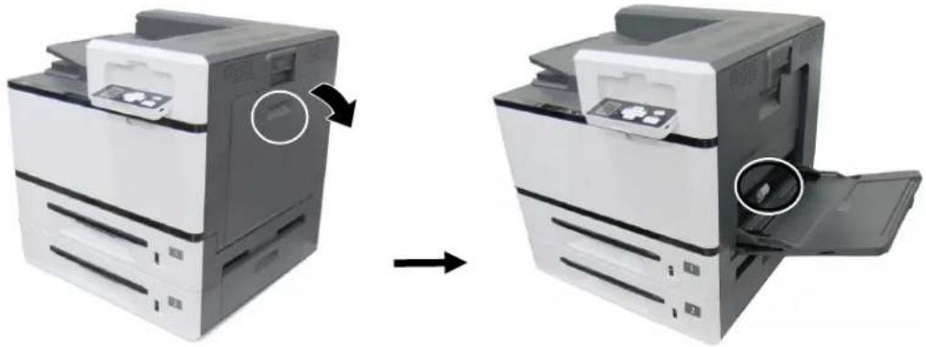 | ||
| Error Code | Cause | Solution |
| 200302 | Paperjam in Tray 1 | 1. Open the Side Door.2. Check if there is jammed paper in the paper exit of Tray 1 (Area B). If so, remove the paper.3. Open Tray 1 to remove the jammed paper.4. Close Tray 1 and the Side Door. |
 | ||
| 200303 | Paperjam in Tray 2 | 1. Open the Side Door of Tray 2 as shown.2. If there is paper on Area D (paper exit on Tray 2), remove the paper.3. Open Tray 2 to remove if there is further paper.4. Close Tray 2 and the Side Door of Tray 2. |
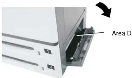 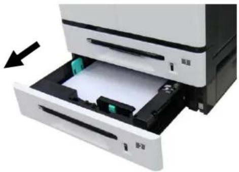 | ||
| 200306 | Paperjam in deskew sensor。 | 1. Open the Side Door.2. If there is paper on Area B (paper exit on Tray 1), remove it. Be careful not to touch the area marked the temperature.3. Close the Side Door. |
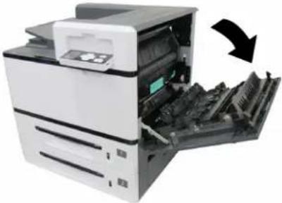  | ||
| Error Code | Cause | Solution |
| 200309 | Paperjam in paper exit sensor of fuser. | 1. Turn off the machine and wait for a few minutes to let the operating temperature drop and then open the Side Door.2. Check Area A (Fuser area) and remove the paper. Pay attention the temperature is high in the fuser.3. Close the fuser cover and the Side Door. |
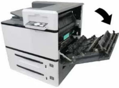 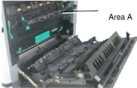 | ||
| 200317 | Paperjam in Tray 3 | 1. Open the Side Door of the 3^rd and 4^th Tray.2. If there is paper in the exit of the 3^rd Tray, pull the paper out a bit and then remove the paper.3. If there is no paper in the exit of the 3^rd Tray, open Tray 3 to remove paper. Then close Tray 3.4. Close the Side Door of the 3^rd and 4^th Tray. |
| Error Code | Cause | Solution |
| 200318 | Paperjam in Tray 4 | 1. Open the Side Door of the 3^rd and 4^th Tray.2. If there is paper in the exit of the 3^rd Tray, pull the paper out a bit and then remove the paper.3. If there is no paper in the exit of the 3^rd Tray, open Tray 3 to remove paper. Then close Tray 3.4. Close the Side Door of the 3^rd and 4^th Tray. |
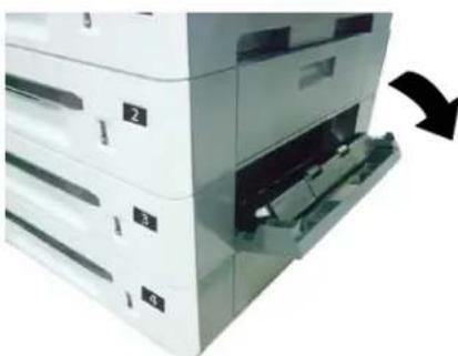 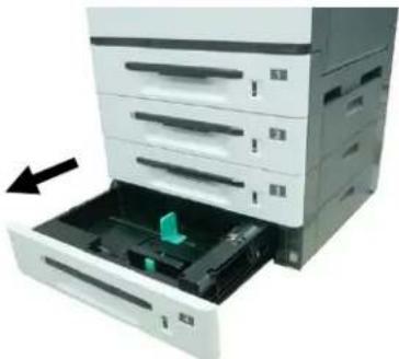 | ||
| 200340 | Paperjam in the sensor of Tray 1 | 1. Open the Side Door.2. If there is paper on Area B (paper exit on Tray 1), remove it. The temperature near the fuser is very high.Do not touch those areas.3. Close the Side Door. |
| 200341 | Paperjam between Tray 1 Sensor and Deskew Sensor | Same as above |
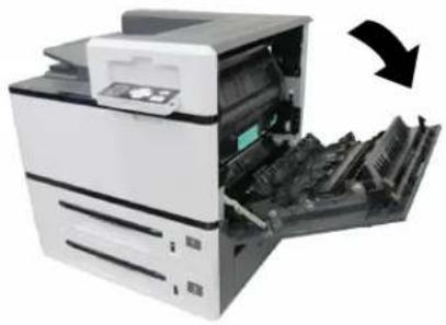 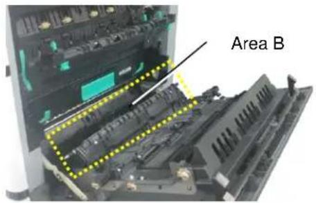 | ||
| 200342 | Paperjam in Tray 2 | 1. Open the Side Door.2. If there is paper on Paper Exit of Tray 2, pull the paper out and then remove it.3.If there is no paper on Paper Exit of Tray 2, pull out Tray 2 to remove the paper.4.Close Side Door and Tray 2. |
| 200343 | Paperjam between Tray 1 sensor and Tray 2 sensor | Same as above |
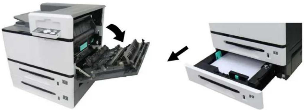 | ||
| 200344 | Paperjam in Tray 3 sensor | 1. Open the Side Door of Tray 2.2. If there is paper on Area D (paper exit of Tray 2), pull the paper out and remove it.3. If there is no paper, pull Tray 3 to remove all paper.4. Close the Side Door of Tray 2. |
| 200345 | Paperjam between Tray 2 sensor and Tray 3 sensor | Save as above |
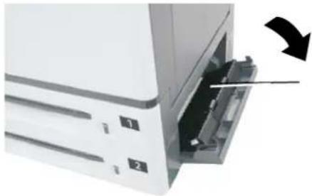 Area D Area D | ||
| 200346 | Paperjam in Tray 4 sensor | 1.Open the Side Door of Tray 3.2.If there is paper on Area E (Paper exit of Tray 3), pull the paper out and then remove the paper.3.If no paper, open Tray 3 to check and remove paper.4.Close the Side Door of Tray 3 and Tray 3. |
| 200347 | Paperjam between Tray 3 sensor and Tray 4 sensor | Same as above |
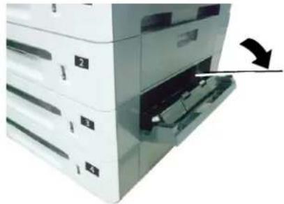 Area E Area E | ||
| 200348 | Paperjam in the Duplex Unit | 1. Open the Side Door of the Duplex Unit.2. If there is paper in area C (Duplex Unit), pull the papergently and remove the paper.3. If the problem repeats, please clean the pickup rollers of the Duplex Unit. |
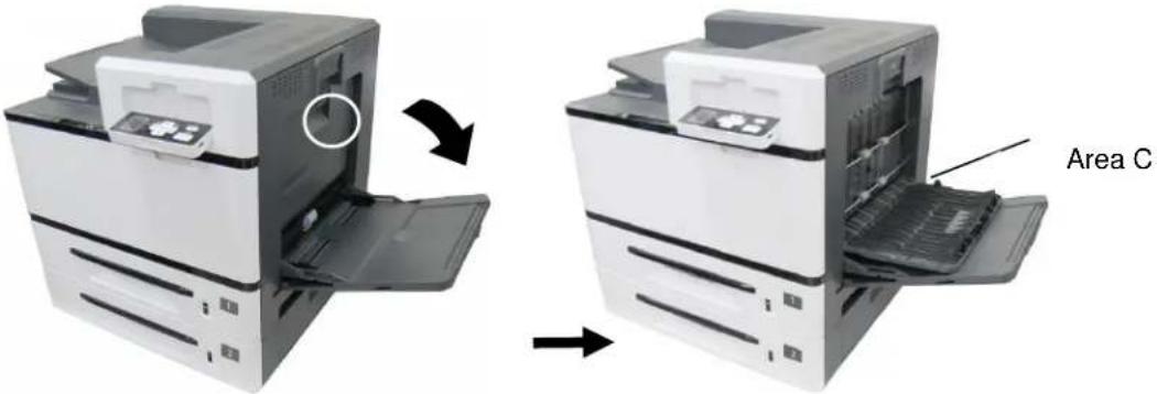 | ||
| Error Code | Cause | Solution |
| 200349 | Paperjam in Duplex Sensor and Deskew Sesnor | 1. Open the Side Door of the Duplex Unit.2. If there is paper in area B and area C (Tray 1 exit, Duplex unit), remove the paper. Be careful not to touch the places marked high temperature.2. If the problem persists, clean the pickup roller of the Duplex Unit. |
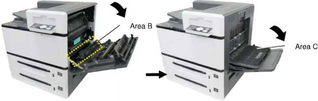 | ||
| 200351 | Paperjam between Fuser Sensor and Duplex Sensor | 1. Open the Side Door of the Duplex Unit.2. If there is paper in area C (Duplex Unit), pull the papergently and remove the paper.3. If the problem repeats, please clean the pickup rollers of the Duplex Unit. |
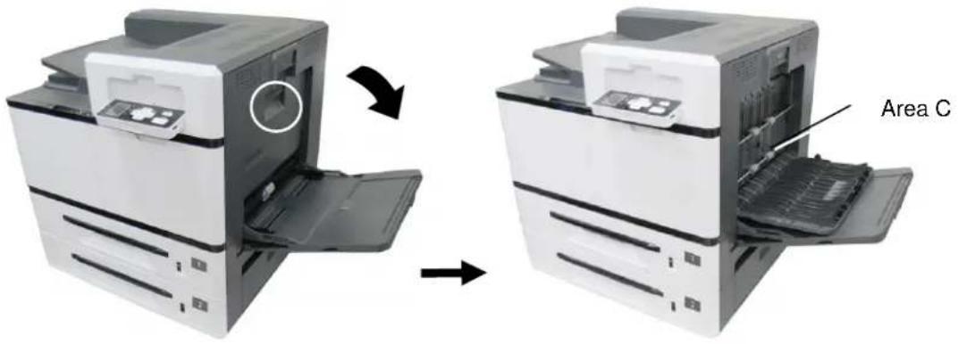 | ||
| 200352 | Paperjam between Deskew Sensor and Drum Jam Sensor | 1. Open Side Door.2. Remove the drum unit and check area F. Remove paper. Be careful not to touch the places marked high temperature.3. Close Side Door and Manual Tray Side Door. |
| 200353 | Paperjam in Drum Jam Sensor | |
| 200354 | Paperjam between Drum Jam Sensor and Fuser Out Sensor | |
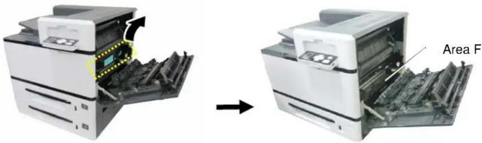 | ||
How to remove the jammed paper in the drum unit
- Open the Side Door and remove the drum unit as shown.
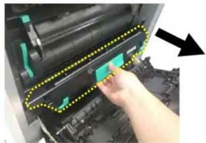
natural_image
Close-up of a hand pressing down on a printer's door panel with a yellow dotted line and green control bands (no text or symbols visible)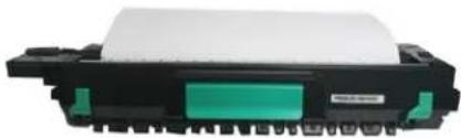
natural_image
Exterior view of a black rectangular electronic component with a green internal slot and white top (no visible text or symbols)- Release the roller by pressing down the Release Arms on two ends and then
gently remove the paper.
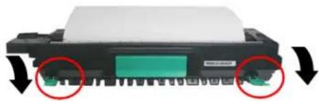
natural_image
Close-up of a black electronic component with green and red circular annotations indicating directional changes (no text or symbols)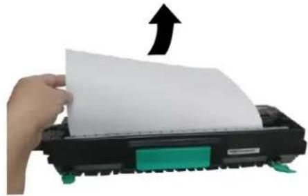
natural_image
Hand pressing down on a paper printer with an arrow indicating upward motion (no text or symbols visible)- After removing the paper, pull up the Release Arms on both ends. Then grapse the handle of the drum unit and install it horizontally to the original place in the printer as shown.
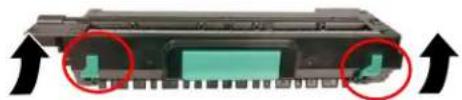
natural_image
Close-up of a black electronic component with green indicator lights and red circular annotations (no readable text or symbols)
natural_image
Close-up of a hand inserting a green component into a machine, with arrows indicating the process (no visible text or symbols)How to remove the jammed paper in the fuser
- Open the Side Door. Release the fuser by pressing down two lock hooks on both sides as shown.
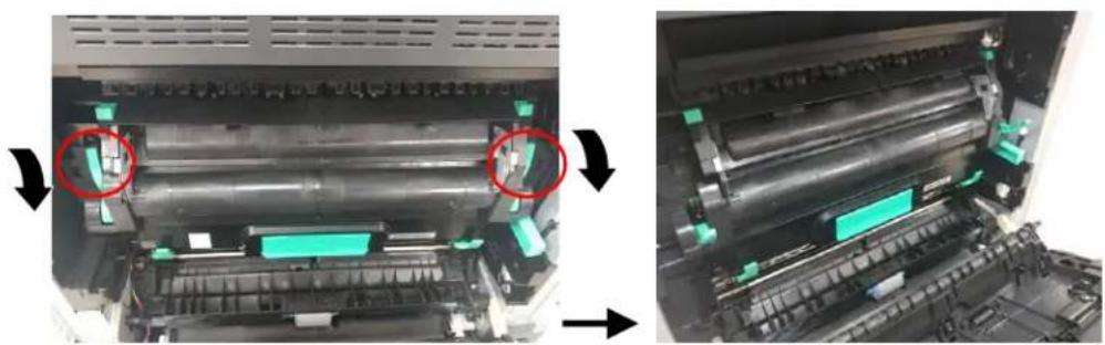
natural_image
Two views of a printer's internal mechanism showing mechanical components and assembly (no visible text or symbols)- Open the fuser cover by pressing down two lock tabs on the top. Gently remove the jammed paper.
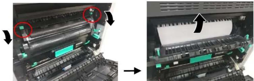
natural_image
Close-up of a printer's internal structure showing roller rollers and green components, with arrows indicating motion direction (no text or symbols visible)- After the jammed paper has been removed, close the fuser cover. A snap-in sound will be heared.

natural_image
Interior view of a server rack with highlighted circuit breakers and a black arrow indicating direction (no text or symbols)- Finally, push the lock hooks back into its original places as shown. Then close the Side Door.
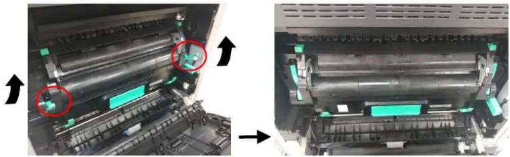
natural_image
Close-up of a printer's internal mechanism showing blade assembly and green component placement (no text or symbols visible)Fuser Errors
| Error Code | Problem Cause on Fuser | Solution |
| 201600 | A3 or A4 lamp heating exceeds the upper temperature limit (210 degrees). | 1. Reboot the machine.2. If the error code persists, replace the fuser. |
| 201604 | Analog to Digital conversion (ADC) adjustment not ready. | |
| 201605 | Analog to digital conversion not ready: In a non-initial state, query on the A3 and A4 lamps' ADC values per 500ms fails. | |
| 201607 | The temperature difference between A3 and A4 lamps is more than 50 degrees. | |
| 201612 | The difference between the current and last temperatures of the A3 lamp is more than 20 degrees. | |
| 201613 | The difference between the current and last temperatures of the A4 lamp is more than 20 degrees. | |
| 201614 | In the warming state, the A3 lamp does not heat up over 5 degrees in 10 seconds, which means a heating error occurs. | |
| 201615 | In the warming state, the A4 lamp does not heat up over 7 degrees in 10 seconds, which means a heating error occurs. | |
| 201616 | Fuser heating from ready to print status is over 20 seconds. | |
| 201617 | Fuser heating from warming to ready status is over 155 seconds. | |
| 201618 | Fuser heating from starting to ready status is over 100 seconds. | |
| 201621 | The machine detects that the A4 lamp's thermistor is not connected. | |
| 201622 | The machine detects that the A3 lamp's thermistor is not connected. | |
| 201630 | The machine detects that the environmental thermistor is not connected. |
Runtime Errors
| Error Code | Problem Cause on Runtime Error | Problem-solving Solution |
| 200100 | Api_nvram_rw_test_fail, I/O action fails. | 1. Reboot the machine.2. If the error code persists, call the service personnel to replace the main board. |
| 200101 | Api_nvram_write_fail, write fails. | |
| 200102 | Api_nvram_read_fail, read fails. | |
| 200200 | Flash error, flash unknown error. | |
| 200201 | Flash_block_erase_failed, chunk erasing fails. | |
| 200202 | Flash_chip_erase_failed, chip erasing fails. | |
| 200203 | flash_program_failed, Flash write-in fails. | |
| 201610 | LPH Error. The LPH flat cable has not been properly installed. | 1. Reboot the machine.2. If the error code persists, call the service personnel to check the LPH flat cable. |
| 201650 | Printer Runtime error. | 1. Reboot the machine.2. If the error code persists, call the service personnel to replace the main board. |
| 201701 | MB NVRAM: A reading error occurs. | 1. Reboot the machine.2. If the error code persists, call the service personnel to replace the main board. |
| 201702 | MB NVRAM: A writing error occurs. | |
| 201703 | MB NVRAM: Write-in is normal, but a reading error occurs during comparison. | |
| 201704 | MB NVRAM: Both write-in and read are normal, but an error occurs during comparison. | |
| 201711 | EP NVRAM: A reading error occurs. | 1. Reboot the machine.2. Check if the EP has been properly installed.3. If the error code persists, call the service personnel to replace the main board. |
| 201712 | EP NVRAM: A writing error occurs. | |
| 201713 | EP NVRAM: Write in is normal, but a read error occurs during comparison. | |
| 201714 | EP NVRAM: Both write-in and read are normal, but an error occurs during comparison. | |
| 201721 | Toner NVRAM : A reading error occurs. | 1. Reboot the machine.2. Check if the toner cartridge has been properly installed.3. If the error code persists, call the service personnel to replace the main board. |
| 201722 | Toner NVRAM : A writing error occurs. | |
| 201723 | Toner NVRAM : Write in is normal, but a read error occurs during comparison. | |
| 201724 | Toner NVRAM : Both write-in and read are normal, but an error occurs during comparison. | |
| 201730 | The wrong NVRAM Address is used. | 1. Reboot the machine.2. If the error code persists, call the service personnel to replace the main board. |
| 202651 | Network_INIT_Fail The network initialization fails. | |
| 201801 | Backup PDL setting fails. | |
| 201802 | Backup GDI setting fails | |
| 201803 | The product will check if the serial numbers of PDL and GDI are the same while it is starting. The error will occur if they are different. | |
| 205001 | Eeng Error_polymotoraction Error: only occurs on the LPH machine because Polygonmotor does not run properly. | 1. Reboot the machine.2. If the error code persists, call the service personnel to replace the LPH module. |
| 205101 | eEngError_HiVChargerError : is for Hw to avoid the EP charger error, leading to the EP's abnormal power supply, which causes a video error. | 1. Pull out and back the EP charger repeatedly for at least 3 times to clean the corona wire.2. Reboot the machine.3. If the error code persists, replace the EP charger. |
| 800001 | Security chip error | 1. Reboot the machine.2. If the error code persists, call the service personnel. |
| 800002 | Storage security check error | |
| 800003 | Memory security check error |
System Errors
| Error Code | Problem Cause | Solution |
| 200000 | Continue Feed Error: This error is displayed when multiple-feed occurs during printing. | Open the side door to remove the paper, and then load the paper with the correct size, orientation, and type in the specified tray. |
| 200050 | Side door Open: The side door is not closed properly. | Close the side door properly. |
| 200051 | Upper Cover Open: The printer's upper cover is opened | Close the printer's upper cover properly. |
| 200052 | Tray 2's Upper Cover Open: The side door of the second tray is opened. | Close the 2^nd tray's side door properly. |
| 200053 | Tray 3's Upper Cover Open: The side door of the third and forth trays is opened. | Close the side door of the 3^rd and 4^th input trays properly. |
| 200060 | Tray 1 Error: Paper-lifting on the main input tray fails. | 1. Open and close the main input tray again, and make sure the tray is firmly closed.2. If the error persists, call the service personnel to check. |
| 200061 | Tray 2 Error: Paper-lifting on the second tray fails. | 1. Open and close the 2^nd input tray again, and make sure the tray is firmly closed.2. If the error persists, call the service personnel to check. |
| 200062 | Tray 3 Error: Paper-lifting on the third tray fails. | 1. Open and close the 3^rd input tray again, and make sure the tray is firmly closed.2. If the error persists, call the service personnel to check. |
| 200063 | Tray 4 Error: Paper-lifting on the forth tray fails. | 1. Open and close the forth tray again, and make sure the tray is firmly closed.2. If the error persists, call the service personnel to check. |
| 200070 | Tray 1 Open: The first tray is opened. | Close the 1^st tray firmly. |
| 200071 | Tray 2 Open: The second tray is opened. | Close the 2^nd tray firmly. |
| 200072 | Tray 3 Open: The third tray is opened. | Close the 3^rd tray firmly. |
| 200073 | Tray 4 Open: The forth tray is opened. | Close the 4^th tray firmly. |
| 200080 | Manual Tray Empty: There is no paper in the manual tray. | Check if the paper is loaded in the manual tray with correct size and orientation. |
| 200081 | Tray 1 Empty: There is no paper in the main input tray. | Place the paper with correct size and orientation in the 1^st input tray. |
| 200082 | Tray 2 Empty: There is no paper in the second tray. | Place the paper with correct size and orientation in the 2^nd input tray. |
| 200083 | Tray 3 Empty: There is no paper in the third tray. | Place the paper with correct size and orientation in the 3^rd tray. |
| 200084 | Tray 4 Empty: There is no paper in the forth tray. | Place the paper with correct size and orientation in the 4^th tray. |
| 200090 | Fan 1 fails: The product detects the first fan rotates abnormally. | This is a warning type of error message.The machine can still run normally. If this error continues to occur, call the service personnel to perform the replacement handling. |
| 200091 | Fan 2 fails: The product detects the 2^nd fan rotates abnormally. | |
| 200092 | Fan 3 fails: The product detects the 3^rd fan rotates abnormally. | This is a warning type of error message. The machine can still run normally. If this error continues to occur, call the service personnel to perform the replacement handling. |
Network Errors
| 500000 | IP Conflict : The same IP address is detected in the network environment by the product. | DHCP: require a new set of unique IP address from DHCP Server.Static IP : reset the native IP address. |
| 500001 | Net Cable Unplug : The RJ-45 port without a network cable plugged in is detected. | Connect the network cable. |
| 500002 | DHCP has no response: When the product is connected to the network via DHCP, the DHCP Server has no response to the request from the product. | Network connection failure.The solution:Use the static IP or connect to a network environment with a DHCP server. |
Image Problem Troubleshooting
| Problem | Image Example | Solution |
| Light print(entire page) |  | 1. Make sure that the toner cartridge is fully installed.2. Make sure that the Toner Save setting is turned off in the printer driver.3. Try using a different type of paper.4. The toner cartridge might be almost empty. Replace the toner cartridge. |
| Light print(partial page) | 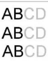 | 1. Make sure that the toner cartridge is fully installed.2. The toner level might be low. Replace the toner cartridge.3. The paper might not meet the printer's specifications (for example, the paper is too moist or too rough) (See page 22 and page 26). |
| Vertical white lines |  | Call the service personnel for help to clean the drum unit. |
| Vertical black lines | 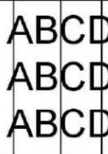 | Please clean the drum charger. Refer to Cleaning the drum charger. |
Image Problem Troubleshooting
| Problem | Image Example | Solution |
| Dirty background(partial page) |  | Check if toner is not leaked from the toner cartridge. If so, replace the toner cartridge. |
| Dirty background(entire page) | 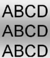 | The paper might not meet the printer's specifications (for example, the paper is too thin) (Seepaper specification). |
| Print blank page |  | Check if there is enough toner in the toner cartridge. If not, please replace the toner cartridge.If this error happens again, call service for help. |
| Defective image of regular interval |  | Clean the paper path. Refer toCleaning the Paper Path. |
| Loose toner | 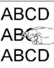 | 1. If you have observed a rougher texture on one side of your paper, try printing on the smoother side.2. The paper might not meet the printer's specifications (for example, the paper surface is not smooth or paper too thick) (See paper specification).3. Media type incorrect. Please choose proper media type for your paper. |
TECHNICAL SUPPORT
If your problem still exists after trying the above solution, please contact our technical support.
Headquarter
Avision Inc.
No. 20, Creation Road I, Science-Based Industrial Park,
Hsinchu 300, Taiwan, ROC
TEL: +886 (3) 578-2388
FAX: +886 (3) 577-7017
E-MAIL: service@avision.com.tw
Web Site: http://www.avision.com.tw
US and Canada Area
Avision Labs, Inc.
6815 Mowry Ave., Newark CA 94560, USA
TEL: +1 (510) 739-2369
FAX: +1 (510) 739-6060
E-MAIL: support@avision-labs.com
Web Site: http://www.avision.com
China Area
Shanghai Technical Support Center
7A, No.1010, Kaixuan Road, Shanghai 200052 P.R.C.
TEL :+86-21-62816680
FAX :+86-21-62818856
E-MAIL: sales@avision.net.cn
Web Site: http://www.avision.com.cn
Europe Area
Avision Europe GmbH
Bischofstr. 101 D-47809 Krefeld Germany
TEL: +49-2151-56981-40
FAX: +49-2151-56981-42
E-MAIL: info@avision-europe.com
Web Site: http://www.avision.de
6. Maintaining the Machine
The following table shows the components and their suggested cleaning cycle.
| NAME OF COMPONENT | STANDARD CLEANING CYCLE |
| Drum Charger | 10,000 pages (A4 5% coverage) |
| Paper Tray Roller | 5,000 pages |
| Manual Tray Roller | 5,000 pages |
| Paper Path | 20,000 pages |
Cleaning the Drum Charger
After copying about 10,000 pages, it is recommended to clean the developing unit. Follow these steps to clean the charger.
- Open the Side Door by pulling the handle as shown.
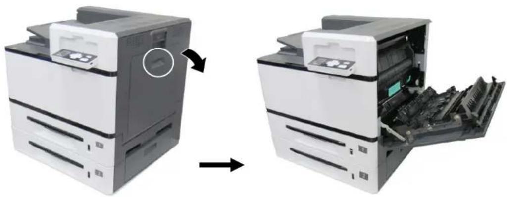
natural_image
Two views of a printer showing internal components before and after processing (no text or symbols visible)- Remove the Drum Unit.

natural_image
Close-up of a printer's internal structure showing a green clip being inserted, with a yellow dotted line highlighting the mechanism (no text or symbols visible)- Pull out the charger to the end and then back to its original position.
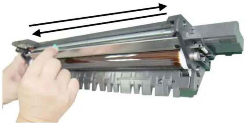
natural_image
Hand holding a cylindrical electronic device with arrows indicating motion or force direction (no text or symbols visible)- Repeat step 3 for at least three times. Make sure the charger is back to its original position. Otherwise, there is trouble to install the Drum Unit back to the machine.
Cleaning the Paper Tray Rollers
If the paper tray rollers are dirty, one paper powder is attached to it, or after 5,000 prints or copies, paper may not be fed properly or paper jam. In this case, clean the paper tray rollers.
The Cleaning Steps:
- Move the paper tray to reveal the rollers.
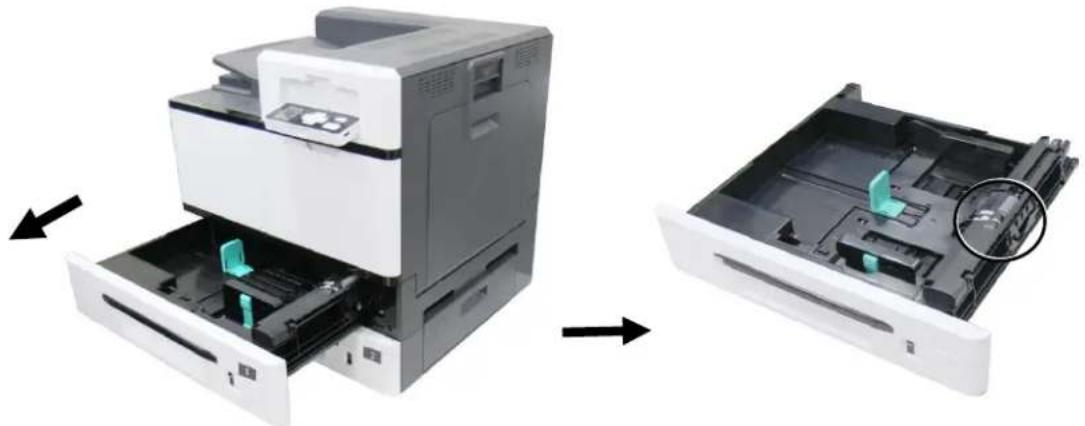
natural_image
Two views of a printer's internal structure: one showing internal components being inserted, the other showing a closed holder with a highlighted green component (no text or symbols visible)- Slightly wet a soft and lintless cloth with isopropyl alcohol (95%).
- Wipe the surface of the pickup roller, feeding roller, and the reverse roller until it is thoroughly cleaned.
Wipe the surface of the pickuproller from left to right and then from right to left.
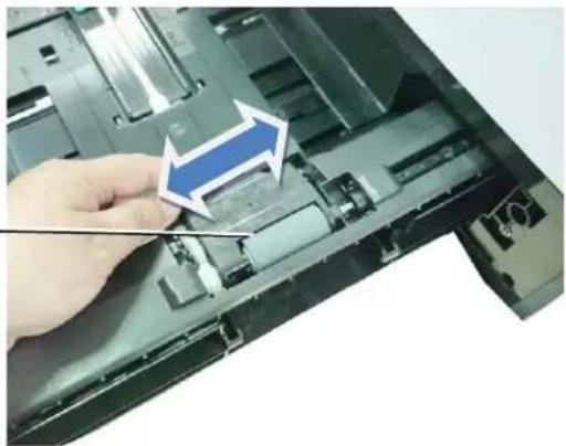
natural_image
Close-up of a hand pressing down on a computer motherboard with a blue arrow indicating the process (no text or symbols visible)- Open the Roller cover as illustrated and wipe the surface of the Feeding Roller from left to right and then from right to left.
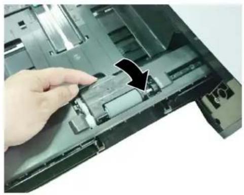
natural_image
Close-up of a hand pressing down on an open laptop case with a black arrow indicating the process (no text or symbols visible)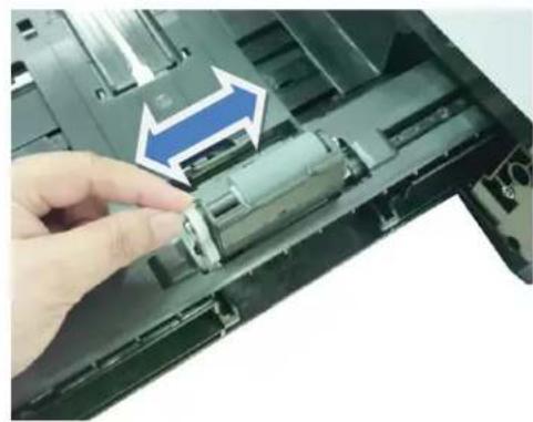
natural_image
Close-up of a hand inserting a cylindrical device into an open laptop case, with no visible text or symbols.- As shown in below, The Reverse Roller is located at the other side of the Feeding Roller. Hold two ends of the Reverse Roller Cover and remove the cover.
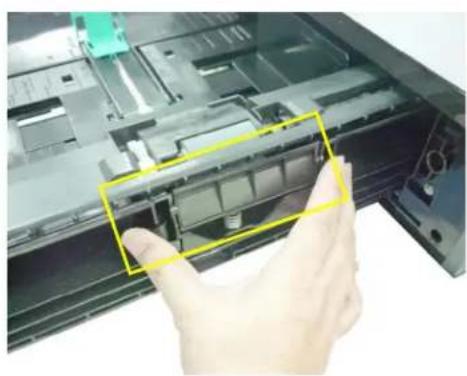
natural_image
Close-up of a hand inserting a plastic component into an open electronic device (no visible text or symbols)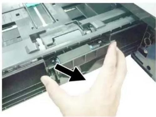
natural_image
Close-up of a hand holding a mechanical component, with a black arrow pointing to a component (no visible text or symbols)- Wipe and rotate the surface of the roller to make sure it is thoroughly cleaned.
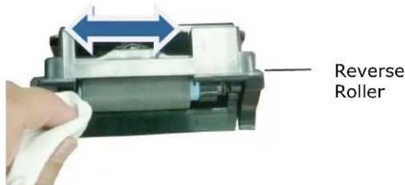
- Hold two ends of the Reverse Roller Cover to install the Reverse Roller Cover back to the machine.

Important!
Make sure to clean the rollers with a soft and lintless cloth in case the fibers may remain on the surface of the rollers.
Cleaning the Manual Tray Roller
If the paper tray rollers are is dirty, paper powder is attached to it, or after 5,000 prints or copies, paper may not be fed properly or paper jam. In this case, clean the paper tray rollers.
-
Slightly wet a soft and lintless cloth with isopropyl alcohol (95%).
-
Pull down the manual tray as shown.
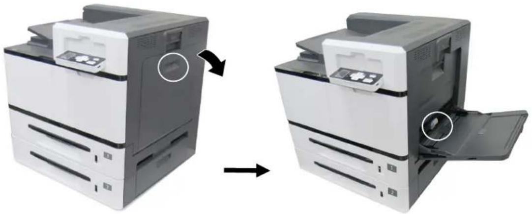
natural_image
Two views of a printer showing internal components before and after assembly (no text or symbols visible)- Push the roller internally and remove the roller.
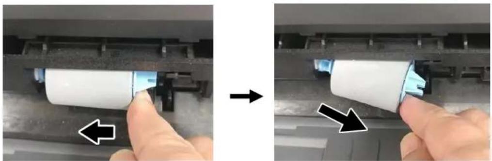
natural_image
Two-step diagram showing a hand pressing a white cylindrical component into a mechanical assembly, with arrows indicating direction (no text or symbols)- Wipe the surface of the roller from left to right and then right to left until the roller is completely cleaned.
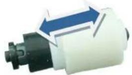
natural_image
Mechanical component with blue directional arrows indicating motion or flow (no text or symbols)Installation Step
Install the left end of the roller to the left hole and then the right end to the right hole. Note the notch on the right end has to be aligned with the tab as indicated in below.
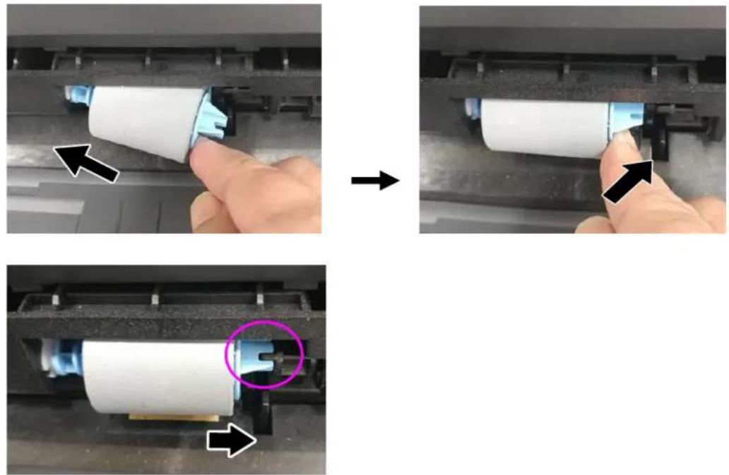
Cleaning the Toner Cartridge
If there is toner leaking on the machine, slightly wet a soft and lintless cloth with isopropyl alcohol (95%) and wipe the toner off in case you may touch the toner which is harmful to human health.
Remove the Toner Cartridge
- Open the front cover by pulling the handle as shown.
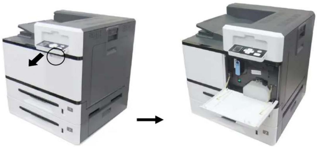
natural_image
Two views of a printer showing internal components before and after assembly (no text or symbols visible)- Use your right hand to unlock the toner cartridge by pressing down the 'lock switch' and at the same time use your left hand to hold the handle of the toner cartridge and pull it out of the printer.
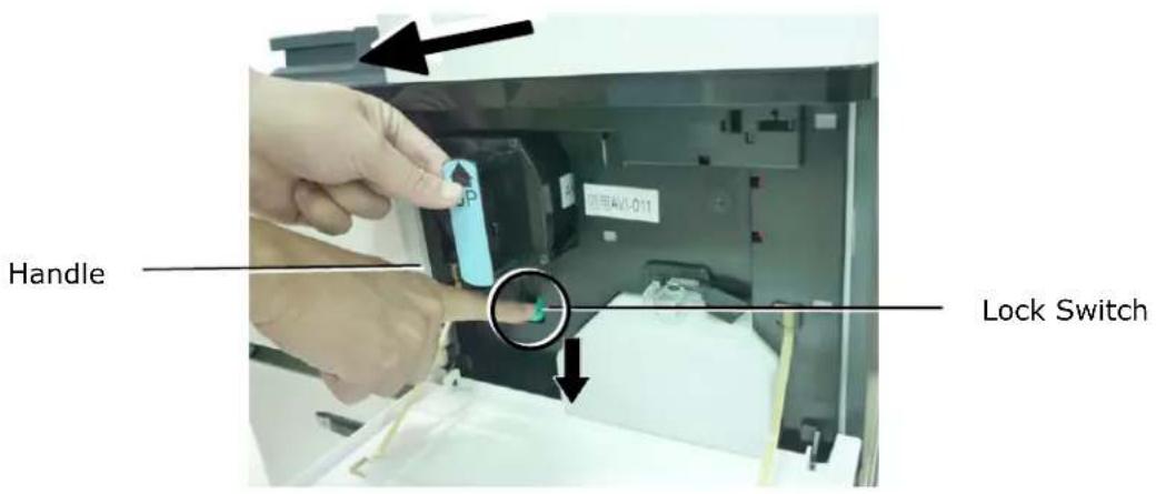
- Slightly wet a soft and lintless cloth with isopropyl alcohol (95%) and wipe the toner off the cartridge.
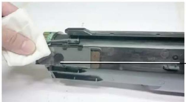
natural_image
Close-up of a hand holding a white cloth next to a mechanical component, no visible text or symbolsToner Leakage
Install the Toner Cartridge
- Hold the handle of the toner cartridge and insert it to its proper position as shown.
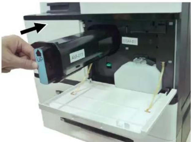
-
Push the Toner Cartridge to the end. A "click" sound means the installation was successful.
-
Close the Front Cover.

Important!
- Be careful not to spill toner from the waste toner can. Do not inhale toner or allow toner to get into your eyes.
- If toner gets on your clothing or other fabric, wipe off the toner with a dry cloth. Wash the items in cold water and air dry. Hot water causes the toner to penetrate the fibers of the clothes.
Cleaning the Paper Path
During the printing process, paper powder, toner, and dust particles can accumulate inside the product. Over time, this buildup can cause print quality issues such as toner specks, smears, or dust particles on the edge of paper. If you are experiencing these problems, clean the paper path. To keep optimal printing quality, the paper path needs to be cleaned after approximately every 20,000 prints. However, the guideline might vary based on the type of paper you are printing (for example, visible paper powder on paper or paper has not been cut evenly).
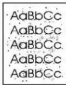
Toner specks or dots on the printouts
To clean the paper path, follow these steps:
- Turn off the product, disconnect the power cord, and then wait for the product to cool.
- Open the side door.
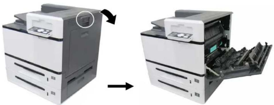
natural_image
Two views of a printer showing the left and right sides of an open image (no text or symbols visible)- Pull down the lock latches on the top of the fuser to open the Fuser Cover.
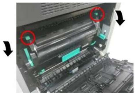
natural_image
Interior view of a printer or scanner with visible mechanical components and two red-circled arrows indicating specific parts (no text or symbols present)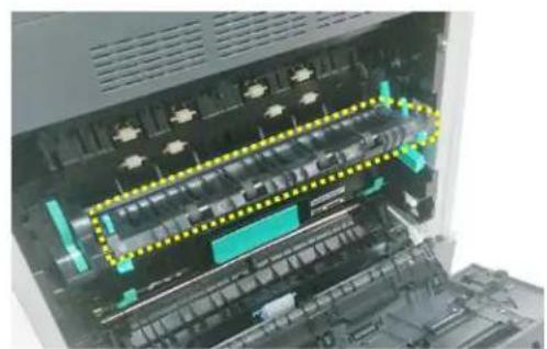
natural_image
Interior view of a computer motherboard showing drive bays and circuitry (no visible text or labels)- Gently wipe the surface of the rollers and paper path as illustrated with a soft, dry cloth that is lightly dampened with isopropyl alcohol.
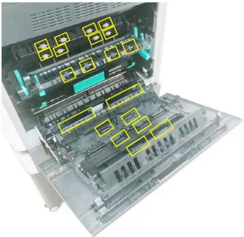
natural_image
Interior view of a computer chassis showing internal components and storage areas (no visible text or symbols)7. Replacing the Consumables
The following table shows the parts and their suggested replacement cycle. The replacement cycles above are rough guidelines for the case using A4/Letter sized woodfree or wood containing paper of 80 g/m ^2 (20 lbs) in weight. These cycles vary according to the type of paper used and how frequently the product is used and cleaned. Please replenish the consumables from the store where you purchased the product or a Avision authorized service provider.
| NAME OF COMPONENT | RECOMMENDED REPLACEMENT CYCLE |
Waste Toner Can | When waste toner is full |
Toner Cartridge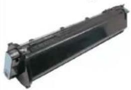 | 20K sheets (5% Coverage) |
Paper Tray Roller | 200K sheets |
Manual Tray Roller | 50K sheets |
Drum Unit | 150K sheets |
Developing Unit | 150K sheets |
Fuser

natural_image
Black cylindrical electronic component with visible internal structure and mounting holes (no text or symbols)300K sheets
Replacing the Waste Toner Can
Follow these steps to replace the waste toner can:

Important!
• DO NOT reuse the waste toner can.
• DO NOT put the waste toner can into a fire. It could explode.
- Be careful not to spill the toner. DO NOT inhale or allow it to get into your eyes.
Removing the Waste Toner Can
- Open the front door by pulling the handle as shown.
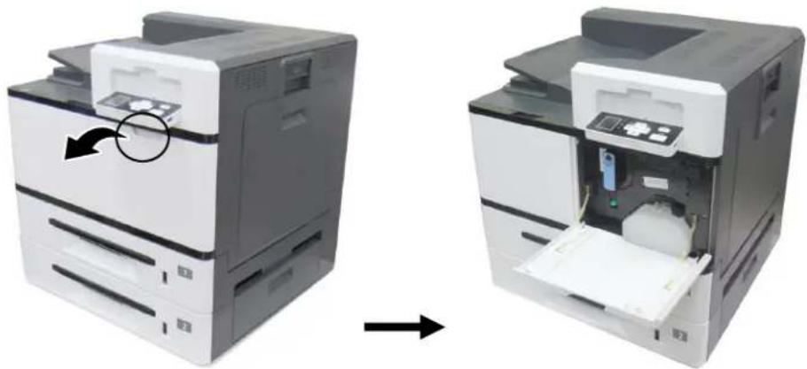
natural_image
Two views of a printer showing internal components before and after assembly (no text or symbols visible)- Squeeze the top of the waste toner can and remvoe it from the machine as shown.
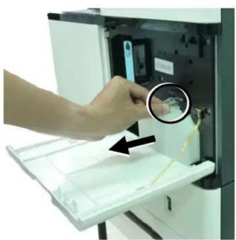
natural_image
Hand inserting a small object into an open printer case, with a magnified inset showing the device's internal structure (no text or symbols visible)- Insert the cap of the waste toner can and seal it with tape to let the cap firmly secured.
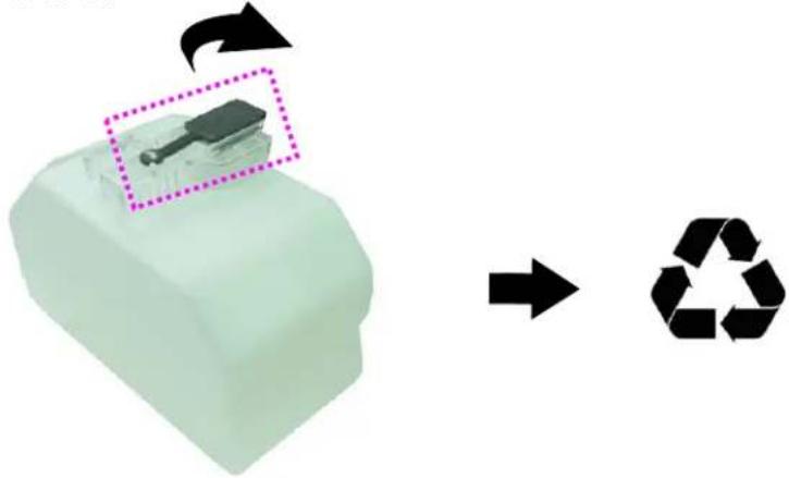
natural_image
3D illustration of a plastic component with an arrow indicating recycling (no text or symbols present)- Place the waste toner can into its original plastic bag to ensure the toner will not spill.

Important!
- Be careful not to spill the toner. DO NOT inhale or allow it to get into your eyes.
- As the waste toner may be hazardous to both environment and human health, please place the waste toner can into a plastic bag and the original toner cartridge box, and then deliver to our authorized distributors or service personnel.

flowchart
graph LR
    A["Recyclable Plastic Container"] --> B["Recyclable Box with Receiving Image"]
    B --> C["Recyclable Symbol"]
Reinstalling the Waste Toner Can
- Open the cap.
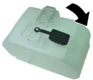
natural_image
White plastic electronic device with a black handle and arrow indicator (no text or symbols)- Hold the handle of the waste toner can and insert it to its original place. A "click" sound means the installation was successful.
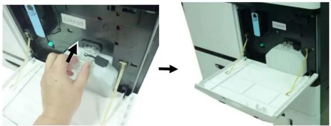
natural_image
Two-panel image showing a hand inserting a small component into an open device, with no visible text or symbols.- Close the Front Cover as shown.
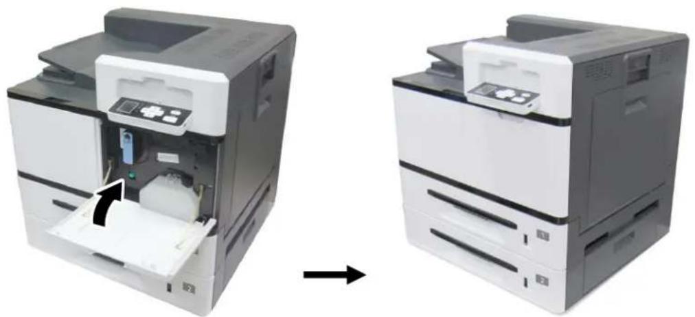
natural_image
Two views of a printer showing internal components before and after assembly (no text or symbols visible)Replacing Toner Cartridge
Follow these steps to replace the toner cartridge:

Important!
To maintain the EP Charger in good condition, please clean the EP charger each time after replacing the toner cartridge. Refer to the following section, Cleaning the EP Charger – on how to clean the charger.
Removing the Toner Cartridge
- Open the front cover by pulling the handle as shown.
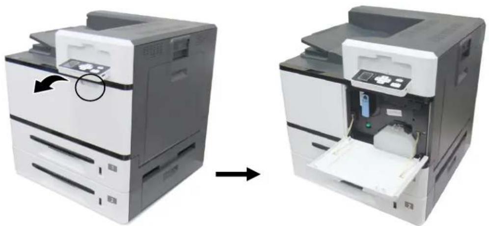
natural_image
Two views of a printer showing internal components before and after processing (no text or symbols visible)- Use your right hand to unlock the toner cartridge by pressing down the 'lock switch' and at the same time use your left hand to hold the handle of the toner cartridge and pull it out of the printer.
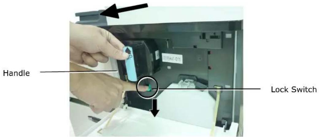
Installing the Toner Cartridge
- Remove the package cushion and tapes on the toner cartridge. Tilt the toner cartridge up and down and then right and left 10 times to distribute the toner evenly inside the cartridge.

natural_image
Two views of a cylindrical electronic component with internal components, shown in two different orientations (no text or symbols visible)- Hold the handle of the toner cartridge and insert it to its proper position as shown.
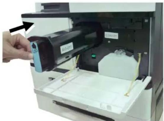
natural_image
Close-up of a printer's internal structure showing a hand inserting a device into a paper holder (no visible text or symbols)- Close the front cover.

Important!
- Be careful not to spill the toner. DO NOT inhale or allow it to get into your eyes.
- If toner gets on your clothing or other fabric, wipe off the toner with a dry cloth. Wash the items in cold water and air dry. Hot water causes the toner to penetrate the fibers of the clothes.
- Do not dispose of the toner cartridge. Put the used toner cartridge into the bundled plastic bag, and then return it to a dealer or service representative. The latter recycles or deals with the collected toner cartridges in accordance with the relevant regulations.

flowchart
graph LR
    A["Printer"] --> B["Recycle Symbol"]
    B --> C["Recycle Symbol"]
Replacing the Paper Tray Rollers
After approximately 200,000 prints or copies, the roller may be worn out and you may have difficult in feeding paper properly. In this case, please replace the roller with a new one and follow the steps in below to complete the replacement.
The removing steps
- Lift the front side of the paper tray, and then pull the paper tray out of the product. Locate the feeding roller as indicated.

natural_image
Two views of a printer's internal structure: one showing a paper feeding into a printer, the other showing a closed printer with a green insert and highlighted part (no text or symbols visible)- Press the front end of the Roller Cover inward to open the cover. Lift the Feeding Roller upward to remove it.
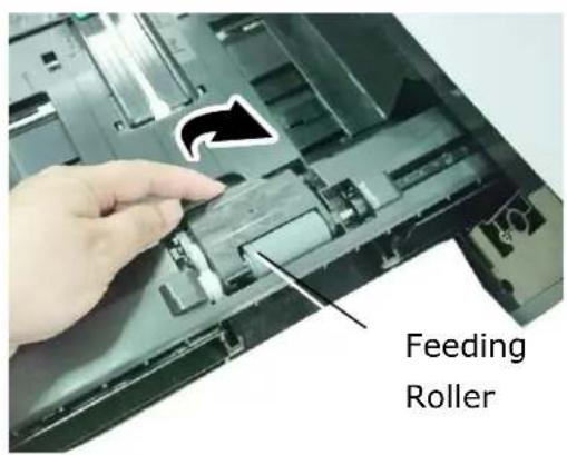
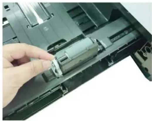
natural_image
Close-up of a hand inserting a plastic cylindrical component into a black electronic device casing (no text or symbols visible)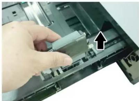
natural_image
Close-up of a hand inserting a component into a laptop case, with an arrow pointing to the component (no visible text or symbols)- Press two ends of the Reverse Roller inward to remove the Reverse Roller.
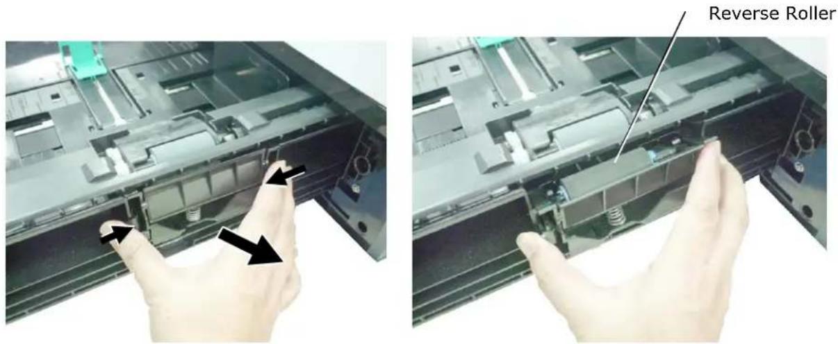
The reinstallation steps
- Insert the Feeding Roller vertically to its original slot.
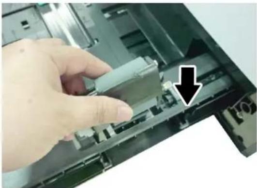
natural_image
Close-up of a hand inserting a small electronic component into a laptop case, with a black arrow pointing to the component (no text or symbols visible)- Close the Roller Cover as shown.
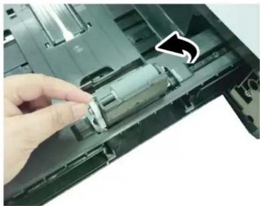
natural_image
Close-up of a hand inserting a component into a computer case, with an arrow indicating the direction (no text or symbols visible)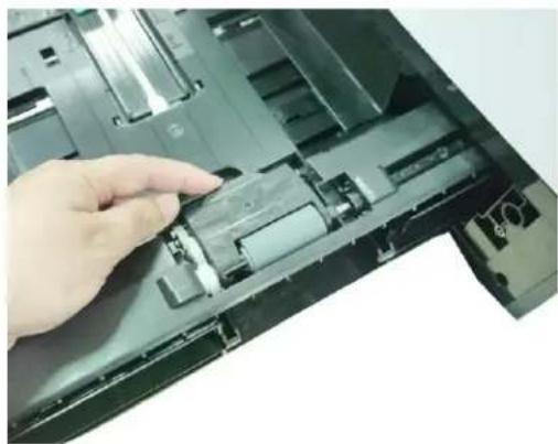
natural_image
Close-up of a hand inserting a plastic component into a black electronic device casing (no visible text or symbols)- Hold two ends of the Reverse Roller Assembly and insert it to its original slot as shown.

natural_image
Close-up of a hand holding an open computer motherboard with arrows pointing to specific components (no visible text or symbols)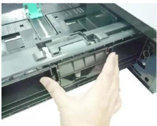
natural_image
Hand opening a device into a black plastic enclosure (no visible text or symbols)Replacing the manual tray rollers and pad
After approximately 200,000 prints or copies, the roller may be worn out and you may have difficult in feeding paper properly. In this case, please replace the roller with a new one and follow the steps in below to complete the replacement.
The removing procedure
1. Pull down the manual tray.
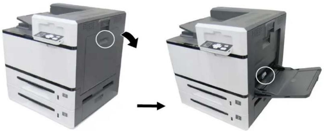
natural_image
Two views of a printer showing the left and right sides of a paper airplane, with no visible text or symbols.2. Press down the tab at the end of the roller as shown.
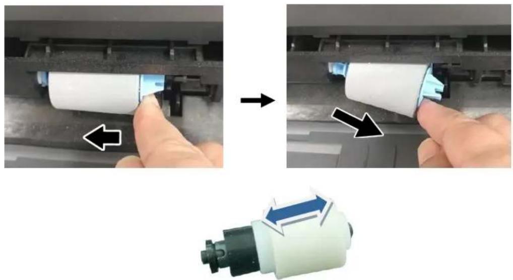
natural_image
Three-step process showing a hand pressing a white cylindrical component on a mechanical assembly, with arrows indicating direction of movement (no text or symbols present)The reinstallation procedure
Install the left end of the roller to the left hole and then the right end to the right hole. Note the notch on the right end has to be aligned with the tab as indicated in below.
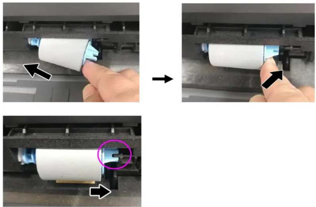
Replacing the Drum Unit
The Removing Procedure
- Turn off the power and disconnect the power cable. Wait for 10 minutes to cool down the machine.
- Pull down the Side Door.
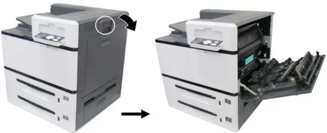
natural_image
Two views of a printer showing internal structure and external assembly (no text or symbols visible)- Hold the handle of the Drum Unit and remvoe it from the machine as shown.

Reassembling Steps:
- Remove the plastic bag, tape, and then press down the Release Arms to pull out the protective film.
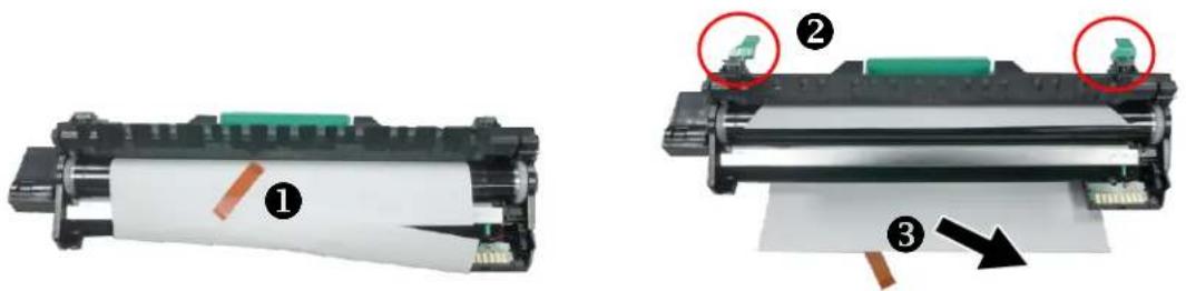
natural_image
Two views of a printer with visible internal components and labeled parts (no text or symbols present)- Pull up the Release Arms on both ends.

natural_image
Two-step assembly diagram showing a black rectangular component with teal internal structure before and after, with arrows indicating transformation (no text or symbols present)
Important!
- To avoid damage the drum unit, please install it after removing the protection cushions. Do not expose the drum unit to light.
-
Deliver the old drum unit to an approved recycling center.
-
Holding the handle of the Drum Unit, insert the Drum Unit horizontally into the slot along the top of the support frame on both sides, as shown in the figure.
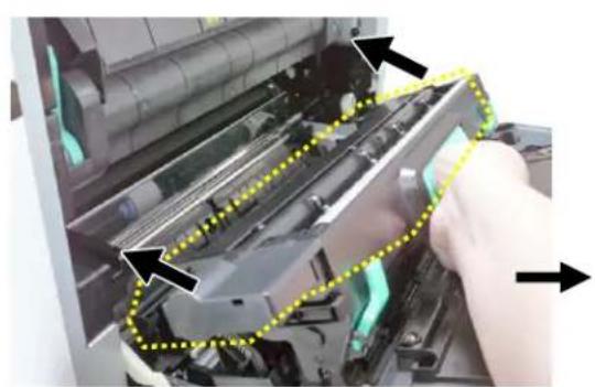
natural_image
Close-up of a printer's internal structure with arrows indicating assembly or inspection, no visible text or symbols
natural_image
Interior view of a printer or printer showing internal rollers and circuitry (no visible text or symbols)- Close the Side Door and then the the Manual Tray Cover as shown.
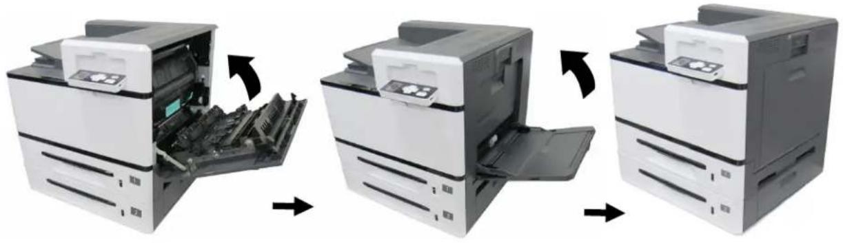
natural_image
Three-step illustration of a printer's internal structure showing open, closed, and closed states (no text or symbols)Replacing the Developing Unit
Follow these steps to replace the Developing Unit:
The Removing Steps:
- Turn off the machine until it has been cooled down.
- Open the Side Door by pulling down the handle as shown.
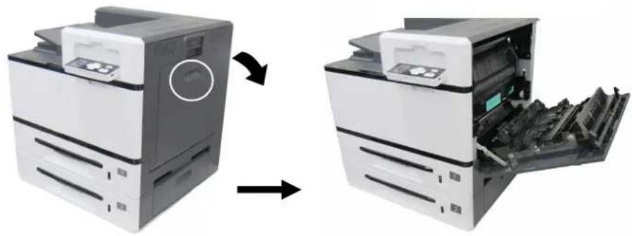
natural_image
Two views of a printer showing the left and right assembly of the internal structure (no text or symbols visible)- Hold the handle of the Drun unit and pull it out.
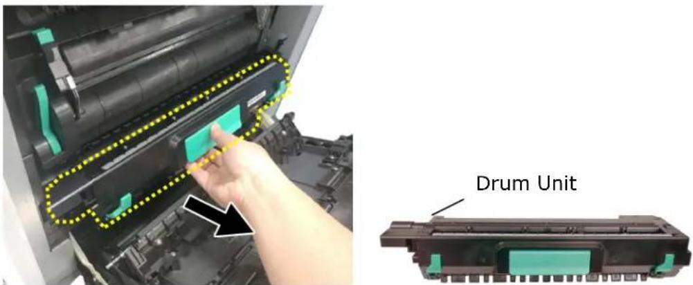
- Open the paper guide latch in a clockwise direction ①, and then push up ② to fix the paper guide.
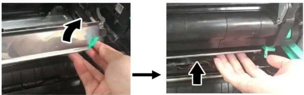
natural_image
Close-up of hands installing or adjusting a mechanical component, showing a blue tool and green tool (no text or symbols visible)- Hold the handles of the developing unit and gently remove it from the machine as shown.
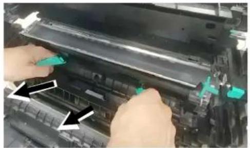
natural_image
Close-up of hands installing or adjusting a mechanical component with green tool tips (no visible text or symbols)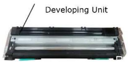

Notice to return the used developing unit!
Insert the protective film from the original package into the roller of the developing unit, and stick the tape ①, insert the pin into the reserved hole ②, insert the sponge ④ to the toner exit hole, finally stick the tape ③ on the sponge to avoid vibration during transportation, and then put the developing unit into its original plastic bag, foam, and packing box to return to the manufacturer.

flowchart
graph LR
    A["① Battery Disposal"] --> B["② Reuse to Battery"]
    B --> C["③/④ Recycling"]
    C --> D["④ Recycling"]
Reassembling Steps:
- Remove the plastic bag and protective package including protective film①, plugs ②, tapes ③, and the sponge ④ in the toner exit hole.
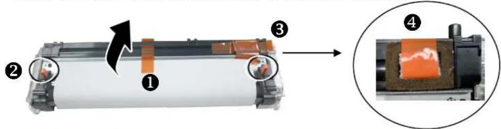

Important!
Do not remove the transparent plastic protective cover on the surface of the developing unit as shown in the figure to avoid abnormal images.
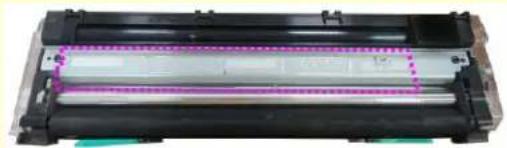
natural_image
Close-up of a black cylindrical electronic component with a dotted purple line indicating a measurement or alignment (no visible text or symbols)- Open the handle of the developing unit and hold the handle with both hands, as shown in the figure below.
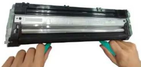
natural_image
Close-up of hands holding a black cylindrical electronic device with green buttons, no visible text or symbols- Hold the handle with both hands, placing the front end of the developing unit to the top of the rails on both sides ①, and then gently push the developing unit into the machine along the rails ②. Make sure the handles are closed and left flat on the surface of the developing unit as shown in below ③.
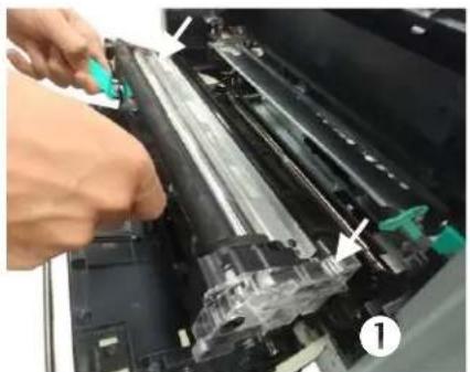
natural_image
Close-up of a printer's internal components being inserted, showing mechanical parts and a green tool (no text or symbols visible)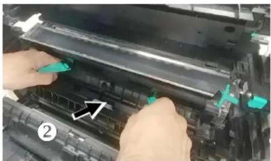
natural_image
Close-up of hands installing or adjusting a black plastic component on a machine, with no visible text or symbols.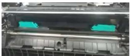
natural_image
Close-up of a printer's internal structure showing green plastic bands (no text or symbols visible)3
- Pull down the latch of the paper guide counterclockwise to restore the latch of the paper guide to its original status.
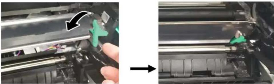
natural_image
Close-up of a hand holding a tool next to a mechanical component, showing a green plus symbol and arrow (no text or symbols present)- Hold the handle of the Drum Unit and slide it into the machine as shown.
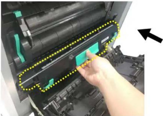
natural_image
Close-up of a hand pressing a green button on a printer's tray, with yellow dotted lines highlighting the mechanism (no text or symbols visible)- Close the Side Door and then the Manual Tray Cover as shown.
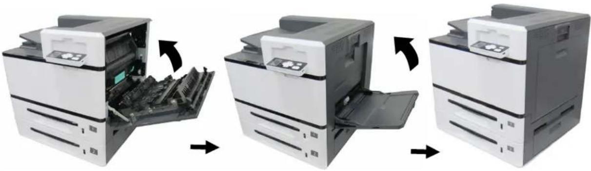
natural_image
Three-step illustration of a printer's internal processing, showing open and closed states with arrows indicating transformation (no text or symbols present)Replacing the Fuser
The Removing Steps

Important:
After the product has been used for a while, please do not touch the inside of the product since the temperature is very high. To replace the fuser, please first turn the machine off and wait until it has been cooled down.
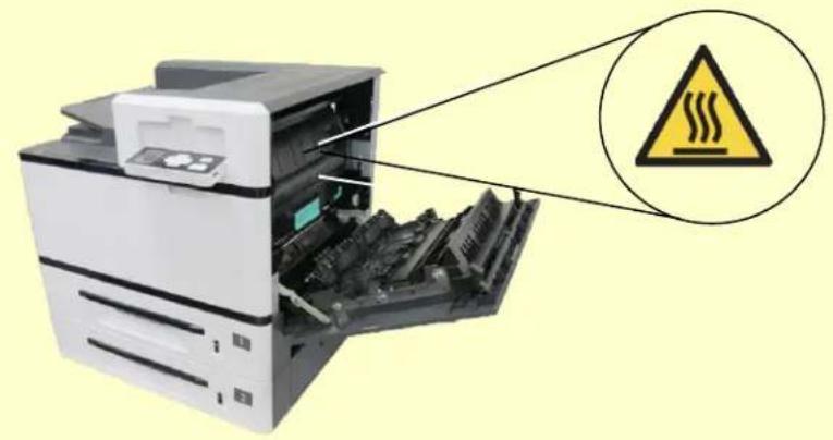
natural_image
Diagram of a printer with internal components and a warning symbol (no text or labels present)- Turn off the printer and wait until it has cooled down.
- Open the Side Door by pulling down the handle as shown.
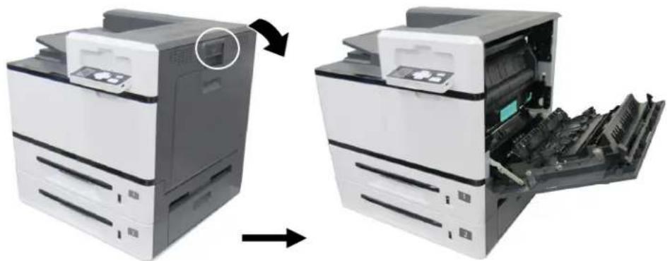
natural_image
Two views of a printer showing internal structure and external assembly (no text or symbols visible)- Pull down the handles on both sides of the fuser.
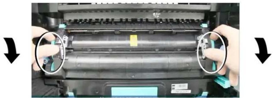
natural_image
Close-up of hands operating a printer with visible mechanical components and two arrows indicating rotation (no text or symbols)- Pull down the tabs to open the cover.
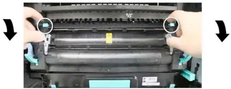
natural_image
Close-up of hands installing a printer's internal structure with a green component, showing no text or symbols on the device itself.- Press the latch of the cover and remove the cover as shown in below.
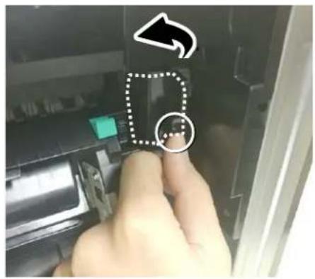
- Remove the red cable and then the black cable.
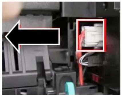
natural_image
Close-up of a mechanical device with a highlighted component (no visible text or symbols)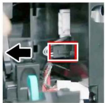
natural_image
Close-up of a mechanical device with a highlighted component (no visible text or symbols)- Pull the fuser cover back and then press the blue latch on both sides inwardly as illustrated.
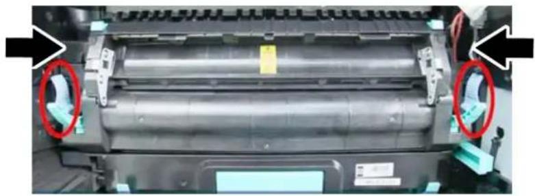
natural_image
Close-up of a printer's internal structure with red-circled components, no visible text or symbols- Hold the handles on both sides of the fuser and remove the fuser from the machine.
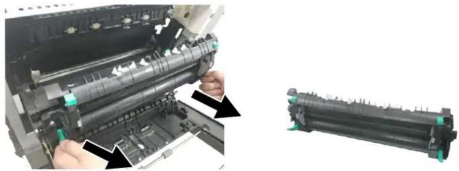
natural_image
Close-up of a printer's internal mechanism showing the main page and side view of a cylindrical roller (no text or symbols visible)
Important!
Do not dispose of the toner cartridge. Stick the cables with tape, put it in the original plastic bag and box, and then return to the authorized dealer or service personnel. The latter will follow Recycling or disposing of the collected fusers according to relevant regulations.

flowchart
graph LR
    A["Raw Material"] --> B["Recycle Unit"]
    B --> C["Recycle"]
Reinstallation Steps
- Remove the protective tape of the new fuser.
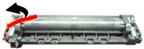
natural_image
Mechanical component with a cylindrical body and red arrow indicating direction (no visible text or symbols)- Turn over the fuser to find the serial number (AXXXXXXXX). Write it down as it is required to reset the fuser count.
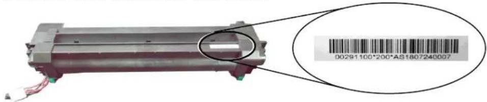
- Pull down the handles of the fuser and then hold the handles with two hands to install it back to the original place in the machine.
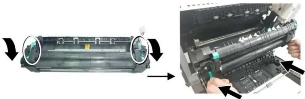
natural_image
Two-step photo showing a printer's internal structure before and after assembly, with arrows indicating process direction (no text or symbols present)- Press the latches on both sides outward as illustrated.
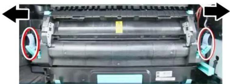
natural_image
Close-up of a mechanical component with two circular annotations highlighting features, no visible text or symbols.- Pull down the fuser cover.
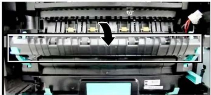
natural_image
Close-up of a printer's internal structure showing internal components and a black arrow indicating a process (no visible text or symbols)- Connect the black cable and then the red cable. Close the cable cover.
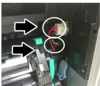
natural_image
Close-up of a mechanical device with highlighted components and arrows indicating direction (no readable text or symbols)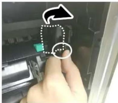
- Close the fuser cover back to its original position.
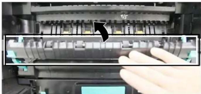
natural_image
Close-up of a printer's internal structure with a hand operating it, showing no visible text or symbols.- Pull up the handles on both sides.
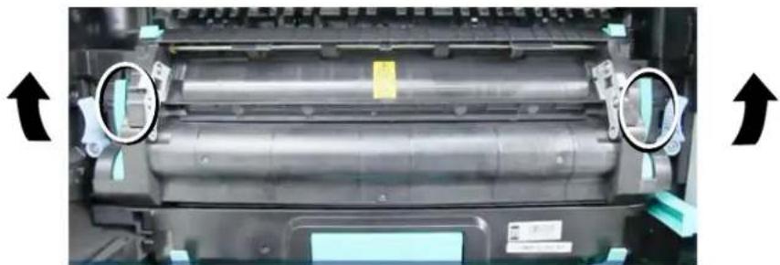
natural_image
Close-up of a printer's internal structure with two circular arrows pointing to the top view (no text or symbols visible)- Close the Side Door and then the Manual Tray Cover as shown.
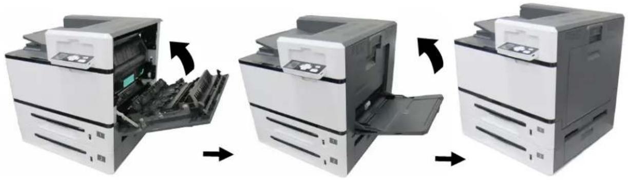
natural_image
Three-step illustration of a printer's internal structure showing open, closed, and open states (no text or symbols)-
Press the Power button to turn on the machine.
-
Reset the fuser count on the product's web page as described in below:
1). Connect the product to a network via an ethernet cable.
2). Open your browser and type the product's IP address on the URL address. Press OK and the product's web page will be displayed.
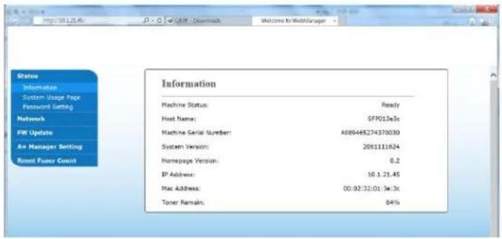
3). Choose [Properties] and then click [Reset Fuser Count]. Enter fuser's serial number and then press [Apply], finally enter the administrator's password to reset the fuser count.
8. Specifications
All specifications are subject to change without notice.
| General | ||
| Processor | 800MHz Dual Core Cortex A9(build in SOC) | |
| Memory | 512M DDR2 SDRAM | |
| Max media size | A3 size | |
| Resolution | 600x 600dpi | |
| Printing speed | 40 ppm | |
| Warmup time | < 26 second | |
| Recommended Monthly Print Volumn | 20,000 pages | |
| Maximum monthly print duty cycle | 200,000 pages | |
| Manual tray | Paper capacity | 100 pages (70g/m2 plain paper) |
| Paper size | A3, Double Letter, 8K, 16K, A6, A4, B6(JIS), B4(JIS), A5, B5(JIS), Letter, Legal 13, Legal, Japanese PostCard, Customized size: 100x145 ~ 304.8x431.8 mm (3.93" x 5.7" ~ 12" x 17") | |
| Paper weight | 60~158 g/m2 (16~42 lbs) | |
| Tray 1~4 | Paper capacity | 500 pages (70g/m2 plain paper) |
| Paper size | A3, A4, B4(JIS), A5, B5(JIS), Letter, Legal 14, Double Letter | |
| Paper weight | 60~105 g/m2 (16~28 lbs) | |
| Support paper tray | Standard 500 pages input tray | |
| Paper output | Top output | |
| Paper output capacity | 530 pages | |
| Duplex printing unit | Build-in | |
8 Specifications
| Duplex print | Paper size | A3, A4, B4(JIS), A5, BS(JIS), letter, legal customized size: 148x210~304.8x431.8 mm (5.8" x 8.3" ~ 12" x 17") |
| Paper weight | 60~105 g/m2 (16~28 lbs) | |
| Network print | Build-in | |
| Connectivity | USB 3.2 Gen 1x1/RJ-45 Etherent 10/100/1000 Mb | |
| Printer language | GDI/PCL/PS | |
| Supported operation system | Windows 7, Windows 8, Windows 10 | |
| Dimemson (WxDxH) | 575x563x597mm (22.6" x 21.1" x 23.6") | |
| Weight | 35kg | |
| Power source | 100/120V, 200/240V (50Hz /60Hz ) | |
| Power consumption | <720W | |
| Operation Environment | Temperature | 5°C~35°C |
| Humidity | 15%~85% (no dew) | |
| Printer life | 5 years or 1,000,000 pages | |
| Toner | 20,000 pages (A4 5% cover rate) | |
| Drum unit | 150,000 pages | |
| Developing unit | 150,000 pages | |
| Fuser | 300,000 pages | |
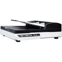
- AP400 Printer User's Guide
- Safety During Operation
- WARNING:
- CAUTION:
- Important:
- Note:
- Notice
- Important
- Copyrights and Trademarks
- Warranty
- Federal Communications Commission (FCC) compliance information statement
- Part 15
- CE
- European Union Regulatory Notice
- CE Warning
- Safety Information
- Installation and the Operating Environment
- Safety Information During Operation
- Caution
- About the Consumables
- Safety Information when using power cord and the USB cable
- Warning
- SAFETY INSTRUCTION
- Table of Contents
- Getting Started .... 1
- Installation 8
- Printing 36
- Configuring the Machine 57
- Troubleshooting......67
- Maintaining the Machine 98
- Replacing the Consumables 108
- Features
- External View
- Buttons
- Description
- Installation
- Precautions
- Removing the Box and Packing Material
- Unpacking Steps
- Removing the Shipping Tapes on the Machine
- Removing the Locking Latch on the Machine
- Installing the Toner Cartridge
- Important!
- WARNING!
- Installing the Developing Unit
- Caution!
- Installing the Drum Unit
- Lifting Up the Output Bin
- Loading Paper Into The Main Input Tray
- Loading Paper Into the Manual Tray
- Turning On The Printer
- Connecting to the Network
- Installing the Printer Driver
- System Requirement
- For USB Interface Users
- Uninstalling the Printer Driver
- For Network Interface Users
- Host Name
- IP Address
- Automatic Search
- Changing the Product's IP Address in a Wired Network
- Printing
- Normal Printing
- 2-Sided Printing
- Combining Multiple Pages into One Sheet of Paper
- Enhancing Your Print Quality
- More Printing Features
- The Basic Tab
- Orientation
- Copies
- Effect
- The Paper Tab
- The Layout Tab
- N-up
- N-up Style:
- The Watermark Tab
- Adding a new waterk text
- Editing a current watermark text
- Removing a current watermark text
- Adding a new waterk image
- Editing a current watermark image
- Removing a current watermark Image
- The Duplex Tab
- Booklet
- Booklet (No Reduction)
- Booklet Layout:
- Portrait Orientation
- Landscape Orientation
- The Job Build Tab
- The More Tab
- Configuring the Machine
- Customizing System's Settings via the Control Panel
- Menu Items on the LCD Screen
- Network
- Report
- Information
- Customize System's Settings via the Embedded Web Page
- Setting Items on the Webpage
- Status
- System Settings
- FW Update
- A + Manager Setting
- Reset Fuser Count
- Troubleshooting
- Monitoring Your Printer Using Printer Status Monitor
- Accessing Printer Status Monitor
- Getting Printer Status Details
- Setting Monitoring Preferences
- Clearing A Warning or Error Message
- PaperJam Errors
- Notice when removing the jammed paper:
- Paperjam Areas
- How to remove the jammed paper in the drum unit
- How to remove the jammed paper in the fuser
- TECHNICAL SUPPORT
- Headquarter
- Avision Inc.
- US and Canada Area
- Avision Labs, Inc.
- China Area
- Shanghai Technical Support Center
- Europe Area
- Avision Europe GmbH
- Maintaining the Machine
- Cleaning the Drum Charger
- Cleaning the Paper Tray Rollers
- The Cleaning Steps:
- Cleaning the Manual Tray Roller
- Installation Step
- Cleaning the Toner Cartridge
- Remove the Toner Cartridge
- Install the Toner Cartridge
- Cleaning the Paper Path
- To clean the paper path, follow these steps:
- Replacing the Consumables
- Replacing the Waste Toner Can
- Removing the Waste Toner Can
- Reinstalling the Waste Toner Can
- Replacing Toner Cartridge
- Removing the Toner Cartridge
- Replacing the Paper Tray Rollers
- The removing steps
- The reinstallation steps
- Replacing the manual tray rollers and pad
- The removing procedure
- Pull down the manual tray.
- Press down the tab at the end of the roller as shown.
- The reinstallation procedure
- Replacing the Drum Unit
- Reassembling Steps:
- Replacing the Developing Unit
- The Removing Steps:
- Notice to return the used developing unit!
- Replacing the Fuser
- Reinstallation Steps
- Specifications
Brand : AVISION
Model : AP400
Category : Printer