
Geyser Move - Smoke machine Chauvet - Free user manual and instructions
Find the device manual for free Geyser Move Chauvet in PDF.


| Product Type | Fog Machine with Moving Head |
| Brand | Chauvet |
| Model | Geyser Move |
| Power Consumption | 300 W |
| Heat-up Time | 5 minutes |
| Fluid Tank Capacity | 0.5 L |
| Fluid Consumption | 10 mL/min |
| Output Volume | 2,500 cfm |
| Moving Head Range | 180° tilt |
| Control Options | Manual, DMX (optional) |
| Dimensions (LxWxH) | 15.5 x 11.8 x 9.8 in (39.4 x 30 x 24.9 cm) |
| Weight | 11 lbs (5 kg) |
| Power Supply | 100-240 V, 50/60 Hz |
| Safety Features | Thermal cut-off, non-slip feet |
| Maintenance | Clean nozzle regularly; use only approved fog fluid |
| Spare Parts | Heater element, pump, fuse |
| Included Accessories | Fog machine, remote control, user manual |
Frequently Asked Questions - Geyser Move Chauvet
User questions about Geyser Move Chauvet
0 question about this device. Answer the ones you know or ask your own.
Ask a new question about this device
Download the instructions for your Smoke machine in PDF format for free! Find your manual Geyser Move - Chauvet and take your electronic device back in hand. On this page are published all the documents necessary for the use of your device. Geyser Move by Chauvet.
USER MANUAL Geyser Move Chauvet
natural_image
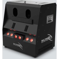
Exterior view of a GEVSER MOVE 3D printer with red laser lights (no visible text or symbols beyond branding)Edition Notes
The Geyser Move User Manual includes a description, safety precautions, installation, programming, operation, and maintenance instructions for the Geyser Move as of the release date of this edition.
Trademarks
Chauvet, Chauvet DJ, the Chauvet logo, and Geyser are registered trademarks or trademarks of Chauvet & Sons, LLC (d/b/a Chauvet and Chauvet Lighting) in the United States and other countries. Other company and product names and logos referred to herein may be trademarks of their respective companies.
Copyright Notice
The works of authorship contained in this manual, including, but not limited to, all designs, text, and images are owned by Chauvet.
© Copyright 2024 Chauvet & Sons, LLC. All rights reserved.
Electronically published by Chauvet in the United States of America.
Manual Use
Chauvet authorizes its customers to download and print this manual for professional information purposes only. Chauvet expressly prohibits the usage, copy, storage, distribution, modification, or printing of this manual or its content for any other purpose without written consent from Chauvet.
Document Printing
For best results, print this document in color, on letter size paper (8.5 x 11 in), double-sided. If using A4 paper (210 x 297 mm), configure the printer to scale the content accordingly.
Intended Audience
Any person installing, operating, and/or maintaining this product should completely read through the guide that shipped with the product, as well as this manual, before installing, operating, or maintaining this product.
Disclaimer
Chauvet believes that the information contained in this manual is accurate in all respects. However, Chauvet assumes no responsibility and specifically disclaims any and all liability to any party for any loss, damage, or disruption caused by any errors or omissions in this document, whether such errors or omissions result from negligence, accident, or any other cause. Chauvet reserves the right to revise the content of this document without any obligation to notify any person or company of such revision; however, Chauvet has no obligation to make, and does not commit to make, any such revisions.
Document Revision
Go to www.chauvetdj.com for the latest version.
Revision Date Description
1 06/2024 Initial release.
TABLE OF CONTENTS
1. Before You Begin .... 1
What Is Included 1
Unpacking Instructions.... 1
Claims 1
Text Conventions 1
Symbols 1
Safety Notes.... 2
FCC Statement of Compliance 3
RF Exposure Warning for North America and Australia.... 3
2. Introduction...... 4
Product Overview 4
Product Dimensions 4
3. Setup.... 5
AC Power 5
Fuse Replacement 5
Mounting 6
Orientation.... 6
Rigging 6
Inverting the Tank 7
4. Operation.... 9
Control Panel Operation.... 9
Menu Map 9
DMX Configuration.... 9
Personality and Starting Address 9
Zones for DMX Control 10
DMX Charts 10
Geyser WRC Configuration.... 11
Color Selection.... 11
Motor Angle Selection 11
Geyser WRC Overview 11
5. Maintenance.... 12
Product Maintenance 12
Fog Machine Maintenance.... 12
Storage.... 12
6. Technical Specifications.... 13
Contact Us.... 14
Warranty & Returns.... 14
1. Before You Begin
What Is Included
- Geyser Move
- Power cable
• Geyser WRC (Wireless Remote Control) and receiver - Hanging bracket (x2)
- Quick Reference Guide
Unpacking Instructions
Carefully unpack the product immediately and check the container to make sure all the parts are in the package and are in good condition.
Claims
If the box or the contents (the product and included accessories) appear damaged from shipping, or show signs of mishandling, notify the carrier immediately, not Chauvet. Failure to report damage to the carrier immediately may invalidate a claim. In addition, keep the box and contents for inspection.
For other issues, such as missing components or parts, damage not related to shipping, or concealed damage, file a claim with Chauvet within 7 days of delivery.
Text Conventions
| Convention Meaning |
| 1–512 A range of values |
| 50/60 A set of values of which only one can be chosen |
| Settings A menu option not to be modified |
| A key to be pressed on the product's control panel |
| ON A value to be entered or selected |
Symbols
| Symbol Meaning | |
 | Electrical warning. Not following these instructions may cause electrical damage to the product, accessories, or the user. |
 | Critical installation, configuration, or operation information. Not following these instructions may make the product not work, cause damage to the product, or cause harm to the operator. |
 | Important installation or configuration information. The product may not function correctly if this information is not used. |
 | Useful information. |
Safety Notes
These Safety Notes include important information about installation, use, and maintenance of the Geyser Move.
■ ALWAYS:
◆ Connect to a grounded circuit.
- Connect to operating voltages as specified on the product's spec sticker.
♦ Disconnect from power before replacing the fuse.
♦ Disconnect from its power source during periods of inactivity.
◆ Use a safety cable when suspending overhead.
- Heed all restrictions and warnings on the spec sticker.
◆ Mount in a location with at least 20 in (50 cm) of ventilation.
♦ Replace the fuse with the same type and rating.
◆ Use Chauvet fluids.
- Drain the tank before transporting or storing the product.
♦ Keep the fluid tank upright.
◆ Clean the machine after every use.
- Clean around the product during and after use, as surfaces may become slippery.
■ In the event of a serious operating problem, stop using immediately.
■ All fog machines may set off smoke detectors.
■ DO NOT:
◆ Open this product or attempt any repairs. It contains no user-serviceable parts.
◆ Look at the light source when the product is on.
◆ Use if the power cable is crimped or damaged.
♦ Disconnect by pulling on the power cable.
◆ Allow flammable materials close to the product when it is operating.
◆ Touch the housing when it is on.
◆ Block any ventilation holes/slots in the housing.
◆ Connect to a dimmer or rheostat.
- Carry the product by its power cable.
♦ Operate in temperatures higher than 104°F (40°C).
♦ Expose to environments that exceed the Ingress Protection (IP) rating.
♦ Expose to rain or moisture.
◆ Use outdoors.
Submerge.
♦ Set this product on a flammable surface.
◆ Touch the output nozzle. It may be hot for several hours after use.
- Drink the fluid.
- Add perfume, alcohol, gasoline or any other chemical to the fluid.
◆ Use for space-heating purposes.


Keep this User Manual for future use. If the product is sold to someone else, be sure that they also receive this document.
FCC Statement of Compliance
This device complies with Part 15 Part B of the FCC rules. Operation is subject to the following two conditions:
- This device may not cause harmful interference, and
- This device must accept any interference received, including interference that may cause undesired operation.
This equipment has been tested and found to comply with the limits for a Class B digital device, pursuant to Part 15 of the FCC Rules. These limits are designed to provide reasonable protection against harmful interference in a residential installation. This equipment generates uses and can radiate radio frequency energy and, if not installed and used in accordance with the instructions, may cause harmful interference to radio communications. However, there is no guarantee that interference will not occur in a particular installation. If this equipment does cause harmful interference to radio or television reception, which can be determined by turning the equipment off and on, the user is encouraged to try to correct the interference by one or more of the following measures:
- Reorient or relocate the receiving antenna.
- Increase the separation between the equipment and receiver.
- Connect the equipment into an outlet on a circuit different from that to which the receiver is connected.
- Consult the dealer or an experienced radio/TV technician for help.
Any changes or modifications not expressly approved by the party responsible for compliance could void the user's authority to operate the equipment.
RF Exposure Warning for North America and Australia
Warning! This equipment complies with FCC radiation exposure limits set forth for an uncontrolled environment. This equipment should be installed and operated with a minimum distance of 20 cm between the radiator and the user. This transmitter must not be co-located or operating in conjunction with any other antenna or transmitter.
2. Introduction
Product Overview


# Name
1 Penta-color LED (x8)
2 Motorized output nozzle
3 3-pin DMX in/out
4 Power switch
5 Fluid tank
6 Tank bracket
7 LED display
8 Menu buttons
9 WRC receiver input
10 External fluid hose
11 Fluid tank cap
12 Carry handle
13 Ventilation
14 5-pin DMX in/out
15 Fuse holder
16 Power in
17 Safety loop
18 10-pin update port
19 Tank base plate
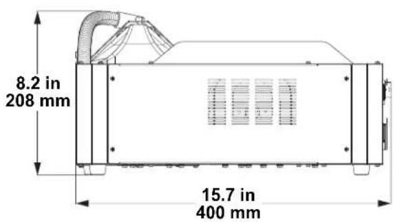
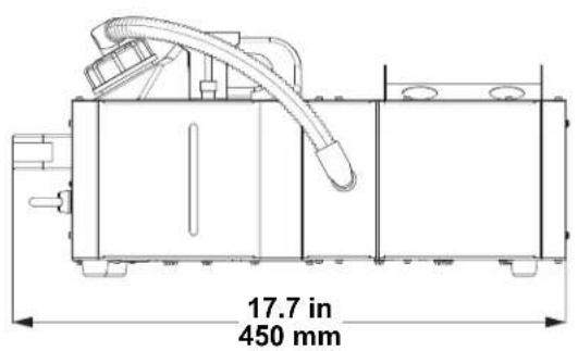
Product Dimensions
3. Setup
AC Power
The Geyser Move has a fixed voltage power supply, and it can work with an input voltage range of either 120 VAC, 60 Hz or 230 VAC, 50 Hz, depending on the specific model.
To determine the product's power requirements (circuit breaker, power outlet, and wiring), use the current value listed on the label affixed to the product's back panel, or refer to the product's specifications chart. The listed current rating indicates the product's average current draw under normal conditions.

• Always connect the product to a protected circuit (a circuit breaker or fuse). Make sure the product has an appropriate electrical ground to avoid the risk of electrocution or fire.
- To eliminate unnecessary wear and improve its lifespan, during periods of non-use completely disconnect the product from power via breaker or by unplugging it.

Never connect the product to a rheostat (variable resistor) or dimmer circuit, even if the rheostat or dimmer channel serves only as a 0 to 100% switch.
Fuse Replacement
- Disconnect the product from power.
- Wedge the tip of a flat-head screwdriver into the slot of the fuse holder.
- Pry the fuse holder out of the housing.
- Remove the blown fuse from the holder and replace with a fuse of the exact same type and rating.
- Insert the fuse holder back in place and reconnect power.


Disconnect the product from the power outlet before replacing the fuse.

Always replace a blown fuse with one of the same type and rating.

While operating the Geyser Move, make sure there is adequate fog fluid in the machine to prevent pump and heater damage. When the fog fluid level becomes low, simply add more fog fluid to continue using the Geyser Move.

Ensure the fluid tank is upright, regardless of the mounting orientation.
Mounting
Before mounting the product, read and follow the safety recommendations indicated in the Safety Notes.
Orientation
The Geyser Move may be mounted in any position; however, make sure adequate ventilation is provided around the product. In addition, make sure the fluid tank is in an upright position. See Inverting the Tank for information on mounting in other positions.
Rigging
- Before deciding on a location for the product, always make sure there is easy access to the product for maintenance and programming.
- Make sure that the structure and attachment points can support the weight before hanging the product (see the Technical Specifications)
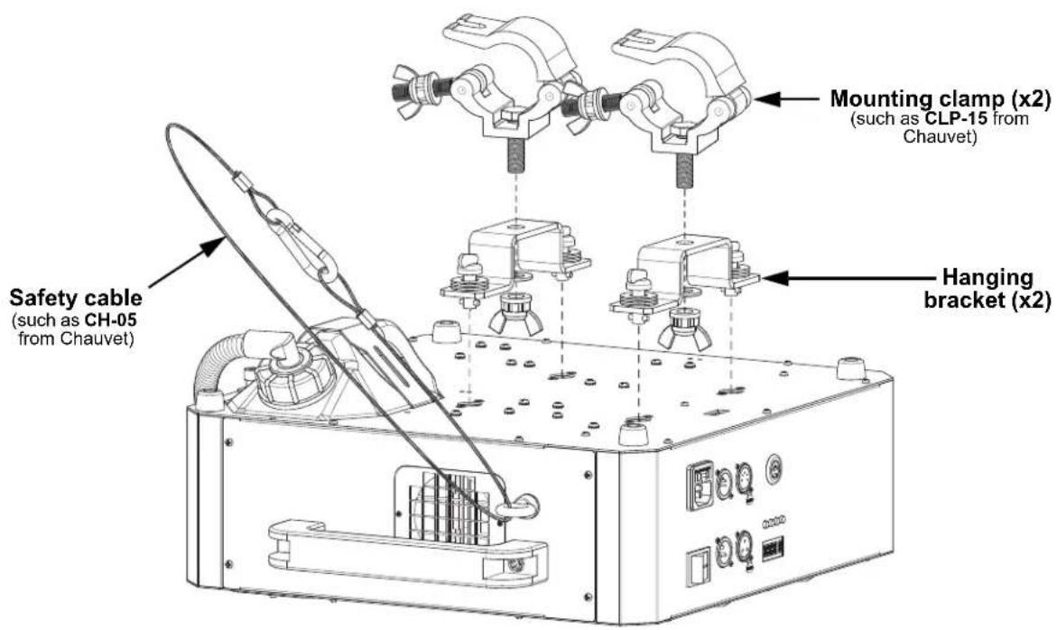
- When mounting the product overhead, always use a safety cable. Mount the product securely to a rigging point, such as an elevated platform or a truss.
- When rigging the product onto a truss, use a mounting clamp of appropriate weight capacity. The brackets have 13-mm holes, which are appropriate for this purpose.
- When mounting the product on the floor, make sure that the product and cables are away from people and vehicles.
Sideways Mounting Diagram

Inverting the Tank
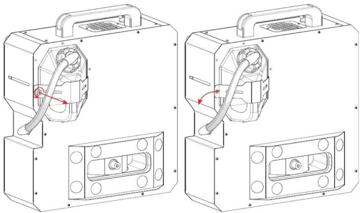
To mount the Geyser Move in a position where the fluid tank would normally not be upright, it will be necessary to invert the tank orientation.
- Remove the thumbscrew securing the fluid tank bracket, slide the bracket out and place it to the side.
natural_image
Technical line drawings of two identical industrial electrical enclosures with visible heat exchangers and internal components (no text or symbols)-
Remove the fluid tank and set it to the side.
-
Remove the tank base plate by removing four screws, and install it on the opposite side with the same four screws.

natural_image
Technical line drawings of industrial equipment components with red directional arrows indicating flow or movement (no text or symbols present)- Insert the fluid tank in the opposite side from the original position.
- Insert the fluid tank bracket in the slot and secure it with the thumbscrew.

natural_image
Technical line drawing of a mechanical device with internal components and mounting holes (no text or symbols)
natural_image
Technical line drawing of a mechanical device casing with mounting holes and internal components (no text or symbols)Inverted Mounting Diagram
4. Operation
Control Panel Operation
To access the control panel functions, use the four buttons located underneath the display. Please refer to the Product Overview to see the button locations on the control panel.
Button Function
| Press to find an operation mode or to back out of the current menu option | |
| Press to scroll up the list of options or to find a higher value | |
| Press to scroll down the list of options or to find a lower value |
Menu Map
Refer to the Geyser Move product page on www.chauvetdj.com for the latest menu map and software.
Mode Programming Levels Description
| DMX Mode | Addr 1–512 | Sets the DMX starting address | ||
| WRC Color | CH-1–4 | oFF | Sets no color output for the selected WRC button | |
| Co 1–20 | Sets the following static color(s) for the selected WRC button: | |||
| Co 1: red | Co11: zone 1 green, zone 2 red | |||
| Co 2: green | Co12: zone 1 blue, zone 2 red | |||
| Co 3: blue | Co13: zone 1 red, zone 2 green | |||
| Co 4: amber | Co14: zone 1 blue, zone 2 green | |||
| Co 5: ultraviolet | Co15: zone 1 red, zone 2 blue | |||
| Co 6: hot pink | Co16: zone 1 green, zone 2 blue | |||
| Co 7: magenta | Co17: zone 1 amber, zone 2 magenta | |||
| Co 8: yellow | Co18: zone 1 blue, zone 2 magenta | |||
| Co 9: cyan | Co19: zone 1 magenta, zone 2 amber | |||
| Co10: white | Co20: zone 1 hot pink, zone 2 blue | |||
| rAnd Sets a random color chase for the selected WRC button | ||||
| WRC Angle | dEG1–4 | 1–255 Sets the motor angle for the selected WRC button | ||
| rAnd Sets a random movement macro for the selected WRC button | ||||

After connecting power, allow 5 to 6 minutes for the Geyser Move to heat up before triggering fog output.
DMX Configuration
The Geyser Move works with a DMX controller. Information about DMX is in the Chauvet DMX Primer, which is available from the Chauvet website chauvetlighting.com/downloads/DMX_Primer_rev05_WO.pdf.
Personality and Starting Address
The Geyser Move uses 16 DMX channels in the DMX mode, which defines the highest recommended address to 497.
When selecting a starting DMX address, always consider the number of DMX channels the DMX mode uses. If the starting address is set too high, access to some channels could be restricted.
For information about the DMX protocol, download the DMX Primer from www.chauvetdj.com.
To select the personality and starting address, do the following:
- Press
- Press
. - Use
or to select the starting address, from 1–512. - Press
.
DMX Channel Assignments and Values
Zones for DMX Control

DMX Charts
| Channel | Function Value Percent/Setting | ||
| 1 Fog | 000 ⇔ 009 | No function | |
| 010 ⇔ 255 | Fog output | ||
| 2 | R e d 1 | 000 ⇔ 011 | No function |
| 012 ⇔ 255 | 0–100% | ||
| 3 | G r e e n 1 | 000 ⇔ 011 | No function |
| 012 ⇔ 255 | 0–100% | ||
| 4 | B l u e 1 | 000 ⇔ 011 | No function |
| 012 ⇔ 255 | 0–100% | ||
| 5 | A m b e r 1 | 000 ⇔ 011 | No function |
| 012 ⇔ 255 | 0–100% | ||
| 6 Ultraviolet 1 | 000 ⇔ 011 | No function | |
| 012 ⇔ 255 | 0–100% | ||
| 7 | R e d 2 | 000 ⇔ 011 | No function |
| 012 ⇔ 255 | 0–100% | ||
| 8 | G r e e n 2 | 000 ⇔ 011 | No function |
| 012 ⇔ 255 | 0–100% | ||
| 9 | B l u e 2 | 000 ⇔ 011 | No function |
| 012 ⇔ 255 | 0–100% | ||
| 10 Amber 2 | 000 ⇔ 011 | No function | |
| 012 ⇔ 255 | 0–100% | ||
| 11 Ultraviolet 2 | 000 ⇔ 011 | No function | |
| 012 ⇔ 255 | 0–100% | ||
| 12 Color macro | 000 ⇔ 009 | No function | |
| 010 ⇔ 255 | Color macros | ||
| 13 Color macro speed | 000 ⇔ 009 | No function | |
| 010 ⇔ 255 | Color macro speed, slow to fast | ||
| 14 Strobe | 000 ⇔ 009 | No function | |
| 010 ⇔ 255 | Strobe, slow to fast | ||
| 15 Dimmer | 000 ⇔ 011 | No function | |
| 012 ⇔ 255 | 0–100% | ||
| 16 Motor | 000 ⇔ 029 | No function | |
| 030 ⇔ 255 | Motor angle, -45° to +45° | ||
Geyser WRC Configuration
The included Geyser Wireless Remote Control (WRC) and receiver allows up to 4 preset colors and motor positions to be triggered from up to 100 ft (30 m) away. See the Product Overview for the location of the receiver input port.

After connecting power, allow 5 to 6 minutes for the Geyser Move to heat up before triggering fog output.
Color Selection
To configure the color output triggered by a button on the Geyser WRC (<1>-<4>), do the following:
- Press
- Press
. - Use
or to select the desired output, from:
| Option | Description Option Description | ||
| oFF | No color output | Co11 | zone 1 green, zone 2 red |
| Co 1 | Red | Co12 | zone 1 blue, zone 2 red |
| Co 2 | Green | Co13 | zone 1 red, zone 2 green |
| Co 3 | Blue | Co14 | zone 1 blue, zone 2 green |
| Co 4 | Amber | Co15 | zone 1 red, zone 2 blue |
| Co 5 | Ultraviolet | Co16 | zone 1 green, zone 2 blue |
| Co 6 | Hot pink | Co17 | zone 1 amber, zone 2 magenta |
| Co 7 | Magenta | Co18 | zone 1 blue, zone 2 magenta |
| Co 8 | Yellow | Co19 | zone 1 magenta, zone 2 amber |
| Co 9 | Cyan | Co20 | zone 1 hot pink, zone 2 blue |
| Co10 | White | rAnd | Random color chase |
- Press
.
Motor Angle Selection
To configure the motorized output nozzle position triggered by a button on the Geyser WRC (<1>-<4>), follow the instructions below:
- Press
- Press
. - Use
or to select the desired motor position, from 1–255 (-45° to +45°) or rAnd (a random movement macro). - Press
.
Geyser WRC Overview

natural_image
Line drawing of a mobile phone with antenna and keypad (no text or symbols)
Ensure the Geyser WRC has an unobstructed view of the product for maximum performance.
5. Maintenance
Product Maintenance
Dust build-up reduces light output performance and can cause overheating. This can lead to reduction of the light source's life and/or mechanical wear. To maintain optimum performance and minimize wear, clean all lighting products at least twice a month. However, be aware that usage and environmental conditions could be contributing factors to increase the cleaning frequency.
To clean the product, follow the instructions below:
- Unplug the product from power.
- Wait until the product is at room temperature.
- Use a vacuum (or dry compressed air) and a soft brush to remove dust collected on the external surface/vents.
- Clean all transparent surfaces with a mild soap solution, ammonia-free glass cleaner, or isopropyl alcohol.
- Apply the solution directly to a soft, lint free cotton cloth or a lens cleaning tissue.
- Softly drag any dirt or grime to the outside of the transparent surface.
- Gently polish the transparent surfaces until they are free of haze and lint.

Always dry the transparent surfaces carefully after cleaning them.

Do not spin the cooling fans using compressed air because they could be damaged.
Fog Machine Maintenance
Do not allow the fog machine to become clogged. After every 40 hours of continuous operation, use Chauvet Fog Cleaner Quart (FCQ) through the system to prevent the accumulation of particulate matter in the heating element.
The recommended cleaning procedure is as follows.
- Unplug the product from power.
- Empty all fog fluid from the machine.
- Add cleaning solution to the tank.
- Connect the product to power and allow it to warm up.
- Run the unit in a well-ventilated area until the tank is almost empty. Do not allow the pump to run dry.
- Refill with fog fluid to continue using the fog machine. Run the machine briefly to clear any remaining cleaning solution from the pump and heater.

Do not operate the machine without fluid at any time.

Fog Cleaner Quart (FCQ) was specifically developed by Chauvet to clean the Geyser Move. Use FCQ regularly, no longer than 90 days between cleanings, to increase the life of the product.
Storage
Before storing the fog machine, run FCQ through the system as described in the cleaning procedure above; however, only follow steps 1 through 5. Do not refill the tank with fog fluid if storing the Geyser Move. Cleaning the system prior to storage will help prevent any particles from condensing inside the pump or heater while not in use.

Test-run the Geyser Move on a monthly basis to achieve the best performance.
6. Technical Specifications
Dimensions and Weight
Length Width Height Weight
8.2 in (208 mm) 15.7 in (400 mm) 17.7 in (450 mm) 24.6 lb (11.1 kg)
Note: Dimensions in inches are rounded.
Power
| Power Supply Type Range Voltage Selection | ||
| Model-specific | 120 VAC, 60 Hz or 230 VAC, 50 Hz | Fixed |
| Parameter 120 V, 60 Hz 230 V, 50 Hz | ||
| Consumption 1,240 W 1,240 W | ||
| Operating Current | 11 A | 5.5 A |
| Fuse | F15 A, 250 V | F15 A, 250 V |
| Power I/O | U.S./Worldwide | UK/Europe |
| Power input connector | IEC | IEC |
| Power output connector Edison | IEC | |
| Power cable plug Edison (U.S.) Local Plug | ||
Operation
| Heat-Up Time | Tank Capacity | Fluid Consumption | Fog Output |
| 5 min | 0.6 gal (2.4 l) | 62.5 ml/min | 17,000 cfm |
Light Source
| Type | Color | Quantity | Power | Current | Lifespan |
| LED | Penta-color RGBA+UV | 8 | 10 W | 2.5 A | 50,000 hours |
Photometrics
| Strobe Rate | Beam Angle | Illuminance @ 2 m |
| 0 to 20 Hz | 57° | 595 lux |
Thermal
| Maximum External Temperature | Cooling System |
| 104 °F (40 °C) | Fan-assisted convection |
DMX
| I/O Connector Channel Range | |
| 3- and 5-pin XLR | 16 |
Ordering
| Product Name | Item Code | UPC Number |
| Geyser Move (120 V) 05072303 | 781462226510 | |
| Geyser Move (230 V) 05072306 | 781462226541 |



RoHS

Contact Us
General Information Technical Support
Chauvet World Headquarters
Address: 3360 Davie Rd., Suite 509 Voice: (844) 393-7575
Davie, FL 33314 Fax: (954) 756-8015
Voice: (954) 577-4455 Email: chauvetcs@chauvetlighting.com
Fax: (954) 929-5560
Toll Free: (800) 762-1084 Website: www.chauvetdj.com
Chauvet U.K.
Address: Pod 1 EVO Park Email: UKtech@chauvetlighting.eu
Little Oak Drive, Sherwood Park
Nottinghamshire, NG15 0EB Website: www.chauvetdj.eu
UK
Voice: +44 (0) 1773 511115
Fax: +44 (0) 1773 511110
Chauvet Benelux
Address: Stokstraat 18 Email: BNLtech@chauvetlighting.eu
9770 Kruishoutem
Belgium Website: www.chauvetdj.eu
Voice: +32 9 388 93 97
Chauvet France
Address: 3, Rue Ampère Email: FRtech@chauvetlighting.fr
91380 Chilly-Mazarin
France Website: www.chauvetdj.eu
Voice: +33 1 78 85 33 59
Chauvet Germany
Address: Bruno-Bürgel-Str. 11 Email: DEtech@chauvetlighting.de
28759 Bremen
Germany Website: www.chauvetdj.eu
Voice: +49 421 62 60 20
Chauvet Mexico
(Entrance by Calle 2)
Zona Industrial Lerma
Website: www.chauvetdj.mx
For warranty terms and conditions and return information, please visit our website.
For customers in the United States and Mexico: www.chauvetlighting.com/warranty-registration.
For customers in the United Kingdom, Republic of Ireland, Belgium, the Netherlands, Luxembourg,
France, and Germany: www.chauvetlighting.eu/warranty-registration.
- Edition Notes
- Trademarks
- Copyright Notice
- Manual Use
- Document Printing
- Intended Audience
- Disclaimer
- Document Revision
- TABLE OF CONTENTS
- Before You Begin .... 1
- Introduction...... 4
- Setup.... 5
- Operation.... 9
- Maintenance.... 12
- Technical Specifications.... 13
- Contact Us.... 14
- Before You Begin
- What Is Included
- Unpacking Instructions
- Claims
- Text Conventions
- Symbols
- Safety Notes
- ■ ALWAYS:
- FCC Statement of Compliance
- RF Exposure Warning for North America and Australia
- Introduction
- # Name
- Setup
- AC Power
- Fuse Replacement
- Mounting
- Orientation
- Rigging
- Inverting the Tank
- Operation
- Control Panel Operation
- Menu Map
- DMX Configuration
- Personality and Starting Address
- DMX Channel Assignments and Values
- Zones for DMX Control
- Geyser WRC Configuration
- Color Selection
- Motor Angle Selection
- Geyser WRC Overview
- Maintenance
- Product Maintenance
- Fog Machine Maintenance
- Storage
- Technical Specifications
- Dimensions and Weight
- Length Width Height Weight
- Contact Us
- General Information Technical Support
- Chauvet World Headquarters
- Chauvet U.K.
- Chauvet Benelux
- Chauvet France
- Chauvet Germany
- Chauvet Mexico
Brand : Chauvet
Model : Geyser Move
Category : Smoke machine