
TA-4.450 - Receiver DAP-Audio - Free user manual and instructions
Find the device manual for free TA-4.450 DAP-Audio in PDF.


| Product Type | Receiver |
| Brand | DAP-Audio |
| Model | TA-4.450 |
| Dimensions (W x H x D) | 483 x 44 x 200 mm (19" rack mount, 1U) |
| Weight | Approx. 2.5 kg |
| Power Supply | AC 100-240V, 50/60Hz |
| Power Consumption | Max. 30W |
| Frequency Range | 640 - 690 MHz (UHF) |
| Number of Channels | 4 (quad receiver) |
| Audio Output | XLR balanced and 6.3mm unbalanced jack |
| Antenna Input | 2 BNC connectors with DC bias for active antennas |
| Display | LCD with RF and AF level meters |
| Controls | Power switch, volume control, IR sync button |
| Mounting | 19" rack mount, 1U height |
| Operating Temperature | 0°C to 40°C |
| Maintenance | Clean exterior with dry cloth; avoid liquids; check antennas regularly |
| Safety | Use only included power adapter; avoid exposure to rain or moisture |
| Spare Parts | Contact authorized service center for replacement antennas, power supplies, and mounting brackets |
| General Information | Professional UHF wireless receiver for simultaneous use of up to 4 microphones; suitable for stages and conferences |
Frequently Asked Questions - TA-4.450 DAP-Audio
User questions about TA-4.450 DAP-Audio
0 question about this device. Answer the ones you know or ask your own.
Ask a new question about this device
Download the instructions for your Receiver in PDF format for free! Find your manual TA-4.450 - DAP-Audio and take your electronic device back in hand. On this page are published all the documents necessary for the use of your device. TA-4.450 by DAP-Audio.
USER MANUAL TA-4.450 DAP-Audio
natural_image
Front view line drawing of a server rack unit with ports and connectors (no text or symbols)TA-4.450
Product code: D4220
4-channel 450W amp with DSP
Preface
Thank you for purchasing this DAP product.
The purpose of this user manual is to provide instructions for the correct and safe use of this product.
Keep the user manual for future reference as it is an integral part of the product. The user manual shall be stored at an easily accessible location.
This user manual contains information concerning:
- Safety instructions
- Intended and non-intended use of the device
• Installation and operation of the device - Maintenance procedures
- Troubleshooting
- Transport, storage and disposal of the device
Non-observance of the instructions in this user manual may result in serious injuries and damage of property.
©2025 DAP. All rights reserved.
No part of this document may be copied, published or otherwise reproduced without the prior written consent of Highlite International.
Design and product specifications are subject to change without prior notice.
For the latest version of this document or other language versions, please visit our website www.highlite.com or contact us at service@highlite.com.
Highlite International and its authorized service providers are not liable for any injury, damage, direct or indirect loss, consequential or economic loss or any other loss arising from the use of, or inability to use or reliance on the information contained in this document.
Highlite International B.V. – Vestastraat 2 – 6468 EX Kerkrade – the Netherlands
Table of contents
1. Introduction......4
1.1. Before Using the Product....4
1.2. Intended Use.... 4
1.3. Text Conventions....4
1.4. Symbols and Signal Words.... 5
1.5. Symbols on the Information Label 5
2. Safety 6
2.1. Warnings and Safety Instructions....6
2.2. Requirements for the User 8
3. Description of the Device....8
3.1. Front View 8
3.2. Back View 8
3.3. Product Specifications....9
3.4. Dimensions.... 11
3.5. Optional Accessories and Software.... 11
4. Installation.... 12
4.1. Safety Instructions for Installation.... 12
4.2. Installation Site Requirements.... 12
4.3. Rack Mounting.... 12
4.4. Connecting to Power Supply 12
5. Setup....13
5.1. Setup in Stereo Mode 13
5.2. Setup in Bridge Mode 14
5.3. Connecting Multiple Devices.... 15
6. Operation....16
6.1. Safety Instructions for Operation.... 16
6.2. Switching On and Off 16
6.3. Control Modes....16
6.4. Start-up....16
6.5. Menu Overview.... 17
6.6.Main Menu Options....17
6.6.1. Preset.... 18
6.6.2. Volume 18
6.6.3. AMP Mode 18
6.6.4. Settings.... 19
6.6.5. Monitor 19
6.6.6. Info....19
6.7. Control Software....20
6.7.1. Device List.... 20
6.7.2. Groups Menu.... 21
6.7.2.1. Groups Set.... 21
6.7.2.2. Group Settings 22
6.7.3. Main Control Interface 22
6.7.3.1. Volume 23
6.7.3.2. Output 23
6.7.4. Input Menu 24
6.7.4.1. Source Screen 24
6.7.4.2. Input Equalizer.... 25
6.7.4.3. Audio Routing and Mixing.... 26
6.7.5. Output Menu 26
6.7.5.1. Voltage Limiter 27
7.6. Preset Menu.... 27
6.7.6.1. Speaker Configuration Menu 28
6.7.6.2. Device Mirror Menu.... 29
7. Troubleshooting....30
8. Maintenance.... 30
8.1. Safety Instructions for Maintenance.... 30
8.2. Preventive Maintenance.... 30
8.2.1. Basic Cleaning Instructions.... 30
8.2.2. Cleaning the Cooling Vents.... 31
8.3. Corrective Maintenance.... 31
- Deinstallation, Transportation and Storage 32
9.1. Instructions for Deinstallation.... 32
9.2. Instructions for Transportation.... 32
9.3. Storage.... 32
-
Disposal 32
-
Approval.... 32
1. Introduction
1.1. Before Using the Product

Important
Read and follow the instructions in this user manual before installing, operating or servicing this product.
The manufacturer will not accept liability for any resulting damages caused by the non-observance of this manual.
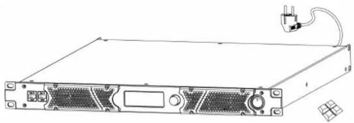
After unpacking, check the contents of the box. If any parts are missing or damaged, contact your Highlite International dealer.
Your shipment includes:
Figure 1
- DAP TA-4.450
- User manual
• 4x adhesive rubber feet •
natural_image
Line drawing of a server rack with ports, connectors, and a cable (no text or symbols)1.2. Intended Use
This device is intended for professional use as an amplifier. It can be installed only indoors. This device is not suitable for households.
Any other use, not mentioned under intended use, is regarded as non-intended and incorrect use.
1.3. Text Conventions
Throughout the user manual the following text conventions are used:
- Buttons: All buttons are in bold lettering, for example "Press the UP/DOWN buttons"
- References: References to parts of the device are in bold lettering, for example: "turn the adjustment handle (05)". References to chapters are hyperlinked
• 0–255: Defines a range of values• - Notes: Note: (in bold lettering) is followed by useful information or tips
1.4. Symbols and Signal Words
Safety notes and warnings are indicated throughout the user manual by safety signs.
Always follow the instructions provided in this user manual.

DANGER
Indicates an imminently hazardous situation which, if not avoided, will result in death or serious injury.
WARNING
Indicates a potentially hazardous situation which, if not avoided, could result in death or serious injury.
CAUTION
Indicates a potentially hazardous situation, which, if not avoided, may result in minor or moderate injury.
Attention Indicates important information for the correct operation and use of the product.
Important Read and observe the instructions in this document.
Electrical hazard
Provides important information about the disposal of this product.
1.5. Symbols on the Information Label
This product is provided with an information label. The information label is located on the side of the device.
The information label contains the following symbols:

This device is designed for indoor use.
This device shall not be treated as household waste.
This device falls under IEC protection class I.
2. Safety

Important
Read and follow the instructions in this user manual before installing, operating or servicing this product.
The manufacturer will not accept liability for any resulting damages caused by the non-observance of this manual.
2.1. Warnings and Safety Instructions

DANGER
Danger for children
For adult use only. The device must be installed beyond the reach of children.
- Do not leave any parts of the packaging (plastic bags, polystyrene foam, nails, etc.) within the reach of children. Packaging material is a potential source of danger for children.

DANGER
Electric shock caused by dangerous voltage inside
There are areas inside the device where dangerous touch voltage may be present.
- Do not open the device or remove any covers.
- Do not operate the device if the covers or the housing are open. Before operation, check if the housing is firmly closed and all screws are tightly fastened.
- Disconnect the device from the electrical power supply before service and maintenance, and when the device is not in use.

DANGER
Electric shock caused by short-circuit
This device falls under IEC protection Class I.
- Make sure that the device is electrically connected to ground (earth). Connect the device only to a socket-outlet with a ground (earth) connection.
- Do not cover the ground (earth) connection.
- Do not bypass the thermostatic switch or fuses.
- Do not let the power cable come into contact with other cables. Handle the power cable and all connections with the mains with caution.
- Do not modify, bend, mechanically strain, put pressure on, pull or heat up the power cable.
- Make sure that the power cable is not crimped or damaged. Examine the power cable periodically for any defects.
- Do not immerse the device in water or other liquids. Do not install the device in a location where flooding may occur.
- Do not use the device during thunderstorms. Disconnect the device from the electrical power supply immediately.

Attention Power supply
- Before connecting the device to the power supply, make sure that the current, voltage and frequency match the input voltage, current and frequency specified on the information label on the device.
- Make sure that the cross-sectional area of the extension cords and power cables is sufficient for the required power consumption of the device.

Attention General safety
- Do not block the ventilation openings. Without proper heat dissipation and air circulation, the internal components may overheat. This can result in product damage.
- Do not shake the device. Avoid brute force when installing or operating the device.
- If the device is dropped or struck, disconnect the device from the electrical power supply immediately.
- If the device is exposed to extreme temperature variations (e.g. after transportation), do not switch it on immediately. Let the device reach room temperature before switching it on, otherwise it may be damaged by the formed condensation.
- If the device fails to work properly, discontinue use immediately.

Attention For professional use only This device must be used only for the purposes it is designed for.
This device is designed to be used as an amplifier. Any incorrect use may lead to hazardous situations and result in injuries and material damage.
• This device is not suitable for households.
- This device does not contain user-serviceable parts. Unauthorized modifications to the device will render the warranty void. Such modifications may result in injuries and material damage.

Attention Before each use, examine the device visually for any defects.
Make sure that:
- All screws used for installing the device or parts of the device are tightly fastened and are not corroded.
- There are no deformations on housings, fixings and installation points.
- The power cables are not damaged and do not show any material fatigue.

Attention Do not expose the device to conditions that exceed the rated IP class conditions.
This device is IP20 rated. IP (Ingress Protection) 20 class provides protection against solid objects greater than 12 mm, such as fingers, and no protection against harmful ingress of water.
2.2. Requirements for the User
This product may be used by ordinary persons. Maintenance may be carried out by ordinary persons. Installation and service shall be carried out only by instructed or skilled persons. Contact your Highlite International dealer for more information.
Instructed persons have been instructed and trained by a skilled person, or are supervised by a skilled person, for specific tasks and work activities associated with the installation, service and maintenance of this product, so that they can identify risks and take precautions to avoid them.
Skilled persons have training or experience, which enables them to recognize risks and avoid hazards associated with the installation, service and maintenance of this product.
Ordinary persons are all persons other than instructed persons and skilled persons. Ordinary persons include not only users of the product but also any other persons that may have access to the device or who may be in the vicinity of the device.
3. Description of the Device
The DAP TA-4.450 is a 4-channel DSP power amplifier for touring applications. It delivers 4x 450 W into 4 Ω. It is capable of driving 2 Ω loads and can be bridged for more power.
The DSP can be controlled via a network connection and PC software (Windows 10/11). It offers input delays of up to 100 ms, output delays of up to 20 ms, +/- 18 dB level matching, 4x4 audio route mixing, 8-band parametric input and output equalizers, high and low pass filters, FIR filters with up to 512 taps, peak and RMS limiters, phase control and more. The amplifier supports IP and output voltage/current, temperature and protection can be monitored over the network. The built-in switch allows the network to be daisy-chained to multiple amplifiers. The LCD screen shows status and settings, which can be adjusted using the rotary knob.
3.1. Front View
Figure 2

01) 4x mounting openings (for installation in a 19-inch rack)
02) Primary Ethernet RJ45 connector
03) Secondary Ethernet RJ45 connector
04) 2x cooling vent covers
05) Control panel: LCD display
06) Control knob
07) Power switch
3.2. Back View
Figure 3

10) 4x 3-pin XLR connectors IN
3.3. Product Specifications
Model: TA-4.450
Inputs:
| Mono inputs 4 |
| Transformer N/A V |
| Mono input connector 3-pin XLR |
| Mono input gain range 21 dB |
| Mono input impedance 20.000 Ω |
Outputs:
| 2 ohms stable Yes | |
| Output per channel into 8 ohms at 1 kHz 250 W | |
| Output per channel into 4 ohms at 1 kHz 450 W | |
| Output per channel into 2 ohms at 1 kHz 700 W | |
| Bridge output into 8 ohms at 1 kHz 850 W | |
| Bridge output into 4 ohms at 1 kHz 1450 W | |
| Output channels 4 | |
| Output mode 4-channel / Bridge / Mono / Parallel / Stereo | |
| Output connector Speaker connector 4 pole | |
Audio specifications:
| THD level < 0,05 % | |
| Signal-to-noise ratio > 100 dB | |
| Slew rate 50 V/μs | |
| Amp technology Class D | |
| Damping factor | 1000 :1 |
| Crosstalk | 90 dBu |
| Frequency response minimum | 20 Hz |
| Frequency response maximum | 20.000 Hz |
Software specifications:
Supported operating systems Windows 10 / Windows 11
Sound editing:
| Parametric input equalizer | 8 bands |
| Parametric output equalizer | 8 bands |
| Input equalizer types | High shelf / Low shelf |
| Crossover filter types | Bessel / Butterworth / Linkwitz Riley |
| Crossover slopes | 6 / 12 / 24 / 48 dB |
| Dynamics processing | Limiter |
| Limiter attack time minimum | 1 ms |
| Limiter attack time maximum | 2000 ms |
| Limiter release time minimum | 20 ms |
| Limiter release time maximum | 1000 ms |
| Output delay (max.) | 30 ms |
| Input delay (max.) | 100 ms |
Internal storage:
| User presets Yes | |
| User presets capacity 40 |
Control and programming:
| Control mode PC software | |
| Display LCD | |
| Display size 3" |
Electrical specifications and connections:
| Power supply 100–240 V AC 50/60 Hz | |
| SMPS Yes | |
| Power consumption 420 W | |
| Power connector in Schuko plug | |
| Data connector in RJ45 |
Mechanical specifications:
| Amplifier airflow Front to back | |
| Amplifier cooling Axial fan | |
| Height 45 mm | |
| Width 483 mm | |
| Depth 385 mm | |
| Installation depth (excl. connector) 385 mm | |
| Flightcase size | 19" |
| Rack units | 1 U |
| Housing | Steel |
| Color | Black |
| Finish Powder coating | |
| Weight 8 kg | |
| IP rating | IP20 (indoor use only) |
Product properties:
| Handles | No |
| Electronic protection | Clip limiter / DC voltage / Overheat / Overload / Under voltage |
Thermal specifications:
| Maximum ambient temperature | 40 °C |
| Minimum ambient temperature | -15 °C |
| Maximum surface temperature | 70 °C |
Included items:
| Included cables | Fixed cable |
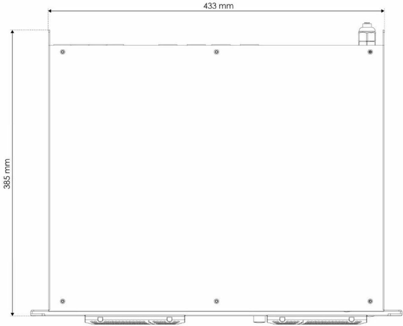
3.4. Dimensions
Figure 4

other
| Dimension | Value | | --------- | ----- | | Top Width | 433 mm | | Bottom Width | 385 mm |3.5. Optional Accessories and Software
You can download the control software for the TA-4.450 from the Highlite International website:
• D4220 Control software
4. Installation
4.1. Safety Instructions for Installation

Attention
Make sure that there is enough space for ventilation around the device.
- Do not block the ventilation openings. Without proper heat dissipation and air circulation, the internal components may overheat. This can result in product damage.
- Do not install near equipment that produces heat, for example amplifiers.
4.2. Installation Site Requirements
• The device can be used only indoors.
• The minimum distance to other objects must be bigger than 0,5 m.
- The maximum ambient temperature t_a = 40^ must never be exceeded.
• The relative humidity must not exceed 50 % with an ambient temperature of 40 °C.
4.3. Rack Mounting
The device can be placed on a stable, flat surface using the adhesive feet, or mounted in a standard 19-inch rack. The device requires 1 rack unit (RU) of space.
Make sure that the rack is sufficiently secured to prevent it from becoming unstable or falling over.
To mount the device in a two-post rack, follow the steps below:
01) Insert 4 cage nuts in the openings on the rack posts where you want to mount the device.01)
02) Position the device in front of the rack posts so that the 4 mounting openings (01) on the flanges face the openings on the rack posts with cage nuts.
03) Use a screwdriver to mount the device to the rack posts with 4 screws.03)
4.4. Connecting to Power Supply

DANGER
Electric shock caused by short-circuit
The device accepts AC mains power at 100–240 V and 50/60 Hz. Do not supply power at any other voltage or frequency to the device.
This device falls under IEC protection class I. Make sure that the device is always electrically connected to the ground (earth).
Before connecting the device to the socket-outlet:
- Make sure that the power supply matches the input voltage specified on the information label on the device.
- Make sure that the socket-outlet has ground (earth) connection.
Connect the device to the socket-outlet with the power plug. Do not connect the device to a dimmer circuit, as this may damage the device.
5. Setup
The TA-4.450 can be set up in stereo mode or bridge mode to change how the inputs are connected to the outputs. The mode can be changed through the control panel (see 6.6.3. AMP Mode on page 18) or the control software (see 6.7.5. Output Menu on page 26).
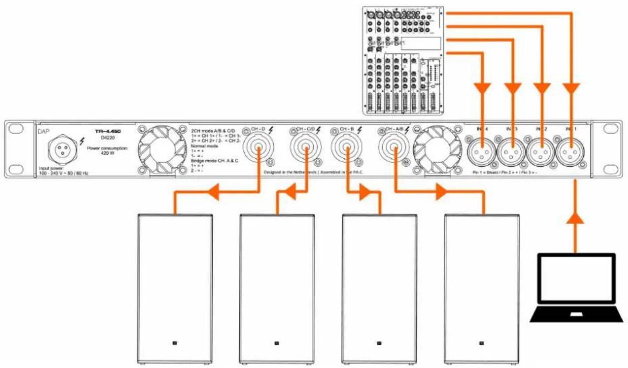
5.1. Setup in Stereo Mode
You can set up the TA-4.450 in stereo mode to connect 4 inputs to 4 outputs.
To complete the setup, follow the steps below:
01) Make sure that all devices are switched off.01)
02) Connect the PC to the primary Ethernet RJ45 connector (02). Use an Ethernet cable (minimum CAT-5).
03) Connect the input devices to the 3-pin XLR connectors IN (10).03)
04) Connect the speaker connectors OUT (09) of to the speakers.04)
05) Switch on all devices.05)
06) Adjust the amplifier settings with the control software (see 6.7. Control Software on page 20) or with the control knob (06) (see 6.6. Main Menu Options on page 17).
Figure 5
flowchart
graph TD
    A["Input power 100 - 240 V ~ 50 / 80 Hz"] --> B["DAP"]
    B --> C["TR-4.450 D4220"]
    B --> D["Power consumption: 420 W"]
    B --> E["2CH mode A/B & CD 1+ = CH 1+ / 1- = CH 1- 2+ = CH 2+ / 2- = CH 2- Normal mode 1= + 1- = -<br>Bridge mode Cht. A & C 1+ = +<br>2- = -"]
    B --> F["CH-D"]
    B --> G["CH-CD"]
    B --> H["CH-B"]
    B --> I["CH-A/B"]
    B --> J["IN-4 Pin 1 + Brass / Pin 2 + / Pin 3 + -"]
    B --> K["IN-3 Pin 2"]
    B --> L["IN-2 Pin 1"]
    B --> M["IN-1 Pin 1"]
    B --> N["Laptop"]
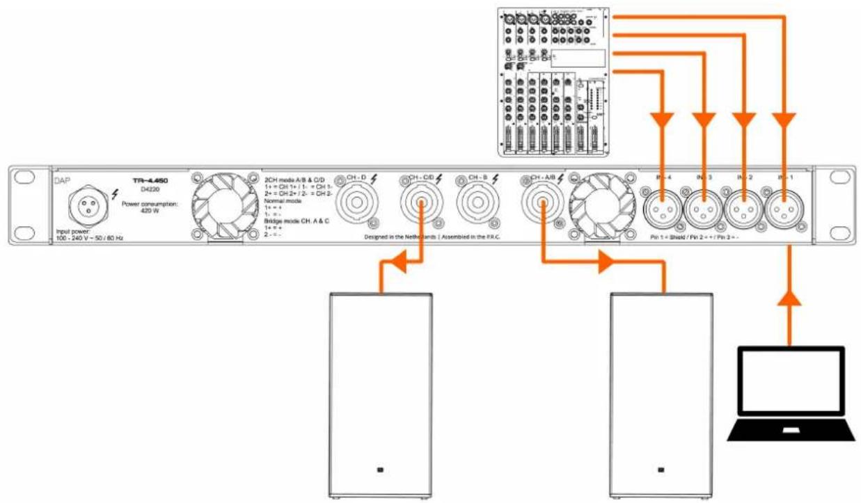
5.2. Setup in Bridge Mode
You can set up the TA-4.450 in bridge mode to connect 4 inputs to 2 outputs. You can bridge input 1 and 2 to output A and input 3 and 4 to output C.
To complete the setup, follow the steps below:
01) Make sure that all devices are switched off.01)
02) Connect the PC to the primary Ethernet RJ45 connector (02). Use an Ethernet cable (minimum CAT-5).
03) Connect the input devices to any of the 3-pin XLR connectors IN (10).03)
04) Connect the A/B and C/D speaker connectors OUT (09) to the speakers.
05) Switch on all devices.
06) Adjust the amplifier settings with the control software (see 6.7. Control Software on page 20) or with the control knob (06) (see 6.6. Main Menu Options on page 17).
Figure 6
flowchart
graph TD
    A["Input power: 100 - 240 V ~ 50 / 60 Hz"] --> B["DAP"]
    B --> C["TR-4.450 D4220"]
    C --> D["Power consumption: 420 W"]
    D --> E["2CH mode A/B & C/D"]
    E --> F["1+ = CH 1+ / 1- = CH 3-"]
    E --> G["2+ = CH 2+ / 2- = CH 2-"]
    E --> H["Normal mode"]
    H --> I["1= +"]
    H --> J["1= +"]
    H --> K["Bridge mode CH: A & C"]
    K --> L["1= +"]
    K --> M["2= +"]
    N["Designed in the Netherlands | Assembled in the FR-C"] --> O["Ch - D"]
    N --> P["Ch - CB"]
    N --> Q["Ch - B"]
    R["Pin 1 + Shield / Pin 2 + / Pin 3 +"] --> S["Ch - AB"]
    T["Laptop"] --> U["Pin 1"]
5.3. Connecting Multiple Devices
Multiple TA-4.450 devices can be operated with the same PC software. For this, a router must be used that automatically assigns IP addresses. Each TA-4.450 can be connected to the router directly, or the TA-4.450 devices can be connected in a daisy chain.
To connect multiple devices, follow the steps below:
01) Connect the PC to the router. Use an Ethernet cable.01)
02) Connect the router to the primary ethernet RJ45 connector (02) of the 1 ^st device. Use an Ethernet cable02) (min. CAT-5).
03) Connect the secondary Ethernet RJ45 connector (03) of the 1 ^st device to the primary Ethernet RJ4503) connector (02) of the 2 ^nd device. Use an Ethernet cable (min. CAT-5).
04) Repeat step 3 to connect all devices in a daisy chain.04)
05) Adjust the amplifier settings for every TA-4.450 individually from the Device list (see 6.7.1. Device List on page 20) or create a group for all devices in the Groups menu (see 6.7.2. Groups Menu on page 21).
Figure 7
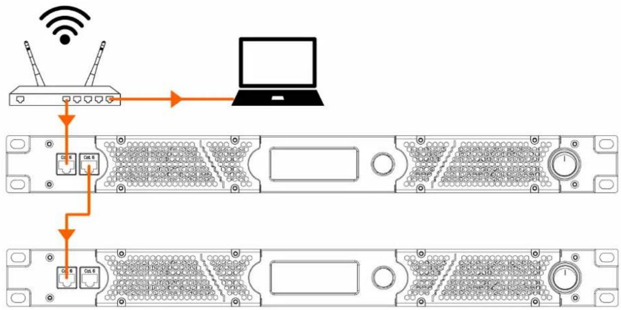
flowchart
graph TD
    A["Router"] -->|Wireless Signal| B["Laptop"]
    B --> C["Server Rack 1"]
    B --> D["Server Rack 2"]
    style A fill:#f9f,stroke:#333
    style B fill:#ccf,stroke:#333
    style C fill:#cfc,stroke:#333
    style D fill:#fcc,stroke:#333
Note:
For a stable connection, a cable connection is always recommended.
6. Operation
6.1. Safety Instructions for Operation

Attention This device must be used only for the purposes it is designed for.
This device is intended for professional use as an amplifier. It can be used only indoors. This device is not suitable for households.
Any other use, not mentioned under intended use, is regarded as non-intended and incorrect use.

Attention Power supply
Before connecting the device to the power supply, make sure that the current, voltage and frequency match the input voltage, current and frequency specified on the information label on the device.
6.2. Switching On and Off
The device has a power switch.
• To switch the device on, press the power switch (06) in ON position.
• To switch the device off, press the power switch (06) in OFF position.
6.3. Control Modes
The TA-4.450 can be operated with the PC software or with the control panel (05) and control knob (06).
- To operate the device with the control panel (05) and control knob (06), refer to Main Menu Options (see 6.6. Main Menu Options on page 17).
- To operate the device with the PC software, refer to Control Software (see 6.7. Control Software on page 20).
6.4. Start-up
Upon start-up the display shows a splash screen with DAP:

Immediately afterwards, the display shows the main screen. The main screen displays the volume/output level of each channel, the operating temperature, the current preset and the network connection status.
![Digital Audio Power Amplifier CHA: +0.0dB CHB: +0.0dB CHC: +0.0dB CHD: +0.0dB 29.3°C [ Null ]](/content/2026/05/913301/images/5c5c7bb38297f95efed6c0c24cd15777668352f4fb04c000eb851e50bfe72933.jpg)
01) Turn the control knob (06) to adjust the output level for all channels.01)
02) Press the control knob (06) to open the Main menu (see 6.6. Main Menu Options on page 17).
6.5. Menu Overview
Level 1 Level 2 Level 3
| 1. Preset (see6.6.1.Preseton page 18) 40 presets | ||
| 2. Volume (see6.6.2.Volumeon page 18) | ||
| 3. AMP Mode (see6.6.3.AMP Modeon page 18) | OutA | 1.Bridge |
| 2.Low-Z | ||
| OutB 1.Low-Z | ||
| OutC | 1.Bridge | |
| 2.Low-Z | ||
| OutD 1.Low-Z | ||
| 4. Settings (see6.6.4.Settingson page 19) | Standby | Normal |
| Standby | ||
| Contrast 30-100 | ||
| Backlight | Always | |
| Saving | ||
| OFF | ||
| IP Mode | User-set | |
| Auto-DHCP | ||
| Amp IP IP Setting | ||
| Factory Reset | NO | |
| YES | ||
| 5. Monitor (see6.6.5.Monitoron page 19) | ||
| 6. Info (see6.6.6.Infoon page 19) |
6.6. Main Menu Options
The main menu has the following options:
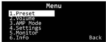
01) Turn the control knob (06) to navigate through the menu.01)
02) Press the control knob (06) to open a submenu.02)
- Preset
- Volume
- AMP Mode
- Settings
- Monitor
- Info
6.6.1. Preset
In this menu you can select one of the 40 programmable presets and view the currently active preset. The presets can be defined through the PC software (see 6.7.6. Preset Menu on page 27).
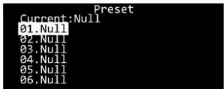
01) Turn the control knob (06) to navigate through the presets.01)
02) Press the control knob (06) to select a preset.02)
03) Scroll to the end of the list of presets and select Back to go back to the main menu.03)
6.6.2. Volume
In this menu you can change the volume of each output channel, mute channels and activate a noise gate.
01) Turn the control knob (06) to select the following 3 options for each channel:01)
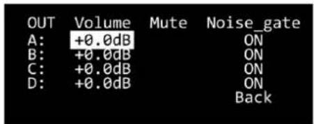
• Volume: Change the volume of the channel
- Mute: Mute the channel
- Noise_gate: Turn a noise gate on or off
02) Press the control knob (06) to select the setting.02)
03) Turn the control knob (06) to change the setting.03)
04) Press the control knob (06) to confirm the setting.04)
6.6.3. AMP Mode
In this menu you can bridge the output channels and change the amplifier mode for each output channel.
01) Turn the control knob (06) to go through the options:
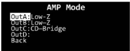
- Low-Z: Set the impedance to a lower range (all 4 channels)
- AB-Bridge:
- CD-Bridge:
Bridge the output of channel A to channel B (channel A)
Bridge the output of channel C to channel D (channel C)
02) Press the control knob (06) to select the setting.02)
03) Turn the control knob (06) to change the setting.03)
04) Press the control knob (06) to confirm the setting.04)
6.6.4. Settings
In this menu you can adjust general settings for the device.
01) Turn the control knob (06) to select one of the following 6 options:01)
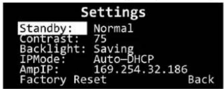
- Standby: Put the amplifier in normal or standby mode
- Contrast: Adjust the contrast of the screen. The range is 30–100 and the default value is 75•
- Backlight: The backlight of the screen can be set to Always, Saving (the backlight turns off after 2 minutes) or OFF
- IPMode: Set the IP mode to User-set to manually change the AmplIP. Set the IP mode to Auto-DHCP to automatically acquire an IP address
- AmplIP: Manually set the IP address if the IP mode is set to User-set
- Factory Reset: Reset the device to the default factory settings
02) Press the control knob (06) to select the setting.
03) Turn the control knob (06) to change the setting.
04) Press the control knob (06) to confirm the setting.
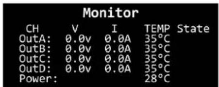
6.6.5. Monitor
In this menu you can view the output voltage, output current, operating temperature and protection state for each channel. You can also view the operating temperature for the power module of the device.
01) Press the control knob (06) to go back to the main menu.
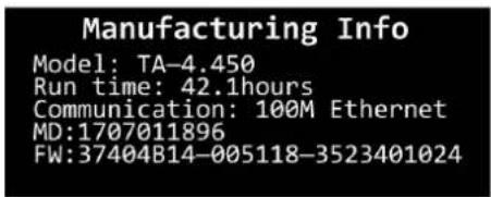
6.6.6. Info
In this menu you can view general info about the device. It shows the model name, the total working time, the communication interface type, the factory serial number and the firmware version number.
01) Press the control knob (06) to go back to the main menu.
6.7. Control Software
The TA-4.450 can be controlled through the AMP Controller software (see 3.5. Optional Accessories and Software on page 11).
01) Download and install the software.01)
02) Link one or more devices to your PC using an ethernet cable (minimum Cat. 5).02)
03) Open the software to control your linked devices.03)
6.7.1. Device List
Figure 8
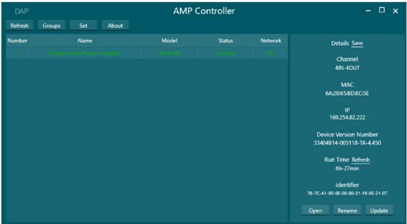
This screen shows a list of connected amplifiers, with the assigned name, the model number, the operation status (Normal, Standby, Fault, Warning), and the network connection status (ON, OFF).
The buttons on the top ribbon have the following functions:
- Refresh: Refresh the list of amplifiers
- Groups: Open the Groups screen to configure and control input channel groups (see 6.7.2. Groups Menu on page 21)
- Set: Change the permissions level, application language and layout theme for the software
- About: View the full name and version number of the software
Select an amplifier in the list to view its details on the right. These details can be saved in a .txt file.
You can do the following for each amplifier in the list:
- Open: Open the main control interface (see 6.7.3. Main Control Interface on page 22).
Alternatively, double-click the amplifier in the list to open the main control interface - Rename: Change the name of the amplifier in the device list
- Update: Update the firmware of the selected amplifier from a .bin file
6.7.2. Groups Menu
Figure 9
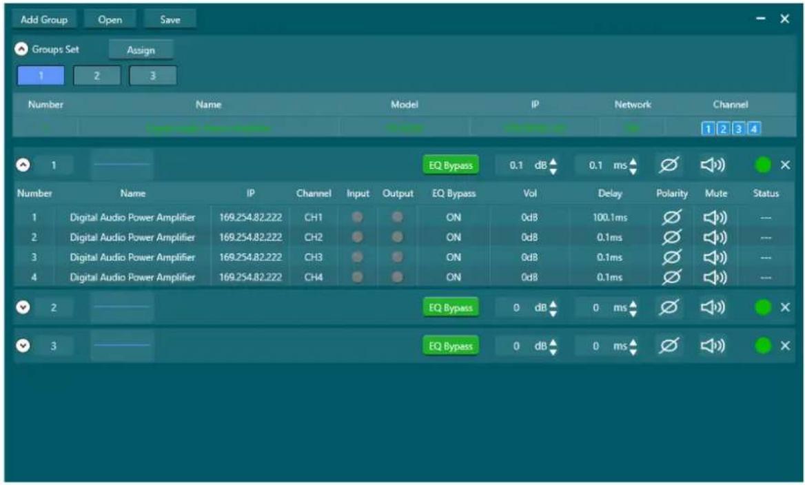
In the Groups menu, you can control input channels across multiple channels and amplifiers.
Click the Groups button on the Device List (see 6.7.1. Device List) to open the Groups menu.
The Groups menu has the following options:
- Top ribbon: Click the Add Group button to create a new group, click the Open button to open a• group configuration from your PC or click Save button to save your group configuration to your PC
- Groups Set: Assign amplifier channels to a specific group (see 6.7.2.1. Groups Set)
- Group settings: Change the amplifier settings for all channels in the group
6.7.2.1. Groups Set

To assign channels to a group, follow the steps below:
01) Click the button for a group in the Groups Set bar.01)
02) Click the buttons for the channels of the available amplifiers, underneath the Channel label on the right.02)
03) Click Assign.03)
You can now adjust the settings for all the channels in a group (see 6.7.2.2. Group Settings).
6.7.2.2. Group Settings

You can adjust the following settings for every group:
- Group name: Click the group name label to change the name of the group
- Input EQ: Click the blue Input EQ line to assign an 8-band parametric equalizer to the group
- EQ Bypass: Turn the EQ Bypass on or off for all channels in the group
- Vol: Change the output level (in dB) for all channels in the group
- Delay: Change the delay (0–100 ms) for all channels in the group
- Polarity: Switch the polarity for all channels in the group
- Mute: Mute and unmute all channels in the group
• Status: View the operating status of each channel in the group
Note: A TA-4.450 that is removed from the network remains in the groups view if it is still assigned to a group. To remove the TA-4.450 from the Groups Set section, delete the group and restart the software.
6.7.3. Main Control Interface
Figure 10
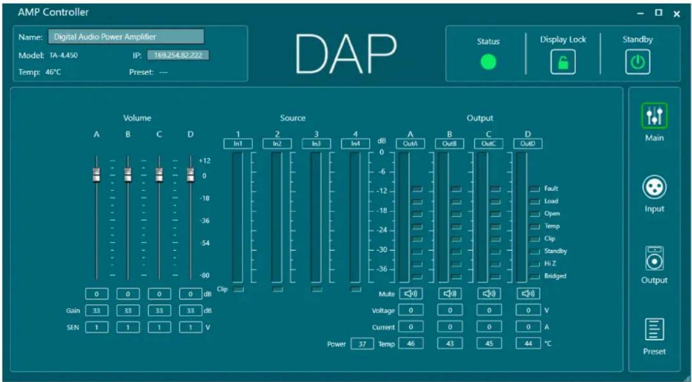
Open the Main Control Interface from the Device list (see 6.7.1. Device List on page 20) or click the Main button on the right of each screen.
The Main Control Interface displays the following items:
• Volume: Set the volume, gain and sensitivity of each output channel (see 6.7.3.1. Volume)
- Source: View the signal level of each input channel and change the label of each input channel
- Output: Check the temperature, output voltage, output current and load status for each channel (see 6.7.3.2. Output). Change the label of each output channel
In the main control interface, you can also change the amplifier name and IP address.
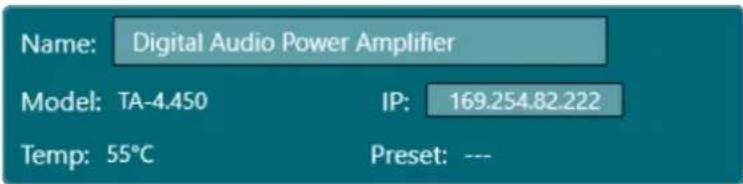
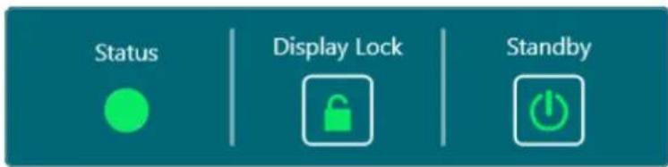
Additionally, you can view the amplifier status (Status), lock the display of the amplifier (Display Lock) and put the amplifier in standby mode (Standby).
6.7.3.1. Volume
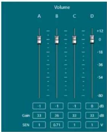
In the Volume section of the main control interface, you can do the following:
- Use the faders or click the values directly below the faders to set the volume of each input channel (-80 to +12 dB)
- Click the gain values to set the gain in dB for each output channel
- Click the SEN values to change the sensitivity value in Volts for each output channel
Figure 11
6.7.3.2. Output
In the Output section of the main control interface, you can do the following:
- Change the label of each output channel
- Check the output level of each output channel
- Check the load status of each output channel
- Mute each output channel
- Check the output voltage of each output channel
- Check the output current of each output channel
- Check the power of the output channels
- Check the temperature of each output channel
An output channel can have the following load statuses: Fault, Load, Open, Temp, Clip, Standby, Hi Z, Bridge.
6.7.4. Input Menu
Figure 12
flowchart
graph TD
    A["Source1 Analog-1 AES3-1 Set In1"] --> B["Delay 0m EQ"]
    C["Source2 Analog-2 AES3-2 Set In2"] --> D["Delay 0m EQ"]
    E["Source3 Analog-3 AES3-1 Set In3"] --> F["Delay 0m EQ"]
    G["Source4 Analog-4 AES3-2 Set In4"] --> H["Delay 0m EQ"]
    B --> I["Source1 Mute 0"]
    D --> J["Mute 0"]
    F --> K["Mute 0"]
    H --> L["Mute 0"]
    I --> M["Link Volume 0dB"]
    J --> N["Link Volume 0dB"]
    K --> O["Link Volume 0dB"]
    L --> P["Link Volume 0dB"]
    M --> Q["A OutA"]
    N --> R["B OutB"]
    O --> S["C OutC"]
    P --> T["D OutD"]
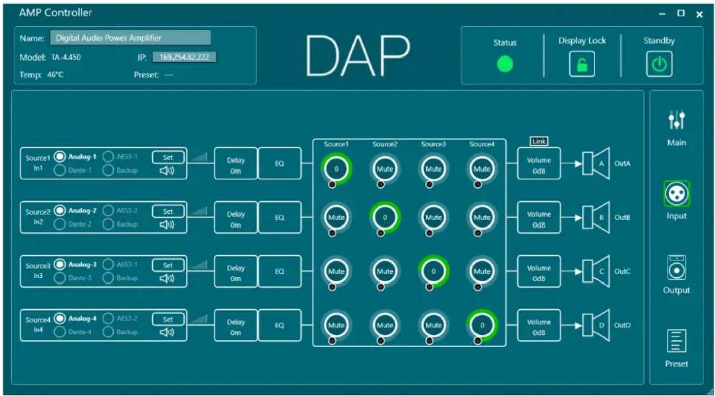
Click the Input button on the right of the Main Control Interface, Output Menu or Preset Menu to open the Input menu. In the Input menu, you can do the following:
- Delay match the sound source and mute the input (see 6.7.4.1. Source Screen)
- Set an input delay of up to 100 ms
- Set an equalizer for each input (see 6.7.4.2. Input Equalizer)
- Set the audio routing and mixing (see 6.7.4.3. Audio Routing and Mixing)
- Set the volume for each channel independently, or combined with the Link button
6.7.4.1. Source Screen
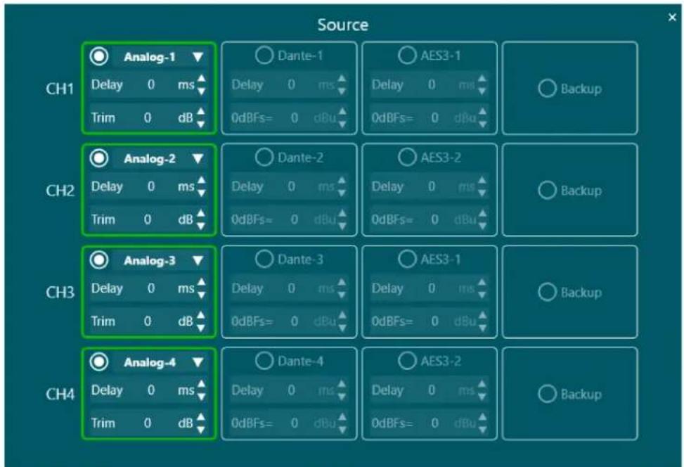
Click the Set button next to a channel on the Input Menu (see 6.7.4. Input Menu) to open the Source screen. In this screen you can do the following for each source channel:
- Set the sound source delay in increments of 0,01 ms (0–10 ms)
- Trim the sound source (-18–+18 dB)
6.7.4.2. Input Equalizer
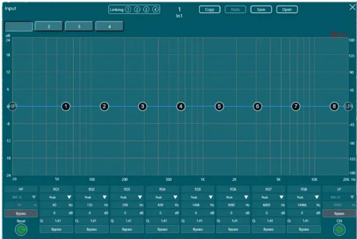
Figure 13
line
| Test Condition | Frequency (Hz) | | :--- | :--- | | HP | 0 | | 1 | 60 | | 2 | 132 | | 3 | 290 | | 4 | 639 | | 5 | 1406 | | 6 | 3092 | | 7 | 6803 | | 8 | 14966 | | LP | 19000 | Bypass ON Reset: Bypass Bypass Bypass Bypass Bypass Bypass Bypass Bypass Bypass Bypass Bypass Bypass Bypass Bypass Bypass Bypass Bypass Bypass Bypass Bypass Bypass Bypass Bypass Bypass Bypass Bypass Bypass Bypass Bypass Bypass Bypass Bypass Bypass Bypass Bypass Bypass Bypass Bypass Bypass Bypass Bypass Bypass Bypass Bypass Bypass Bypass Bypass Bypass Bypass Bypass B bypass Bypass Bypass Bypass Bypass Bypass Bypass Bypass Bypass Bypass Bypass Bypass Bypass Bypass Bypass Bypass Bypass Bypass Bypass Bypass Bypass Bypass Bypass Bypass Bypass Bypass Bypass Bypass Bypass Bypass Bypass Bypass Bypass Bypass Bypass Bypass Bypass Bypass Bypass Bypass Bypass Bypass Bypass Bypass Bypass Bypass Bypass Bypass Bypass Bypass Bayout Output: Linking ① ② ③ ④ In1 Copy Paste Save Open Input: 2 3 4 Color: NoneClick the EQ button next to a channel in the Input Menu (see 6.7.4. Input Menu) to open the Input Equalizer. In this screen you can do the following:
- Adjust the 8-band parametric input equalizer for each channel
- Set a high and low pass filter for each channel
- Phase invert the output polarity with the Phase checkbox at the top right
- Bypass the settings for each band or filter, or bypass all the equalizer settings for the channel
- Link the equalizer settings for one or more channels with the Linking buttons at the top
- Copy and paste the equalizer settings from one channel to another
- Save the equalizer settings to your PC or open existing settings from your PC
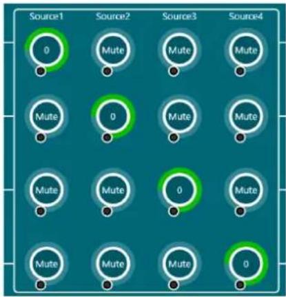
6.7.4.3. Audio Routing and Mixing
In this part of the Input Menu you can connect the source inputs to the desired output channels, mute sources and adjust the volume levels.
Figure 14
6.7.5. Output Menu
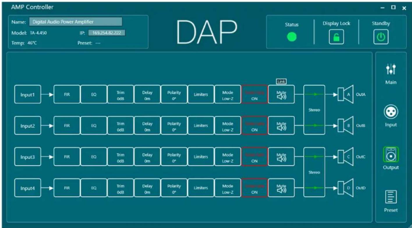
Figure 15
flowchart
graph LR
    A["Input1"] --> B["FIR"]
    C["Input2"] --> D["FIR"]
    E["Input3"] --> F["FIR"]
    G["Input4"] --> H["FIR"]
    B --> I["EQ"]
    D --> J["EQ"]
    F --> K["EQ"]
    H --> L["EQ"]
    I --> M["Trim 0dB"]
    J --> N["Trim 0dB"]
    K --> O["Trim 0dB"]
    L --> P["Trim 0dB"]
    M --> Q["Delay 0m"]
    N --> R["Delay 0m"]
    O --> S["Delay 0m"]
    P --> T["Delay 0m"]
    Q --> U["Polarity 0°"]
    R --> V["Polarity 0°"]
    S --> W["Polarity 0°"]
    T --> X["Polarity 0°"]
    U --> Y["Limiters"]
    V --> Z["Limiters"]
    W --> AA["Limiters"]
    X --> AB["Limiters"]
    Y --> AC["Mode Low-Z"]
    Z --> AD["Mode Low-Z"]
    AA --> AE["Mode Low-Z"]
    AB --> AF["Mode Low-Z"]
    AC --> AG["ON"]
    AD --> AH["ON"]
    AE --> AI["ON"]
    AF --> AJ["ON"]
    AG --> AK["Link"]
    AH --> AL["Link"]
    AI --> AM["Mute"]
    AJ --> AN["Mute"]
    AK --> AO["Stereo"]
    AL --> AP["Stereo"]
    AM --> AQ["A OutA"]
    AN --> AR["B OutB"]
    AO --> AS["C OutC"]
    AP --> AT["D OutD"]
Click the Output button on the right of the Main Control Interface, Input Menu or Preset Menu to open the Output menu. In the Output menu, you can set the following for each channel:
• FIR: Import and export FIR filters
• EQ: Set an output equalizer
- Trim: Trim the volume (-18–+18 dB)
- Delay: Set an output delay up to 20 ms
- Polarity: Set a phase inversion
- Limiters: Set a voltage limiter (see 6.7.5.1. Voltage Limiter)
- Mode: Set the amplifier working mode (Low-Z)
- Noise Gate: Turn the noise gate on or off
- Mute: Mute the channel independently, or combined with the Link button
- Stereo/Bridge: Switch between Stereo and Bridge mode. In Bridge mode, 1 input can be linked to 2 outputs
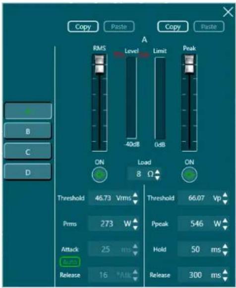
6.7.5.1. Voltage Limiter
In this menu you can set a voltage limiter for each channel. It includes a calculator for the attack and release times.
The Auto option calculates an automatic time constant value based on signal detection.
Figure 16
6.7.6. Preset Menu
Figure 17
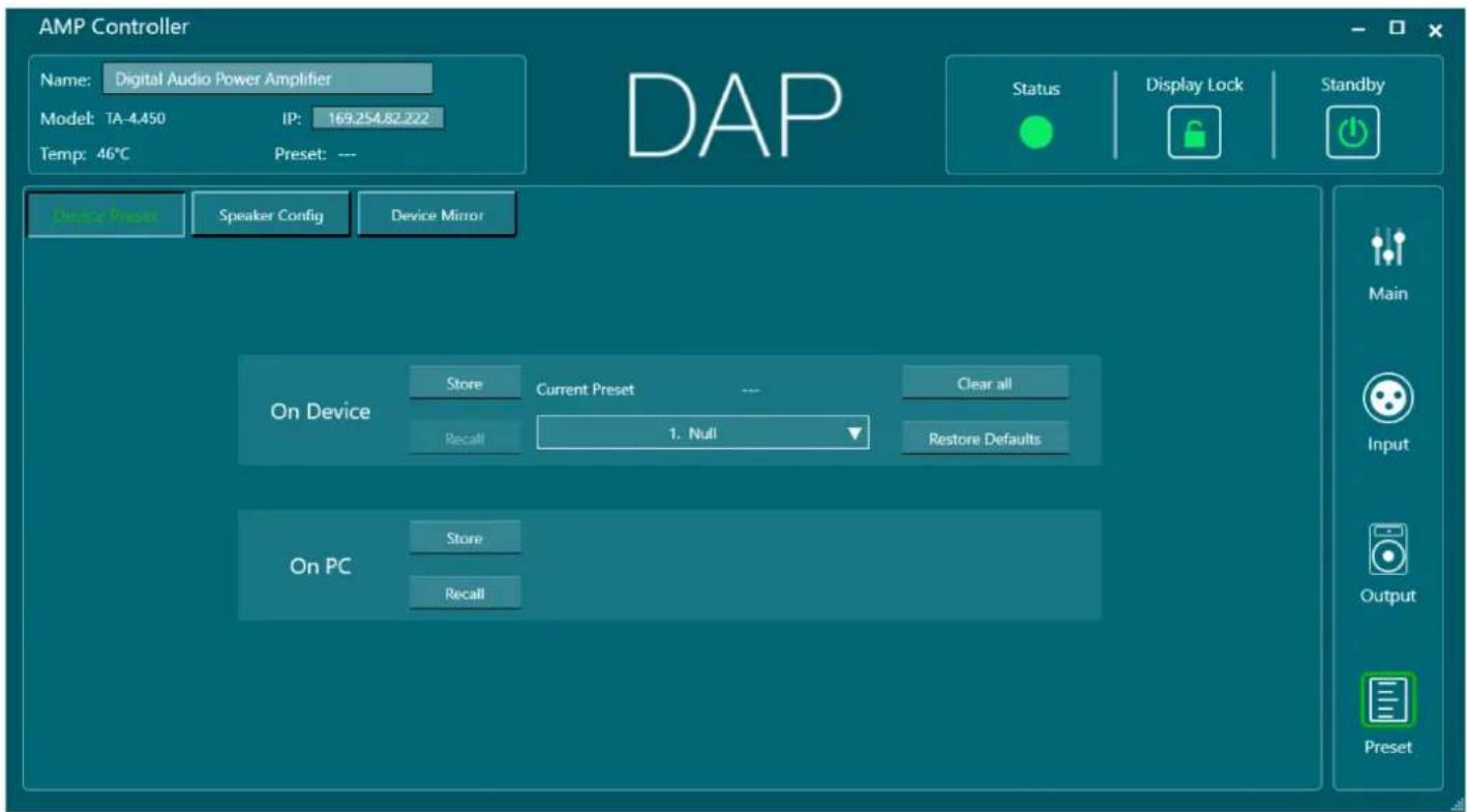
Click the Preset button on the right of the Main Control Interface, Input Menu or Output Menu to open the Preset Menu. In the Preset Menu, you can do the following:
- Store and recall 40 presets
- Store and recall the speaker configuration (see 6.7.6.1. Speaker Configuration Menu)
- Import or export the device image (see 6.7.6.2. Device Mirror Menu)
6.7.6.1. Speaker Configuration Menu
Figure 18
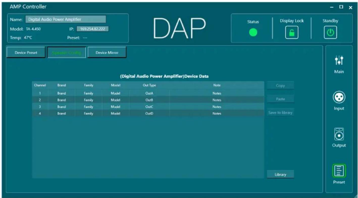
Click the Speaker Config button to open the speaker configuration menu. In this menu you can change the labels for the brand, family, model, output type and add any notes.
- Click any label to change its value.
- Click Save to library to save the speaker configuration to your library.
- Click Library to see, load or delete your saved configurations. You can also import existing configuration files from your PC.
Your saved configurations are stored on your PC. Open the library and click Open folder to see your stored configuration files.
6.7.6.2. Device Mirror Menu
Figure 19
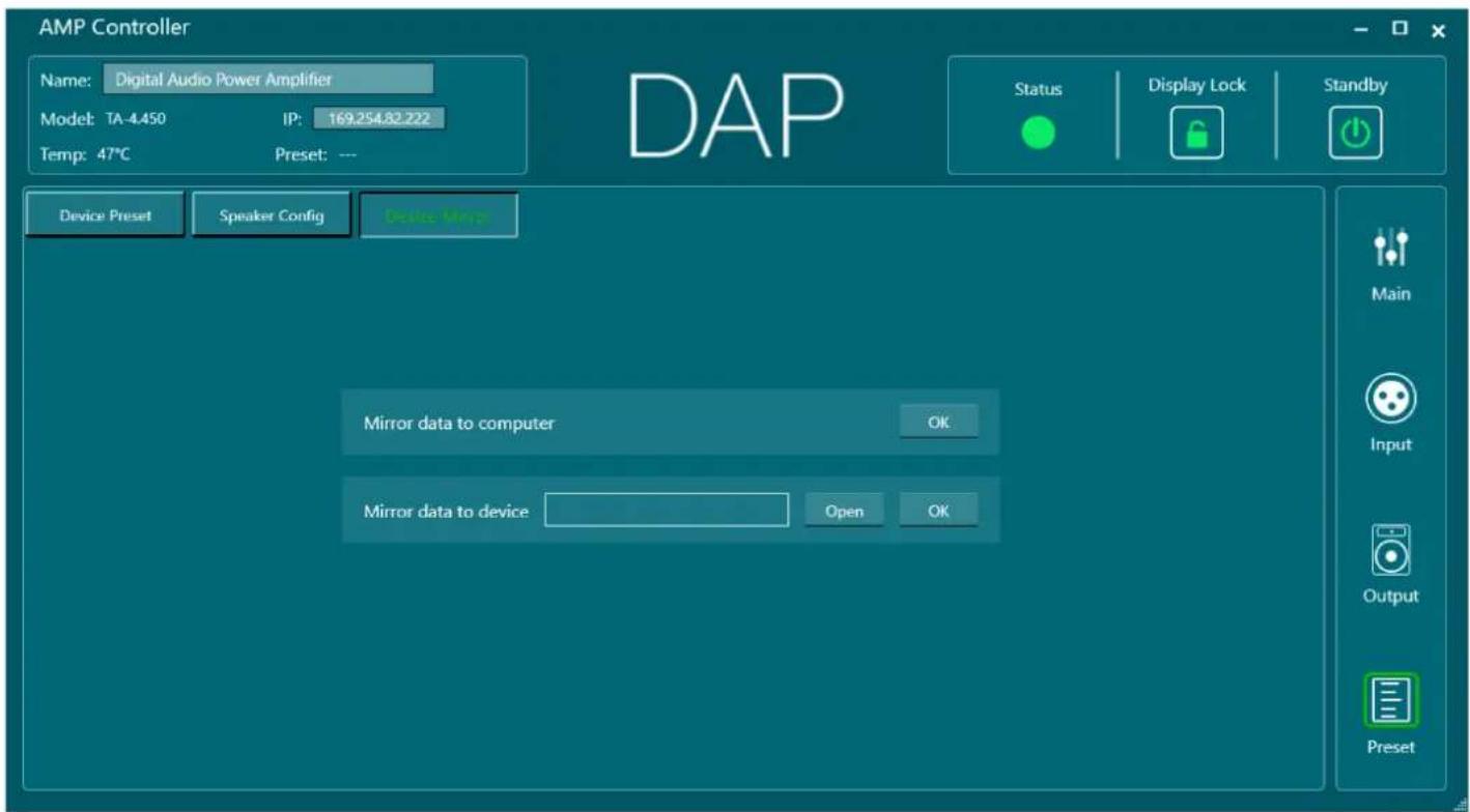
Click the Device Mirror button to open the Device Mirror Menu. In this menu you can create an image of your device and store it to your PC. You can also load existing mirrors from your PC to your device.
7. Troubleshooting
This troubleshooting guide contains solutions to problems which can be carried out by an ordinary person. The device does not contain user-serviceable parts.
Unauthorized modifications to the device will render the warranty void. Such modifications may result in injuries and material damage.
Refer servicing to instructed or skilled persons. Contact your Highlite International dealer in case the solution is not described in the table.
Problem Probable cause(s) Solution
| The device does not function at all | No power to the device | • Make sure that the device is connected to the• power supply and switched on |
| Internal fuse is blown • Contact your Highlite International dealer• | ||
| No sound | The volume is set to minimum | • Increase the volume• |
| The device does not connect to the control software | Incorrect or broken ethernet cable | • Make sure that the device is connected to the• PC with a functioning ethernet cable (minimum Cat. 5) |
8. Maintenance
8.1. Safety Instructions for Maintenance

DANGER
Electric shock caused by dangerous voltage inside
Disconnect power supply before servicing or cleaning.
8.2. Preventive Maintenance

Attention
Before use, examine the device visually for any defects.
Make sure that:
• The housing is not damaged.
- The power cable is not damaged and does not show any material fatigue.
8.2.1. Basic Cleaning Instructions
To clean the device, follow the steps below:
01) Disconnect the device from the electrical power supply.01)
02) Allow the device to cool down for at least 5 minutes.02)
03) Clean the device with a soft, lint-free cloth.03)

Attention
• Do not immerse the device in liquid.
• Do not use alcohol or solvents.
8.2.2. Cleaning the Cooling Vents
The device has two cooling vents on the front. These must be cleaned periodically to prevent the buildup of dust.
To clean the cooling vents, follow the steps below:
01) Disconnect the device from the electrical power supply.01)
02) Allow the device to cool down for at least 1 hour.02)
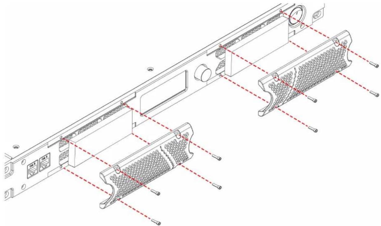
03) Use a hex key to remove the 4 2,5 mm hex screws from the 2 cooling vent covers (04).03)
04) Remove the 2 cooling vent covers (04) and take out the 2 foam pads.04)
05) Clean the foam pads with dry compressed air.05)
06) Clean the vent openings on the device and the 2 cooling vent covers (04) with a soft, lint-free cloth.
07) Place back the foam pads.07)
08) Reinstall the 2 cooling vent covers (04) with the 4 2,5 mm hex screws.08)
Figure 20
8.3. Corrective Maintenance
The device does not contain user-serviceable parts. Do not open the device and do not modify the device.
Refer repairs and servicing to instructed or skilled persons. Contact your Highlite International dealer for more information.
9. Deinstallation, Transportation and Storage
9.1. Instructions for Deinstallation

WARNING
Incorrect deinstallation can cause serious injuries and damage of property.
- Let the device cool down before dismounting.
- Disconnect power supply before deinstallation.
• Always observe the national and site-specific regulations during deinstallation and derigging of the device. - Wear personal protective equipment in compliance with the national and site-specific regulations.
9.2. Instructions for Transportation
- Use the original packaging to transport the device, if possible.
- Always observe the handling instructions printed on the outer carton box, for example: "Handle with care", "This side up", "Fragile".
9.3. Storage
- Clean the device before storing (see 8.2. Preventive Maintenance on page 30).
- Store the device in the original packaging, if possible.
10. Disposal

Correct disposal of this product
Waste Electrical and Electronic Equipment
This symbol on the product, its packaging or documents indicates that the product shall not be treated as household waste. Dispose of this product by handing it to the respective collection point for recycling of electrical and electronic equipment. This is to avoid environmental damage or personal injury due to uncontrolled waste disposal. For more detailed information about recycling of this product contact the local authorities or the authorized dealer.
11. Approval

Check the respective product page on the website of Highlite International (www.highlite.com) for an available declaration of conformity.
- TA-4.450
- Preface
- Table of contents
- Introduction......4
- Safety 6
- Description of the Device....8
- Installation.... 12
- Setup....13
- Operation....16
- Troubleshooting....30
- Maintenance.... 30
- Introduction
- Before Using the Product
- Intended Use
- Text Conventions
- Symbols and Signal Words
- DANGER
- WARNING
- CAUTION
- Electrical hazard
- Symbols on the Information Label
- Safety
- Warnings and Safety Instructions
- Attention Power supply
- Attention General safety
- Attention For professional use only This device must be used only for the purposes it is designed for.
- Attention Before each use, examine the device visually for any defects.
- Attention Do not expose the device to conditions that exceed the rated IP class conditions.
- Requirements for the User
- Description of the Device
- Front View
- Back View
- Product Specifications
- Dimensions
- Optional Accessories and Software
- Installation
- Safety Instructions for Installation
- Attention
- Installation Site Requirements
- Rack Mounting
- Connecting to Power Supply
- Setup
- Setup in Stereo Mode
- Setup in Bridge Mode
- Connecting Multiple Devices
- Note:
- Operation
- Safety Instructions for Operation
- Switching On and Off
- Control Modes
- Start-up
- Menu Overview
- Main Menu Options
- Preset
- Volume
- AMP Mode
- Settings
- Monitor
- Info
- Control Software
- Device List
- Groups Menu
- Groups Set
- Group Settings
- Main Control Interface
- Volume
- Output
- Input Menu
- Source Screen
- Input Equalizer
- Audio Routing and Mixing
- Output Menu
- Voltage Limiter
- Preset Menu
- Speaker Configuration Menu
- Device Mirror Menu
- Troubleshooting
- Maintenance
- Safety Instructions for Maintenance
- Preventive Maintenance
- Basic Cleaning Instructions
- Cleaning the Cooling Vents
- Corrective Maintenance
- Deinstallation, Transportation and Storage
- Instructions for Deinstallation
- Instructions for Transportation
- Storage
- Disposal
- Correct disposal of this product
- Approval
Brand : DAP-Audio
Model : TA-4.450
Category : Receiver