
B550MT - Wall socket BIOSTAR - Free user manual and instructions
Find the device manual for free B550MT BIOSTAR in PDF.


| Type | Wall socket |
| Brand | Biostar |
| Model | B550MT |
| Dimensions (H x W x D) | 86 mm x 86 mm x 40 mm |
| Weight | Approx. 120 g |
| Rated Voltage | 250 V AC |
| Rated Current | 16 A |
| Material | Flame-retardant polycarbonate |
| Output | 1x universal socket |
| Safety Features | Shutter protection, overheat protection |
| Installation | Flush-mounted, requires standard 60 mm back box |
| Color | White |
| Operating Temperature | -10°C to +40°C |
| Ingress Protection | IP20 (indoor use only) |
| Certifications | CE, RoHS |
| Cleaning | Wipe with a dry cloth, do not use water or solvents |
| Spare Parts Available | Replacement front covers, screws |
Frequently Asked Questions - B550MT BIOSTAR
User questions about B550MT BIOSTAR
0 question about this device. Answer the ones you know or ask your own.
Ask a new question about this device
Download the instructions for your Wall socket in PDF format for free! Find your manual B550MT - BIOSTAR and take your electronic device back in hand. On this page are published all the documents necessary for the use of your device. B550MT by BIOSTAR.
USER MANUAL B550MT BIOSTAR
AMD B550 Standard Series
Table of Contents
BIOS Update ....3
UEFI BIOS Setup....7
A.I FAN Control 8
VIVID LED Control 9
- Main Menu ....10
- Advanced Menu....11
- Chipset Menu....24
- Boot Menu....27
- Security Menu....29
- Tweaker Menu ....31
- Save & Exit Menu....34
BIOS Update
The BIOS can be updated using either of the following utilities:
- BIOSTAR BIOS-FLASHER: Using this utility, the BIOS can be updated from a file on a hard disk, a USB drive (a flash drive or a USB hard drive), or a CD-ROM.
- BIOSTAR BIOS Update Utility: It enables automated updating while in the Windows environment. Using this utility, the BIOS can be updated from a file on a hard disk, a USB drive (a flash drive or a USB hard drive), or a CD-ROM, or from the file location on the Web.
BIOSTAR BIO-FLASHER
Note
» This utility only allows storage device with FAT32/16 format and single partition.
» Shutting down or resetting the system while updating the BIOS will lead to system boot failure.
Updating BIOS with BIOSTAR BIO-FLASHER
- Go to the website to download the latest BIOS file for the motherboard.
- Then, copy and save the BIOS file into a USB flash (pen) drive.(Only supported FAT/FAT32 format)
- Insert the USB pen drive that contains the BIOS file to the USB port.
-
Power on or reset the computer and then press
during the POST process. -
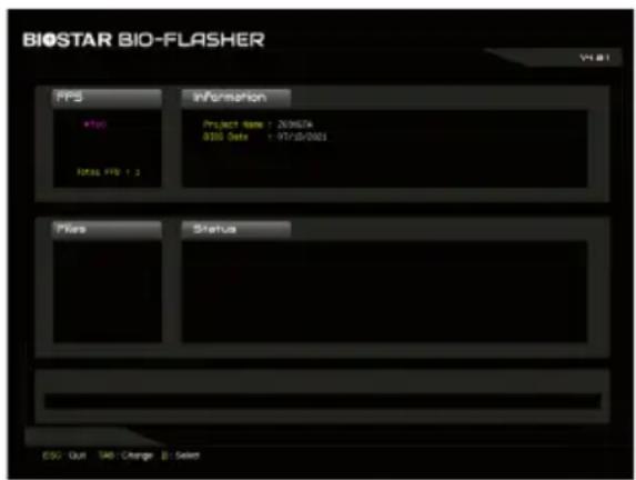
After entering the POST screen, the BIO-FLASHER utility pops out. Choose
to search for the BIOS file. -
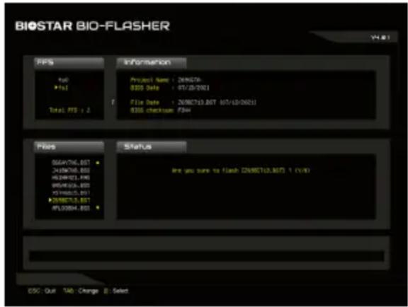
Select the proper BIOS file, and a message asking if you are sure to flash the BIOS file. Click "Yes" to start updating BIOS.
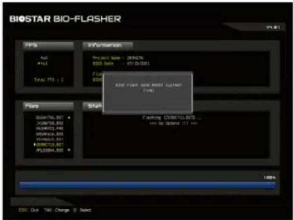
- A dialog pops out after BIOS flash is completed, asking you to restart the system. Press the
key to restart system.
- While the system boots up and the full screen logo shows up, press
key to enter BIOS setup.
After entering the BIOS setup, please go to the
BIOS Update Utility (through the Internet)
- Installing BIOS Update Utility from the DVD Driver.
-
Please make sure the system is connected to the internet before using this function.
-
Launch BIOS Update Utility and click the "Online Update" button on the main screen.
-
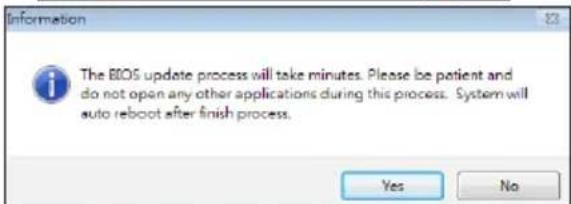
An open dialog will show up to request your agreement to start the BIOS update. Click "Yes" to start the online update procedure.
-
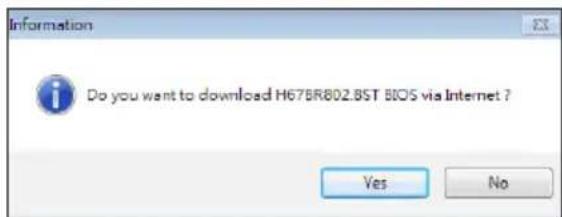
If there is a new BIOS version, the utility will ask you to download it. Click "Yes" to proceed.
-
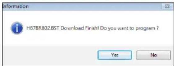
After the download is completed, you will be asked to program (update) the BIOS or not. Click "Yes" to proceed.
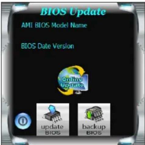
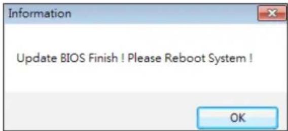
- After the updating process is finished, you will be asked you to reboot the system. Click "OK" to reboot.
- While the system boots up and the full screen logo shows up, press
key to enter BIOS setup.
After entering the BIOS setup, please go to the
BIOS Update Utility (through a BIOS file)
- Installing BIOS Update Utility from the DVD Driver.
-
Download the proper BIOS from http://www.biostar.com.tw/
-
Launch BIOS Update Utility and click the "Update BIOS" button on the main screen.
-
A warning message will show up to request your agreement to start the BIOS update. Click "OK" to start the update procedure.
-
Choose the location for your BIOS file in the system. Please select the proper BIOS file, and then click on "Open". It will take several minutes, please be patient.

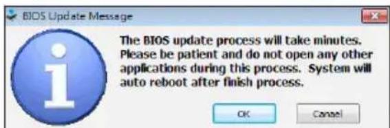
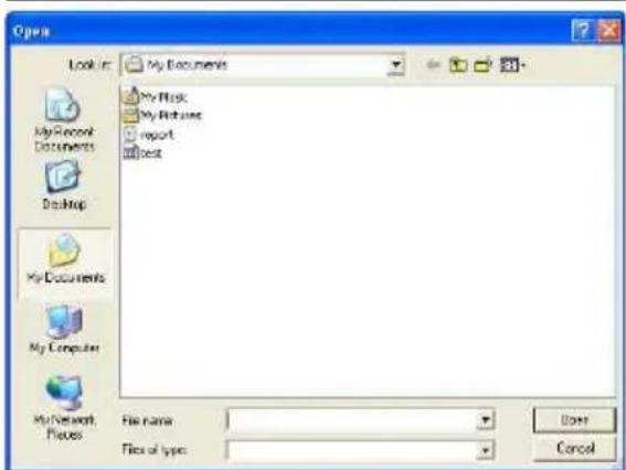
- After the BIOS Update process is finished, click on "OK" to reboot the system.
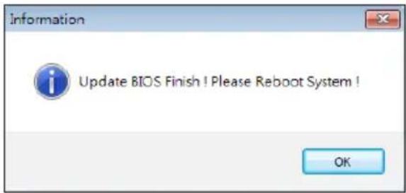
- While the system boots up and the full screen logo shows up, press
key to enter BIOS setup.
After entering the BIOS setup, please go to the
Backup BIOS
Click the Backup BIOS button on the main screen for the backup of BIOS, and select a proper location for your backup BIOS file in the system, and click "Save".
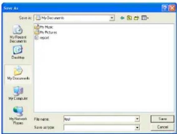
UEFI BIOS Setup
Introduction
The purpose of this manual is to describe the settings in the AMI UEFI BIOS Setup program on this motherboard. The Setup program allows users to modify the basic system configuration and save these settings to NVRAM.
UEFI BIOS determines what a computer can do without accessing programs from a disk. This system controls most of the input and output devices such as keyboard, mouse, serial ports and disk drives. BIOS activates at the first stage of the booting process, loading and executing the operating system. Some additional features, such as virus and password protection or chipset fine-tuning options are also included in UEFI BIOS.
The rest of this manual will to guide you through the options and settings in UEFI BIOS Setup.
Plug and Play Support
This AMI UEFI BIOS supports the Plug and Play Version 1.0A specification.
EPA Green PC Support
This AMI UEFI BIOS supports Version 1.03 of the EPA Green PC specification.
ACPI Support
AMI ACPI UEFI BIOS support Version 1.0/2.0 of Advanced Configuration and Power interface specification (ACPI). It provides ASL code for power management and device configuration capabilities as defined in the ACPI specification, developed by Microsoft, Intel and Toshiba.
PCI Bus Support
This AMI UEFI BIOS also supports Version 2.3 of the Intel PCI (Peripheral Component Interconnect) local bus specification.
Using Setup
When starting up the computer, press during the Power-On Self-Test (POST) to enter the UEFI BIOS setup utility.
In the UEFI BIOS setup utility, you will see General Help description at the top right corner, and this is providing a brief description of the selected item. Navigation Keys for that particular menu are at the bottom right corner, and you can use these keys to select item and change the settings.
Note
» The default UEFI BIOS settings apply for most conditions to ensure optimum performance of the motherboard. If the system becomes unstable after changing any settings, please load the default settings to ensure system's compatibility and stability. Use Load Setup Default under the Exit Menu.
» For better system performance, the UEFI BIOS firmware is being continuously updated. The UEFI BIOS information described in this manual is for your reference only. The actual UEFI BIOS information and settings on board may be slightly different from this manual.
» The content of this manual is subject to be changed without notice. We will not be responsible for any mistakes found in this user's manual and any system damage that may be caused by wrong-settings.
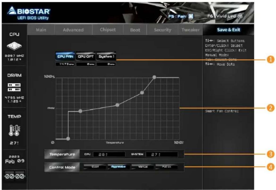
A.I FAN Control
Press
- CPU FAN/ CPU OPT/ System1/ System2/ System3/ MOS FAN: Click button to set the status value of CPU FAN, SYSTEM FAN and MOS FAN.
- PWM/ Temperature Panel: According to the fan PWM value corresponding to CPU and system temperature to adjust the fan speed.
» Allows you to adjust according to your preferences.
- Temperature: Shows the current CPU and system temperature.
-
Control Mode: Allows you to control mode of the fans.
-
Quiet: Enable Quiet mode.
- Aggressive: Enable Aggressive mode.
-
Manual: Enable Manual mode.
• Full on: Enable Full On mode. -
User Selection: Sets the fan property controls the actual selection operation.
-
Auto: Allows you to adjust the Automatic detection Mode.
- DC: Allows you to adjust the Direct Current (DC) Mode.
- PWM: Allows you to adjust the Pulse Width Modulation (PWM) Mode.
Note
» Menu contents will be different slightly, depending on different motherboard of users' computers.
» Once you are finished making your selections, choose the
VIVID LED Control
Press
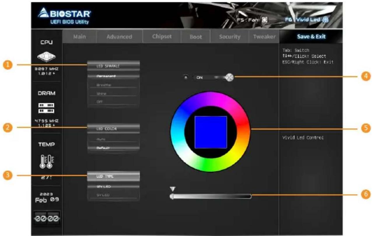
- LED SPARKLE: Allows to you choose sparkle of the LEDs.
• Permanent: LEDs are constantly lit.
- Breath: LEDs gradually flash on and off.
- Shine: LEDs flash at a specific frequency.
- OFF: Allows you to enable or disable VIVID LED of a single item.
-
LED COLOR:
-
Auto: LEDs will Automatically change the Color Palette and LED Brightness.
» If you select Auto mode, the Color Pallette and LED Brightness Bar will disabled. -
Default: All the setting are back to default.
-
LED Type: Select the LED lighting blocks.
• SYSTEM: System LED illuminations. (ARMOR GEAR LED)
• 12V LED: The 12V LED illumination. (12V_LED Device)
- 5V LED: The 5V LED illumination. (5V_LED Device)
-
ON/OFF: To enable or disable VIVID LED function.
-
Color Palette: Allows to you choose specific color of the LEDs.
-
LED Brightness Bar: Allows you to adjust the LED brightness.
Note
» Menu contents will be different slightly, depending on different motherboard of users' computers.
» Once you are finished making your selections, choose the
1. Main Menu
Once you enter AMI UEFI BIOS Setup Utility, the Main Menu will appear on the screen providing an overview of the basic system information.
![BIOSTAR UEFI BIOS Utility CPU 3800 MHz 1.262* DRAM 2133 MHz 1.210* TEMP 29: 2020 Jul 17 00:00 Main Advanced Chipset Boot Security Tweaker Save & Exit BIOS Information Compliance Project Code Model Name BIOS Version Build Date Access Level Memory Information Total Memory System Language English System Date (Fri 07/17/2020) System Time [00:00:09] ++1 Select Screen ↑/Click: Select Item Enter/Db1 Click: Select +/-: Change Opt. F1: General Help F3: Optimized Defaults F10: Save & Exit ESC/Right Click: Exit F11: BIOS Screen Capture F12: BIOS Flash Choose the system default language](/content/2026/05/913030/images/fabc6e98f898dcff48c2f6d61d5b4697f845cdde53b41c6286b73835c4d5fb69.jpg)
BIOS Information
It shows system information including UEFI BIOS version, Project Code, Model Name, Build Date and etc.
Total Memory
Shows system memory size, VGA shard memory will be excluded.
System Language
Choose the system default language.
System Date
Set the system date. Note that the 'Day' automatically changes when you set the date.
System Time
Set the system internal clock.
2. Advanced Menu
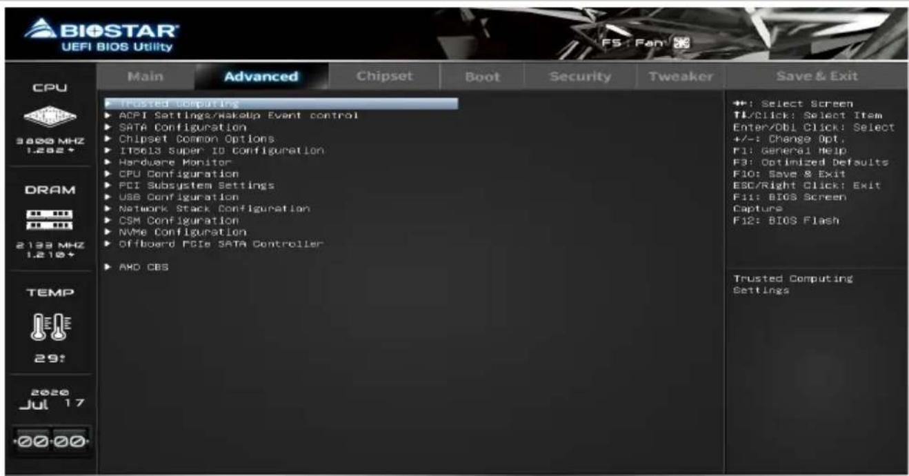
The Advanced Menu allows you to configure the settings of CPU, Super I/O, Power Management, and other system devices.
Note
» Beware of that setting inappropriate values in items of this menu may cause system to malfunction.
Trusted Computing
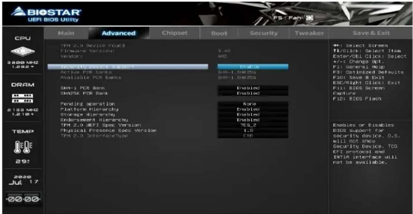
Security Device Support
This item enables or disables BIOS support for security device. O.S. will not show Security Device. TCG EFI protocol and INT1A interface will not be available.
SHA-1 PCR Bank
This item enables or disables SHA-1 PCR Bank.
SHA256 PCR Bank
This item enables or disables SHA256 PCR Bank.
Pending operation
This item Schedule an Operation for the Security Device.
» Your computer will reboot during restart in order to change state of Security Device.
Platform Hierarchy
This item enables or disables Platform Hierarchy.
Storage Hierarchy
This item enables or disables Storage Hierarchy.
Endorsement Hierarchy
This item enables or disables Endorsement Hierarchy.
TPM2.0 UEFI Spec Version
This item select the TCG2 Spec Version support. TCG_1_2: the Compatible mode for Win8/Win10; TCG_2: Support new TCG2 protocol and event format for Win10 or later.
Physical Presence Spec Version
This item select to tell O.S. to support PPI Spec Version 1.2 or 1.3.
» Note some HCK tests might not support 1.3.
ACPI Settings / WakeUp Event control
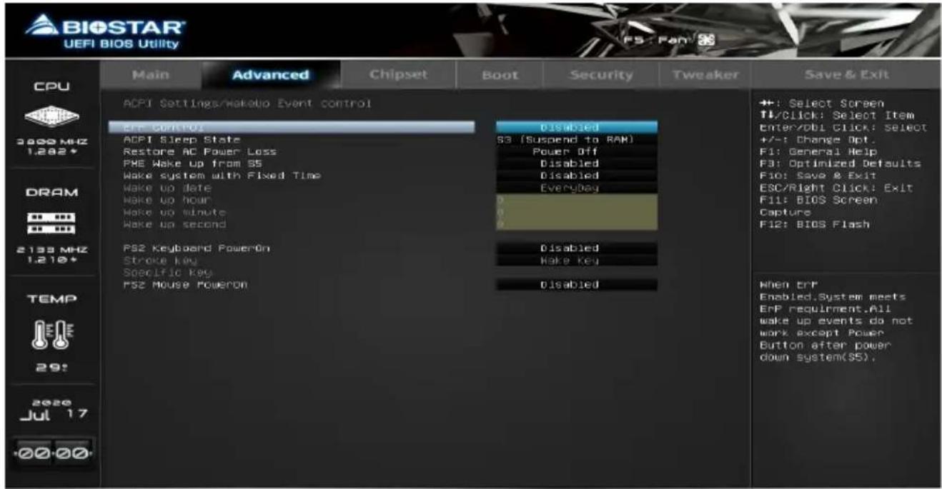
ErP Control
This item enables or disables ErP Control function. When ErP Enabled, system meets ErP requirement. All wake up events do not work except Power Button after power down system(S5).
ACPI Sleep State
This item allows you to select ACPI sleep state the system will enter when the SUSPEND button is pressed.
Restore AC Power Loss
The item specify what state to go to when power is re-applied after a power failure.
PME Wake up from S5
The item enables the system to wake from S5 using PME event.
Wake system with Fixed Time
This item enables or disables the system to wake on by alarm event. When this item is enabled, the system will wake on the hr::min::sec specified.
Wake up date
You can choose which date the system will boot up.
Wake up hour / Wake up minute / Wake up second
You can choose the system boot up time, input hour, minute and second to specify.
PS2 Keyboard PowerOn
This item allows you to control the keyboard power on function.
Stroke Keys
This item will show only when Keyboard PowerOn is set "Stroke Key."
Specific Key
This item will show only when Keyboard PowerOn is set "Specific Key." Press Enter to set Specific key.
PS2 Mouse PowerOn
This item allows you to control the mouse power on function.
SATA Configuration
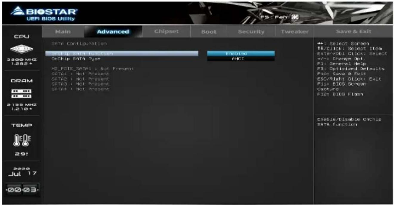
OnChip SATA function
This item enables or disables OnChip SATA function.
OnChip SATA Type
This item select OnChip SATA Type.
Note
» The following items appear only when you set the OnChip SATA Type function to [RAID]
NVMe RAID mode
This item enables or disables NVMe RAID mode.
Chipset Common Options
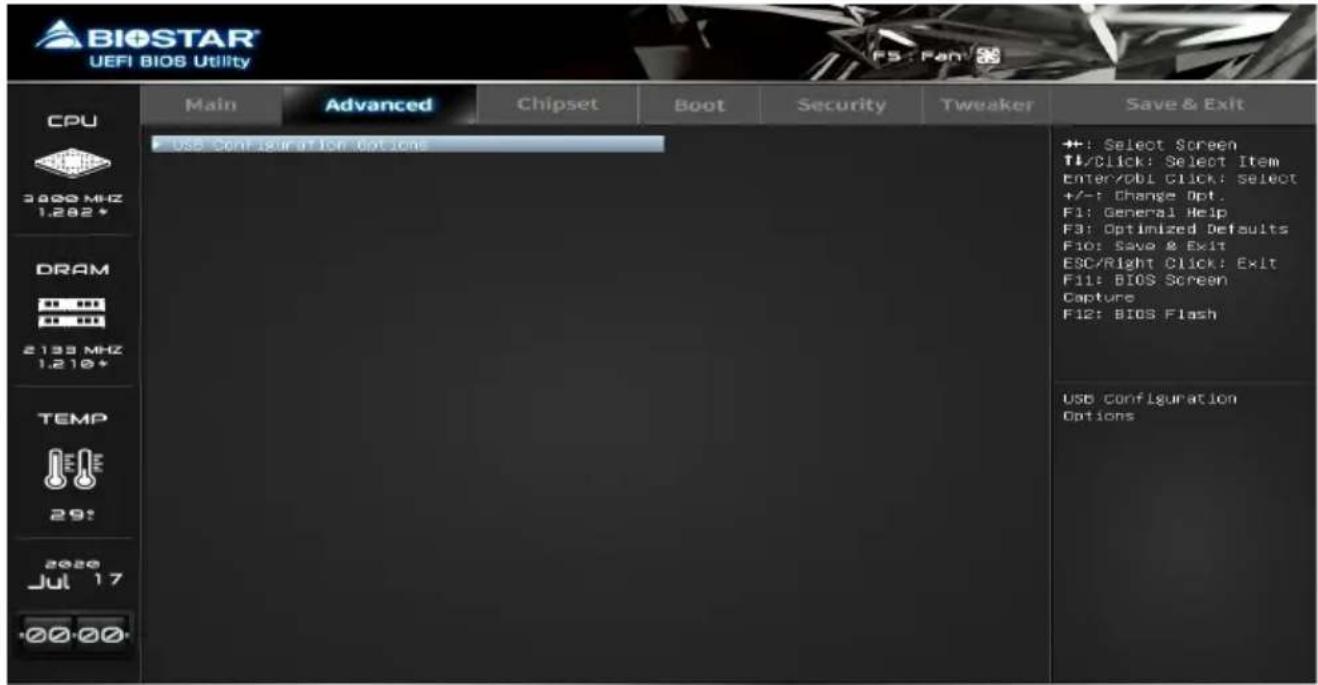
USB Configuration Options
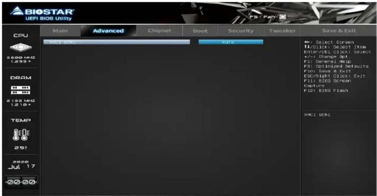
XHCI GEN1
IT8613 Super IO Configuration
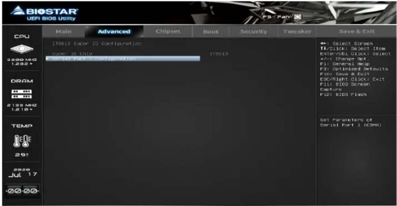
Serial Port Configuration
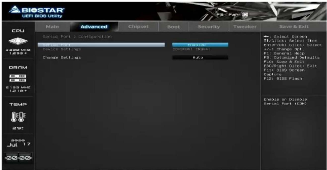
Serial Port
This item enables or disables serial Port.
Change Settings
This item allows you to select an optimal settings for Super IO Device.
H/W Monitor
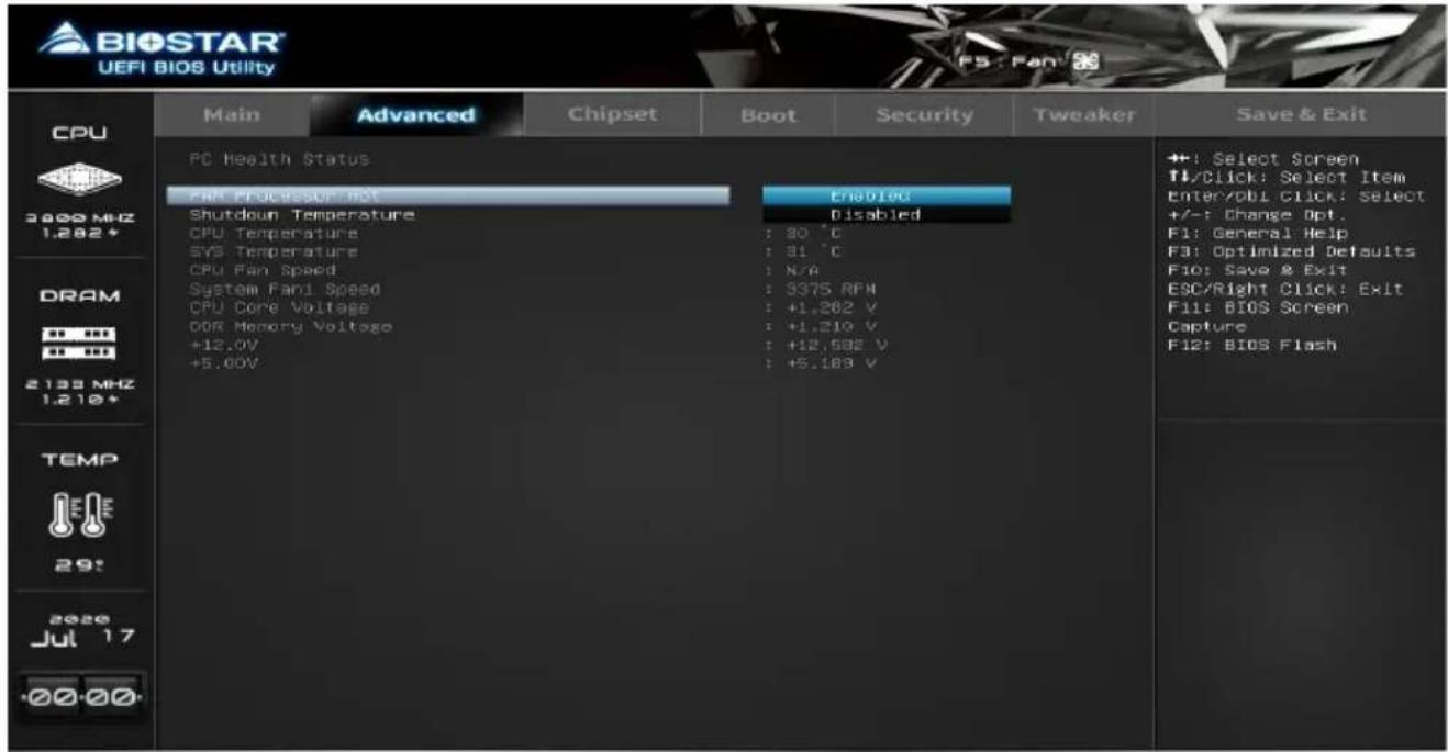
PWM Processor Hot
Shutdown Temperature
This item allows you to set up the CPU shutdown Temperature.
CPU Configuration
This item shows CPU Information.
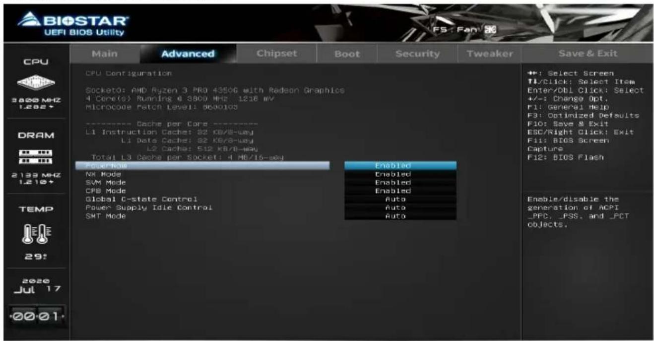
PowerNow
This item enables or disables the generation of ACPI_PPC,_PSS, and _PCT objects.
NX Mode
This item enables or disables No-execute page protection Function.
SVM Mode
This item enables or disables CPU Virtualization.
CPB Mode
This item specifies the method of core performance boost enablement.
Global C-state Control
This item allows you to controls IO based C-state generation and DF C-states.
Power Supply Idle Control
This item enables or disables C6.
SMT Mode
This item enables or disables Simultaneous multithreading. WARNING - S3 is NOT SUPPORTED on systems where SMT is disabled.
PCI Subsystem Settings
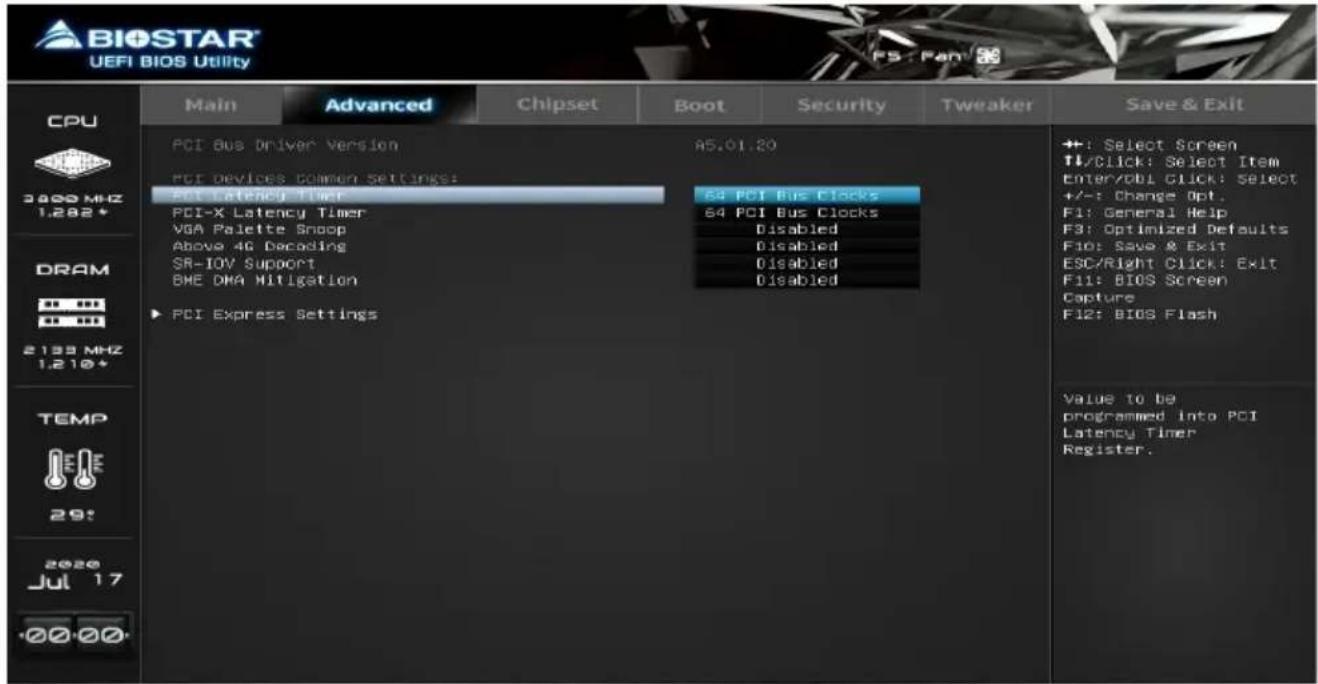
PCI Latency Timer
This item value to be programmed into PCI Latency Timer Register.
PCI-X Latency Timer
This item value to be programmed into PCI Latency Timer Register.
VGA Palette Snoop
This item enables or disables VGA Palette Registers Snooping.
ABove 4G Decoding
This item enables or disables 64bit capable Devices to be Decoded in Above 4G Address Space (Only if System Supports 64bit PCI Decoding).
SR-IOV Support
This item if system has SR-IOV capable PCIe Devices, this option enables or disables Single Root IO Virtualization Support.
BME DMA Mitigation
This item Re-enable Bus Master Attribute disabled during Pci enumeration for PCI Bridges after SMM Locked.
PCI Express Settings
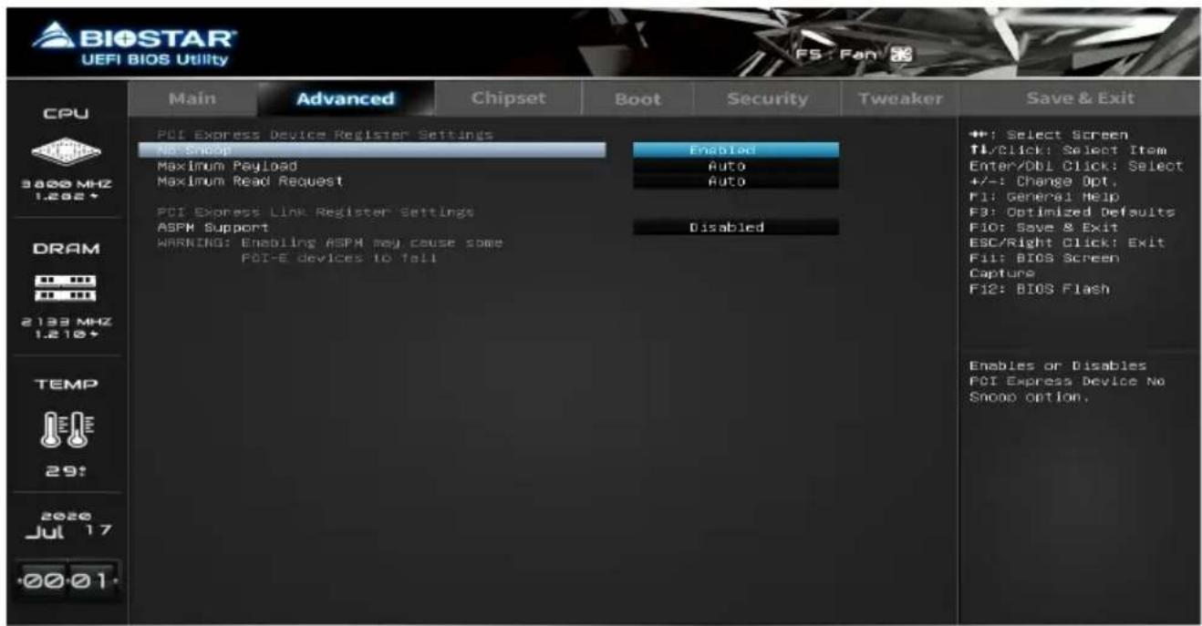
No Snoop
This item enables or disables PCI Express Device No Snoop option.
Maximum Payload
This item set Maximum Payload of PCI Express Device or allow System BIOS to select the value.
Maximum Read Request
This item set Maximum Read Request Size of PCI Express Device or allow system BIOS to select the value.
ASPM Support
This item set the ASPM Level: Force L0s - Force all links to L0s State ; AUTO - BIOS auto configure ; Disable - Disable ASPM.
USB Configuration
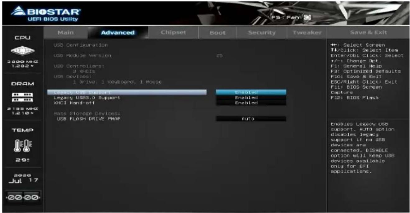
Legacy USB Support
The item allows you to enable Legacy USB support. AUTO option disables legacy support if no USB devices are connected. DISABLE option will keep USB devices available only for EFI applications.
Legacy USB3.0 Support
The item enables or disables legacy USB3.0 support.
XHCI Hand-off
This is a workaround for OSes without XHCI hand-off support. The XHCI ownership change should be claimed by XHCI driver.
USB FLASH DRIVE PMAP
This item Mass storage device emulation type. 'AUTO' enumerates devices according to their media format. Optical drives are emulated as 'CDROM', drives with no media will be emulated according to a drive type.
Network Stack Configuration
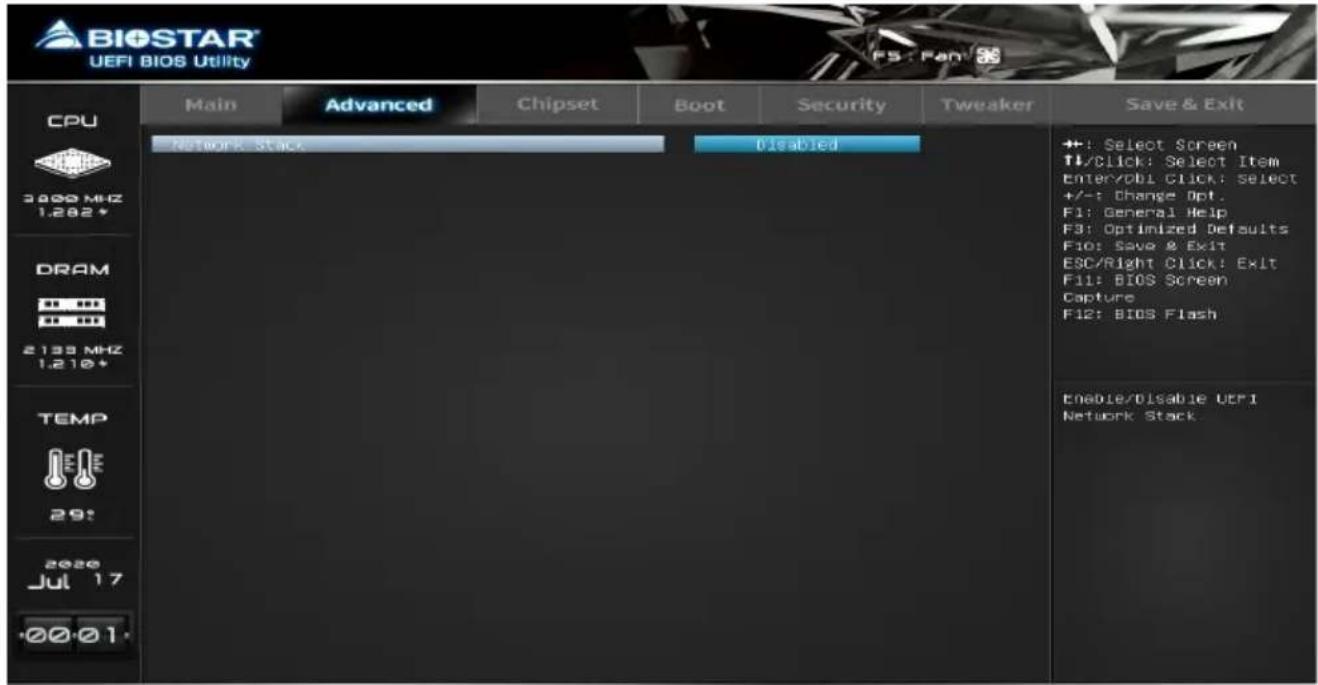
Network Stack
This item enables or disables UEFI network stack
Note
» The following items appear only when you set the Network Stack function to [Enabled]
IPv4 PXE Support
This item enables or disables IPv4 PXE Boot Support. If disabled IPv4 PXE boot option will not be created.
IPv4 HTTP Support
This item enables or disables IPv4 HTTP Boot Support. If disabled IPv4 HTTP boot support will not be created.
IPv6 PXE Support
This item enables or disables IPv6 PXE Boot Support. If disabled IPv6 PXE boot option will not be created.
IPv6 HTTP Support
This item enables or disables IPv6 HTTP Boot Support. If disabled IPv6 HTTP boot support will not be available.
PXE boot wait time
Wait time to press ESC key to abort the PXE boot.
Media detect count
Number of times presence of media will be checked.
CSM Configuration
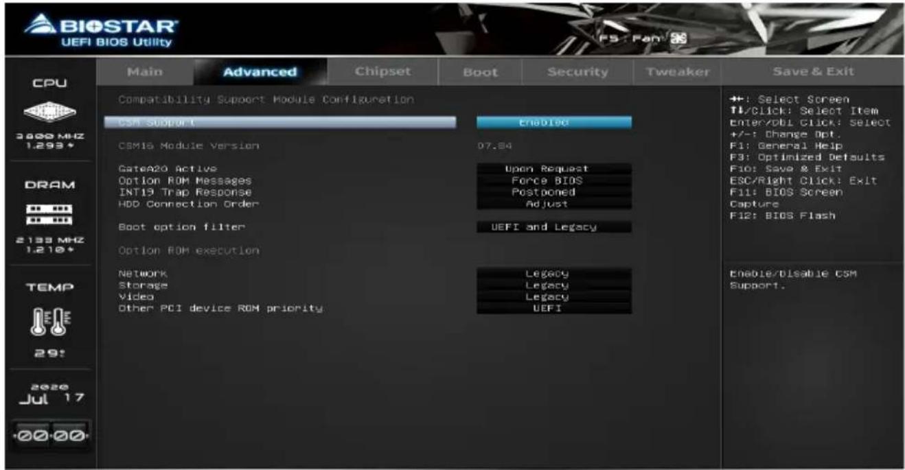
CSM Support
This option enables or disables CSM support.
GateA20 Active
Upon Request – GA20 can be disabled using BIOS services. Always – do not allow disabling GA20; this option is useful when any RT code is executed above 1MB.
Option ROM Messages
This item set display mode for Option ROM.
INT19 Trap Response
This item BIOS reaction on INT19 trapping by Option ROM: IMMEDIATE - execute the trap right away; POSTPONED - execute the trap during legacy boot.
HDD Connection Order
This some OS require HDD handles to be adjusted, i.e. OS is installed on drive 80h.
Boot option filter
This option controls Legacy/UEFI ROMs priority.
Network
This option controls the execution of UEFI and Legacy Network OpROM
Storage
This option controls the execution of UEFI and Legacy Storage OpROM
Video
This option controls the execution of UEFI and Legacy Video OpROM
Other PCI device ROM priority
This item for PCI devices other than Network, Mass storage or Video defines which OpROM to launch.
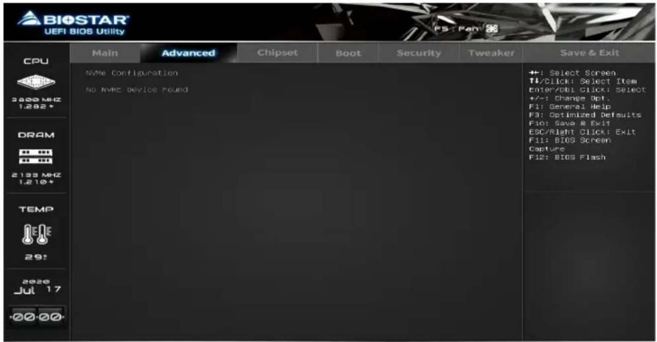
NVMe Configuration
The item shows NVMe controller and driver information.
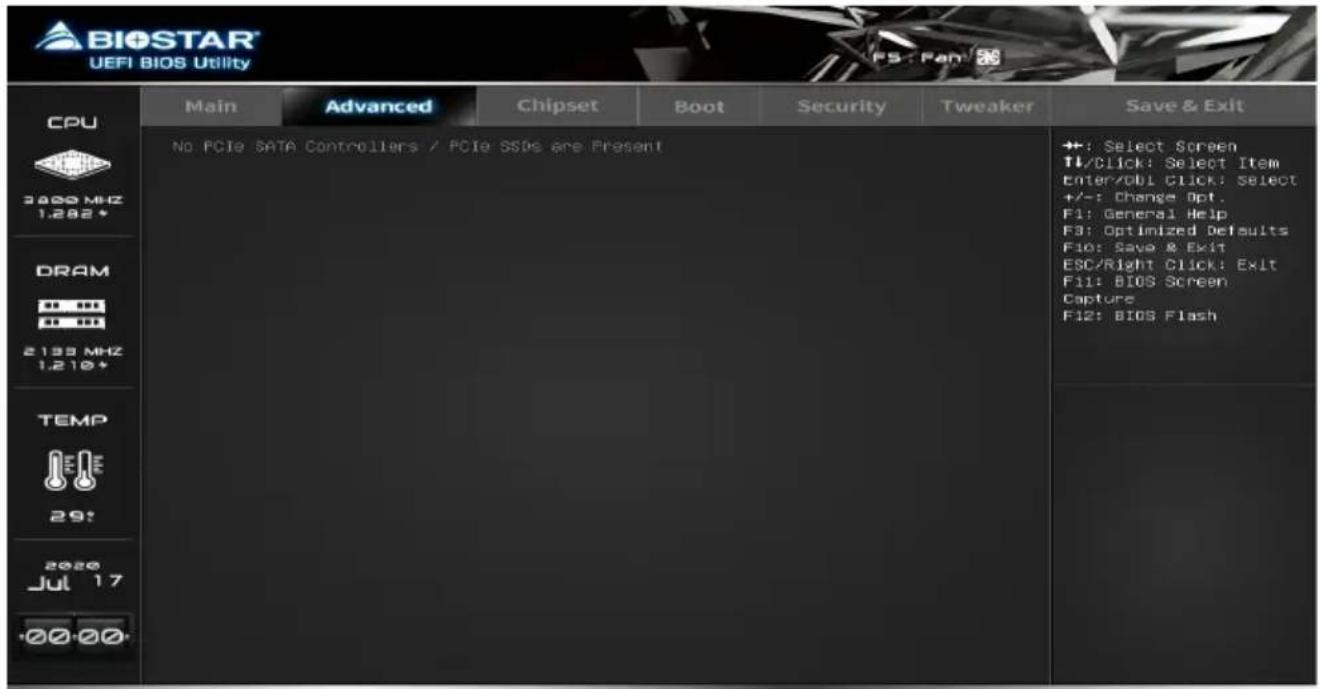
Offboard PCIe SATA Controller
3. Chipset Menu
This section describes configuring the PCI bus system. PCI, or Personal Computer Interconnect, is a system which allows I/O devices to operate at speeds nearing the speed of the CPU itself uses when communicating with its own special components.
Note
» Beware of that setting inappropriate values in items of this menu may cause system to malfunction.
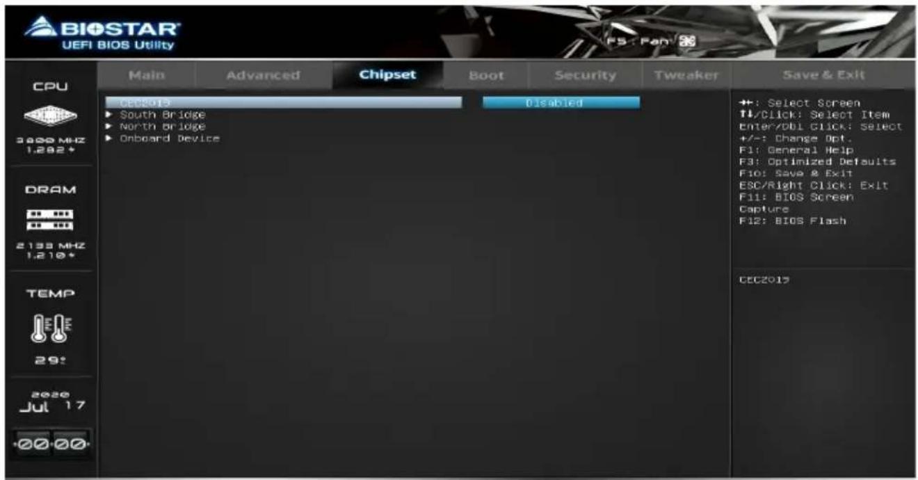
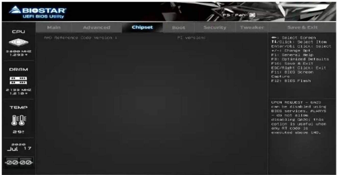
South Bridge
North Bridge
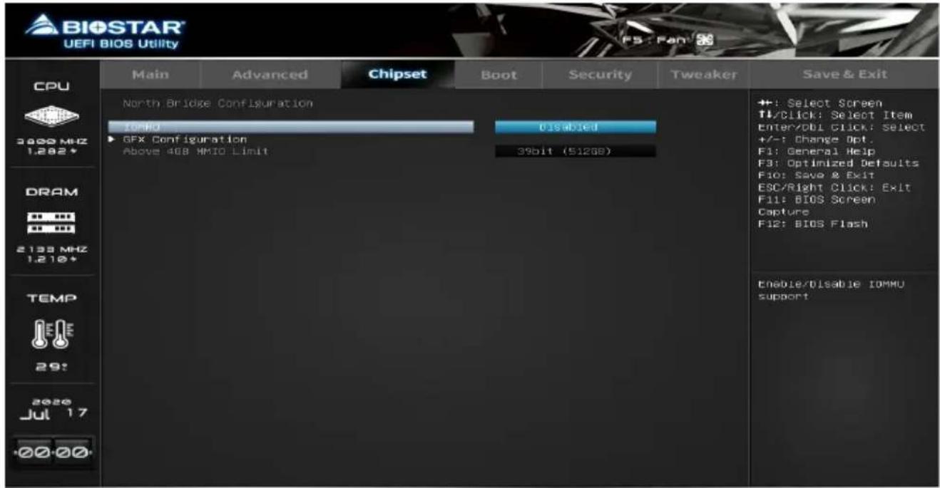
IOMMU
This item enables or disables IOMMU support.
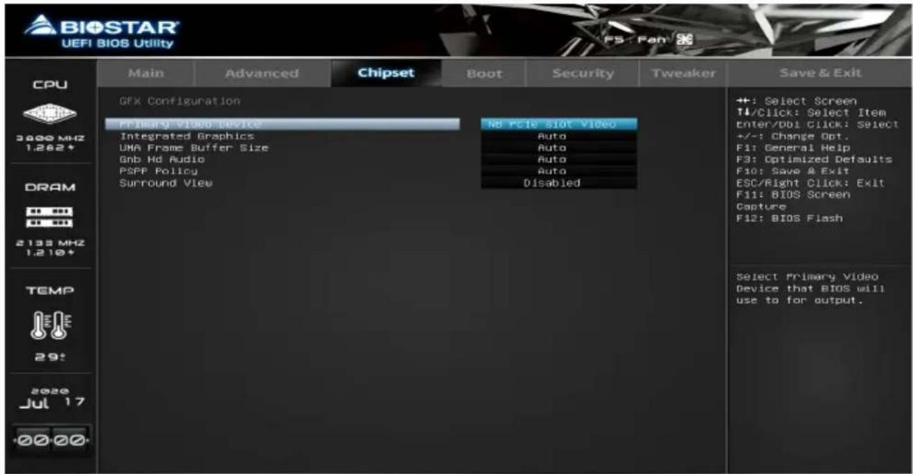
GFX Configuration
Note
» The menu contents of the GFX Configuration will be slightly different depending on the CPU of the motherboard configuration.
Primary Video Device
This item select Primary Video Device that BIOS will use to for output.
Integrated Graphics
This item allows you to controller the Integrated Graphics function.
UMA Frame Buffer Size
This item allows you to set UMA FB Size.
Gnb Hd Audio
This item enable or disable Gnb Hd Audio Support.
PSPP Policy
This item allows you to set PCIe speed power policy.
Surround View
This item support multi-display function.
Onboard Device
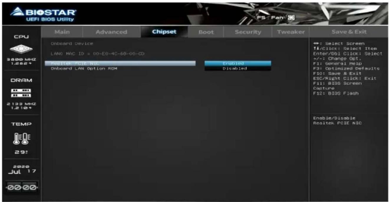
Realtek PCIE NIC
This item enables or disables Intel PCIE NIC.
Onboard LAN Option ROM
This item enables or disables Onboard LAN Option ROM.
4. Boot Menu
This menu allows you to setup the system boot options.
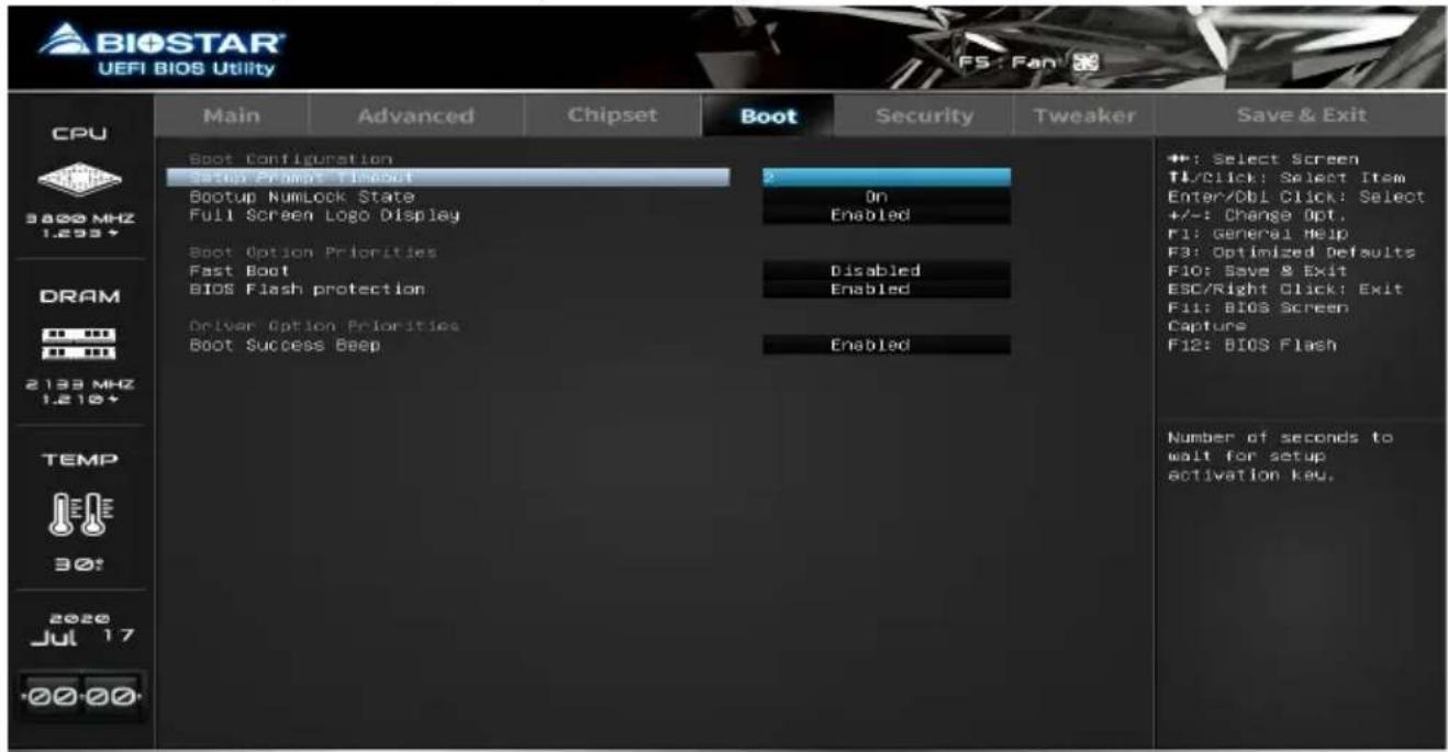
Setup Prompt Timeout
This item sets number of seconds to wait for setup activation key.
Bootup NumLock State
This item selects the keyboard NumLock state.
Full Screen Logo Display
This item enable or disable Full Screen Logo Show function.
Boot Option #1 / #2
This item allows you to sets the system boot order.
Fast Boot
This item enable or disable boot with initialization of a minimal set of devices required to launch active boot option. Has no effect for BBS boot options.
Note
» The following items appear only when you set the Fast Boot function to [Enabled]
SATA Support
If Last Boot HDD Only, Only last boot HDD device will be available in Post. If All Sata Devices, all SATA devices will be available in OS and Post.
NVMe Support
This item enable or disable NVMe Support. If Disabled, NVMe device will be skipped.
VGA Support
If Auto, only install Legacy OpRom with Legacy OS and logo would NOT be shown during post. EFI driver will still be installed with EFI OS.
USB Support
If Disabled, all USB devices will NOT be available until after OS boot. If Partial Initial, USB Mass Storage and specific USB port/device will NOT be available before OS boot. If Enabled, all USB devices will be available in OS and Post.
PS2 Devices Support
If Disabled, PS2 devices will be skipped.
Network Stack Driver Support
If Disabled, Network Stack Drivers will be skipped.
Redirection Support
If Disabled, Redirection function will be disabled.
BIOS Flash protection
While enabled, it can't flash write and flash erase by SMI.
Boot Success Beep
This item BIOS boot post beep message.
5. Security Menu
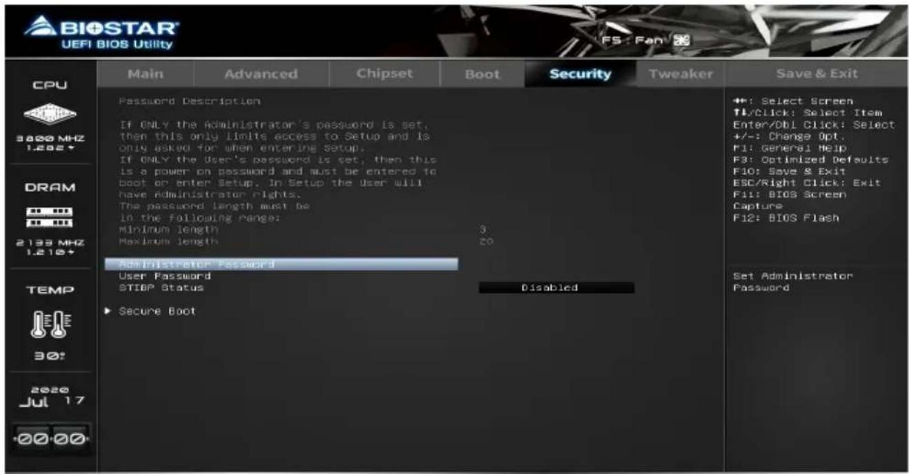
Administrator Password
This item sets Administrator Password.
User Password
This item sets User Password.
STIBP Status
This item single Thread Indirect Branch Predictor(STIBP) is a method to mitigate indirect branch target injection attacks on AMD products.
Secure Boot
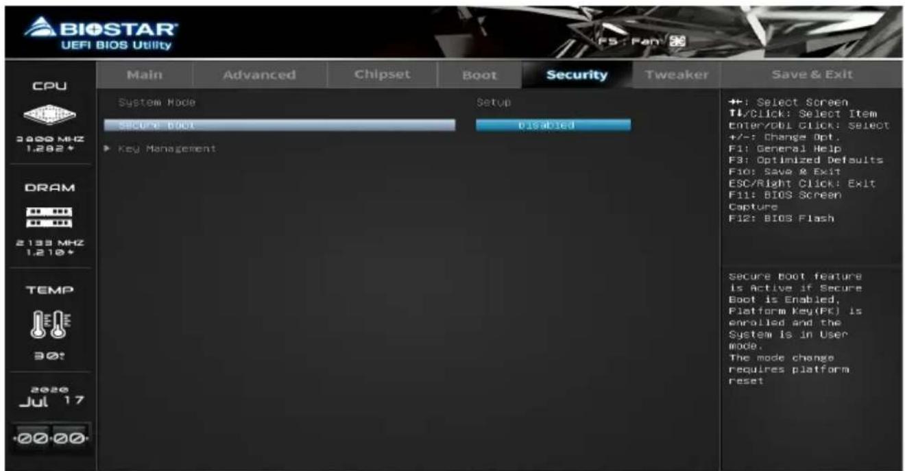
Secure Boot
Secure Boot flow control. Secure Boot can be enabled only when 1. Platform Key (PK) is enrolled and Platform is operating in user mode and 2.CSM function is disabled in Setup.
» Note: The following items appear only when you set the Secure Boot function to [Enabled]
Key Management
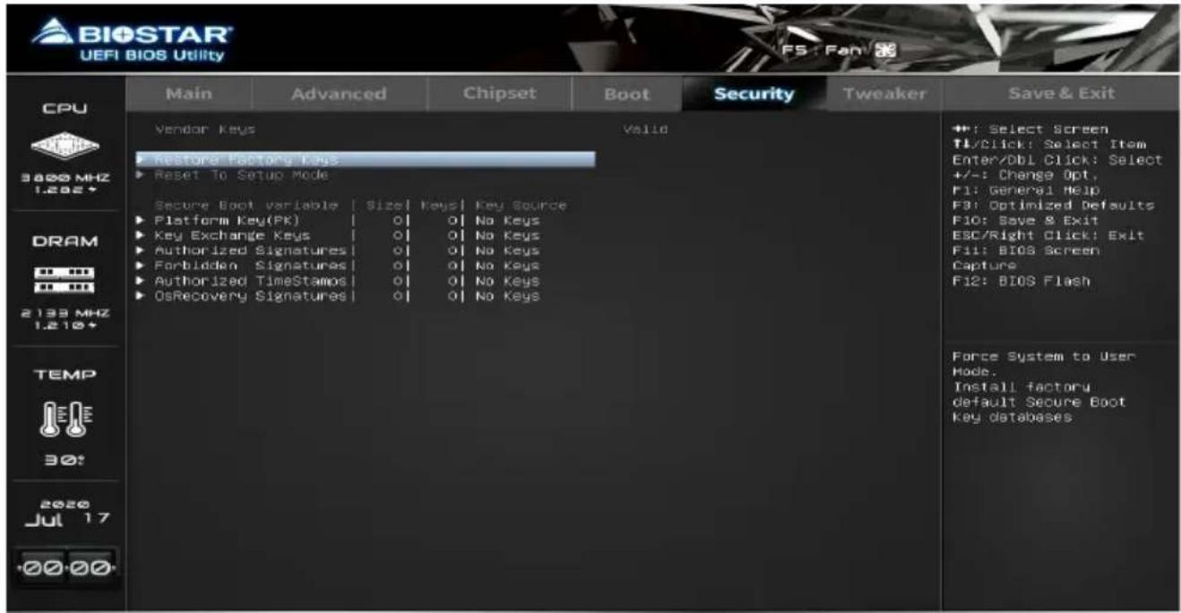
Force System to User Mode. Force system to user.
Reset To Setup Mode
This item delete NVRAM content of all UEFI Secure Boot Key databases.
Platform Key (PK)
Key Exchange Keys
Authorized Signatures
Forbidden Signatures
Authorized Timestamps
OsRecovery Signatures
6. Tweaker Menu
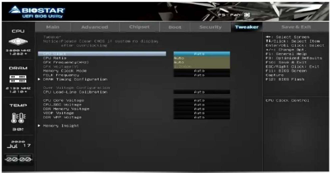
This submenu allows you to change voltage and clock of various devices.
Note
» We suggest you use the default setting. Changing the voltage and clock improperly may damage the device.
» The options and default settings might be different by RAM or CPU models.
» Beware of that setting inappropriate values in items of this menu may cause system to malfunction.
- Values in Red: Danger
- Values in Yellow: Warning
- Values in White: Normal
Note
» The menu contents of the Tweaker will be slightly different depending on the CPU of the motherboard configuration.
CPU Clock
This item allows you to select CPU clock. Range: 100MHz - 300MHz
CPU Ratio
This item allows you to set the CPU Ratio.
GFX Frequency(MHz)
This item allows you to set the GFX Frequency (MHz).
Memory Clock Mode
This item select the DRAM Frequency programming method. If Auto, the DRAM speed will be based on SPDs. If Manual, the DRAM speed specified will be programmed regardless of SPD.
Note
» The menu contents of the Memory clock mode will be slightly different depending on the memory card used by the user.
» The following items appear only when you set the Memory Clock Mode function to [Manual].
Memory Frequency
This item select the memory clock value in MHz.
FCLK Frequency
This item select the memory clock value in MHz.
DRAM Timing Configuration
This item select the DRAM Timing Configuration.
CPU Load-Line Calibration
This item allows you to adjust CPU LLC function.
CPU Core Voltage
This item allows you to control CPU Core Voltage.
Note
» The following items appear only when you set the CPU Core Voltage function to [Override]
CPU Core Adjust Voltage
Note
» The following items appear only when you set the CPU Core Voltage function to [Adaptive]
CPU Core Offset Prefix
CPU Core Offset Voltage
CPU\_SOC Voltage
This item allows you to control CPU_SOC Voltage Control.
Note
» The following items appear only when you set the CPU_SOC Voltage function to [Override]
CPU\_SOC Adjust Voltage
Note
» The following items appear only when you set the CPU_SOC Voltage function to [Adaptive]
CPU_SOC Offset Prefix
CPU_SOC Offset Voltage
DDR Memory Voltage
This item allows you to control DDR Memory Voltage.
VDDP Voltage
This item allows you to control VDDP Voltage.
DDR VPP Voltage
This item allows you to control DDR VPP Voltage.
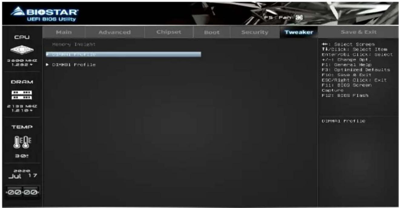
Memory Insight
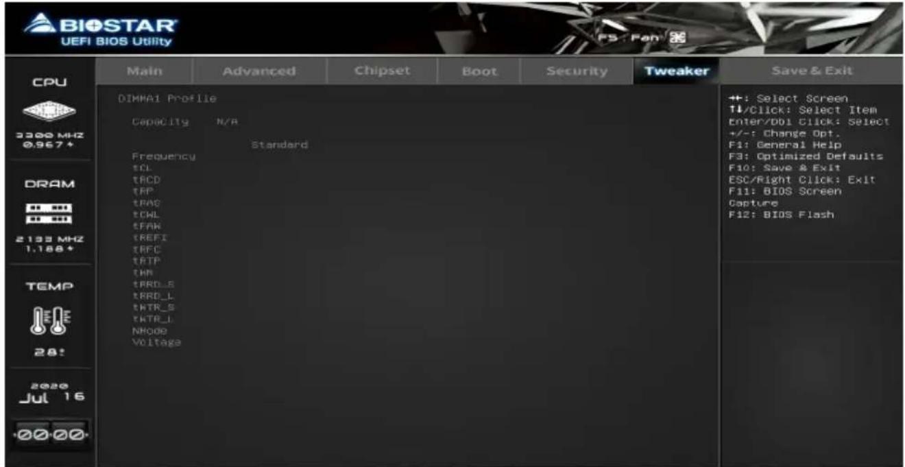
DIMM Profile
These items display memory information.
7. Save & Exit Menu
This menu allows you to load the optimal default settings, and save or discard the changes to the BIOS items.
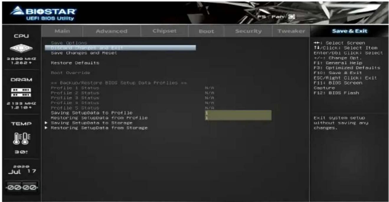
Discard Changes and Exit
Abandon all changes made during the current session and exit setup.
Save Changes and Reset
Reset the system after saving the changes.
Restore Defaults
Restore/Load Default values for all the setup options.
Saving SetupData to Profile
This item Saving SetupData to Profile.
Restoring SetupData from Profile
This item Restoring SetupData from Profile.
Saving SetupData to Storage
This item saves your current BIOS Setup Data to storage devices.
Restoring SetupData from Storage
This item restores your BIOS Setup Data from storage devices.
- Table of Contents
- BIOS Update
- BIOSTAR BIO-FLASHER
- Note
- BIOS Update Utility (through the Internet)
- BIOS Update Utility (through a BIOS file)
- Backup BIOS
- UEFI BIOS Setup
- Introduction
- Plug and Play Support
- EPA Green PC Support
- ACPI Support
- PCI Bus Support
- Using Setup
- A.I FAN Control
- VIVID LED Control
- Main Menu
- BIOS Information
- Total Memory
- System Language
- System Date
- System Time
- Advanced Menu
- Security Device Support
- SHA-1 PCR Bank
- SHA256 PCR Bank
- Pending operation
- Platform Hierarchy
- Storage Hierarchy
- Endorsement Hierarchy
- TPM2.0 UEFI Spec Version
- Physical Presence Spec Version
- ACPI Settings / WakeUp Event control
- ErP Control
- ACPI Sleep State
- Restore AC Power Loss
- PME Wake up from S5
- Wake system with Fixed Time
- Wake up date
- PS2 Keyboard PowerOn
- Stroke Keys
- Specific Key
- PS2 Mouse PowerOn
- SATA Configuration
- OnChip SATA function
- OnChip SATA Type
- NVMe RAID mode
- Serial Port
- Change Settings
- PWM Processor Hot
- Shutdown Temperature
- CPU Configuration
- PowerNow
- NX Mode
- SVM Mode
- CPB Mode
- Global C-state Control
- Power Supply Idle Control
- SMT Mode
- PCI Latency Timer
- PCI-X Latency Timer
- VGA Palette Snoop
- ABove 4G Decoding
- SR-IOV Support
- BME DMA Mitigation
- PCI Express Settings
- No Snoop
- Maximum Payload
- Maximum Read Request
- ASPM Support
- USB Configuration
- Legacy USB Support
- Legacy USB3.0 Support
- XHCI Hand-off
- USB FLASH DRIVE PMAP
- Network Stack Configuration
- Network Stack
- IPv4 PXE Support
- IPv4 HTTP Support
- IPv6 PXE Support
- IPv6 HTTP Support
- PXE boot wait time
- Media detect count
- CSM Configuration
- CSM Support
- GateA20 Active
- Option ROM Messages
- INT19 Trap Response
- HDD Connection Order
- Boot option filter
- Network
- Storage
- Video
- Other PCI device ROM priority
- NVMe Configuration
- Chipset Menu
- South Bridge
- North Bridge
- IOMMU
- GFX Configuration
- Primary Video Device
- Integrated Graphics
- UMA Frame Buffer Size
- Gnb Hd Audio
- PSPP Policy
- Surround View
- Realtek PCIE NIC
- Onboard LAN Option ROM
- Boot Menu
- Setup Prompt Timeout
- Bootup NumLock State
- Full Screen Logo Display
- Boot Option #1 / #2
- Fast Boot
- SATA Support
- NVMe Support
- VGA Support
- USB Support
- PS2 Devices Support
- Network Stack Driver Support
- Redirection Support
- BIOS Flash protection
- Boot Success Beep
- Security Menu
- Administrator Password
- User Password
- STIBP Status
- Secure Boot
- Reset To Setup Mode
- Platform Key (PK)
- Tweaker Menu
- CPU Clock
- CPU Ratio
- GFX Frequency(MHz)
- Memory Clock Mode
- Memory Frequency
- FCLK Frequency
- DRAM Timing Configuration
- CPU Load-Line Calibration
- CPU Core Voltage
- CPU Core Adjust Voltage
- CPU\_SOC Voltage
- CPU\_SOC Adjust Voltage
- DDR Memory Voltage
- VDDP Voltage
- DDR VPP Voltage
- DIMM Profile
- Save & Exit Menu
- Discard Changes and Exit
- Save Changes and Reset
- Restore Defaults
- Saving SetupData to Profile
- Restoring SetupData from Profile
- Saving SetupData to Storage
- Restoring SetupData from Storage
Brand : BIOSTAR
Model : B550MT
Category : Wall socket