DP-HE1201 - Uncategorized IDIS - Free user manual and instructions
Find the device manual for free DP-HE1201 IDIS in PDF.


| Product Type | HDMI & VGA Video Encoder |
| Model | DP-HE1201 |
| Brand | IDIS |
| Dimensions (W x H x D) | 200 mm x 44 mm x 152.3 mm |
| Weight | 800 g (1.72 lb) |
| Power Source | 12 V DC or PoE (IEEE 802.3af Class 3) |
| Power Consumption | 11.4 W |
| Video Inputs | HDMI x1, VGA x1 |
| Video Outputs | HDMI x1 (loop-through), VGA x1 (loop-through) |
| Max Input Resolution (HDMI) | 3840 x 2160 @ 30 Hz |
| Max Input Resolution (VGA) | 1920 x 1080 @ 60 Hz |
| Video Compression | H.265, H.264 (MP), M-JPEG |
| Audio Compression | ADPCM 16K, G.726, G.711 u-Law, G.711 a-Law |
| Multi-Streaming | Quadruple (Primary, Secondary, Tertiary, Quaternary) |
| Max Frame Rate | 30 fps at 3840 x 2160 |
| Ethernet | RJ45 (10/100BASE-T) with PoE |
| Event Detection | Motion, Trip-zone, Audio detection, Tampering, Video loss, System event |
| Remote Control Interface | USB-B (keyboard/mouse emulation) |
| Protocols Supported | ONVIF, RTSP, HTTP, HTTPS, UPnP, FEN |
| Safety Approvals | FCC, CE, KC |
Frequently Asked Questions - DP-HE1201 IDIS
User questions about DP-HE1201 IDIS
0 question about this device. Answer the ones you know or ask your own.
Ask a new question about this device
Download the instructions for your Uncategorized in PDF format for free! Find your manual DP-HE1201 - IDIS and take your electronic device back in hand. On this page are published all the documents necessary for the use of your device. DP-HE1201 by IDIS.
USER MANUAL DP-HE1201 IDIS
HDMI & VGA Video Encoder
User's Manual
DP-HE1201
Before reading this manual
This is a basic operation manual for use of an IDIS HDMI & VGA Video Encoder. Users who are using this product for the first time, as well as users with experience using comparable products, must read this operation manual carefully before use and heed to the warnings and precautions contained herein while using the product. Safety warnings and precautions contained in this operation manual are intended to promote proper use of the product and thereby prevent accidents and property damage and must be followed at all times. Once you have read this operation manual, keep it at an easily accessible location for future reference.

- The manufacturer will not be held responsible for any product damage resulting from the use of unauthorized parts and accessories or from the user's failure to comply with the instructions contained in this manual.
- It is recommended that first-time users of this product and individuals who are not familiar with its use seek technical assistance from their retailer regarding product installation and use.
- If you need to disassemble the product for functionality expansion or repair purposes, you must contact your retailer and seek professional assistance.
- Both retailers and users should be aware that this product has been certified as being electromagnetically compatible for commercial use. If you have sold or purchased this product unintentionally, please replace with a consumer version.
Safety Precautions

CAUTION
RISK OF ELECTRIC SHOCK
DO NOT OPEN

CAUTION: TO REDUCE THE RISK OF ELECTRIC SHOCK,
DO NOT REMOVE COVER (OR BACK).
NO USER-SERVICEABLE PARTS INSIDE.
REFER SERVICING TO QUALIFIED SERVICE PERSONNEL.

The lightning flash with arrowhead symbol, within an equilateral triangle, is intended to alert the user to the presence of uninsulated "dangerous voltage" within the product's enclosure that may be of sufficient magnitude to constitute a risk of electric shock.

The exclamation point within an equilateral triangle is intended to alert the user to the presence of important operating and maintenance (servicing) instructions in the literature accompanying the appliance.
Important Safeguards
1. Read Instructions
All the safety and operating instructions should be read before the appliance is operated.
2. Retain Instructions
The safety and operating instructions should be retained for future reference.
3. Cleaning
Unplug this equipment from the wall outlet before cleaning it. Do not use liquid aerosol cleaners. Use a damp soft cloth for cleaning.
4. Attachments
Never add any attachments and/or equipment without the approval of the manufacturer as such additions may result in the risk of fire, electric shock or other personal injury.
5. Water and/or Moisture
Do not use this equipment near water or in contact with water.
6. Ventilation
Place this equipment only in an upright position. This equipment has an open-frame Switching Mode Power Supply (SMPS), which can cause a fire or electric shock if anything is inserted through the ventilation holes on the side of the equipment.
7. Accessories
Do not place this equipment on an wall or ceiling that is not strong enough to sustain the product. The equipment may fall, causing serious injury to a child or adult, and serious damage to the equipment. Wall or shelf mountings should follow the manufacturer's instructions, and should use a mounting kit approved by the manufacturer.

This equipment and cart combination should be moved with care. Quick stops, excessive force, and uneven surfaces may cause the equipment and cart combination to overturn.
8. Power Sources
This equipment should be operated only from the type of power source indicated on the marking label. If you are not sure of the type of power, please consult your equipment dealer or local power company. You may want to install a UPS (Uninterruptible Power Supply) system for safe operation in order to prevent damage caused by an unexpected power stoppage. Any questions concerning UPS, consult your UPS retailer.
9. Power Cord
Operator or installer must remove power and TNT connections before handling the equipment.
10. Lightning
For added protection for this equipment during a lightning storm, or when it is left unattended and unused for long periods of time, unplug it from the wall outlet and disconnect the antenna or cable system. This will prevent damage to the equipment due to lightning and power-line surges. If thunder or lightning is common where the equipment is installed, use a surge protection device.
11. Overloading
Do not overload wall outlets and extension cords as this can result in the risk of fire or electric shock.
12. Objects and Liquids
Never push objects of any kind through openings of this equipment as they may touch dangerous voltage points or short out parts that could result in a fire or electric shock. Never spill liquid of any kind on the equipment.
13. Servicing
Do not attempt to service this equipment yourself. Refer all servicing to qualified service personnel.
14. Damage requiring Service
Unplug this equipment from the wall outlet and refer servicing to qualified service personnel under the following conditions:
A. When the power-supply cord or the plug has been damaged.
B. If liquid is spilled, or objects have hit the equipment.
C. If the equipment has been exposed to rain or water.
D. If the equipment does not operate normally by following the operating instructions, adjust only those controls that are covered by the operating instructions as an improper adjustment of other controls may result in damage and will often require extensive work by a qualified technician to restore the equipment to its normal operation.
E. If the equipment has been dropped, or the cabinet damaged.
F. When the equipment exhibits a distinct change in performance — this indicates a need for service.
15. Replacement Parts
When replacement parts are required, be sure the service technician has used replacement parts specified by the manufacturer or that have the same characteristics as the original part. Unauthorized substitutions may result in fire, electric shock or other hazards.
16. Safety Check
Upon completion of any service or repairs to this equipment, ask the service technician to perform safety checks to determine that the equipment is in proper operating condition.
17. Field Installation
This installation should be made by a qualified service person and should conform to all local codes.
18. Correct Batteries
Warning: Risk of explosion if battery is replaced by an incorrect type. Dispose of used batteries according to the instructions.
19. Tmra
A manufacturer's maximum recommended ambient temperature (Tmra) for the equipment must be specified so that the customer and installer may determine a suitable maximum operating environment for the equipment.
20. Elevated Operating Ambient Temperature
If installed in a closed or multi-unit rack assembly, the operating ambient temperature of the rack environment may be greater than room ambient. Therefore, consideration should be given to installing the equipment in an environment compatible with the manufacturer's maximum rated ambient temperature (Tmra).
21. Reduced Air Flow
Installation of the equipment in the rack should be such that the amount of airflow required for safe operation of the equipment is not compromised.
22. Mechanical Loading
Mounting of the equipment in the rack should be such that a hazardous condition is not caused by uneven mechanical loading.
23. Circuit Overloading
Consideration should be given to connection of the equipment to supply circuit and the effect that overloading of circuits might have on over current protection and supply wiring. Appropriate consideration of equipment nameplate ratings should be used when addressing this concern.
24. Reliable Earthing (Grounding)
Reliable grounding of rack mounted equipment should be maintained. Particular attention should be given to supply connections other than direct connections to the branch circuit (e.g., use of power strips).
FIn-Text
Symbol Type Description


Caution Important information concerning a specific function.
Note Useful information concerning a specific function.
User's Caution Statement
Caution: Any changes or modifications to the equipment not expressly approved by the party responsible for compliance could void your authority to operate the equipment.
FCC Compliance Statement
THIS EQUIPMENT HAS BEEN TESTED AND FOUND TO COMPLY WITH THE LIMITS FOR A CLASS A DIGITAL DEVICE, PURSUANT TO PART 15 OF THE FCC RULES. THESE LIMITS ARE DESIGNED TO PROVIDE REASONABLE PROTECTION AGAINST HARMFUL INTERFERENCE WHEN THE EQUIPMENT IS OPERATED IN A COMMERCIAL ENVIRONMENT. THIS EQUIPMENT GENERATES, USES, AND CAN RADIATE RADIO FREQUENCY ENERGY AND IF NOT INSTALLED AND USED IN ACCORDANCE WITH THE INSTRUCTION MANUAL, MAY CAUSE HARMFUL INTERFERENCE TO RADIO COMMUNICATIONS. OPERATION OF THIS EQUIPMENT IN A RESIDENTIAL AREA IS LIKELY TO CAUSE HARMFUL INTERFERENCE, IN WHICH CASE USERS WILL BE REQUIRED TO CORRECT THE INTERFERENCE AT THEIR OWN EXPENSE.
WARNING: CHANGES OR MODIFICATIONS NOT EXPRESSLY APPROVED BY THE PARTY RESPONSIBLE FOR COMPLIANCE COULD VOID THE USER'S AUTHORITY TO OPERATE THE EQUIPMENT. THIS CLASS OF DIGITAL APPARATUS MEETS ALL REQUIREMENTS OF THE CANADIAN INTERFERENCE CAUSING EQUIPMENT REGULATIONS.
WEEE (Waste Electrical & Electronic Equipment)
Correct Disposal of This Product
(Applicable in the European Union and other European countries with separate collection systems)

This marking shown on the product or its literature, indicates that it should not be disposed with other household wastes at the end of its working life. To prevent possible harm to the environment or human health from uncontrolled waste disposal, please separate this from other types of wastes and recycle it responsibly to promote the sustainable reuse of material resources.
Household users should contact either the retailer where they purchased this product, or their local government office, for details of where and how they can take this item for environmentally safe recycling.
Business users should contact their supplier and check the terms and conditions of the purchase contract. This product should not be mixed with other commercial wastes for disposal.
Copyright
© 2021 IDIS Co., Ltd.
IDIS Co., Ltd. reserves all rights concerning this operation manual.
Use or duplication of this operation manual in part or whole without the prior consent of IDIS Co., Ltd. is strictly prohibited.
Contents of this operation manual are subject to change without prior notice for reasons such as functionality enhancements.
Registered Trademarks
IDIS is a registered trademark of IDIS Co., Ltd.
Other company and product names are registered trademarks of their respective owners.
The information in this manual is believed to be accurate as of the date of publication even though explanations of some functions may not be included. We are not responsible for any problems resulting from the use thereof. The information contained herein is subject to change without notice. Revisions or new editions to this publication may be issued to incorporate such changes.
The software included in this product contains some Open Sources. You may obtain the corresponding source code which we have to distribute according to the license policy. For more information, refer to System > General page. This product includes software developed by the University of California, Berkeley and its contributors, and software developed by the OpenSSL Project for use in the OpenSSL Toolkit (http://www.openssl.org/). Also, this product includes cryptographic software written by Eric Young (eay@cryptsoft.com).
Covered by one or more claims of the patents listed at patentlist.accessadvance.com.
1
Part 1 - Introduction....8
Product Features 8
Accessories....10
Overview 10
2
Part2 - Remote Setup .... 13
Remote Setup 14
Quick Setup 15
System....15
General 15
Date/Time 16
User/Group 17
Remote Control 17
Network 18
IP Address 18
FEN 19
Port/QoS....20
Bandwidth Control 21
Security 22
IEEE 802.1X 23
Video 23
Camera 24
Streaming 24
Webcasting 25
MAT 26
Privacy Masking....26
Audio 27
Input 27
Event Action 27
Email 28
Remote Callback 28
FTP Upload 29
Event 30
Motion Detection 31
Trip-Zone 32
Audio Detection 33
Tampering 34
Video Loss 34
System Event....35
3 4
Part 3 - IDIS Web .... 3 6
Web Live Mode 38
Part 4 - Appendix....40
Setup Menu Tree (Remote Setup) 40
Specifications....41
Product Features
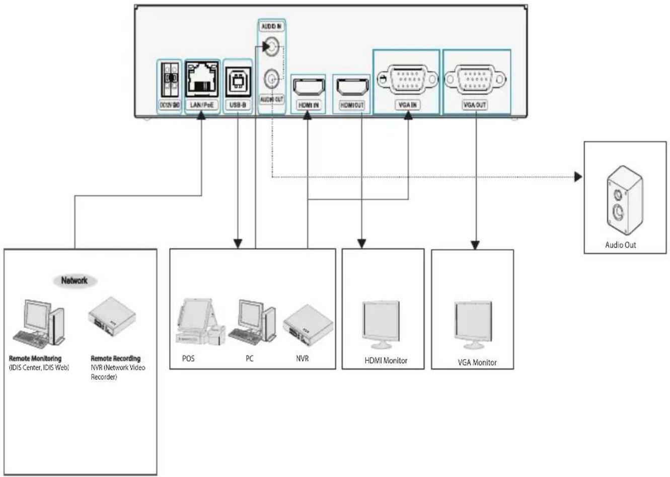
This HDMI&VGA video encoder compresses HDMI and VGA inputs and transmits the video over Ethernet connections. This encoder offers the following features:
- Multi-streaming for monitoring and recording
• H.264 and H.265 compression algorithm - Four levels of video compression and various video compression resolutions
- DirectX protocol supported
• ONVIF protocol supported - Convenient firmware upgrades via network
- Firmware duplication and autorecovery functions to enhance system stability
- Event detection functions: motion, video loss, tampering, tripzone, audio detection, system event, video loss
- 3.5mm Stereo audio input/output (loop-through)
• 1-channel audio network transmission - Easy integration with 3rd party system
• Supports HDMI and VGA input ports - Remote mouse and keyboard control through USB interface
- Configuration of encoder settings and integrated management of multiple encoders on the NVR (Network Video Recorder)
- Configuration of encoder settings and integrated management of multiple encoders on the IDIS Center program (network integration solution)
- Remote control of connection device on the IDIS Center program (video encoder operates as the keyboard or mouse of the USB-connected device).

Video encoding supports one input, either HDMI or VGA. When both are connected, the HDMI input is encoded and transmitted over the network.
Video Encoder Connection Diagram
flowchart
graph TD
    A["Network"] --> B["Remote Monitoring (IDIS Center, IDIS Web)"]
    A --> C["Remote Recording (NVR Network Video Recorder)"]
    A --> D["POS"]
    A --> E["PC"]
    A --> F["NVR"]
    A --> G["HDMI Monitor"]
    A --> H["VGA Monitor"]
    A --> I["Audio Out"]
    I --> J["CCN 90"]
    I --> K["LAN/PoE"]
    I --> L["USB-B"]
    I --> M["AUDIN"]
    I --> N["HDMI IN"]
    I --> O["HDMI OUT"]
    I --> P["VGA IN"]
    I --> Q["VGA OUT"]
    A --> R["Audio Out"]
In addition to the above combinations, various devices can be connected.
Accessories
Upon unpacking the product, check the contents inside to ensure that all the following contents are included.
• HDMI&VGA Video Encoder
- Manual
- USB Cable (A to B Type)
- Rubber feet (4 pack)
Overview
Front Panel
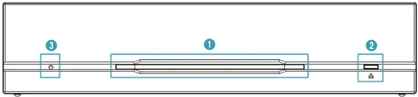
| 1 | Power LED | 2 | Network LED | 3 | Factory Reset Switch |
① Power LED
Displays system operating status
② Network LED
Displays network connection status
LED Status Indications
| LED Status Description | ||
| Power LED | Off No power connection | |
| On System operating | ||
| Network LED | Off No network connection | |
| On or blinking | Network cable is connected | |
③ Factory Reset Switch
Use to return all settings to the original factory settings. Connect the power and poke a straightened paperclip into the factory reset switch hole. Hold the reset switch until the power LED flashes 5 times. When booting is complete, all of the encoder's settings are now at the original settings it had when it left the factory.
- Factory Reset during system booting: All of the encoder's settings are now at the original settings it had when it left the factory.
- Factory Reset during system operating: The other settings except for system log are now at the original settings it had when it left the factory.
- Factory Reset via the IDIS Discovery program (Without network settings): The other settings except for system log and network settings are now at the original settings it had when it left the factory.
- Factory Reset via the IDIS Discovery program (Including network settings): The other settings except for system log are now at the original settings it had when it left the factory.
Rear Panel
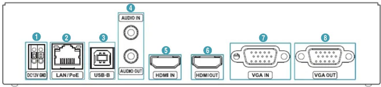
| 1 | DC12V In | 2 | Network + PoE Power In | 3 | USB Port | 4 | Audio In/Out |
| 5 | HDMI In | 6 | HDMI Out | 7 | VGA In | 8 | VGA Out |
① DC12V In
Connect the two wires of the power adapter to these ports. Be careful not to cross the DC12V and ground (GND) wires. Booting will commence once connected to a power supply.
② Network + PoE Power In
Connect a Cat5e cable with an RJ-45 jack. The video encoder is capable of connecting to networks via an Ethernet connector and also receives power through the LAN cable from the NVR and switch hub supporting the PoE function.
③ USB-B
Connect to an USB port to remotely control device such as PC, POS and NVR, etc (keybaord/mouse method).

- When connecting to a device using Windows Operating System, do not remove the cable until the download of the driver software is complete.
④ Audio In/Out
Upper 3.5mm stereo input and lower loop output (only the left side channel transmitts over the network).

When connecting a 3.5mm mono cable to the upper 3.5mm stereo input, the lower loop output may not work normally.
⑤ HDMI Input
Connect an HDMI output such as PC, POS and video recorder, etc. HDMI output signal is transmitted through this video encoder using the network port.
Part 1 - Introduction
⑥ HDMI Output
The input signal is output as an HDMI loop through output.
⑦ VGA Input
Connect an VGA output such as PC, POS and video recorder, etc. VGA output signal is transmitted through this video encoder using the network port.
⑧ VGA Output
The input signal is output as a VGA loop through output.

- The network connector is not designed to be connected directly with cable or wire intended for outdoor use.
- Press down on the button and insert the cable into the opening when you connect the power connectors. Release the button and then pull on the cable slightly to ensure it is held securely in place. To disconnect the cable, press down on the button again and pull the cable out.

- Ground the power port's ground terminal before use.
- Organize the power cable so that it will not cause people to trip over or become damaged from chairs, cabinets, desks, and other objects in the vicinity. Do not run the power cable underneath a rug or carpet.
- Do not connect multiple devices to a single power outlet.
Part2 - Remote Setup
Configure basic HDMI&VGA video encoder settings and all other system settings.

Screen images may vary depending on the model.
USB Remote Control (Keyboard/Mouse)
1 Use a usb cable to connect HDMI&VGA encoder and remote control target.
- If the remote control target uses Microsoft® Windows® operating system, wait for a while until automatic driver software tasks to complete.
2 Set Mouse Properties> Pointer Options in the control panel of remote control device as shown below.
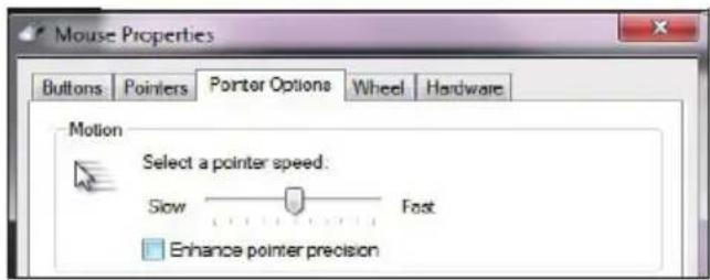
- Select a pointer speed: Right in the middle on the 6th notch.
- Enhance pointer precision : Deselect the setting.
3 Register HDMI&VGA encoder on IDIS Center program to run the remote control function.
4 Right-clicking on the live screen displays the pop-up menu. Select Remote Control to operate the remote control. (Shortcut: R)
| Remote Control | R | |
| Instant Playback | ||
| Playback History | ||
| Play 30 Seconds Before | I |
5 When the remote control system is activated, (Stop remote control) icon ↕ (Initialize the position of pointer) icon are created in the upper right corner of the screen.
- (Initialize the position of pointer): If the mouse pointer of the control target and the one of the live screen do not match, match with this icon.
- (Stop remote control): Select this icon to disable remote control.

If two mouse pointers do not match, refer to the below table.
| Remote Control Target Confirmation of Remote Control Target Remote Settings (DP-HE1201) | ||
| OS: Microsoft®, Windows® | Control Panel Settings• Pointer speed(C) : Center• Enhance Pointer precision(E) : Deselect(If a pointer do not match even after the above settings, refer to Remote Settings (DP-HE1201) on the right.) | System - Remote Control - Select Manual Setup• Display Resolution: Enter the mouse coordinate size of the remote control target manually. |
| OS: Linux Ubuntu® | Disable mouse acceleration and enter xset m 0 0 command. | |
| OS: Mac OS® | Disable mouse acceleration, enter defaults write .GlobalPreferences com.apple.mouse.scaling -1 command and reboot. | |
| IDIS NVR, DVR | Refer to Remote Settings (DP-HE1201) on the right for 3840x2160 resolution. | System - Remote Control - Select Manual Setup• Display Resolution: Enter 1920x1080. |
Remote Setup
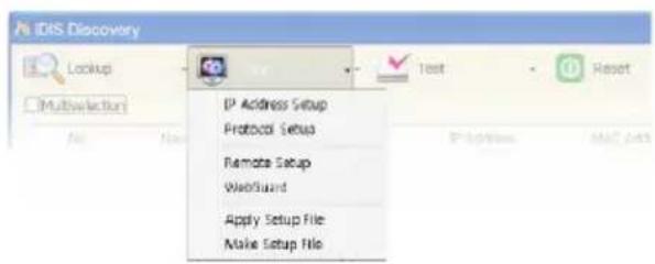
1 Launch the IDIS Discovery program and then from the main screen, select a network encoder whose settings you wish to change.
2 Click on the Setup Icon.
3 Select Remote Setup from the Setup menu to load the Remote Setup screen. Alternatively, you can select encoder from the main screen and then right-click to access the Remote Setup screen.

- System settings can also be changed using a remote program.
- Remote Setup works with the following web browsers when the web browsers support HTML5: Microsoft Internet Explorer version 10 or later, Google Chrome, Mozilla Firefox, or Apple Safari. It may not work properly with Microsoft Internet Explorer version 9.0 or earlier. It is recommended that you update the web browser to the latest version. When you launch Remote Setup on a Microsoft Internet Explorer version 10 or later supporting HTML5 and the Remote Setup screen does not appear, check if the web browser's document mode is set to 9 or higher or Edge. You can check the document mode as follows: Press the F12 key on the keyboard → click the Document mode icon.
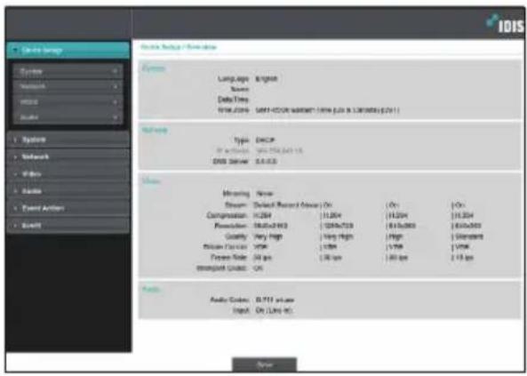
From the Remote Setup screen, select the menu on the left to display the current settings. Select an option under the menu to change the corresponding settings. Once you have changed the settings, click Save to apply the settings.
Quick Setup
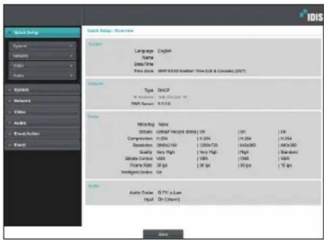
Quick Setup subtab allows you to set up System, Network, Video, Audio, and other basic settings needed for encoder use.
System
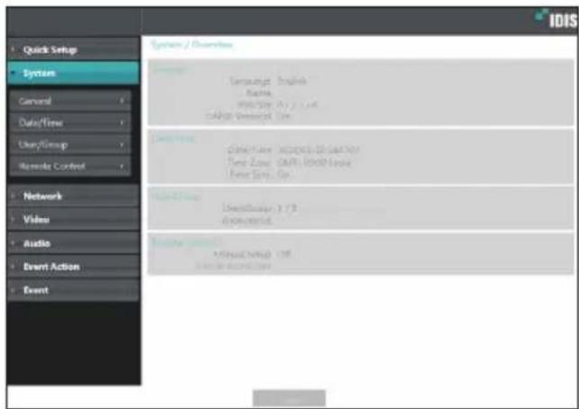
Change the encoder system information, add users/groups, and/or import/export settings.
General
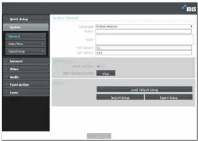
- Language: Select the language you wish to use for remote setup.
- Name: Enter a name for the encoder. (Up to 31 alphanumeric characters, including spaces)
- Note: Enter a description for the encoder.
- HW Version/SW Version: Indicates the encoder's hardware and software versions.
- Miscellaneous
- ONVIF Protocol: Select to enable ONVIF protocol use. However, ONVIF Protocol is available only to users belonging to the standard user groups (Administrator, Operator, and User) and when video compression is set to H.264 or JPEG under Video > Streaming menu. When you have connected to the encoder by using the ONVIF protocol, only the currently enabled streams or events are supported and you cannot change it. There may be some more settings that cannot be changed, too. If you want to change those settings, connect to the encoder by using the IDIS Discovery program.
- ONVIF Event Type
- Normal: A normal way for a camera to deliver events.
- Standard: A way to deliver ONVIF standard events.
- Opensource Licenses: Click View to see the information of opensource licenses.
- Setup
- Load Default Setup: Restores all settings other than Date/Time to their factory defaults. Select Include Network Setup to load default network settings as well. For more information on network setup, refer to the Network on page 18.
- Import Setup: Open a setup file and apply its settings to the encoder. Click on the button and then select a setup file. Select Include Network Setup to apply the file's network setup settings (exc. FEN). For more information on network setup, refer to the Network on page 18.
- Export Setup: Export the current settings as a dat file. Click on the button and then enter a file name.

- When applying the settings of a setup file, do not select the Include Network Setup option if the network settings contained in the selected file is currently being used by a different encoder. Doing so can interfere with establishing a connection with the other encoder.
- If IP Address, Port, and/or SSL settings have been changed, click Save to apply the current settings, and then restart Remote Setup. If you do not restart Remote Setup, the changes afterwards will not be applied.
Date/Time
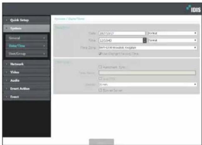
- Date/Time: Change the encoder's date/time settings and display formats and configure the time zone and daylight saving time settings. Click Save to apply the changes right away.
- Time Sync
- Automatic Sync: Select to synchronize the system's time with the time server at a specified interval. Enter the time server's IP address or domain name and then specify the interval. If the time server is FEN-enabled, select the Use FEN option and then enter the time server's name instead of its IP address or domain name.
- Run as Server: Select to run the encoder as a time server. Other devices will then be able to synchronize its time setting with this encoder's time setting.

If you wish to enter a domain name instead of an IP address for the Time Server setting, DNS server must be configured during Network setup. If you wish to enter a server name instead of an IP address or a domain name, the Use FEN option must be enabled during Network setup.
User/Group
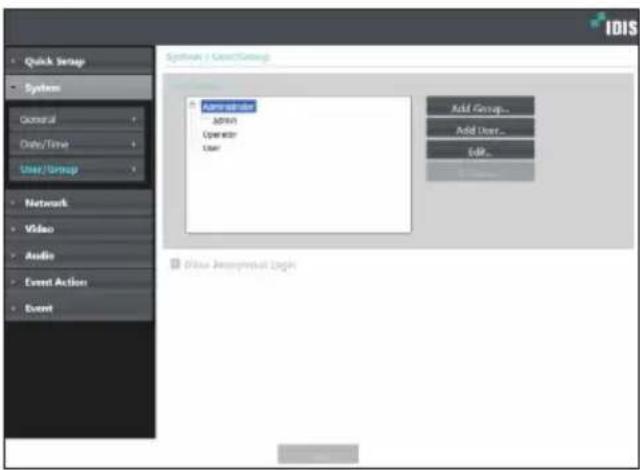
- User/Group: Change remote encoder control permission settings for users and user groups.
- Add Group: Add a new user group. Designate a name for the group and then specify control authorities.
- Add User: Add a new user. Designate a name for the user, select which group to add the user to, and then enter a connection password.
- Edit: Edit group authorities and/or user passwords. Select a group or user and then click on the button.
- Remove: Delete groups or users. Select a group of user you wish to delete and then click on the button.
- Allow Anonymous Login: Select if you are using Webcasting. For more information on webcasting, refer to the Webcasting on page 25.

- User/Group settings can only be configured by users belonging to the Administrator group.
- There is no default password for the Administrator group's admin user.
- Standard groups (Administrator, Operator, and User) cannot be edited or deleted. Authorities assigned here apply identically to ONVIF protocol user groups.
- Group authorities that can be assigned are as follows:
- Upgrade: Upgrade the system.
- Setup: Configure the system's settings.
- Remote Control: Control the connection device on the IDIS Center Program.
Remote Control
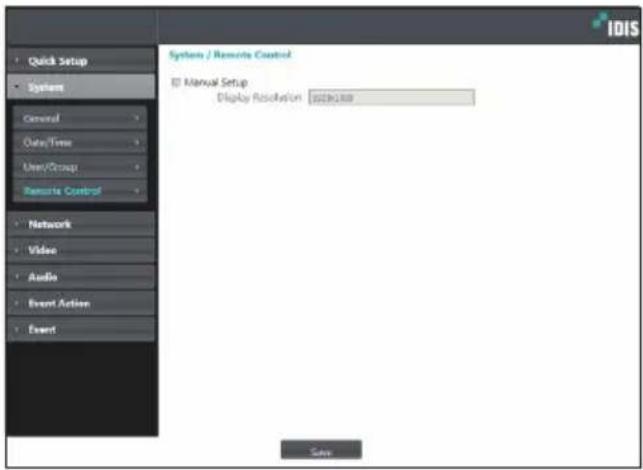
If the mouse pointer of the control target and the one of the live screen do not match, check the remote control target's Control Panel > Mouse Properties and then select Manual Setup as shown above.

For more information on configuring mouse setup, refer to USB Remote Control (Keyboard/Mouse) on page 13.
- Manual Setup : Set the related settings manually.
- Display Resolution : Enter the mouse coordinate size of the remote control target manually.
Network
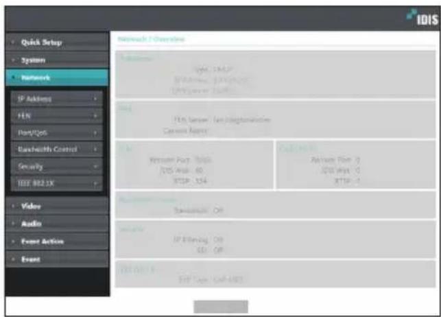
Change the network settings, enable FEN and security features, and control network bandwidth use.
IP Address
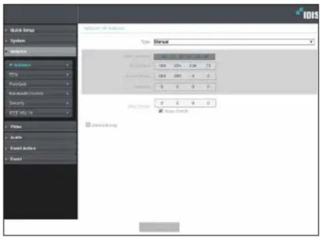
- Type: Select the type of network you are using. If this option has been changed, click Save to apply the current settings, and then restart Remote Setup. If you do not restart Remote Setup, the changes afterwards will not be applied.
- Manual: Select if using a static IP. You will then be able to configure the related settings manually.
- DHCP: Select if connected to the network using DHCP. Click Save to retrieve IP address and other network settings automatically from the DHCP server.
- DNS Server: Enter the DNS server's IP address. By using the DNS server, you will be able to use domain names instead of IP addresses when configuring the FEN, time, or SMTP server. If the encoder is connected to the network via DHCP, select the From DHCP option to retrieve the DNS server's IP address from the DHCP server automatically. The updated address will be displayed upon the subsequent connection.
- Link-local only: Use only the IP addresses of the link-local IP range. (ex:169.254.x.x)

- Contact your network administrator for more information on the encoder's network connection type, the DNS server's IP address, and other related information.
- If using DHCP, the encoder's IP address may change from time to time. We therefore recommend that you use the FEN feature.
FEN
Select Use FEN to enable the FEN feature.
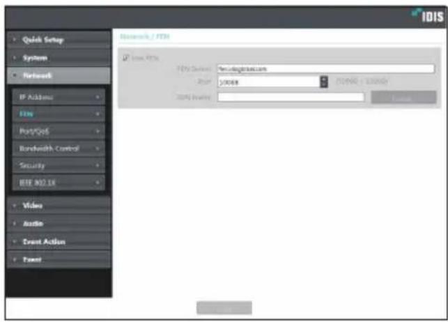
- FEN Server: Enter the FEN Server's IP address or domain name.
- Port: Enter the FEN Server's port number.
- FEN Name: Enter a encoder name you wish to register to the FEN Server. Click OK to check the name's availability.

- Use FEN is a feature that allows you to register a unique name for an encoder that utilizes a dynamic IP address to the FEN Server and connect to the encoder using the registered name instead of an IP address, which can change from time to time. Moreover, you can access the encoder without having to configure NAT (Network Address Translation) device settings even when the encoder uses a NAT device. In order to use this feature, you must first register a FEN name to the FEN Server.
- If network settings have been changed, click Save at the bottom of the setup window to save the changes and then setup the FEN.
- Inquire with your network administrator for the FEN Server's IP address or domain name. If a DNS server has been configured under Network setup, you can enter the FEN Server's domain name instead of its IP address for the FEN Server setting.
- FEN Server's default address is fen.idisglobal.com. DNS server must be configured under network setup to ensure normal operation.
- You will not be able to save FEN settings unless you click on the OK button next to the FEN name field and check the entered name's availability. In addition, you will be prompted with an error message if you do not enter a FEN name or enter a name already registered to the FEN Server. If the FEN name contains the #, \, and/or % symbol, it might not be able to connect to the encoder from the IDIS Web program.

The FEN Server operated by IDIS is a service to its clients and may go offline without notice for server update purposes or due to an unexpected failure.
Port/QoS
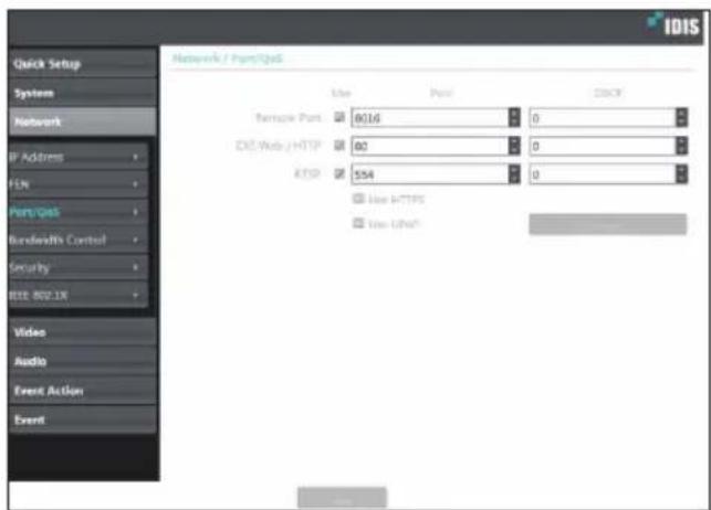
- Use/Port: Enable/disable ports and designate corresponding port numbers. Remote Port and IDIS Web / HTTP ports are enabled by default and cannot be disabled. By enabling IDIS Web and RTSP ports, you will be able to use the IDIS Web program or a media player that supports RTSP (Real-Time Streaming Protocol) service to connect to the encoder. When the HTTP port is enabled, you can run the encoder's Remote Setup. If this option has been changed, click Save to apply the current settings, and then restart Remote Setup. If you do not restart Remote Setup, the changes afterwards will not be applied.
- DSCP: Designate each port's QoS (Quality of Service) level using DSCP values. Assigning QoS levels prioritizes the ports for network bandwidth use. Higher the DSCP value, higher the QoS level and thus higher on the network bandwidth allocation priority list. Use 0 if you do not want to assign a QoS level. The network environment must support DSCP in order for this feature to function properly. Contact your network administrator for more details.
- Use HTTPS: Select this option to apply https protocol-based security on IDIS Web.
- Use UPnP: If the encoder is connected to the network via an IP router (or NAT), select this option to connect to the encoder without setting up port forwarding. The IP router (or NAT) must be enabled with UPnP in order for this feature to function properly. For more information enabling UPnP on your IP router (or NAT), refer to the IP router or NAT's operation manual.
Click Check to test the current port settings. A confirmation message will appear if all the selected ports are available for use. If not, a list of recommended port numbers will be shown.
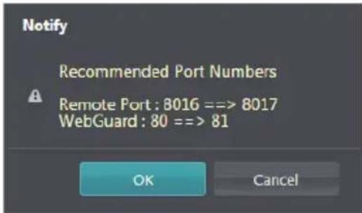
Click Apply to use the recommended port numbers.

- In a WAN environment, it is recommended that you use the UPnP function if you record video by using the FEN function or FEN connection is not smooth. Otherwise, monitoring or recording might not be smooth depending on the network environment.
• Each port number must be unique. - It is not allowed to use the same port number for more than one function.
- You can connect to the encoder using a media player that supports RTSP service and monitor its video feed. If the encoder is connected to the network via an IP router (or NAT) or is behind a firewall, you must open the ports. (All ports if using UDP protocol and RTSP ports if using TCP protocol) This feature may not be supported by all media player. In addition, video display on certain media players may not be smooth depending on the network status, video streaming compression method used, and/or the resolution setting.
Connection methods are as follows:
- Via PC: Launch the media player (such as VLC) and then enter rtsp://ID:Password@IP Address:RTSP Port Number/trackID='Stream Number'
(Stream Number: 1 if Primary, 2 if Secondary, and 3 if Tertiary). (e.g.: rtsp://admin:@10.0.152.35:554/trackID=1 (User: admin, Password: None, Encoder IP Address: 10.0.152.35, RTSP Port Number: 554, Stream: Primary)

- Port numbers of the remote program must be updated whenever the encoder's port numbers are changed.
- ONVIF protocol may not function if using HTTPS.
Bandwidth Control
Regulates the cnetwork bandwidth use based on network traffic fluctuations.
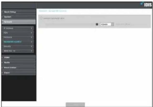
Select Network Bandwidth limit and then specify the maximum bandwidth. The device will not be able to use more than the specified limit in the event of network traffic.

It may not be possible to produce the frame rate specified under Video > Streaming if a network bandwidth limit has been set.
Security
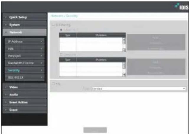
- IP Filtering: Select this option to enable IP Filtering. IP Filtering allows encoder access from certain IP addresses and blocks access from others.
- Add: Add new IP addresses to Allow List or Deny List. Select the Host option to add one IP address at a time. Select the Group option to define a range of IP addresses you wish to add.
- Remove/Remove All: Remove individual or all IP addresses from Allow List or Deny List.
- SSL: Select this option to enable SSL (Secure Sockets Layer). Enabling this option applies SSL protocol protection on data transmitted out. However, programs and systems that do not support SSL will not be able to connect to the encoder. If this option has been changed, click Save to apply the current settings, and then restart Remote Setup. If you do not restart Remote Setup, the changes afterwards will not be applied.

- Time server, FEN Server, and SMTP server's IP addresses must be added to Allow List under IP Filtering in order to use Time Sync, FEN, and Send Email features. No connection to the encoder will be permitted whatsoever from IP addresses added to Deny List.
- Enabling the SSL option may place a greater load on the external system, depending on the level of security being used.
- This product contains software developed by Open SSL Project for use in Open SSL Toolkit. (http://www.openssl.org/)
IEEE 802.1X
Select the IEEE 802.1X option to enable IEEE 802.1X network connection authentication.
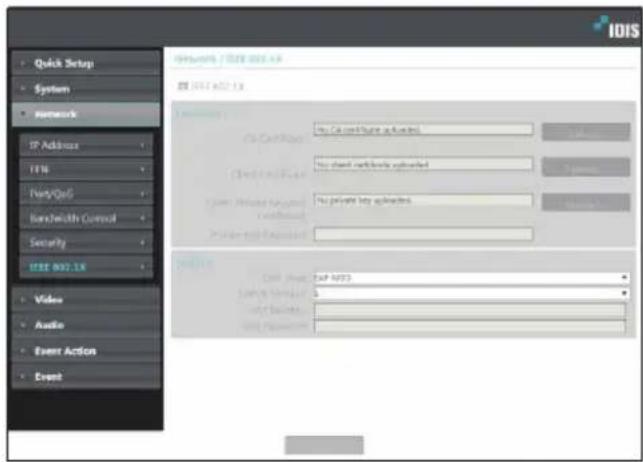
- Certificates: Upload a certificate or a private key. You may be prompted to enter a password for the private key.
-
Settings: Configure EAP (Extensible Authentication Protocol) settings.
-
EAP Type: Choose a network connection authentication method. Selected method must be identical to the authentication method used on the authentication server.
- EAPOL Version: Choose EAP authentication's version.
- EAP Identity/EAP Password: Enter authentication ID and password.

The authentication server and AP must support IEEE 802.1X authentication in order for the IEEE 802.1X network connection authentication feature to function properly.
Video
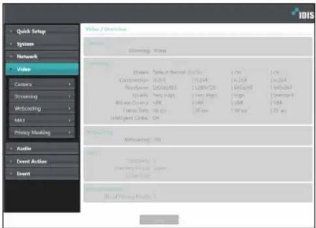
Configure Camera, Streaming, Webcasting, MAT, and Privacy Masking options.
Camera
Image Sensor
Configure Image Sensor settings.
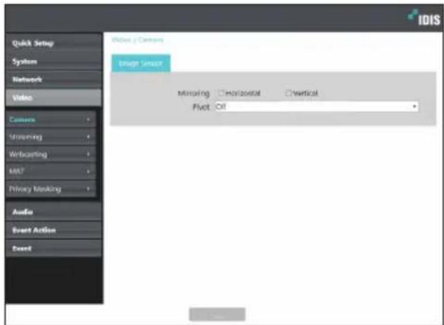
- Mirroring: Select Horizontal Reverse or Vertical Reverse to flip the image horizontally or vertically.
- Pivot: Select a direction to rotate images 90 degrees clockwise or counterclockwise. If both Mirroring and Pivot functions are enabled, Mirroring functions first, then Pivot.
Streaming
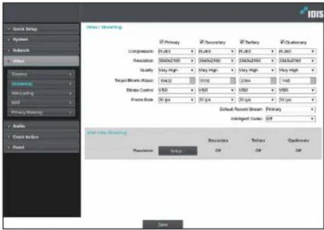
• Primary/Secondary/Tertiary/Quaternary
Multistreaming is supported. Enable/disable streaming use. The stream that you set up first has priority.
- Compression: Choose the streaming compression method.

When using H.265 compression, a device that does not support H.265 compression may prevent the screen from being displayed.
- Resolution: Choose a resolution setting for video streaming.
• Quality: Choose a quality setting for video streaming. - Target Bitrate(kbps): Set up the target bitrate. The bitrate value can be specified when the quality setting is a manual, and other settings display target bitrate for each quality setting.
- Bitrate Control: Choose a bitrate control mode for video compression.
- CBR (Fixed Bitrate): Maintains the current bitrate regardless of motion change in the video.
- VBR (Variable Bitrate): Bitrate varies depending on motion changes in the video. Less movement places less load on the network and takes up less storage space.
- Frame Rate: Choose a frame rate setting for video streaming.
- Default Record Stream: Choose a stream to use for recording. This setting, however, may not apply if a recording stream has been designated from the remote program or the SD memory card recording feature has been enabled.
- Intelligent Codec: Lower bitrate by using the intelligent codec.
- Multi-View Streaming: Designate a specific area of the screen and stream images from that area only. (not supported for the primary stream) Click Setup to designate a streaming area.
Select On and then specify the streaming area's resolution.
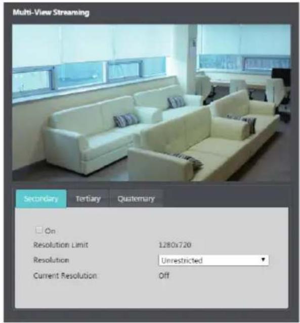
- Resolution Limit: Indicates the maximum resolution that can be set for the streaming area.
- Resolution: Designate a streaming area. Designated area is marked in red on the screen. You can adjust the resolution of the area or reposition the area by dragging and dropping using the mouse.
- Current Resolution: Displays the resolution of the designated streaming area.

If multiple users are connected to the device, the increase in bandwidth use can lower the frame rate.
Webcasting
Use the webcasting service to view live images from the encoder on a web site.
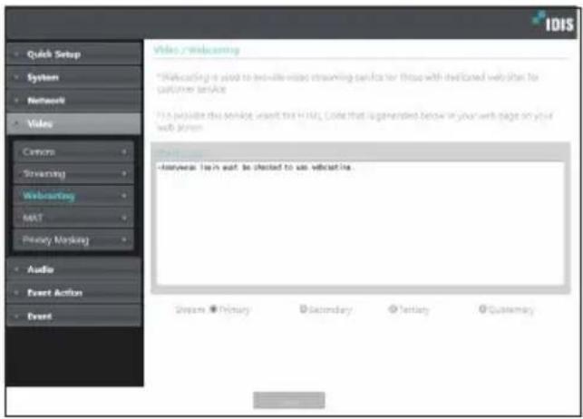
- HTML Code: Copy and paste the html code shown on the screen within the code of the web page you want the video to be displayed.
- Stream: Choose a stream to use for webcasting. Only a stream currently in use can be selected.

In order to use the webcasting service, the Allow Anonymous Login option under System > User/Group must be selected.
MAT
Select the MAT option to use the MAT (Motion Adaptive Transmission) feature during video transmission and recording.
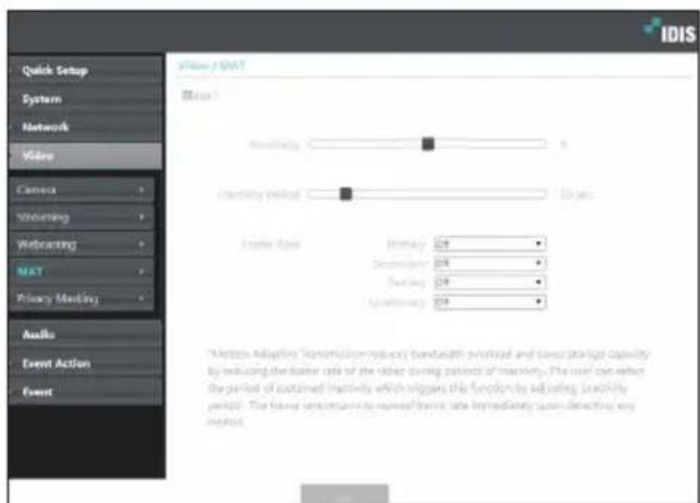
- Sensitivity: Set the motion detection sensitivity. Higher values will result in more sensitive motion detection.
- Inactivity Period: Set the Inactivity Period. If motion is not detected for the duration of time specified, video is transmitted and recorded using the frame rate designated below until movement is detected again.
- Frame Rate: Designate the frame rate to be used between the end of the Inactivity Period and the next motion detection. Video is transmitted and recorded at the designated frame rate between then end of the Inactivity Period and the next motion detection. Once motion is detected again, the frame rate designated under Streaming is restored immediately.

MAT (Motion Adaptive Transmission) is a feature that lowers the frame rate when motion is not detected to reduce the load on the network and save on storage space. Based on the specified sensitivity setting, no movement will be assumed if there is no change between two consecutive images.
Privacy Masking
Select Privacy Masking to set up a privacy mask over a specific area. The section on which a privacy mask is applied will appear as black when monitoring video.
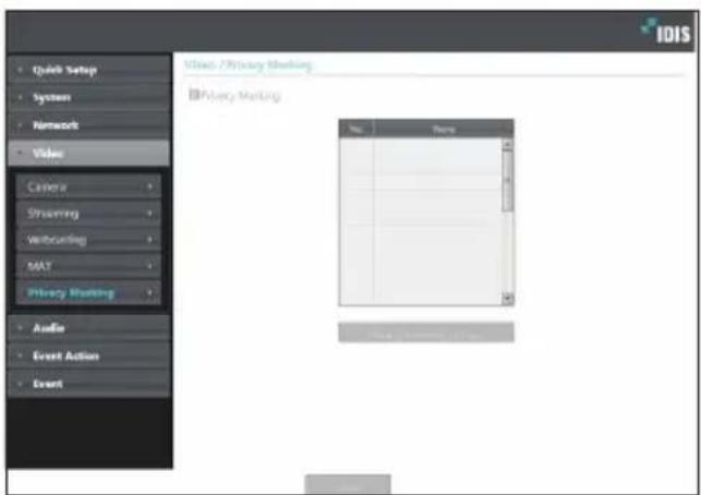
- Privacy Masking Setup: Set up privacy masks(up to 8).
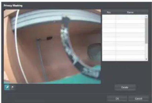
- (Select)/ (Unselect): Set or remove a privacy mask. Click on the button and drag & drop using the mouse to set up a privacy mask.
- No./Name: Displays a list of active privacy masks. The numbers indicate privacy mask numbers. Select the empty space next to a number to assign a name to the corresponding privacy mask. Click Delete to remove the selected privacy mask.
Audio
Configure audio in/out settings.
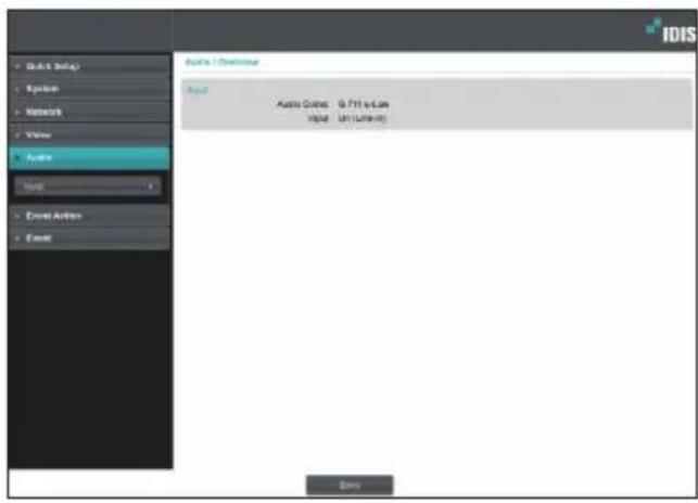
Input
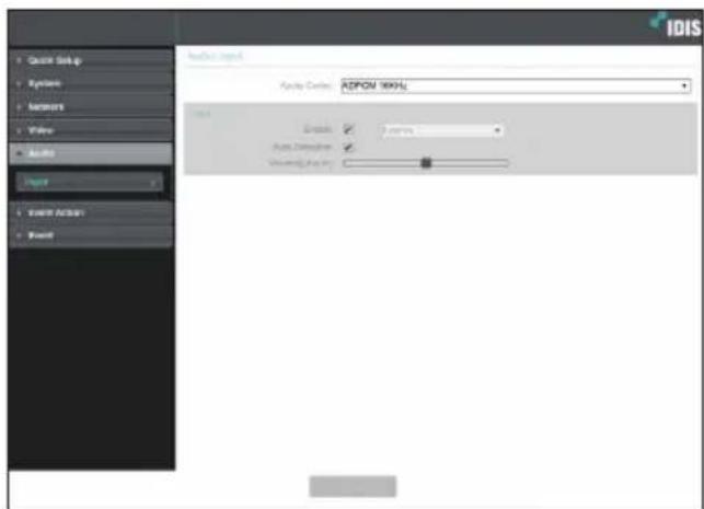
• Audio Codec: Select an audio codec.
- Input: Click Enable option to select audio input source (Line-in) and control the volume. When you select Auto Detection, the audio input device is automatically selected according to how audio is being input.
- Line-in: Audio input port on the rear panel of this encoder.
Event Action
Designate event detection alert actions.
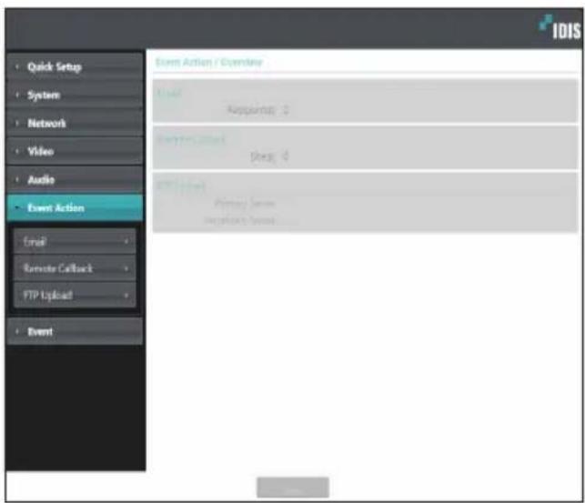
Select Email to send out emails.
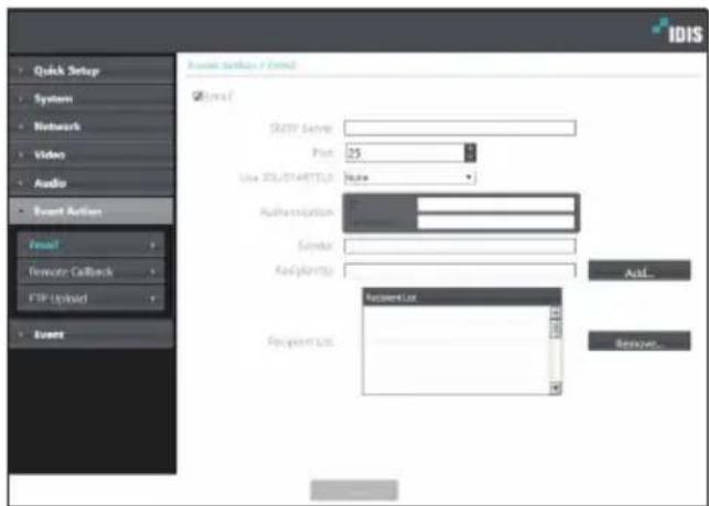
- SMTP Server/Port: Enter the SMTP server's IP address (or domain name) and port number you received from the network administrator. If a DNS server has been set up during network configuration, you can enter a domain name instead of an IP address.
- Use SSL/STARTTLS: If using an SMTP server requiring an SSL or STARTTLS connection, select SSL or STARTTLS option.
- Authentication: Enter a user ID and password if user authentication is required by the SMTP server.
- Sender/Recipient(s): Enter the sender and recipients' addresses. (Up to 10) The addresses must be properly formatted and include the @ symbol.
Remote Callback
Select Remote Callback to send callback messages to a remote system.

- Not supported from the IDIS Web program.
• The camera must be registered to the remote system in order to use the Remote Callback feature.
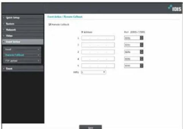
- IP Address: Enter the IP address and port number of the remote system that will receive the messages.
- Retry: Designate how many reattempts to make if message delivery fails.
FTP Upload
Select FTP Upload to upload .jpg image of the event detected to an FTP server.
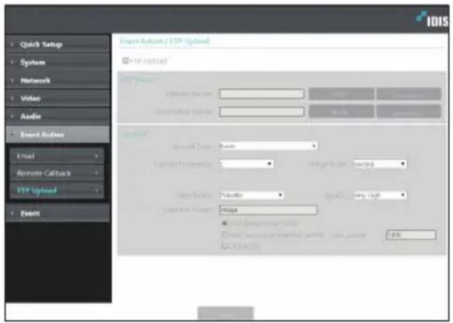
- FTP Server: Click Add to register a new FTP server. Click Remove to remove a registered FTP server. When an event is detected, a .jpg image of the event detected image is uploaded to the Primary Server. If the upload to the Primary Server fails, the file will be uploaded to the Secondary Server. Upload to the Secondary Server will continue to be attempted until successful. Fill out the fields below and click Test to test the FTP server connection settings. Once the test is complete, click OK.
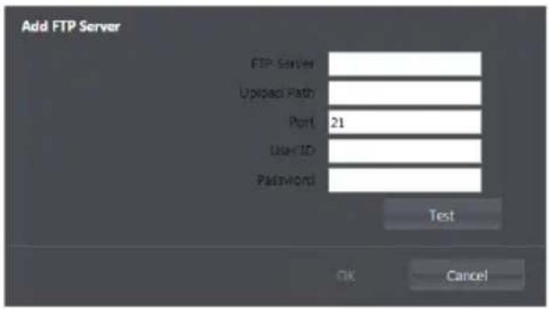
- FTP Server: Enter the FTP server's IP address (or domain name).
- Upload Path: Designate the file upload path.
- Port: Enter the FTP server's port number.
- User ID, Password: Enter the user ID and password needed for connecting to the FTP server.
- Settings: Configure image and upload settings.
- Upload Type: Choose an upload type. Select Always to upload images using the settings below, irrespective of event detection. Select Event to upload images using the settings below when an event is detected.
- Upload Frequency: Activated only when Upload Type has been set to Always. Designate the upload speed. The specified number of images will be uploaded to the FTP server during the specified period of time.
- Upload 1 image per: Activated only when Upload Type has been set to Event. Designate the upload speed. Select Upload for and specify a duration. Images will be uploaded for the specified duration at the specified upload speed. Select Upload while event status is active to upload images at the specified speed only while event status is active.
Part2 - Remote Setup
- Resolution/Quality: Choose the resolution and quality of the images to upload to the FTP server. Range of resolution settings you can use here can vary depending on the resolution setting applied under Video > Streaming.
- Base File Name: Enter a name for the files to be uploaded to the FTP server and then choose file identification options. Select Add Date/Time Suffix to add event detection date and time information to each image file. Select Add Sequence Number Suffix - max. Count to number the image files based on the order of event detection. Select Overwrite to overwrite the previous image with the new image. Event type is automatically added to the file names.

- When specifying the Upload Path or Base File Name, you cannot use special characters such as \/, #, *, |, :, ", <, >, and ?.
- The resolution of FTP upload image can change depending on the resolution setting applied under Video > Streaming.
- Set speed settings for Upload Frequency and Upload 1 image per options in consideration of the FTP server's performance. FTP uploads can fail if the configured speed is higher than what the FTP server can handle.
Event
Configure event detection settings.
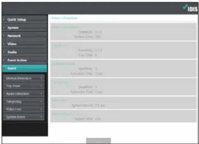
Motion Detection
Select Motion Detection to configure motion detection event settings. With motion detection event enabled, motion detections within the designated area will be assumed as events.
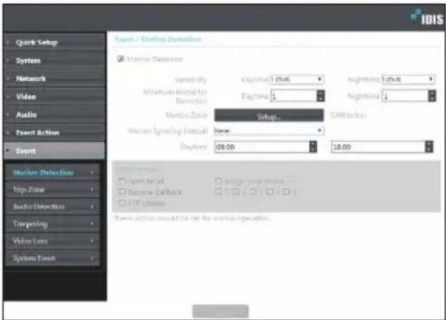
- Sensitivity: Select daytime and nighttime motion detection sensitivity levels. Higher values will result in more sensitive motion detection.
- Minimum Blocks for Detection: Select minimum blocks for daytime and nighttime motion detection. Motion must take place over the selected number of blocks in order for it to be considered as a motion detection event.
-
Motion Zone: Click Setup and define the motion zone using blocks.
-
(Select)/(Unselect): Enable/disable motion detection.
- (Single Block): Select/unselect motion detection blocks individually.
- ☑(Zone): Select/unselect multiple motion detection blocks.
-
⚫(All): Select/unselect all motion detection blocks
-
Motion Ignoring Interval: With Motion Ignoring Interval configured, no event log or notification is generated for motions detected during a period of time following a motion detection event.
- Daytime: Specify when daytime starts and ends. All other times will be assumed as nighttime.
-
Event Action: Select a motion detection event alert action.
-
Send Email: Select if you wish to send an email. Select the Image Attachment option to attach a .jpg image of the event detected to the email.
- Remote Callback: Select this option to send a message to a remote system and then select which system to send the message to.

• Not supported from the IDIS Web program.
- The camera must be registered to the remote system in order to use the Remote Callback feature.
- FTP Upload: Select this option if you wish to upload images to the FTP server.

Event Action settings must be configured correctly in order to perform event actions.
Trip-Zone
Select Trip-Zone to configure trip zone event settings. With trip zone event enabled, motion detected inside/outside the selected area will be assumed as an event.
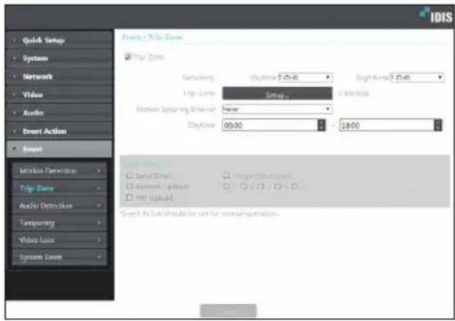
- Sensitivity: Select daytime and nighttime motion detection sensitivity levels. Higher values will result in more sensitive motion detection.
- Trip-Zone: Click Setup and define the trip zone using blocks.
- (Select)/(Unselect): Enable/disable trip zone.
- □ (Single Block): Select/unselect trip zone blocks individually.
- (Zone): Select/unselect multiple trip zone blocks.
- 📄(All): Select/unselect all trip zone blocks.
- Trip Direction: Define in which direction the motion has to occur in order for it to be considered as an event. Select In for movement occurring from outside the trip zone in and Out for movement occurring from inside the trip zone out.
- Motion Ignoring Interval: With Motion Ignoring Interval configured, no event log or notification is generated for motions detected during a period of time following a motion detection event.
- Daytime: Specify when daytime starts and ends. All other times will be assumed as nighttime.
• Event Action: Select a trip zone event alert action.
- Send Email: Select if you wish to send an email. Select the Image Attachment option to attach a .jpg image of the event detected to the email.
- Remote Callback: Select this option to send a message to a remote system and then select which system to send the message to.

- Not supported from the IDIS Web program.
- The camera must be registered to the remote system in order to use the Remote Callback feature.
- FTP Upload: Select this option if you wish to upload images to the FTP server.

Event Action settings must be configured correctly in order to perform event actions.
Audio Detection
Select Audio Detection to configure audio detection event settings. With audio detection enabled, an audio detection taking place during the specified activation period will be assumed as an event.
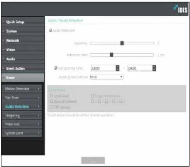
- Sensitivity: Define the audio detection sensitivity. Higher values will result in more sensitive detection.
- Activation Time: Specify how long audio has to be detected for it to be considered as an event. Audio detections that do not last for the specified duration of time will not be considered as events.
-
Use Ignoring Time: Define the event ignoring time. Audio detections taking place during the defined time range will not be assumed as events.
-
Audio Ignore Interval: With Audio Ignoring Time configured, no event log or notification is generated for audio detections taking place during a period of time following an audio detection event.
-
Event Action: Select an audio detection event alert action.
-
Send Email: Select if you wish to send an email. Select the Image Attachment option to attach a .jpg image of the event detected to the email.
- Remote Callback: Select this option to send a message to a remote system and then select which system to send the message to.

- Not supported from the IDIS Web program.
- The camera must be registered to the remote system in order to use the Remote Callback feature.
- FTP Upload: Select this option if you wish to upload images to the FTP server.

Event Action settings must be configured correctly in order to perform event actions.
Tampering
Select Tampering to configure tampering detection event settings. With tampering detection event enabled, a sudden change in the video, such as due to movement of the camera or covering up of the lens, will be assumed as an event.
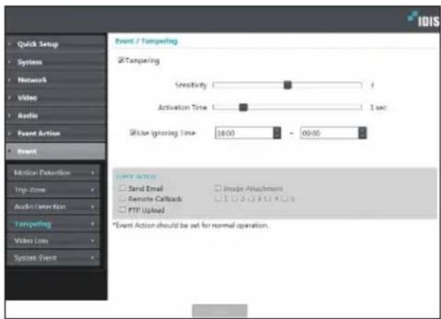
- Sensitivity: Define the tampering detection sensitivity. Higher values will result in more sensitive detection.
- Activation time: Specify how long tampering has to be detected for it to be considered as an event. Tampering detections that do not last for the specified duration of time will not be considered as events.
- Use Ignoring Time: Define the event ignoring time. Tampering detections taking place during the defined time range will not be assumed as events.
-
Event Action: Select a tampering detection event alert action.
-
Send Email: Select if you wish to send an email. Select the Image Attachment option to attach a .jpg image of the event detected to the email.
- Remote Callback: Select this option to send a message to a remote system and then select which system to send the message to.

• Not supported from the IDIS Web program.
- The camera must be registered to the remote system in order to use the Remote Callback feature.
- FTP Upload: Select this option if you wish to upload images to the FTP server.

Event Action settings must be configured correctly in order to perform event actions.
Video Loss
Select Video Loss and configure video loss settings.
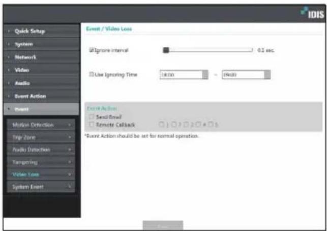
- Ignore Interval: The event occurs only when video loss occurs and remains for the specified duration. (For example, 0 sec.: Immediately, 15 sec.: 15 seconds)
-
Use Ignoring Time: The event never occurs for the specified duration even if video loss occurs.
• Event Action: Select a video loss event alert action. -
Send Email: Select to send an email.
- Remote Callback: Select this option to send a message to a remote system and then select which system to send the message to.

• Not supported from the IDIS Web program.
- The camera must be registered to the remote system in order to use the Remote Callback feature.

Event Action settings must be configured correctly in order to perform event actions.
System Event.
Select System Event and configure system event settings. With system event enabled, system status will be checked periodically and corresponding alerts will be generated.

- System Alive: Select to check the system status and then set up a schedule.
- Send Email: Select to send out an email when the system comes on line.
- Remote Callback: Select this option to send a message to a remote system when the system comes on line and then select which system to send the message to.

- Email and Remote Callback settings under Event Action must be configured correctly in order to send out emails and messages.
- Remote Callback is not supported on IDIS Web.
• The camera must be registered to the remote system in order to use the Remote Callback feature.
IDIS Web is a program that allows you to view video from remote locations over the Internet and can be accessed on a Microsoft Internet Explorer.
System requirements for running IDIS Web are as follows:
- OS: Microsoft Windows ^ 7 (Home Premium, Professional, Ultimate), Microsoft Windows ^ 8 (Pro, Enterprise) or Microsoft Windows ^ 10 (Home Pro)
• CPU: Intel Pentium IV 2.4GHz or above (Core 2 Duo E4600 recommended) - RAM: 1GB or more
• VGA: 128MB or more (1280x1024, 24bpp or above) - Internet Explorer: Version 10 or later 32-bit
1 Launch Internet Explorer and then enter the following information in the address bar.
– http://IP Address:Port Number (IDIS Web connection port number selected during camera IP address and port number setup)
– Or http://FEN Server Address/FEN name (FEN Server address and FEN name registered to the FEN Server)
- Or http://web.idisglobal.com (it is required to enter the camera IP address when logging in. If the camera uses the FEN feature, you can enter the FEN name registered to the FEN server instead of the camera IP address after selecting the USE FEN option)

- If the Use HTTPS option has been selected during IDIS Web port number setup, enter https instead of http. If prompted with a security certificate warning, select "Continue to this website (not recommended)." If the IDIS Web login page fails to load, configure Internet Explorer's settings as follows:
- Tools → Internet Options → Security → Custom Level... → Medium-high (default) or Medium.
- Tools → Internet Options → Advanced → Security → Use TLS 1.0 (select)
- If connecting by entering an IP address and a port number, you can connect by entering just the IP address if IDIS Web connection port number has been set to 80 (443 when entering https).
- If connecting by entering http://web.idisglobal.com, it is required to enter the Watch port number.
- Contact your network administrator for the IP address of the camera you wish to connect to the IDIS Web pot number.
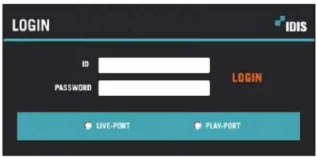
2 When prompted with the IDIS Web login window, select LIVE-PORT or PLAY-PORT as the desired mode. Enter the ID and password and click LOGIN to sign in using the selected mode.

• IDIS Web supports Microsoft Internet Explorer only and no other type of web browser.
- IDIS Web does not work with Microsoft*Windows* 8 metro UI.
- Do not close the login window while IDIS Web is running. Switching over to Web Live or Web Search mode can cause a script error, requiring you to restart the IDIS Web program.
- To use IDIS Web on Microsoft Windows Vista or above, launch Internet Explorer by right-clicking on the icon and selecting the Run as administrator option. Otherwise, certain IDIS Web functions might not be available.
- When running IDIS Web, the bottom section of the screen may get cut off if the address bar or the status bar is shown. In this case, change Internet Options so that the address bar or the status bar is hidden. (Tools → Internet Options → Security → Custom level... → Allow websites to open windows without address or status bars (Enable))
- Launching a new version of IDIS Web for the first time can cause Internet Explorer to load information from the previous version. In this case, navigate to Tools → Internet Options → General, delete temporary Internet files, and then restart IDIS Web.
- On Microsoft Windows Vista or above, lowered image transmission rate can prevent the screen from being displayed or updated. In this case, we recommend that you disable the computer's auto tuning function. Open the command prompt as an administrator. (Start → Accessories → Command Prompt → Right-Click and then select Run as administrator) Type in "netsh int tcp set global autotuninglevel=disable" and then press Enter. Restart the computer to apply the change. To enable auto tuning again, launch the command prompt as an administrator and then type in "netsh int tcp set global autotuninglevel=normal". Restart the computer to apply the change.
Web Live Mode
A remote web monitoring program that allows you to monitor images from remote locales in real-time.
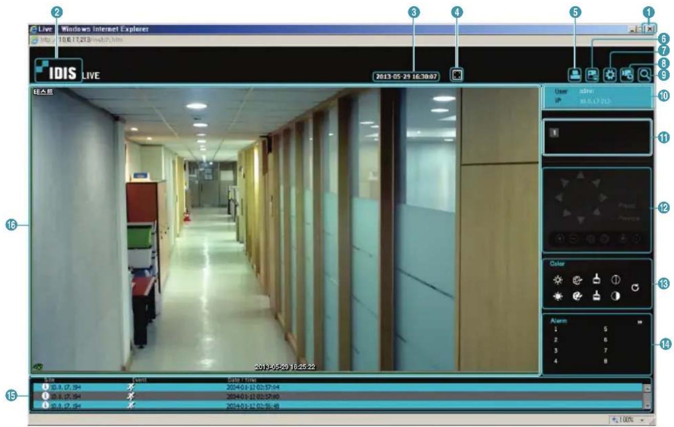
| 1 | Press ☒ to terminate IDIS Web. | |||
| 2 | Place the mouse pointer on the logo to check IDIS Web's version. | |||
| 3 | Displays the current time. | |||
| 4 | Click ☑ to view the video in full screen. Press the ESC key on the keyboard to return to the previous screen. | |||
| 5 | Click ☑ to print the current video screen using a printer connected to the computer. | |||
| 6 | Click ☑ to save the current video screen as an image file. | |||
| 7 | Click ☑ to configure rendering mode and OSD settings. Select rendering mode to adjust the video output rate or select which OSD elements to display on the screen from the OSD list. | |||
| 8 | Click ☑ to load the camera setup window. | |||
| 9 | Click ☑ to switch over to Web Search mode. | |||
| 10 | Shows login information. | |||
| 11 | Indicates the camera's number. | |||
| 12 | This function is not supported. | |||
| 13 | Used to adjust live video quality. | |||
| 14 | Click on to control the alarm out device connected to the camera. | |||
| 15 | Event status window at the bottom of the screen displays a list of events detected at remote locales. | |||
 | Enable/Disable Alarm In Tampering | [BYTT] | ||
 | Motion Detection Audio Detection | ### | ||
| ### | Trip zone | |||
| 16 | Right-click on the screen to display the pop-up menu. Click to enable or disable each function.· Change Camera Title: Used to change the camera's name. Renaming the camera in Web Live mode does not affect the camera's name on the remote system. If no name is entered for the camera, the name used at the remote locale is shown on the screen.· Enable Audio: Enables audio transmission with remote locales. Select to display buttons. Renaming the camera in Web Live mode does not affect the camera's name on the remote system. If no name is entered for the camera, the name used at the remote locale is shown on the screen.· Enable Audio: Enables audio transmission with remote locales. Select to display buttons. | |||
| S | Enables transmission of audio to the remote locale via microphone. | |||
| ### | Enables playback of audio from the remote locale on speakers. | |||
| S / Enables two-way audio communication with the remote locale. | ||||
| × | Disables audio transmission. | |||
 If the remote locale connected to supports audio transmission, icon appears on the corresponding camera screen.· Aspect Ratio: Change the aspect ratio of the video displayed on the screen.- Fit to Screen: Fit the video to the size of the camera screen.- Fit to Aspect Ratio: Resizes camera screen to original aspect ratio of the video.- Half Size (x0.5) - 4 Times Bigger (x4): Displays the camera videos in the selected size based on the original size of the video. For example, original size (x1) displays the video in its original size. Half size (x0.5) through 4 times larger (x4) options are only available if there is enough space on the camera screen to accommodate the selected size.· MultiStream: If the camera is running on multi-stream mode, you can choose between the streams.· Anti-Aliasing Screen: Removes stair step effect (blocks) that are caused when zooming a video to improve overall quality of video output.· Mouse PTZ Control: This function is not supported. If the remote locale connected to supports audio transmission, icon appears on the corresponding camera screen.· Aspect Ratio: Change the aspect ratio of the video displayed on the screen.- Fit to Screen: Fit the video to the size of the camera screen.- Fit to Aspect Ratio: Resizes camera screen to original aspect ratio of the video.- Half Size (x0.5) - 4 Times Bigger (x4): Displays the camera videos in the selected size based on the original size of the video. For example, original size (x1) displays the video in its original size. Half size (x0.5) through 4 times larger (x4) options are only available if there is enough space on the camera screen to accommodate the selected size.· MultiStream: If the camera is running on multi-stream mode, you can choose between the streams.· Anti-Aliasing Screen: Removes stair step effect (blocks) that are caused when zooming a video to improve overall quality of video output.· Mouse PTZ Control: This function is not supported. | ||||
| Change Camera TitleEnable Audio | ||
| Aspect Ratio | ▶ | |
| MultiStream | ▶ | |
| √ | Anti-Aliasing Screen | |
| Mouse PTZ Control | ||
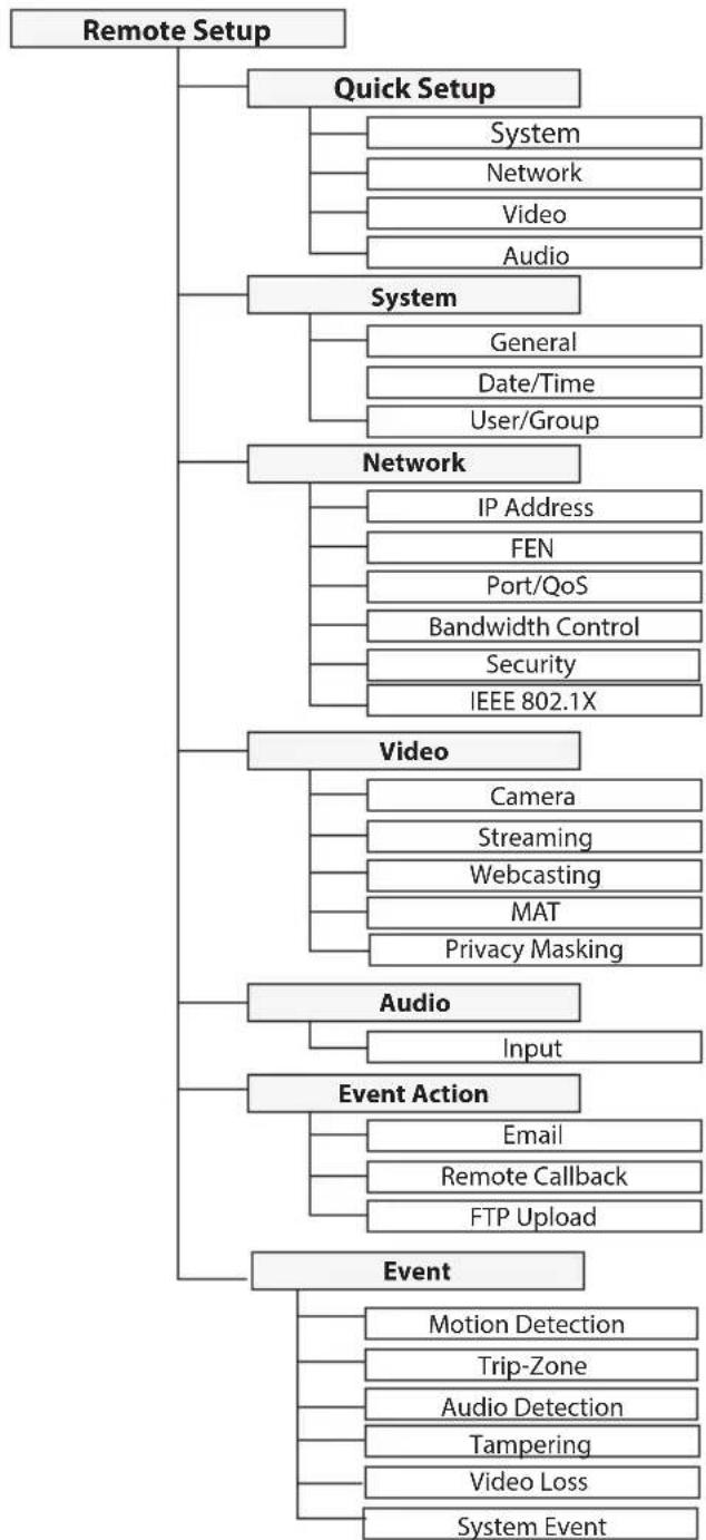
Setup Menu Tree (Remote Setup)
flowchart
graph TD
    A["Remote Setup"] --> B["Quick Setup"]
    B --> C["System"]
    B --> D["Network"]
    B --> E["Video"]
    B --> F["Audio"]
    A --> G["System"]
    G --> H["General"]
    G --> I["Date/Time"]
    G --> J["User/Group"]
    A --> K["Network"]
    K --> L["IP Address"]
    K --> M["FEN"]
    K --> N["Port/QoS"]
    K --> O["Bandwidth Control"]
    K --> P["Security"]
    K --> Q["IEEE 802.1X"]
    A --> R["Video"]
    R --> S["Camera"]
    R --> T["Streaming"]
    R --> U["Webcasting"]
    R --> V["MAT"]
    R --> W["Privacy Masking"]
    A --> X["Audio"]
    X --> Y["Input"]
    A --> Z["Event Action"]
    Z --> AA["Email"]
    Z --> AB["Remote Callback"]
    Z --> AC["FTP Upload"]
    A --> AD["Event"]
    AD --> AE["Motion Detection"]
    AD --> AF["Trip-Zone"]
    AD --> AG["Audio Detection"]
    AD --> AH["Tampering"]
    AD --> AI["Video Loss"]
    AD --> AJ["System Event"]
Troubleshooting
| Problem Check | |
| Power LED will not turn on | ·Check that the LAN cable is connected to the device supporting PSE.·Check that the power cable is connected or power supply status of the PSE device that the LAN cable is connected to.. |
| The system is unable to recognize network interface | ·Check the LAN cable.·Check the network LED. |
Specifications
| Model DP-HE1201 | |||
| Encoder | Input Video | HDMI x 1, VGA x 1 | |
| Output Video | HDMI x 1 (Input Bypass)VGA x 1 (Input Bypass) | ||
| Supported Input Resolution (HDMI) | 3840 x 2160, 1920 x 1080, 1600 x 1200, 1600 x 9001440 x 900, 1366 x 768, 1360 x 7681280 x 1024, 1280 x 960, 1280 x 8001280 x 768, 1280 x 720, 1024 x 768800 x 600, 720 x 480 | ||
| Supported Input Resolution (D-SUB(VGA)) | 1920 x 1080, 1600 x 1200, 1440 x 9001360 x 768, 1280 x 1024, 1280 x 8001280 x 720, 1024 x 768, 800 x 600 | ||
| Supported Input Resolution Standard (D-SUB) | VESA Display Monitor Timing | ||
| Supported Input Vertical Frequency | 3840 x 2160 : 30Hz, others : 60Hz | ||
| Network | DirectIP Mode Compatibility Mode | ||
| Video Compression H.265, H.264 (MP), M-JPEG | |||
| Bitrate Control H.264 - CBR / VBR, H.265 - CBR / VBR | |||
| Audio Compression ADPCM 16K, G.726, G.711 u-Law, G.711 a-Law | |||
| Max. Frame Rate 30ips : 3840 x 2160 | |||
| Supported Resolution 1920x1080, 1280x720, 704x480, 640x360 | |||
Part 4 - Appendix
| Bit rate(640x360 @30ips)- Very High / High / Standard / Basic | H.264 - 3Mbps / 2.25Mbps / 1.5Mbps / 0.75MbpsH.265 - 1.5Mbps / 1.125Mbps / 0.75Mbps / 0.375Mbps | ||
| Bit rate(704x480 @30ips)- Very High / High / Standard / Basic | H.264 - 4Mbps / 3Mbps / 2Mbps / 1MbpsH.265 - 2Mbps / 1.5Mbps / 1Mbps / 0.5Mbps | ||
| Bit rate(720P @30ips)- Very High / High / Standard / Basic | H.264 - 8Mbps / 6Mbps / 4Mbps / 2MbpsH.265 - 4Mbps / 3Mbps / 2Mbps / 1Mbps | ||
| Bit rate(FHD @30ips)- Very High / High / Standard / Basic | H.264 - 12Mbps / 10Mbps / 8Mbps / 4MbpsH.265 - 6Mbps / 5Mbps / 4Mbps / 2Mbps | H.264 - 12Mbps / 10Mbps / 8Mbps / 4MbpsH.265 - 6Mbps / 5Mbps / 4Mbps / 2Mbps | |
| Bit rate(UHD @30ips)- Very High / High / Standard / Basic | H.264 - 18Mbps / 15Mbps / 12Mbps / 9MbpsH.265 - 9Mbps / 7.5Mbps / 6Mbps / 4.5Mbps | ||
| Multi-video Streaming Quadruple Streaming | |||
| Ethernet RJ45 (10/100BASE-T) | |||
| Electrical | Power Source 12V | =, PoE (IEEE 802.3af Class 3) | |
| Power Consumption | 12V=0.95A, 11.4WPoE, IEEE 802.3af(Class 3) | ||
| Approval FCC, CE, KC | |||
| Mechanical | Dimensions (W x H x D) 200mm x 44mm x 152.3mm (2.98" x 2.4" x 5.09") | ||
| Weight 800g (1.72 lb) | |||
IDIS®
- HDMI & VGA Video Encoder
- Before reading this manual
- Safety Precautions
- CAUTION
- Important Safeguards
- Read Instructions
- Retain Instructions
- Cleaning
- Attachments
- Water and/or Moisture
- Ventilation
- Accessories
- Power Sources
- Power Cord
- Lightning
- Overloading
- Objects and Liquids
- Servicing
- Damage requiring Service
- Replacement Parts
- Safety Check
- Field Installation
- Correct Batteries
- Tmra
- Elevated Operating Ambient Temperature
- Reduced Air Flow
- Mechanical Loading
- Circuit Overloading
- Reliable Earthing (Grounding)
- FIn-Text
- Symbol Type Description
- User's Caution Statement
- FCC Compliance Statement
- WEEE (Waste Electrical & Electronic Equipment)
- Correct Disposal of This Product
- Copyright
- Registered Trademarks
- 1
- Part 1 - Introduction....8
- 2
- Part2 - Remote Setup .... 13
- 4
- Part 3 - IDIS Web .... 3 6
- Part 4 - Appendix....40
- Product Features
- Video Encoder Connection Diagram
- Accessories
- Overview
- Front Panel
- ① Power LED
- ② Network LED
- ③ Factory Reset Switch
- Rear Panel
- ① DC12V In
- ② Network + PoE Power In
- ③ USB-B
- ④ Audio In/Out
- ⑤ HDMI Input
- Part 1 - Introduction
- ⑥ HDMI Output
- ⑦ VGA Input
- ⑧ VGA Output
- Part2 - Remote Setup
- USB Remote Control (Keyboard/Mouse)
- Remote Setup
- Quick Setup
- System
- General
- - Miscellaneous
- - ONVIF Event Type
- - Setup
- Date/Time
- - Time Sync
- User/Group
- Remote Control
- Network
- IP Address
- FEN
- Port/QoS
- Bandwidth Control
- Security
- IEEE 802.1X
- Video
- Camera
- Image Sensor
- Streaming
- Webcasting
- MAT
- Privacy Masking
- Audio
- Input
- Event Action
- Remote Callback
- FTP Upload
- Event
- Motion Detection
- Trip-Zone
- Audio Detection
- Tampering
- Video Loss
- System Event.
- Web Live Mode
- Troubleshooting
- Specifications
- IDIS®
Brand : IDIS
Model : DP-HE1201
Category : Uncategorized