
LYNX-MIX124UM - Hand blender ALTO - Free user manual and instructions
Find the device manual for free LYNX-MIX124UM ALTO in PDF.


| Product Type | 12-input compact analog mixer with digital effects |
| Model | LYNX-MIX124UM |
| Dimensions (W×D×H) | 415 mm × 400 mm × 38/115 mm |
| Weight | 6.7 kg (14.8 lb) |
| Power Supply | 100-120 VAC 60Hz or 210-240 VAC 50Hz, 40W |
| Fuse | T1.25 AL |
| Input Channels | 6 mono MIC/LINE (XLR & TRS), 4 stereo LINE (TRS) |
| Phantom Power | +48V, switchable, on XLR inputs |
| Digital Effects | 24-bit, 256 presets (16 presets × 16 variations) |
| Equalization | Mono: 3-band with sweepable MID; Stereo: 4-band fixed (HI, HI-MID, MID-LOW, LOW) |
| MP3 Player | USB port, supports MP3 playback (FAT16/32), up to 7 folder levels |
| AUX Sends | 4 per channel (2 pre/post switchable, 2 post), 4 master AUX sends |
| Subgroups | 4 subgroups (SUB1-2, SUB3-4) with assign switches |
| Insert Points | Mono channel inserts (CH1-4), main insert, subgroup inserts |
| Direct Outputs | CH1-4 direct out (TRS) |
| Control Room/Phones | Separate level controls, source selection (MAIN, SUB, 2TK) |
| Outputs | Main mix XLR & TRS, mono out, control room out, tape out, DFX out |
| Frequency Response | 10 Hz - 55 kHz ±3 dB |
| Total Harmonic Distortion | < 0.005% at +4 dBu, 1 kHz |
| Signal-to-Noise Ratio | > 115 dB (mic preamp) |
| Cleaning | Use only a dry cloth; do not use solvents or chemicals |
| Warranty | 1 year from purchase date (with registration) |
Frequently Asked Questions - LYNX-MIX124UM ALTO
User questions about LYNX-MIX124UM ALTO
0 question about this device. Answer the ones you know or ask your own.
Ask a new question about this device
Download the instructions for your Hand blender in PDF format for free! Find your manual LYNX-MIX124UM - ALTO and take your electronic device back in hand. On this page are published all the documents necessary for the use of your device. LYNX-MIX124UM by ALTO.
USER MANUAL LYNX-MIX124UM ALTO
natural_image
Interior view of a mechanical audio workstation with multiple input switches and control panels (no visible text or labels)www.altoproaudio.com
Version 1.2 DEC. 2009
English
IMPORTANT SAFETY INSTRUCTION

CAUTION
RISK OF ELECTRIC SHOCK DO NOT OPEN

TO REDUCE THE RISK OF ELECTRIC SHOCK PLEASE DO NOT REMOVE THE COVER OR THE BACK PANEL OF THIS EQUIPMENT. THERE ARE NO PARTS NEEDED BY USER INSIDE THE EQUIPMENT. FOR SERVICE, PLEASE CONTACT QUALIFIED SERVICE CENTERS.
This symbol, wherever used, alerts you to the presence of un-insulated and dangerous voltages within the product enclosure. These are voltages that may be sufficient to constitute the risk of electric shock or death.
This symbol, wherever used, alerts you to important operating and maintenance instructions. Please read.
Protective Ground Terminal ã AC mains (Alternating Current) Hazardous Live Terminal
ON: Denotes the product is turned on. OFF: Denotes the product is turned off.
CAUTION
Describes precautions that should be observed to prevent damage to the product.
-
Read this Manual carefully before operation.
-
Keep this Manual in a safe place.
-
Be aware of all warnings reported with this symbol.
-
Keep this Equipment away from water and moisture.
-
Clean it only with dry cloth. Do not use solvent or other chemicals.
-
Do not damp or cover any cooling opening. Install the equipment only in accordance with the Manufacturer's instructions.
-
Power Cords are designed for your safety. Do not remove Ground connections! If the plug does not fit your AC outlet, seek advice from a qualified electrician. Protect the power cord and plug from any physical stress to avoid risk of electric shock. Do not place heavy objects on the power cord. This could cause electric shock or fire.
-
Unplug this equipment when unused for long periods of time or during a storm.
-
Refer all service to qualified service personnel only. Do not perform any servicing other than those instructions contained within the User's Manual.
-
To prevent fire and damage to the product, use only the recommended fuse type as indicated in this manual. Do not short-circuit the fuse holder. Before replacing the fuse, make sure that the product is OFF and disconnected from the AC outlet.
WARNING
To reduce the risk of electric shock and fire, do not expose this equipment to moisture or rain.

Dispose of this product should not be placed in municipal area and should be separate collection.
- Movethis Equipment only with a car stand, tripod, or bracket,
specified by the manufacturer, or sold with the Equipment. When a cart is used, use caution when moving the cart / equipment combination to avoid possible injury from tip-over

natural_image
Symbolic icon of a person pushing a large rectangular block, enclosed in a circular frame with a diagonal line (no text or symbols)- Permanent hearing loss may be caused by exposure to \ extremely high noise levels. The US. Government's Occupational Safety and Health Administration (OSHA) has specified the permissible exposure to noise level. These are shown in the following chart:
HOURS X DAY SPL EXAMPLE
| 8 | 90 | Small gig |
| 6 | 92 | train |
| 4 | 95 | Subway train |
| 3 | 97 | High level desktop monitors |
| 2 | 100 | Classic music concert |
| 1,5 | 102 | |
| 1 | 105 | |
| 0,5 | 110 | |
| 0,25 or less | 115 | Rock concert |
According to OSHA, an exposure to high SPL in excess of these limits may result in the loss of heat. To avoid the potential damage of heat, it is recommended that Personnel exposed to equipment capable of generating high SPL use hearing protection while such equipment is under operation.
The apparatus shall be connected to a mains socket outlet with a protective earthing connection.
The mains plug or an appliance coupler is used as the disconnect device, the disconnect device shall remain readily operable.
IN THIS MANUAL
- INTRODUCTION....1
- FEATURES....1
- QUICK START....4
- CONTROL ELEMENTS....5
- INSTALLATION & CONNECTION....16
- OPERATION INSTRUCTION FOR MP3....19
- PRESET LIST....22
- BLOCK DIAGRAM....23
- TECHNICAL SPECIFICATIONS....24
- WARRANTY....25
1. INTRODUCTION
Thank you for purchasing the 12-inputs ▲LTO LYNX-MIX 124UM compact mixer. Your LYNX-MIX 124UM is a remarkable compact mixer that doesn't find many equals in the market today, with 6 MIC and 4 Stereo Line-level inputs for serious live performances. Your LYNX-MIX 124UM includes a 24-bit digital multi-effect with 16 Factory Presets and 16 variations for every preset, for a total of 256 different digital effects. It has a 3-band sweepable MID EQ on mono input channels, 4-band EQ on stereo input channels. It also features MP3 player function, it can connect with the external USB interface, insert the MP3 & WAV file of the MP3 USB disk for playback, and it supports root directory reading and storing functions. All the above features and its audio quality, make it perfect for piano bar, karaoke, as well as fixed PA installation. Enjoy your LYNX-MIX 124UM and please carefully read this Manual before operation!
2. FEATURES
¶ 6 MIC inputs with gold plated XLR and balanced TRS jack
¶ 4 Stereo input channels with balanced TRS jacks
Ultra-low noise discrete MIC preamps with +48 V Phantom Power
SUB1-2, SUB3-4 & MAIN L-R signal assignment switches
4 AUX Sends per channel: 2 PRE/POST faders switchable for monitoring application effects & sound processor input; 2 POST faders as external send or for internal digital DFX
3-band EQ with sweepable MID on mono inputs; 4-band EQ on stereo inputs
Channel Inserts and Direct Outputs on each mono channel plus Main Inserts for flexible connection of outboard equipment
24-bit internal DSP with 256 effects, 16 presets by 16 variations with DSP Mute switch and Peak LED
2-TRACK IN assignable to Main Mix, Control Room/Headphone outputs
MP3 player functions


LARGE GIG HOOKUP DIAGRAM

flowchart
graph TD
    A["USB Driver"] --> B["CD PLAYER"]
    B --> C["Wireless MICROPHONE 2"]
    C --> D["MIC 1 MIC 2"]
    D --> E["MIU 1"]
    C --> F["MIC 3"]
    F --> G["MIU 3"]
    C --> H["MIC 4"]
    H --> I["MIU 4"]
    C --> J["MIC 5"]
    J --> K["MIU 5"]
    C --> L["MIC 6"]
    L --> M["2-TRACK ON/OUT"]
    M --> N["TAPS ON TAPS OUT"]
    N --> O["MP3 PLAYER"]
    O --> P["24BITS DIGITAL STUDIO EFFECTS PROCESSOR"]
    O --> Q["KEYBOARD"]
    O --> R["HEADPHONE"]
    S["GUITAR"] --> T["D/I BOX"]
    U["BASS"] --> V["DRUM MACHINE"]
    W["DRUM MACHINE"] --> X["KEYBOARD"]
    Y["DRUM MACHINE"] --> Z["HEADPHONE"]

flowchart
graph TD
    A["COMPUTER"] --> B["ACTIVE STUDIO MONITORS"]
    B --> C["AUX SERIES"]
    C --> D["CND/CHN/CHN/CHN"]
    C --> E["SUBGROUPS INSERT"]
    C --> F["CD PLAYER"]
    B --> G["OUTPUT/OUTPUT/OUTPUT/RNA/CIRCUA"]
    B --> H["MAIN VIE OUTPUT/MAIN/RNA/CIRCUA"]
    B --> I["USB"]
    B --> J["MAIN VIE OUTPUT/MAIN/RNA/CIRCUA"]
    B --> K["OUTPUT/RNA/CIRCUA"]
    B --> L["AUX RANK"]
    B --> M["AUX RANK"]
    B --> N["AUX RANK"]
    B --> O["AUX RANK"]
    B --> P["AUX RANK"]
    B --> Q["AUX RANK"]
    B --> R["AUX RANK"]
    B --> S["AUX RANK"]
    B --> T["AUX RANK"]
    B --> U["AUX RANK"]
    B --> V["AUX RANK"]
    B --> W["AUX RANK"]
    B --> X["AUX RANK"]
    B --> Y["AUX RANK"]
    B --> Z["AUX RANK"]
    B --> AA["AUX RANK"]
    B --> AB["AUX RANK"]
    B --> AC["AUX RANK"]
    B --> AD["AUX RANK"]
    B --> AE["AUX RANK"]
This is the fastest way to get something out from your LYNX-MIX124UM, if you have a keyboard and a microphone.
a. Plug the microphone into Channel 1 MIC IN.
b. Turn down AUX and LEVEL controls on the input channel.
c. Put the EQ controls on center position.
d. Connect 2 passive cabinets to the rear speaker cabinets.
e. Turn on your LYNX-MIX124UM.
f. Sing or speak into the microphone with normal volume and adjust the channel LEVEL control of half.
g. If you like, you can adjust the EQ at this stage.
h. The LED on the Master LED meter should flash only occasionally, otherwise you will hear distortion. If this LED is not active and you still hear distortion, please turn down a little the input LEVEL control or reduce the output level of your source instrument.
i. Connect your stereo keyboard into channel 5/6 and repeat the sequence.
Hereyouare.ItisyourfirstgigwithyourLYNX-MIX124UM.

4. CONTROL ELEMENTS
1 MONO MIC/LINE Channels
Your LYNX-MIX 124UM is equipped with 4 low-noise microphone preamplifier with optional phantom power, 50 dB of Gain and over 115 dB of S/N ratio. You can connect almost any type of microphone. Dynamic microphones do not need phantom power. Use phantom power for condenser microphones only, but make sure that the phantom power button is disengaged before connecting the microphone. Phantom power will not damage your dynamic balanced microphones, so make sure to read the MIC instructions manual before engaging phantom power. Use switch (48) to activate/deactivate phantom power. These channels are also equipped with 1/4" TRS balanced/unbalanced LINE-IN plugs to connect line-level instruments such as keyboards, drum machines and effect devices.
2 STEREO INPUTS
These are channels 5 through 12. They are organised in stereo pair and provided with XLR sockets (channels 5/6) and 1/4" TRS phone jacks. If you connect the left jack only, the input will operate in mono mode, so the left input signal will appear on both input channels. You can use these inputs with a stereo keyboard, drum machine, etc.
3 MONO Channel INSERT
This is where you connect external sound processors such as compressor-limiter, equalizers, etc.. The insert point is available on the first 4 mono MIC channels only.
4 TRIM
The TRIM control is applied in the mono MIC and stereo input channels. It provides with 2 different indications: One is for the MIC and the other for LINE levels. When you use a microphone, you shall read the MIC ring (0\~50 for mono MIC input, 0\~40 for stereo channels); when you use a line level instrument, you shall read the LINE ring (+15\~-35 dB for mono MIC input, +20\~-20 dB for stereo channels). For optimum operation, you shall set this control in a way that the PEAK LED (17) blinks only occasionally in order to avoid input channel distortion.



4. CONTROL ELEMENTS
5 LINE GAIN
When you use a line level instrument, you shall read the ring (-20\~+20 dB). For optimum operation, you shall set this control in a way that the PEAK LED (17) signal peaks only, thus avoiding input channel distortion.
6 LEVEL SET LED
This LED will help you to easily detect the input level, thus making much faster the research of distorted signals.
7 LOW-CUT Button
By pressing this button, you will activate a 75 Hz low frequency filter with a slope of 18 dB per octave. You can use this facility to reduce the hum noise infected by the mains power supply, or the stage rumble while using a microphone.


8 LINE/MP3 Button
By pressing this button, it will switch to the MP3 mode, then the Mp3 signal can be sent to this channel or the Main Mix channel; by releasing this button, the LINE IN inputs signal will send to the line input channels.
9 LINE/USB Button
By pressing this button, it will switch to the USB mode, then the USB signal can be sent to this channel or the Main Mix channel; by releasing this button, the LINE IN inputs signal will send to the line input channels.
EQUALISER
There are 3-band EQ with sweepable MID on all mono input channel1-4: HI, MID and LOW band. There are 4-band fixed frequency EQ on the stereo channel 5-12: HI, HI-MID, MID-LOW and LOW band. All bands provide up to 15 dB of boost or cut.
10 HI
If you turn this control up, you will boost all the frequencies above 12 kHz (shelving filter). You will add transparency to vocals and guitar and also make cymbals crispier. Turn the control down to cut all frequencies above 12 kHz. In such way, you can reduce human voice sibilances or reduce a tape player hiss.

4. CONTROL ELEMENTS
11 MID
This is a peaking filter and it will boost/cut frequencies from 100 Hz to 8 kHz depending on the position of the MID freq control. Setting the frequency control on lower frequencies, this control will affect the range of fundamental frequencies of most instruments, including human voices, as well as some
harmonics when set to higher frequencies.
12 HI-MID
This control gives you up to 15 dB boost or cut at 3 kHz. It is useful for controlling voice, making the performance brighter.
13 MID-LOW
This control gives you up to 15 dB boost or cut at 500 Hz.
14 LOW
Turning this control up, all the frequencies below 80 Hz will be boosted. You will give more punch to bass drum and bass guitar and make the vocalist more "macho". Turning it down, you will cut all the frequencies below 80Hz. In this way, you can avoid low-frequency vibrations and resonance thus preserving the life of your woofers.
15 AUX SENDS Level Control
These four controls are used to adjust the level of the respective signal sent to AUX bus, AUX1 and AUX2 can be switched to PRE/POST-FADER via the PRE/POST button, so, generally, they're used PRE-FADER for monitor application and POST-FADER for effect units. AUX3 and AUX4 are configured as POST-Faders. Generally speaking, the users of this unit will use the onboard DSP effect module setting AUX send 4. Alternatively, it's possible to connect an external effect unit input to EFX2 SEND connector.
16 PAN/BAL Control
Abbreviation of PANORAMA control for mono channels, allowing to set the stereo signal front. Keeping this control in central position, the signal will be equal in both Left and Right speakers. Stereo channels have BALANCE control, similar to your hi-fi set control.

17 PEAK LED
Inside your LYNX-MIX 124UM mixer, the audio signal is treated in several different stages and then sent to the PEAK LED. When the LED is red illuminated, it warns you that you are reaching signal saturation and possible distortion. In order to avoid distortion you should reduce the GAIN, EQ, or LEVEL settings.
18 MUTE Button & LED
Each channel is equipped with a MUTE button. Pressing this button is equal to turning the fader down, which can mute the corresponding channel output except for the channel INSERT send and SOLO (in PFL mode). And the MUTE LED will illuminate.
19 ASSIGNMENT Controls
Each channel provides four push-buttons: SUB1-2, SUB3-4, MAIN L-R and SOLO. Pressing the SOLO button, the corresponding SOLO LED will illuminate and the SOLO signal will replace other signals send to the Headphone/Control Room and Meters. Usually use the SOLO function in live work to preview channels before they are let into the mix. It is useful to set an instrument's input level and EQ, and you can also solo any channel that you want to. The SOLO switch never affects any mix other than the Control Room. The other three buttons are signal assignment switches. Pressing the SUB1-2 will assign the channel signal to Subgroup1/2, using the PAN knob you can adjust the amount of channel signal sent to the SUB1 versus SUB2, completely turning the Pan to left, the signal will be addressed to Subgroup1 only and vice-versa. In the same way, pressing the SUB3-4 or MAIN L/R will assign the channel signal to Subgroup3/4 or MAIN MIX L/R, and this setting too will be affected by PAN.
20 FADER
This fader will adjust the overall level of this channel and set the amount of signal send to SUB1-2, SUB3-4, and MAIN L-R outputs.
21 Control Room Source
You can choose to monitor any combination of MAIN MIX, SUB1-2, SUB 3-4 and 2TK IN via these Matrix switches. Engaging these switches, the stereo signals will be delivered to the Phones, Control Room and Meters display.
※NOTE: When any SOLO switch was engaged, the SOLO signal will replace other signals, and that signal will be present to Control Room, Phones, and Meters.
22 PHONES/CTRL ROOM Controls
Rotate these knobs to independently adjust the stereo level of CTRL ROOM and PHONES-these levels should adjusted from -∞ to MAX.

4. CONTROL ELEMENTS
23 Master AUX SENDS Controls
These four controls are used to determine the master AUX SEND levels, which can be varied from -∞ to +15 dB. Connecting to your mixer an external effect units with no input gain control, you can get a further +15 dB gain available from these Aux Send outputs. In the same way, AUX4 Master control will provide the needed level adjustment for the internal effect unit.
24 SOLO Button
The function of these SOLO buttons is similar to channel SOLO buttons. Pressing any SOLO button, the corresponding AUX send will be routed to the Ctrl Room/Phones outputs and Meters display.
25 Master STEREO AUX RETURNS Controls
These four controls set the level of effects received by stereo AUX RETURN connectors, which can be varied from - to +15 dB. They are used to provide the further gain for low level effects.
26 TO AUX SEND1/2
Both these rotary knobs assign the AUX RETURN signals to their respective AUX SEND outputs: The "TO AUX SEND1" assign the signal from AUX RETURN1 to AUX SEND1 bus, and "TO AUX SEND2" assign the signal from AUX RETURN2 to AUX SEND2 bus. The adjustable range goes from -do +15 dB.
27 MAIN MIX & CTRL/R Button
AUX RETURN3 is equipped with the Main Mix & Ctrl/R button. Release the button to send the stereo signal from AUX RETURN3 to MAIN MIX buses; Engage the button, then the stereo signal will be sent to CTRL/R output.

28 SUB1-2/SUB3-4/MAIN MIX Buttons
These three buttons are configured for AUX RETURN4, they can be regarded as the signal assignment switches. When engaging the SUB1-2, the stereo signal from AUX RETURN4 will be assigned to Subgroup1/2; in the same way, pressing SUB3-4 the signal will be assigned to Subgroup3/4, and pressing MAIN MIX it will be assigned to MAIN MIX buses.
29 AUX RETURNS SOLO Button
The function of AUX RETURN SOLO is like the channel SOLO button. Engaging this switch signal from AUX RETURN (1-4) will be sent to CTRL OUT, PHONES outputs and Meters display. Pressing this button, the LED next to the button will light. This feature is affected by SOLO mode button (n.35).
30 SUBGROUPS ASSIGN TO MAIN MIX
Through these switches, you can operate the subgroup faders as a master controls assigning the subgroup signals to MAIN MIX. Engage the LEFT switch to send the corresponding subgroup signal to MAIN MIX L, and the RIGHT switch for MAIN MIX R. When engaging the both switches, the signal will be sent to L/R of MAIN MIX.
31 SUBGROUPS Fader
These faders are used to control the levels of the signal send to the SUB-GROUPS OUT, the adjustable range goes from - to +10 dB. Any channel that is assigned to the subgroups, not muted and not turned down will be assigned to the SUB OUTS.
This fader sets the amount of signal send either to the Main Mix Output and to the Tape Output.
33 LED Meter
The stereo 12-segment LED Meter shows the level of signal send to Ctrl Room and Phones outputs.
34 2TK TO MIX Button
Engaging this switch allows you to combine the 2-Track output with the Main Mix. In other words, feeds the 2-Track In signals into Main L/R output. after the Level control, otherwise, release the button will output the soloed signal before the Level control.
※NOTE: The SOLO function will never affect sound output to main recording output, and also can't be affected by channel's MUTE switch.
4. CONTROL ELEMENTS
35 SOLO MODE Button
This button provides two modes: up for PFL (Pre-Fader-Listen) mode, down for AFL (After-Fader-Listen) mode.
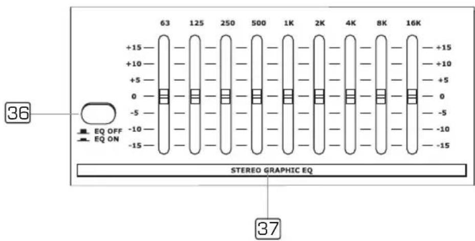
36 EQ Switch
Engage this button to include the stereo graphic EQ in ST OUT output circuit. It can be used to modify the overall sound character of your mix. If you release the button, the stereo graphic EQ will be bypassed.
37 STEREO GRAPHIC EQ
Each one of these faders will boost or attenuate (+/-15 dB) the selected frequency at a preset bandwidth. When all the faders are in center position, the output of the equalizer is flat response.
DSP SECTION
There is a powerful 24-bit/256 preset multi-effects included in your LYNX-MIX 124UM. Effects include reverbs, chorus, flanger, delay and combinations of the above.
38 PRESETS
Adjust this knob to select the effect you wish to perform. There are a total of 16 options for you: several kinds of reverb, mono and stereo delay, effects with modulation, and versatile two-effect combination.
39 VARIATIONS
Once you selected desired PRESET effect type, then you can choose among the 16 VARIATIONS the one which better suites for performance/song.

4. CONTROL ELEMENTS
40 DSP MUTE Switch & PEAK LED
This switch is used to activate/deactivate the effect facility. This LED lights up when the input signal is too strong. This LED is lit also when the digital effect module has been muted.

41 EFFECTS OUT Control
Rotate this knob to adjust the level of effect signal generated intercepted by internal DSP processor and sent to DFX OUT. The adjustable range is from -∞0 +15 dB.
42 DFX2 (INT) RETURN EFFECTS TO MONITOR
The AUX1 and AUX2 controls are used to set the signal level from AUX RETURN4, whose signal will be sent to AUX SEND1 and AUX SEND2. The adjustable range is from - to +15 dB.
43 POWER LED
The LED indicates when the power is ON.
44 PHANTOM LED
This LED indicates when the phantom power is switched on.
Mp3 Player
Note:
For the detail information, please see the "The Operation Instructions for Mp3" section.
![MP3 PLAYER ▶ 00:00 [001/035] 1.say you,say me USB](/content/2026/05/912640/images/06167a31309e288c5d9d50405b4d10435ea4691865e1b7baa4c5532eada7ba02.jpg)

4. CONTROL ELEMENTS
45 2-TRACK IN/OUT
- TAPE IN
Use the Tape input to listen the playback signal from a Tape Recorder or DAT.
- TAPE OUT
These RCA jacks will route the main mix signal to a tape recorder.
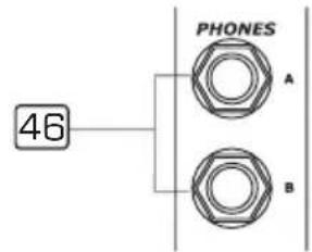
46 PHONES Jacks
These jacks will be used to send the signal to your headphones.

Rear Panel

47 POWER Switch
This switch is used to turn the main power on and off.
48 +48 Volt Phantom Power
It is available only to the XLR MIC sockets. Never plug in a microphone when phantom power is already on. Before turning phantom power on, make sure that all faders are totally down. In this way, you will protect your stage monitors and main loudspeakers.

4. CONTROL ELEMENTS
49 AC Inlet with FUSE Holder
Use it to connect your LYNX-MIX 124UM mixer to the main AC with the supplied AC cord. Please check the voltage available in your country and how the voltage for your LYNX-MIX 124UM mixer is configured before attempting to connect your LYNX-MIX 124UM mixer to the main AC.
50 MAIN MIX OUTPUT
These stereo outputs are supplied with both the XLR and 1/4" phone jacks and these outputs are controlled by the Main Mix Level.
51 MAIN OUTPUT LEVEL Button
This button sets the main mix output level to match the input of the device that you are going to connect. Engage this button to reduce the output level from MAIN MIX OUTPUT by 30 dBu, it is used to match a mic input@ -30, or a pro unit input @ +4 dBu.
52 USB PORT
This USB port is used to connect the unit to PC in a bi-directional way. The output signal can be chosen between the SUB1-2 or MAIN MIX output, While the input signal can be addressed to CH11/12 or MAIN MIX input.
53 USB RECORD Switch
You can select between SUB1/2 or MAIN MIX the signal to be recorded in your PC.
54 USB PLAYBACK Switch
You can select CH11/12 or MAIN MIX track to listen to PC audio signal.
55 MAIN INSERT
These two 1/4" phone jacks are stereo insert points and used to connect external processors such as compressors, equalisers etc.. When insert a external processor into the jack, the Main stereo signal will be sent out after the EQ and returned into the MAIN MIX output before the MAIN MIX fader.
56 MONO Level Control
This knob sets the level of mono mix output signal, which can be varied from -do +15 dB.
57 MONO OUTPUT Jack
This 1/4" phone jack is balanced/unbalanced mono mix output connector, it can be regarded as a sum output of the left and right of MAIN MIX.

4. CONTROL ELEMENTS
58 CTRL OUT Jacks
These 1/4" phone jacks will be used to send the Control Room signal to the studio monitor speakers or a second set of PA.
59 DFX OUT Jack
This 1/4" phone jack is used to output the effect signal generated from internal DSP module. DSP output signal level can be controlled by the EFFECTS OUT (41) control.
60 FOOTSWITCH Jack
This 1/4" phone jack can be used to connect an external footswitch to turn on/off the onboard effect module.
61 AUX SENDS Jacks
These 1/4" phone jacks are used to send out the signal from the AUX Bus to external devices such as effect units and/or stage monitors.
62 AUX RETURNS Jacks
Use these stereo 1/4" phone jacks to return the stereo signal of an effect unit to the Main Mix. Alternatively you can also use them as an extra auxiliary input via using the AUX RETURN level control as volume control. The signal will be sent directly to MAIN MIX control.
63 DIRECT OUTS
Each Mono MIC/LINE Channel (CH1-CH4) is equipped with a 1/4" phone jack for direct output signal. These jacks are used to send the signal from the channel path to external device for recording function etc..
64 SUBGROUPS OUT Jacks
These 1/4" phone jacks are used to to record or to connect another sound system, using different levels and signals from MAIN MIX OUT.
65 SUBGROUPS INSERT
These 1/4" TRS phone jacks are insert points. They are configured in a standard way (Tip Send/Ring Return) to be used to connect external processors, such as compressor, limiter, EQ etc.. Inserting a "Y" shaped cable in these jacks, the subgroup signal path will be sent to external unit, then returned before subgroups fader. Connect the external unit input to "Y" shaped cable Tip, and external unit output to "Y" shaped cable Ring.

5. INSTALLATION AND CONNECTION
Ok, you have got to this point and you are now in the position to successfully operate your LYNX-MIX 124UM. However, we advise you to read the following section carefully to be the real master of your own mix. Not paying enough attention to the input signal level, the routing of the signal and the assignment of the signal will result in unwanted distortion, a corrupted signal or no sound at all. So you should follow this procedure for every single channel:
- Turn down all Input and output gain controls.
- Connect phantom powered microphones before switching on the +48 Volt phantom power switch.
- Set the output level of your LYNX-MIX 124UM mixer as "O", and the connected power amplifier at no more than 75%.
- Now, set the CONTROL ROOM/PHONES level at no more than 50%. In this way, you will be able to hear later what you are doing connecting a pair of headphones or a pair of powered studio monitor speakers.
- Position EQ controls on middle position.
- Position panoramic (PAN/BAL) control on center position.
- With a pair of headphone or studio monitor speakers are connected, apply a Line Level input signal so that the PEAK LED does not light up.
- Increase the input gain properly for maintaining the good headroom and ideal dynamic range.
- Depending on the actual application, turn slowly the input and output level controls for obtaining the maximum gain before distortion.
- Now repeat the same sequence for all input channels. The main LED meter could move up into the red section. In this case you can adjust the overall output level through the main mix control.
Audio Connections
You can connect unbalanced equipment to balanced inputs and outputs. Simply follow these schematics.

1/4" Stereo (TRS) Jack Plug

1/4" Mono (TS) Jack Plug

1/4" Stereo (TRS) Jack Plug

Use for Balanced Mic Inputs (For unbalanced use, connect pin 1 to 3)
3-pin XLR Male Plug
(seen from soldering side)
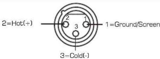
Use for Main output (For unbalanced use, leave pin3 unconnected)
3-pin XLR Line Socket
(seen from soldering side)

'Tapped' Connection Direct Output Lead
(Enables the Insert to be used as a Direct Output while maintaining the channel signal flow)

Y-Stereo lead for insert Connection
(To be used when the processor does not employ a single jack connection for the In/Out Connections)
USB Connection

natural_image
Diagram of three connected electrical connectors with fuse and socket symbols (no text or labels)
6. The Operation Instructions for Mp3
1. Note
a. USB Memory Format: FAT16, FAT32
b. Playing Type: Only support MP3 playing
c. It can read up to 7 rank folders of your USB player.
2. Operation Instruction
2.1 when no USB KEY is inserted, your LYNX 124UM display will show the following screen:

Fig 1
2.2 Inserted the USB Key
The MP3 Player starts to search the MP3 songs in your USB key, and the display shows "Searching". At the end of the search, the display will show the following screen. Using "<" or ">>" keys, you can select one of following three menu options ("Playing", "Program", and "Folder List"). Pressing "Playing" the unit will enter into the corresponding operation mode.
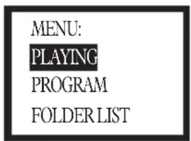
Fig 2
2.3 "Playing" mode - single song play
a. In Fig 2, selecting the "Playing" mode you will recall following screen. This screen displays the name of all the folders containing MP3 files. Using the "<>" or ">>" keys, you can scan the folders, then pressing "Play" key you will open the corresponding folder. Press "Stop" to return to Fig 2 screen.
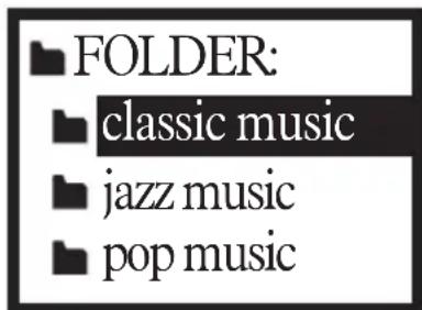
Fig 3

6. The Operation Instructions for Mp3
b. After opening the folder, the display will show a screen like the following one. This screen displays MP3 file list, and scrolling the list using "<<" or ">>" keys you can choose the desired song. Pressing the "Play" key, the selected song playback will start. In order to stop playback, you just need to press the "Stop" key. Then, if you press the "Play" key, the song playback will start from the pause point. If you press again the "Stop" key your LYNX-MIX124UM will return to Fig 3 screen.
![[ 0 0 2 ] 0 0 : 05 01. Plena pop 01.mp 02. pop 02.mp3 03. Plena pop 03.mp](/content/2026/05/912640/images/884a6eae730e454f7b5e36131bc5ac44ac2f7e2010024ebe883b93c821d12f5c.jpg)
Fig 4
2.4 "Program" mode
a. In Fig 2, select "Program" to enter into the following screen:
"Playlist Set": Set the playing list
"Playing List": Play list
Press "<<" or ">>" keys to select, press "Stop" key to return the Fig 2 screen.

Fig 5
b. After entering into the "Play List Set", the display will show Fig 3 screen. Selecting the desired folder, the display will show the following screen. This screen will show all the MP3 files, the selected song will be inserted into the playing list and a mark will appear. Pressing again you're going to delete the song from the playing list, and the mark will disappear. Pressing the "Stop" key, you will return to Fig 2 screen. The playing list can accept up to 20 songs, and it will display the list according to song insert order.

6. The Operation Instructions for Mp3
![classic music [ . ] p3 Plena pop [✓] Plena pop 02.mp [ . ] Plena pop 03.mp](/content/2026/05/912640/images/4ebafed7df38747df270e9e833408e36585c01dcb33499928b10cf5cbdf737ce.jpg)
Fig 6
c. The screen will display the following screen. Pressing the "<<" or ">>" keys you can select the starting song, then pressing the "Play" key the selected song playback will start. Pressing "Play" again, or pressing "Stop", the playback will stop. Pressing "Play" again, or pressing "Stop", the playback will start again from the same point. Twice pressing "Stop" the MP3 player will return to Fig 3 screen.
![[.] 0 0 : 2 0 ▶ 01. lena pop 02.mp3 02. Plena pop 06.mp 03. Plena pop 04.mp](/content/2026/05/912640/images/0b9628ec22e06d6f4931d782f9ec19506b4ab6df59fcbbf43484d7296b977103.jpg)
Fig 7
2.5 Folder List:
See the Fig 3, this screen displays MP3 files folders names. Use "<<" or ">>" keys to scan, pressing the "Playing" key, you'll enter into the corresponding folder. In order to return to Fig 5 screen, you just have to press the "Stop" key.
7. PRESET LIST
| NO. Preset Description | Controllable Parameter Parameter Variable range | |||
| 1 | VOCAL1 | Simulate a room with small delay time | Decay time Pre-delay | 0.8~1.1s 0~79ms |
| 2 | VOCAL2 | Simulate a small space with slight decay time | Decay time Pre-delay | 0.8~2.5s 0~79ms |
| 3 | LARGE HALL | Simulate a large acoustic space of the sound | Decay time Pre-delay | 3.6~5.4s 23~55ms |
| 4 | SMALL HALL | Simulate a small acoustic space of the sound | Decay time Pre-delay | 1.0~2.9s 20~45ms |
| 5 | LARGE ROOM | Simulate a studio room with many early reflections | Decay time Pre-delay | 2.9~4.5s 23~55ms |
| 6 | SMALL ROOM | Simulate a bright studio room | Decay time Pre-delay | 0.7~2.1s 20~45ms |
| 7 | PLATE | Simulate the transducers sound like classic bright vocal plate | Decay time Pre-delay | 0.6~6.1s 10ms |
| 8 | TAPE REVERB | Simulate a record head and multiple playback heads at intervals along the tape | Decay time Pre-delay | 1.3~5.4s 0~84ms |
| 9 | SPRING REVERB | Simulate the analog transducers' springs lightly stretched sound | Decay time Pre-delay | 1.3~5.4s 0~35ms |
| 10 | MONO DELAY | Reproduce the sound input on the output after a lapse of time | Period | 60~650ms |
| 11 | STEREO DELAY | Recreate the input sound on the stereo output with different time. | Period Feedback | 210~400ms 37~73% |
| 12 | FLANGER | Simulate to play with another person carrying out same the notes on the same instrument | Rate | 0.16~2.79Hz |
| 13 | CHORUS | Recreate the illusion of more than one instrument from a single instrument sound | Rate | 0.5~5Hz |
| 14 | REV.+DELAY | Delay with room effect | Decay period Rev.decay time | 211~375ms 1.0~2.9s |
| 15 | REV.+FLANGER | Stereo flanger and large room reverb | Flanger Rate Rev.decay time | 0.16~2.52Hz 1.5~2.9s |
| 16 | REV.+CHORUS | Stereo chorus and large room reverb | Chorus rate Rev.decay time | 0.5~4.74Hz 1.5~2.9s |
8. BLOCK DIAGRAM

flowchart
graph TD
    A["输入信号"] --> B["MP-ROAD"]
    B --> C["LED"]
    C --> D["Capacitor 1"]
    D --> E["Capacitor 2"]
    E --> F["Capacitor 3"]
    F --> G["Capacitor 4"]
    G --> H["Capacitor 5"]
    H --> I["Capacitor 6"]
    I --> J["Capacitor 7"]
    J --> K["Capacitor 8"]
    K --> L["Capacitor 9"]
    L --> M["Capacitor 10"]
    M --> N["Capacitor 11"]
    N --> O["Capacitor 12"]
    O --> P["Capacitor 13"]
    P --> Q["Capacitor 14"]
    Q --> R["Capacitor 15"]
    R --> S["Capacitor 16"]
    S --> T["Capacitor 17"]
    T --> U["Capacitor 18"]
    U --> V["Capacitor 19"]
    V --> W["Capacitor 20"]
    W --> X["Capacitor 21"]
    X --> Y["Capacitor 22"]
    Y --> Z["Capacitor 23"]
    Z --> AA["Capacitor 24"]
    AA --> AB["Capacitor 25"]
    AB --> AC["Capacitor 26"]
    AC --> AD["Capacitor 27"]
    AD --> AE["Capacitor 28"]
    AE --> AF["Capacitor 29"]
    AF --> AG["Capacitor 30"]
    AG --> AH["Capacitor 31"]
    AH --> AI["Capacitor 32"]
    AI --> AJ["Capacitor 33"]
    AJ --> AK["Capacitor 34"]
    AK --> AL["Capacitor 35"]
    AL --> AM["Capacitor 36"]
    AM --> AN["Capacitor 37"]
    AN --> AO["Capacitor 38"]
    AO --> AP["Capacitor 39"]
    AP --> AQ["Capacitor 40"]
    AQ --> AR["Capacitor 41"]
    AR --> AS["Capacitor 42"]
    AS --> AT["Capacitor 43"]
    AT --> AU["Capacitor 44"]
    AU --> AV["Capacitor 45"]
    AV --> AW["Capacitor 46"]
    AW --> AX["Capacitor 47"]
    AX --> AY["Capacitor 48"]
    AY --> AZ["Capacitor 49"]
    AZ --> BA["Capacitor 50"]
    BA --> BB["Capacitor 51"]
    BB --> BC["Capacitor 52"]
    BC --> BD["Capacitor 53"]
    BD --> BE["Capacitor 54"]
    BE --> BF["Capacitor 55"]
    BF --> BG["Capacitor 56"]
    BG --> BH["Capacitor 57"]
    BH --> BI["Capacitor 58"]
    BI --> BJ["Capacitor 59"]
    BJ --> BK["Capacitor 60"]
    BK --> BL["Capacitor 61"]
    BL --> BM["Capacitor 62"]
    BM --> BN["Capacitor 63"]
    BN --> BO["Capacitor 64"]
    BO --> BP["Capacitor 65"]
    BP --> BQ["Capacitor 66"]
    BQ --> BR["Capacitor 67"]
    BR --> BS["Capacitor 68"]
    BS --> BT["Capacitor 69"]
    BT --> BU["Capacitor 70"]
    BU --> BV["Capacitor 71"]
    BV --> BW["Capacitor 72"]
    BW --> BX["Capacitor 73"]
    BX --> BY["Capacitor 74"]
    BY --> BZ["Capacitor 75"]
    BZ --> CA["Capacitor 76"]
    CA --> CB["Capacitor 77"]
    CB --> CC["Capacitor 78"]
    CC --> CD["Capacitor 79"]
    CD --> CE["Capacitor 80"]
    CE --> CF["Capacitor 81"]
    CF --> CG["Capacitor 82"]
    CG --> CH["Capacitor 83"]
    CH --> CI["Capacitor 84"]
    CI --> CJ["Capacitor 85"]
    CJ --> CK["Capacitor 86"]
    CK --> CL["Capacitor 87"]
    CL --> CM["Capacitor 88"]
    CM --> CN["Capacitor 89"]
    CN --> CO["Capacitor 90"]
    CO --> CP["Capacitor 91"]
    CP --> CQ["CPACITOR 92"]
    CQ --> CY["CPACITOR 93"]
    CY --> CZ["CPACITOR 94"]
    CZ --> DA["CPACITOR 95"]
    DA --> DB["CPACITOR 96"]
    DB --> DC["CPACITOR 97"]
    DC --> DD["CPACITOR 98"]
    DD --> DE["CPACITOR 99"]
9. TECHNICAL SPECIFICATION
Mono Input Channels
| Microphone Input | Electronically balanced, discrete input configuration |
| Frequency Response | 10 Hz to 55 kHz, +/-3 dB |
| Distortion (THD & N) | 0.005% at +4 dBu, 1 kHz |
| Gain Range | 0 dB to 50 dB (MIC) |
| SNR (Signal to Noise Ratio) | 115 dB |
| Line Input | Electronically balanced |
| Frequency Response | 10 Hz to 55 kHz, +/-3 dB |
| Distortion (THD & N) | 0.005% at +4 dBu, 1 kHz |
| Sensitivity Range | +15 dBu to -35 dBu |
Stereo Input Channels
| Line Input | Balanced/Unbalanced |
| Frequency Response | 10 Hz to 55 kHz, +/-3 dB |
| Distortion (THD & N) | 0.005% at +4 dBu, 1 kHz |
| Inpedances | |
| Microphone Input | 1.4 kOhm |
| Channel Insert Return | 2.5 kOhm |
| All Other Inputs | 10 kOhm or greater |
| Tape Out | 1 kOhm |
| All Other Output | 120 Ohm |
Equalization
| Hi-shelving | +/-15 dB @12 kHz |
| Mid bell (Mono) | +/-15 dB -frequency range 100 Hz~8 kHz |
| Hi-Mid (Stereo) | +/-15 dB @ 3 k Hz |
| Mid-Low (Stereo) | +/-15 dB @ 500 Hz |
| Low-shelving | +/-15 dB @ 80 Hz |
| Low Cut Filter | 75 Hz, 18 dB/Oct. |
DSP Section
| A/D & D/A Converters 24-Bit | |
| DSP Resolution | 24-Bit |
| Type of Effects | Hall, Room, Vocal & Plate REVERBSMono & Stereo DELAY (Max DELAY TIME 650ms)Chorus, Flanger & Reverb MODULATIONS, REVERB+DELAYREVERB+CHORUS, REVERB+FLANGER Combinations |
| Presets | 256 |
| Controls | 16-Position PRESET/VARIATION SelectorDSP MUTE SWITCH with PEAK LED Indicator |
Main Mix Section
| Noise (Bus Noise) | Fader 0 dB, Channels Muted: -100 dBr (ref.: +4 dBu) |
| Fader 0 dB, all input channels assigned and set toUNITY Gain: -90 dBr (ref.: +4 dBu) | |
| Max Output | +22 dBu Balanced XLR; +22 dBu Unbalanced, 1/4" jacks |
| AUX Returns Gain Range | - do +15 dB |
| +22 dBuAUX Sends Max Out |
Power Supply
| Main Voltage | USA/Canada | 100-120 VAC~60 Hz |
| Europe 210-240 VAC~ | 50 Hz | |
| U.K./Australia | 240 VAC~ 50 Hz | |
| Power Consumption | 40 Watts | |
| Fuse | T1.25 AL | |
| Standard IEC ReceptacleMain Connection | ||
Physical
| Dimension (W×D×H) | 415 mm×400 mm×38/115 mm (16.34"x15.75"x1.49"/4.53") |
| Net Weight | 6.7 Kg (14.8 lb) |
10. WARRANTY
1. WARRANTY REGISTRATION CARD
To obtain Warranty Service, the buyer should first fill out and return the enclosed Warranty Registration Card within 10 days of the Purchase Date.
All the information presented in this Warranty Registration Card gives the manufacturer a better understanding of the sales status, so as to provide a more effective and efficient after-sales warranty service. Please fill out all the information carefully and genuinely, miswriting or absence of this card will void your warranty service.
2. RETURN NOTICE
2.1 In case of return for any warranty service, please make sure that the product is well packed in its original shipping carton, and it can protect your unit from any other extra damage.
2.2 Please provide a copy of your sales receipt or other proof of purchase with the returned machine, and give detail information about your return address and contact telephone number.
2.3 A brief description of the defect will be appreciated.
2.4 Please prepay all the costs involved in the return shipping, handling and insurance.
3. TERMS AND CONDITIONS
3.1 WTO warrants that this product will be free from any defects in materials and/or workmanship for a period of 1 year from the purchase date if you have completed the Warranty Registration Card in time.
3.2 The warranty service is only available to the original consumer, who purchased this product directly from the retail dealer, and it can not be transferred.
3.3 During the warranty service, LTO may repair or replace this product at its own option at no charge to you for parts or for labor in accordance with the right side of this limited warranty.
3.4 This warranty does not apply to the damages to this product that occurred as the following conditions:
- Instead of operating in accordance with the user's manual thoroughly, any abuse or misuse of this product.
• Normal tear and wear.
• The product has been altered or modified in any way. - Damage which may have been caused either directly or indirectly by another product / force / etc.
- Abnormal service or repairing by anyone other than the qualified personnel or technician.
And in such cases, all the expenses will be charged to the buyer.
3.5 In no event shall ▲□ be liable for any incidental or consequential damages. Some states do not allow the exclusion or limitation of incidental or consequential damages, so the above exclusion or limitation may not apply to you.
3.6 This warranty gives you the specific rights, and these rights are compatible with the state laws, you may also have other statutory rights that may vary from state to state.
SEIKAKU TECHNICAL GROUP LIMITED
NO. 1, Lane 17, Sec. 2, Han Shi West Road, Taichung 40151, Taiwan www.altoproaudio.com Tel: 886-4-22313737
email: info@altoproaudio.com Fax: 886-4-22346757
All rights reserved to ALTO. All features and content might be changed without prior notice. Any photocopy, translation, or reproduction of part of this manual without written permission is forbidden. Copyright 2008 Seikaku Group

- IMPORTANT SAFETY INSTRUCTION
- CAUTION
- WARNING
- IN THIS MANUAL
- INTRODUCTION
- FEATURES
- LARGE GIG HOOKUP DIAGRAM
- CONTROL ELEMENTS
- MONO MIC/LINE Channels
- STEREO INPUTS
- MONO Channel INSERT
- TRIM
- LINE GAIN
- LEVEL SET LED
- LOW-CUT Button
- LINE/MP3 Button
- LINE/USB Button
- EQUALISER
- HI
- MID
- HI-MID
- MID-LOW
- LOW
- AUX SENDS Level Control
- PAN/BAL Control
- PEAK LED
- MUTE Button & LED
- ASSIGNMENT Controls
- FADER
- Control Room Source
- PHONES/CTRL ROOM Controls
- Master AUX SENDS Controls
- SOLO Button
- Master STEREO AUX RETURNS Controls
- TO AUX SEND1/2
- MAIN MIX & CTRL/R Button
- SUB1-2/SUB3-4/MAIN MIX Buttons
- AUX RETURNS SOLO Button
- SUBGROUPS ASSIGN TO MAIN MIX
- SUBGROUPS Fader
- LED Meter
- 2TK TO MIX Button
- SOLO MODE Button
- EQ Switch
- STEREO GRAPHIC EQ
- DSP SECTION
- PRESETS
- VARIATIONS
- DSP MUTE Switch & PEAK LED
- EFFECTS OUT Control
- DFX2 (INT) RETURN EFFECTS TO MONITOR
- POWER LED
- PHANTOM LED
- Mp3 Player
- Note:
- 2-TRACK IN/OUT
- PHONES Jacks
- Rear Panel
- POWER Switch
- +48 Volt Phantom Power
- AC Inlet with FUSE Holder
- MAIN MIX OUTPUT
- MAIN OUTPUT LEVEL Button
- USB PORT
- USB RECORD Switch
- USB PLAYBACK Switch
- MAIN INSERT
- MONO Level Control
- MONO OUTPUT Jack
- CTRL OUT Jacks
- DFX OUT Jack
- FOOTSWITCH Jack
- AUX SENDS Jacks
- AUX RETURNS Jacks
- DIRECT OUTS
- SUBGROUPS OUT Jacks
- SUBGROUPS INSERT
- INSTALLATION AND CONNECTION
- Audio Connections
- 3-pin XLR Male Plug
- 3-pin XLR Line Socket
- The Operation Instructions for Mp3
- Note
- Operation Instruction
- Inserted the USB Key
- "Playing" mode - single song play
- "Program" mode
- Folder List:
- PRESET LIST
- BLOCK DIAGRAM
- TECHNICAL SPECIFICATION
- WARRANTY
- WARRANTY REGISTRATION CARD
- RETURN NOTICE
- TERMS AND CONDITIONS
- SEIKAKU TECHNICAL GROUP LIMITED
Brand : ALTO
Model : LYNX-MIX124UM
Category : Hand blender