
AWA6220-W - Wi-Fi Router Dahua Technology - Free user manual and instructions
Find the device manual for free AWA6220-W Dahua Technology in PDF.


| Product Type | Wireless Access Point (Indoor) |
| Model | AWA6220-W |
| Brand | Dahua Technology |
| Dimensions (H × W × D) | 30 × 160 × 86 mm (1.18 × 6.30 × 3.39 in) |
| Weight | 0.25 kg (0.55 lb) |
| Antenna Type | Internal antennas |
| Wireless Standards | IEEE 802.11a/b/g/n/ac/ax |
| Power over Ethernet (PoE) | Supported (802.3af/at) |
| PoE Standard | 802.3af/at |
| Power Consumption (without USB) | ≤ 12.95 W |
| Power Consumption (with USB) | ≤ 15.45 W |
| Local Power Adapter Input | 100 VAC to 240 VAC |
| Local Power Adapter Output | 48 VDC to 54 VDC, ≥ 16 W |
| Operating Temperature | 0°C to 40°C (32°F to 104°F) |
| Storage Temperature | -40°C to +70°C (-40°F to +158°F) |
| Operating Humidity | 5% RH to 95% RH, noncondensing |
| Network Ports | 4 × 10/100/1000M Ethernet (GE1/0/2 to GE1/0/5) |
| Uplink/PoE In Port | 1 × 10/100/1000M Ethernet (GE1/0/1), PoE input |
| Console Port | 1 × RJ-45 console (for technical personnel) |
| USB Port | 1 × USB (charging and data read/write) |
| Pass-through Ports | 2 × RJ-45 (for phone or Ethernet cables) |
| Power Port | 1 × DC jack (54 V) |
| LED Indicators | Power, Radio, Uplink, 4 Ethernet ports, Reset button |
| Reset Button | Press 0-5 seconds: reset; Press 5-20 seconds: factory defaults |
| Mounting | Wall mount (mounting bracket included) |
| Included Accessories | Mounting bracket, M4×25 screws, M3×4 security screw |
Frequently Asked Questions - AWA6220-W Dahua Technology
User questions about AWA6220-W Dahua Technology
0 question about this device. Answer the ones you know or ask your own.
Ask a new question about this device
Download the instructions for your Wi-Fi Router in PDF format for free! Find your manual AWA6220-W - Dahua Technology and take your electronic device back in hand. On this page are published all the documents necessary for the use of your device. AWA6220-W by Dahua Technology.
USER MANUAL AWA6220-W Dahua Technology
1 Preparing for installation.... 1-1
Safety recommendations 1-1
Site preparation 1-1
Installation accessories 1-1
Installation tools 1-2
Device and mounting bracket dimensions 1-2
2 Installing the AP 2-1
Installation flowchart 2-1
Pre-installation tasks 2-1
Mounting the AP 2-1
Powering the AP 2-3
Connecting a PoE power source 2-3
Connecting a local power source 2-3
Check after power-on 2-4
Connecting the AP to the network 2-4
3 Appendix A Hardware information and specifications 3-1
Ports 3-1
Technical specifications 3-2
LEDs 3-3
1 Preparing for installation
Safety recommendations

WARNING!
Only professional technical personnel can install and remove the AP and its accessories. You must read all safety instructions carefully before working with the AP.
To avoid possible bodily injury and equipment damage, read the following safety recommendations before installing the AP. Note that the recommendations do not cover every possible hazardous condition.
• To avoid bodily injury and device damage, take adequate safety measures.
- Place the AP in a dry and flat location and take anti-slip measures.
- Keep the AP clean and dust-free.
- Do not place the AP in a moist area and avoid liquid intrusion.
- Keep the AP and installation tools away from walkways.
Site preparation
Before installing the AP, examine the installation site and ensure that the AP will operate in a favorable environment. Make sure the temperature and humidity at the installation site meet the requirements in Table 1-1.
Table 1-1 Temperature and humidity requirements
| Item | Specification |
| Operating temperature | 0°C to 40°C (32°F to 104°F) |
| Storage temperature | -40°C to +70°C (-40°F to +158°F) |
| Operating humidity | 5% RH to 95% RH, noncondensing |
Installation accessories
Figure 1-1 Accessories provided with the AP

M3 ×4 security screw

M4×25 screw
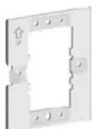
Mounting bracket
Installation tools
When installing the AP, you might need the following tools. Prepare the installation tools yourself as required.
Figure 1-2 Installation tools
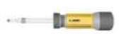
Philips screwdriver

Needle-nose screwdriver

Wire stripper

Wire crimper
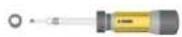
Torx screwdriver
Device and mounting bracket dimensions
Figure 1-3 AP dimensions

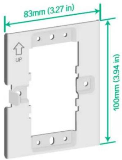
Figure 1-4 Mounting bracket dimensions
2 Installing the AP
Installation flowchart
Figure 2-1 Installation flowchart

flowchart
graph TD
    A["Start"] --> B["Complete pre-installation tasks"]
    B --> C["Install the AP"]
    C --> D["Power the AP"]
    D --> E["Connect the AP to the network"]
    E --> F["End"]
Pre-installation tasks
Before installing the AP, perform the following tasks:
- Power on the AP and connect the AP to the network. Examine the LEDs to verify that the AP is operating correctly. For information about the LEDs, see "LEDs."
• Record the MAC address and serial number of the AP for future use.
Mounting the AP
- As shown in Figure 2-2, use M4 screws to attach the mounting bracket to an electrical outlet box.
Figure 2-2 Attaching the mounting bracket to an electrical outlet box

- As shown in Figure 2-3, connect cables to the pass-through port and uplink/PoE in port on the rear of the AP.
The pass-through ports on the rear and bottom of the AP are standard RJ-45 ports. You can connect phone cables or Ethernet cables to the pass-through ports as needed.
Figure 2-3 Connecting a cable to the uplink/PoE in port

natural_image
Diagram showing connection between a wall-mounted device and a server rack with a green arrow indicating upward motion (no text or symbols present)- Secure the AP to the mounting bracket, as shown in Figure 2-4.
a. Align the mounting peg on the mounting bracket with the installation slot in the rear of the AP and insert the peg into the slot.
b. Slide down the AP so that it sits securely on the peg.
c. Fasten the M3 × 4 screw on the side panel of the AP.
Figure 2-4 Securing the AP to the mounting bracket

Powering the AP
You can supply power to the AP by using a local power source or through 802.3af/802.at PoE as required. Before powering the AP, make sure the local power source or the power sourcing equipment (PSE) is reliably grounded.
Connecting a PoE power source
To power the AP through PoE, use an Ethernet cable to connect an Ethernet port on a PoE switch to the uplink/PoE in port on the AP.
Figure 2-5 Powering the AP through PoE

natural_image
Illustration of a network switch device with two ports and a separate server tower (no text or symbols visible)Connecting a local power source
You can use an AC/DC power adapter to connect the AP to a local power source. No power adapter is provided with the AP. Prepare one yourself as required. Table 2-1 describes the power adapter specifications.
Table 2-1 Power adapter specifications
| Item | Specification |
| Input | 100 VAC to 240 VAC |
| Output | 48 VDC to 54 VDC |
| Output power | ≥ 16 W |
Figure 2-6 Using a power adapter to connect the AP to a local power source

natural_image
Illustration of a network device with cable and plug connections (no text or symbols)Check after power-on
Examine the LEDs on the AP after you power on it to verify that the AP is operating correctly. For more information about the LEDs, see "LEDs."
Connecting the AP to the network
All AP settings are configured on the AC. To verify network connectivity of the AP, execute the display wlan ap all command on the AC. If the AP status is R/M, the AP has been connected to the network.
<AC> display wlan ap all
Total number of APs: 1
Total number of connected APs: 1
Total number of connected manual APs: 1
Total number of connected auto APs: 0
Total number of connected common APs: 1
Total number of connected WTUs: 0
Total number of inside APs: 0
Maximum supported APs: 3072
Remaining APs: 3071
Total AP licenses: 128
Remaining AP licenses: 127
AP information
State : I = Idle,    J = Join,    JA = JoinAck,    IL = ImageLoad
C = Config,    DC = DataCheck,    R = Run    M = Master,    B = Backup
AP name
AP ID
State
Model
Serial ID
ap1
1
R/M
DH-AWA6220-W
219801A3CA8199E00001
3 Appendix A Hardware information and specifications
Ports
Figure 3-1 Ports on the AP

(1) 10/100/1000M Ethernet copper ports
(2) Pass-through port

(1) Power port
(2) Security screw hole

(1) Reset button (RST)
(2) Console port
(3) USB port
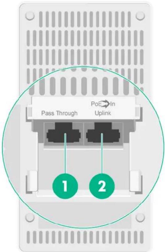
(1) Pass-through port
(2) Uplink/PoE in port
Technical specifications
Table 3-1 Technical specifications
| Item | Specification |
| Dimensions (H × W × D) | 30 × 160 × 86 mm (1.18 × 6.30 × 3.39 in) |
| Weight | 0.25 kg (0.55 lb) |
| Antenna | Internal antennas |
| Power consumption | • ≤ 12.95 W without a USB device attached• ≤ 15.45 W with a USB device attached |
| Standards | • IEEE802.11a/b/g/n/ac/ax• IEEE802.3af/at |
| Console port | Used by technical personnel only for device configuration and management. |
| 10/100/1000M Ethernet copper port (1 to 4) | Represented by interface number GE1/0/2 to GE1/0/5 in the MAP file and GigabitEthernet 2 to GigabitEthernet 5 on the AC. |
| Uplink/PoE in port (10/100/1000M Ethernet copper port) | Used for connecting the AP to an uplink device for Internet or MAN access. It can also receive PoE power from the uplink device.It is represented by interface number GE1/0/1 in the MAP file andGigabitEthernet 1 on the AC. |
| Power port (54 V) | Used for receiving +54 VDC power from a local power source. |
| Pass-through port (2 in total) | Use for connecting a phone cable or RJ-45 cable. |
| USB port | Used for charging as well as data reading or writing. |
| Reset button | Functions of the reset button vary by the pressing duration. For more information, see Table 3-3. |
LEDs
Figure 3-2 LEDs on the AP
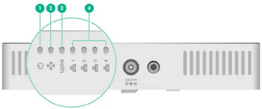
| (1) Power status LED | (2) Radio status LED |
| (3) Uplink port status LED | (4) Ethernet port status LEDs |
Table 3-2 LED descriptions
| LED | Status | Description |
| Power status LED | Off | No power is present or the LED has been disabled. |
| Steady yellow | The device is initializing or an initialization exception has occurred. | |
| Flashing yellow at 1 Hz | No radio cards have been detected. | |
| Flashing yellow at 2 Hz | The Ethernet interfaces are down and no mesh links are established. | |
| Steady green | The AP has started up and registered to an AC, and is in standby state. | |
| Flashing green at 0.5 Hz | The AP has started up but has not registered to any AC. | |
| Flashing green at 2 Hz | The AP is upgrading the image. | |
| Radio status LED | Off | The radios do not have associated clients, or the LED has been turned off from the CLI. |
| Flashing green at 1 Hz | Only the 2.4G radio has associated clients. | |
| Flashing yellow at 1 Hz | Only the 5G radio has associated clients. | |
| Alternating between green and blue at 1 Hz | Both the 2.4G and 5G radios have associated clients. | |
| Uplink port status LED | Off | No power is present. |
| Steady yellow | The port has been auto-negotiated to operate at 10/100 Mbps. | |
| Flashing yellow | The port is sending or receiving data at 10/100 Mbps. | |
| Steady green | The port has been auto-negotiated to operate at 1000 Mbps. | |
| Flashing green | The port is sending or receiving data at 1000 Mbps. | |
| Ethernet port status LED | Off | No link is present on the port. |
| Steady yellow | The port has been auto-negotiated to operate at 10/100 Mbps. | |
| Flashing yellow | The port is sending or receiving data at 10/100 Mbps. | |
| Steady green | The port has been auto-negotiated to operate at 1000 Mbps. | |
| Flashing green | The port is sending or receiving data at 2000 Mbps. |
Table 3-3 Reset button LED descriptions
| LED | Pressing duration (seconds) | Status | Description | |
| Reset button (RESET) | 0 to 5 | Green | Steady on | Used to reset the AP. |
| 5 to 20 | Green | Flashing at 2 Hz | Used to restore the factory default. | |

- Preparing for installation.... 1-1
- Installing the AP 2-1
- Appendix A Hardware information and specifications 3-1
- Preparing for installation
- Safety recommendations
- WARNING!
- Site preparation
- Installation accessories
- Installation tools
- Device and mounting bracket dimensions
- Installing the AP
- Installation flowchart
- Pre-installation tasks
- Mounting the AP
- Powering the AP
- Connecting a PoE power source
- Connecting a local power source
- Check after power-on
- Connecting the AP to the network
- Appendix A Hardware information and specifications
- Ports
- Technical specifications
- LEDs
Brand : Dahua Technology
Model : AWA6220-W
Category : Wi-Fi Router